Louie da fly
-
Posts
7,993 -
Joined
-
Last visited
Content Type
Profiles
Forums
Gallery
Events
Everything posted by Louie da fly
-
 Perhaps you need one of those 'funny' tanks they used on the Normandy beaches. Only 3778 miles across the Atlantic - a doddle! Steven
 -
Those are beautiful locomotives. Steven
-
Horses for courses, mate. Do what works for you. I've been woodcarving since I was a kid, and I get a lot of enjoyment out of it. Doesn't mean everyone else has to be the same or do what I do. Those figures of yours look really good. Australia got rid of its one and two-cent coins in 1992. We don't miss them. Those are brilliant, mate! Looking forward to seeing how they turn out in the real world! Steven
-
I find that leaving the thread to hang with weights on the end (as you do) but without glue eventually takes the kinks/curl out, but it does take awhile. Once that's done, impregnating the thread with a solution of PVA glue and water allows it to hang in a catenary curve if you support both ends, and it dries with the curve intact. Coming along nicely. Steven
- 176 replies
-
- 2
-

-

-
- la reale de france
- heller
- (and 2 more)
-
In retrospect, I'd agree. But I was young and no challenge seemed to be too much. I may have learned a bit of wisdom since, but I try to keep the attitude I had back then. What nationality is the locomotive in the picture? Steven
-
Thanks, Mark. I'll need to look at this a few times to get my head around it (that's the way my mind works, I'm afraid.) Yes, it might not be appropriate to this build, but ten again it might. Steven
-
Yep. I really wasn't sure it would turn out that way. I used river redgum (I think! I bought it from the guy across the road who used to own a farm and got the timber off trees growing there - some Aussie eucalypt,anyway) and the combination of that and Danish oil turned out exactly right, fortunately. Steven
- 110 replies
-
- 7
-
-
- Paddlewheeler
- Ballarat
- (and 3 more)
-
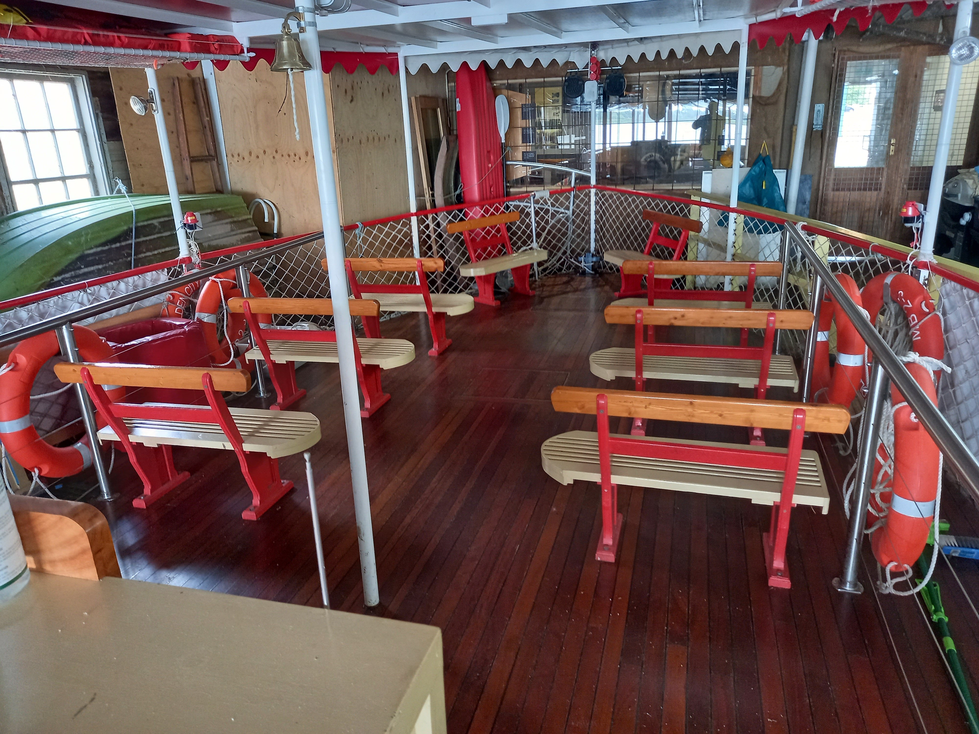
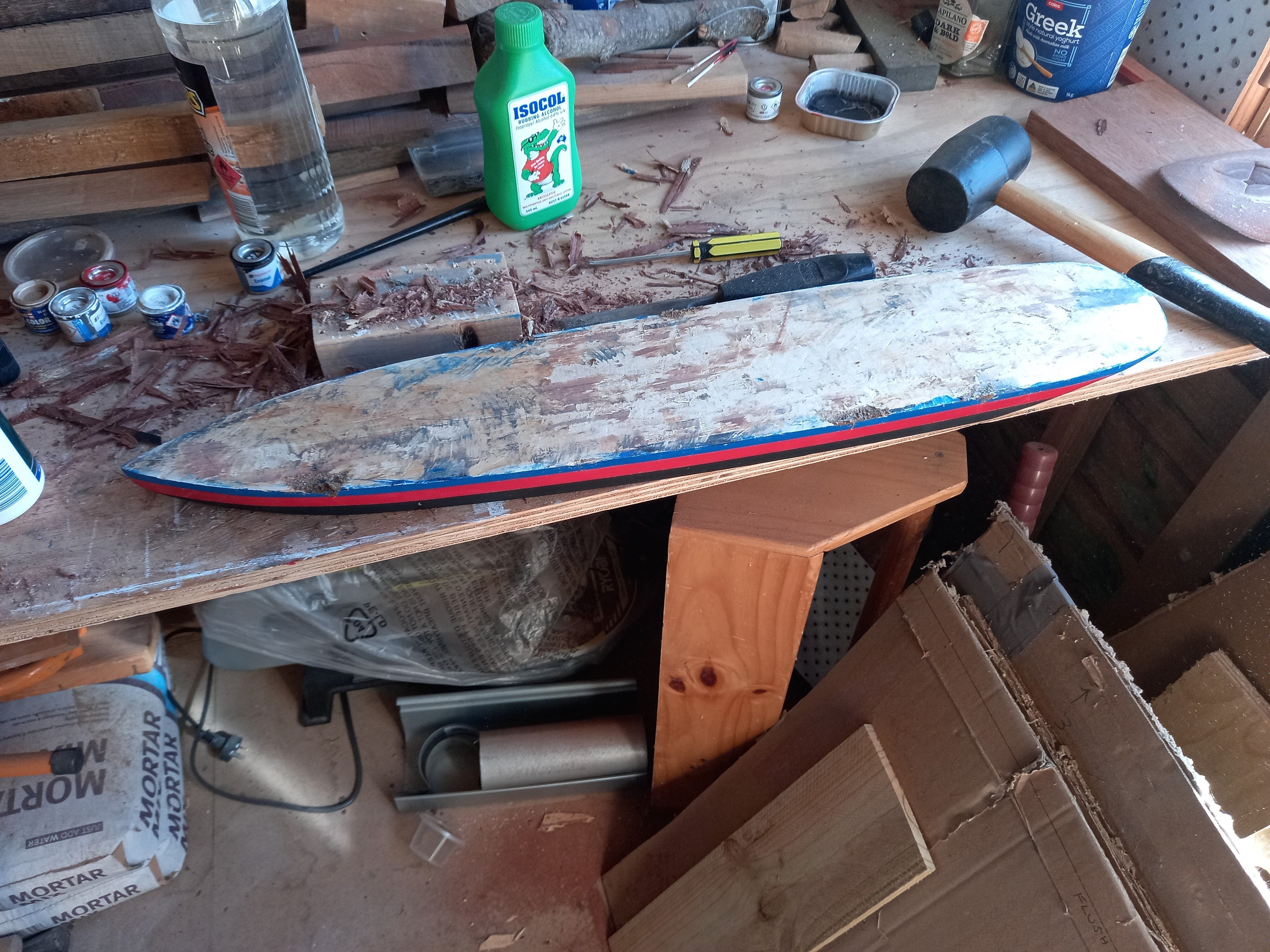
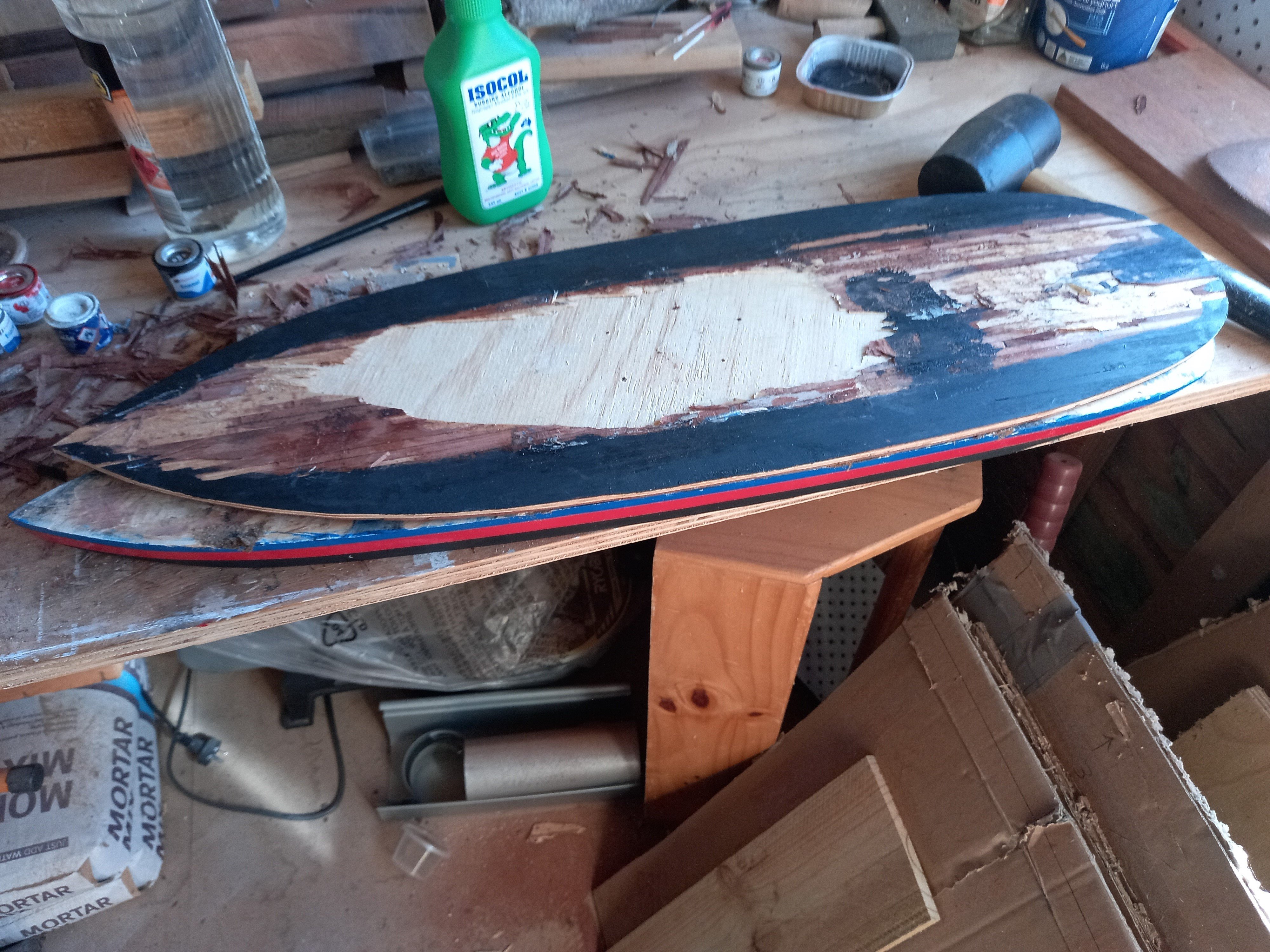
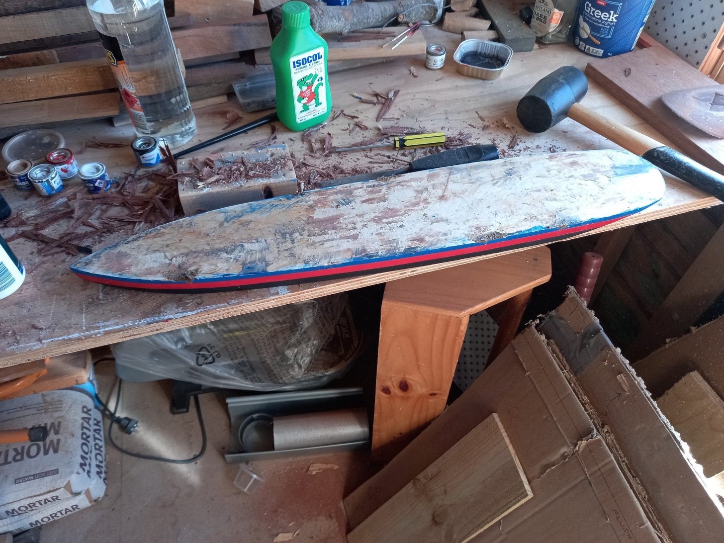
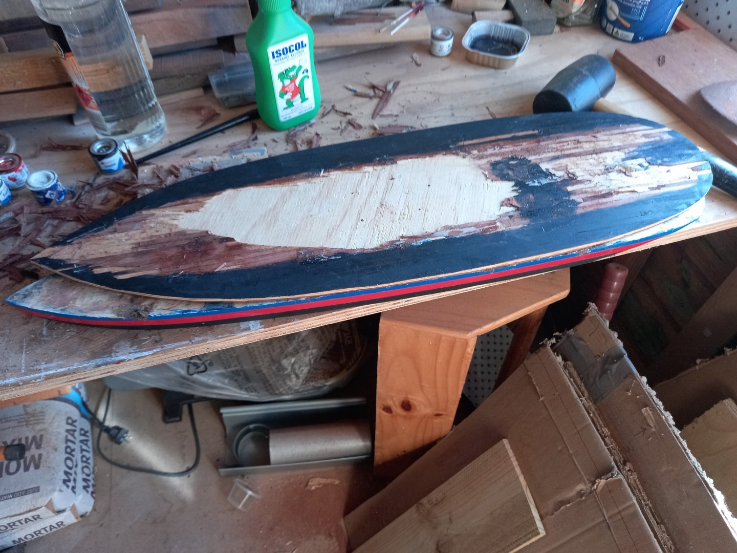
Yes, I thought I'd completely ruined the whole build over a moment's inattention. I'd taken so much care to make sure the two pieces were rigidly glued together, and then to find that I'd got the alignment wrong (checking it would have taken all of a minute!) and I couldn't get them apart again was heartbreaking. I had all kinds of ideas about making a complete new upper section, and ways to duplicate the look of the planking without having to do it plank by plank all over again. Took me some weeks to realise that with a bit of ingenuity and the fortunate quality of wood that it can be almost infinitely repaired that I could re-use both pieces after all. And here she is after staining the deck. And a colour comparison with the real thing. Steven

- 110 replies
-
- 20
-
-

-
- Paddlewheeler
- Ballarat
- (and 3 more)
-
Yes, that's what I thought. But a rope loop and a toggle do the same job and are a very Mediterranean solution. No idea about turning off auto-correct. Go to the How to use the MSW forum - **NO MODELING CONTENT** section on the home page and ask. A moderator will almost certainly be able to help. That's what that section's for. Steven
-
In fact I'll be having a block and tackle on each side, but using toggles to join them to the sail, not hooks. Nope. I've already made my decision on that. It's not worth the extra work for something I don't find particularly bothersome. BTW, regarding the vangs, though there are certainly a good number that are part-way down the yard, there are also quite a few well-observed contemporary representations showing them right on the extreme end. So I'm happy to leave them where they are for this model, and will simply do it differently next time. Steven
-
Immediately reminded me of the Monty Python sketch . . . Steven
-
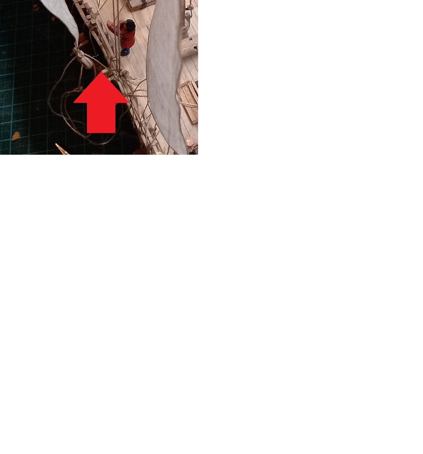
Thanks for that, Ferrus. This ties in with what I was thinking. I'd already all but decided to reduce the blocks at the clew to a single one per sail. What's the thought with the hook on the block? Is the idea to hook it into one of those rope coils on each side of your caravel's deck, depending on what tack you're on? I'll have to give that one some thought. Good point about the vangs - I'd thought "vangs at the extreme ends of the yards = greater turning force." But (and I have noticed these things further down the yard in both contemporary pictures and in photos) that presupposes unlimited sideways space at deck level to pull the yard to the side. Which of course there isn't. So further down is better after all. And the pendant (the standing line) between the yard and the block is borne out by both photos and near-contemporary (only 140 years later) images. Thanks for the comment regarding the loosened shrouds on the lee side. I got that (of course!) from Björn Landström's superb explanation in his book The Ship. Steven PS: By the way, one thing this build has taught me is that I need to put more forethought into belaying points before I start building, not just say "ah, that should be enough"and hope it turns out ok. So many belaying points, even on a (fairly) simple lateener.
-
OK - another question. I've just been looking at video of the caravel reconstruction Notorious and she only has a single block at the clew of each sail. Check out the footage. There's another video up of a caravel reconstruction under sail, but it doesn't show very much. So am I doing too much by having a pair of blocks at each clew? Should I remove one of them and simplify the rig? Particularly as my model is an early vessel with what we should probably assume was an unsophisticated rig? Unfortunately, contemporary representations without exception don't show what's happening at the clew, so are no help at all. And single-masted lateeners aren't much help either, as it's what happens with the fore and middle masts I'm particularly uncertain about. Except perhaps to make me think I've made the blocks for the sheets too big anyway. Steven
-
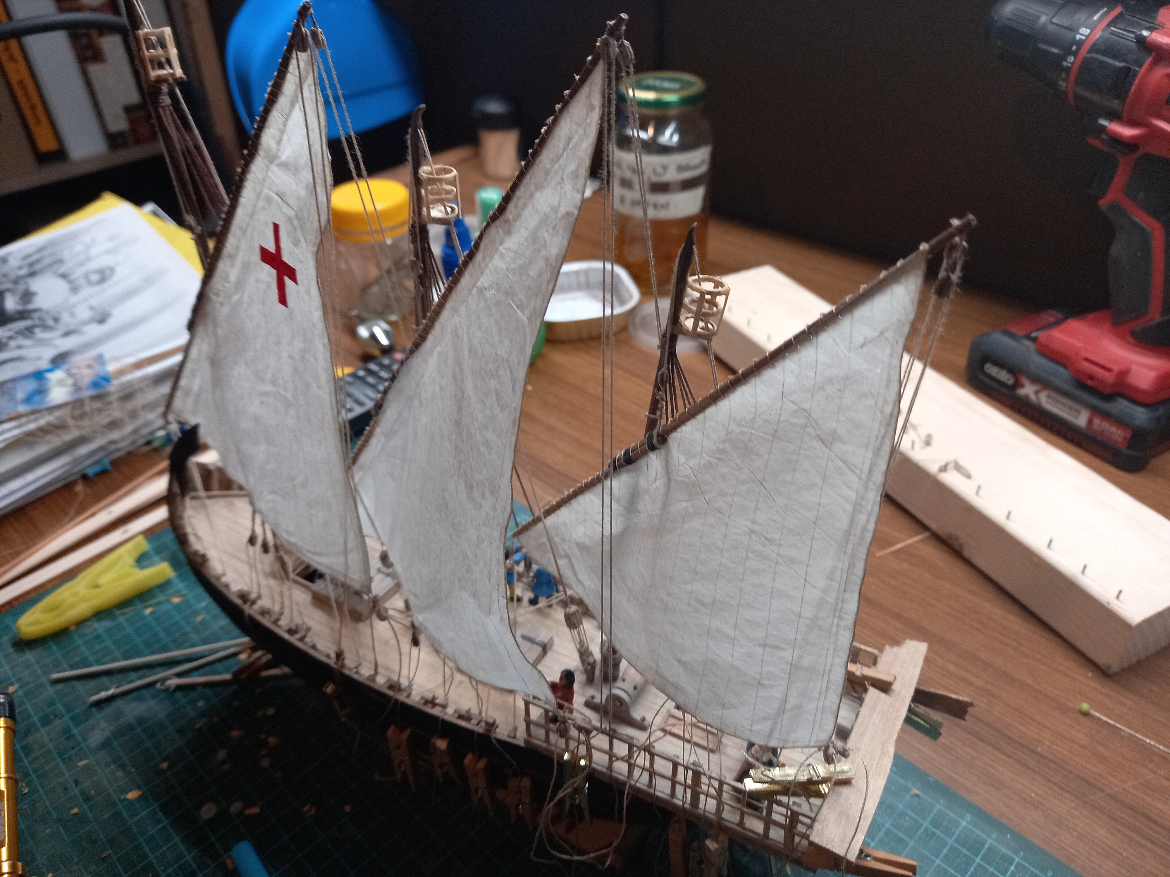
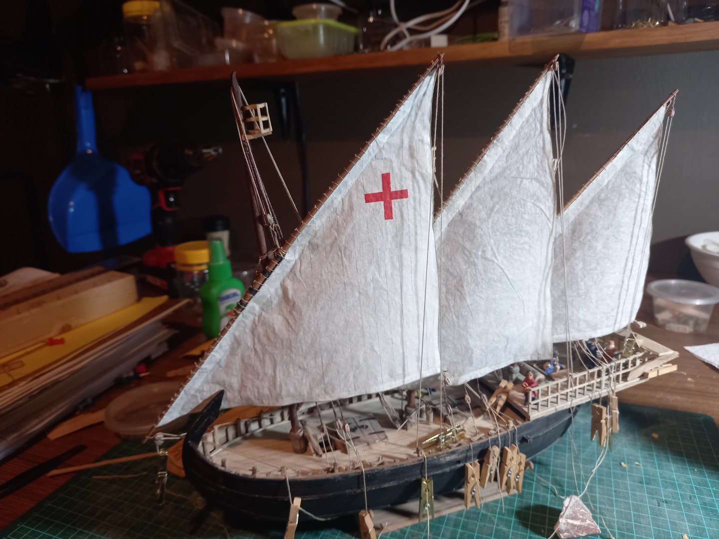
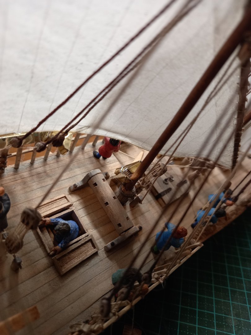
I've been fiddling with the sail of the 'mast of the middle' to get it to 'belly' correctly. The silkspan is impregnated with acrylic paint, so by laying the ship over, wetting the sail, judiciously adding weights, and letting it dry it should retain the shape I've given it. I've only done it to the middle sail so far, and you can see the result here. Not perfect, but not too shabby, either. and then I've been working to get the right configuration of the sheet, which should be a straight line because of the pressure of the wind, but is difficult to do because there isn't any wind. I finally worked out that if I belayed the sheet at one end and then pulled it tight at the block, I could fake the wind pressure by impregnating the sheet with CA and letting it dry. Seems to have worked so far. Steven


- 508 replies
-
- 11
-
-
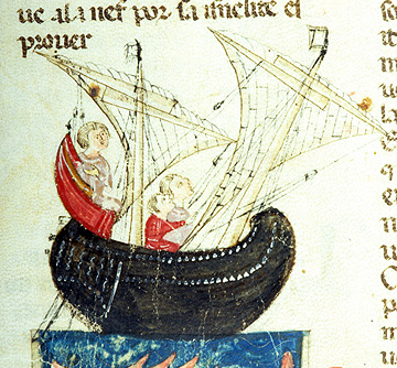
Johnny, It's generally thought the original 15th century model this model is based upon was made far too short and tubby compared with the real thing. It's a votive model - given to a church, usually by a seaman grateful for being saved at sea. Steven
-
Nice. I used to do model railways in a small way when I was a teenager - got partway through building a local West Australian tank locomotive out of tinplate (it would have been OO scale but HO gauge, corresponding approximately to the 3 foot 6 inch gauge that West Australia had at the time. But my skills weren't up to the job, unfortunately. And I had no idea how to make the chassis, add the wheels, motor etc. A pity. I enjoyed the process, though. Yes, I think it would be good for you to put those things up in "Non-Ship categorised builds" - I'm sure I wouldn't be the only one interested. Best wishes, Steven
-
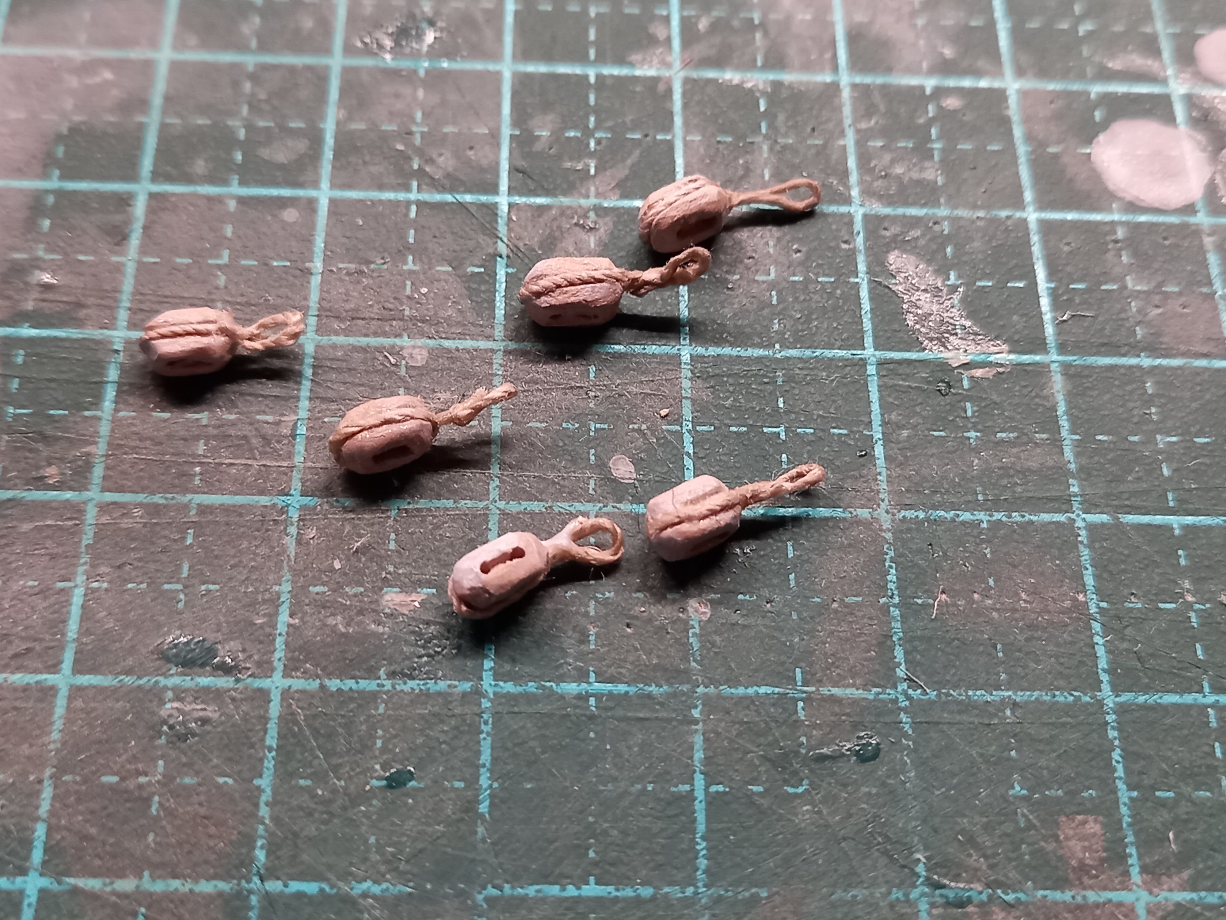
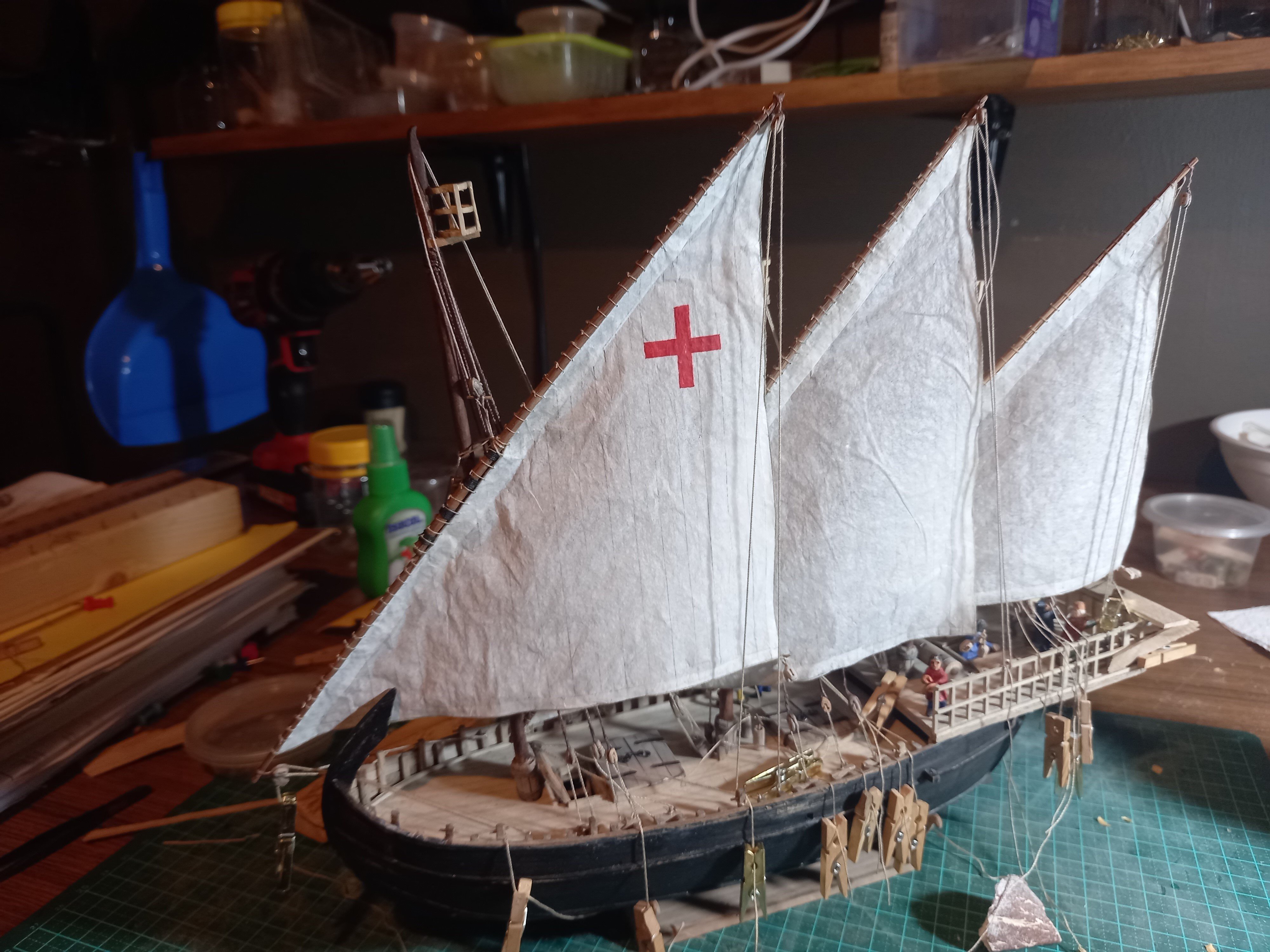
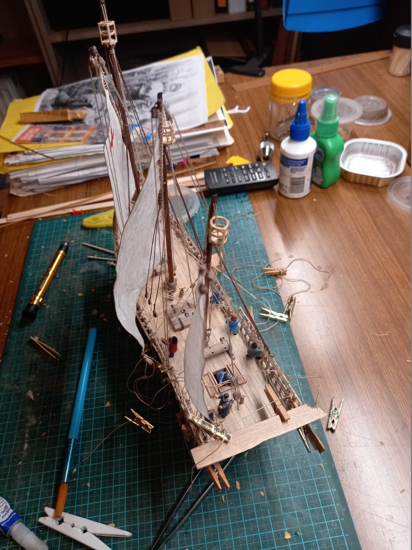
And I changed my mind about the sheets. Originally I'd had them just tied directly to the clew of each sail,with a sheet going off to each side. I decided that threw away mechanical advantage and that there should be a couple of blocks at each clew. But how to attach them? After a lot of thought I went back to the traditional Mediterranean method - a toggle through a loop. So I made two blocks for each sail, each with a loop at the end, and passed the two loops through the cringle at the clew with a toggle to hold them in place. The pictures show all - in the last one (for the mizzen) the toggle hasn't yet been cut to length And I've been adjusting the balance of forces acting on the yards, to get the sails in the configuration I want (for example, the fore end of the central yard was too low, so I had to cut off one of the tacks which I'd already cut to length, and replace it with another longer one so there was enough rope free so the fore end could be pulled up higher by pulling down on the brace/vang at the upper end of the yard (not sure that this explains it very well, but I know what I mean). So here she is in her current manifestation. A bit more fiddle needed - tying off ropes and adding the truss for the fore-yard, things like that. And I'd like maybe to have another go at smoothing out the sails - they're a bit too wrinkled for my liking. Then to finish off the anchors, add the steering oars, re-position one of the crew - and I do believe that will mean I've finished! (unless I've forgotten something!) Steven


- 508 replies
-
- 18
-
-
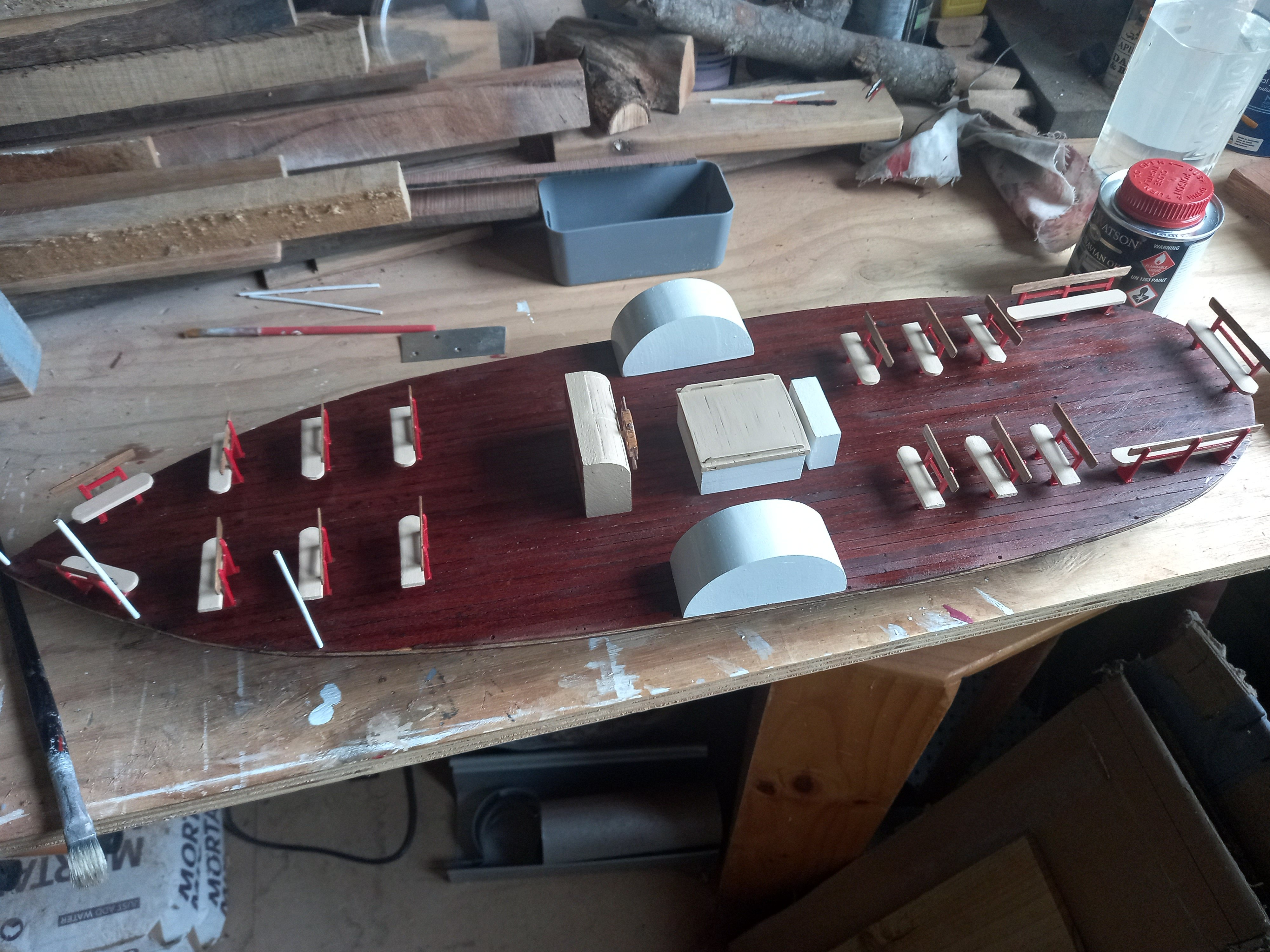
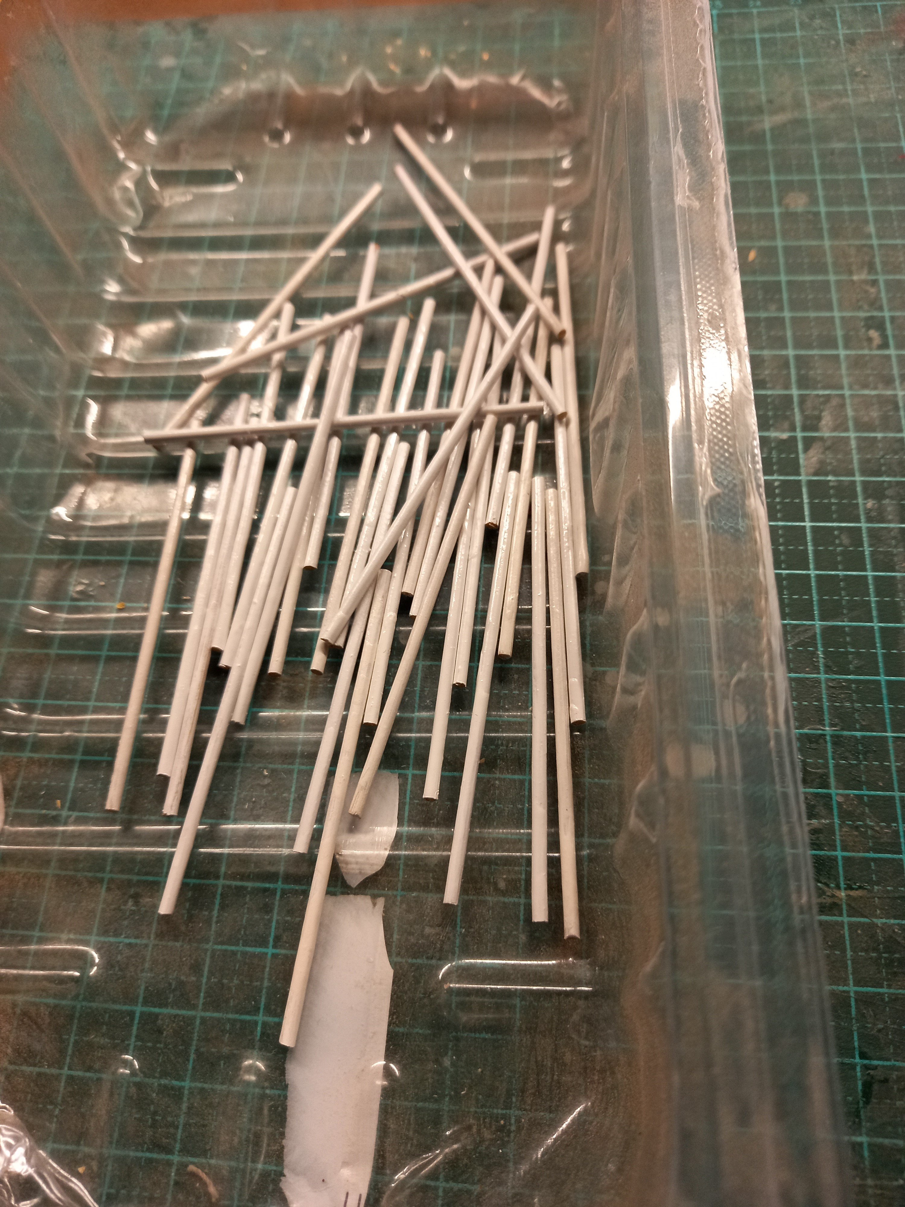
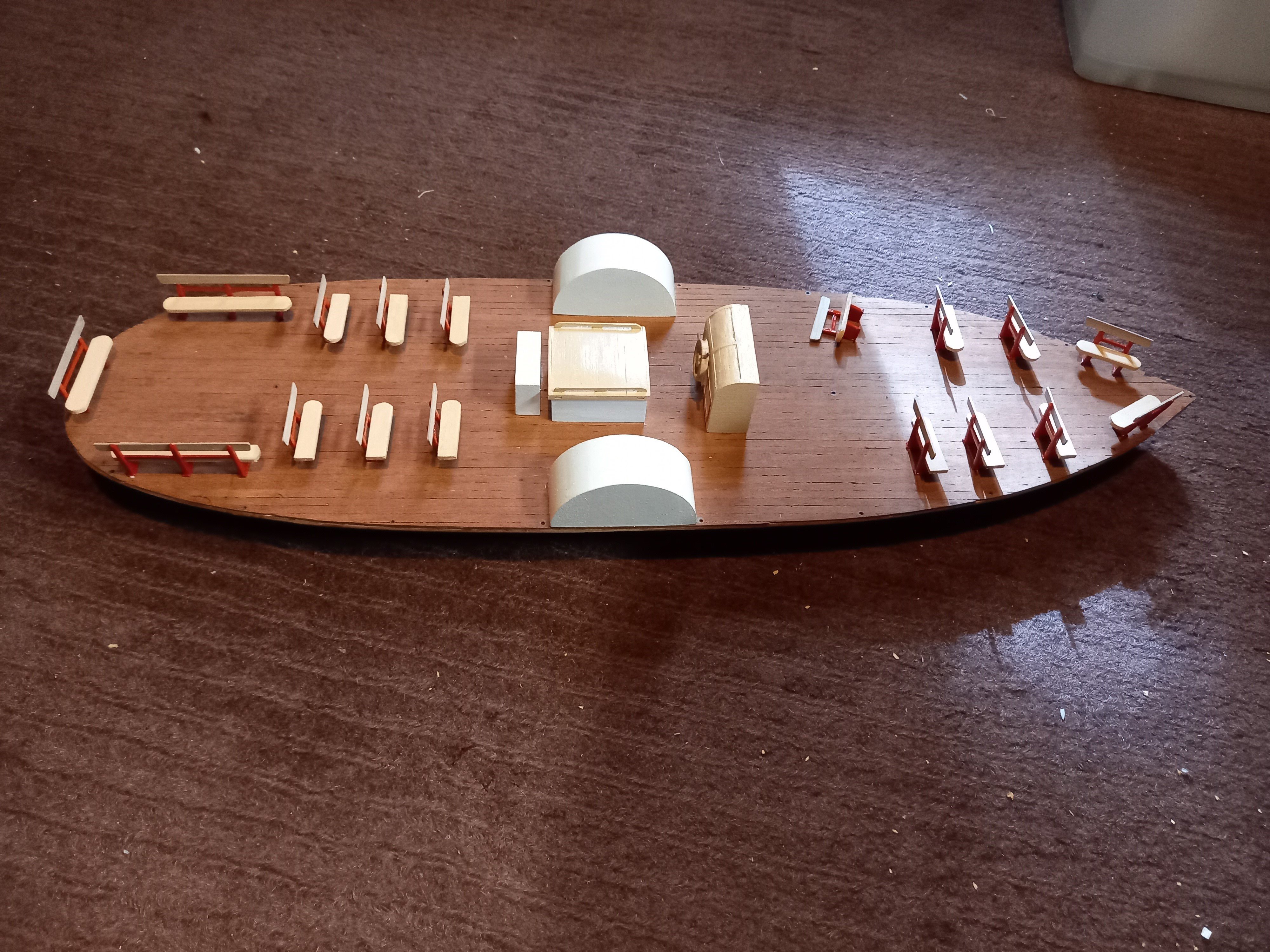
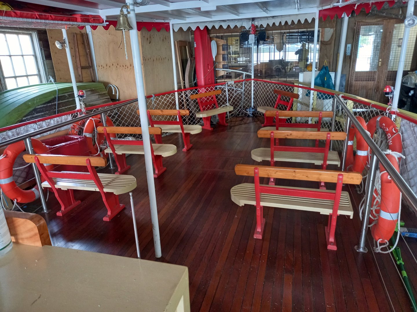
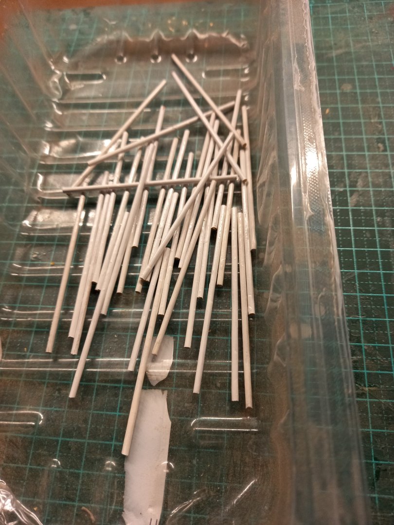
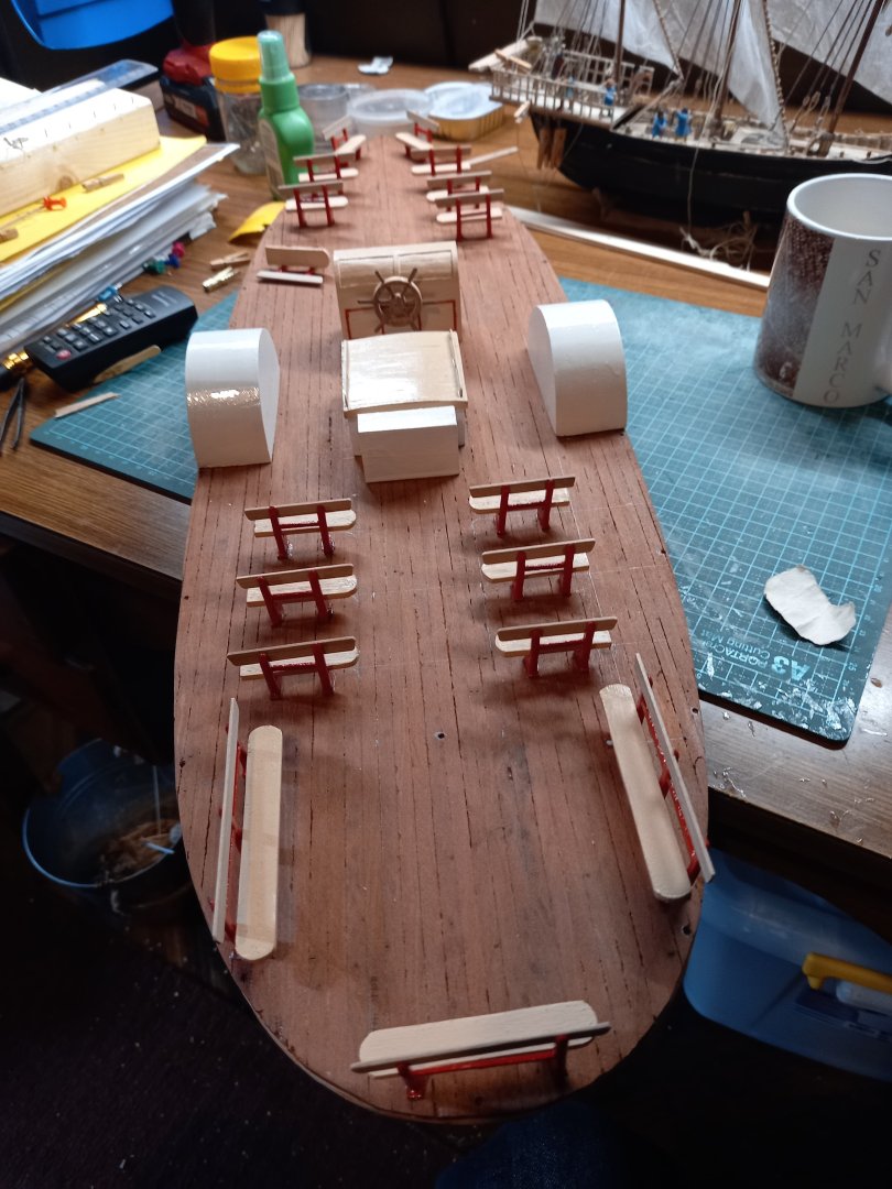
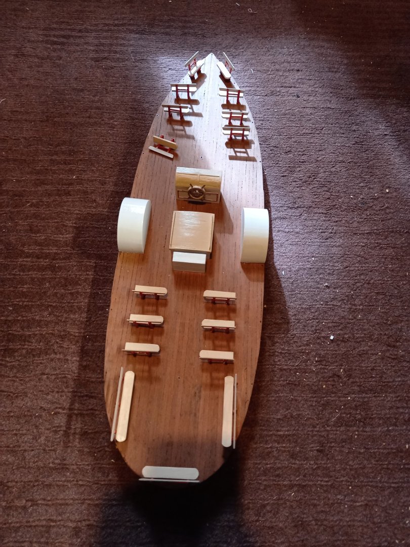
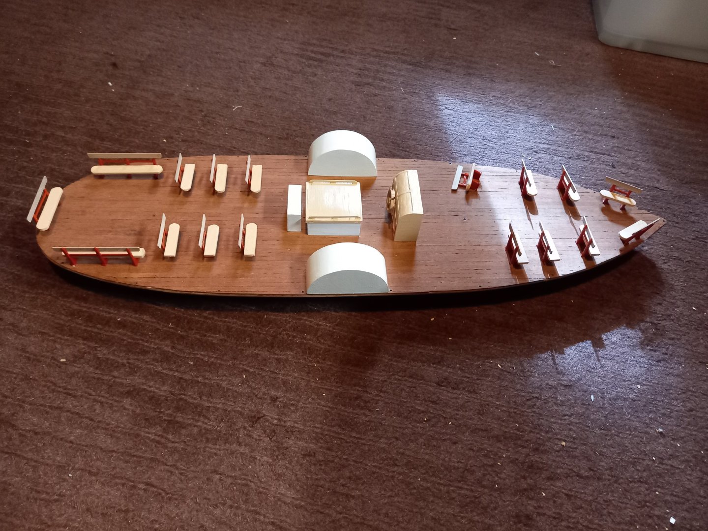
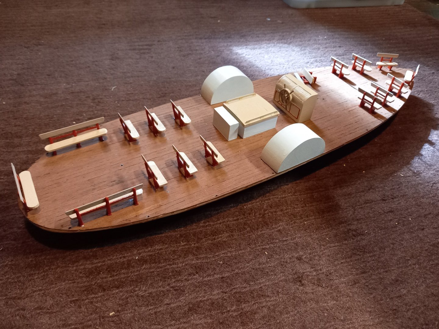
It's been a while since I've posted in this build. I've been recovering from shock. Everything was going swimmingly until I glued the "verandah" to the lower hull, then - DISASTER! I hadn't lined the two pieces up properly and they were out of alignment - not just a little, but enough to stuff everything upcompletely. And as I'd done such a good workmanlike job with the gluing and clamping, I couldn't get them apart without brutalising them. Which I then proceeded to do. As those who've been following this build are aware, it had taken months to plank the verandah, and all that had apparently gone completely to waste. I prised the two pieces apart with an old chisel, breaking off bits from both pieces and ripping up the lower layer of the plywood deck. I thought I'd ruined both pieces, and it took me awhile to recover and regroup. First I cleaned up the lower hull, removing fragments of the upper part that had stuck to it, and bogging up the breaks where I'd wrenched it with the chisel. I still thought I'd have toi make a new upper deck, with all the extra work entailed in re-planking. But after awhile I realised that if I removed the worst bits and made sure it was smooth all around the outside of the area it joined the lower hull, the central section didn't matter, so long as it was clear of the join. I did that last week, and VERY carefully lined it all up and (heart in mouth) glued it up again. And it worked! (sigh) So with a restored hull and deck, I was able to move ahead and start adding the deck equipment and the seats. I added the wheel (see an earlier post) to its housing and stuck down the paddlewheel covers and other deck equipment, as well as quite a few of the seats. So here it is in its current manifestation. The forrard seats aren't yet glued in place, just put there. I have to work out their exact placement before I can stick them down. You can see the holes for the posts that support the awning roof around the outer edge of the deck. She's looking pretty good, I think. I've now cut the posts for the awning. And I've also come up with a solution to a problem I had with the smaller version - location of the posts so they'd line up top and bottom and the awning would stay at the same height throughout. I realised there are three places where there are three posts going across the breadth of the vessel, and if I make three strips of wood to go across the tops of these with holes to locate the tops of the posts, I can get them all the same height and just place the awning on top and glue it down. I haven't done it yet - watch this space! Steven
- 110 replies
-
- 15
-
-
-
- Paddlewheeler
- Ballarat
- (and 3 more)
-
Thanks for the information, Rodolfo. Valuable for us who are interested in carracks, and making models of them. What scale is your railway? You might like to post photos of it in the "Non-Ship categorised builds" section of MSW> I'm sure there would be quite a few people interested in seeing them! Steven
-
You're doing very well, mate. And speed is not an issue in this hobby. Particularly not at the expense of care and precision, which is much more important, and is what you are achieving. Beautiful work. Steven
-
This is coming along very nicely. Your skills are improving from one model to the next. Nice work, mate! Steven
- 176 replies
-
- 1
-
-
- la reale de france
- heller
- (and 2 more)
-
You've done a beautiful job of this, mate. Congratulations on a superb model! Steven
- 55 replies
-
- 1
-
-
- miniature
- Brandenburg State Yacht
- (and 1 more)
-
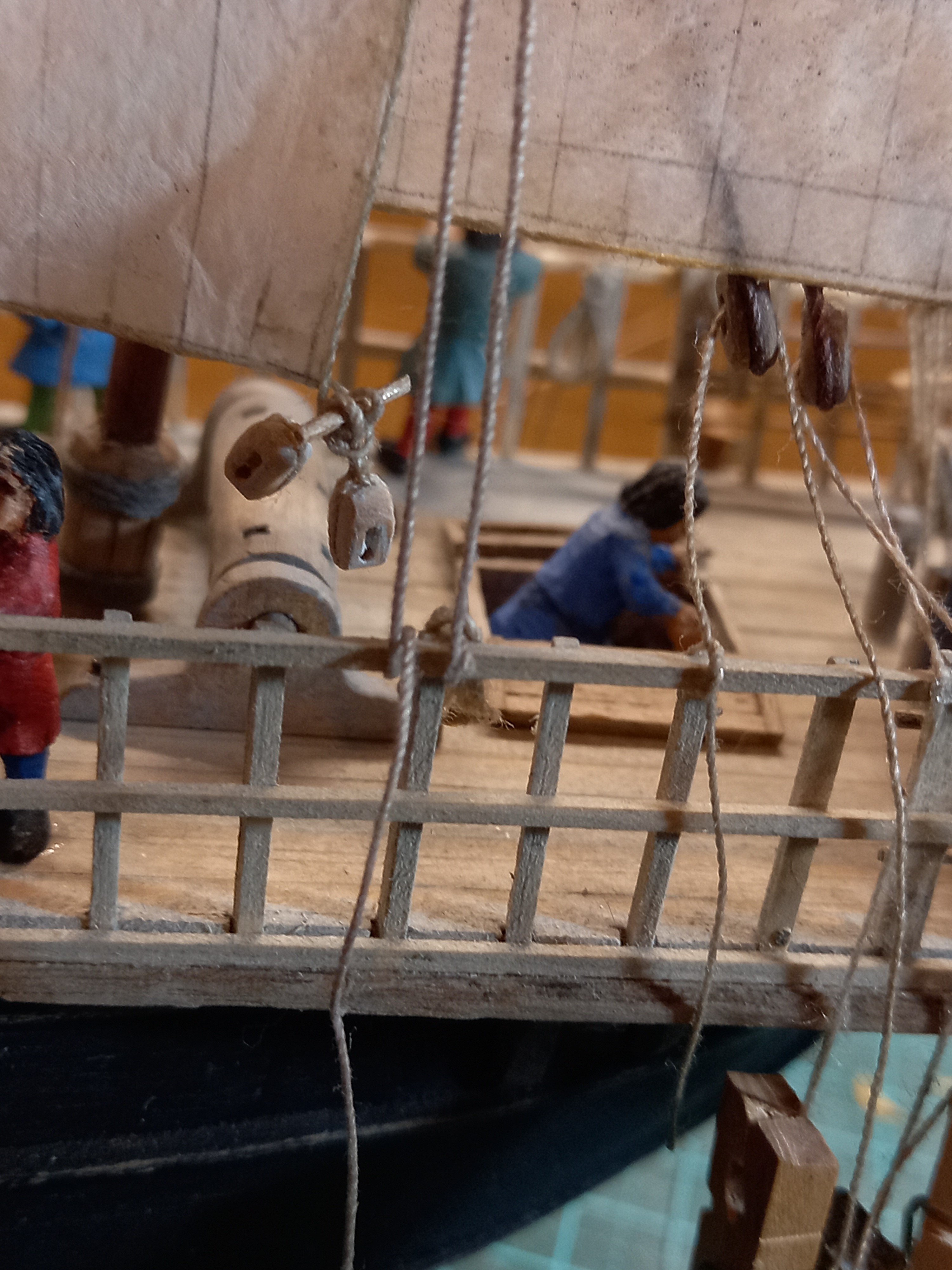
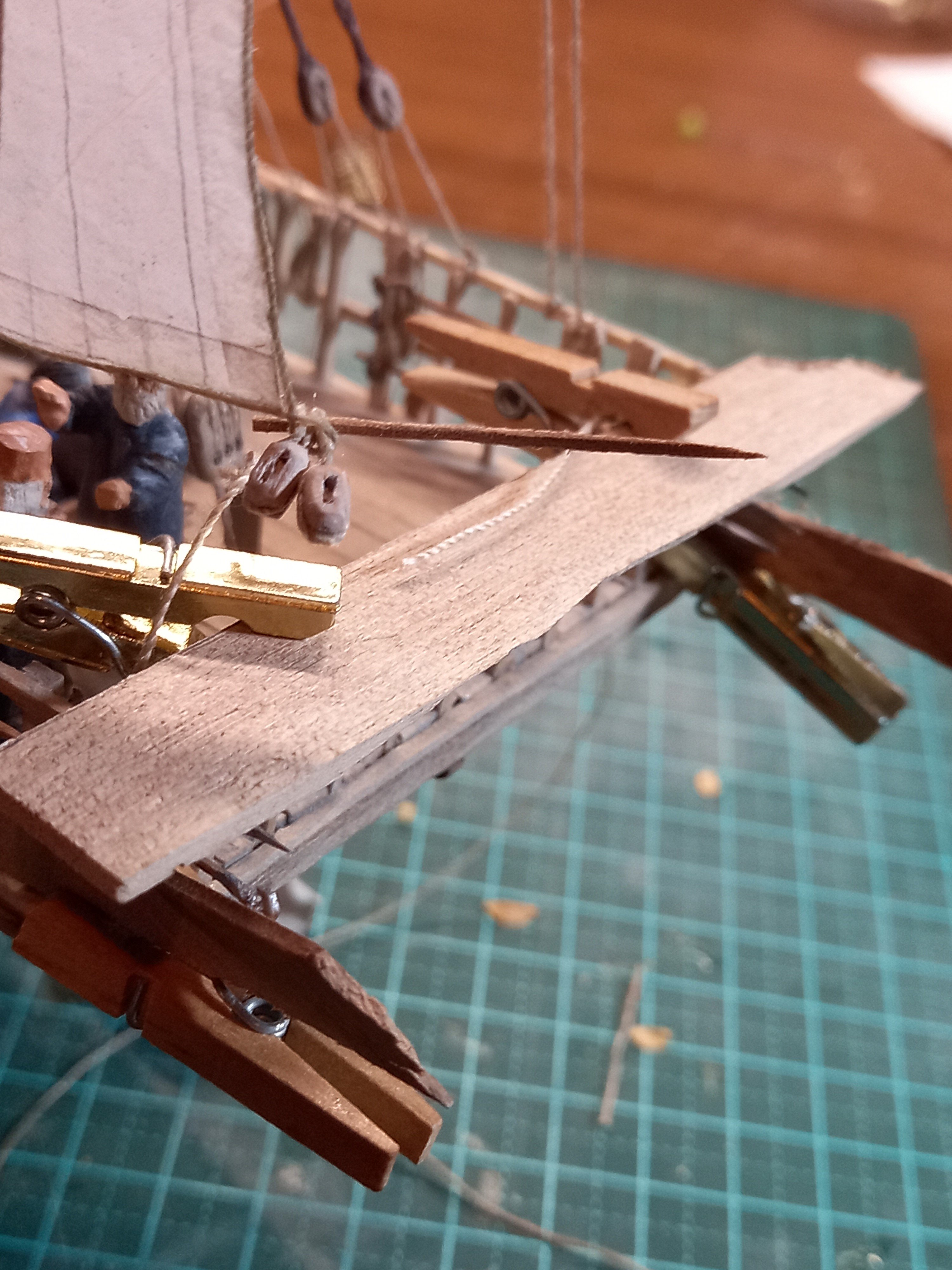
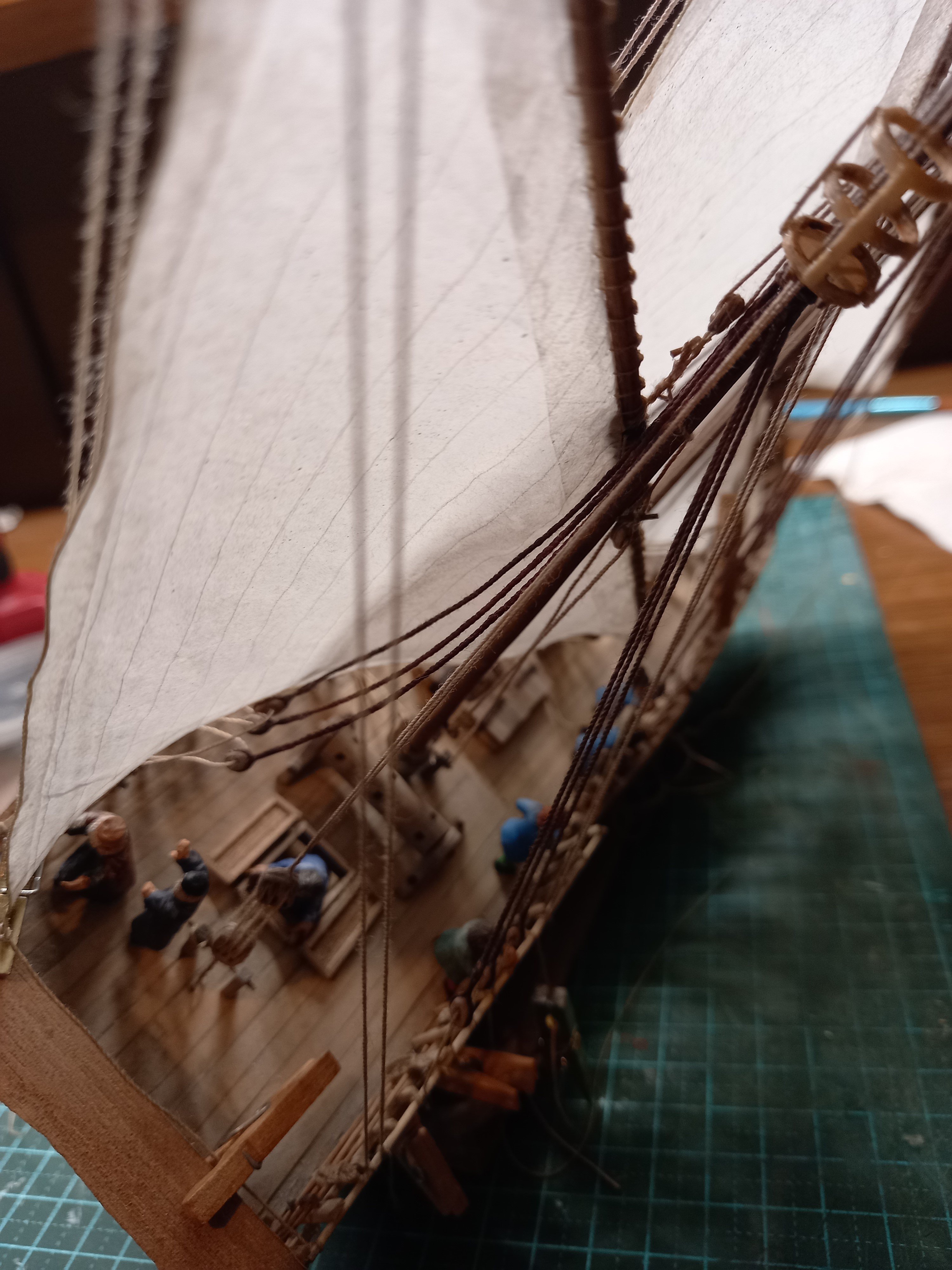
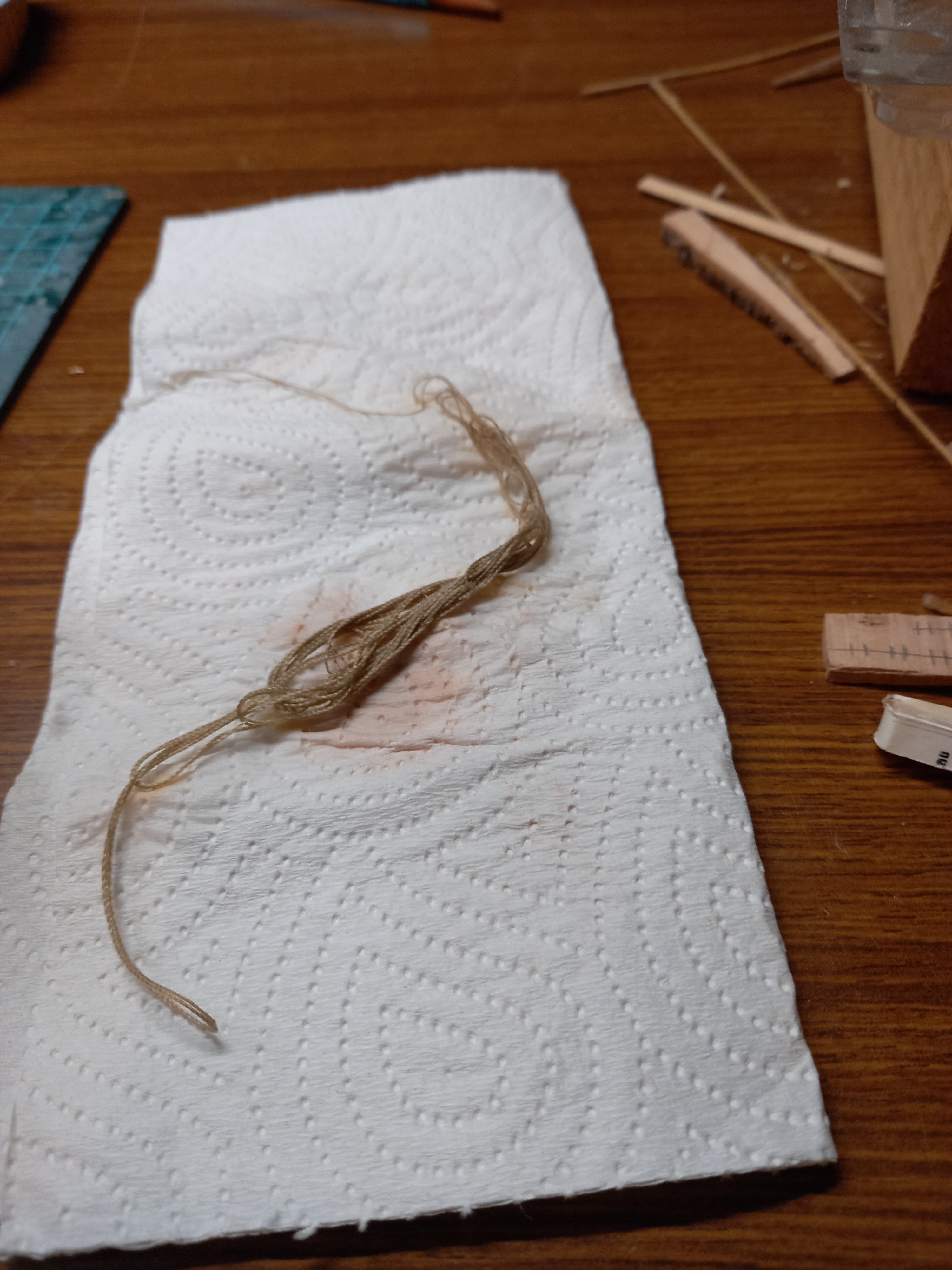
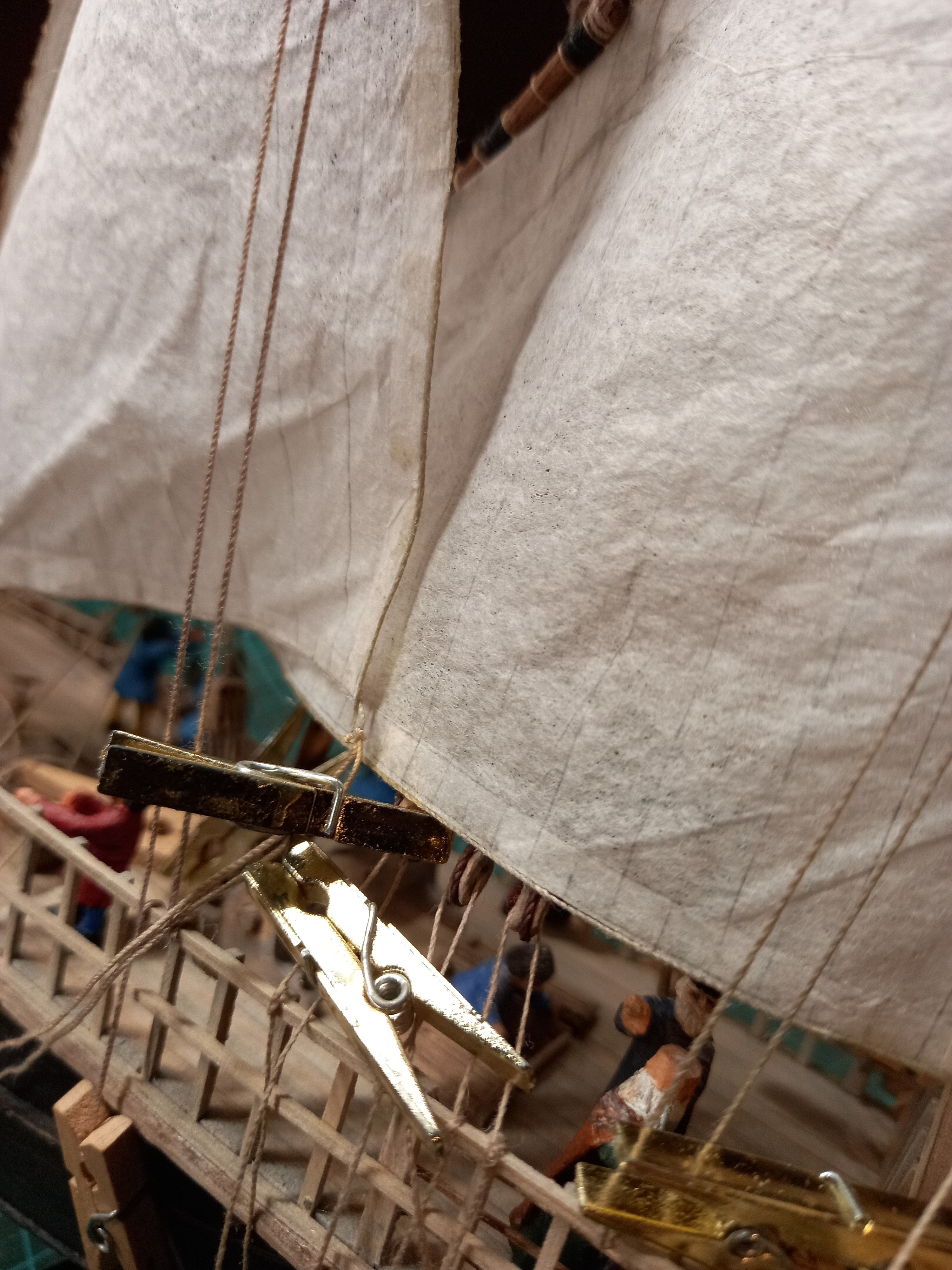
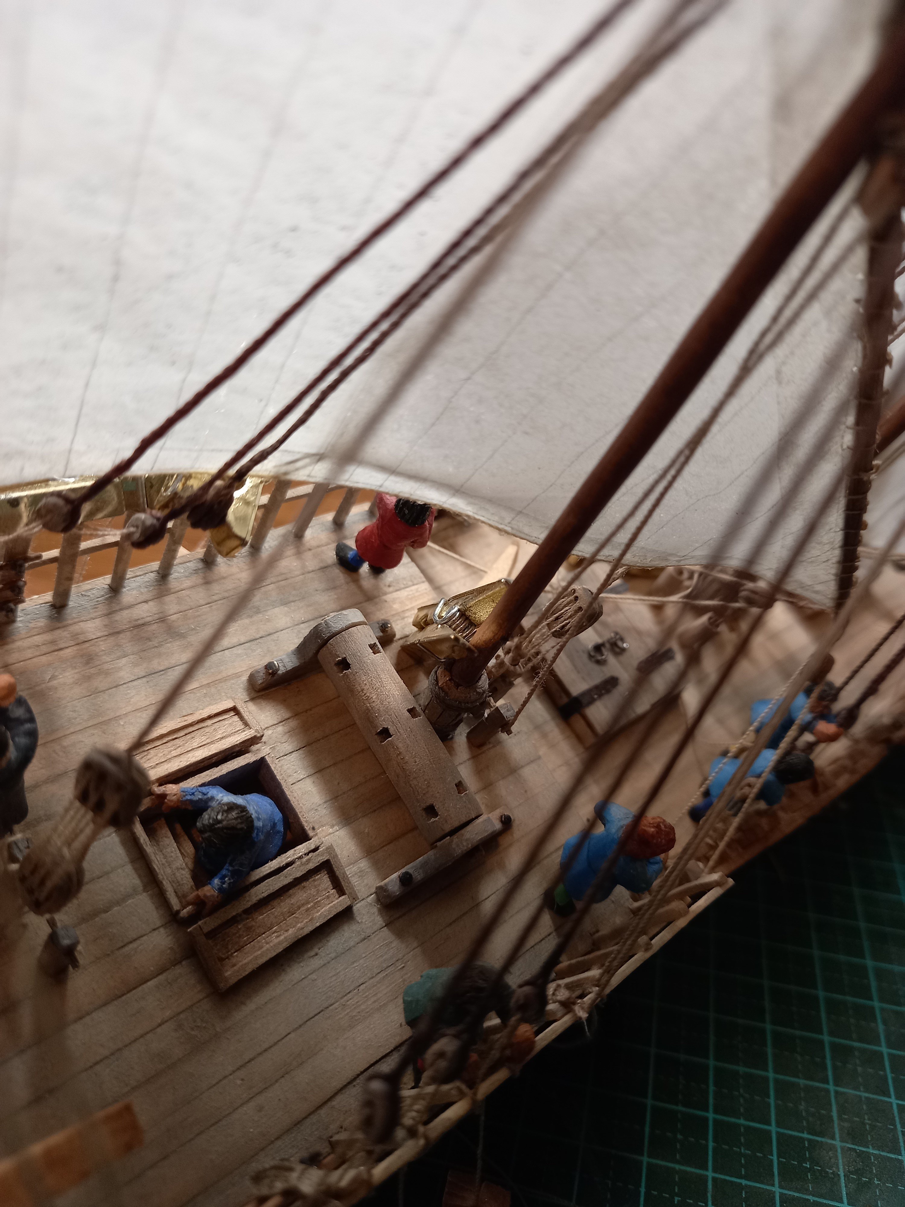
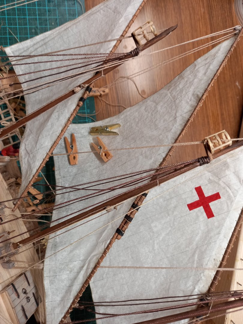
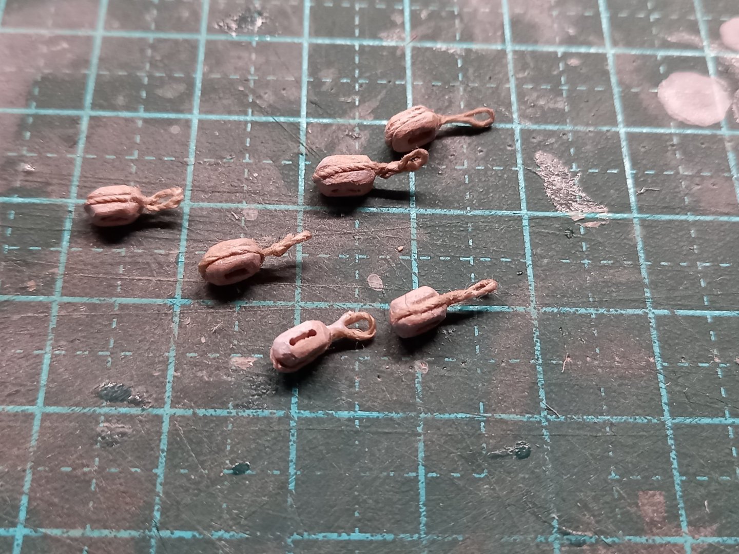
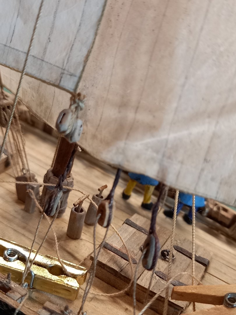
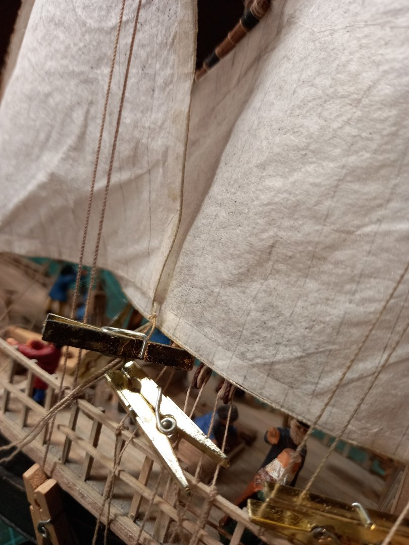
Thanks everyone for the likes and comments - Ian, much obliged (blush). More progress. Starting to run out of tan thread for the tackle, so I dyed some more white thread (soaking it overnight in a mix of green, light brown and dark tan fabric dyes. Works well). As the shrouds on the lee side are loosened off, I needed to give them a nice catenary curve, showing the effect of gravity on a long rope. Not all that easy, because it's not a long rope, it's a short piece of heavy thread, and retains its 'bounce' against gravity. So first I tilted the model to get gravity happening, then used a watercolour paintbrush with a mix of water and PVA (white) glue to soak the shrouds - per advice from a MSW member in n earlier post. This made them hang in a natural-looking curve. Once dry they kept the curve. Next the lanyards for the blocks had to be given a catenary curve as well. Same problem, same solution. Tilted the model sideways, soaked the thread in a water/glue solution and used a tiny clamp (a gold plastic clothes-peg - the one on the left in the photo) to hold the sides of the lanyard to the block so it wouldn't bow out unnaturally, and used another peg (the right-hand one) as a weight to force the lanyard to take a catenary curve. It's just the right amount of weight and did the job nicely. And here it is from the other side - you can just see the jaws of the golden peg around the right-hand block, just below the foot of the sail. This is the first time I've tried using dilute glue to force a catenary curve on ropes. I was very happy with the result.


- 508 replies
-
- 10
-
-
-
Ghastly things. I learnt drafting using these and I have nightmare memories of a huge black blob of ink dropping onto an all-but-completed drawing . . . aargh! But maybe that's just me . . . Steven