Louie da fly
-
Posts
7,993 -
Joined
-
Last visited
Content Type
Profiles
Forums
Gallery
Events
Everything posted by Louie da fly
-
Great footage, Mark. Good to see the budgie smugglers getting an airing, too . . . 😁 Steven PS: I used to live a short walk from the beach at Coogee. Nice memories.
-
Yes, to reduce leeway when the ship can't have a deep keel because it works in shallow waters. Here's a Humber keel using one (thanks Lightflite!) - check out from about 20:15 onward. Steven
-
 Better, certainly. Walnut's better than pine, but still not my first choice for carving. See if you can get hold of some fruit wood. It's worth it. Though I have to say that's one pretty Duyfken! Steven
 -
That's all looking very good, Doug. I like the paintwork, very neat. And you have the narrow white stripe between the red and the yellow. Very nice. That works nicely. Arches seem to have been a bit of thing at this time, so I think you've got a pretty good justification for it. Oh, do it if you possibly can. You do know they've actually found the original, don't you? https://maryrose.org/artefacts/emblem-figurehead/ If you're worried about carving it, don't be. That's just a matter of practice. And using the correct wood (fruit woods are nice and fine grained - pear, apple , cherry. Or better still English box - buxus sempervirens - that's amazingly good). Have ago! Carving can be very rewarding and fulfilling (and addictive if you're not careful!) No, there's no need. I made the mistake of not even including the decks at all in my Great Harry (hey, I was seventeen - I didn't think ahead far enough) and had terrible trouble supporting the cannons inside. I had to do all kinds of dodgy work to make it happen. Never again. But there's certainly no need to have planking on a deck that nobody will every see. Very nice. Yes, that's a bit of a mystery. I don't think it's an open railing, which was the first thing that came to mind, as it doesn't continue around the stern. But the transom is not the same as the sides - it has to be solid to support the spar that takes the lateen sheet, so maybe that is an open railing after all. But yes, there is a narrow line of stripes above it. Perhaps a broad, painted top rail? I know McElvogue has shown a wooden support structure in his book, but I'm pretty sure that's speculative - I don't think anything was actually recovered. But I'm pretty sure the remnants of netting he shows are the real thing. I'd say, however, that his idea is practical and is quite probably what was done. Have a look at the "boarding frames" - that is, sort of pergola things that served the same purpose on earlier carracks. McElvogue's design is similar, but with the 'rafters' further apart, which would be sensible as the netting takes the place of the intervening rafters to act as a barrier to boarding. The main issue I had was - how do you deal with the problem of belaying all your rigging lines if a boarding netting is in the way? They normally belay either to the side of the ship or close to the relevant mast, and it's probably possible to work it all out. But you'd have to think it through well in advance so as not to paint yourself into a corner. To be honest, I had been planning on a boarding netting on my Great Harry, but I chickened out - it all seemed too difficult. Though that was at 1:200 - yours at 1:80 shouldn't be as hard. Steven
-
You're using the wrong wood, mate. You've actually done a very nice job - the little dove looks good - the talent is there but that woodgrain is far too coarse for this kind of fine work. Get hold of some fruit wood - pear is good, apricot is better. If you really want the best wood for fine carving, get hold of some English Box (buxus sempervirens) - it's incredibly fine and wonderful to carve. And keep on practising. If you're not satisfied with it, have another try until you are. It's worth the extra work to have something you feel good about. Steven
-
Beautiful work, Olli. High quality and very precise work. And her beautiful lines are now starting to become even clearer. Steven
-
I love watching your work, Patrick. That forecastle is looking magnificent. And very believable as a practical piece of 'equipment'. Looking forward to your shields. As someone who's used shields in re-enactment combat and made quite a study of them, if you want any help with their historical accuracy, feel free to ask. Steven
-
Yes, my experience with oak was instructive. I knew the issues regarding grain, but the pieces I had seemed to be considerably finer than the usual run-of-the-mill oak you see around the place. But even then it turned out to be too coarse for the work I was asking it to do. I agree about fruit woods. My previous models have used (mostly) walnut and sometimes pear for finer things like deck furniture, blocks etc. I've discovered that apricot wood is finer grained than pear (we cut down an apricot tree in our garden - it was being attacked by some sort of parasite and couldn't be saved, but the wood was ok). And we cut down a big plum tree in our garden as well, and I got the wood, but I haven't tried using it yet. Yes, green oak is far easier to work, and in fact I've seen freshly cut oak used - for example in house building (I watch Grand Designs) and in the replica of the Sutton Hoo ship that's under construction at the moment. By the way, you think oak is hard and tough, you ought to try working with some of the Australian hardwoods! Karri in particular is incredibly tough. Steven
-
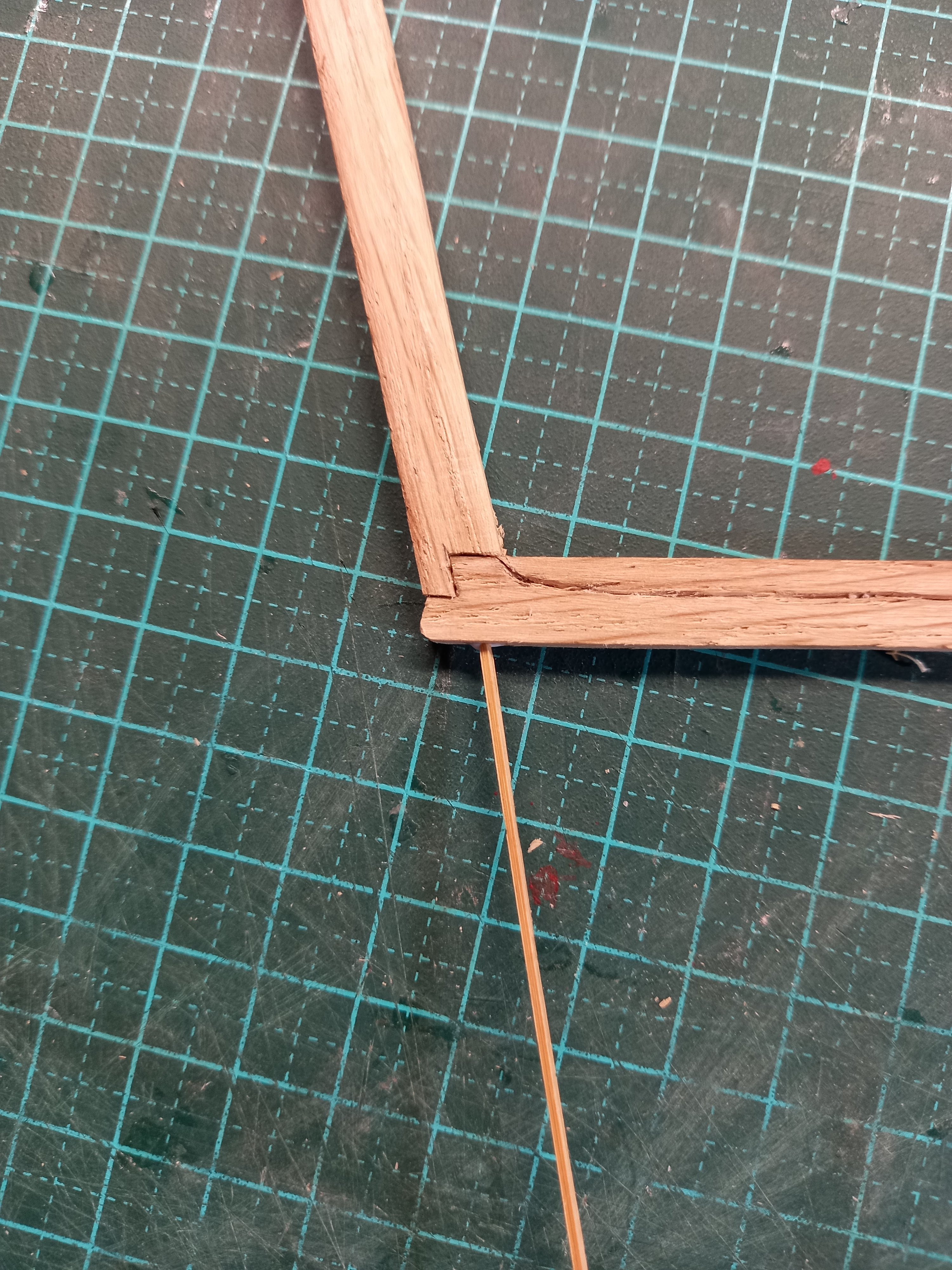
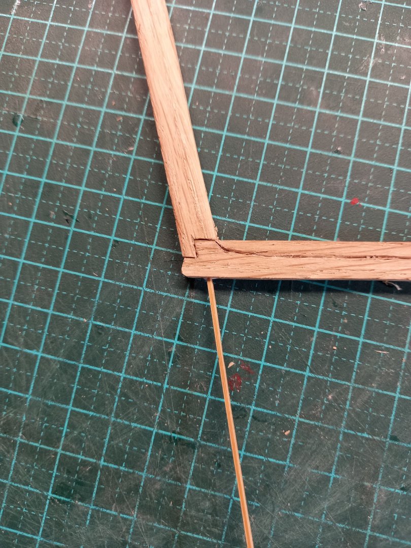
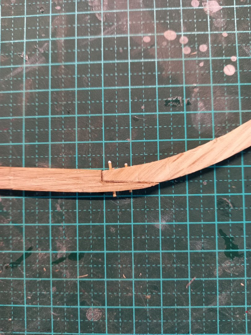
Reinforcing the joints between the keel and the stempost and sternpost. I drilled holes through the joints then inserted bamboo pegs. It made the joints much stronger - I don't have to worry now about snapping them off in a moment of inattention. I've started carving the rabbet, but the oak grain is really not fine enough to do this well, and I'm considering starting again with a different timber, perhaps walnut or plum, which will take the rabbet better. Steven
-
Very appropriate. What the Vikings would call Orm - a "worm" (serpent/dragon). At the battle of Svolder King Olaf Trygvasson had a longship called the Serpent (Orm) and another, bigger one called the Ormurin Langi (long serpent). Steven
-
Interesting thought. To me it looks as if the two at far left and far right are level with each other, both at the front corner of the 'cabin', and the rear one is at the back corner (starboard), but that leaves the question 'where's the one for the port back corner?' Or it could just be that he bunged flags wherever he could fit them. I dunno. Up to you, mate, whatever you feel is right. It's your model, after all. Best wishes, Steven
-
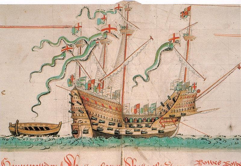
Keep in mind that these reconstruction drawings are modern interpretations, and I for one can't see any evidence to justify these 'prows'. I like your way of doing it far better. I think the angle of the bowsprit looks far closer to the Anthony Roll depiction than those of the two modern reconstructions. So go with it. The height of the bulwark above the deck - one metre - is what is specified here in Oz for any structure such as a railing on a raised floor/balcony etc. So I think you're on the money there. The triangular 'cabin' surprised me a bit. I would have thought the Anthony Roll shows the walls parallel to the sides of the forecastle. But this is very open to interpretation, and I'm by no means going to say you're wrong in doing it this way. Overall, I'm gobsmacked. You're doing a beautiful job! Steven
-
Nice. Steven
-
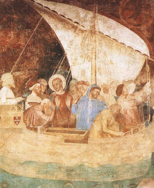
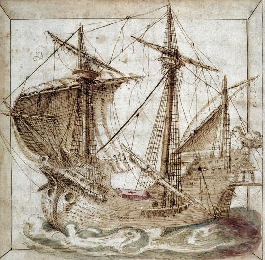
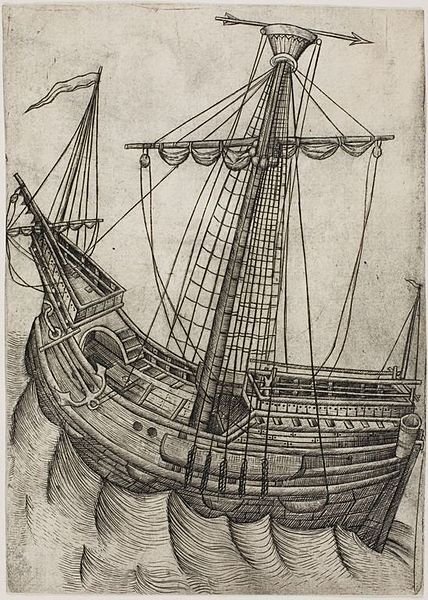
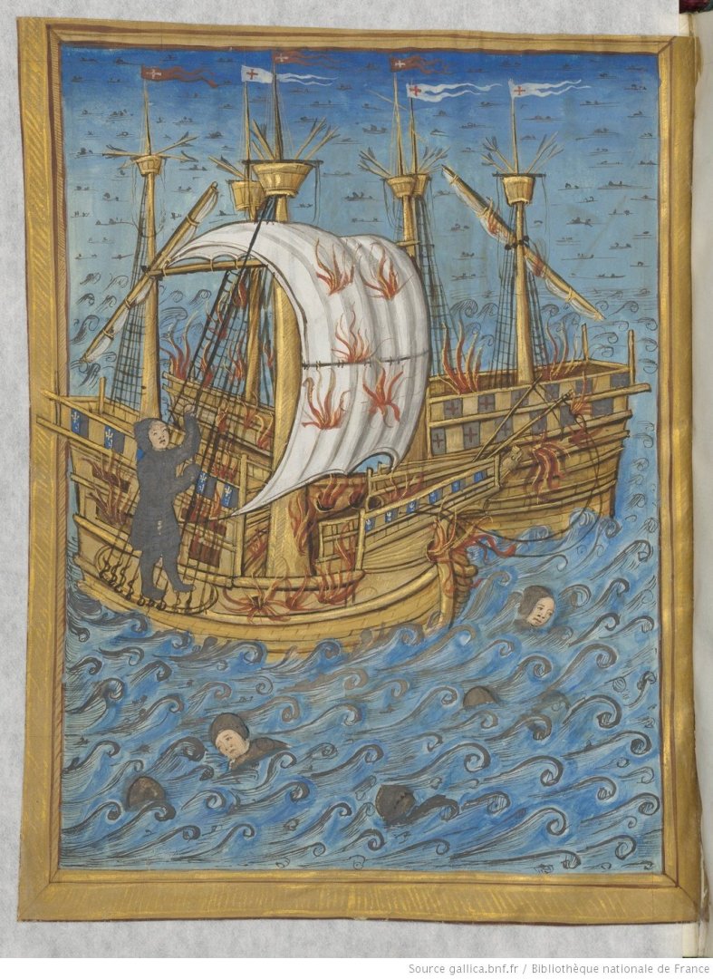
Yes, unfortunately the Botticelli Judgment of Paris picture (and, for that matter his Punishment of Korah - he just seems to recycled the same ship) is the same - no hatch covers. I read somewhere that the 'pierced' hatch covers made of criss-cross battens were a fairly late development, intended to allow gunsmoke to disperse. But I don't know what evidence that conclusion was based on. The 'removable planks' idea - I think Viking ships used that technique (don't quote me, I'm not sure), and I first saw it on a model of Woodrat's. Unfortunately the information just isn't out there as far as I've been able to find. Contemporary images hardly ever show ships from a helpful angle, and if they do, the hatch is often shown without a cover - oh, look! another one that's no help at all . . . no cover on the hatch. I feel like the guy leaning over it - frustrated. Andrea di Bonauito de Firenze - Conversion of st ranieri Camposanto of Pisa - mid 14th century after a 13th century Giotto original And is this a hatch cover or a coffin? (sorry, I don't know the source) And is this a multi-plank hatch cover? Or something completely different? 1475-85 by 'Master W with the Key' - Netherlands? And how about this one? 1514-1515 Le_combat_de_la Cordeliere by Pierre Choque bnf btv1b525080522 and archaeology so far has been no help as almost all wrecks are missing the upper works. However, the Black Sea wrecks might be a worthwhile source of information, as they seem to be pretty much intact - maybe the hatch covers are intact, too. Might be worth following up. Steven Steven
-
Good to know, mate. I realised I'd not been in touch and had no idea how things were going with you. I hate it when people just seem to drop off the forum and you never know what's happened to them or if they're still out there. I'm glad you're enjoying reading the build logs (including mine!) - I find a lot of enjoyment simply doing that even when I'm not actively building. You don't have to build to enjoy being on the forum. I'm currently at a bit of a slow patch, not sure what is my best next step. And sometimes I have to just stop and let things percolate mentally before I know what is best to do next. (OTOH sometimes I rush into things without thinking them through enough first, but hey, I never said I had to be consistent). Good to hear from you. Best wishes, Steven
-
Yes, much better. I don't think the pine is s problem. The windlass looks very nice now. Steven
-
That appears to be a windlass. And yes, replace the plywood. Here's a photo of the windlass on the full-size reconstruction vessel - https://www.sea.museum/en/whats-on/events/sail-on-duyfken I hope that helps. Steven
-
Waldemar is correct. Oak planking was used where a strong timber was structurally preferable; the rest of the planking was of pine. Mark, at the moment I probably have enough oak to get me by, so I won't ask you to go to all that trouble. But I might get back in touch with you later. We'll see how it goes . . . Steven
-
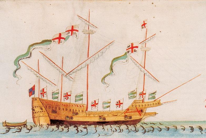
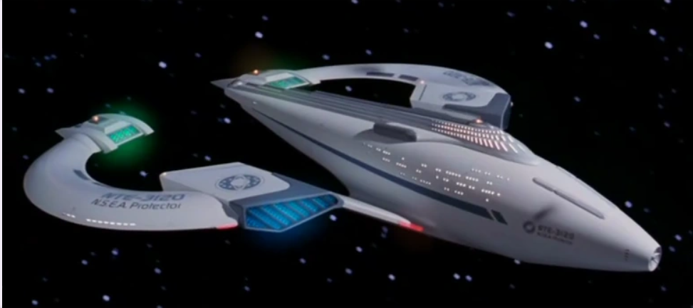
So many things. A "galleass" from the Anthony Roll (not a Mediterranean style oared galleass at all - a sort of low version of a galleon) Brunel's Great Britain, a reconstruction from a graffito in Hagia Sofia cathedral in Istanbul, the Grace Dieu of Henry V (not to be confused with Henry VIII's Henry Grace a Dieu), HMS Captain (which turned turtle and sank in a gentle squall because of her bad design, taking the crew - and the designer - with her), HMS Thunder Child from H.G. Wells's War of the Worlds, HMS Sophie from Master and Commander, a Maltese luzzu, perhaps an Australian pearling lugger, a French pre-dreadnought, an Indonesian fishing boat, a galleon from 1545, one of the earliest carracks from a church pew-end in England from 1415, an early Mediterranean carrack from before the shape had been "tied down", another Mediterranean mediaeval merchant ship . . . the list is endless. And perhaps the NSEA Protector from Galaxy Quest. And of course the Liberator from Blake's Seven. Steven

- 176 replies
-
- 3
-

-

-
- la reale de france
- heller
- (and 2 more)
-
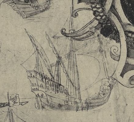
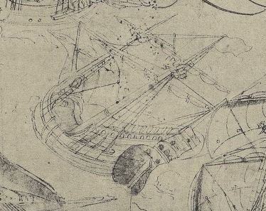
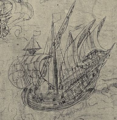
How about one of the more complex ones? These are all from a map of Normandy from 1545. I've had the first one on my bucket list for years. Steven
- 176 replies
-
- 3
-

-
-
- la reale de france
- heller
- (and 2 more)
-
You've done very well with her. Turned out beautifully. So - what's next? Steven
- 176 replies
-
- 2
-
-
-
- la reale de france
- heller
- (and 2 more)
-
Hi Tarbrush, just wondering how it's all going. Best wishes, Steven
-
Very nice work. You're producing a beautiful model of a beautiful ship. Steven