Louie da fly
-
Posts
7,991 -
Joined
-
Last visited
Content Type
Profiles
Forums
Gallery
Events
Everything posted by Louie da fly
-
 Thanks, guys. All I now need to do is paint the name on the nameplate and stick it onto the stand and she's finished! Steven
- 110 replies
-
- 4
-

-
- Paddlewheeler
- Ballarat
- (and 3 more)
-
Not going to happen, mate. I've done all I want to on this one. I'll be glad to draw a line under it without adding anything else to do. Time to get back onto the Lomellina! Steven
- 110 replies
-
- 6
-
-
- Paddlewheeler
- Ballarat
- (and 3 more)
-
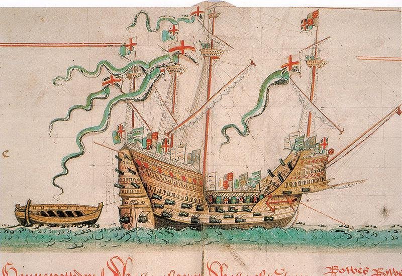
I've planned to make a model of the Lomellina for over 6 years now, since I found out about her. But she was discovered in (I think) 1979 and the excavation was done over the following decade. Yes, there's just not enough of the ship left to know the bow shape - at the bow only the keel survives. So it has to be done by educated guesswork - extrapolated from what does survive. And extrapolation of this magnitude is risky - it's impossible to know for sure whether or not you've selected the correct curve. Though I don't have access to the contemporary text the author quotes, I have spent a lot of time looking at many many contemporary representations of carracks, and I believe I have a pretty good idea of what the bow shape should be. You make a good point regarding the guns and the wheels, but I believe Max Guérout is correct. Apart from anything else, why would they make wheels for field guns but leave them incomplete, without iron tyres? If they were needed in a hurry they would have had to wait till the tyres were made and fitted, which seems unlikely to me. Regarding spaces for gunports, the bottom of the gunport that was discovered was level with the top of a stringer which they have marked as S1, and though the ship had come to rest at an angle of 45 degrees, with the mud above it preserving much of the starboard side, unfortunately there was not a lot surviving above S1. On examining the drawings I thought I'd found another gunport in the region of the master frame, as the frames and planking seemed to be cut off in a straight line there, which argued for an opening - though it was one frame (about 500mm) narrower than the gunport that was found. However, Max Guérout sent me a photo of the relevant part of the ship and unfortunately I had to come to the conclusion that I'd been wrong. And most of the rest of the surviving hull is preserved far enough above S1 that there seems to be hardly anywhere for any other gunports to be. I believe the statement 'very well armed' has to be taken in context. Up till the very end of the 15th century, guns were light, as they had to be mounted on the gunwales. So at this time, a dozen guns would have made the ship 'very well armed'. Her predecessor (also called Lomellina) sank in 1503 and I'm of the opinion that the owners would have had a replacement built as soon as possible, so I should think she was probably built in 1503 or maybe 1504. And gunports were so new at this time that I'm quite prepared to believe that they were very wary of them, and that it's very likely that they only had one per side (as shown in the illustration above of the fleet outside Genoa) and that the other guns were located on the upper deck, pointing over the gunwales. Which necessitated larger wheels to lift them high enough to do so. This seems to have been the case with the Mary Rose - each gun had its wheels individually tailored to raise the muzzle high enough for use. That information about the mast protruding from the water 2 canes is useful to me. The water is 18 metres deep, so the height of the masthead (assuming the mast remained complete) above the seabed there would be 21 metres. But she came to rest at 45 degrees, so we would have to multiply the mast height above the seabed by 1.414 (the tangent of 45 degrees) and then allow for the depth of the hull as well. Taking into account all the uncertainties built into this assumption, this might still give a fairly good estimate of the height of the mainmast. I've worked it out by proportion from contemporary pictures, and it will be interesting to see whether the two figures agree. Thanks for the good wishes, and the offer of translation help. Interestingly, I recently joined a French conversation group here in Ballarat, and for the first time about a week ago I was able to read a full paper in the original French (with occasional journeys to Google Translate for words I didn't know). But if I find myself at a loss, I'll keep you in mind. And now, enfin, I've started making sawdust. Here's the stempost (not recovered by the archaeologists), and the piece of wood from which the keel and stempost will be made. As all the segments of the keel except one were found (and they know the length of the gap where that segment used to be), I think I will be making my keel out of four pieces copying the real ones. The sternpost wasn't found either, but they have a good idea of its size and angle. Best wishes, Steven

-
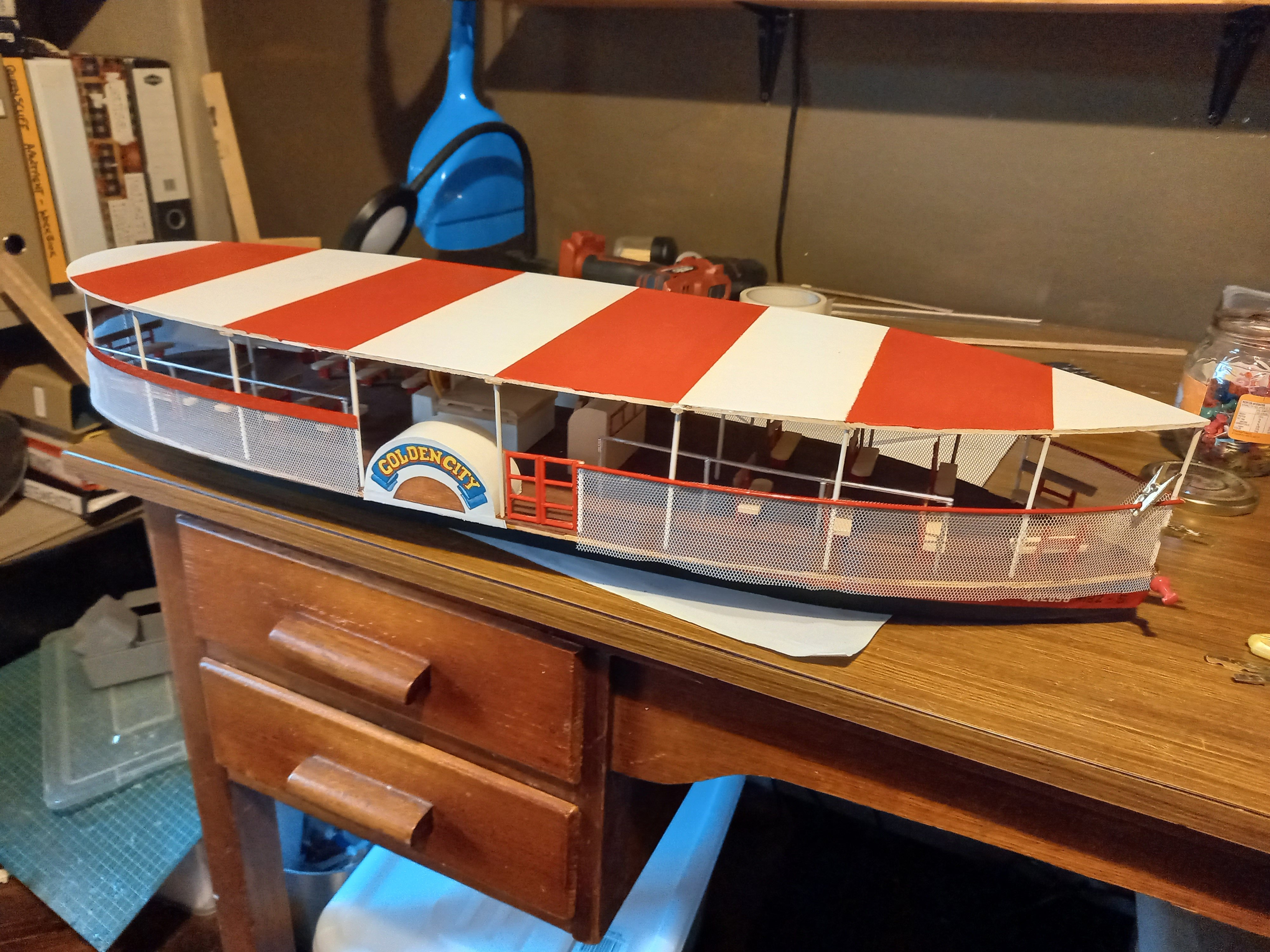
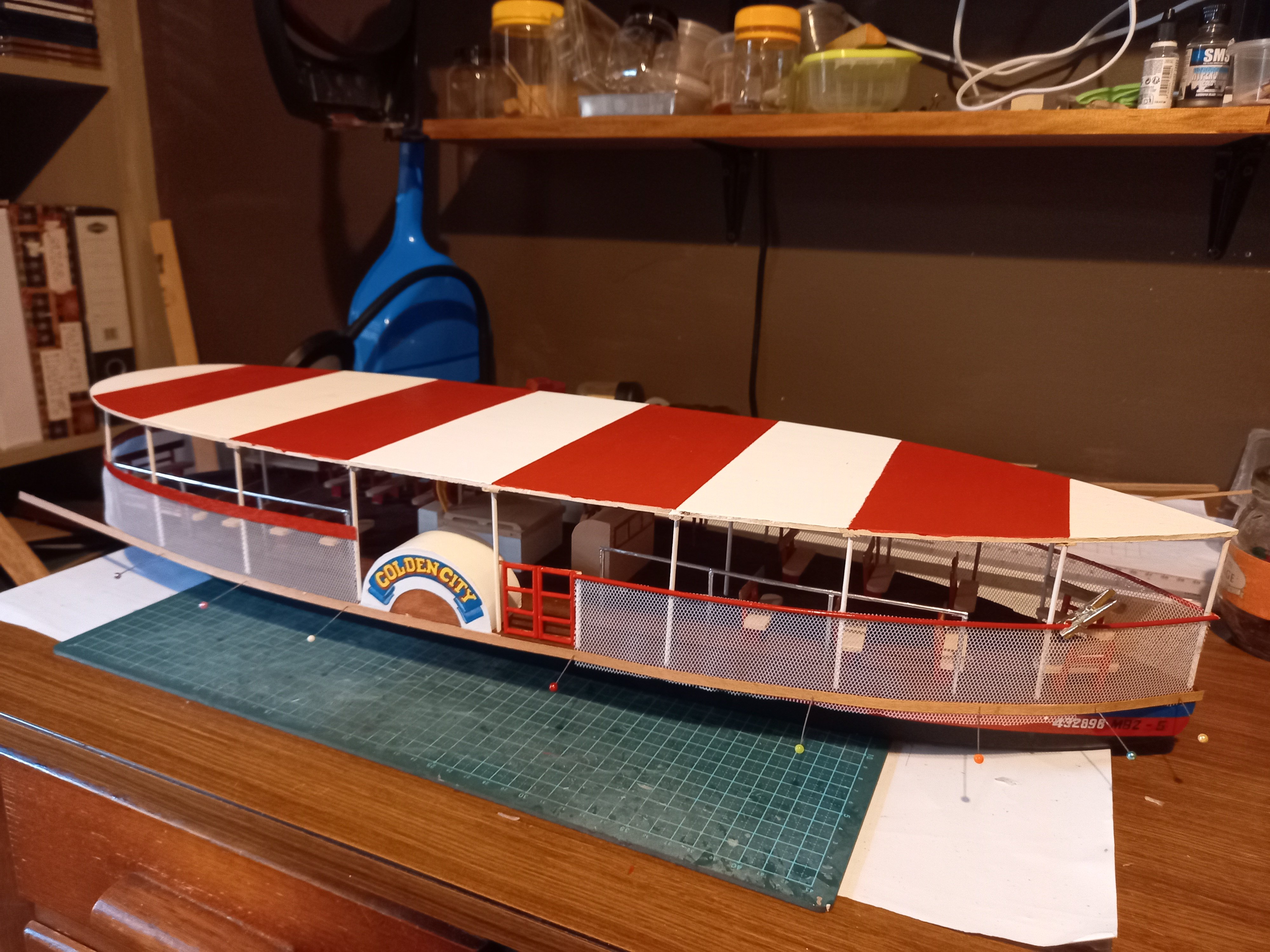
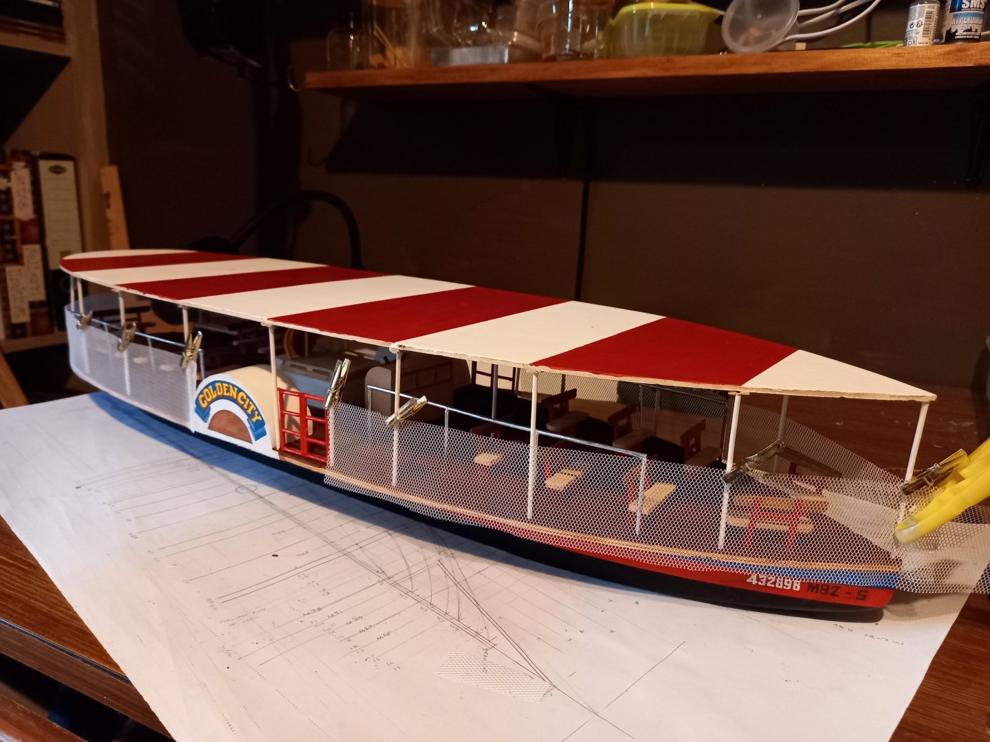
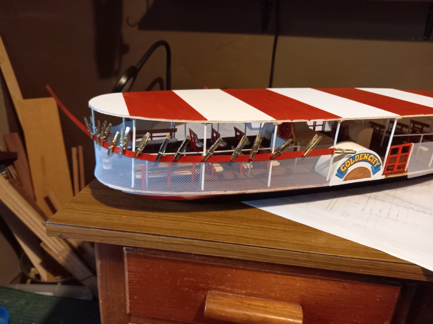
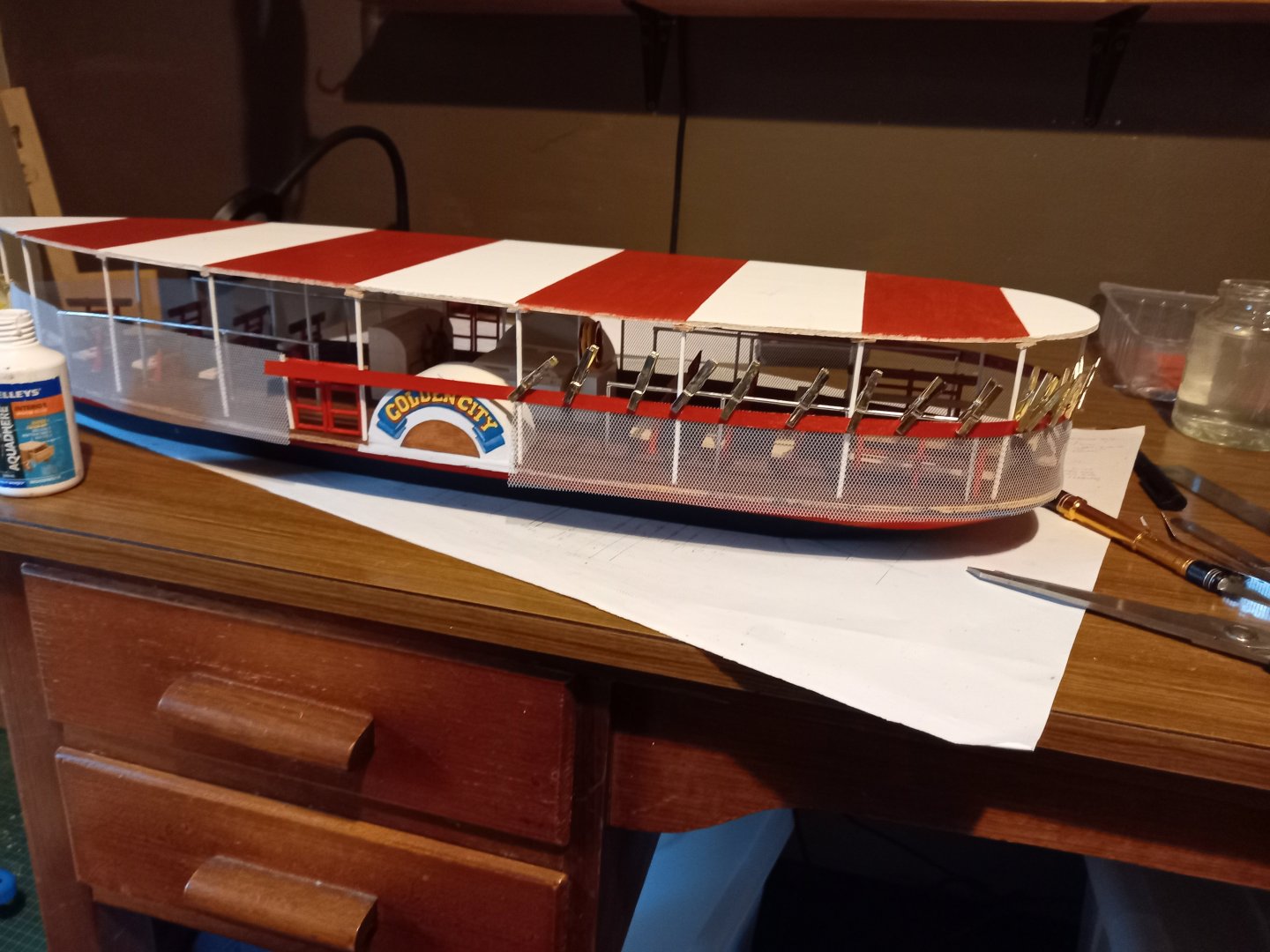
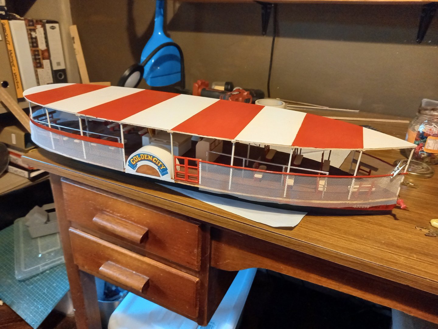
Added the wavy border of the awning. And painted it. Some kind of brace for the paddlewheel housing. Dunno what its function is. Maybe to help with vibration? And the ship is now on its stand, waiting for the glue to dry. And you can see the paddles in this shot. And views from different angles. I still have to add the rudder and a label and then she's complete. Steven


- 110 replies
-
- 15
-
-

-
- Paddlewheeler
- Ballarat
- (and 3 more)
-
From my own reading, the general British attitude has been that it was a disastrous and very embarrassing loss for Britain. Steven
-
A very pleasing curve, very well executed. Steven
-
That's looking very good, Patrick. Beautiful work. Steven
-
I think you're right, Patrick. The Pilot's cabin seems to be fairly close to the ship's side, and if the staircase is behind it, it makes sense there'd be another one near the other side of the ship. I think there would have been an enclosed walkway - between the aft wall of the Pilot's cabin and another, parallel, sloping wall some distance behind it, which is also the rear wall of the forecastle. And the stairs would be between these two walls. But there'd have to be enough room between the aft wall of the Pilot's cabin and the aft wall of the forecastle to allow for people to walk past the opening in the deck for the staircase - so perhaps the forecastle would have extended about 2 metres behind the back wall of the pilot's cabin? The staircase seems to be somewhat inboard, and that would make sense - there appears to be a walkway between the pilot's cabin and the side of the ship, which would serve the side-gunners. And this would perhaps be mirrored in the forecastle. By this time ships may or may not have had the 'great arch' any more - you can't tell because the boarding netting and its gangway are hiding that part of the ship, but above that just a relatively small arched opening for access from the gangway that supports the netting, as you've shown. And you'd walk through the arch and into the walkway behind the Pilot's cabin. And the rest of that enclosed space between those two walls would allow room for the gunners of the rear-facing guns (which the Anthony Roll shows at the ends of the forecastle rear wall), as well as of the men serving the sideward facing guns, who would work in the fore-and-aft walkway. That's my thoughts on the matter. Steven
-
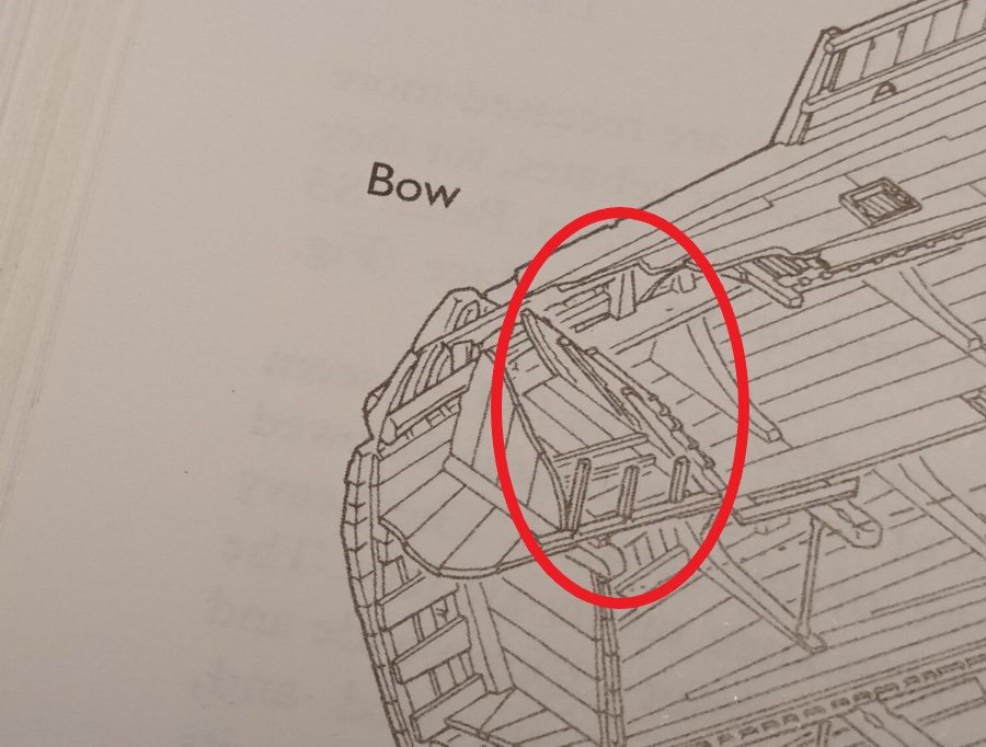
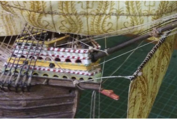
Patrick, I think I've found the stairs! I believe that the aft wall of the pilot's cabin is at an angle of 70 degrees and the stairs follow it - that in the red circle we see the Pilot's cabin, and that its aft wall is indeed inclined at 70 degrees, and the stairs can be seen on the other side of that wall, with the treads running from side to side, up the aft side of that wall. And if that's the case the forecastle would be directly above the Pilot's cabin, and extending both forward of it, and aft far enough to allow room for the stairwell. And furthermore, I think it's likely that the rear wall of the forecastle would also be at 70 degrees, and would perhaps be only far enough aft of the aft wall of the Pilot's cabin to allow space for the stairwell. Here's the Anthony Roll picture of the Mary Rose, and the aft wall of the forecastle certainly seems to be leaning forward. And it seems to me there'd be room each side of the stairwell for the (light) guns facing aft toward the waist of the ship to defend against boarders. Best wishes, Steven
-
Looking good, Doug. Perhaps you're using the wrong type of gun for the forecastle. I'm PMing you a paper on the range of contemporary guns in use, by Max Guerout, who was in charge of the excavation of the Lomellina. The rest of it looks really good. I'll have to look at my documentation for the distance between decks on the Lomellina, though you should also be able to get info those distances on the remaining structure of the Mary Rose, which would be more appropriate to your build.
-
Getting close to completion. Rigging is always a hassle (though at least it's a little less complex on a lateener). You've done a nice job. Steven
- 176 replies
-
- 1
-

-
- la reale de france
- heller
- (and 2 more)
-
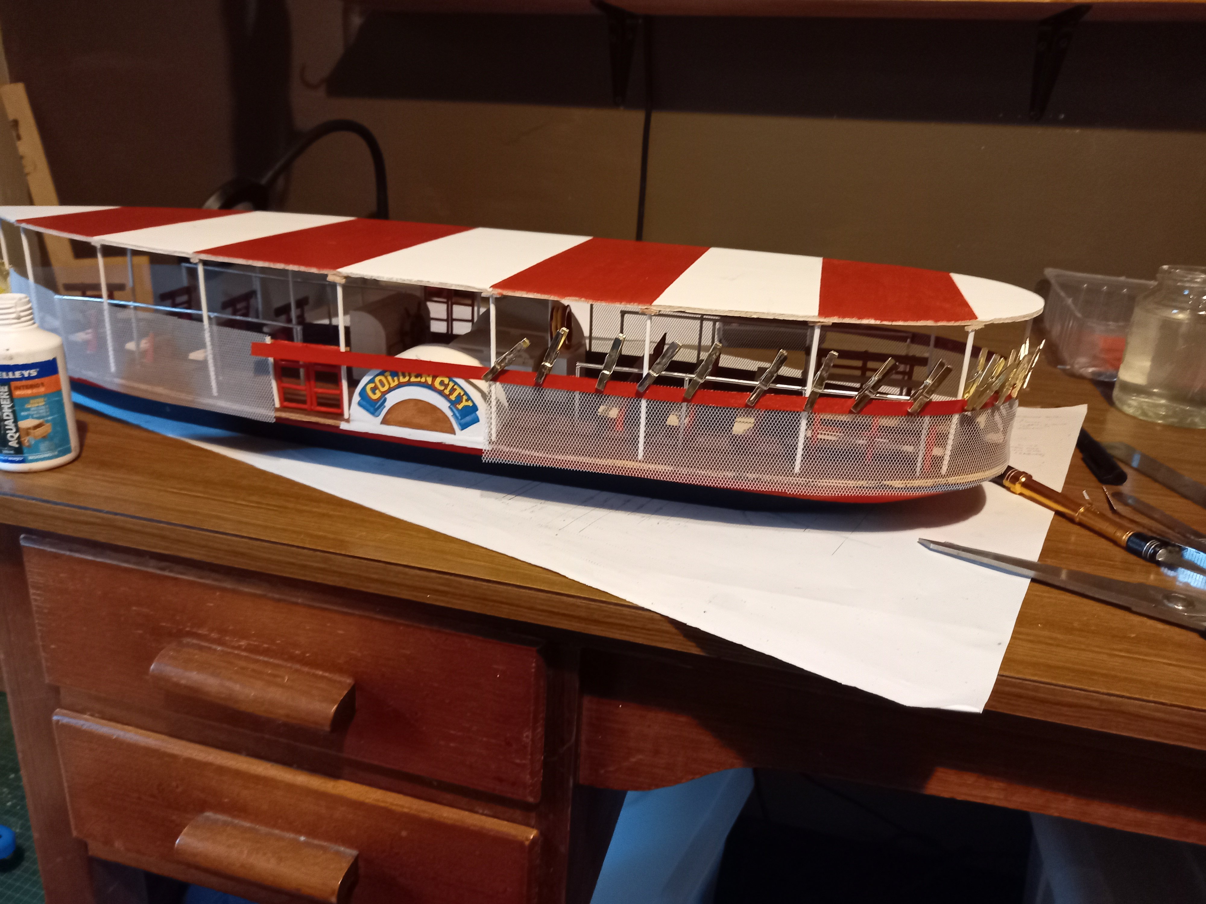
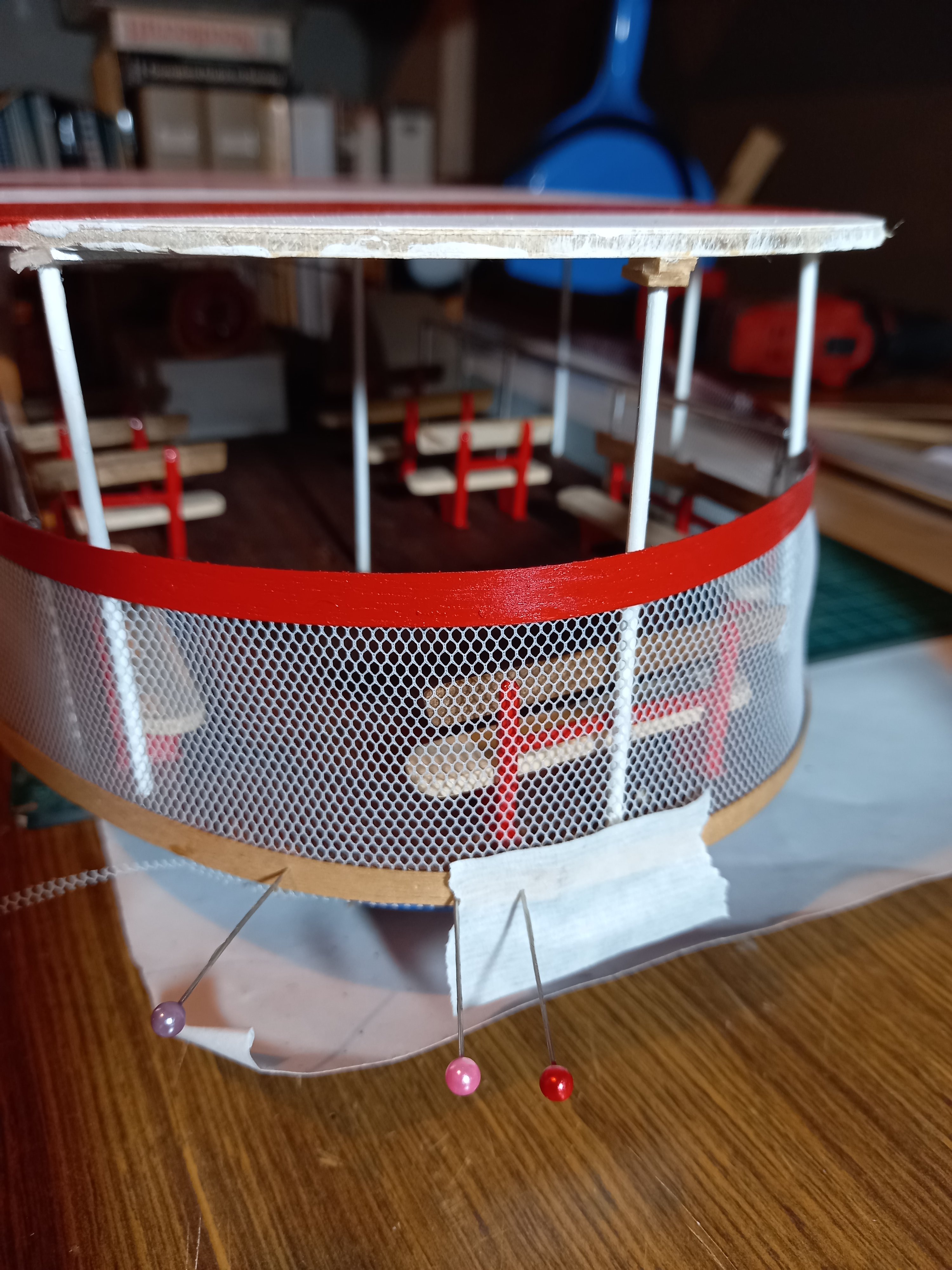
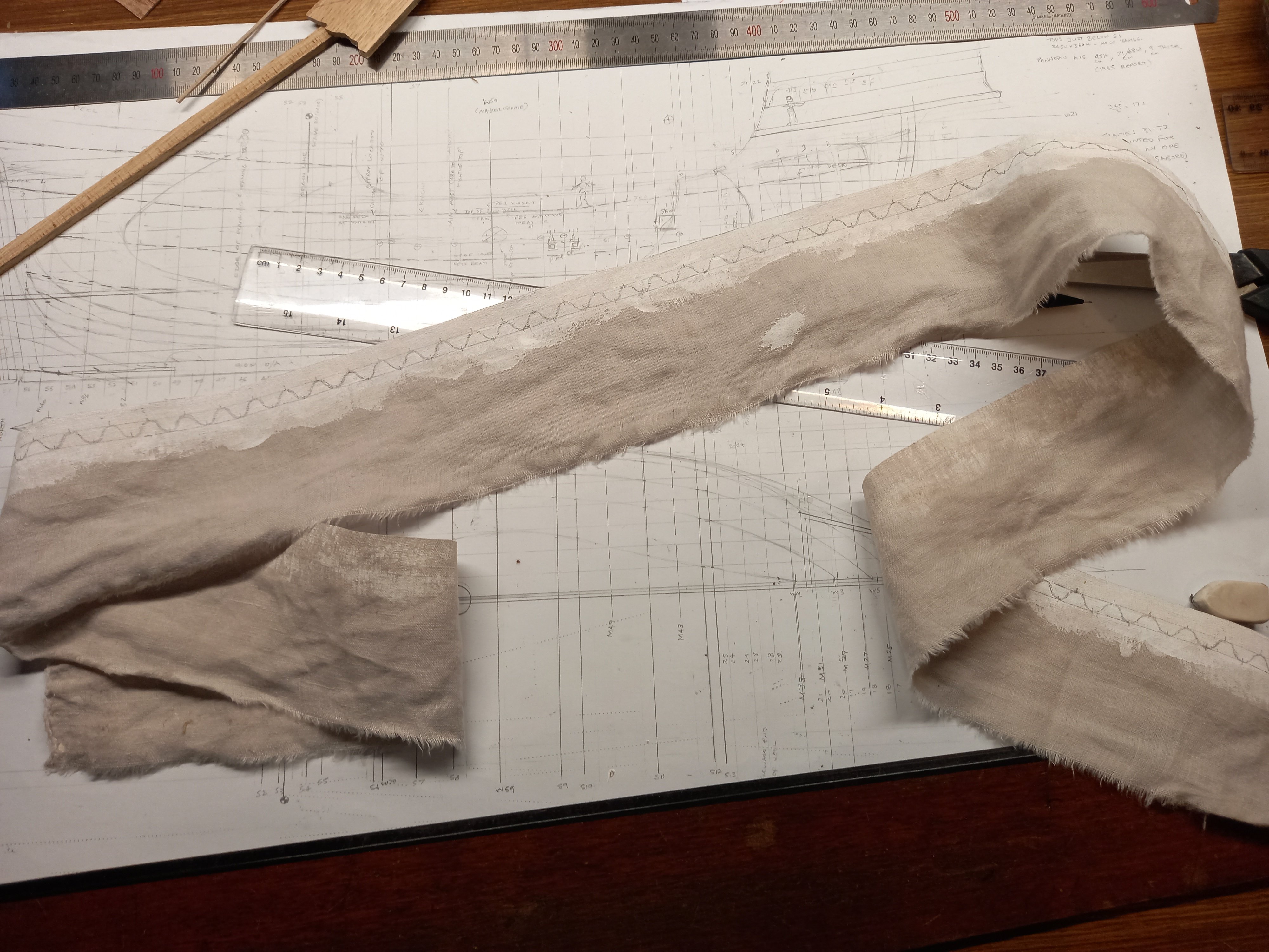
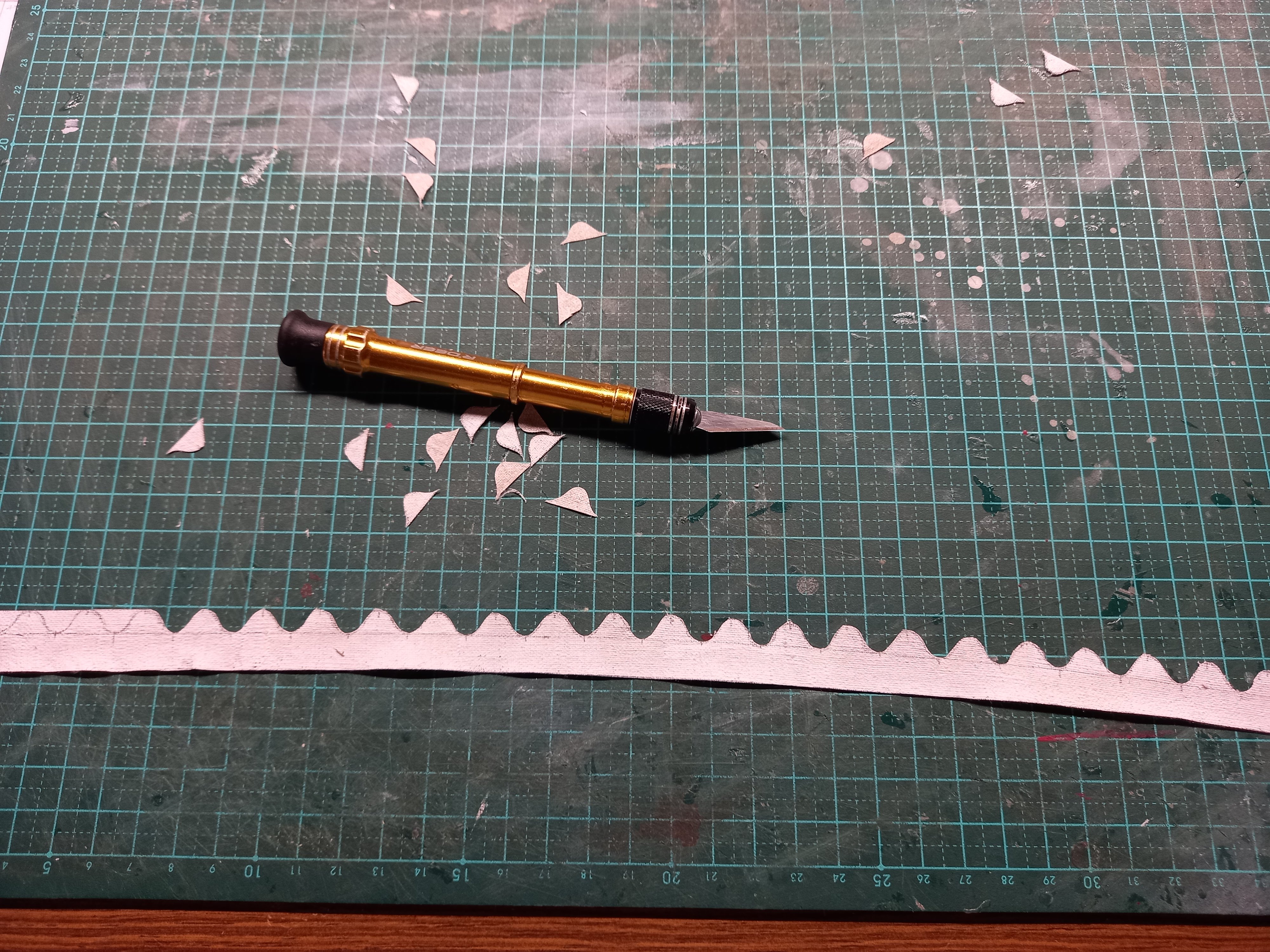
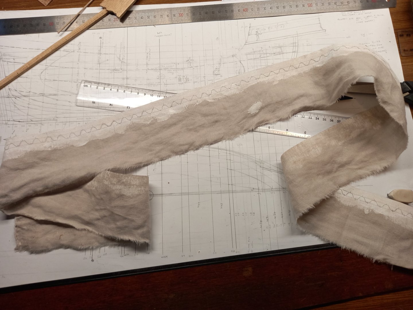
Putting on the safety railing and the mesh below it. I cut the mesh a little wide so it would overlap the upper and lower edges a bit and leave me a little wriggle room - once the upper and lower edges were attached I could trim it to fit exactly. Upper edge panel added aft of the paddlewheels. On the real thing there is a rail behind this panel, made of steel pipe. But I didn't bother to put that on - it would have been invisible anyway. Forward of the wheels doesn't have this panel, just the rail. My trusty plastic mini-pegs put to work again! The panel is made of very thin wooden sheet which bends easily around a relatively tight radius. The sheet wood was only long enough to do one side, so I had to cut two strips and join them at the stern with a vertical mini-scarph joint. And the top rail - made of a thin bamboo rod from a bamboo blind (think of a kitchen bamboo skewer - very similar, but longer), sliced in half so there was a flat face against the mesh. I didn't take photos of the beginning and intermediate steps with this one. And the lower edge added to sandwich the mesh between it and the deck at the bottom. Due to the configuration of the deck, I couldn't use pegs, so I used dressmaking pins instead. Very useful at times, and better than push-pins because they make a much smaller hole. The scarph joint. I didn't want to put pins too near the edges of the bottom strip in case they made it split, so I held the ends down with a bit of masking tape over the top. And once that was added, I put on the paddle wheels. I kept that till very late in the build because they're fragile and I didn't want to break them while I was working on other things. To push the top surface of the wheel assembly up against the bottom of the deck, I slid a couple of bits of wooden sheet in between the wheel and the table, acting as a sort of clamp. That being done, I finally got onto the wavy top border for the awning. I got a bit of old bedsheet (grey unfortunately, I didn't have white) and impregnated it with white acrylic paint, to change the colour but more important to stiffen the fabric so I could cut the wavy border into it later. Then I measured the pattern of the wave and hand-drew it onto the fabric. Very time-consuming. And here it is about half-way through the cutting. Seems to be working ok, but also very time-consuming and rather hard on the fingers. Steven


- 110 replies
-
- 12
-
-
- Paddlewheeler
- Ballarat
- (and 3 more)
-
I soak mine then bend them around the barrel of a cheap electric soldering iron held in a vise. Steven
-
That is amazingly cool. You've really taken the carving thing and run with it! And those spikes are actually quite within the possibilities for a Viking ship. Note the holes on this weather vane, one of quite a number that have been found: They have been variously interpreted as being for pendants, tassels etc but if you look at some Viking cloak-pins that appear to be representations of one of these weather-vanes, whatever is supported by these holes seems to be more like spikes, going out radially: So I think you've got a very good case for your spikes. Nice work, mate. Steven
-
That's not just good carving for a beginner, that's good carving, period. You've done a beautiful job with it. And unlike some dragon-heads I've seen, he really looks like he belongs on a Viking ship. Oh, and the rest of the ship is good, too. 😁 Steven
-
I do have aluminium sheet and I have considered it, but I think it would be harder to work than painted fabric. I'll experiment to see how it all goes. Steven
- 110 replies
-
- 2
-
-
- Paddlewheeler
- Ballarat
- (and 3 more)
-
Looking good, Doug. Generally, the cardboard replica seems to be good. Grytpype-Thynne and Moriarty would be proud of you - for those not acquainted with the original lantern-slide type wireless Goon Show (see 8:50 and onward for the cardboard replica) A couple of observations which you are at liberty to ignore if you wish - it's your model after all. First, perhaps the forecastle is a tiny bit high. Is there a deck on the top of that structure or is that the height of the bulwark/railing, with the deck somewhat lower? If the second, not so much of an issue, but you might still just have a bit of a look at it and see if you're happy with it. Next, are the triangles at the front of the forecastle going to join at the apices (plural of apex) as you have on the cardboard replica? I would have thought there should be a flat plane and/or perhaps a curved surface, across the forecastle at each point, comme ça - That seems to be what is shown in contemporary pics, though admittedly they are a little hard to interpret. I think your placement of the shrouds looks good, and yes, they never recovered the masts, so you can only go with the best available guesswork information. I'd agree the maintop should be somewhat higher than the foretop, in line with the whole mast being bigger and taller. And those guns look very good. Coming along nicely. Steven
-
Thanks everybody for the likes and comments. Firdajan, yes archery was still an important part of the armament of the Mary Rose - in fact I've seen some of the bows in the museum where she's held - along with all kinds of other interesting artefacts including a beautiful parrel truck and a complete fighting top. Back then they were still thinking more in terms of hand-to-hand combat than gunfire, which is why the Mary Rose had such a tall forecastle and aftercastle - to make boarding difficult for the enemy. Tony, thanks. Yes, I'd had no idea that there was this period where they were very wary about installing gunports - I thought artillery went straight from gunwale-mounted to long ranks of gunports. But it's very understandable when you consider the problems that had to be overcome before they could become an integral and usual part of a ship's armament. Mikki, I'm glad you liked it. I do enjoy sharing these discoveries with my fellow enthusiasts. Steven
-
Yes, I'm still trying to work out the best way to do it. Scissors don't come with that profile, unfortunately (though they do for half the scale, so long as it's paper you want to cut). I'm thinking mainly of fabric impregnated with paint, and cutting carefully with a craft knife or similar. Or perhaps silkspan . . . As it's by a lake, I have to think about the effect of moisture. Steven
- 110 replies
-
- 2
-
-
- Paddlewheeler
- Ballarat
- (and 3 more)
-
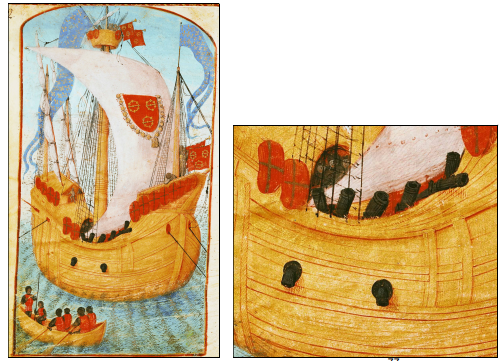
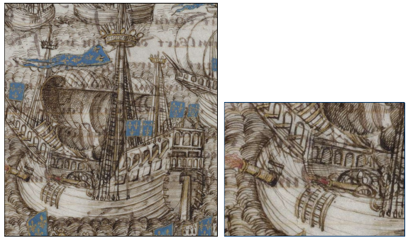
Well, I'm very chuffed. In response to a request from me for a bit more information and a clear photo of an 'arquebus' (precursor of the musket) found on the Lomellina, Max Guérout sent me a thoroughly researched and incredibly comprehensive paper he'd written, covering not only the guns found on the wreck, but every type of gun in common use at the time, with photos, technical drawings, construction analyses, you name it. 108 pages long. But all in French. Fortunately, Google Translate has come a long way since I first started using it, and despite the occasional howler of a translation, that plus my own schoolboy french was very useful in getting the full sense of the paper. Wonderful. One thing I found fascinating was the fact that as gunports had only just come into use -before this all guns were supported on the gunwales (which is why they have that name) - they were so new that the problems hadn't yet been worked out (keeping water out was an issue, muzzles only barely stuck out past the front of the carriage - they were actually within the hull itself when the gun went off - so there was a considerable danger of fire, there were structural issues with putting holes in the side of the ship, as well as supporting the weight of ever bigger and heavier guns). So they weren't very trusting of this new development and initially ships were pierced with very few gunports - possibly only one or two per side, as in the pictures below, with other guns (even big ones) being still on the upper deck and fired over the gunwale. The French ship Loyse (Louise) - c. 1486-1508 From the manuscript of Rochechouart c. 1502. Among the finds on the Lomellina were a number of large wheels, much larger than those of the usual carriage found on shipboard guns of this time (though note the Mary Rose had them too) - about the size you'd expect for field guns. Except that some of these didn't have iron tyres, or even the rusted remnants of them (which are usually very obvious because they make a huge swollen mass). No good for wheels that had to stand up to travelling along the dreadful roads of the time (or, worse still, off-road). Which indicates they were intended to be used, not on land, but on board ship, as shown in the picture. There's a good chance that despite a dozen gun barrels having been found in the wreck, the gunport and portlid found on the Lomellina were the only ones on that side of the ship, and the other guns were on the upper deck. Loving this. Steven
-
That's the problem with the breech-box method. And pretty hard on the gun itself having all those combustion gases escaping between the barrel and the breech-box. That video was fantastic to watch. I've put it in my favourites. Steven
-
But when you come to Ballarat, be sure to let me know you're coming and I'll show you around. Steven
- 110 replies
-
- 2
-
-
- Paddlewheeler
- Ballarat
- (and 3 more)
-
Nice work, Mikki. Coming along well. Steven