HOLIDAY DONATION DRIVE - SUPPORT MSW - DO YOUR PART TO KEEP THIS GREAT FORUM GOING! (89 donations so far out of 49,000 members - C'mon guys!)
×


Louie da fly
-
Posts
7,989 -
Joined
-
Last visited
Content Type
Profiles
Forums
Gallery
Events
Everything posted by Louie da fly
-
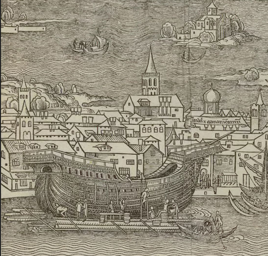
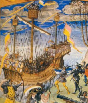
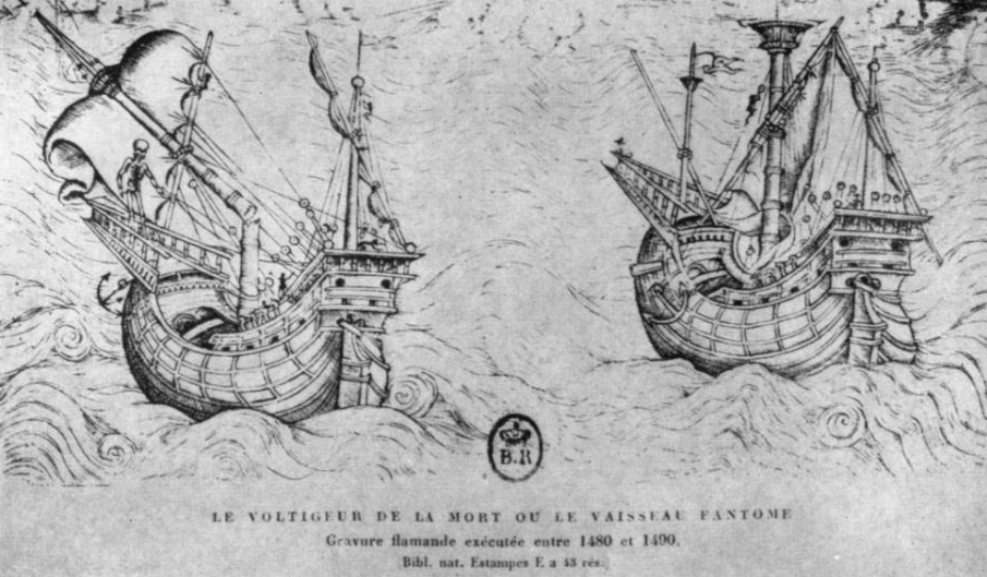
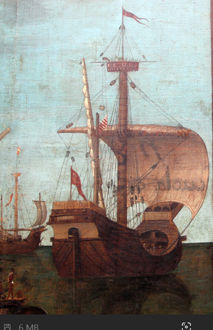
 Yes, wonderful artist though Botticelli was, I'm not sure he was au fait with the intricacies of ship design. I know of only one other painting of his that incorporates a ship, and it's identical to this one - obviously working off the same sketch. I'm not so sure about the crosswise planking on the poop. It is within the bounds of possibility that this is correct. The poop is a separate structure from the rest of the hull. Though it does seem to make sense that the deck beams would go from side to side, in fact if they went fore and aft they would be spanning a smaller distance and so they could be made of lighter timber. The only heavy timber needed then would be the one that supported their ends, at the break of the poop. Agreed. It's very difficult to interpret. I'll be looking at other pictures of carracks and see if I can make sense of it. If not, I'll go with what the majority show. It's a judgment call, I'm afraid, as are so many other things in this build. Here's a picture that might explain the configuration. The rail seems to be almost continuous but not quite, and there are definite breaks at the quarter deck and the poop. And another where the railing is definitely continuous, but perhaps there's no poop. I think there was a fair bit of variation in the configurations in use. Still thinking about it all. Steven
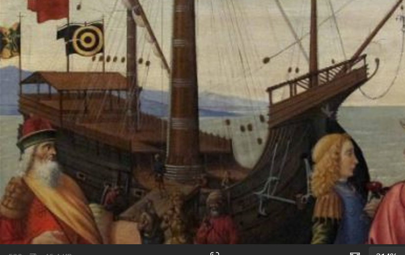
-
I've been thinking about whether or not the ship should have a poop deck. Botticelli's Judgment of Paris is one of the very few images that show a carrack from a viewpoint that shows the decks, and he shows one. It's also a good guide to where the hatches are and various other interesting details. But I think he's made a mistake with the location of the ladder to the poop - it seems to be in a completely illogical place - with the bottom at an open hatch and the top at a set of crossbeams you'd have to clamber over to get to the poop. Perhaps he did his sketch a bit wrong? He's not noted for his maritime pictures and may not have thought through what he was painting. It's hard to make out if there's a separate quarterdeck or the "main" deck continues all the way from the forecastle to the poop deck. Those railings to the main deck are unusual, as well, apparently continuing the same line as the railing at the poop. Needs some thought. Steven
-
Hi Vivian, I just saw your reaction to my Winchelsea nef. Nice to see you back on the forum! Steven
-
Oh, yes! I'm duplicating the frame spacing on the original. The distance between centres is about 500mm (a bit over 1 ft 6 in). The planking is actually fairly thin in the grand scheme of things. Ten to 12 cm ( 3 to 5 inches) except on the upper works, where they are about 4 cm (about one and a half inches) thick. That translates at 1:100 scale as 1.0 to 1.2 mm (1/25 to 1/20 inch) and 0.4mm (1/60 inch). Steven
-
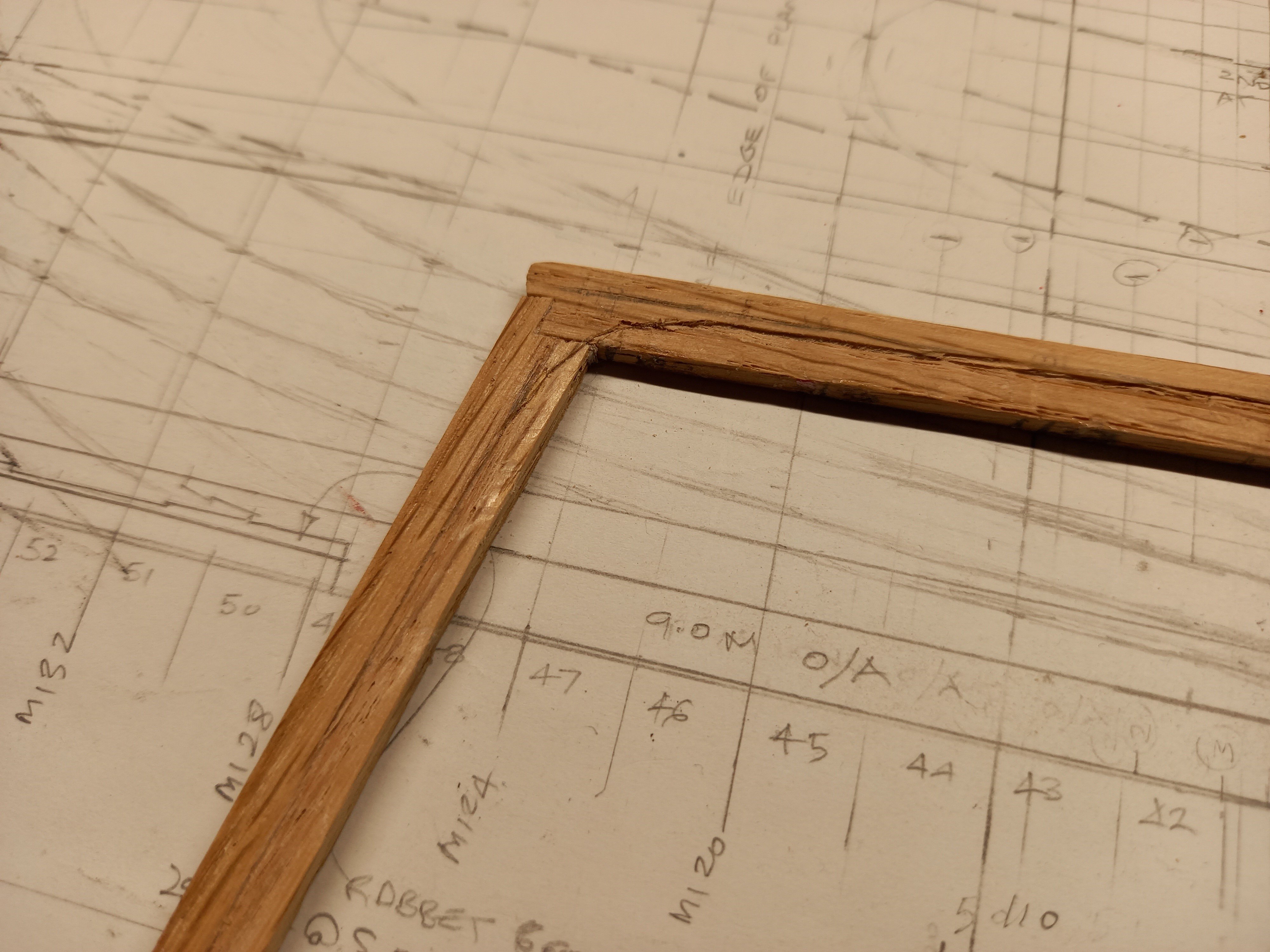
More on the Lomellina - The rabbet carved into the keel, curved at the corner where the keel joins the sternpost. Oak really isn't a terribly suitable wood for this work. And the keel with rudder and four frames. Only 84 frames to go! Because of a design conflict between the archaeological finds and the recent theoretical reconstruction, I'd thought I needed to move the lower deck downwards , but as it turned out I had the height correct in relation to the frames. But I did have to adjust the deck heights on the sheer plan, and consequently the heights of the gunport and the pump lands, the gunwale etc. All good. Steven


-
Latest update - Sutton Hoo Ships Company January Newsletter - https://mailchi.mp/saxonship/the-sutton-hoo-ships-company-17986272?fbclid=IwY2xjawIKOzhleHRuA2FlbQIxMAABHWz-OYAyJMsA7OzXjhr-CdILiPbR8rD7INDiQXeIdwaQ5P14Vd_O7y7Ybw_aem_p0ziokhDskwNc-IYwqiPow Steven
-
Very true, very true. I've often come across this in my own research, not only relating to ships. I remember a 'fact' bandied about among Anglo-Saxon re-enactors (when I was doing re-enacting) , that King Knut had decreed that all his housecarls (bodyguard) were required to have gold-hilted swords, and another that Anglo-Saxon women liked the Vikings better than their own men because they washed more often and looked after their personal grooming. I tracked these statements down and ended up finding that the source in both cases was something like 200 years after the events were supposed to have happened. Hardly eye-witness accounts. Plenty of other examples. And yes, we also have to take into account the politics involved. People alter the facts to suit their own narrative or push a political agenda. Yes, it happened back then, too. It requires great care not to be led astray, and even then we must usually hedge our conclusions around with so many qualifications that sometimes we feel that we are certain of nothing. In the long run, it's largely educated guesswork, based upon nebulous factoids that may or may not be reliable. But in the long run we have to decide something and go with that. Steven
-
Great opera. Lots of fun. I played violin in a youth orchestra for some years when I was a nipper. Too many years ago to be comfortable 😁 Steven
-
You've done a very nice job, and I'm sure you're right about the decoration on Spanish ships - perhaps it might have been even more ornate than the others! Steven
-
The heat sink would also keep the peg from getting glued to the piece you're working on. Steven
-
Nice. Better than carving by hand (which is how I've been doing it). Steven
-
I know this is a bit off-topic, but I'm curious. When you say you've "played it", you mean played an instrument in an orchestra for the opera? Steven
-
I always felt that way about Italian. Look at the way "non piu andrai" from Mozart's Marriage of Figaro is sung . . . sounds like 'non pyandrai' https://www.youtube.com/watch?v=e1-FKyOTvto And just relax and enjoy the music. Love it. Steven
-
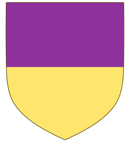
Nice one. You might also consider an additional banner - a long triangular pendant being a simplified version with the three main "field" colours of the coat of arms; white, green and gold/yellow - so perhaps green and gold together as two halves of a square by the flagpole, and a long white triangle as the 'fly'. That seems to have been a 'thing' with these flags. Steven
-
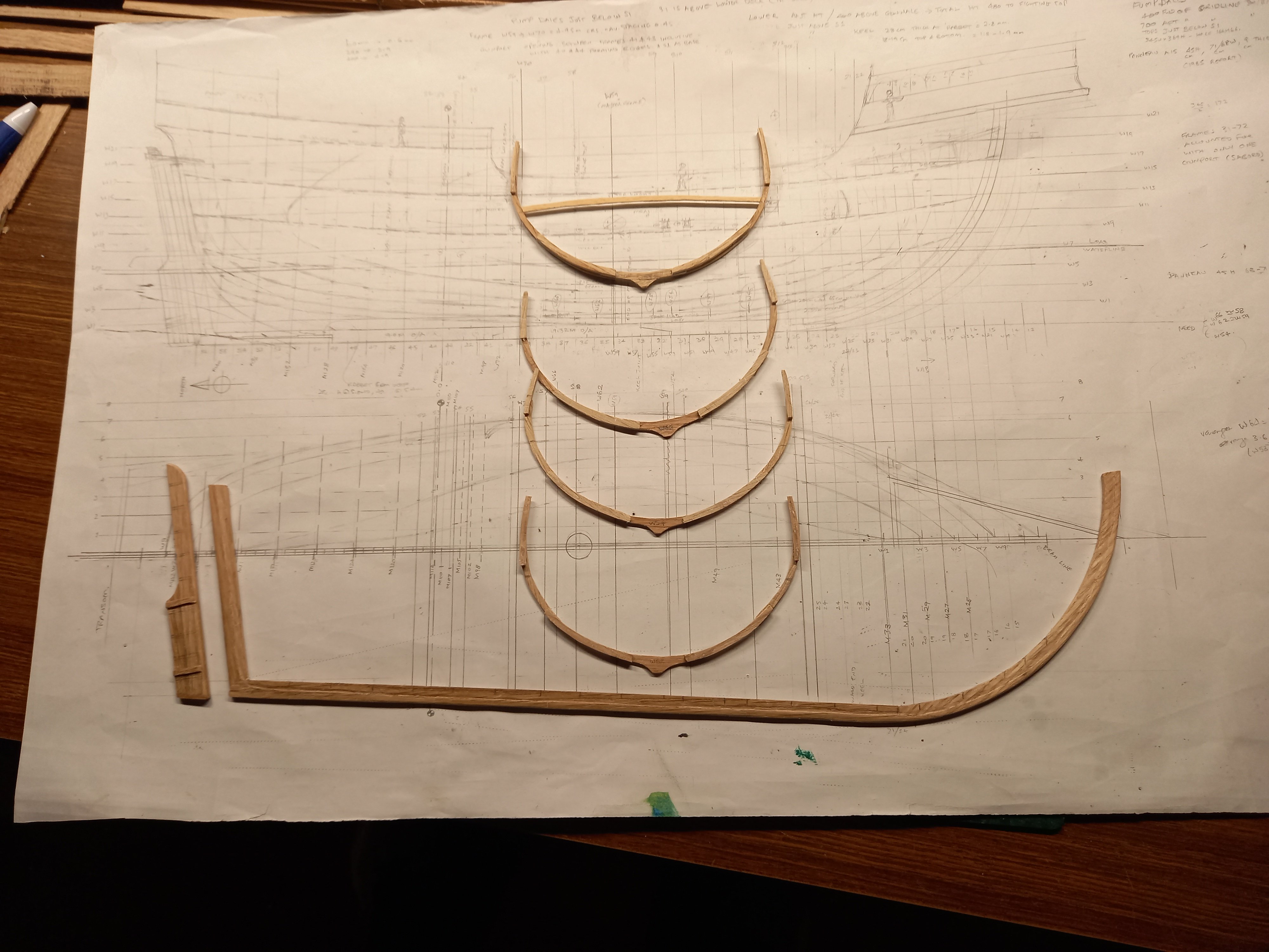
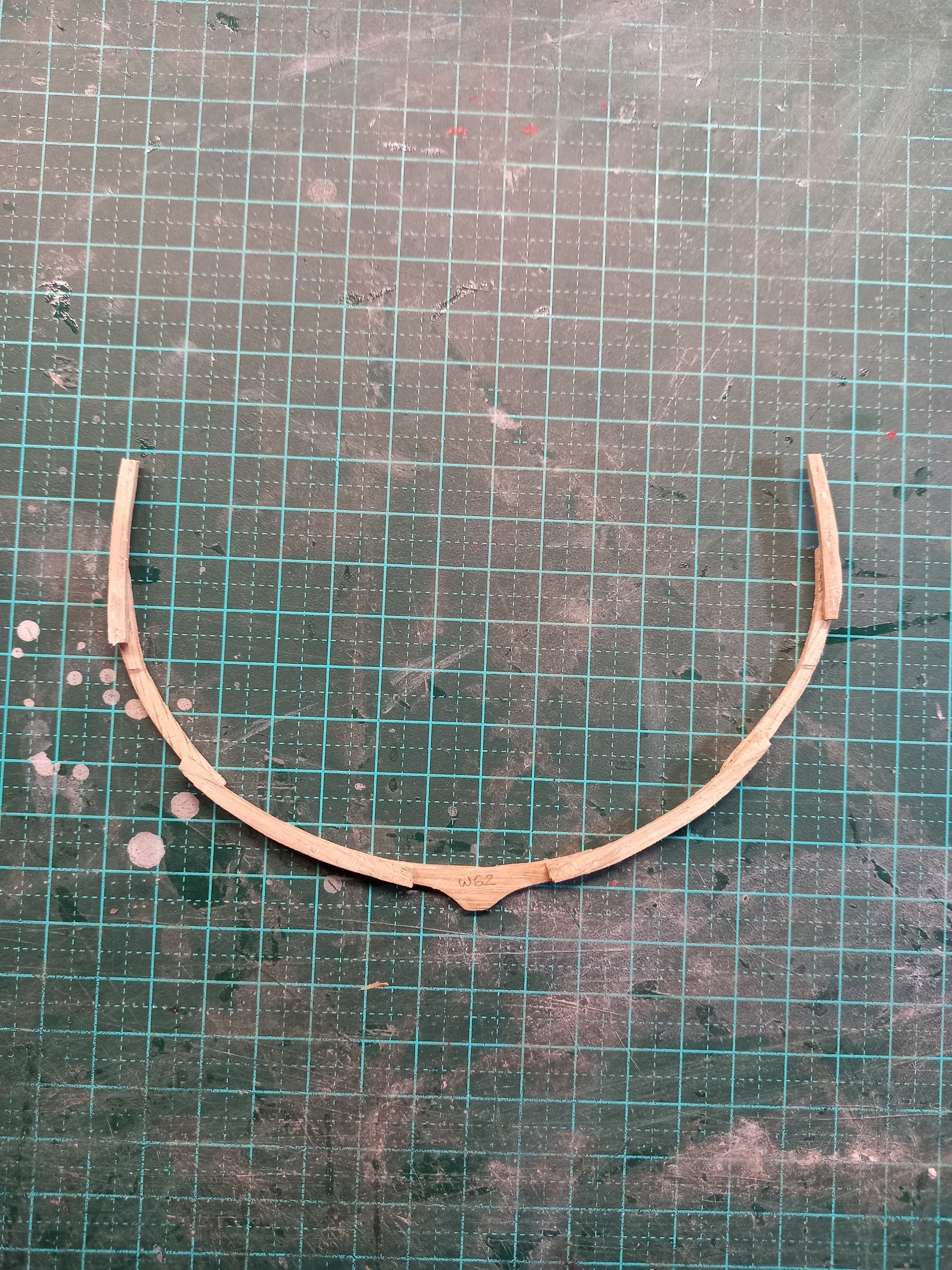
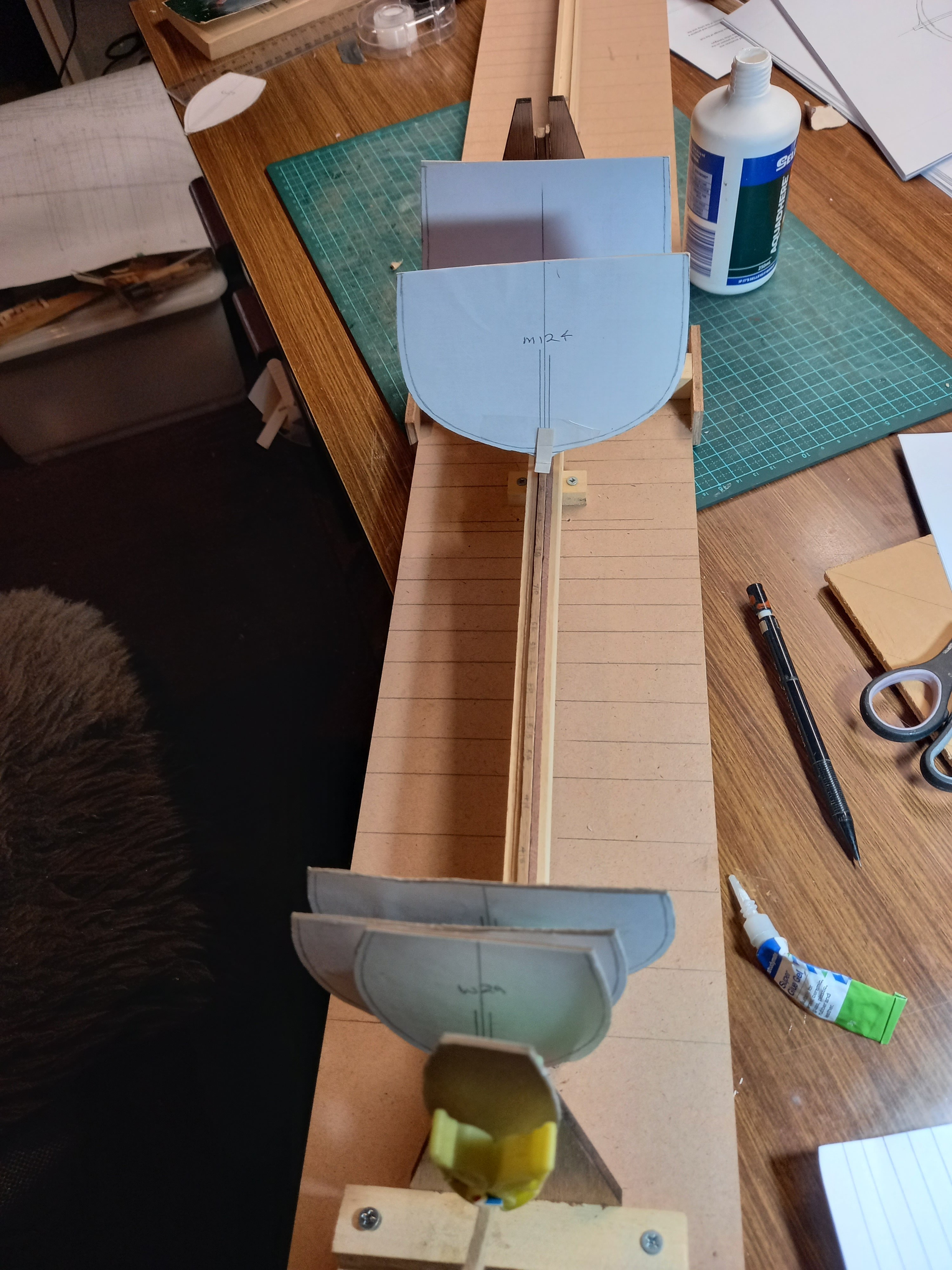
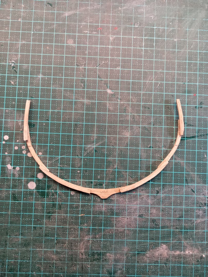
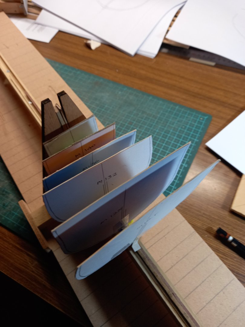
Made another frame. They don't take as long to do as I'd feared. I've been concerned about the shapes of the frames at the bow and stern. Because the model is based on a wreck which is very far from complete I'd had to generate its lines from the remnants and from the lines of other ships of the same general time-frame (notably the Mary Rose, God bless 'er), and then use those lines to work out the shapes of the frames, and all this the first time I'd ever tried it, there was a fair bit of uncertainty. What if I've got the shapes wrong? Do all that work making them, waste all that wood - only to find they're wrong? So I cut out their shapes from card and put them (very!) roughly in place on the keel. They seem to work, so I feel better about going ahead with them when the time comes. Steven

-
I went a different way, following up directly via Portuguese heraldry. This seems to have had results. First look at this one - https://en.wikipedia.org/wiki/Portuguese_heraldry That gives a good overview. And mentions that King Manuel I (1495-1521) forbade the use of arms to those who were not of the Portuguese nobility. So if you want a coat of arms and therefore a flag based upon it, you need to be a noble - but I think the noble class would also have been the major shipowners anyway (as I understand it Portugal was very hierarchical). That article provides a link to this: https://en.wikipedia.org/wiki/Livro_do_Armeiro-Mor which contains a section "Princes and Main Houses of Portugal" showing the arms of several noble families, plus a bit of their history and achievements from which you might like to pick one. It even has the arms of Vasco da Gama - hey, why not have the ship belong to him? Certainly a maritime connection there! Steven
-
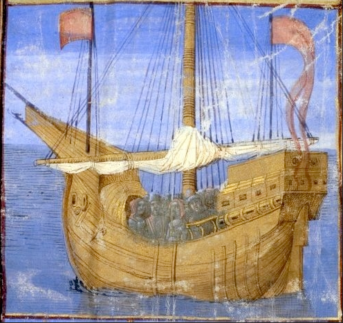
I'd agree that it would be the owner's flag. If the person was important enough (and presumably a shipowner would be well enough off to be regarded as important) he may well have a coat of arms, and that would be shown on his flag(s). For example, the image of what I believe to be the (first) Lomellina shows the flag of the owners, the Lomellini family, which is an adaptation of their coat of arms. Do you have any particular owner in mind? I'm assuming the ship is Spanish? If so, perhaps look at a few contemporary Spanish merchants'/shipowners' coats of arms. For example https://www.istockphoto.com/vector/heraldry-coats-of-arms-of-spain-gm928877224-254747533 shows a number of non-royal and non-regional coats of arms from Spain (and links to others). I'm assuming the names under the shields are family names, but I'm not sure. Perhaps choose one you like the look of that isn't too difficult to reproduce and use that. If you really want to do it properly, perhaps research the family name and see what they were into and if they lived on the coast? A couple of things - what's the purpose of the weight? I don't see what it's there for. And I'd recommend a multi-tine spear - that seems to have been the thing for fishing - presumably because a fish could wriggle off a single point. Sorry, I realise that means more work for you . . . Steven
-
Yes indeed. Though it's going to be a slow process, I'm afraid. 88 frames to build up out of bits. But I'm not in any hurry. The plan is to make every fourth frame and place them on the keel, then fill in the gaps. I have the positions of the 'one in four' frames marked on the keel in pencil. After a bit of recherche research (sorry, I've just been speaking French for an hour and a half) I think the consensus of the (relatively) reliable pictures is that yes, though the planking curves up at the stern and some of it ends under the counter, much of it it nonetheless butts into the sternpost so it needs a rabbet. Ah well, better to find it out now before I commit myself by gluing any frames to the keel. The sequence of actions is important - I need to make sure I don't paint myself into a corner (in French 'me coincer' - I just learned that one today.) Steven
-
Seriously impressive work, mate! Wonderful to see you're using Anderson as your guide. Extrapolating backwards to allow for the difference in eras can be a problem, but it's really the only option available. Within reason I think we can assume that the earlier we go the simpler rigging becomes. But that's not a hard and fast rule - look at all the crows-feet they used in the 17th century and dropped later as being too unwieldy. You just have to go with what seems to you to be most likely. And nobody without a time machine is going to be able to tell you you're wrong. Steven
-
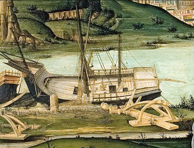
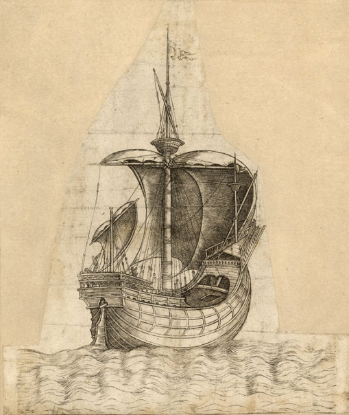
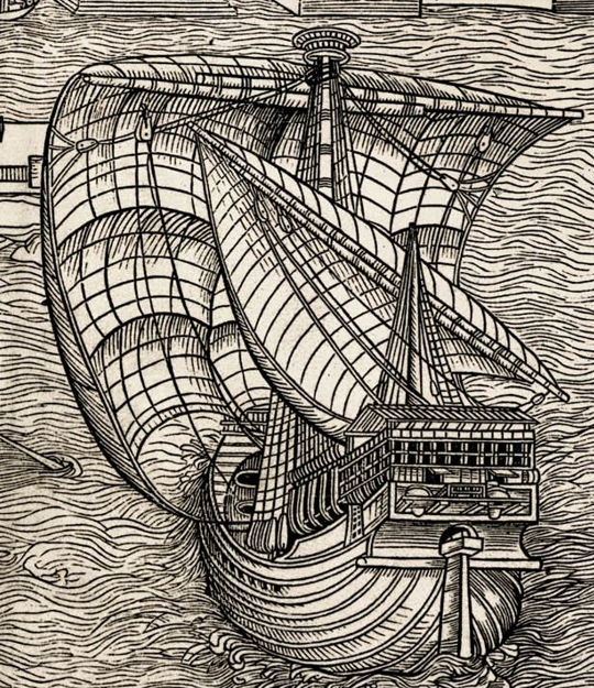
Tell me about it. It's interesting using the stuff, but I'm not planning to repeat the experiment (and the experience! ) in any subsequent models . . . Mark, thanks for that. I'm still in two minds as to whether to extend the rabbet into the sternpost. Baker sent me some very good stuff from the Mary Rose which I've taken on board, but unfortunately she had a square stern, not a rounded one like earlier carracks, as mine is. OTOH, looking at Carpaccio's superb contemporary renditions of carracks of the time, he seems to show the planking curving upwards, not sideways. However, even Carpaccio seems to have made the occasional error (perish the thought! Say it's not so!). So I'm still considering my options. I'll go through my collection of contemporary images and see if I can work out what's the best way to go. Regarding the roundness or otherwise of the fore edge of the rudder, Baker's info has enabled me to solve it - yes, the Mary Rose had a rounded edge to the rudder. That's good enough for me (and it seems intuitive anyway). Steven PS: Forgot to thank everyone for the likes to the last main post. So thanks, people!
-
Getting close now. Regarding the fishing gear I can't comment on this period with any certainty, but apart from nets (with floats and weights attached, perhaps - depends on the technique they're using - just tossing the net over the side and drawing it back in? Or something a little more sophisticated?) the only other thing I've come across was Byzantine 11th century, a multi-tined 'fork' (it would be a trident if it had only three but there were more). The Serçe Limani "glass wreck" had the following: "The fishing gear found in the Serçe Limani shipwreck in Turkey included nets, spears, sinkers, and spindle-whorls. The shipwreck dates back to the 11th century AD. Fishing gear Nets: Three large nets with floats, a smaller casting net, and beach and open-sea seines Spears: A multi-tined spear Sinkers: Fishing-gear sinkers, some with Christian symbols Spindle-whorls: For making lines Netting tools: Tools for working with nets I tried to find images but couldn't lay hands on them. The article linked below Aha! 7th century AD, but some very nice pictures: https://www.ancientportsantiques.com/wp-content/uploads/Documents/PLACES/Levant/Dor-Galili2010.pdf I don't know if the fishing method would be the same, but it's probably quite likely. Oh, and a set of balances to weigh the fish with. The linked article has pics of (modern - but almost identical to ones found in archaeology) balances to weigh the fish, a fishing spear (and a mosaic of one in use) plus a mosaic of a net being used. It also mentions finds of fish hooks, and pictorial representations of hooks "with and without rods" Have fun with it. Steven
-
Patrick, I've had a look at those pics (didn't realise at the time what ship they came from). I think it answers my questions. Many thanks. Steven
-
I've been away for awhile, so please forgive the longwinded reply - a lot to reply to all in one go, with the fast progress you've been having. Regarding your post #33 of Jan 15 I'm going to (reluctantly) take the role of advocatus diaboli. While I agree that it's quite possible contemporary pics don't show 'permanent" gaskets, it's difficult to draw definite conclusions - the gaskets may be temporary, but maybe the artist just didn't bother to show them. To be able to see the (unused) gaskets hanging down from the yard, firstly it would require a picture of a ship with the sail(s) set. Second you need a very good artist to notice and include such a fiddly detail. And I'm afraid even my favourite, Carpaccio, sometimes gets details wrong. Even he might have missed that detail, particularly of a ship under sail if observing from the shore. Not saying you're wrong. It's quite possible you're correct, just that the evidence is a bit equivocal. But that's not what is shown in the pictures in your post. In each case the yard is considerably above deck level with the gaskets being tied or already tied. OK, enough devil's advocate. On to the rest of the post. Actually, credit for this diagram should go to Woodrat, who generously shared it with me. See the motto in my signature . . . 😁 That's a nice fix for a problem forced onto you by the kit manufacturer, who probably never imagined that anyone would attempt this level of detail and accuracy on their model, and certainly wouldn't have thought through the consequences for sail control caused by the mast placement. You're doing a very good job of this whole build - very workmanlike, and based on thorough research and practical thought. And high quality modelling. Well above the quality you were presented with by the kit. Something to be justly proud of. Steven
-
Yep. It gets into the brain, doesn't it. And you're never the same again . . . Steven