Keith_W
-
Posts
1,145 -
Joined
-
Last visited
Content Type
Profiles
Forums
Gallery
Events
Everything posted by Keith_W
-
 Those non-flush reinforcements are found in parts of the frame that should be tapered for planking. I wouldn't worry about it. And please yes, make her swim.
- 414 replies
-
- 2
-

-
- riva aquarama
- amati
- (and 2 more)
-
Hello Aydin, I will be following your build log as well. I for one would love you to build it for full RC operation, swimming and all. There are a number of concerns that I would have if I was building this kit - 1) how to make it watertight, 2) how to balance it in water, and 3) how to apply a perfect gloss coat, and 4) how to avoid parts from falling off when she goes swimming. I would be very interested to see how you overcome these.
- 414 replies
-
- 2
-
-
- riva aquarama
- amati
- (and 2 more)
-
All of us on this forum make models. But our models do not tell a story, yours does. This is why this is art, and what the rest of us are doing are mere ... models. Very clever idea Igorsky! I have loved all your previous scratch builds, but a diorama ... in a bottle ... of one of my favourite Hemingway novels surely is the icing on the cake. This is imagination on something which is different to what most of us attempt, and I love it.
- 131 replies
-
- 4
-
-
- bottle
- the old man and the sea
- (and 1 more)
-
Wow, sharp eyes. Another tool to add to my "must acquire" list.
- 593 replies
-
- 1
-
-
- royal william
- euromodels
- (and 1 more)
-
Thanks Brian. Don't know if you missed the post somewhere above, but I did remove a section of the masking tape to see if there were any problems. It came off easily and with no residue, so I reapplied it. Seems as if good old Tamiya is quite safe to use! Of course, the real test will be at next month's model expo, where I will be removing ALL the masking tape for the display. The good thing is, there will be no fragile features installed by then, so if I need to I can sand the hull back down and repaint if necessary ... but I think I probably won't have to do anything like that. Fingers crossed.
-
Not planning to paint the lower hull white, Mark? BTW if you send a PM to rshousha, he has some RW hinges. I have some. I think that Brian the Extraordinare also has some. I don't think he is planning to use his, so you may be able to get it from him.
- 652 replies
-
- 2
-
-
- royal william
- euromodel
- (and 1 more)
-
Hi Vince, I am working on the same area of the ship as you at the moment. I thought I would drop in a note to remind you to drill holes for your gammoning. I note that you have installed the lower set of decorations minus the gammoning hole. There should also be another gammon hole just inside the railings. This will be almost impossible for you to install if you do the beakhead railings first. Sorry if you were already planning to do this, but I thought that I should give you a reminder in case you didn't realize this. (edit) oops, just saw the gammoning hole!
- 593 replies
-
- 1
-
-
- royal william
- euromodels
- (and 1 more)
-
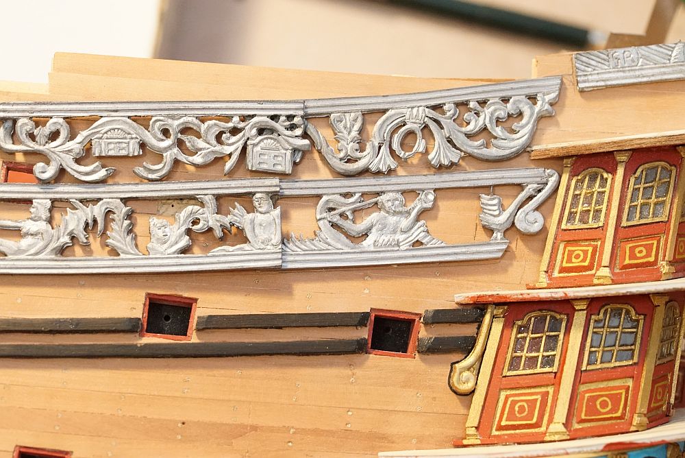
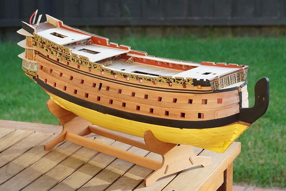
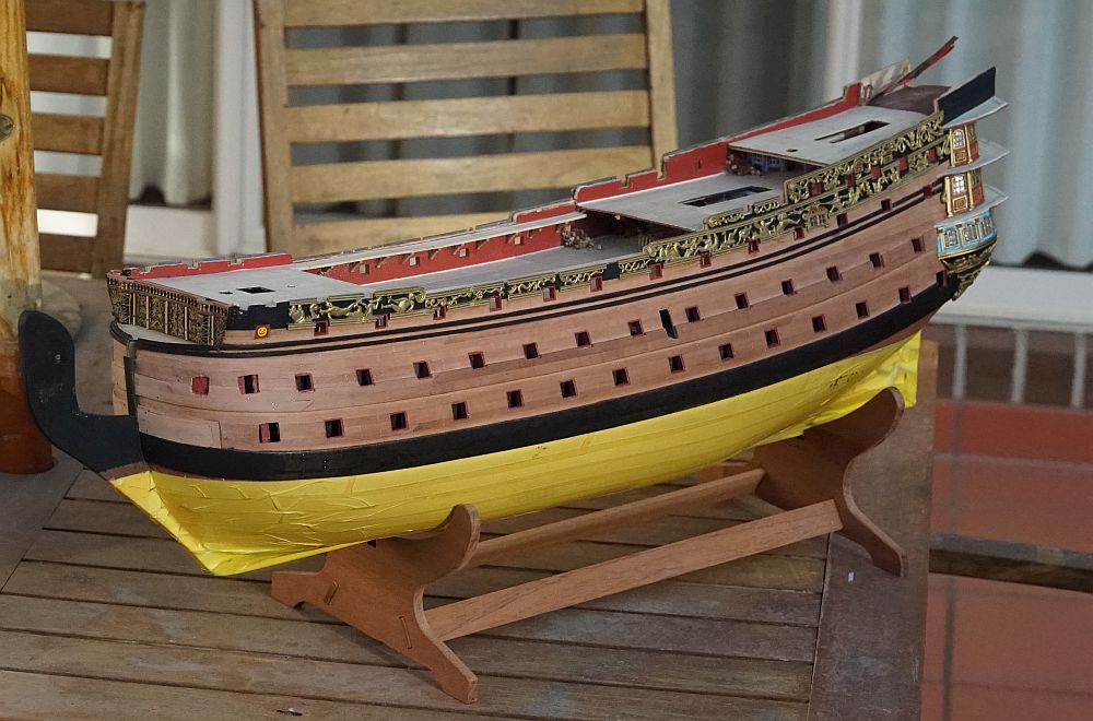
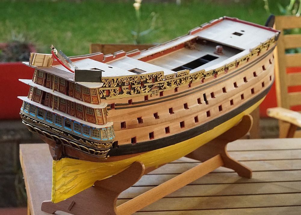
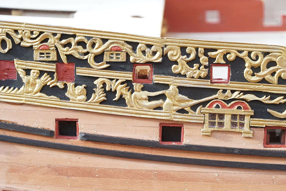
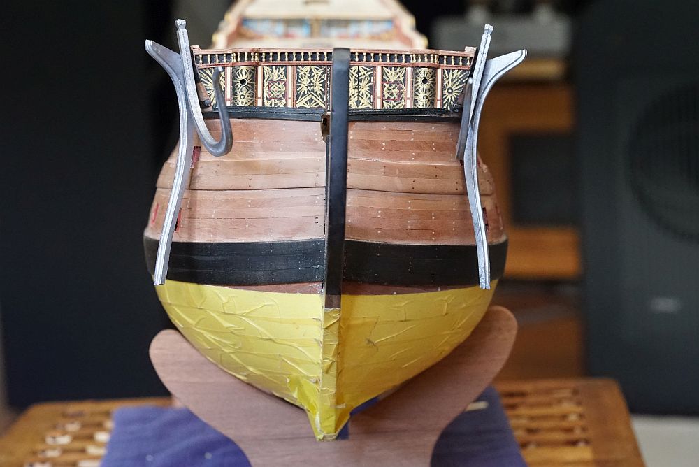
Here are a few vanity shots ... just for fun. Taken in the backyard on an Australian winter morning. Yes, the sun is out. Grass is green, and the sky is blue. But it is really cold!! The other side. Decorations have been placed all the way to the front with the exception of the last piece. Once the beakhead railings go on, the last piece will be placed. The position of all the gunport holes have been finalized and cut out. Note also the gaps in the decorations that I left for the fenders. I have not shown a picture of the fenders yet, but they have been cut, sanded, and ready to be installed. Because the top of the fenders need to reach the cap railings, the top of the fenders have not been trimmed. I do not want to leave the tops sticking out while I work on the rest of the ship, so I will leave off installing the fenders until I am ready to install the cap railings - which will come after the transom is completed. You can also see that the pear planking in the front is a lighter shade than the rest of the ship. This is because it has been freshly sanded in preparation for the beakhead railings to go on. The darker shade of pear is what pear looks like when it has not been sealed and has been absorbing oil from my fingers for more than a year. From the back. You will note that the top of the decorations look a little irregular. Can't be helped, that is the nature of what was supplied in the kit. Once the wooden caps go on, everything will be sanded until it is flat. The completed repair of the re-positioned gunport I showed in my previous post. I saved all the offcuts from the decorations in case I might need them. In this case, I lengthened the decoration by gluing in parts that I had to remove from other pieces to accomodate gunports and so on. Close up of the three windows which I replaced. In hindsight I could have left on Euromodel's supplied smaller windows instead of removing them - they are barely noticeable when the model is viewed in full. And my replacement doesn't look that great. You can also see that I have filled in the gaps between the decorations with some epoxy putty and painted it over. Keith Julier says that the joints are almost invisible once you do this. Well, i'm no Keith Julier so my joints are still visible! I will probably go and sand them back a bit more to see if I can improve on this.
-
Thank you for your contribution, Pete. I don't mind people commenting in this thread - one reason I post this log is to show others what problems I have had and what I had to do to overcome them. Since I started this build, I have perhaps had to move the position of 10 gunports. It is not the vertical position that is the issue - that is easily determined by the gun blocks, or by trial fitting an assembled gun carriage. I determined the height of the gunport by poking pins through the hull until it went directly into the barrel of the gun carriage, or onto a mark that I placed on the gun blocks (for the lower deck guns). The issue is the horizontal position. The position of most of these ports do not matter, except for the ones I have pointed out.
-
Thanks for all your likes and comments guys! It is very much appreciated. Not as great as PiratePete's Interpretive Info. Any prospective modeller who wants to attempt this kit is well advised to take a look there. I have read and re-read it so many times that I have almost committed it to memory. Still - this is a very large and complex kit - there is plenty of info which Pete has not included. I am hoping that if you take the sum of all our build logs and Pete's I-I it will make things much easier for others. I am very open about posting my mistakes and what I have to do to correct them. If I were to re-attempt this kit, I would do a much better job of it. Hopefully, someone else who comes along will not repeat the errors that I made, and I have made plenty.
-
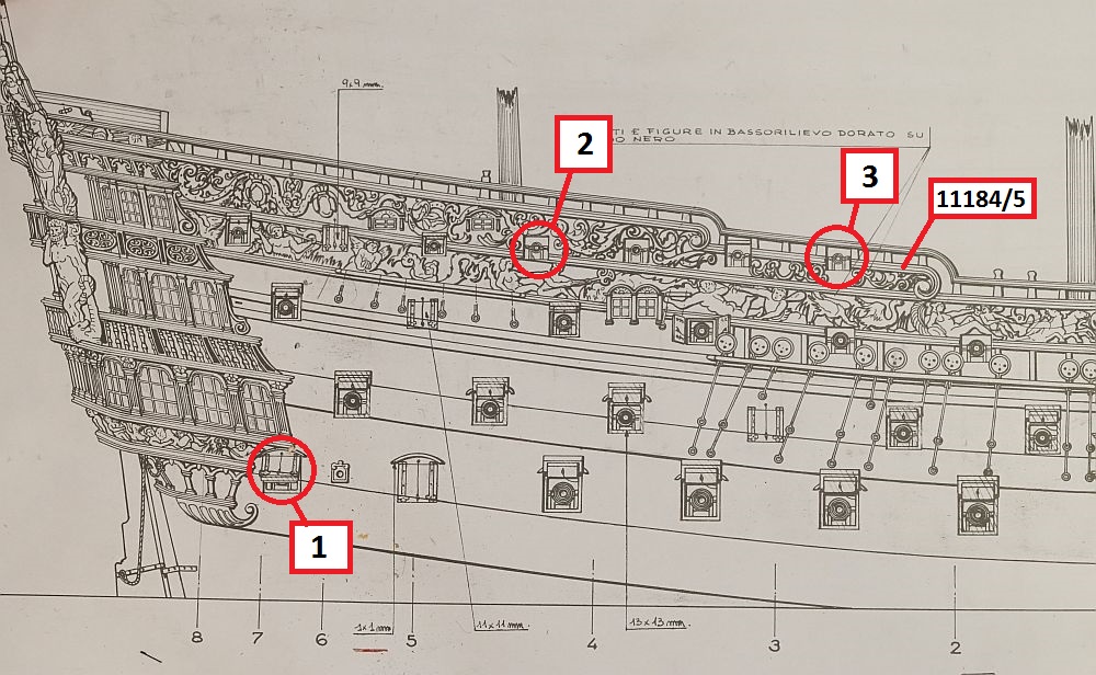
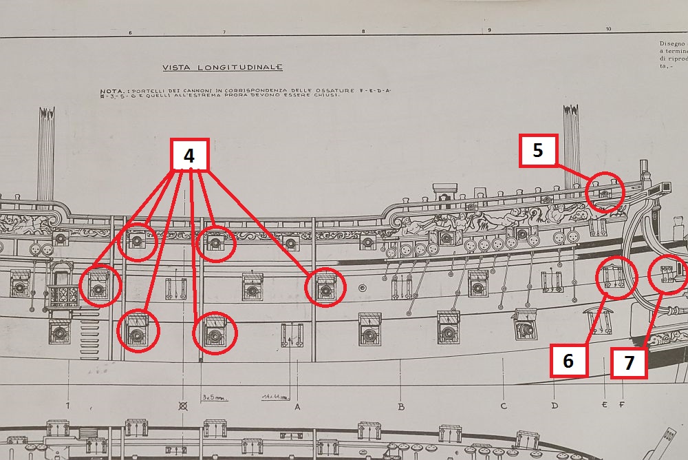
For those who have yet to cut out the gunports, you should take note that the position of some of these gunports is absolutely critical. Not all are. Ideally, Euromodel should provide pre-cut plywood gunports, like other kit manufacturers. If they don't, they could supply a paper template - but they don't do that either. Instead, they supply plans. Whilst the plans are very good, they are a 2 dimensional representation of a 3 dimensional shape. As a result, the position of any features drawn in the plans which curves away from flat in the real ship can not be trusted. Furthermore, what most RW builders have done is trace out the plans on tracing paper, then align the tracing paper on the model to cut out the gunports. This is not reliable either. I have multiple gunports which are off by as much as 10mm - in 1/72 scale terms, this is a massive error. Fortunately, the position of most of these gunports don't matter very much. But a few of these gunports definitely matter, and I would like to draw your attention to them. 1. The position of this gunport should be located at the end of the transom support (Parts 54/55). It abuts, but does not cross Frame 7. Because this gunport does not open, I would suggest that this gunport not be cut out until the transom support is located. Otherwise your transom support might foul the gunport opening. This is not a discovery you want to make when your second planking and wales have already been installed. Fortunately, mine were correctly cut out. 2. This gunport is located immediately under the termination of the poop deck. As other posts have indicated, the length of the Euromodel supplied poop deck is incorrect when compared to the plans. Most of us have shortened the poop deck. If you do this, you will now find that the gun carriage which should be installed in this position will foul the curved staircase that should be installed. If you have an eye for this kind of detail, I invite you to look at all the pictures of Euromodel RW that you can find. You will see that this is a common mistake - a mistake that I also made. I had to fix my error by re-locating the gunport (install wood blocks, re-cut). Don't do what I did - learn from my mistake! 3. The position of this gunport on the second quarter deck should be exactly one length of metal part 11184/11185. You will see from my above post that I did not realize this. Fortuitiously, on one side of the ship the position of the gunport was exactly correct. On the other side, I was off by 5mm and had to make repairs. 4. If you locate these gunports improperly, you will not be able to install the fenders. I realized this before the second planking went on, and I had to relocate a number of gunports to accomodate the fenders. The fenders are 3mm wide. I suggest you cut a strip of 3mm wood and check that the position of your intended gunport does not foul the fender before you cut it out. Take reference from the location of the side entrance. It should abut (but not cross) Frame 1. 5. If you do not take care in the location of this gunport, you will foul the cathead. Do not cut out this gunport until the location of the cathead has been determined. 6 and 7. Neither of these gunports have their position accurately marked in the plans. This part of the ship curves away thus the position can not be trusted. You will note that neither of these gunports can be opened, and the position is strongly influenced by the position of the beakhead railings. I suggest you do not cut out these gunports until you have dry fitted the beakhead railings. With the rest of the gunports, you can have an error of a few mm and up to 1cm but it won't prevent you from installing any features. These are the only gunports you need to worry about.
-
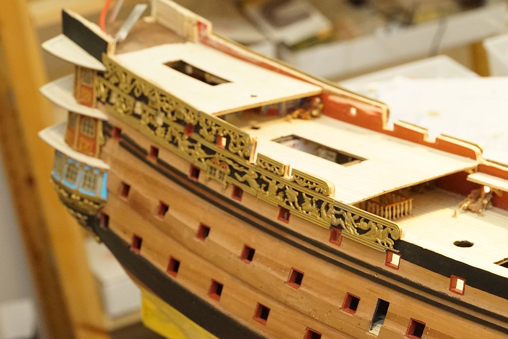
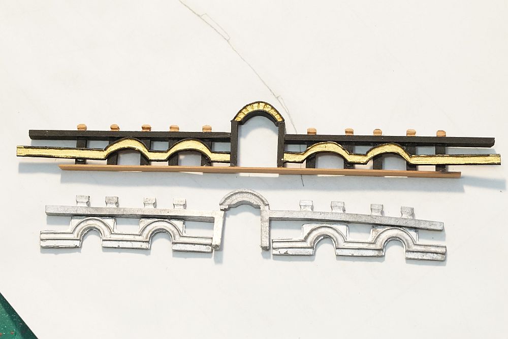
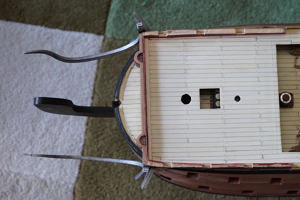
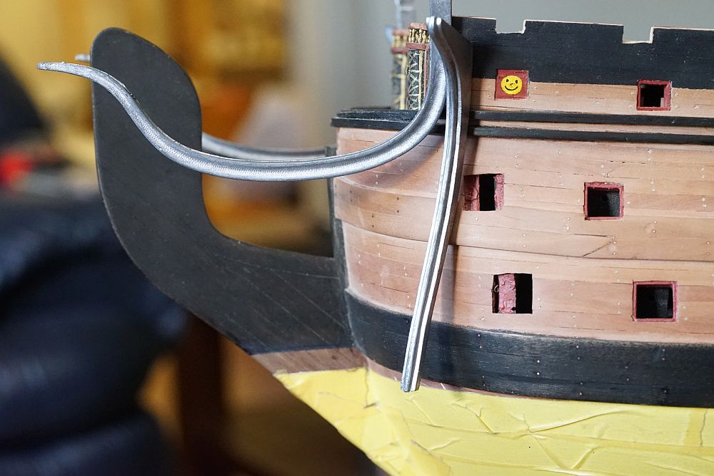
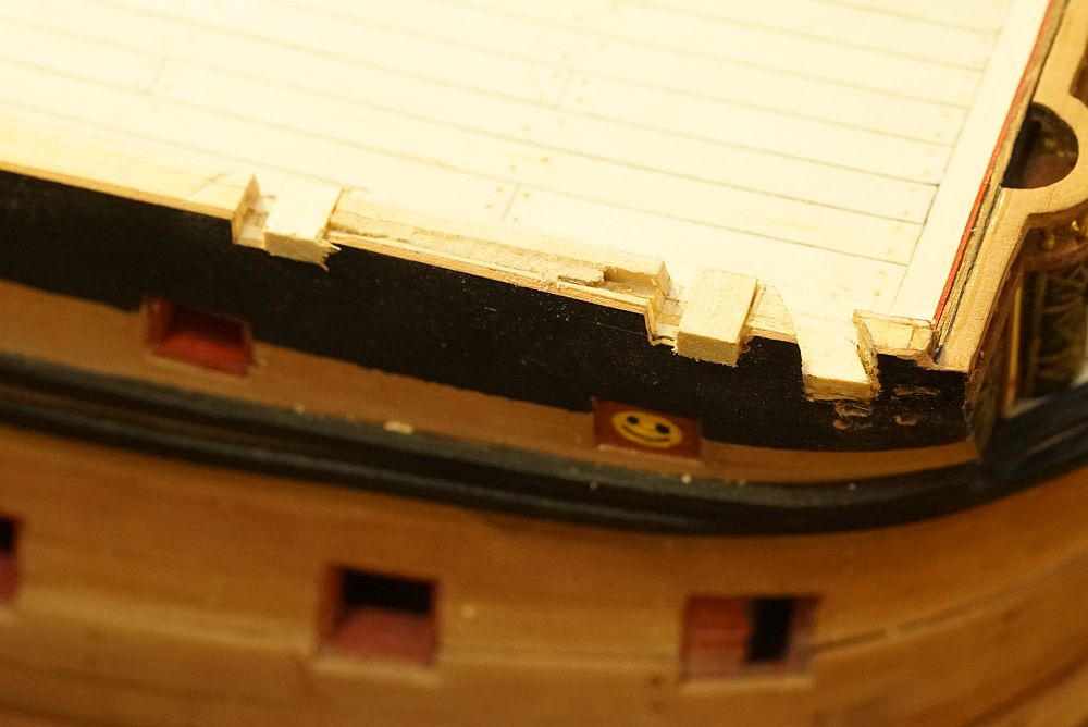
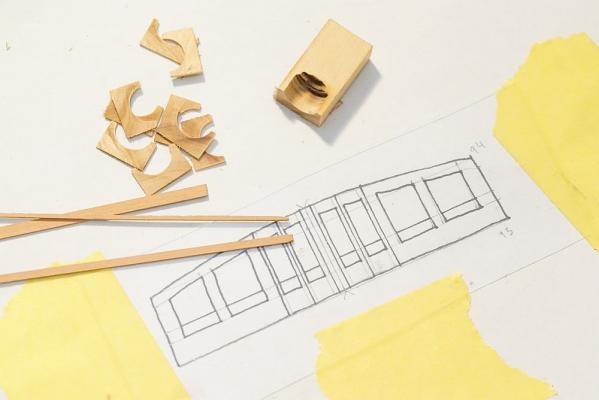
Another update. Having decided to put off the transom for the time being, I am now installing the metal side decoration pieces. The lower limit of the decoration was determined by reading the plans - 1cm above the last wale. I simply took a compass, set it to 9mm, and drew a line exactly parallel to the last wale. I subtracted 1mm because the black line will be hidden under the metal decoration and I wanted some leeway. Other RW builders will note that the plans call for the side of the hull to cut exactly at the termination of the poop deck. I did not think that this would look very nice so I made sure that I had at least 1mm to play with. Each metal piece needs to be shaped to conform to the hull, with holes cut out for gunports. Initially I used a Dremel with a cutting wheel, until I found out that a pair of Xuron nippers did a much faster and neater job. It does leave a nipping mark, but this is easily cut off with a scalpel. Oh yes, the metal is soft enough to be carved with a sharp scalpel! You will also note that the side window (Euromodel part 11260) has been replaced with a scratch built window. This is necessary to let the light from the LED's through. It also looks much better than the Euromodel supplied part. I have completed side decorations to the area of the fo'c'sle but decided to stop for the time being while I install the beakhead. I fabricated a replacement for the Euromodel supplied part. This is Mk. 1 of the piece - I do not like the look of the archways so I removed them. I will be fabricating another replacement soon. Pins were soldered to the railings and holes drilled into the hull to accomodate. As you can see, the railings happily sit on the hull without any glue whatsoever. A cursory examination of the railings tells you how much they need to be bent to fit the beakhead. ... and they need to be bent in three dimensions. Not going to be an easy task. Having determined the position of the cathead support, I proceeded to cut out a hole for the cathead. Uh-oh. As you can see, the cathead will be much too close to the first gun, and this was despite cutting out the gun position exactly as per Euromodel's plans. Here you can see me moving the position of the gunport - glue in a filler block and recut the gunport. While i'm at it, I also found that I cut the starboard poop deck gunport FIVE MM short compared to port! As a result, the metal decoration does not quite fit. Here you can see the repair - remove the decoration, fill in the defect with a block, then re-install the decoration. I will have some thoughts on gunport positioning in the next post.
-
To drill large holes precisely and without accident, start with a small hole. Then swap out drill bits for larger sizes until you reach the size you need. Alternatively, if your drill has a center locator, just drill the small hole, use the center locator, and move straight up to the larger size.
- 786 replies
-
- 6
-
-
- Royal Louis
- Finished
- (and 1 more)
-
Hmm, maybe I am being retarded. I did the rudder so long ago (and it has been covered up with masking tape for so long) that I don't remember whether there were notches for hinges or not. Whatever it was, I don't remember cutting them out.
- 652 replies
-
- 1
-
-
- royal william
- euromodel
- (and 1 more)
-
No cut outs for hinges? That's strange, my rudder definitely had cut outs for hinges! Gee Mark, you have already had one error with your kit. I wonder if Euromodel is now not cutting cut outs in the rudder, or you came out the losing end with Euromodel's QA.
- 652 replies
-
- 2
-
-
- royal william
- euromodel
- (and 1 more)
-
Very nice, Vince! I was debating whether to paint the figurehead gold or go with a colour scheme like you have. What made you decide to go with the colours?
- 593 replies
-
- 2
-
-
- royal william
- euromodels
- (and 1 more)
-
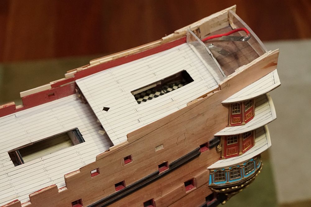
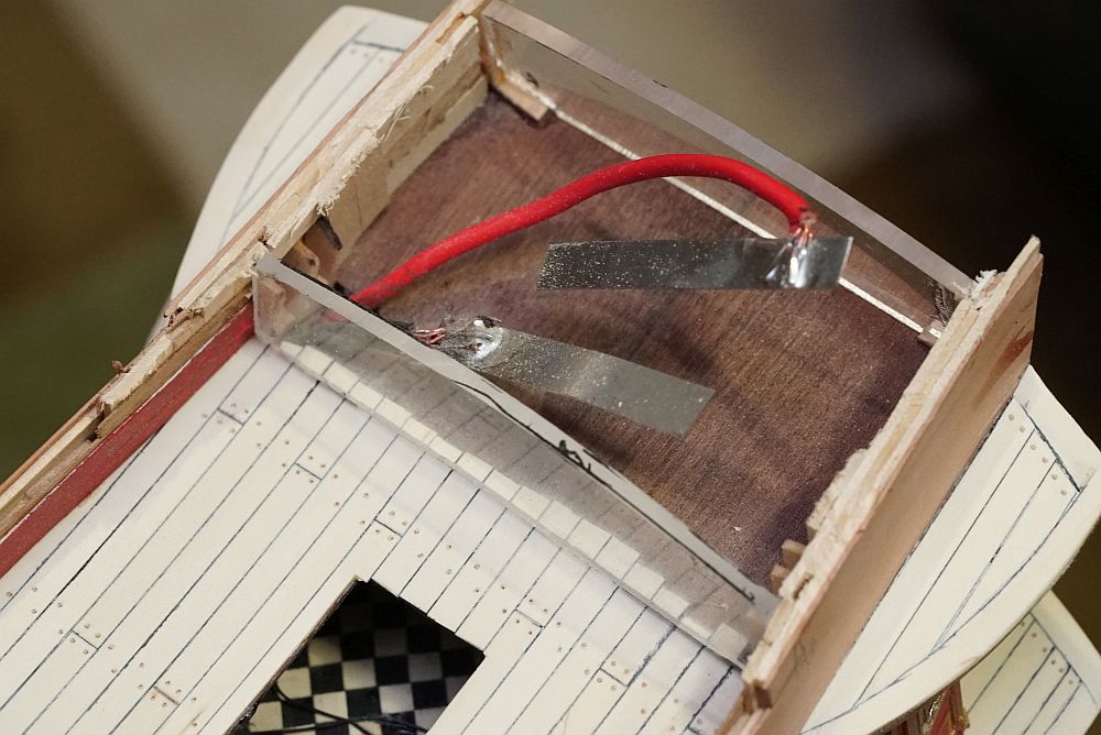
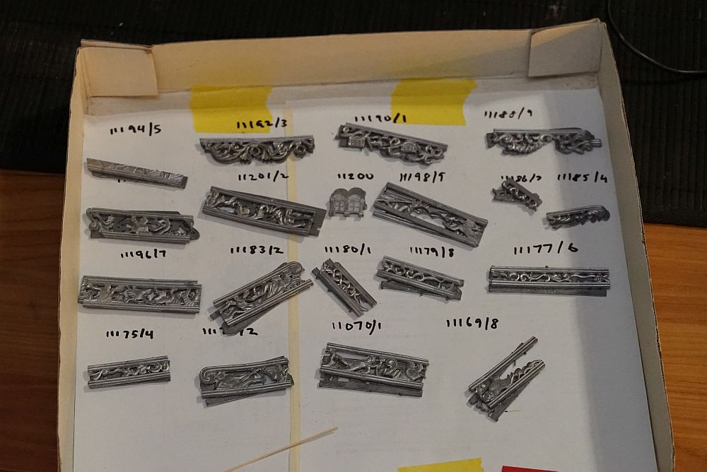
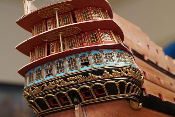
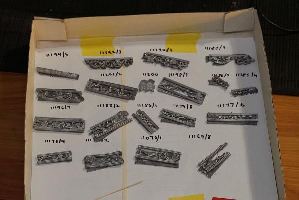
Poop deck is finally on! I am now constructing the poop cabin. The fact that I am planning to light it is posing all sorts of problems and making me find different solutions to what would normally be a standard build. For example, the internal support structures are 3mm thick perspex instead of wood which I would normally use. I have to do this so that light gets through. After finishing the stern galleries, I should proceed to install the transom. However, because I am going to light the lanterns, I would have to install the lanterns as well. The thought of working on the rest of the ship while the fragile lanterns hang off the stern made me decide to put it off for now. I will finish all the major woodwork on the ship first, and then return to the stern. A bottom view of the stern, showing off the ceiling decorations and the column. You can catch a glimpse of the gallery in front if you look through the open door. The internal reinforcement for the poop cabin is made from perspex. I should note that the metal part supplied by Euromodel appears to be lopsided - the curve on one half does not appear to match the curve on the other. I initally obtained the shape by tracing out Euromodel's part, but when I realized that the shape was a bit off, I ended up drawing my own shape. The decorations were dry fitted for testing. The lower line for the decorations was obtained by using a compass and tracing a 10mm line above the wale below it. In fact, the lines for all the wales were obtained this way. I think it is important that all the wales are lined up, otherwise the model might look a little lopsided. The metal decorations are all sorted, cleaned with acetone, painted with metal primer, and ready for painting. Construction of a replacement front face for the poop cabin is under way.


-
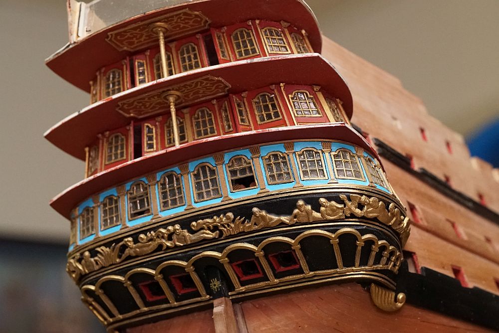
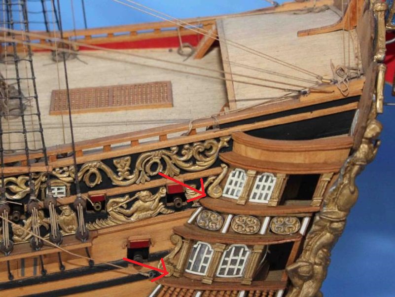
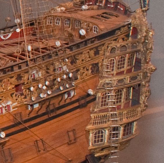
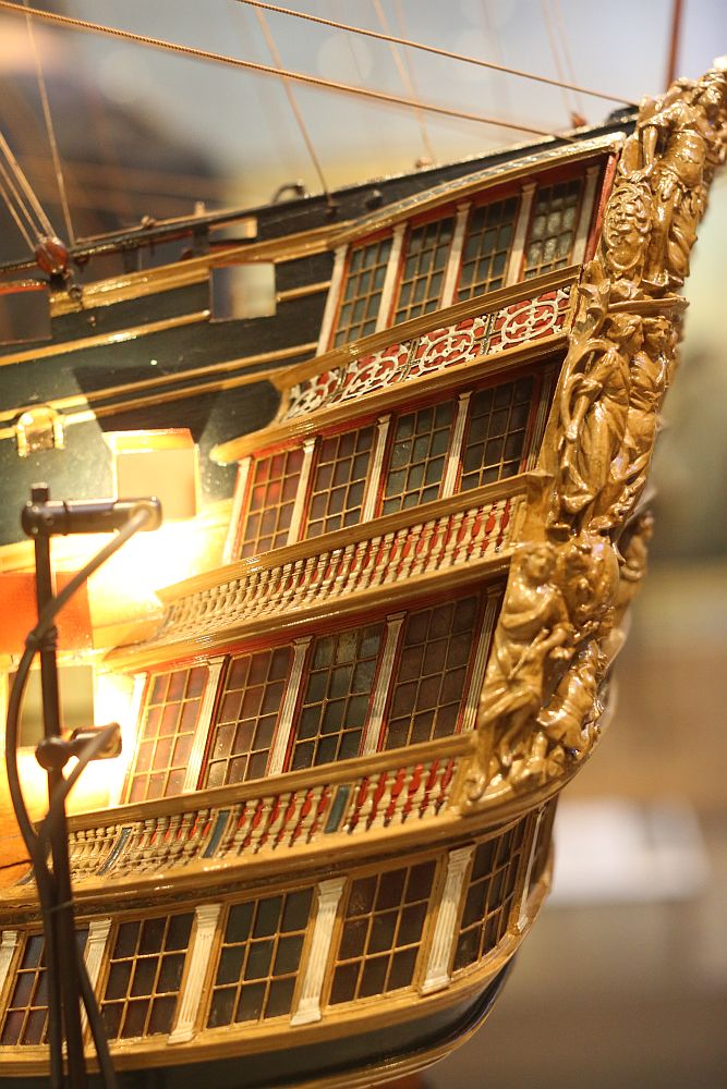
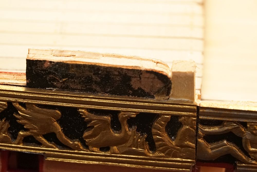
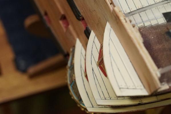
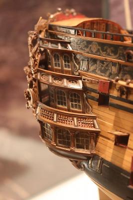
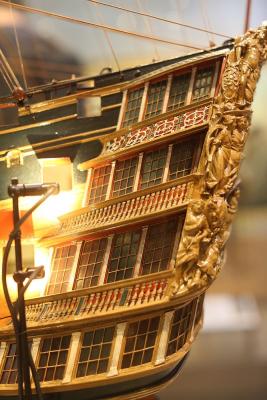
Some progress on the RW. All the decks seem to line up nicely. RW builders will note that I have built in a feature that I have seen in museum models but not in Euromodel's plans. This picture was taken from Euromodel's website. The red arrows show the galleries sitting flush on top of the railings. The plans suggest the same. However, the stern from the NMM's model of the RW does not agree ... ... and neither does the model in the USNA. This is not the RW but the fourth HMS Victory (launched in 1737) - again showing that the galleries are not flush with the railings. I decided to extend the decks rearwards and give them a different profile to that suggested by the plans so that the railings would clear the galleries. Unfortunately, this means that the metal decorations may not fit ... so i'll have to do some surgery on those decorations later.


-
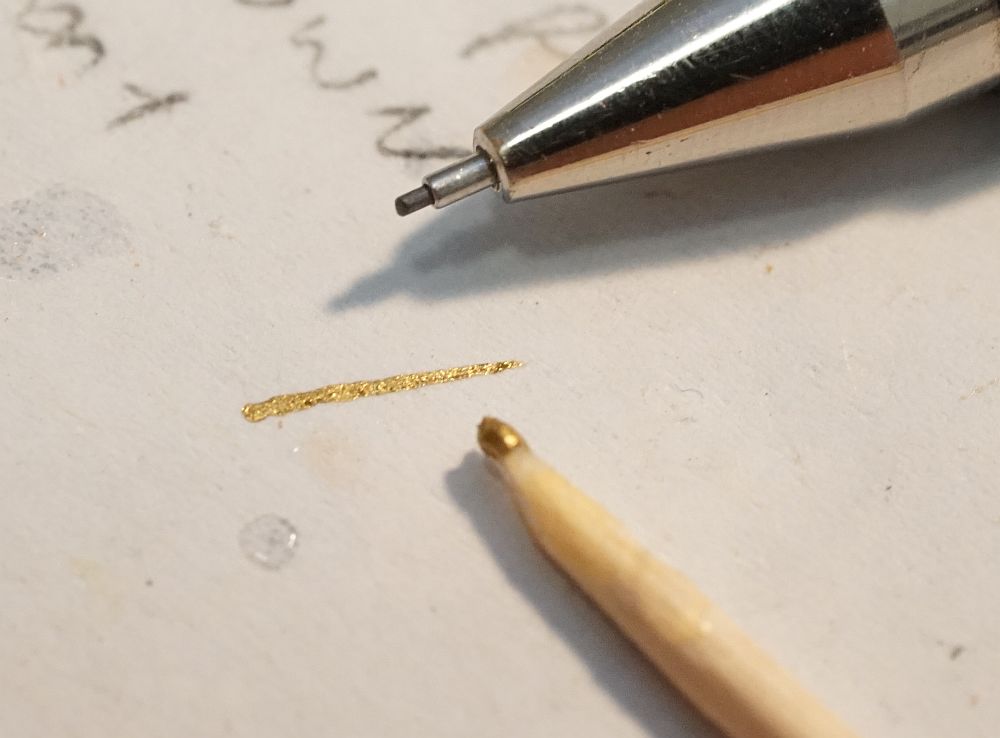
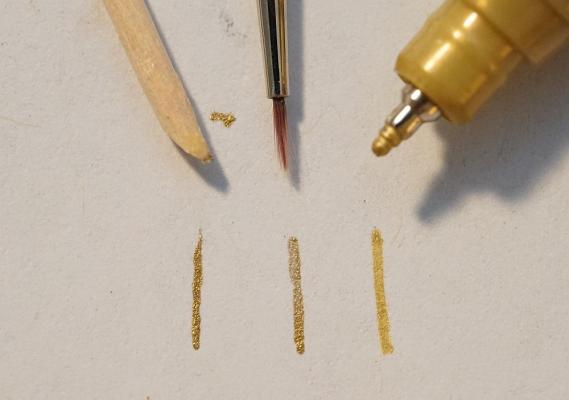
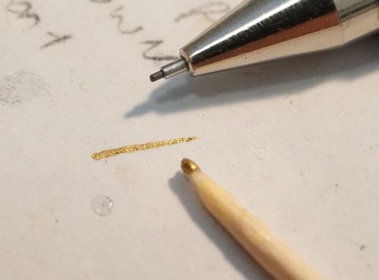
Also, I don't know if you are aware ... but toothpicks make great substitutes for paintbrushes. This is a comparison of a mark left by a toothpick against a 0.5mm pencil. I can leave a thinner stroke if I didn't load up so much paint on the toothpick. You can see that the mark left by the toothpick is neater and denser than both other marks. This is a comparison of marks left by a toothpick, a paintbrush, and the finest nib gold marker I could find. I don't need to tell you the advantages of toothpicks: - cheap and plentiful - no need to clean - every time you need a new colour, just shave a bit off the top and keep using it - superior mark to paintbrush and paint markers! - you are not limited by the paint marker's choice of colour. Any colour you can buy, or mix, can be used
-
Thanks Greg, Greg, Mark, JP, Nigel, and Michael! Your comments are very much appreciated. It's a little intimidating with you guys watching. Anyway, here is a little video I took last week of the top gallery of the stern sliding on. The "pop" when the gallery clicks into place was so satisfying, I just had to take a video to remember it:
-
Thanks Greg, Pat, Brian, and Greg (and welcome to this site!). Greg, looks as if you are considering a RW? I see that you have commented on two of the build logs this evening. Even though I am having problems with my build, I do recommend this kit as it is enjoyable, addictive, and presents different problems for you to solve! Brian, I considered making a post about what Euromodel needs to do to update this kit, but the last time I said something like this, I was accused of bashing Euromodel. So, all i'll say is this: 1. Every builder of this kit, including PiratePete and Keith Julier, have replaced the kit supplied stanchions with their own. 2. They need to supply a Photoetch sheet. Things that should be photoetched: gunport hinges, windows, those little decorations on the verandah of the 3rd deck and poop deck, the side entry door decorations. I am particularly annoyed at the gunport hinges - anyone who looks at them knows they are unacceptable, and it is close to impossible to fabricate so many on your own. As you recall, we got together and asked Rick Shousha to make them for us. Cost was close to 5% of the price of the kit. 3. Pre-cut laser gunports would be nice. ... anyway. A couple of days ago I reached another milestone. The poop deck went on. This is an event one year in the making, I took a bit of a break from posting between April last year till early this year because I was working out how to address those stern windows. Now, all the galleries have been built, glued in place, and the poop deck is on! I'll post some pictures later.
-
Looks perfect, Mark. Did you try dry fitting the decorations to make sure they are OK?
- 652 replies
-
- 1
-
-
- royal william
- euromodel
- (and 1 more)
-
That's OK Brian, the reason I posted that was not to befuddle you with photography geek talk. I did that so that you can understand that most camera flashes on non-DSLR's only expect to be working by themselves and might be confused by the presence of another flash. Flashes adjust light output by changing the duration which the flash fires. The bulb on the flash only ever fires at the same brightness, what changes is how long it is left on. In a flash working in TTL mode, the flash decides how long to remain on (and thus how much light to give) by metering the scene when the shutter is open. In some camera systems, it is quite clever - it knows where your camera has focused on, it knows the focal length of the lens (and therefore it knows the distance between the camera and the subject), and therefore it knows the approximate amount of power to deliver. What it does not know is whether your subject is black (needs more flash) or white (needs less), so that information is gathered in the pre-flash. Slave flash knows none of these things. Not unless your camera knows that it is there and talks to it. What I would expect is this: 1. When you take your picture, the shutter opens and your camera flash fires to take a reading. 2. Slave flash sees the main flash and fires at whatever power setting it has been set at, or desires (depends on what mode the slave flash is in) 3. By this time, the unknown is - whether the main flash has finished taking its reading or not. If it has, then it continues to deliver the amount of flash that it has determined. If it hasn't - then it will deliver much lower power flash because it saw the light from the second flash. As I pointed out in my earlier post (and as Kurt said), the way around this is to operate the flash in manual mode. It is not difficult in a hotshoe flash, you just slide to switch to Manual. But in a point and shoot, it may not be possible to operate your flash manually, so results may be unpredictable. Using a flash in manual mode is very easy, much easier than building a model ship. But I can see why it would be intimidating for someone who does not know how flash works. I should also say that many photographers don't like using flash and don't own flash units at all. This is because flash photography gives you a "flashed look" which is unnatural. The other reason is because flash involves a learning curve and takes a bit of effort and experience to get natural looking pictures. Personally, I am a big believer of flash which is why I took the trouble to learn how automatic flash works, so that it is less unpredictable. But, for someone who is not willing to invest in learning flash, my advice is the same: either get a tripod, or get yourself more lights. Both are far easier to use and involve much less of a learning curve than attempting to use multiple flash units.
-
It may or may not work. The way slave flashes work is like this: 1. Shutter button depressed. This locks focus and exposure - i.e. your camera will now take a picture at the aperture and shutter speed selected. 2. Shutter opens. 3. Flash fires. IF you have a flash set to "master", it communicates with other slave flashes telling them to get ready to fire. Some flashes, like the newer Canon RT flash and Pocketwizards, communicates with other flashes using radio transmission. The older Canon flash and Nikon flash talks to other flash units by light pulses (these are so fast that your eye can't see them). 4. All flashes fire briefly and illuminate the subject. The camera takes a new reading of the exposure through the lens (i.e. TTL), and tells the flash how long it needs to fire. 5. This new information is passed on to the slave flashes. 6. Master and Slave flashes all fire. 7. Shutter closes. If your main flash is not able to transmit exposure information to the slave flash, it may not work. After all, the slave flash does not know how much flash to deliver. If so, you might have to set your slave flash to manual mode (rather than TTL mode) and determine flash power manually. In the old days, you would use a light meter. With digital photography, just keep turning down the power and taking more pictures until the photo looks right. As an aside: there is a very brief delay between the flash firing to take an exposure reading, and the flash actually firing to illuminate the subject. If you are shooting a person, this is enough to make them blink - hence "BEETTL syndrome" - or "Blinking Eye Electronic TTL". The pre-flash causes the main exposure to capture people blinking or half blinking. Doesn't matter if you are shooting a subject that doesn't blink, like a model ship
-
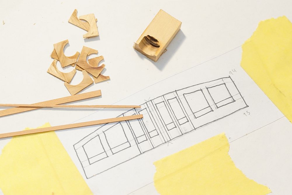
Beautiful work, Mark. I have to say that your accuracy and neatness is on a level beyond mine. That plank solution to positioning the transom support is brilliant, I wish I thought of that. I worked off pencil marks drawn on the hull - nowhere as accurate or repeatable as what you did. Also love the precision of your cut piece. Pete should strongly consider inserting this suggestion into his I-I. Pete, your I-I states that in a real ship, the wales go on first and then the hull planking is fit around the wales. I saw that before I applied my second planking, and considered adding the wales first. In hindsight, it was something I should have done. Those walnut wales are extremely difficult to bend, I could not get them to sit correctly. They protruded at such an angle that at a few points, I sanded through the entire thickness of the plank. All hidden with filler and black paint now.
- 652 replies
-
- 2
-
-
- royal william
- euromodel
- (and 1 more)