Keith_W
-
Posts
1,145 -
Joined
-
Last visited
Content Type
Profiles
Forums
Gallery
Events
Everything posted by Keith_W
-
 Thanks Boyd, Greg, and Pat. It's not the small scale decoration that bothers me, it's all these 1-2mm building errors I keep finding. That the deck is off by 1mm and needs shimming is irritating. And now something else - I found that I cut the gunports on the port side of the ship 1mm off from the starboard side. Normally this wouldn't matter, EXCEPT that I won't be able to fit the spiral staircase on the port side because of intrusion by the gun carriage. I have to do some surgery to remove the gun carriage I have already installed, re-cut the hole, move it back 1mm, then cover up the rest. Fortunately it will be painted over so any repairs won't be too obvious. Something to do tonight. I wonder if it's only me who is making all these errors - none of the other RW builders seem to be reporting any.
 -
Oh yeah, one more thing. To all those who were concerned about Tamiya masking tape. That tape, which has been protecting the painted while hull below the waterline, has been on the ship for more than a year. I removed some to have a look, and it came off cleanly. No glue residue. Hull still nice and white, as good as the day I put the tape on. So - nothing to worry about then!
-
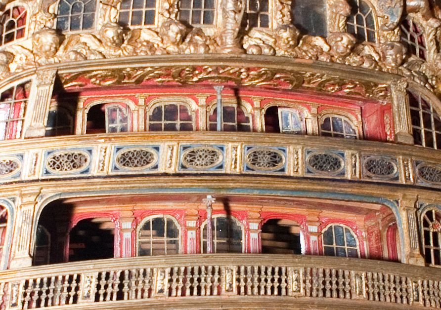
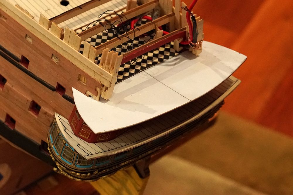
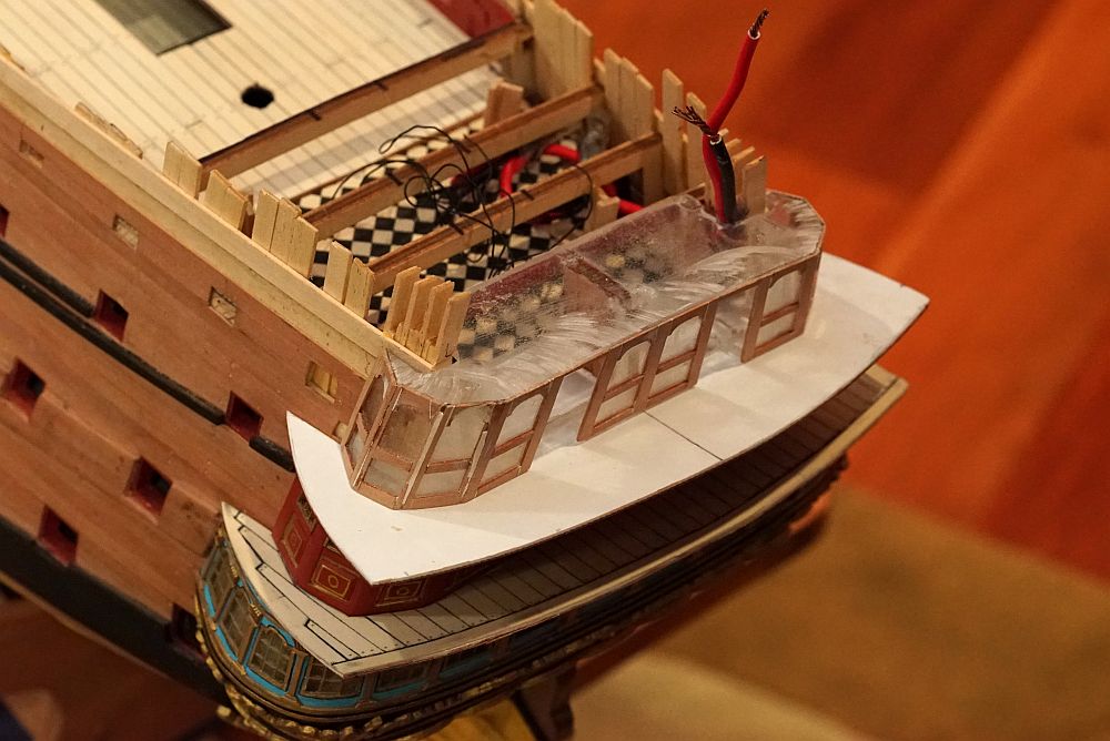
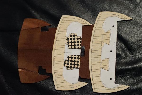
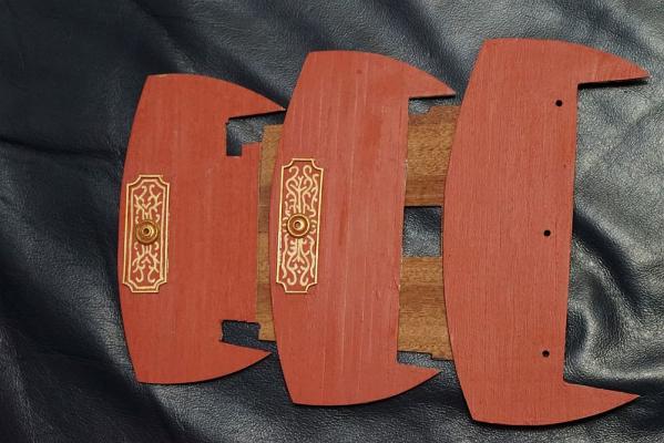
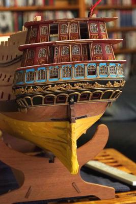
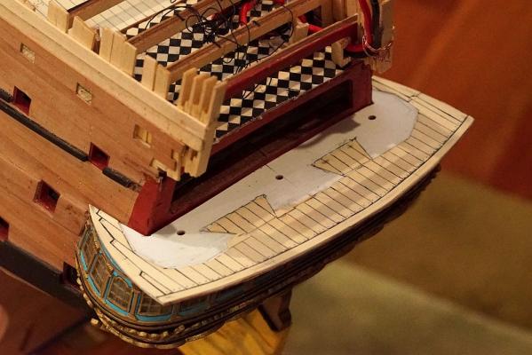
All the decks have been planked over, except the poop deck. I managed to salvage the deck I was planning to discard, turns out that I could remove the planks fairly easily. Wood glued to plastic isn't as secure as wood glued to wood - run a scalpel between the plank and the styrene structure, and the plank just pops off. It leaves quite a bit of CA residue, but that is easily scraped off. Other RW builders will note that the shape of the decks is quite different to that given by Pete in his Interpretive Info. The shape of the deck was arrived by placing the poop deck (which has the correct curvature) on a piece of paper, and Part 53 on either side of it until the rear edges are flush with the poop deck. From that, I traced a line. That gives me the rear line of the deck. For each deck, I placed Parts 51, 52, and 53 respectively. I drew and built the deck slightly oversized - I then placed them on a model then used a ruler to line them all up and shaved them back. Finally, the transom was dry fitted and further adjustments made. You can also see how the decking material accomodates the openings for the doors. You can just catch a glimpse of the interior with the doors slightly ajar, so I did not have to veneer over the whole inside deck. The contours of the planks follow the galleries closely. Slide a gallery over the deck, and it will fall into the planks with a satisfying pop. If you study the rear of the USNA model of the Royal William, you will notice a few features that Euromodel's plans do not have, and make no provision for in the kit. One of them is ceiling decorations and a center column. I have added the decorations. It is nowhere near as elaborate as the USNA model, but good enough in my opinion. I have also turned some columns on my lathe (not pictured). The circle in the center is to hold the columns once they are installed. The galleries have had most of the column decorations added. The last set of columns will be added once I determine the position and angle of the archways (depicted in the previous post). This is surprisingly complex - when I get around to doing so, I will make a post about it. Next to the galleries is a picture of my doors, yet to be cut out. You can see that the doors are assembled on a piece of transparent styrene. A diagram of the door is drawn on paper, then the styrene taped onto it. I then plank over the plastic and paint. When done, I just cut it out and install. ... and lastly, a couple of pictures of the model as she is. Probably about five more things to tick off my list, and then the poop deck goes on.


-
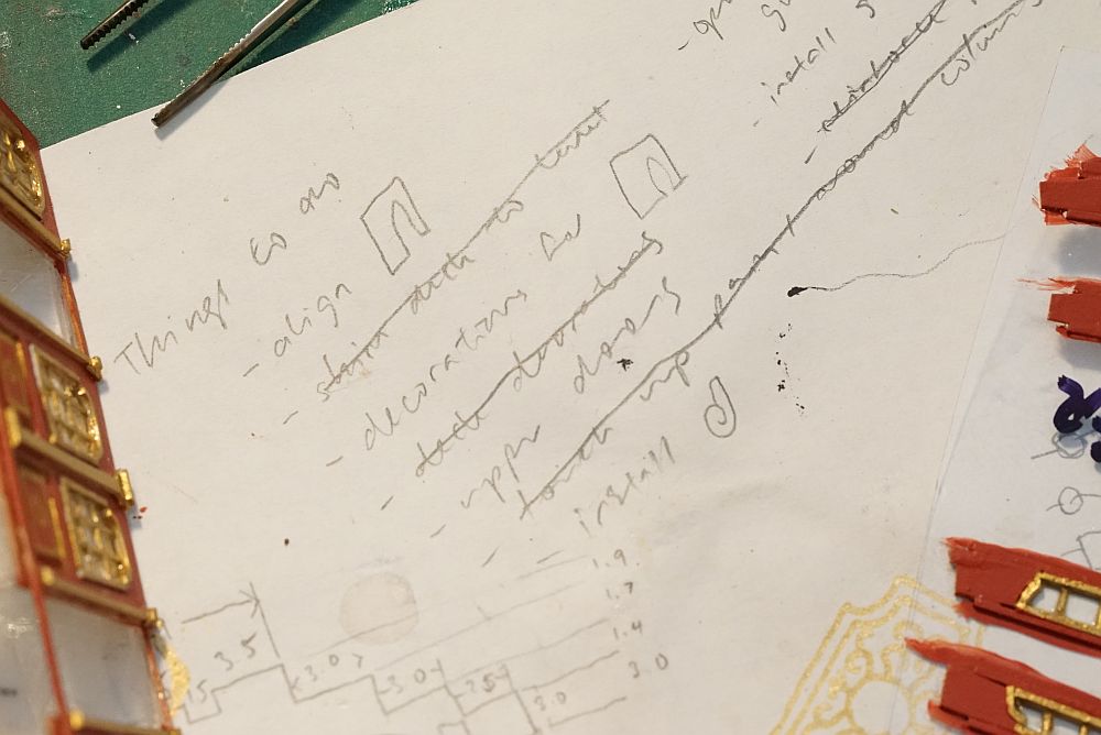
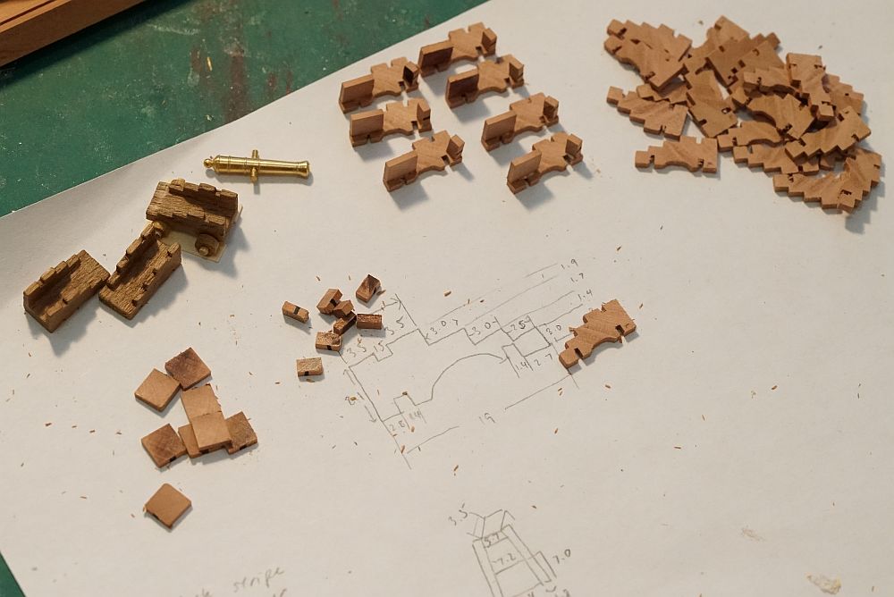
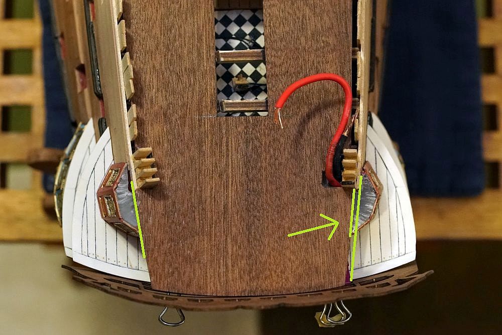
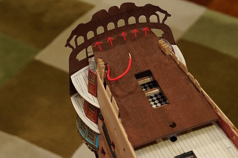
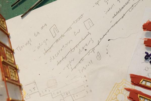
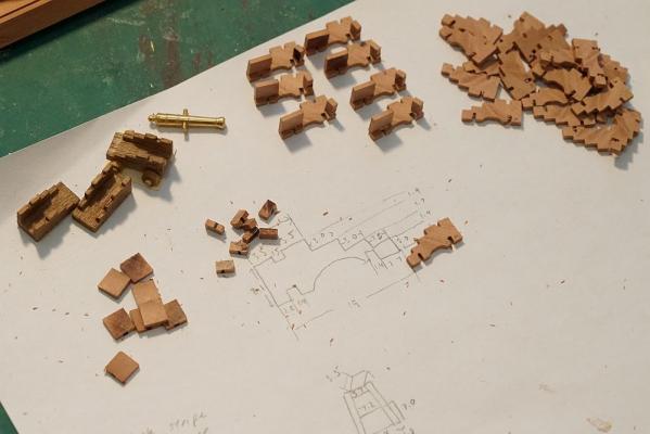
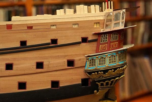
Time for an update. Over the past week, it seems as if all I was doing was taking care of little details in preparation for the installation of the poop deck: ... indeed there is quite a list. To make sure I don't forget, I had to make a list and tick them off one by one. Every now and then i'll think of something else and add it to my list. You can see my modelling style, I build my features on an A4 piece of paper (plenty to be recycled at the office). Whenever I think of something, I write it down. If I need to draw something, I just draw on it. It also catches all glue stains and keeps my self healing cutting board clean. First on the list was to make a set of cannon carriages. This had to be done because a pair of cannon carriages have to be installed before the poop deck goes on. If you check my post from February last year, I explained how I made them. On the left are kit supplied carriages. On the right are my scratchbuilt ones under construction. Because (horror of horrors) my deck features are a slightly different size to the Euromodel supplied parts (but correct according to the plans), I had to construct a new archway using the kit supplied archway as a template. The top gallery, seen in the previous post under construction, has now been completely veneered over and the windows have been installed. Whilst checking the poop deck for fit, I noticed that the hindmost part of the deck was off by 1mm! Not much, but enough to cause problems. The solution was to cut some material to bulk it up. The real transom was dry fitted after I curved it with a steam iron. As you can see, it aligns perfectly with the poop deck ... ... and all the decks below. The sharp eyed will notice that the rearmost gunports have been closed over. This is because I positioned them incorrectly. The metal side decorations feature holes cut out for gunport locations! If your gunport holes are off by a fraction, they will not line up with the metal decorations! Mine were off by just 1mm. That's enough to make me close them over and cut them out again when I dry fit the side metal decorations. The upper wales have been brought all the way back to the stern, with a tiny gap cut for metal decorations.


-
Just found your build - looks great! I can't think of a reason to do the rails before the deck. Have a good look at your plans and proceed. PS: love the Buddy Bradley avatar! Looks as if i'm not the only Peter Bagge fan around here!
-
Not sure how I missed the start of your log, but i'm certainly following now. This model is on my bucket list, so I should pay attention!
-
Looks great, Vince. I am not looking forward to this part of the build myself.
- 593 replies
-
- 2
-

-
- royal william
- euromodels
- (and 1 more)
-
Perhaps Pete is right, Mark. After I shimmed my pieces, I ended up with about 1mm space for the decorations. They did not fit exactly. Perhaps you should proceed as Pete suggests, and then dry fit the decorations. If you have no space, you can always shim.
-
Very nice Mark, and don't forget to shim!
-
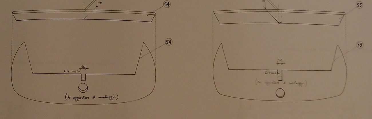
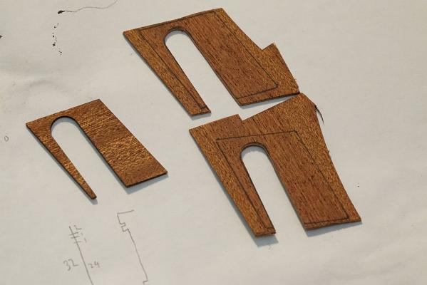
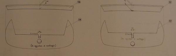
Mark, that is definitely an error with your kit. It looks as if they cut the correct profile to the wrong thickness of wood. That piece which has the profile of Part 55 (but is 13mm) ... MUST be 18mm. This is absolutely vital. Otherwise - not only will your stern look strange, but the decorations won't fit. Your options: 1. Make a new part of correct thickness. This is simple to do if you own a scroll saw. 2. Shim Part 55 and shave Part 54 till they are the correct thickness.* 3. Contact Euromodel to ask for a replacement. This may be a good time to buy more half guns and gratings. You would have seen from PiratePete's I-I that Euromodel do not supply enough grating material to finish the build according to their plans. I am not able to confirm this, but I purchased more gratings just in case. * Note that both pieces are curved - the center is 2mm raised compared to the sides. You can confirm this by studying the plans, and by looking at the bottom edge of the pre-cut mahogany ply transom piece. Even the standard parts provided by Euromodel need shimming. I shaped Part 55 so that it was flat at the bottom, but 2mm raised in the center. This required a 2mm shim. As for part 54, I curved both top and bottom surfaces - 1mm shim on top in the center, and 1mm on bottom on the sides. Make sure you take this into account when you are shimming. Another word of warning for your build. You will see that PiratePete exhorts multiple times in his I-I that the inclination of the transom should follow the inclination of the wales. I see that you are planning to build the transom before you install the wales. I did mine the other way round - wales went on first, then transom. This was so that I could constantly remind myself of the correct inclination of the transom. Also, those walnut wales are a real monster to curve and fit. You can decide if you would rather try to fit them precisely to the transom whilst struggling with drying glue and not being able to clamp. Or if you think it's easier to glue the wales on first and then shave them later to fit the transom. For me, it was a no-brainer. If you decide to fit the wales after the transom, I urge you to mark out the line of the wales and make sure you follow the correct inclination when you are building your transom.
-
Whoopsie. I would cut out the wood next to the gratings and cover up the hole at the end of the frame.
- 786 replies
-
- 6
-
-
- Royal Louis
- Finished
- (and 1 more)
-
Hi Mark, Piece 55 is the THICKER piece, and it goes on the bottom. The plans indicate this, and PiratePete's I-I also indicates this. Piece 54 is the THINNER piece, and it goes on top. If you look at post #147 (page 8) and post #184 (page 10) in this build log, you will see how I fabricated these transom pieces, as well as a side profile picture of my build clearly showing that the thicker piece goes on the bottom. I am not sure why the outline of your pieces do not seem to match the outline given in the plans. I can tell you that there was no confusion which piece was which with mine. The pieces supplied in my kit matched the plans perfectly. As I recall, even down to the 13mm and 18mm thickness. Perhaps yours were accidentally cut with the correct profile and the wrong thickness? This is the relevant diagram from the plans: I have plenty to say about shaping these pieces, they were a real headache. In retrospect, one thing I should have done for others was to photograph the completed piece superimposed on the plans, so that you can check for yourself what my final shape was, vs. what the plans recommended. It is too late now, the pieces are glued to the model - but I have not yet glued over them! If you have any requests, feel free to ask. I might have some additional photos stashed away that might show the feature you are looking for. (edit) I may be able to photocopy the plans, cut out the outline of the pieces, and take a picture of them sitting on the model. Would you like me to do this for you?
-
Gulp, it looks as if the big guns on this forum are watching this build now! It is a little intimidating, so I better not slip up now! Thank you so much for all the likes and comments everyone, it is very encouraging. Constructing those stern galleries was my biggest concern prior to buying this kit. I knew what those metal plates would look like, from studying pictures on Euromodel's site and a few other RW's which I googled. I also knew that any mistake with the construction of the hull, even by a couple of mm, would have me either shaving off height from the metal plates, or somehow trying to add height to it (e.g. making the decks thicker!). I am not so brave as to set the vertical and bottom limit on the stern by constructing the poop deck and attaching the lower transom as some other RW builders have done. Even though I knew I would be attempting to build my own galleries, I still wanted insurance in case my efforts failed and I had to use those metal plates. So Mark - I wish you good luck with your build. I am following your updates closely and thinking to myself that I wish I had done that. John, having built a few of those galleries now I can tell you that this technique definitely works. The biggest issue is to find a supply of plastic that is compatible with CA glue. It actually does not matter if the CA fogs up the plastic - because, a dollop of canopy glue turns them clear again! It's amazing! The ONLY issue to be concerned about with plastic and CA is that the CA does not make it brittle! It can sometimes take up to 24 hours before this becomes apparent - the plastic gets so brittle that it crumbles and cracks in your hand. Finding plastic that is compatible with CA accelerant is another matter. Best not to use it. I find that a single spray of accelerant is enough to make some plastics brittle. I apply the veneer strips to the plastic base using as little CA as possible. First, I CA up the wooden strip which I have pre-cut. I then wipe most of it off by smearing it on some paper. I apply it to the clear plastic carefully, then dab off any excess CA with tissue paper (if you work fast, the tissue paper does not stick to plastic).
-
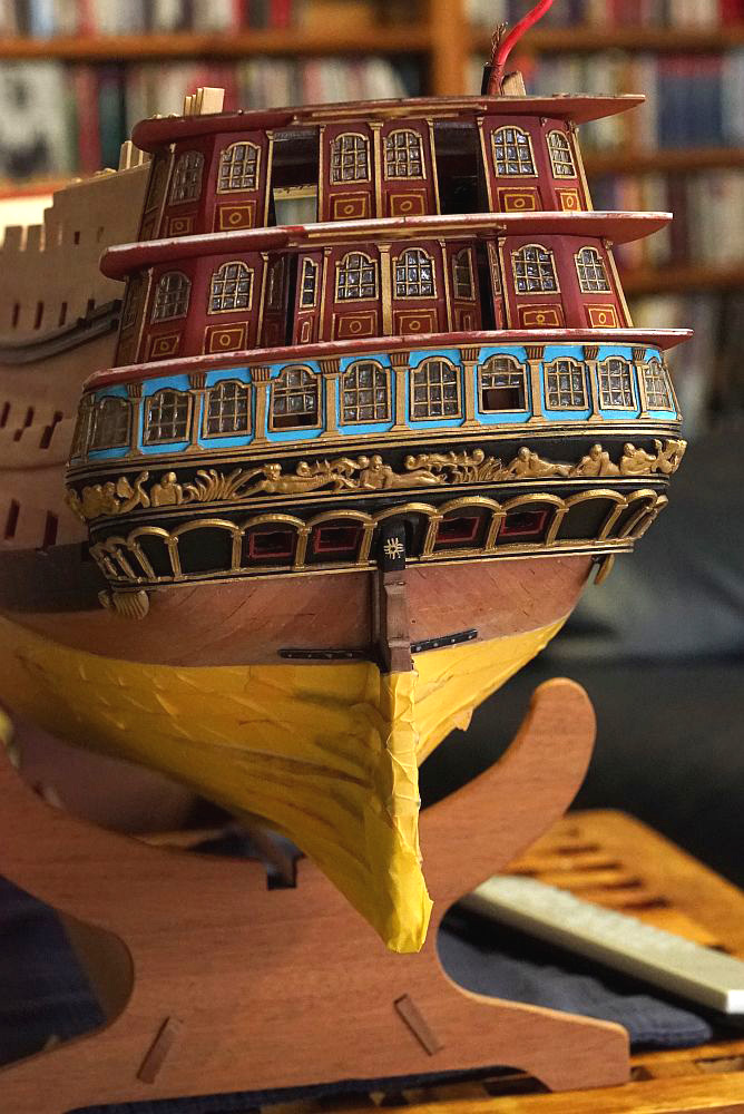
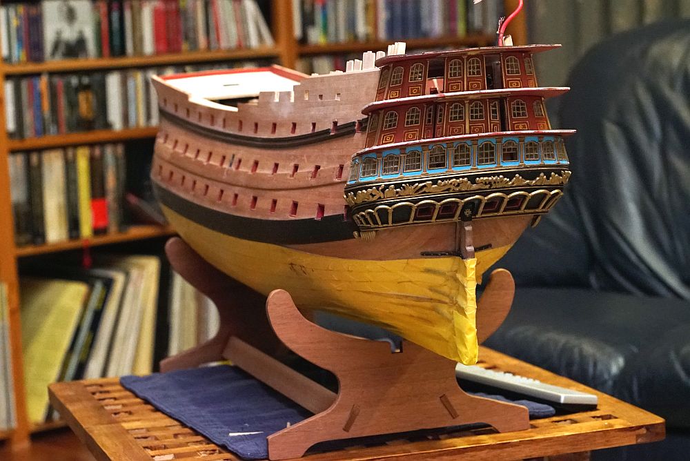
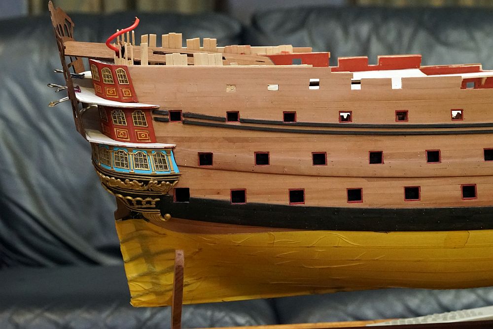
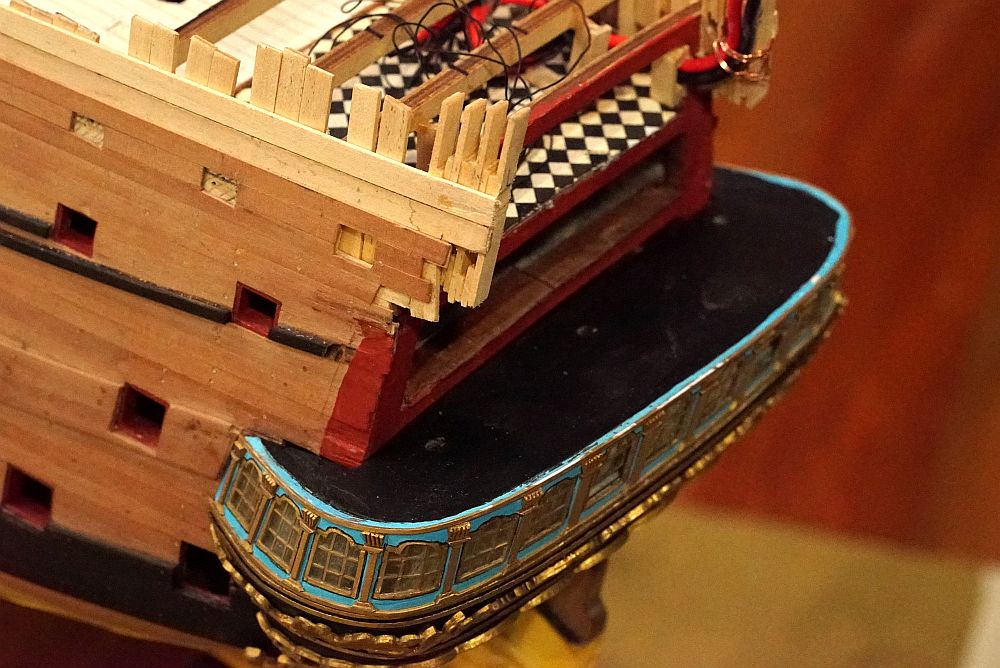
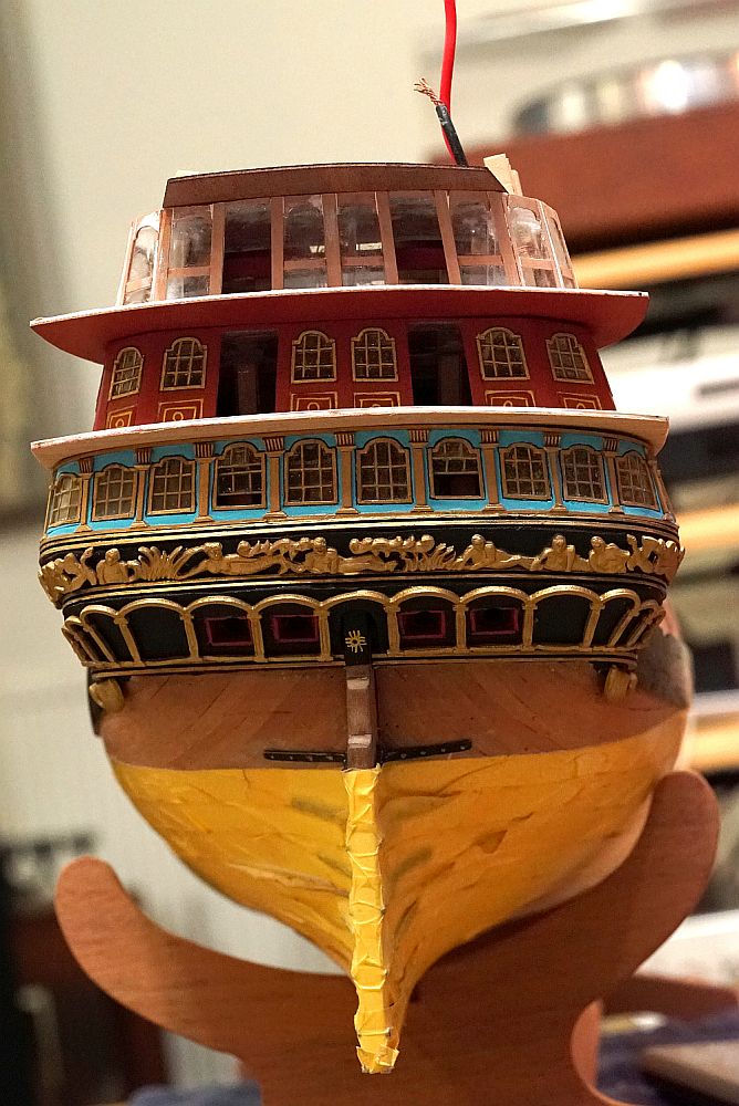
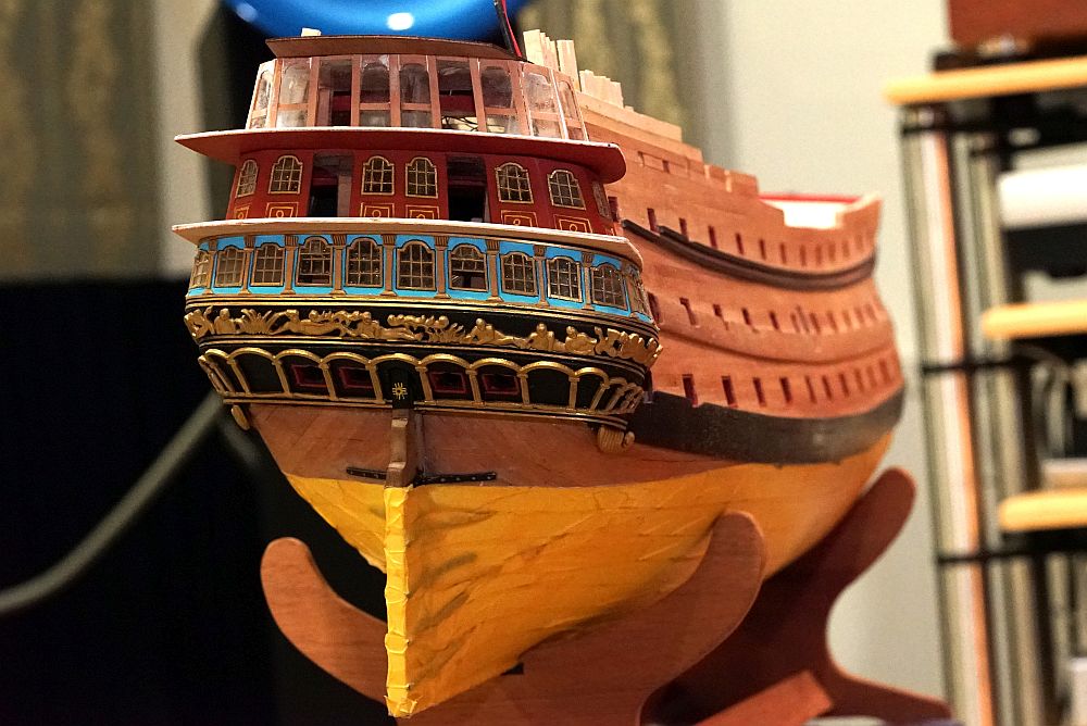
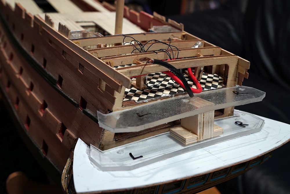
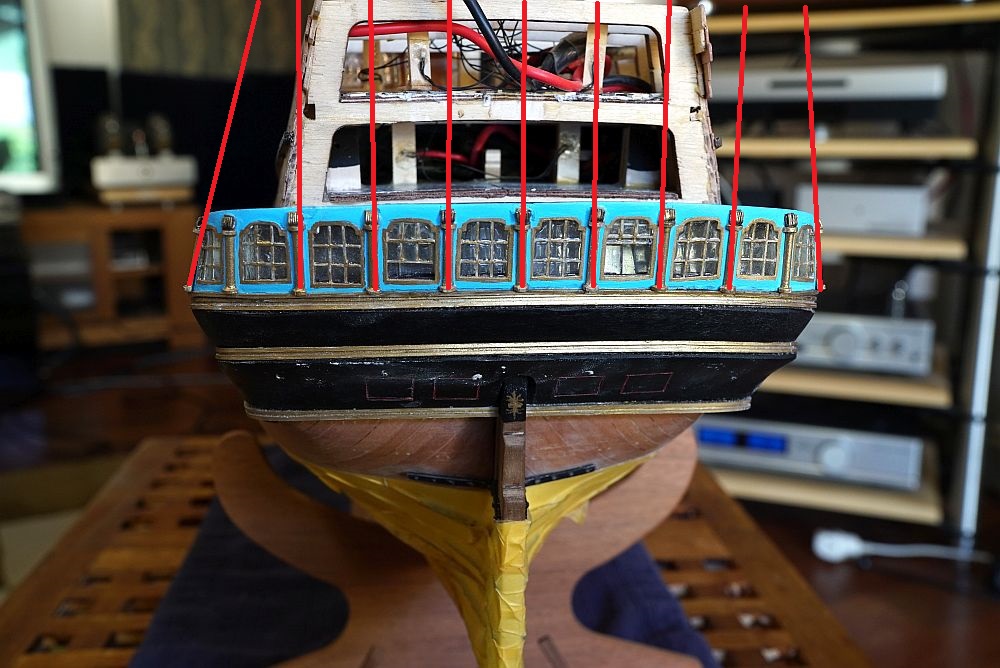
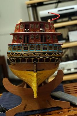
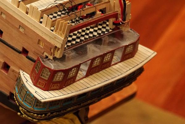
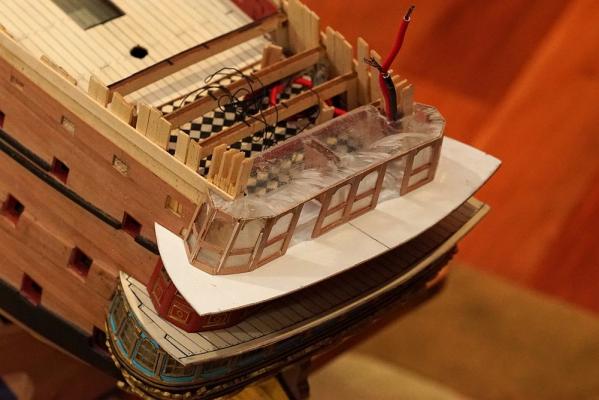
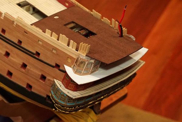
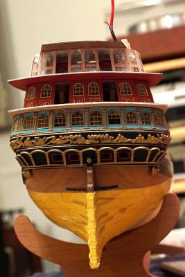
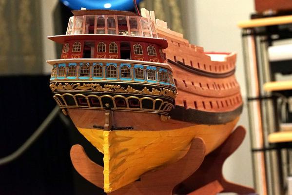
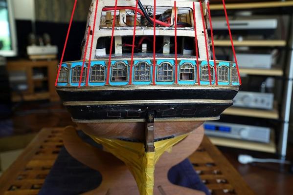
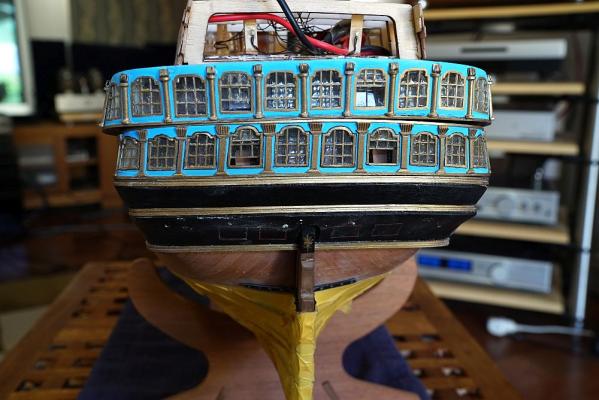
A number of decks have now been progressed. Not yet completed, because some of them need to be touched up or redone. Here they are, from the bottom up - incidentally, also showing how tight I have made them fit against the bulkhead: First, the bottom windows which have been the subject of my last few posts. The middle deck. Note the pattern of the planking. By this stage I realized that I was at least 2mm too tall, so I was trying to save half a millimeter here and there. The deck is carefully planked around the rear gallery to save some height. Despite this, this part is destined for the rubbish bin. I do not like the effect of the joggled planks, and it turns out that I made this deck about 2mm too wide (which means that when it comes to shave it, it will cut into the joggled planks). I suppose I could ignore it and hope nobody notices ... but I would rather redo it. Next, the rear gallery. Columns and doors have not yet been added. The upper deck. The bottom has been planked, but not the top. You can see the supports for the poop cabin (to come in the deck above). This is unsupported by any structure, so I decided to make a wooden lattice structure to strengthen it. The upper gallery. As you can see, still under construction. Note the hole cut through the gallery to accomodate the wooden lattice and the cabling for the poop LED's. And finally, the poop deck. Despite all the effort to save height, I am off by 1mm. The poop deck will have to be shimmed by 1mm to raise it to fit the pre-cut transom. This is the advantage of building the features together (as opposed to constructing the poop deck first as some other RW builders have done) - I am able to adjust features as required. I also decided to excavate some holes for the rear gunports and attach the rear decoration at this point. I have stolen VinceP's idea and added a black line to the strip. The decoration was hand drawn after a night on the booze. They will have to be painted over and redone. An important feature of the rear galleries is that they slope according to the shape of the hull. You can also see that I have maintained the imaginary vertical line that goes straight through the windows of each deck. Likewise, the sideways view shows that the middle and upper galleries are perfectly aligned. Also note that the each deck follows the line of the wales - an important feature that PiratePete exhorted upon in his "interpretative info". ... and this is where we are now Note that nothing has been glued, what you see above is "only" a dry fit! The parts have been cut so nicely that they just slot straight in and hold their shape without glue. I hope to have all the galleries finished by this weekend. There is a model show coming up, and I hope to have the whole stern finished by then.


-
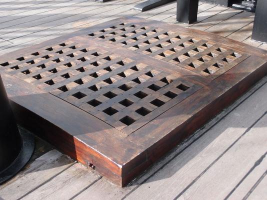
These are grates from HMS Victory. I took this picture when I was in Portsmouth a couple of years ago. As you can see, the grates can be lifted up. But the coaming is fixed.
-
Are you suggesting that I am building it so slow that i'll be dead before I start the rigging? Don't worry, i'm still quite young!
-
Yes Brian, i'll see you on Wednesday! I know it's a bit of trouble, but would you be able to bring your RW along? There are some things on your ship that I would like to take reference from.
-
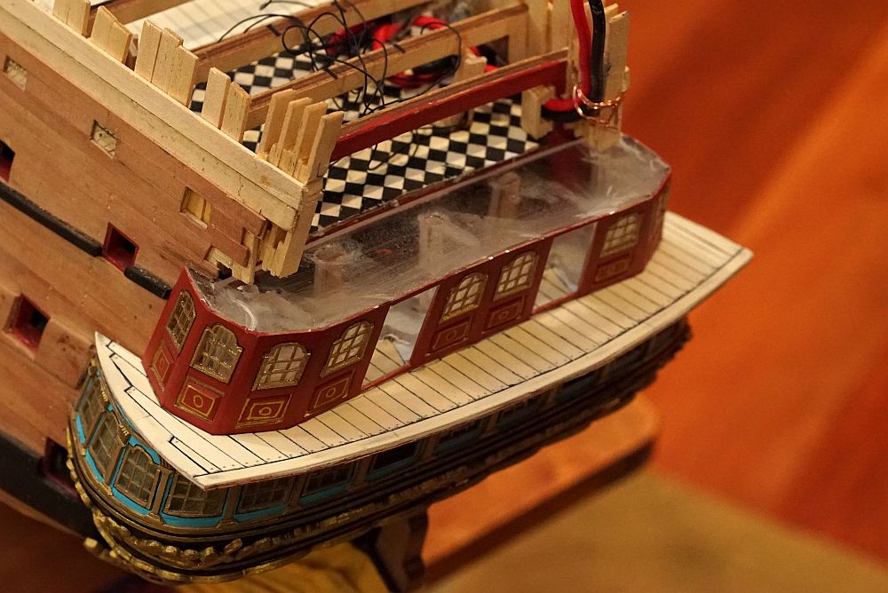
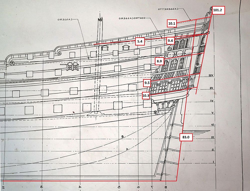
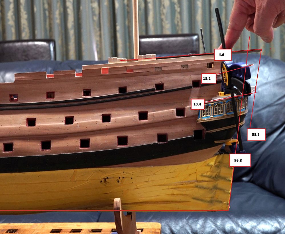
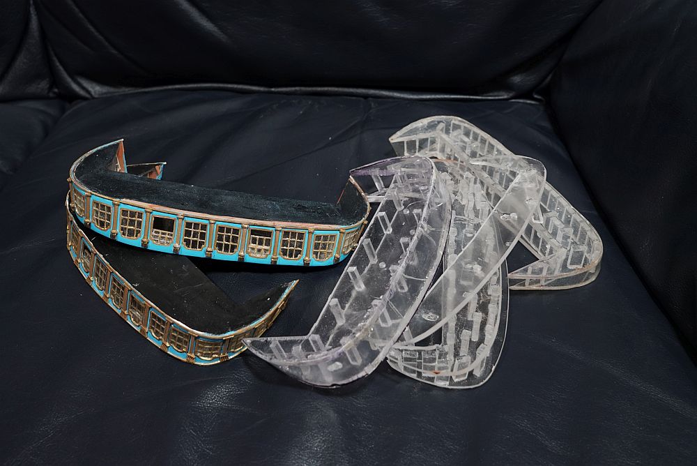
With that done, it is time to turn my attention to the construction of the next level deck. This is where I am up to at the moment: 1. The lower deck windows have been completed (see above post). 2. The middle deck verandah (is that what you call it?) has been cut out. 3. Perspex blanks of the middle deck gallery have been shaped. Here you see them being tested for fit. There is a plywood spacer of exactly the correct height helping maintain the upper part in position while I check for alignment. Also note the three pilot holes drilled through both parts - passing a dowel through the blanks brings them into perfect alignment. 4. A cardboard blank of the upper deck verandah has been made (see below). Before I proceed, I thought it would be prudent to check that I have all the angles correct with reference to the plans. I used the keel to take the horizontal reading, then rotated the image in Photoshop. One thing which has troubled me for a long time is the angle of the poop deck (see below). All the decks are inclined with respect to the wales, but not the poop deck. The poop deck is inclined with respect to the other decks. This is quite unnerving when you install the poop deck, and see that the angle of all the lower decks seem to be off. Not so! this is correct!. The plans say so! Once again, image rotated with Photoshop using the keel as horizontal reference. You can see that the angles are way off with respect to the plans, but to be fair I didn't really take the trouble to center the image correctly (my fault!). By eye they look correct. Note that the angle of the transom is different to the angle of the rudder. There is a substantial difference in angle - 18 degrees! I did not realize this and have been building the transom to accept the same inclination as the rudder. Not too late, all of the decks only exist as prototypes!


-
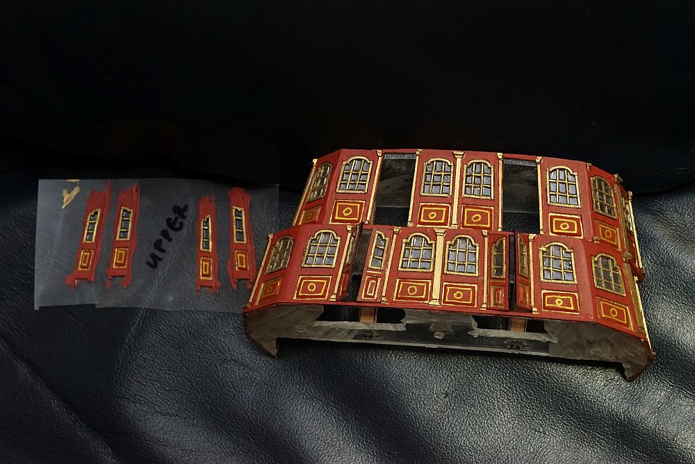
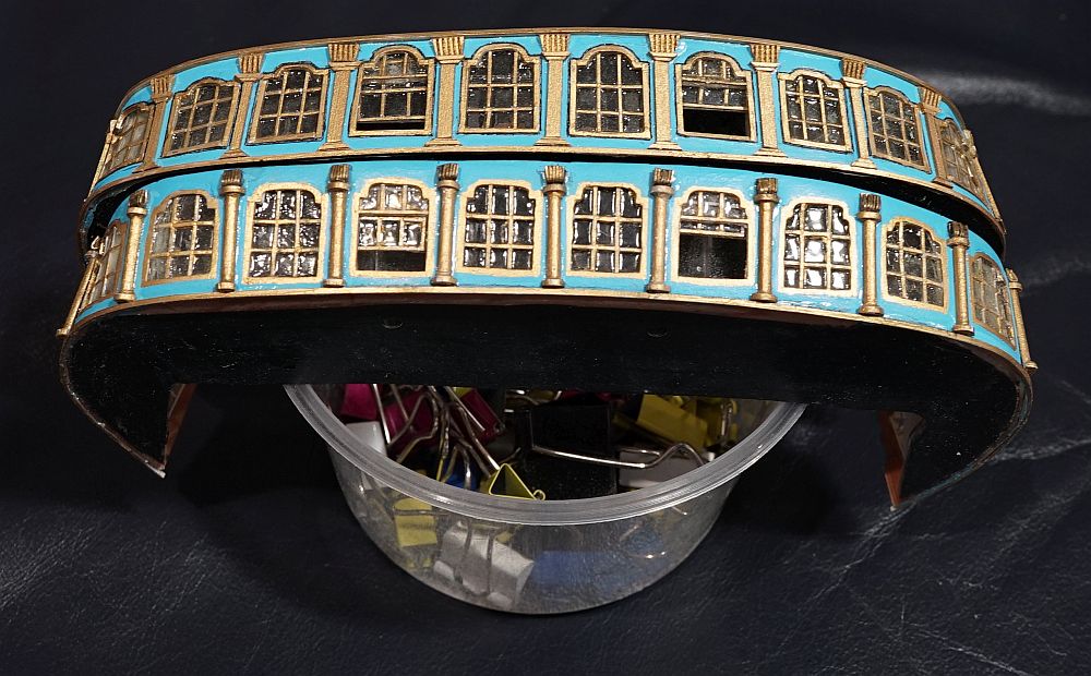
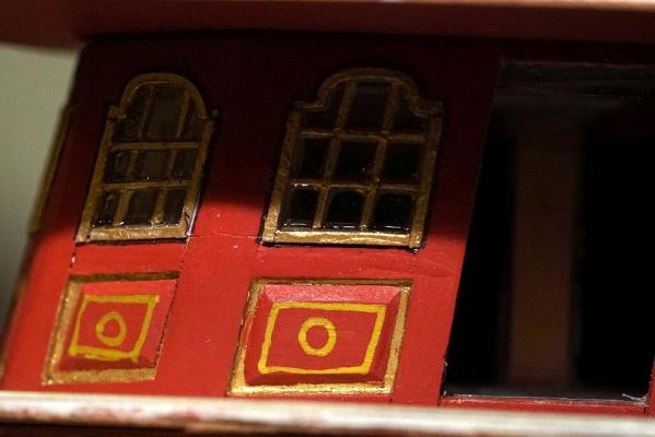
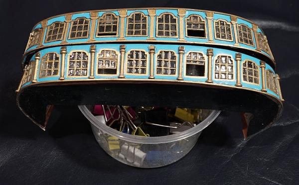
Why, here we are again. What's kept me so busy? VERSION SIX OF THOSE BLOODY REAR WINDOWS, THAT'S WHAT!!! You can see that I have actually completed one set of rear windows but decided it's not good enough and attempt another one. Why? Because I didn't read the plans properly. These are the previously completed set of rear windows. I had a feeling that something was not right with the look of the windows, that they looked kind of lopsided from some angles, but OK from other angles. It took me a while to figure it out ... that's when I realized that I had aligned them vertically when I built them. The plans actually call for them to be aligned according to the shape of the hull, tapering towards the apex in perspective. I went through and made another set, paying attention to this detail which I overlooked the first time around. I didn't show construction pictures because you know full well how these are made from my previous failed attempts. You can see from the above several features of the new part (in the first picture, the new part is sitting on top, in the second picture, it's on the bottom): 1. The angles of the windows which I have already talked about. 2. The new part now has an interior. You can vaguely see it in the second picture. 3. The column decoration on the new part looks neater. I tried a different approach this time. 4. The windows are now outlined in black paint. It makes them look more prominent.


-
She looks fantastic, Ulises! Your wife allows you to put your model on your bed? Mine would scream at me to get that dusty thing off the bed!
- 786 replies
-
- 5
-
-
- Royal Louis
- Finished
- (and 1 more)
-
Oh, you moving to the big country? Which city? (Melbourne is the home of fine ship modellers!)
-
Artesania has the following strengths: - They have a range of models that suit everyone from beginners to more advanced builders. I can definitely recommend some of their easier kits as an introduction to the hobby. - The instructions are decent. Not as good as some others, but they are OK. You usually get a booklet or sheet with colour photos, and another sheet of instructions in poorly translated English. These instructions are sometimes close to incomprehensible, especially if you are not familiar with nautical terms. The plans are also decent, but rigging instructions can be vague or poor. - The wood is great quality for the price of kit you get. They normally supply mahogany, sapele, and walnut - all very attractive modelling woods. - The accessories are packaged in nice plastic containers (a bit like a fishing tackle box), unlike some other kit makers where they are supplied in stapled plastic bags. For example, the Euromodel kit I am building is in the upper scale when it comes to kit pricing - yet the fittings are in plastic bags. - They actually provide you with enough material to finish the model! - No plastic! (I'm looking at you, Billings) They also have some weaknesses: - They recycle fittings between models. This may result in some models having over-scale balustrades or fittings, or too small blocks. - Many of the fittings are so-so and would benefit from scratchbuilding or aftermarket replacements. - Most of their ships are fictional and are not particularly historically accurate. It doesn't matter if you are only after a nice model (you will certainly get a nice model from an Artesania kit!) but it matters if you care about history.
-
Thanks Greg, but given that there are some of MSW's finest modellers watching this thread I am kind of intimidated. I am actually ... redoing the transom. Yes that's right, I finished making the part, decided I wasn't happy with it, and decided to do it again. I have very little time these days so this decision was not taken lightly.
-
Hi Mark, looks really great. Great idea using those belaying pins, although the thought of filing so many of them to fit the railings makes me a little weak kneed! As it turns out, I am using the exact same gold paint as you. How did you get your lines so sharp and neat? Did you mask off every area to be painted?
- 652 replies
-
- 1
-
-
- royal william
- euromodel
- (and 1 more)