


NMBROOK
-
Posts
2,305 -
Joined
-
Last visited
Reputation Activity
-

 NMBROOK reacted to Keith_W in HMS Royal William by KeithW - Euromodel - 1/72
Here are a few vanity shots ... just for fun.
Taken in the backyard on an Australian winter morning. Yes, the sun is out. Grass is green, and the sky is blue. But it is really cold!!
The other side. Decorations have been placed all the way to the front with the exception of the last piece. Once the beakhead railings go on, the last piece will be placed. The position of all the gunport holes have been finalized and cut out.
Note also the gaps in the decorations that I left for the fenders. I have not shown a picture of the fenders yet, but they have been cut, sanded, and ready to be installed. Because the top of the fenders need to reach the cap railings, the top of the fenders have not been trimmed. I do not want to leave the tops sticking out while I work on the rest of the ship, so I will leave off installing the fenders until I am ready to install the cap railings - which will come after the transom is completed.
You can also see that the pear planking in the front is a lighter shade than the rest of the ship. This is because it has been freshly sanded in preparation for the beakhead railings to go on. The darker shade of pear is what pear looks like when it has not been sealed and has been absorbing oil from my fingers for more than a year.
From the back. You will note that the top of the decorations look a little irregular. Can't be helped, that is the nature of what was supplied in the kit. Once the wooden caps go on, everything will be sanded until it is flat.
The completed repair of the re-positioned gunport I showed in my previous post. I saved all the offcuts from the decorations in case I might need them. In this case, I lengthened the decoration by gluing in parts that I had to remove from other pieces to accomodate gunports and so on.
Close up of the three windows which I replaced. In hindsight I could have left on Euromodel's supplied smaller windows instead of removing them - they are barely noticeable when the model is viewed in full. And my replacement doesn't look that great.
You can also see that I have filled in the gaps between the decorations with some epoxy putty and painted it over. Keith Julier says that the joints are almost invisible once you do this. Well, i'm no Keith Julier so my joints are still visible! I will probably go and sand them back a bit more to see if I can improve on this.
-
NMBROOK reacted to fnick in Le Mirage by fnick - Corel - 1:75 - wood
Evening all
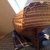
Minor update but mini major milestone as far as I'm concerned. I've finished replanking what I ripped off last August! Only took me 9 months! A loooooooooot longer than I thought but oh so worth it.
So back to finishing the second planking. One band of 9 planks to do. That won't take long right?!?
Thanks for looking
Nick
-
NMBROOK reacted to marktiedens in Royal William by marktiedens - FINISHED - Euromodel - scale 1:72
A little update - lower transom almost finished. I am waiting to see what Chuck at Syren is going to come up with for gun port hinges - the kit hinges are not very good. They seem to be a bit short for the bottom 2 rows of lids. In the mean time I am doing a little treenailing - not any particular pattern,mostly just at the plank ends. Some are actual ends,but most are just scribed on the planks. I didn`t make the lower part of the transom as concave as some others,but I think it looks ok.
Mark
-
 NMBROOK got a reaction from Beef Wellington in HMS Jason by Beef Wellington - Caldercraft - 1:64 - Artois-class frigate modified from HMS Diana 1794
Super crisp work Jason She is looking fantastic
Kind Regards
Nigel
-
 NMBROOK got a reaction from Obormotov in HMS Victory by guraus - scale 1:48 - plank on frame
Alexandru,wow,this has got to be the most spectacular models of Victory I have seen.I am not a big fan of too much paint on my own models,I would rather let the beauty of the timber shine through,so your build appeals to me greatly .
Stunning work!
Kind Regards
Nigel
-
NMBROOK reacted to piratepete007 in HMS Royal William by KeithW - Euromodel - 1/72
Hello All,
Generally I sit in the background watching all these builds of the Royal William with a myriad of variations which are always fascinating. I admire each and every one of them and enjoy the solving of the problems that these variations create. These builds have moved away from the basic kit build - but that so easily happens ! There is an 'invitation' hidden somewhere that invites these changes.
In the meantime, I am making changes to my files as a result of what I see on MSW.
I feel moved to make a comment on one basic point - gun port positioning. The positioning of ports on the gun and main decks is already pre-determined by the supporting blocks but it is the upper ports that need careful alignment so that they fit in with the metal ornamentation. Also the port adjacent to the transom side gallery needs to be cut out after the transom is completed.
In simplistic terms, the gun carriages - already constructed - mounted on the deck surfaces will themselves determine the height of the port. It is the longitudinal positioning that becomes critical to match in with the metal ornamentation.
The problem will always be that some builders take their measurements directly off the drawings which is TOTALLY INCORRECT. The problem comes about due to the inward curvature of the hull that creates a larger measurement than the drawing indicates. The first diagram below (from the Euromodel Resource File for the Falmouth) illustrates this point by comparing a vertically arranged drawing with the actual ship behind it.
The second diagram (thanks to advice from Nigel) illustrates a useful method for determining port positions. Here a vertical marker is used to determine the actual height above the keel, taking the measurements off a vertically arranged drawing. If this does not make sense, send me a PM to save room on Keith's post .
Pete
-
NMBROOK reacted to md1400cs in Wasa by md1400cs - FINISHED - Corel - 1:75
Ferit, BV,
Thanks for your comments. Certainly appreciated. blush (;-) --- Also thanks mates for the "likes" always a pleasure.
PS: Had I walked into this kit today after all that I have learned following other build logs, I would have done things differently with the hull planking as well as with the cannon framings.
Well the two under my table should benefit, i guess..
Regards,
Michael
-
NMBROOK reacted to marsalv in Pandora by marsalv - FINISHED - 1:52
Hi to all,
so after a long break back to "work" .
To Tom - used wood is boxwood and steamed pear
To Nigel - No, I don´t.
To Greg - I had to instal the hanging knees before beams due colloring of inner bulwarks, but I like it.
To aviaamator - sorry for flaws. I agree that real part of deck is little bit simplified because the interior will not be visible.
Sorry for delay with reply.
As another part I chose the production of guns. Guns will be turned from brass, the problem is that turning is a completely new thing for me and so far I'm learning it. I've ruined so much material over and spent so much time that would be cheaper to buy finished guns. On the other side it is the great challange for me. I hope that in a few days I will be able to "show" some result. For now at least I prepared various eyelets and hooks.
-
NMBROOK reacted to marsalv in Pandora by marsalv - FINISHED - 1:52
Hi Daniel, the blue color is acrylic paint from czech producer (http://obchod.agama-model.cz/cz-detail-235034-r29-p-tmava-sedomodra.html).
Aft cabin bulkheads are finished and installed on the deck.
-
NMBROOK reacted to Gaetan Bordeleau in Mills...Spindle Speed
speed and feed work together
you can use a speed of 500 tpm if you want but the feed will need to be slower
20,000 is a more accurate speed because it will leave as smoother finish on a long run
you could probably do molding at a very slow speed but a slow feed would means it would take 10 times longer to do
The idea is to find a middle speed of a motor which will give a reasonable feed
you could go to 50000 tpm for wood or metal but especially with metal, such a speed will throw metal shavings many feet away if you do not stop it
-
NMBROOK reacted to Keith_W in HMS Royal William by KeithW - Euromodel - 1/72
For those who have yet to cut out the gunports, you should take note that the position of some of these gunports is absolutely critical. Not all are.
Ideally, Euromodel should provide pre-cut plywood gunports, like other kit manufacturers. If they don't, they could supply a paper template - but they don't do that either. Instead, they supply plans. Whilst the plans are very good, they are a 2 dimensional representation of a 3 dimensional shape. As a result, the position of any features drawn in the plans which curves away from flat in the real ship can not be trusted.
Furthermore, what most RW builders have done is trace out the plans on tracing paper, then align the tracing paper on the model to cut out the gunports. This is not reliable either. I have multiple gunports which are off by as much as 10mm - in 1/72 scale terms, this is a massive error.
Fortunately, the position of most of these gunports don't matter very much. But a few of these gunports definitely matter, and I would like to draw your attention to them.
1. The position of this gunport should be located at the end of the transom support (Parts 54/55). It abuts, but does not cross Frame 7. Because this gunport does not open, I would suggest that this gunport not be cut out until the transom support is located. Otherwise your transom support might foul the gunport opening. This is not a discovery you want to make when your second planking and wales have already been installed. Fortunately, mine were correctly cut out.
2. This gunport is located immediately under the termination of the poop deck. As other posts have indicated, the length of the Euromodel supplied poop deck is incorrect when compared to the plans. Most of us have shortened the poop deck. If you do this, you will now find that the gun carriage which should be installed in this position will foul the curved staircase that should be installed.
If you have an eye for this kind of detail, I invite you to look at all the pictures of Euromodel RW that you can find. You will see that this is a common mistake - a mistake that I also made. I had to fix my error by re-locating the gunport (install wood blocks, re-cut). Don't do what I did - learn from my mistake!
3. The position of this gunport on the second quarter deck should be exactly one length of metal part 11184/11185. You will see from my above post that I did not realize this. Fortuitiously, on one side of the ship the position of the gunport was exactly correct. On the other side, I was off by 5mm and had to make repairs.
4. If you locate these gunports improperly, you will not be able to install the fenders. I realized this before the second planking went on, and I had to relocate a number of gunports to accomodate the fenders.
The fenders are 3mm wide. I suggest you cut a strip of 3mm wood and check that the position of your intended gunport does not foul the fender before you cut it out.
Take reference from the location of the side entrance. It should abut (but not cross) Frame 1.
5. If you do not take care in the location of this gunport, you will foul the cathead. Do not cut out this gunport until the location of the cathead has been determined.
6 and 7. Neither of these gunports have their position accurately marked in the plans. This part of the ship curves away thus the position can not be trusted. You will note that neither of these gunports can be opened, and the position is strongly influenced by the position of the beakhead railings. I suggest you do not cut out these gunports until you have dry fitted the beakhead railings.
With the rest of the gunports, you can have an error of a few mm and up to 1cm but it won't prevent you from installing any features. These are the only gunports you need to worry about.
-
NMBROOK reacted to Keith_W in HMS Royal William by KeithW - Euromodel - 1/72
Another update.
Having decided to put off the transom for the time being, I am now installing the metal side decoration pieces. The lower limit of the decoration was determined by reading the plans - 1cm above the last wale. I simply took a compass, set it to 9mm, and drew a line exactly parallel to the last wale. I subtracted 1mm because the black line will be hidden under the metal decoration and I wanted some leeway.
Other RW builders will note that the plans call for the side of the hull to cut exactly at the termination of the poop deck. I did not think that this would look very nice so I made sure that I had at least 1mm to play with.
Each metal piece needs to be shaped to conform to the hull, with holes cut out for gunports. Initially I used a Dremel with a cutting wheel, until I found out that a pair of Xuron nippers did a much faster and neater job. It does leave a nipping mark, but this is easily cut off with a scalpel. Oh yes, the metal is soft enough to be carved with a sharp scalpel!
You will also note that the side window (Euromodel part 11260) has been replaced with a scratch built window. This is necessary to let the light from the LED's through. It also looks much better than the Euromodel supplied part.
I have completed side decorations to the area of the fo'c'sle but decided to stop for the time being while I install the beakhead. I fabricated a replacement for the Euromodel supplied part. This is Mk. 1 of the piece - I do not like the look of the archways so I removed them. I will be fabricating another replacement soon.
Pins were soldered to the railings and holes drilled into the hull to accomodate. As you can see, the railings happily sit on the hull without any glue whatsoever.
A cursory examination of the railings tells you how much they need to be bent to fit the beakhead.
... and they need to be bent in three dimensions. Not going to be an easy task.
Having determined the position of the cathead support, I proceeded to cut out a hole for the cathead.
Uh-oh.
As you can see, the cathead will be much too close to the first gun, and this was despite cutting out the gun position exactly as per Euromodel's plans. Here you can see me moving the position of the gunport - glue in a filler block and recut the gunport.
While i'm at it, I also found that I cut the starboard poop deck gunport FIVE MM short compared to port! As a result, the metal decoration does not quite fit. Here you can see the repair - remove the decoration, fill in the defect with a block, then re-install the decoration.
I will have some thoughts on gunport positioning in the next post.
-
 NMBROOK got a reaction from Shipyard sid in HMS Jason by Beef Wellington - Caldercraft - 1:64 - Artois-class frigate modified from HMS Diana 1794
Super crisp work Jason She is looking fantastic
Kind Regards
Nigel
-
 NMBROOK got a reaction from mtaylor in HMS Jason by Beef Wellington - Caldercraft - 1:64 - Artois-class frigate modified from HMS Diana 1794
Super crisp work Jason She is looking fantastic
Kind Regards
Nigel
-
NMBROOK reacted to Beef Wellington in HMS Jason by Beef Wellington - Caldercraft - 1:64 - Artois-class frigate modified from HMS Diana 1794
Cheers guys (Yes Mort, I can only imagine it getting heavier, especially with all the cannons in place as well!). Good news, the fix to the boo-boo turned out just fine. Lesson learned, so will be putting some protection on these delicate areas going forward. Not much to show for time but feel I need to get up to date. Lots of sanding sessions to get a nice shape, and the weather hasn't really been cooperating.
Batten at the waterline has been installed. Tried thinning down some 1x1mm strip to approx. .5mm thickness but found that this was just too delicate a procedure, so thinned as much as possible and it was pretty easy to take more off once installed. Used PVA to attach which worked just fine as it develops a sufficient tack needed for this thin stuff, even in the curved areas which just required a few minutes of finger pressure. To help with this, I temporarily attached some scrap walnut strip to act as guides.
Once in place, put on a single coat of wipe on poly to protect the surface and then used some walnut stain to colour below the batten. Although this will be coppered, think its better to have a darker surface in case there are gaps between the plates.
Also started to put in place the oar and vent ports. Each needs to be individually shaped as I think it would follow the profile of the other planking. Getting a uniform (or as best I can) fit takes a bit of fiddling. Captain Sterling is keeping on top of things in his new nice new uniform....
And where things stand...
-
NMBROOK reacted to md1400cs in Wasa by md1400cs - FINISHED - Corel - 1:75
Ferit: Thanks for always dropping by and posting encouraging words. I have to assume, as also with most builders, the last bits will be the flags.
Edwin : appreciate your visits and thoughts - Thanks
=======================
Working on rebuilding the mainmast lower platform. The one that I had started pre-building (same size as the foremast one) turns out is a bit too small. This one is easier, having struggled through the first two; now have a better grasp on how to make the small bits at a faster clip
MIchael
-
NMBROOK reacted to EJ_L in La Couronne by EJ_L - FINISHED - Corel - 1:100 - 1637 Version
I got the forward bulkhead planked and finished the hull where it wraps around the bow. I still think this was a very impractical design with the gun placement but it does have an interesting look instead of just a flat, blunt front. The weather also cooperated and the rain held which was great as I hate trying to apply finish to wood with high humidity as it takes much longer for it to dry between coats. This allowed me to get the finish applied and I think she looks great now with the wood colors brought out. Although there are a few flaws this is my best planking job I've done.
I have removed the temporary decks down to the upper gun deck and I will now begin to plank the interior bulkheads and detail it out. I will also begin the long process of building all the canons. This is where the excitement of seeing all the tiny details take shape begins.
-
NMBROOK reacted to rafine in Granado by rafine - FINISHED - Caldercraft - 1:64
I've completed the first planking of the lower hull on the port side. My intention was to do it "quick and dirty" , so as to achieve a smooth, flowing surface for the second planking, without worrying too much about a prototypical planking pattern. My reaction after doing this work is to wonder why anyone would want to bother with double planking a hull. It seems like an awful lot of extra work. I'm still going to have to do all of the lay-out work for the final planking that I would have done if it were single planked.
In any event, it's now on to the starboard side.
Bob
-
NMBROOK reacted to md1400cs in Wasa by md1400cs - FINISHED - Corel - 1:75
Hi mates,
So lower mainmast is now completed. Here are some updated pics.
Now onto re-building a lower top for the main – need to order some rope from Chuck so shrouds pending.
Again – as always - thanks for the comments, the Likes and/or just dropping in for a visit.
PS: Nigel your pencil suggestion made such a great diff. Thanks again.
Cheers,
Michael
-
NMBROOK reacted to donrobinson in Trabakul by donrobinson - FINISHED - MarisStella - 1:32 scale
Well I think this hobby has gotten the best of me, I mean who wakes up in the morning excited about making filler blocks? It's just not right .
Before I jumped into this madness I did manage to get some of the outside work done so maybe I'm not totally over the edge yet.
For the blocks I cut some pieces out of a 1x6 board to size then shaped by cutting one edge on scroll, and shaped the rest on the belt/disc sander. Finished shaping by hand then glued in place. In the pictures only the starboard stern side has been slightly faired I am leaving the rest of the fairing until I finish with installing all the filler blocks. I'm thinking that all in all I probably spent about 4-5 hours making and installing them.
Stern filler block
Bow filler block
Bow
Stern
Have a good night
-
NMBROOK reacted to marktiedens in Royal William by marktiedens - FINISHED - Euromodel - scale 1:72
Hi all - I thought I would take a little break from that nasty transom & work on the rudder. The laser cut rudder supplied in the kit has the front edge straight with no cut outs for the hinges - forgot to take picture . The thickness of the hinges seemed to make the rudder sit too far away from the post,so I cut out the parts of the rudder where the hinges fasten to inset them. After bending the hinges to fit around the curves of the hull I painted them black & glued them all in place. I decided to go ahead & mount the rudder before installing the transom support - much easier. The rudder is glued in place,but if it were to turn the rounded front edge would keep it from binding against the post. Now back to the transom..........
Mark
-
NMBROOK reacted to Heinz6672 in HMS Victory by Heinz746 - Caldercraft
Thank you so much, Nigel. Your compliment is very welcome !!!
Ian, please don´t let us wait too long for your surprise. I could not wait to see what you are talking about...
Thanks for all your "likes"!!!
Best
-Heinz-
-
 NMBROOK got a reaction from Seventynet in HMS Victory by Heinz746 - Caldercraft
Fabulous work Heinz!
Kind Regards
Nigel
-
 NMBROOK got a reaction from Heinz6672 in HMS Victory by Heinz746 - Caldercraft
Fabulous work Heinz!
Kind Regards
Nigel
-
NMBROOK reacted to modelshipwright in Sovereign of the Seas 1637 by modelshipwright (Bill Short) - Sergal - 1:78 - Port "as built", Starboard "as presented to King Charles I for approval"
Thanks to everyone who dropped by.
Well, after gun surround #4 found the scrap bin as it broke in two, I spent yesterday planking the side panel for the beak on the port side in preparation for mounting after the bulkhead ornamentation is completed. I carved a new surround this morning and it thankfully survived the process in one piece.
Here it is mounted on the bulkhead and the set of four is now complete.
More to follow...............