KeithAug
-
Posts
3,980 -
Joined
-
Last visited
Content Type
Profiles
Forums
Gallery
Events
Everything posted by KeithAug
-
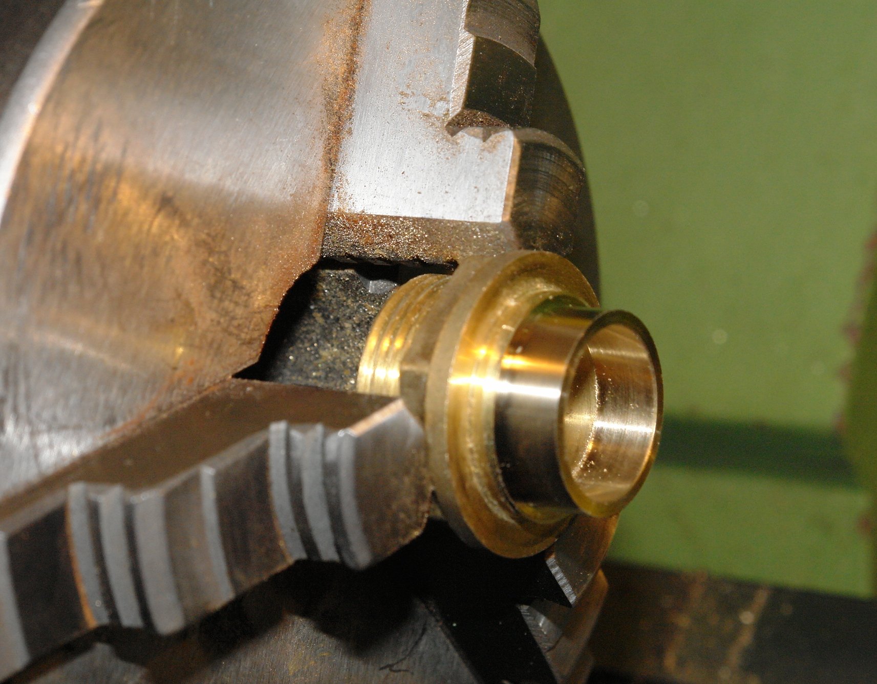
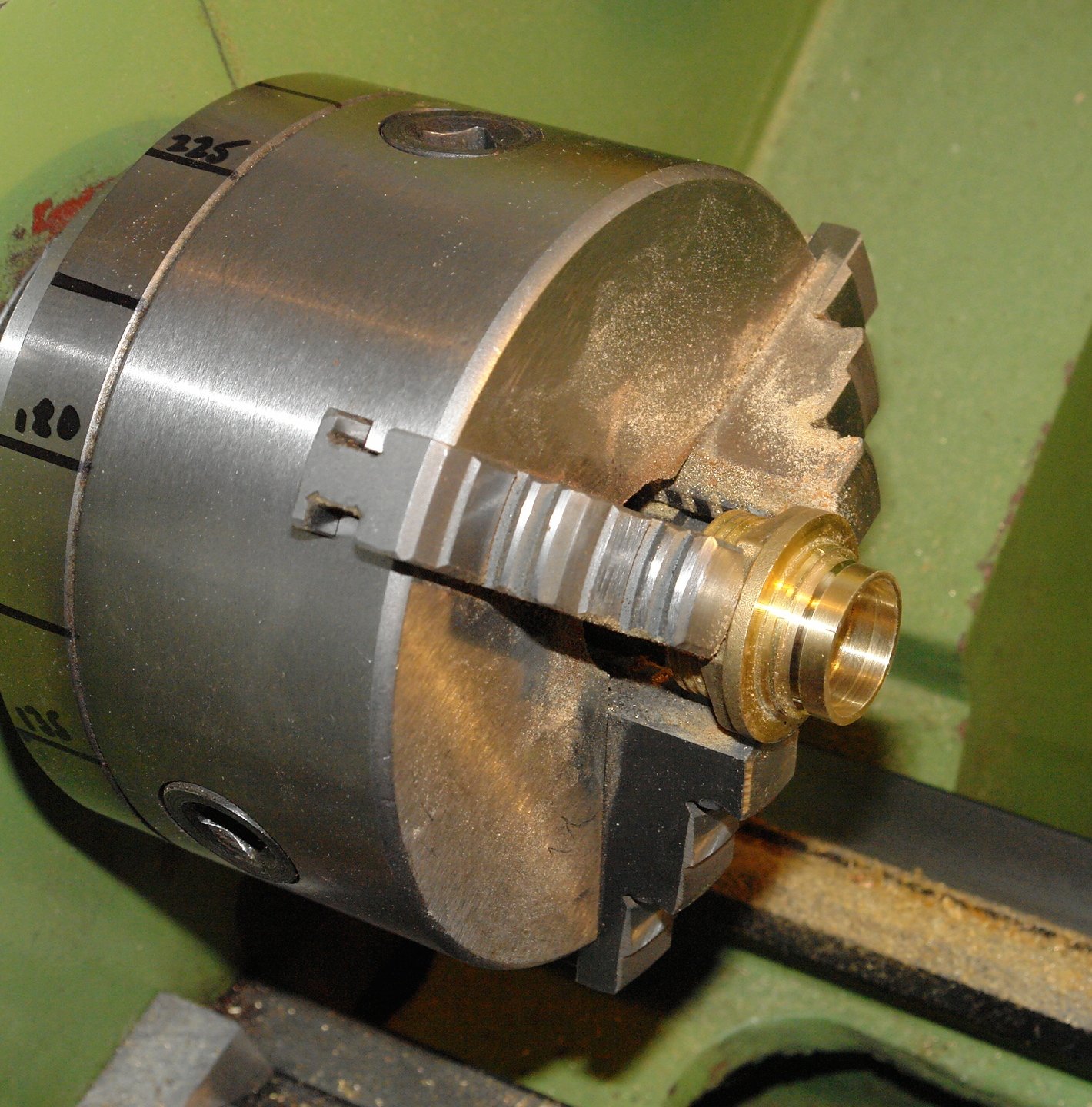
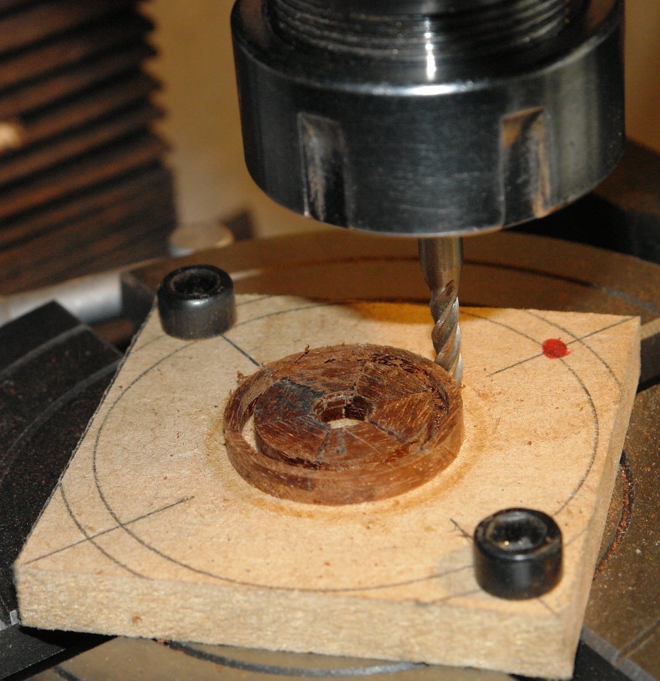
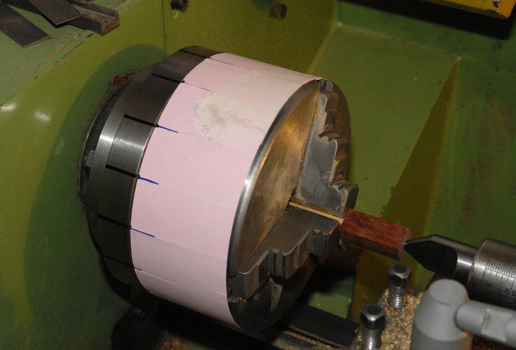
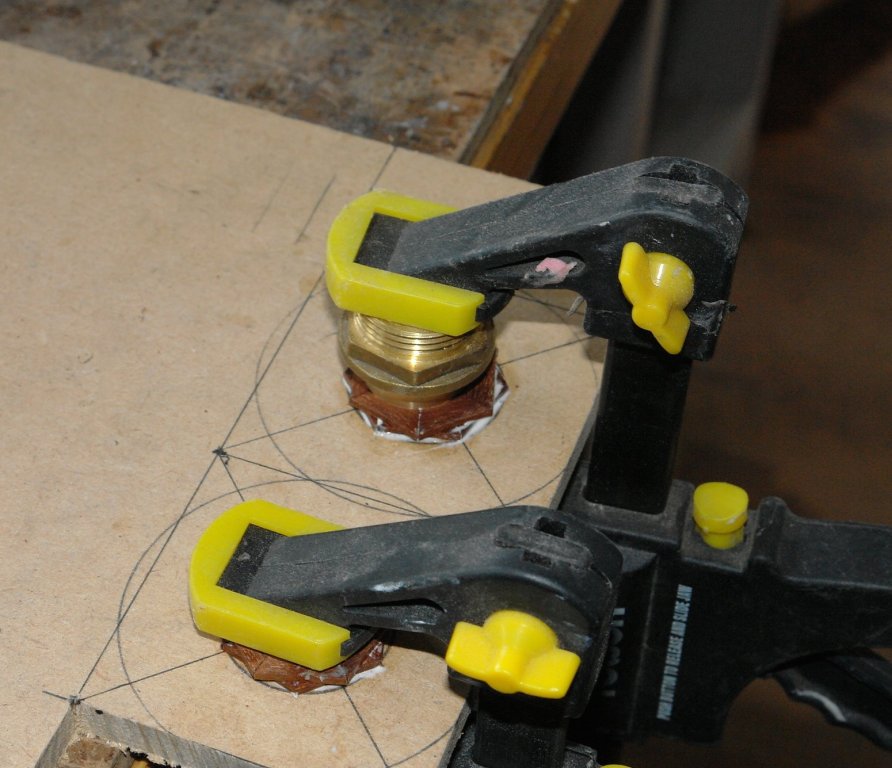
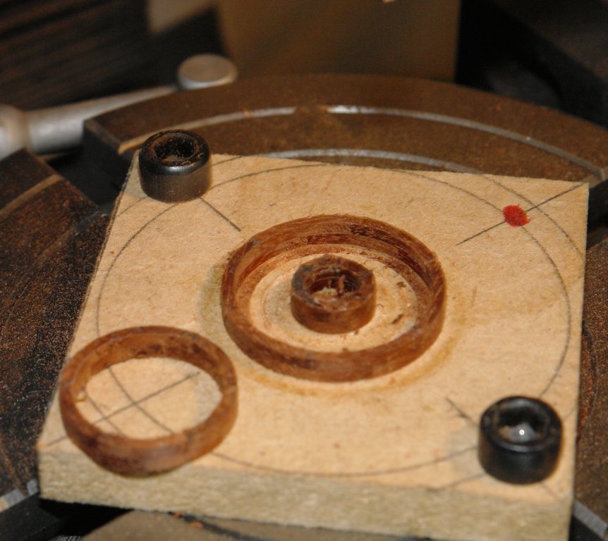
 Continuing with the wheel experiment. Rather than trying to attach the brass rim strip to either side of the rim I decided to "clad" the inner and outer diameters of a brass tube with wood. The result looks identical to that intended and has the advantage of creating a very strong rim which is beneficial for further machining. Unfortunately I didn't have brass rod or tube of the diameter needed. However a bit of searching through the DIY plumbing box produced a connector that could be machined to size. I machined a groove to ease later parting off of the rim. I needed to lay up a further couple of hoops to clad the bore and outside of the brass ring. The hoops were then machined out as per the last post. At this stage I left the hoops over thick (.080 inch). This is twice the finished thickness. I was a bit worried that making thinner hoops would lead to their collapse. In hindsight I could have gone thiner, witnessed by one hoop which was produced as a by product and maintained its integrity with a wall thickness of only .017 inch. The rim here looks very heavy because the wooden hoops are twice the desired thickness. Here is the very thin hoop. The final part of this stage was to attach the hoops to the brass tube with CA glue prior to a bit of light wet and dry sanding of the face. Both rims are ready to have the 8 radial holes drilled to take the spokes.


-
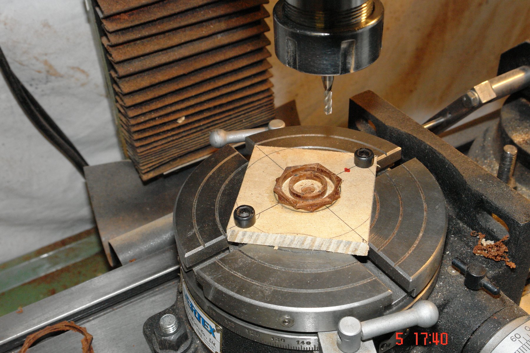
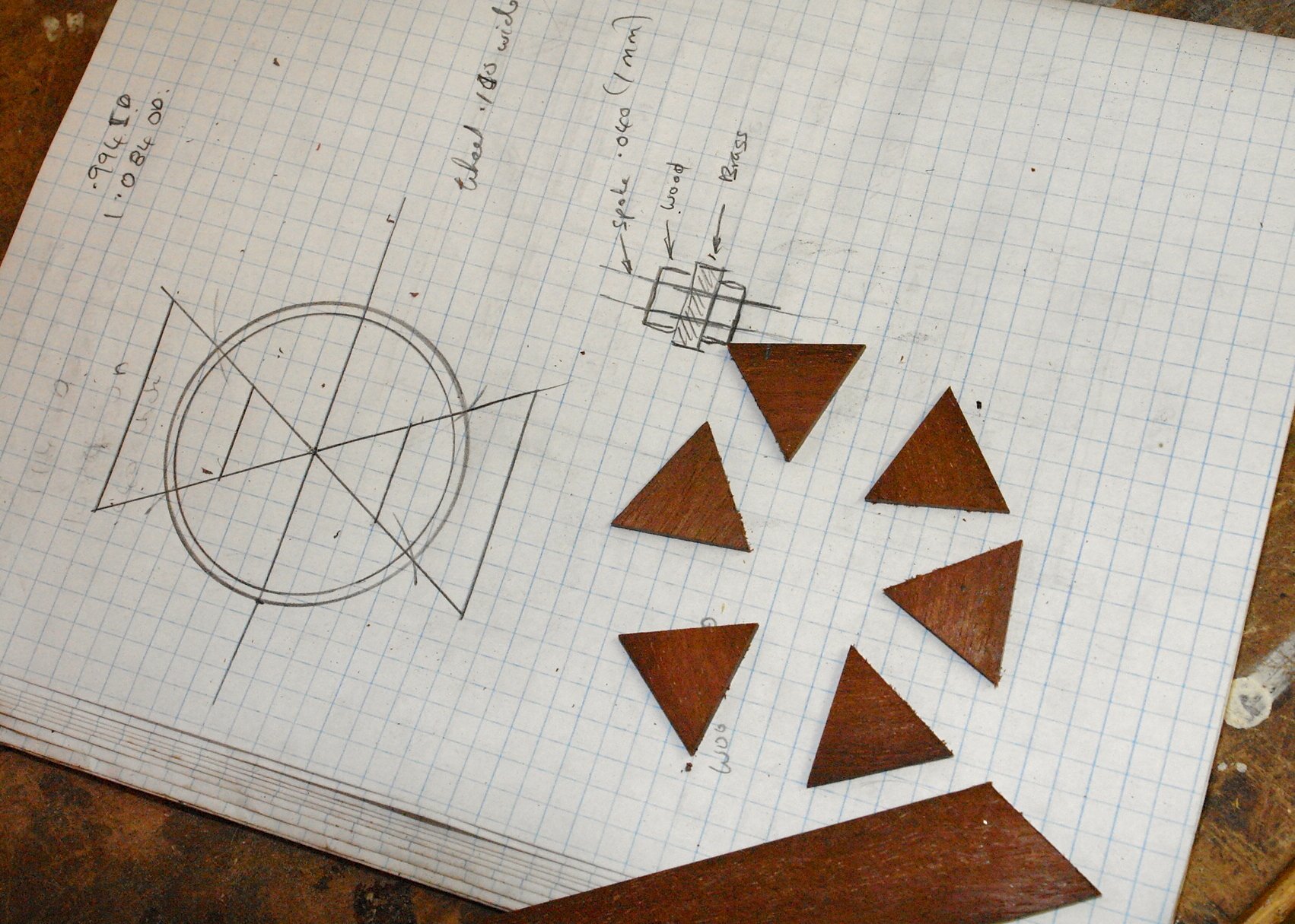
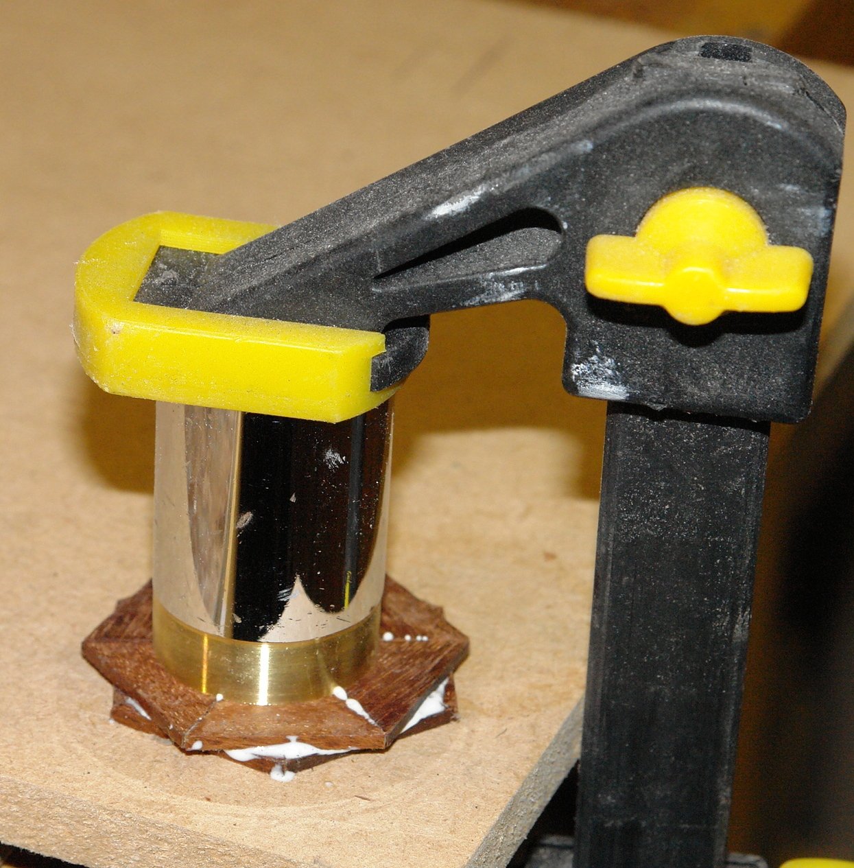
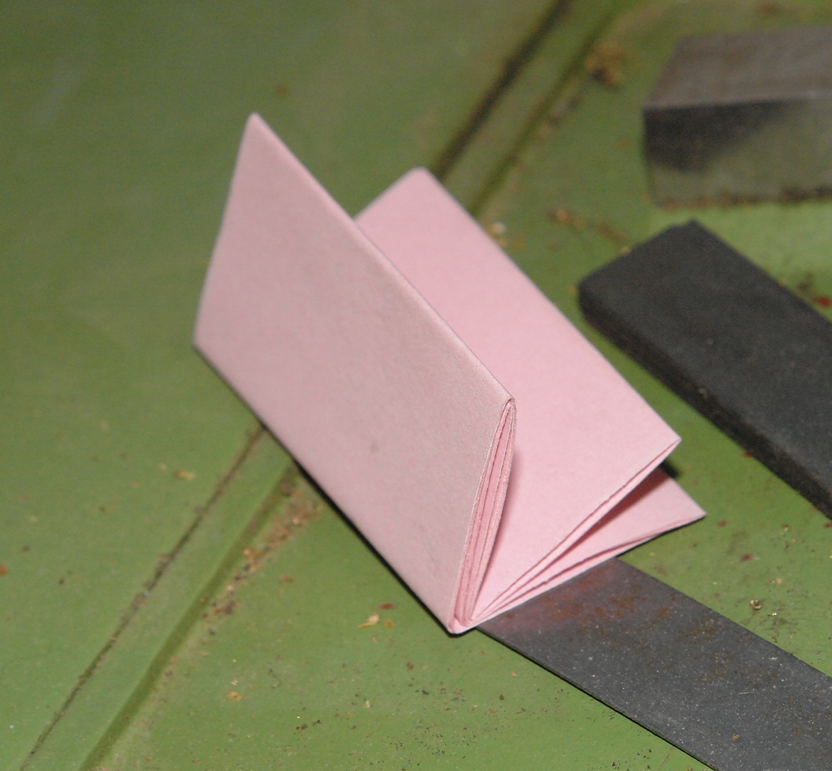
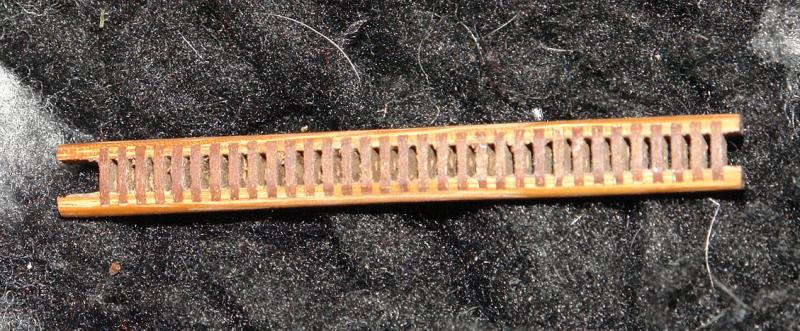
I started the wheel experiments. I decided to build 2 versions and see how they turned out. Altair's wheel has a solid brass band set into the front and rear face of the rim. Its quite a nice feature and I am wondering whether I can reproduce it without the wheel looking too heavy. The second version is a back up, without the brass band. This is a somewhat simpler and more streamlined design. The diameter at the rim is just under 1 inch and this introduces some challenges. Anyway to make a start:- Making the rim by turning a dowel to the outside diameter and then boring out the inside didn't appeal as I considered the grain direction would make hoop too fragile. I felt the grain needed to follow round the rim and this meant fabricating the rim from a number of section. This in turn could have introduced joint weaknesses but these were overcome by making the rim out of 2 layers with the 2nd layer rotated to stagger the joints. The photos probably explain this better. The assembly is glued on to a MDF backing to facilitate later machining. I gave cutting the rim hoop a bit of thought. The obvious solution was the lathe but I was concerned that the forces be too great and the hoop would break during machining. I felt milling would be a less harsh process and this proved to be the case. The middle sized hoop is the one I need for the simple version of the wheel. The large and small hoops are a bonus of the process. The hoop was then mounted on a spigot ready for drilling radial holes to take the spokes prior to final shaping. Ill cover progress on the more complicated wheel in my next post.


- 882 replies
-
- 11
-

-
Dear John Thank you for the good advice. It arrived while my better half was out. It is now in a corner of the workshop unpacked but in full view. My wife paid a visit this morning to inspect boat construction progress. She had been to an auction yesterday and in passing looked at a Bassett Lowke pond yacht. She was comparing quality and pronounced my attempt was better. The distraction was enough and she departed without recognising the new asset. Her visits to the workshop are infrequent, one benefit of having no heating. I don't expect another visit for several months by which time a layer of dust may well help disguise the addition. All I have to do now is intercept the bank statement. Alternatively I could just own up. We have only been married 42 years so I am still learning. I bow to your additional 6 years of experience, such expertise is of significant value to NRG. Have you considered starting a marital help line thread? I am now off to cook the evening meal - curry with all the trimmings. Perhaps I could tell her over a papadum!
-
Michael/Mark/Greg Thank you for your comments. I spent yesterday experimenting with wheel making (the rim). Not quite got it cracked yet but I may post details of the experiments later. I find I learn more when I experiment but it does slow progress. Also thank you all of you who have hit the like button.
-
Hello George I'm very encouraged to hear that handcrafts remain of interest in the modern world of virtual reality. Good luck with the build.
-
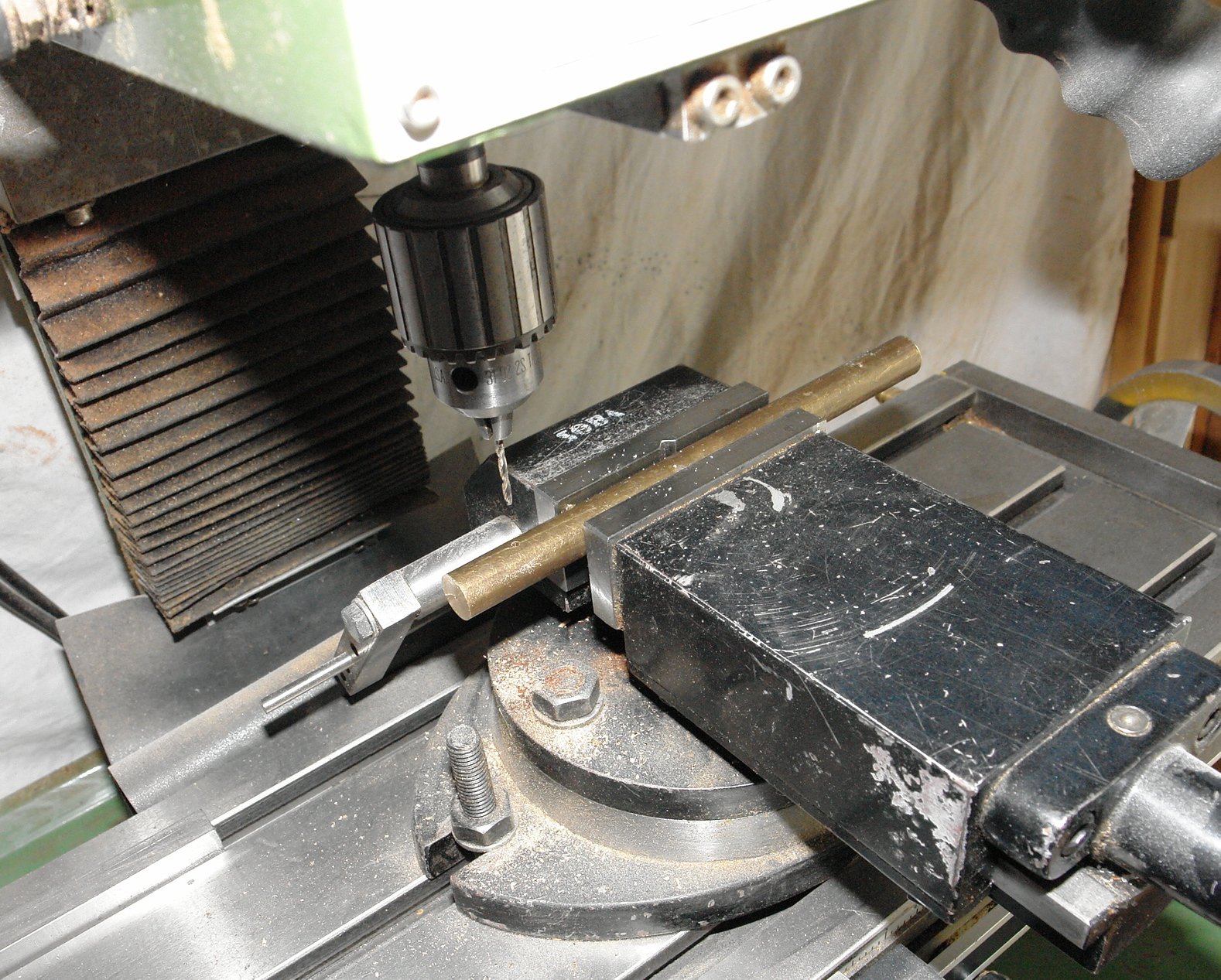
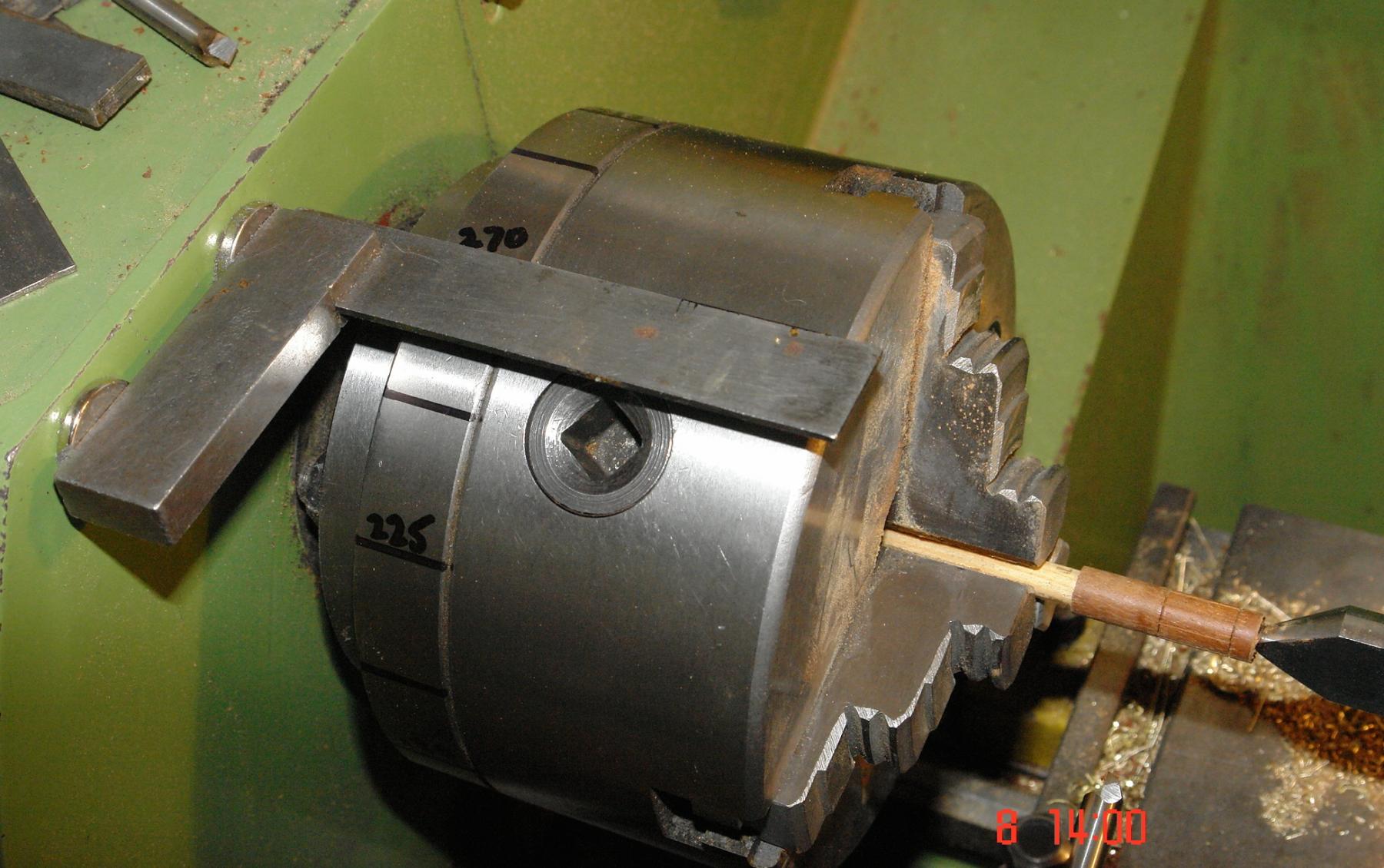
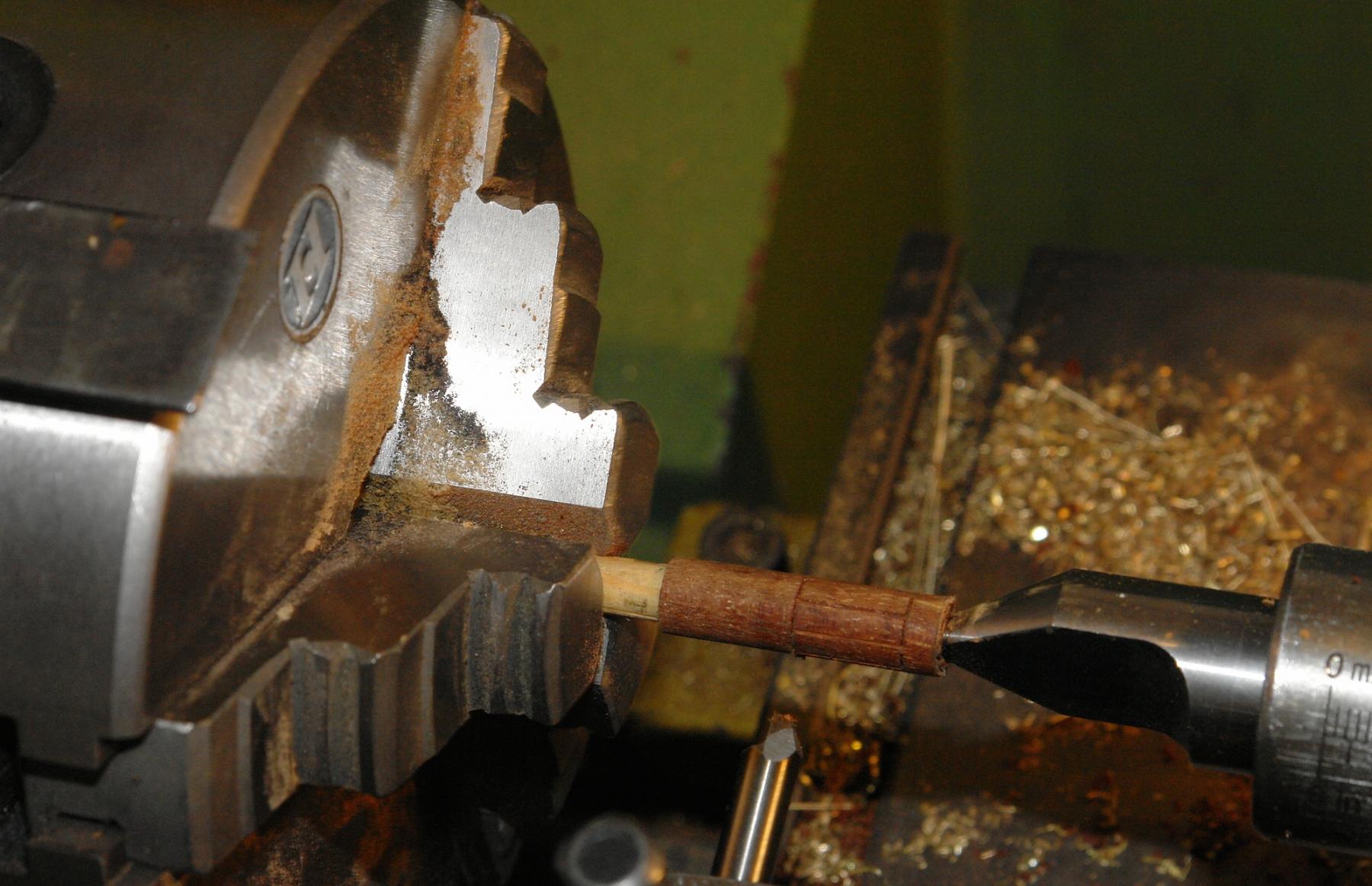
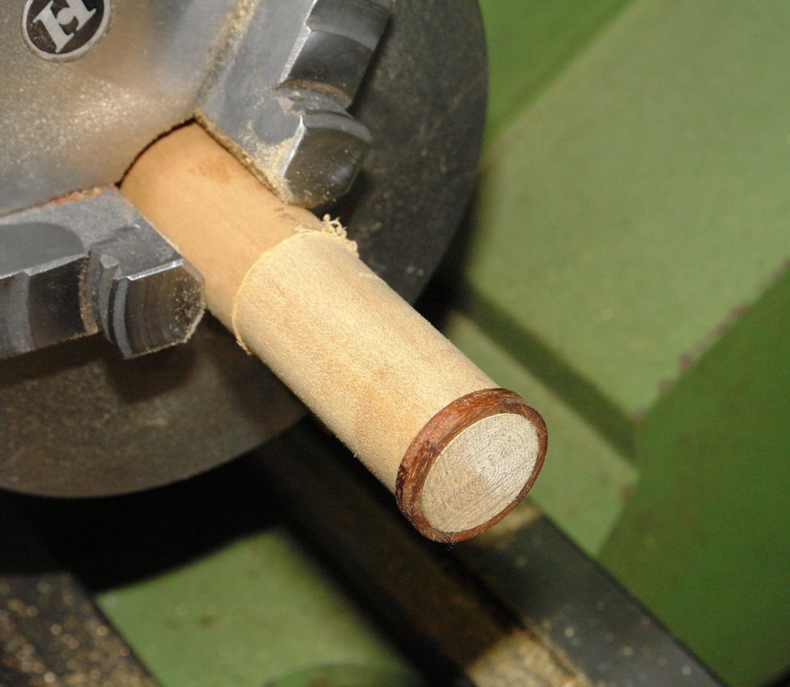
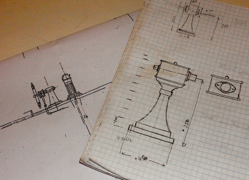
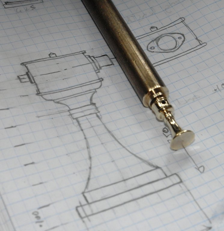
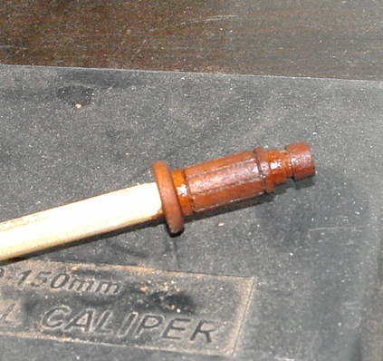
Thank you Per. Today I celebrated the completion of decorating by doing a little turning. Altair has a very nice brass wheel pedestal which the plans do not do justice to - the plan is on the left and my drawing on the right is created from photographs using the basic dimensions from the plan. The pedestal is turned from 0.5" bar. The first operation was to drill the .075" hole to take the hub of the wheel. The turning was complicated by the need to create the sweeping curve at the lower end. I couldn't be bothered to mount the ball turning tool so I formed the curve by rotating the saddle and cross slide wheels in unison. A bit tricky but it worked ok. The pedestal height is 0.85". Now I need to face up to making the wheel. I may take a while!!!!

- 882 replies
-
- 14
-
-
Hello Michael I thought lot 939 might be of passing interest. http://www.bellmans.co.uk/sales/sussex-antiques-sales/mar2017/?page=10
- 749 replies
-
- 4
-
-
- albertic
- ocean liner
- (and 2 more)
-
Hello Phil Looking forward to the build log. Keith
-
ancre La Salamandre by tadheus - 1:24
KeithAug replied to tadheus's topic in - Build logs for subjects built 1751 - 1800
Hello Pawel She continues to look great, nice little plane. -
The dolls house plan may not work. She has one I built for my daughter 30 years ago. However you may be on to something. She is a jigsaw fan so maybe that can be a first project for the scroll saw.
-
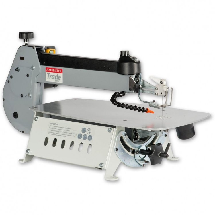
I thought I should update even though I am banned from the workshop until the decoration of the lounge and dining room is finished. Optimistically this is scheduled for a week today. In the meantime I took time out to order an Excalibur 21 inch throat scroll saw. I need a plan for broaching this with my wife before the delivery van arrives. Oh hum!
-
Michael Is making it better than the original allowed?????
- 749 replies
-
- 3
-
-
- albertic
- ocean liner
- (and 2 more)
-
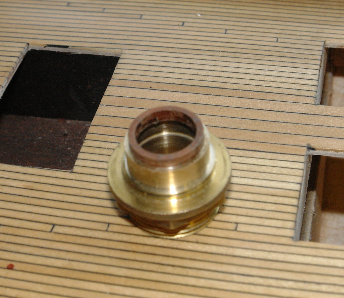
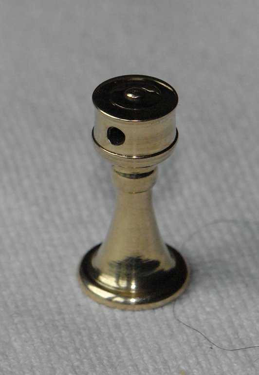
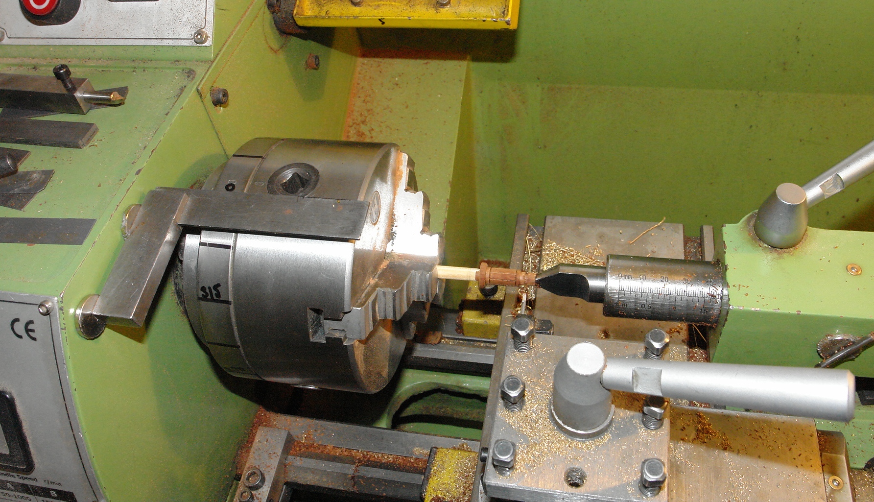
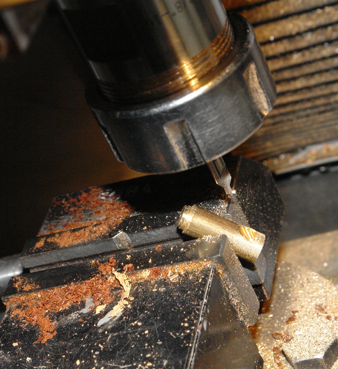
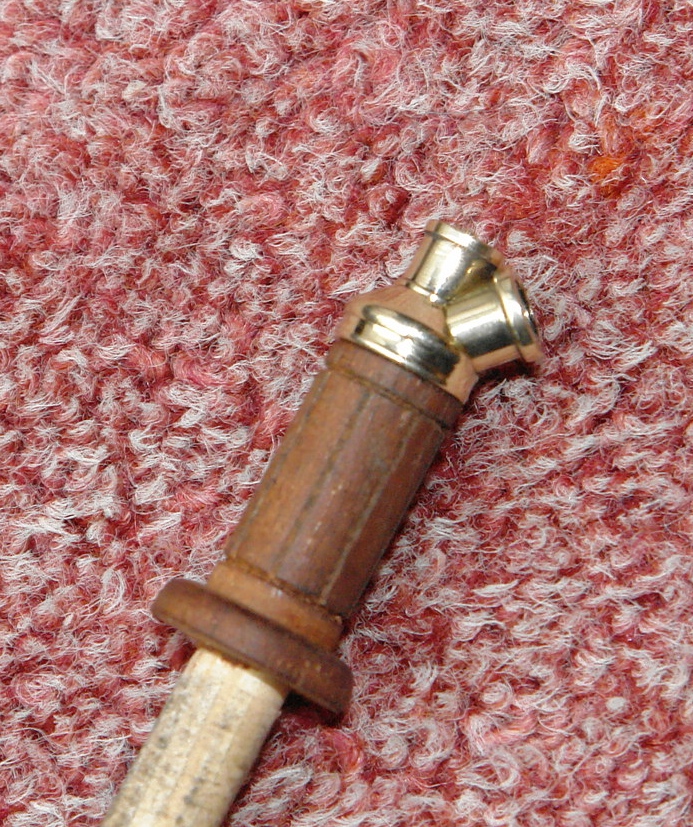
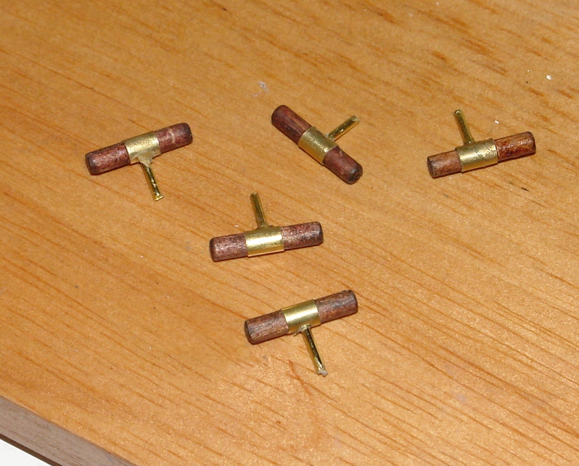
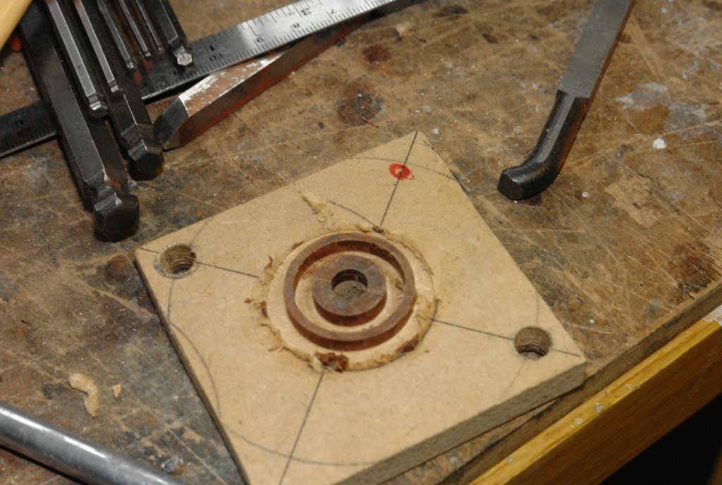
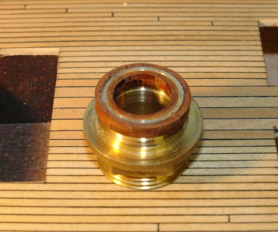
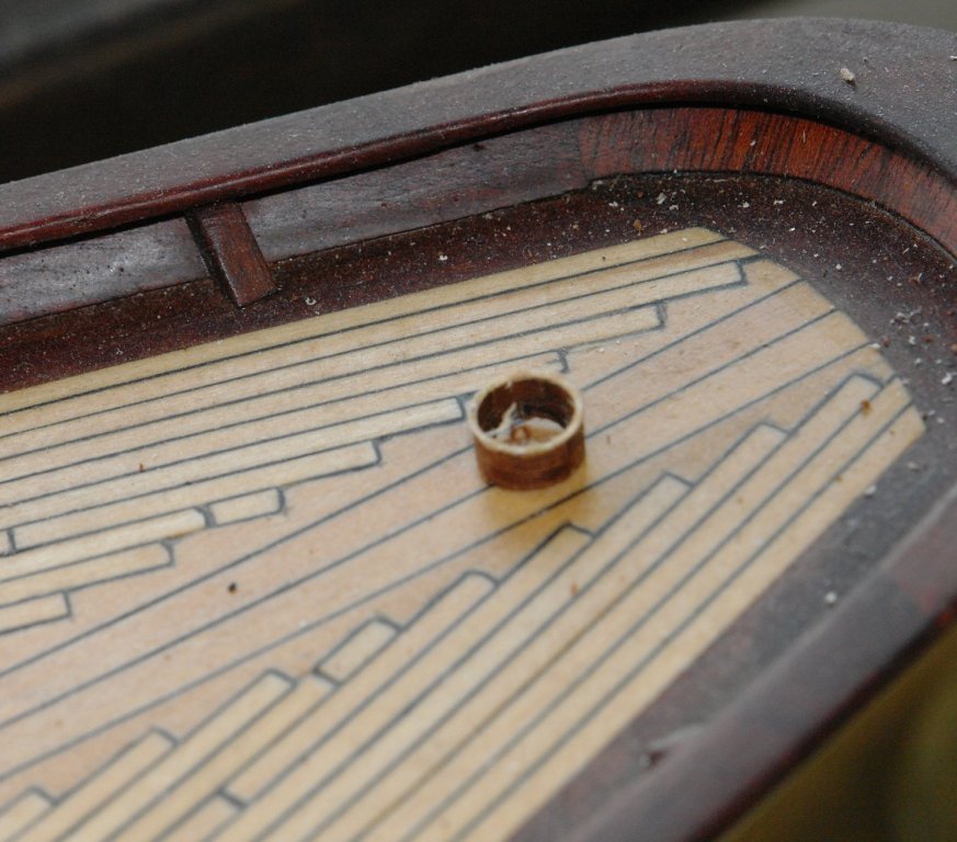
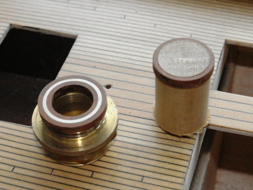
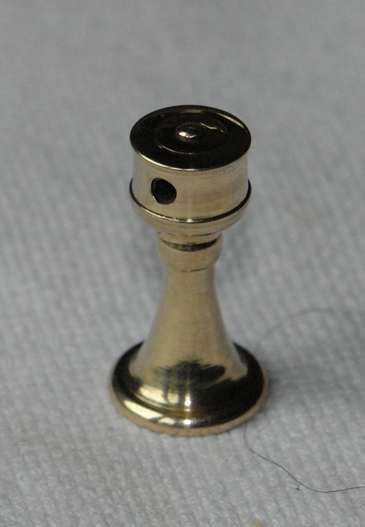
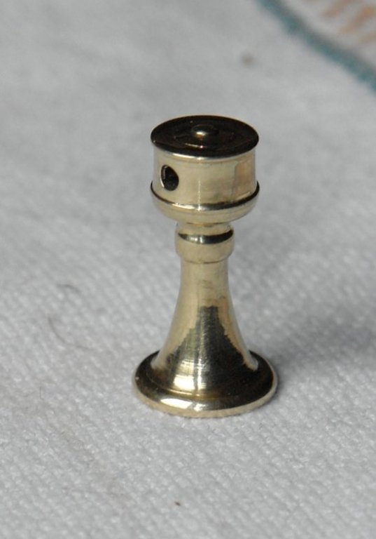
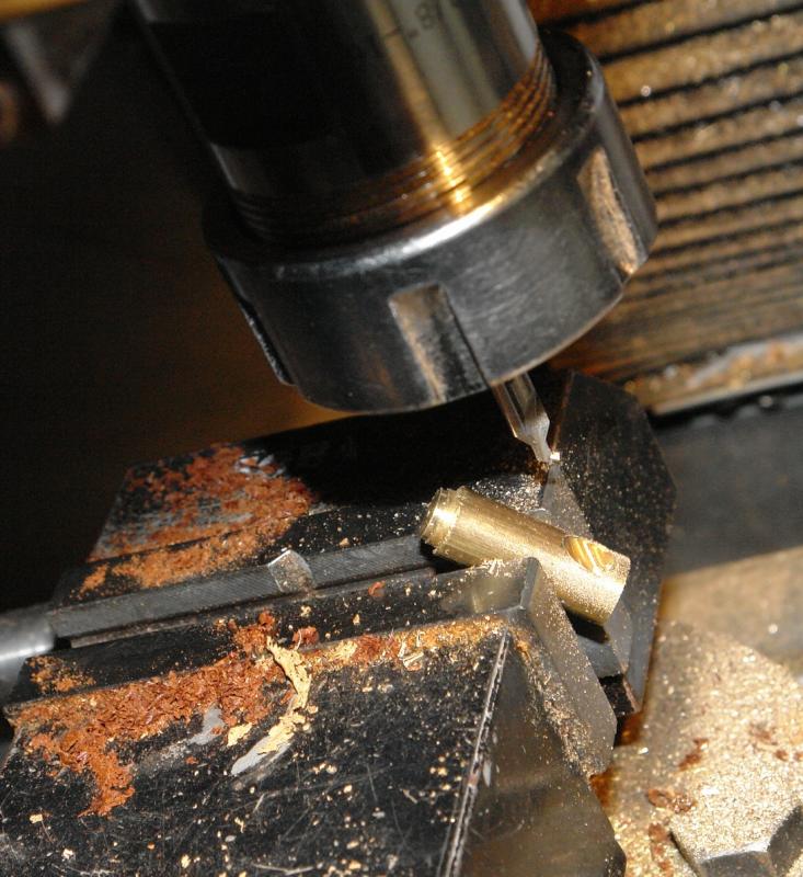
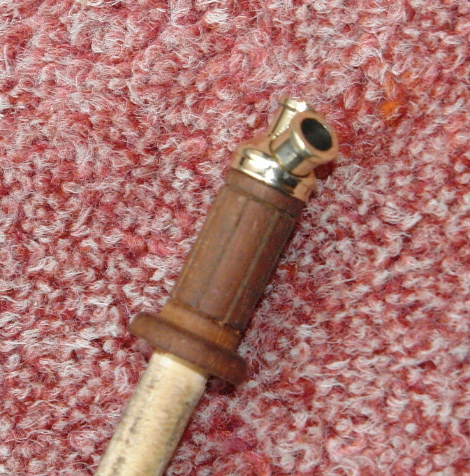
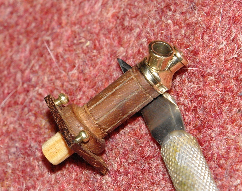
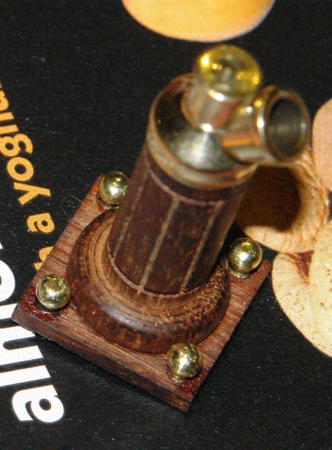
Binnacle 2nd attempt:- The body was made as previously explained. This time I reversed the direction in the chuck and cut the circular plinth as part of the main body. Previously the plinth had been made separately and this introduced the weakness that led to the chip. The conical cover was made from bar and the first operation was milling the flat and then drilling the hole for mounting the viewing tube / window. The conical form was then machined on the lathe. Likewise the viewing tube was turned up from bar and the two parts were glued together with CA. The cover was then glued to the stem again with CA. The bottom square plinth was cut from mahogany and drilled with a central mounting hole and 4 peripheral holes to take the brass balls. The balls were made using "Michaels stanchion method".


-
Hello Bob The frames look excellent. Very neat given the scale at which you are working.
-
Hi Michael. Many years ago I spent part of my apprenticeship in the Rolls Royce Ltd draughting training school and I remember the line dividing method from there. It was however in the dark ages before CAD and has faded in my memory. Your prompt is well made.
-
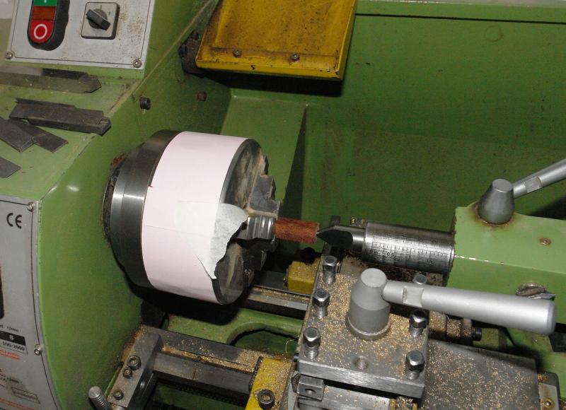
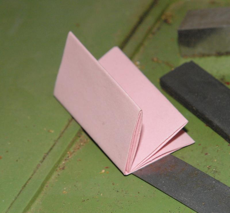
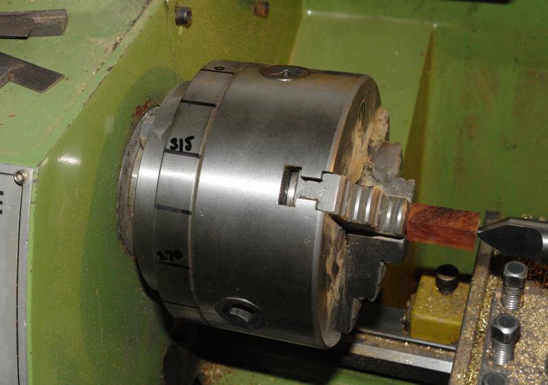
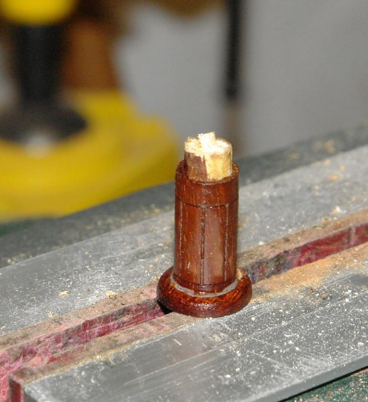
Bedford - you may be right. At the moment I'm still in block avoidance mode - so as a distraction I made the compass binnacle. This may be a bit of a long post and depending on the call for dinner it is likely to be a tail of two halves. Altairs binnacle has a stem of mahogany which has detail of longitudinal panels. This sits on a plinth with brass ball details at each corner. Atop the stem sits a removable conical cover with a viewing tube set at an angle. The whole thing is about an inch in height with a stem diameter of 0.3 inch. Turning the stem was straightforward but I wanted to machine axial slots to represent the panel detail. To get the spacing on the lathe required a bit of improvisation with a sheet of paper. The paper was wrapped around the chuck to get the circumference and then folded in half 3 times to give 45 deg increments. This was then used to mark increments on the chuck. The engineers square was held on the headstock with magnets to create the reference. The axial slots were "planed" by traversing the saddle. Unfortunately I ended up with a very small chip in the base, just visible on the right - so this one was thrown away.


-
Michael the walls are mahogany from the old table I have been recycling. The top and base are from antique block floor tiles which I although they have a paler pink tinge I think are still mahogany.
-
Julie The shaping of the assembly only took about 10 minutes. Sanding the individual block took about the same time once it was parted off. Thanks to everyone who hit the like button.
-
John Thank you. I think I am going to have to intersperse block making with other tasks, I can't face up to the prospect of banging them all out one after the other. Much too tedious. I haven't counted up how many I need lest it drives me to despair. I will save the count for when I am in a good mood.
-
ancre La Salamandre by tadheus - 1:24
KeithAug replied to tadheus's topic in - Build logs for subjects built 1751 - 1800
Pawel They all look very good. Keith -
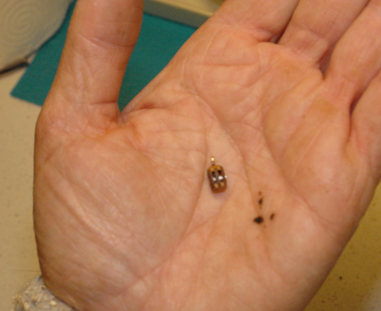
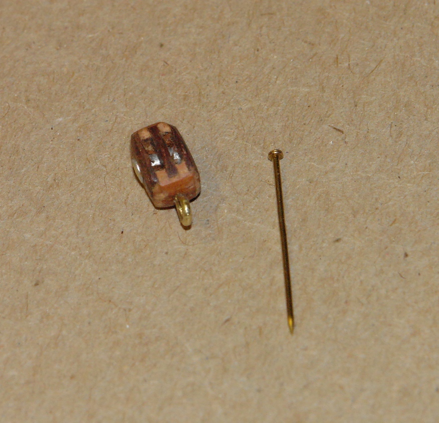
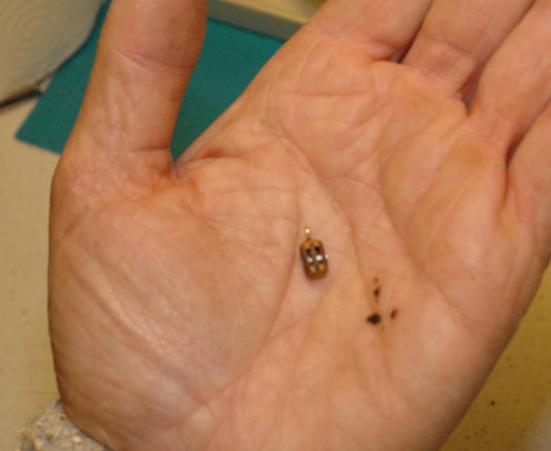
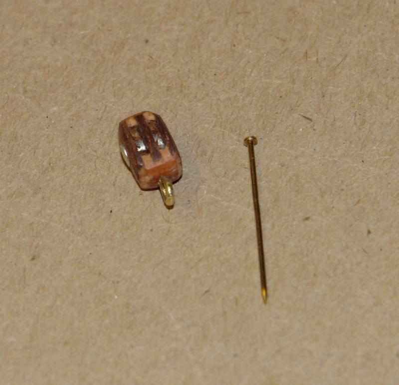
Today I spent much of the time cutting 3" x 2" x 8 foot lengths of timber to repair the lounge floor. As a reward I finished a 2 pulley block. In terms of size it was a case of the ridiculous to the sublime!!!!! The pin is a standard 20mm dressmakers pin.
- 882 replies
-
- 11
-
-
ancre La Salamandre by tadheus - 1:24
KeithAug replied to tadheus's topic in - Build logs for subjects built 1751 - 1800
Pawel What are the barrels made from, they look like metal but the white one suggests something else? -
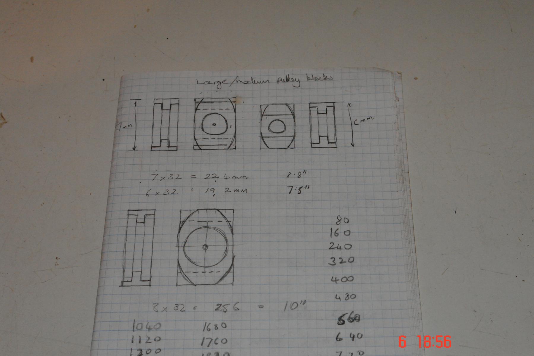
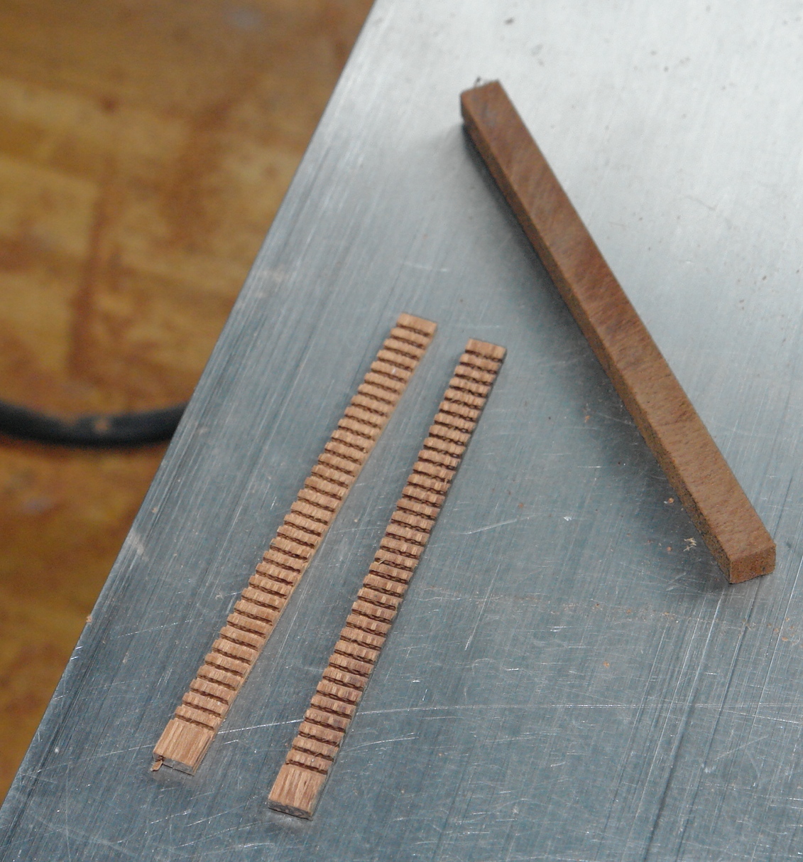
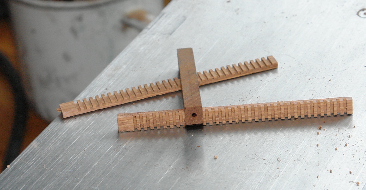
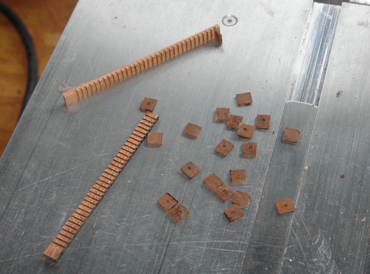
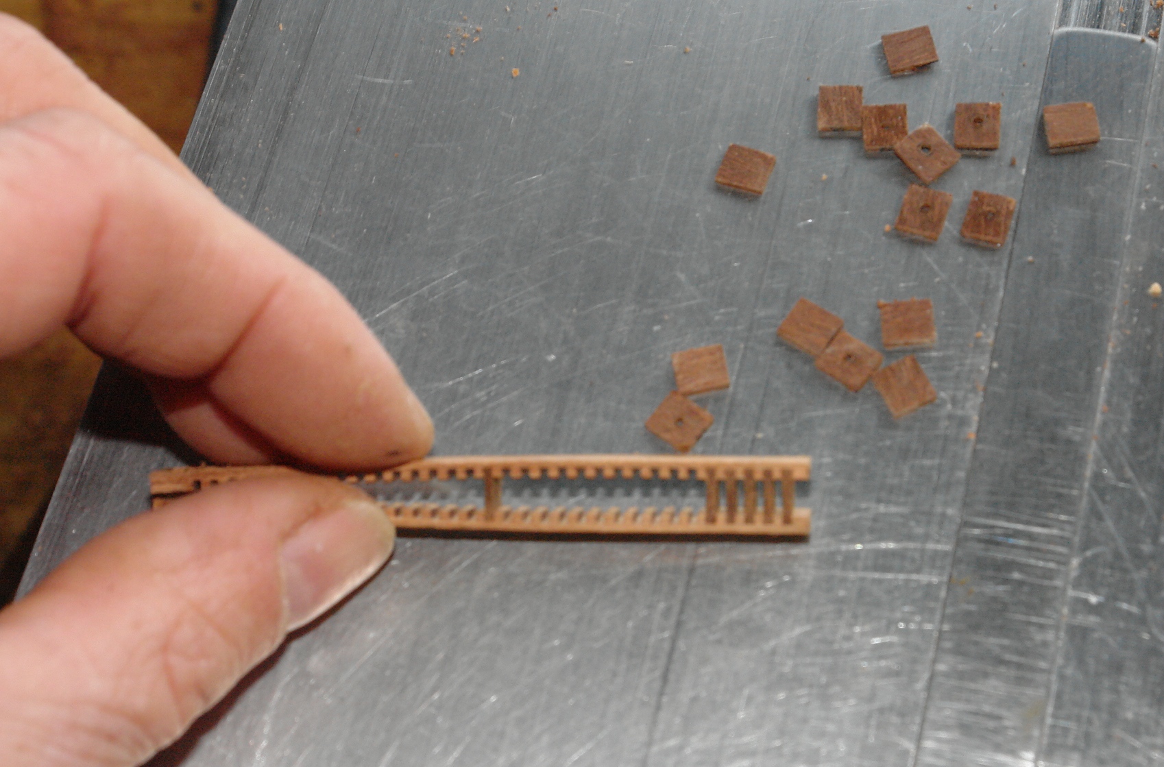
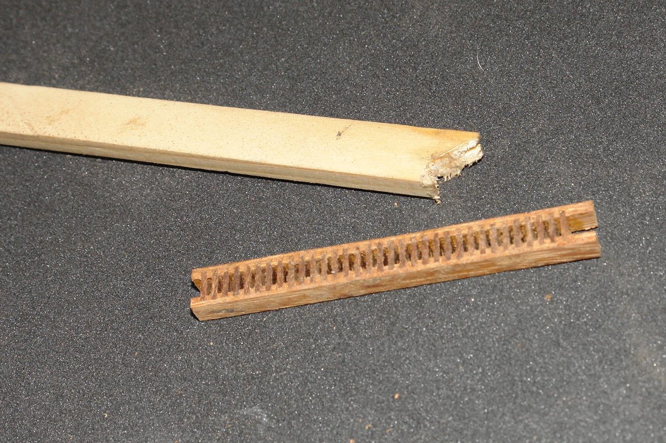
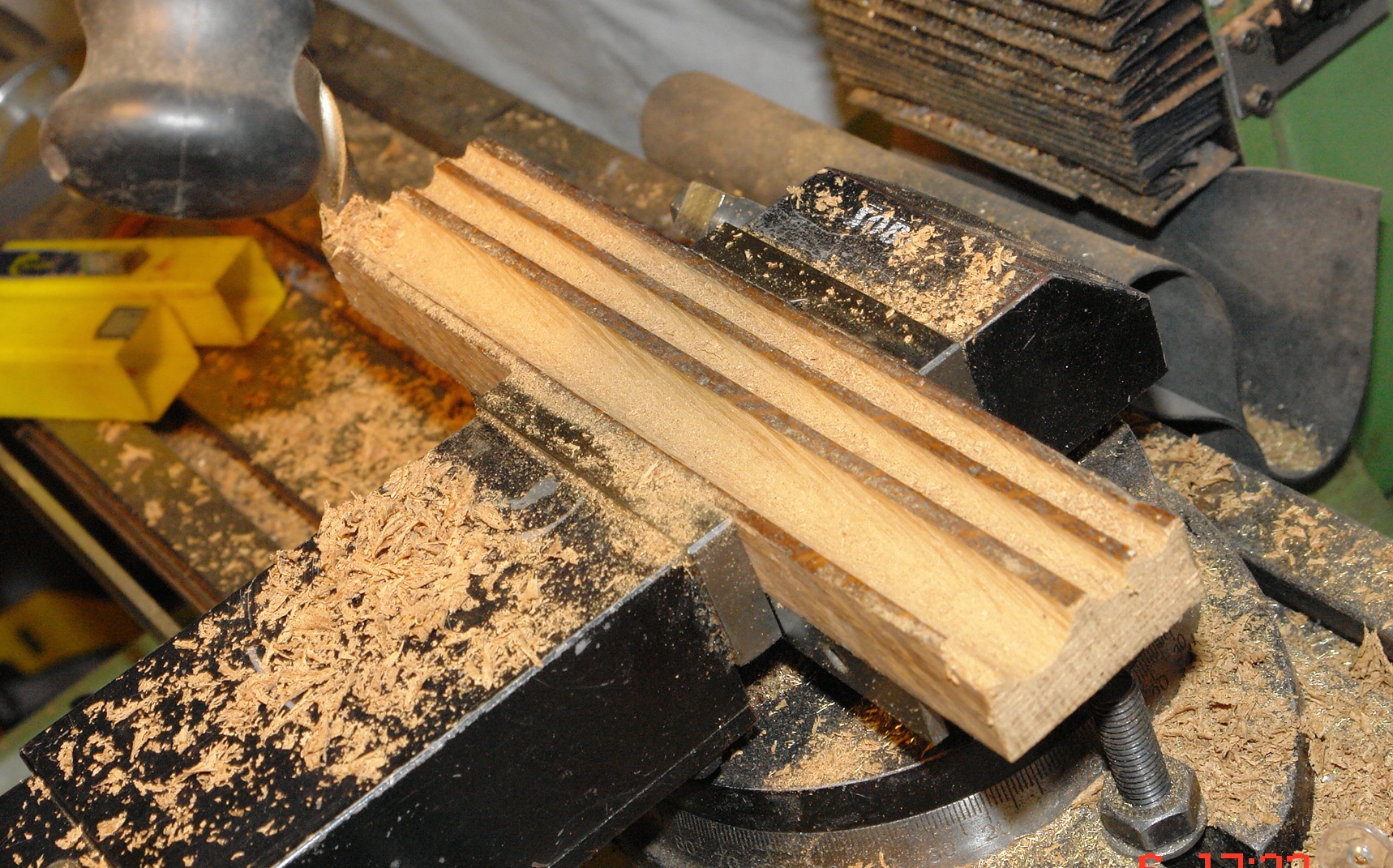
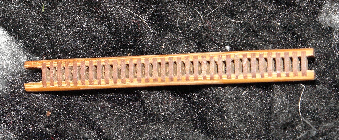
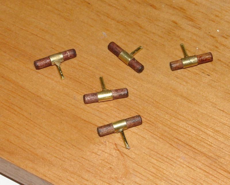
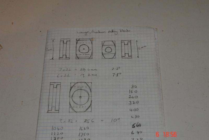
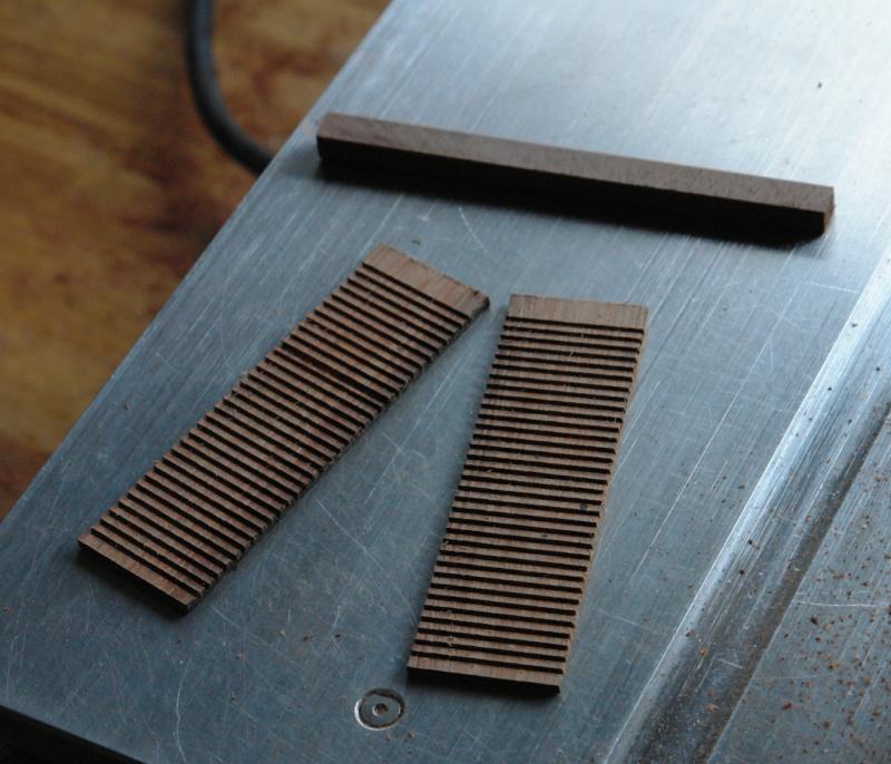
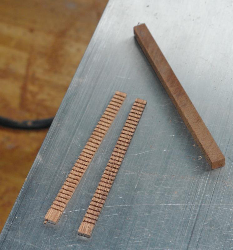
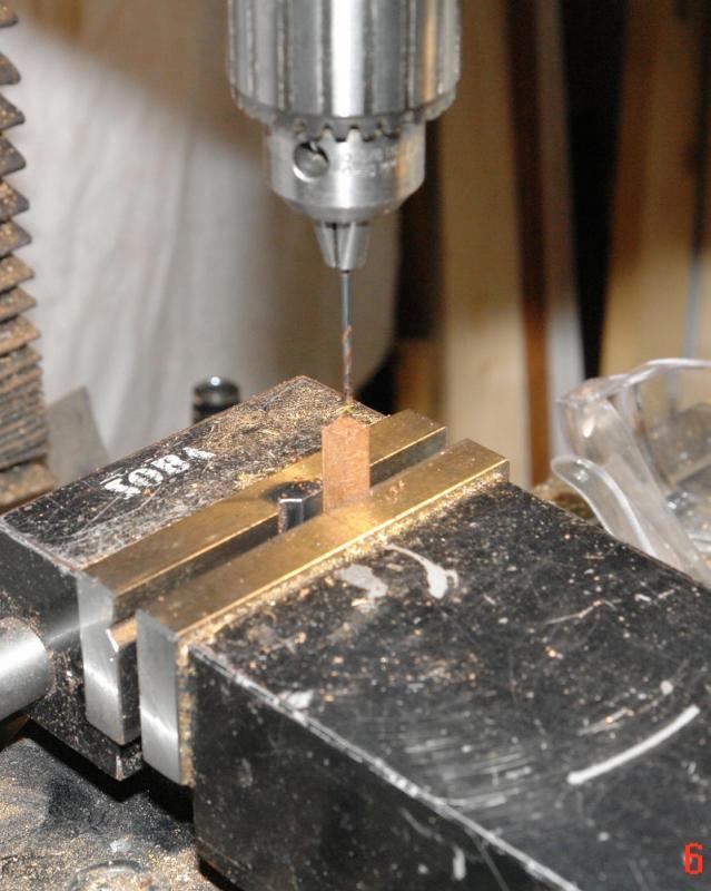
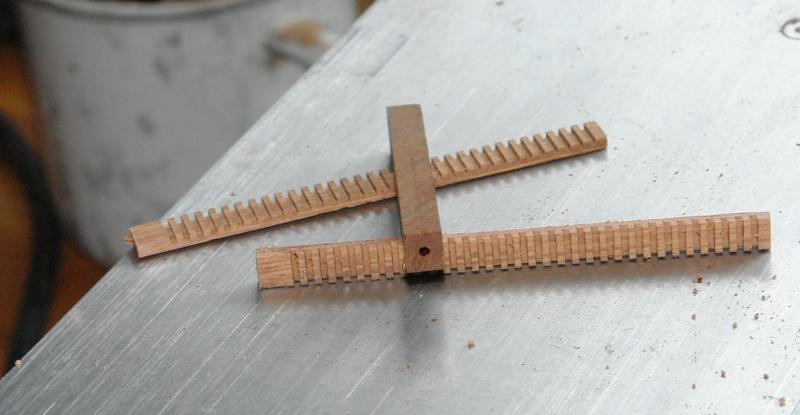
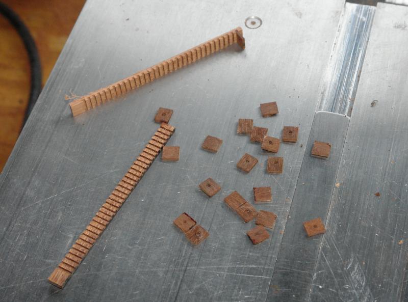
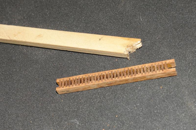
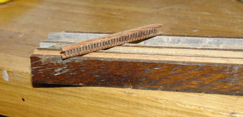
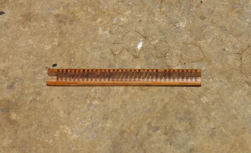
Cleats and Pulley Blocks:- On the inside of the bulwarks are cleats for attaching the fenders. 5 per side. They are fairly simple with a single central mount. I decided to have a go at making the pulley blocks. I have not made wooden pulley blocks before and decided it was worth having a try. The fall back position is buying them. Altair has single double and triple pulleys and I decided that 2 or possibly 3 sizes would cover the range needed. I started by sketching out the designs. I decided to start with the middle sized pulley block 0.2 x 0.3 inch. I need a number so decided to build them as a single unit which would allow 1,2 and 3 pulley versions to be parted off as required. I started by slotting mahogany and then cutting strips to the width of the finished pulley. I made a mistake on one of the slots - adding up becomes more difficult with age!!!!! I also cut the square block from which the walls of the pulleys would be formed. I drilled the square block to take the pulley spindle. This was a step too far as the drill was much too flexible and wandered off. Next time I will drill the spindle hole once the pulley has been formed and separated off. The wall section were slit off from the drilled block, and assembly commenced using PVA glue. Once the assembly was complete shaping commenced. I made a concave sanding block to assist control of the shaping operation. The assembly is now sanded to shape and awaiting further operations.


- 882 replies
-
- 12
-