KeithAug
-
Posts
3,986 -
Joined
-
Last visited
Content Type
Profiles
Forums
Gallery
Events
Everything posted by KeithAug
-
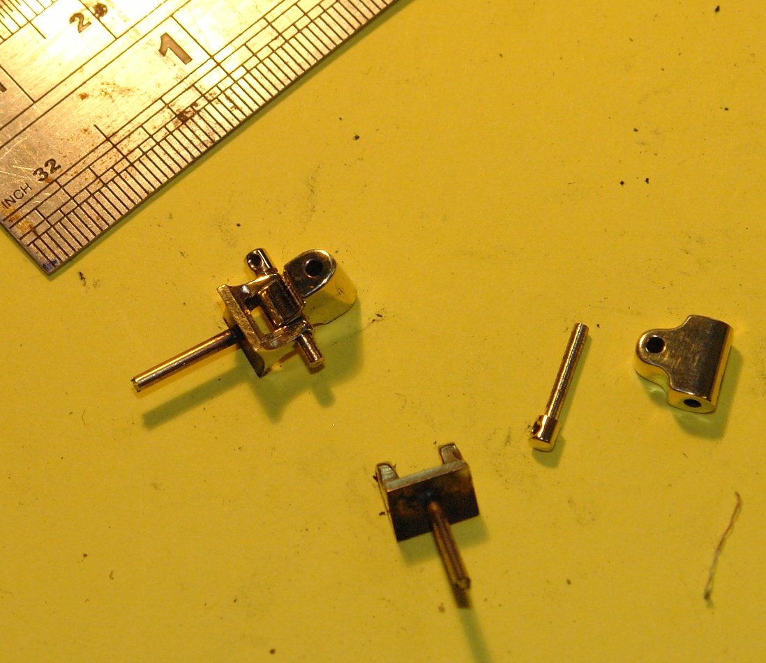
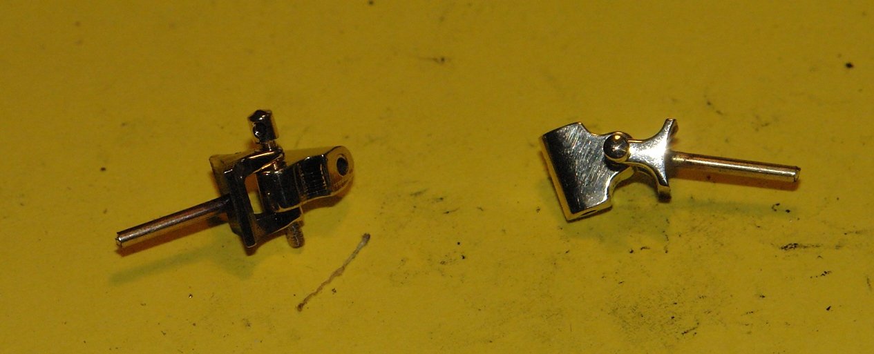
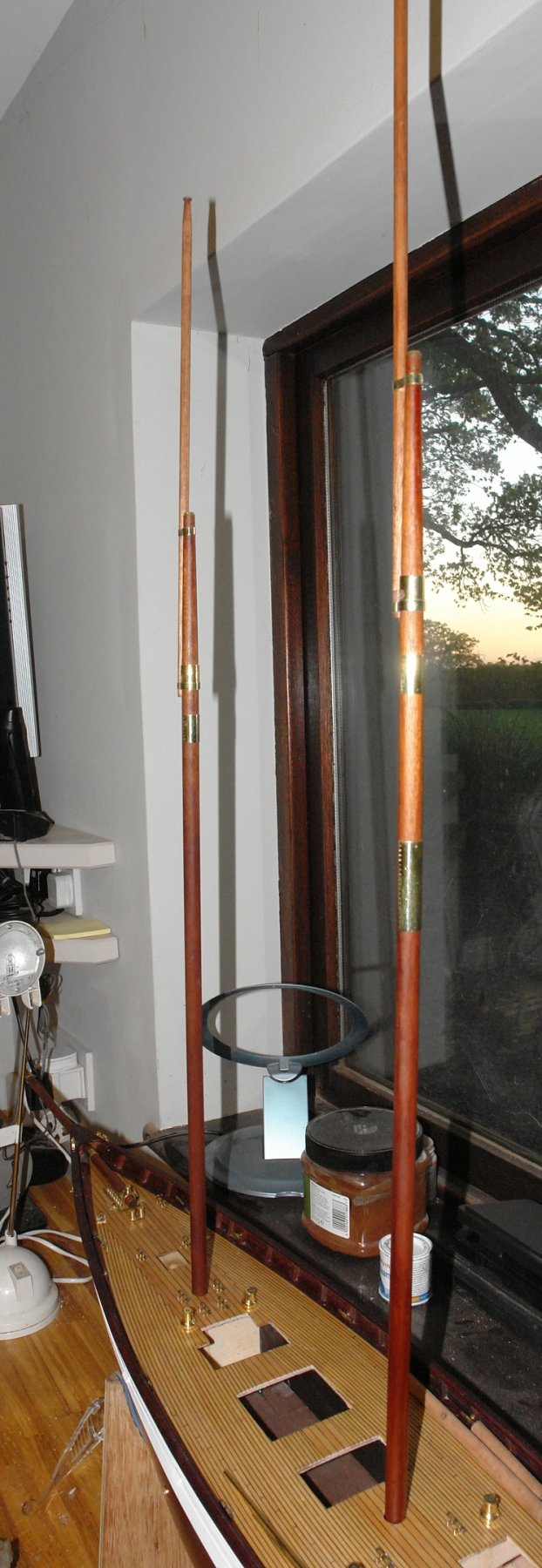
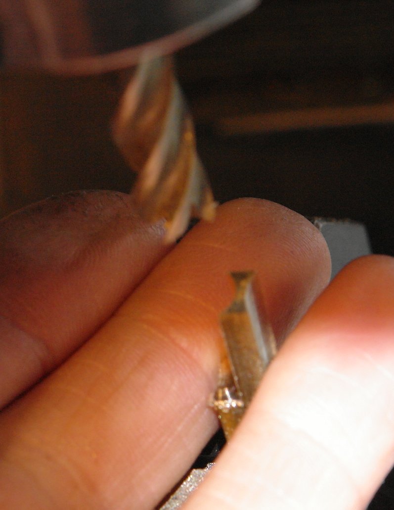
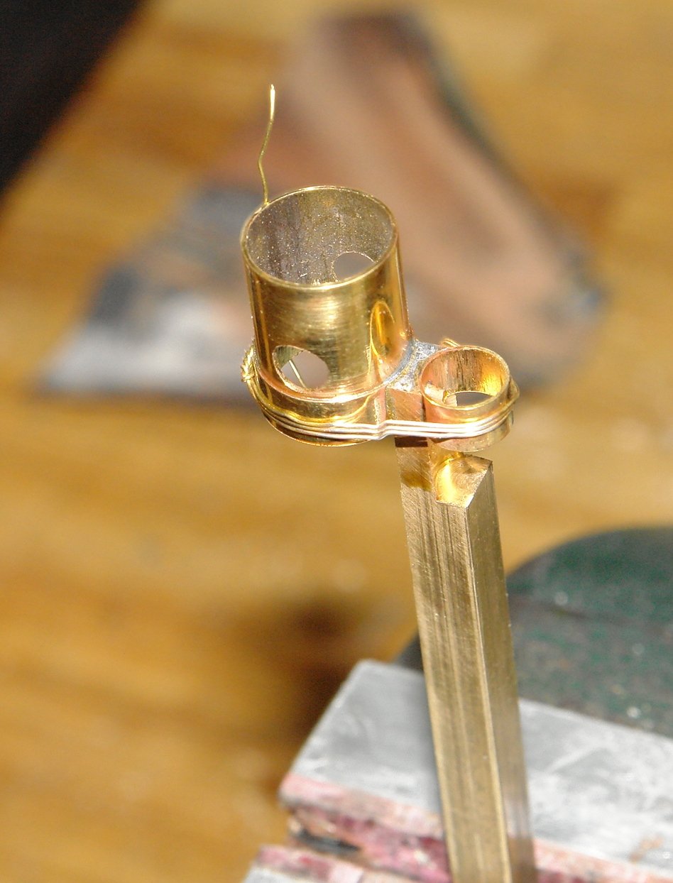
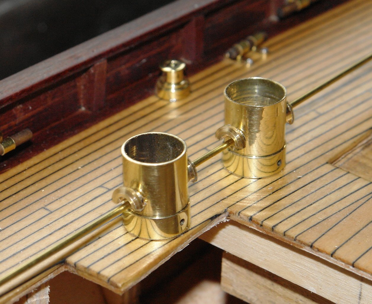
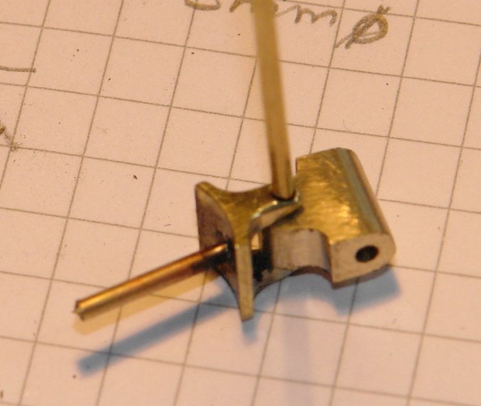
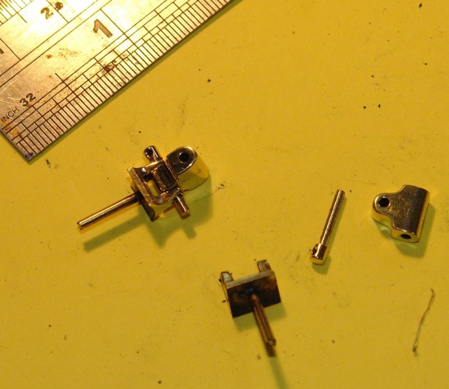
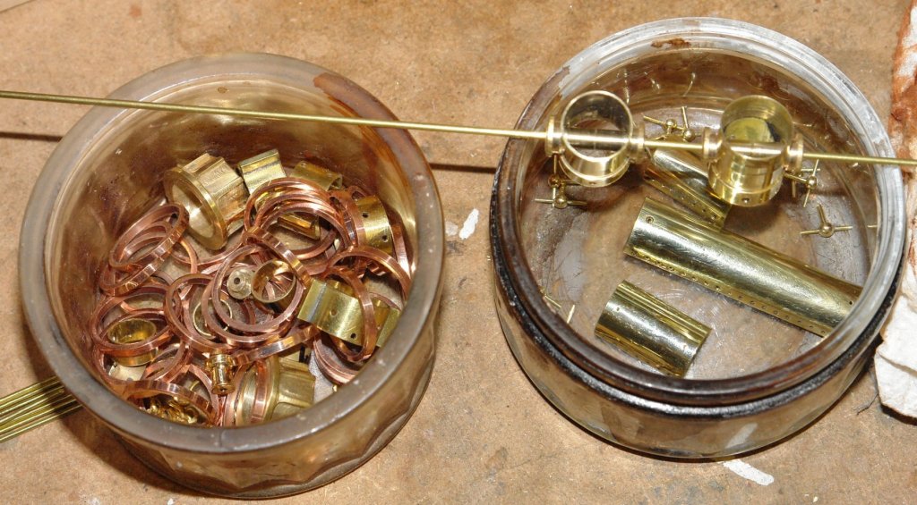
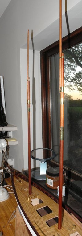
 I got a bit of time today to finish the goosenecks. Machining followed a similar process to that used for the mast bracket. The rounding of edges was done by hand filing. I then made the pivot pin - turned on the lathe out of .090" bar and drilled with a .040" hole on the mill. I then did a bit of polishing. I am accumulating a lot of mast fittings - but it will be soon time to get on with assembling the masts.
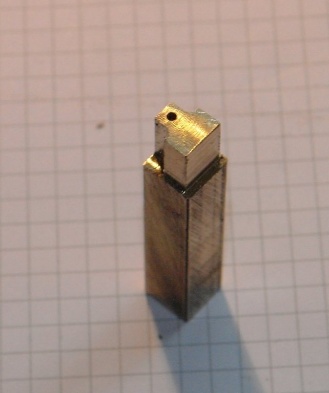

-
Dan I was impressed by the result given the process you had to go through. It looks great.
- 287 replies
-
- 3
-

-
- michelangelo
- ocean liner
- (and 1 more)
-
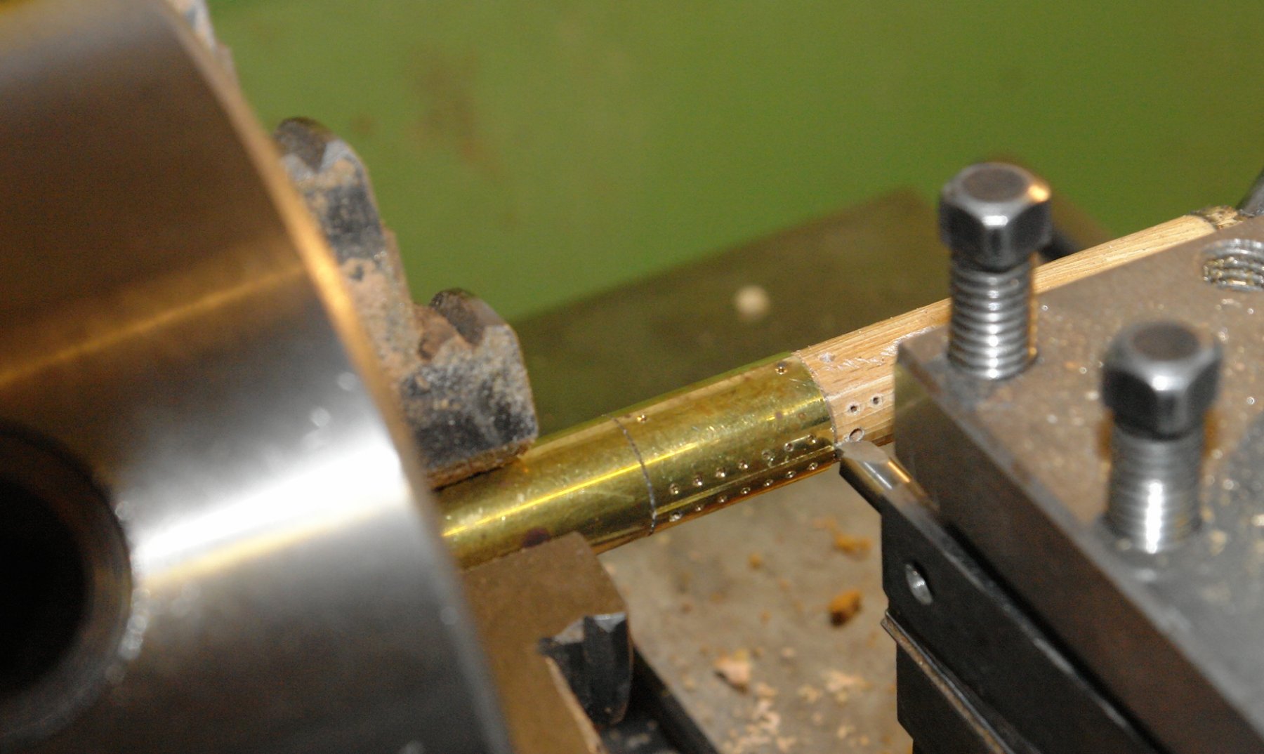
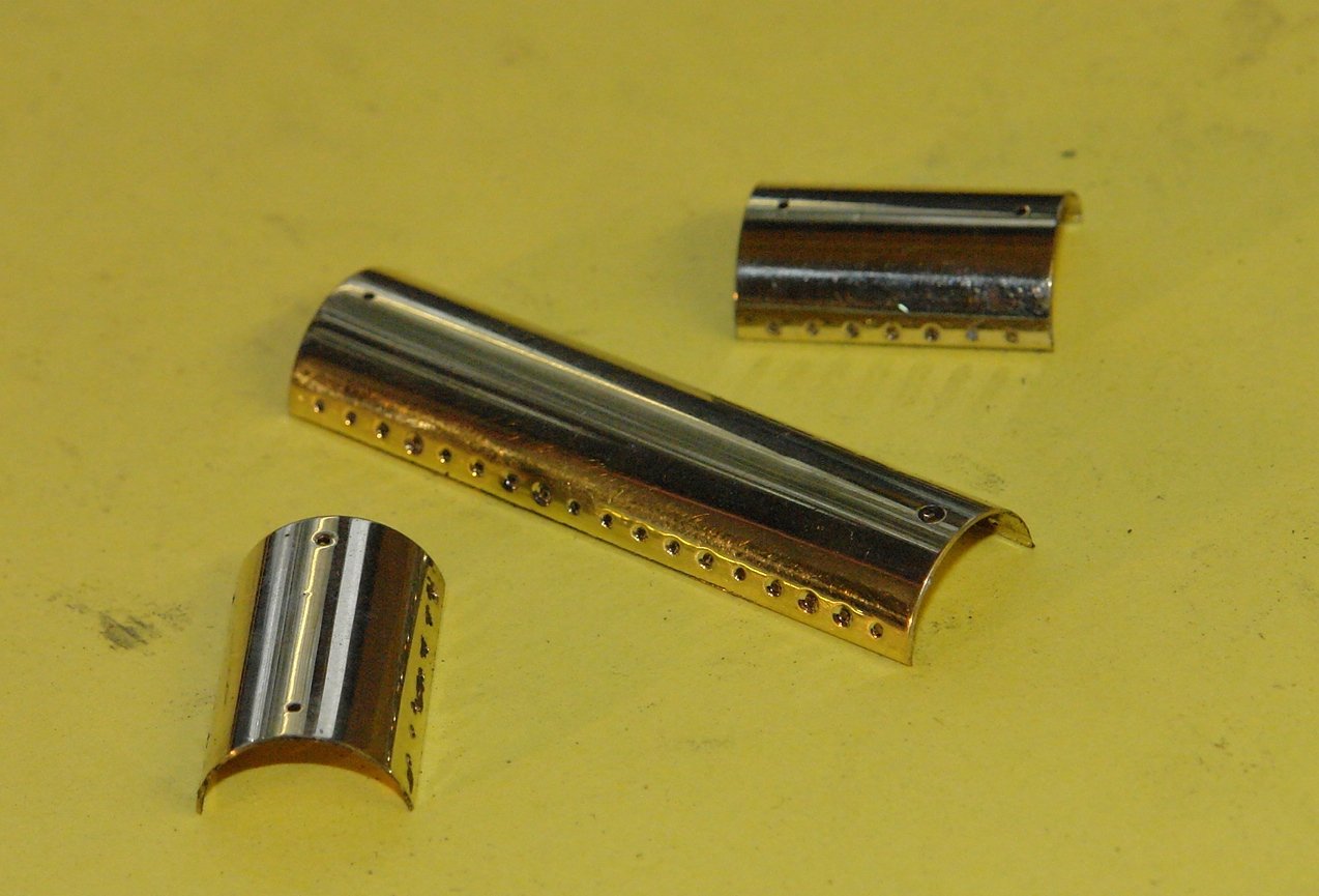
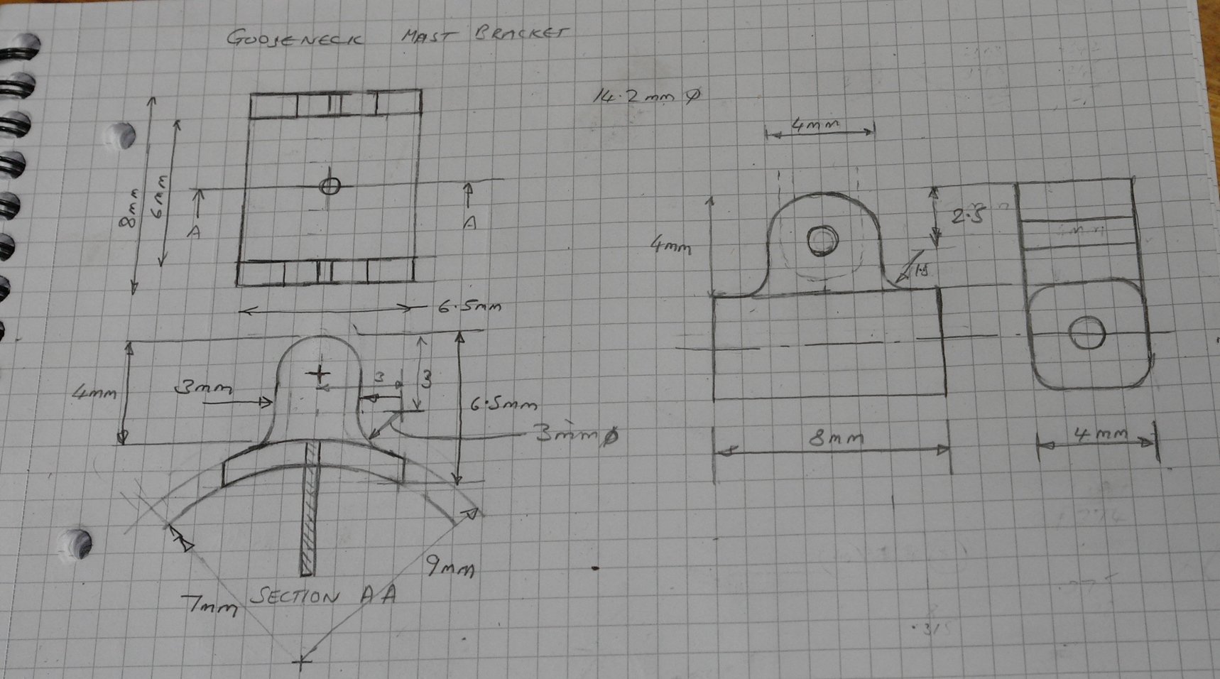
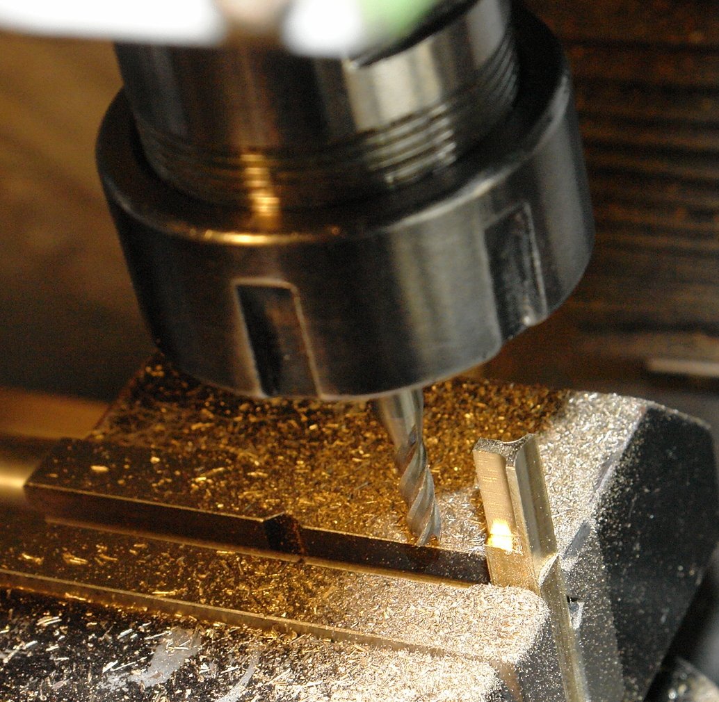
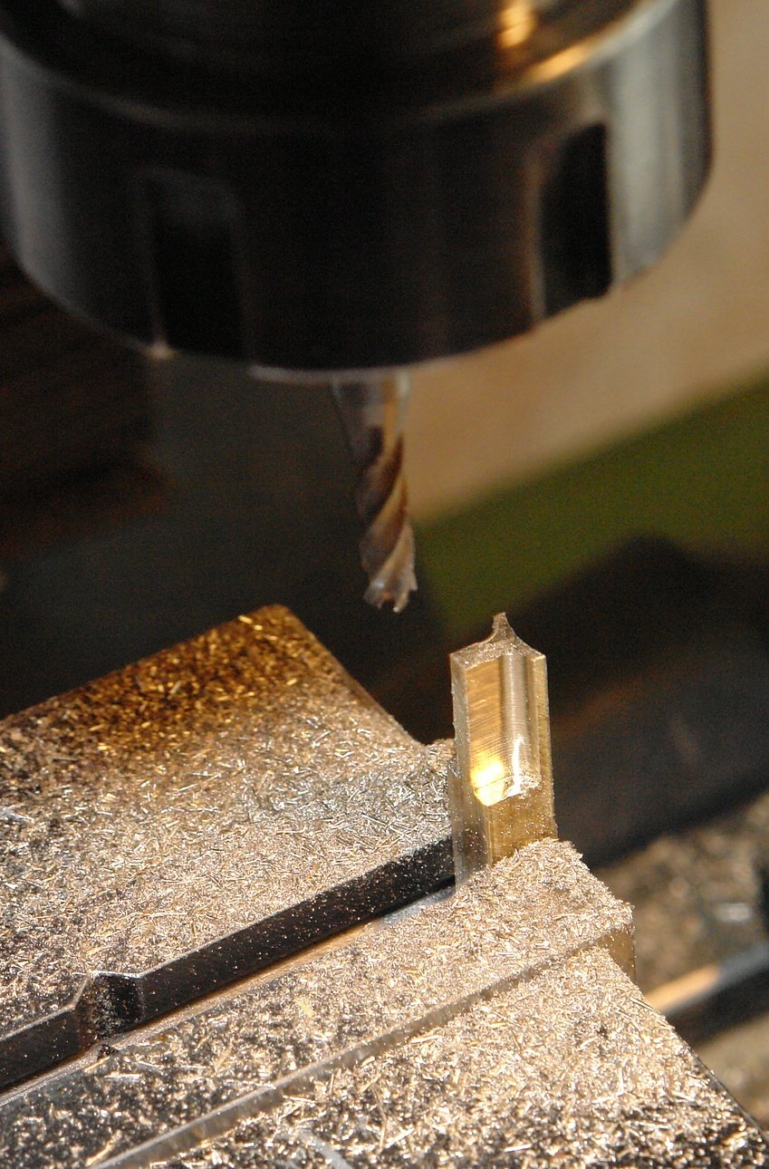
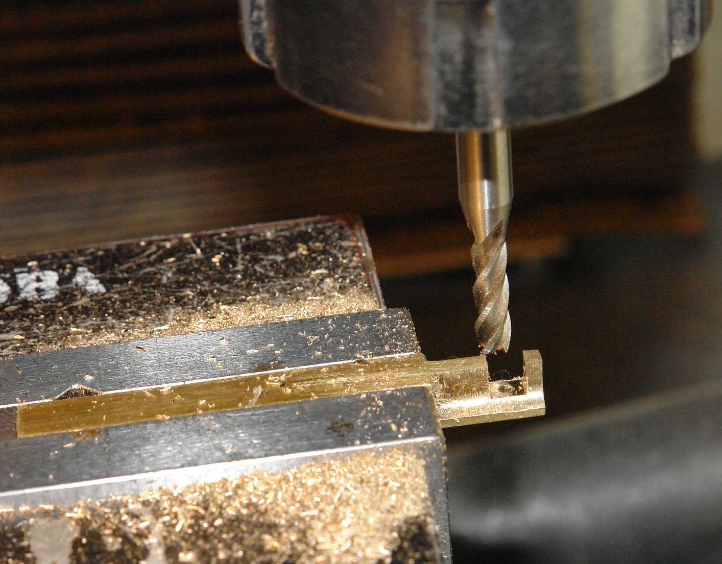
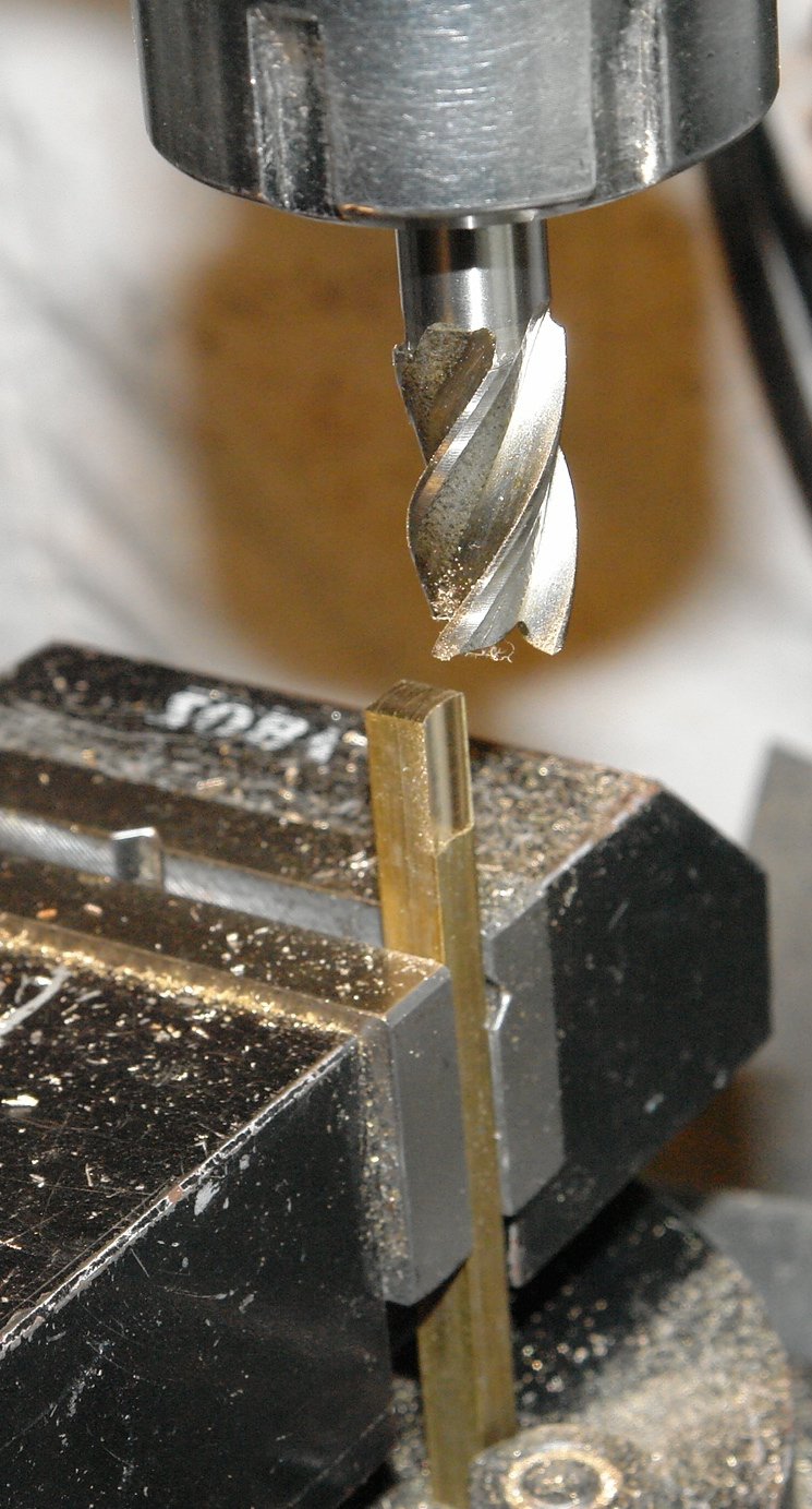
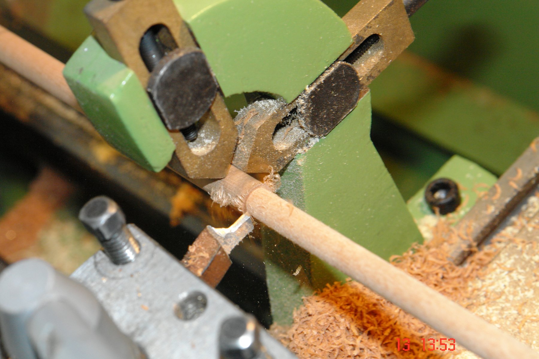
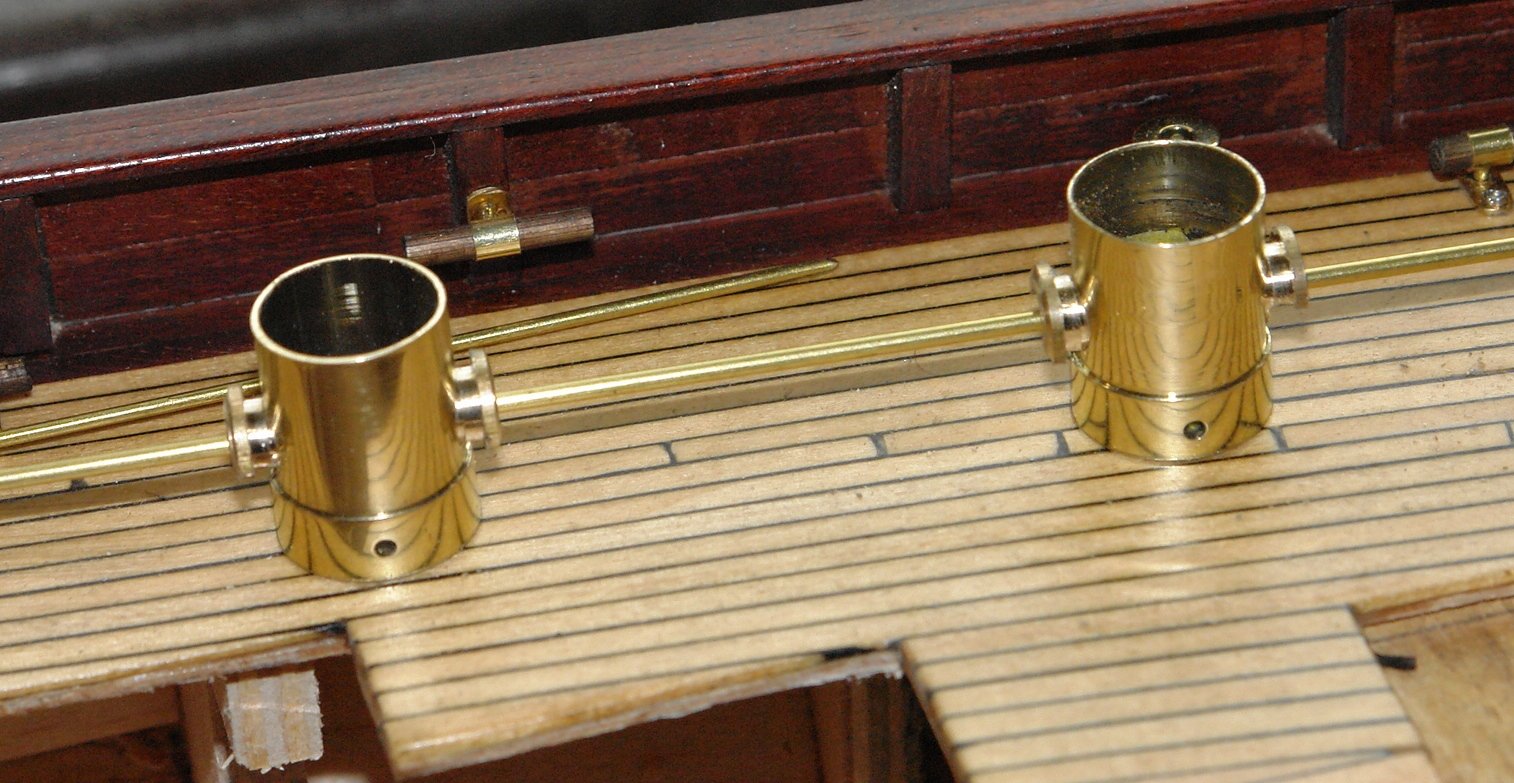
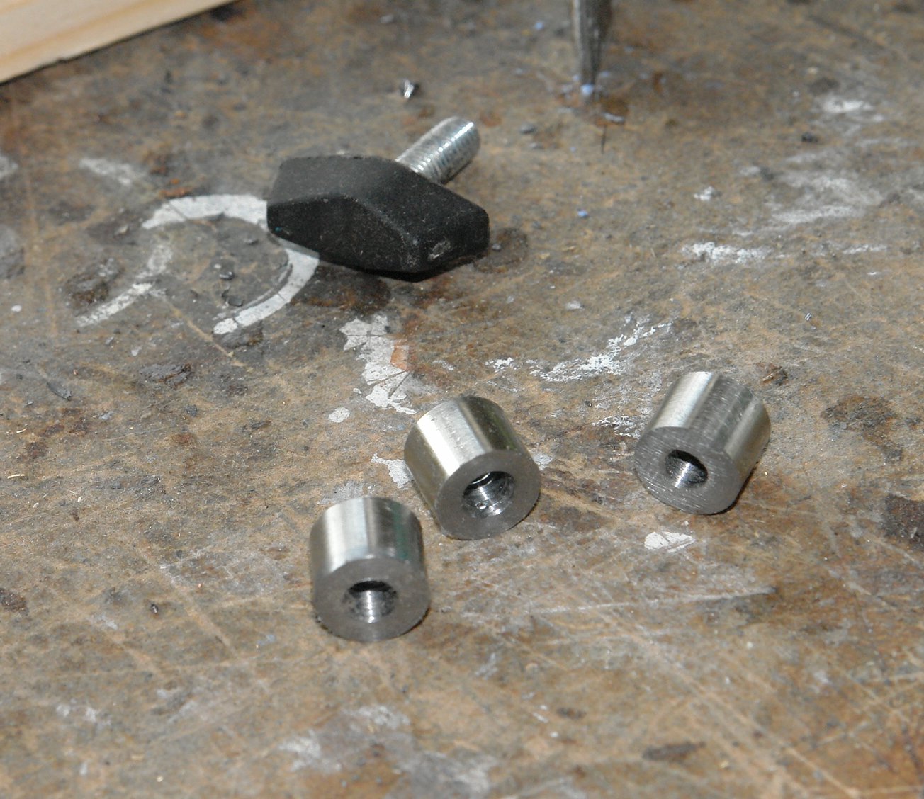
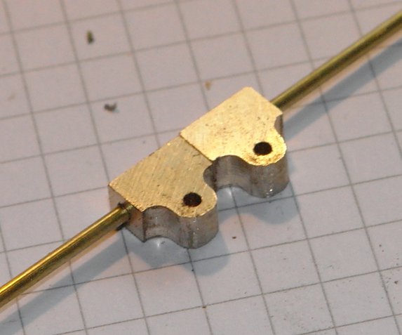
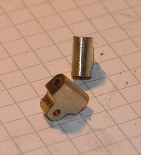
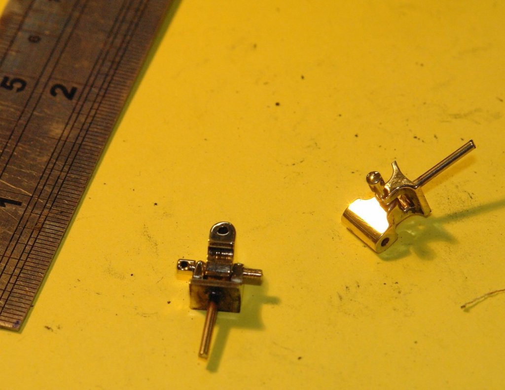
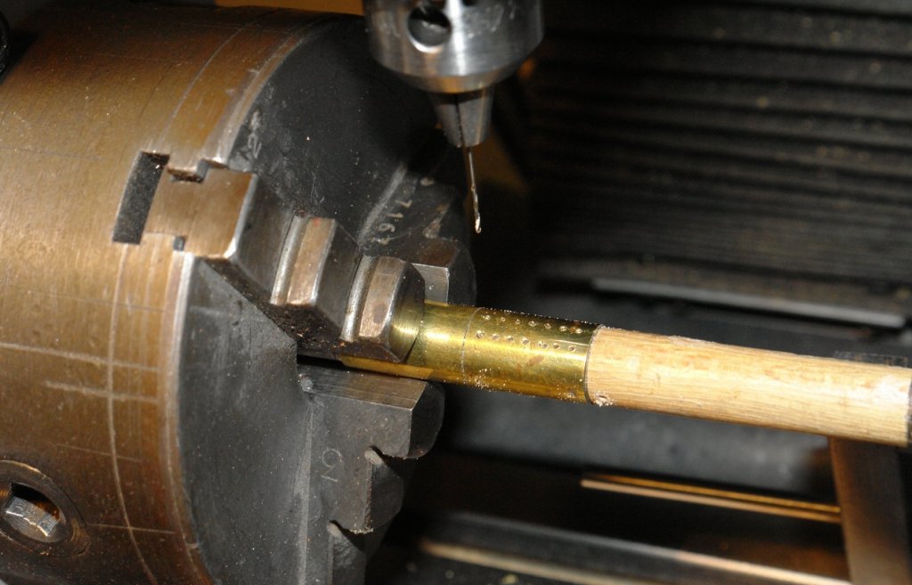
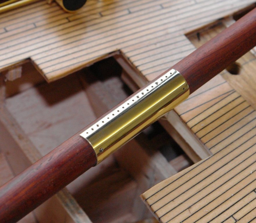
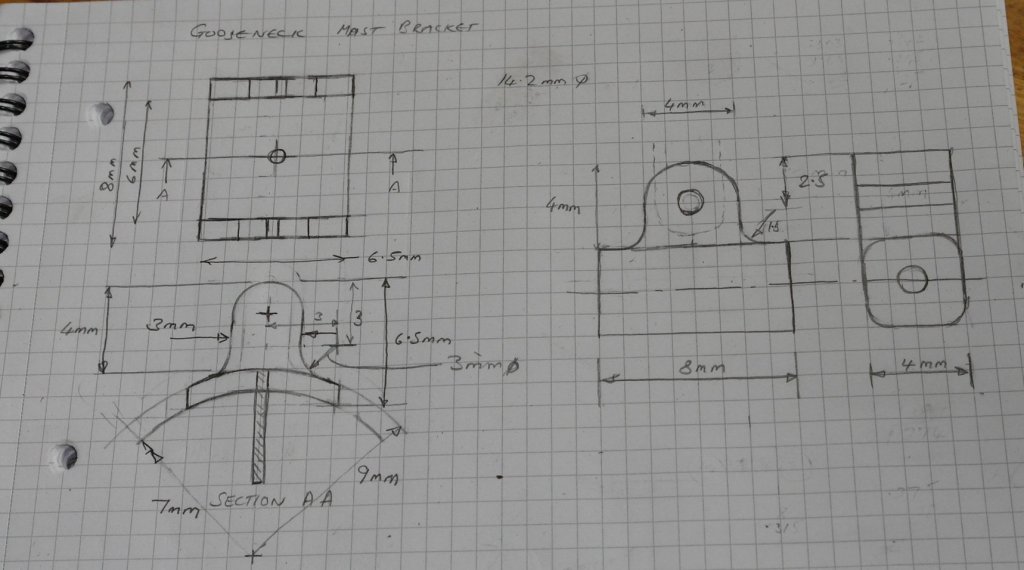
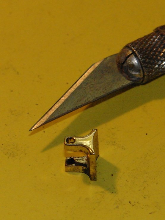
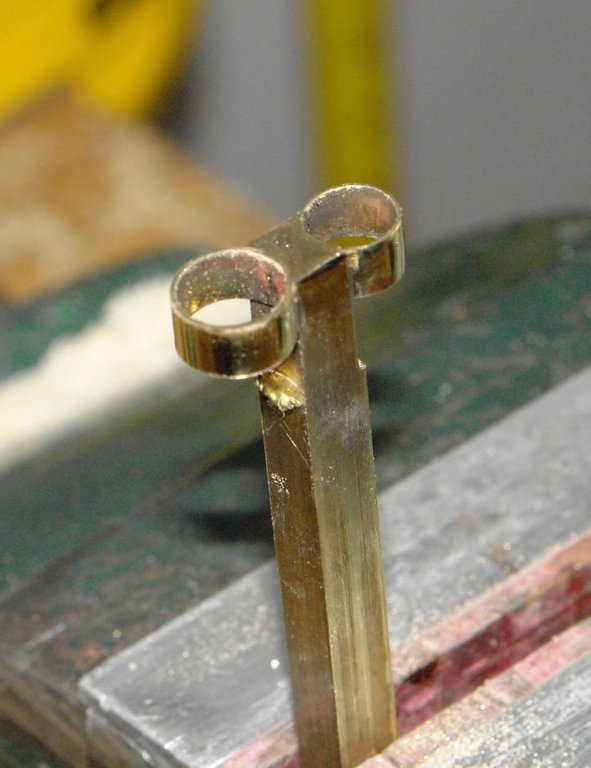
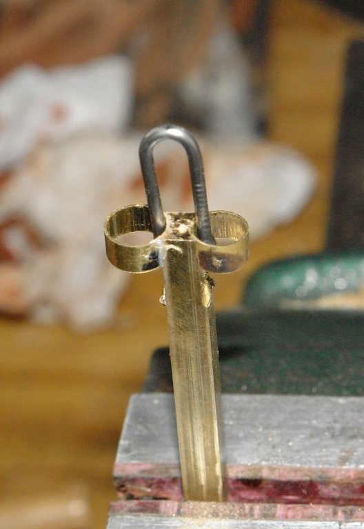
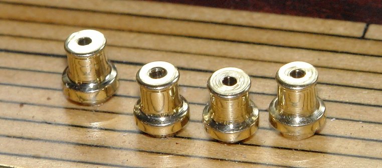
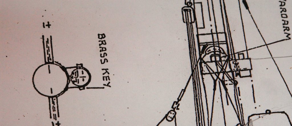
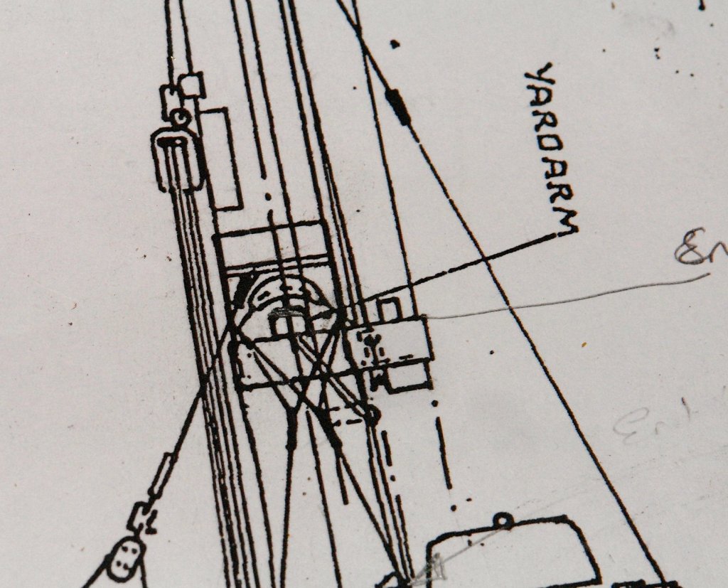
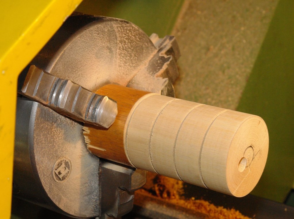
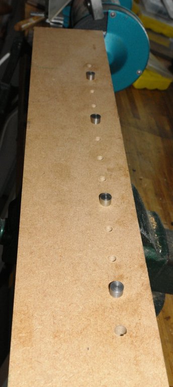
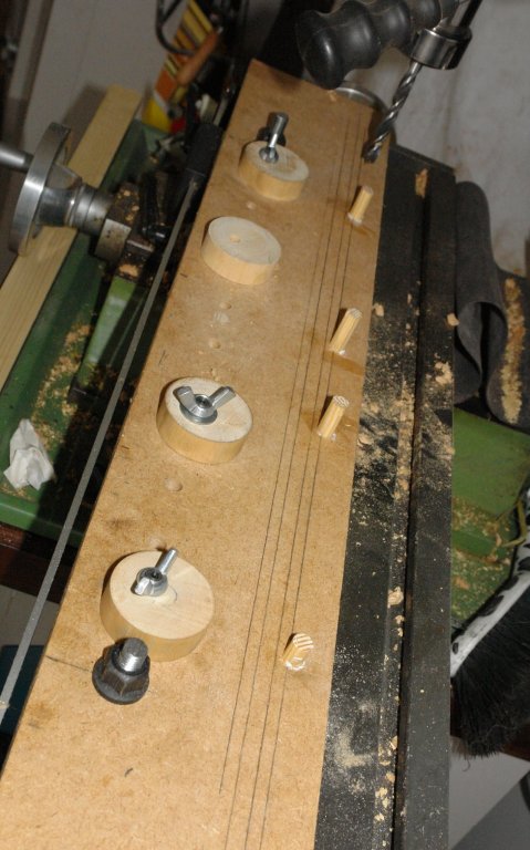
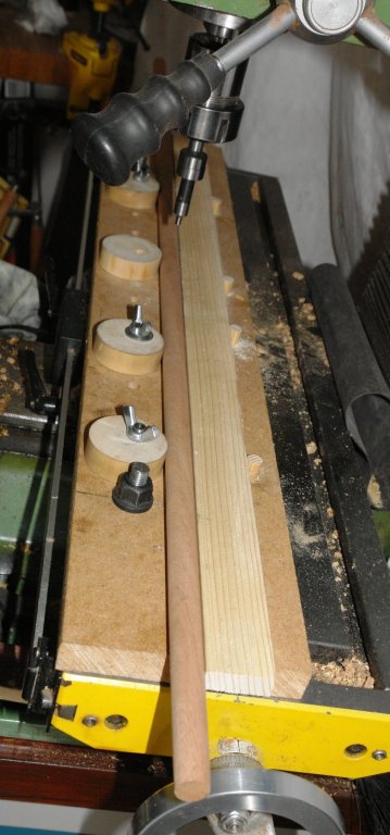
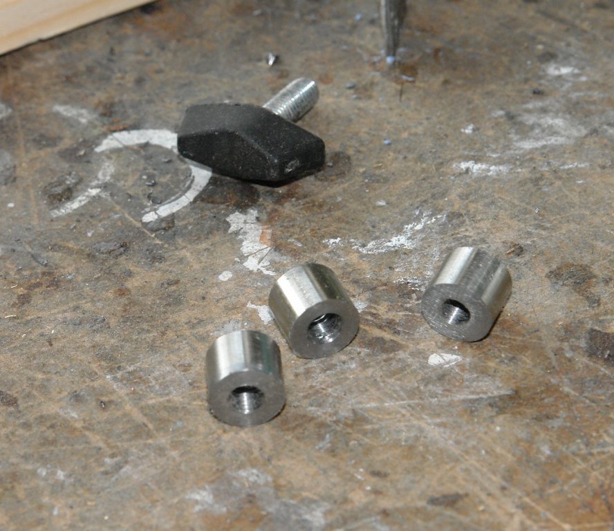
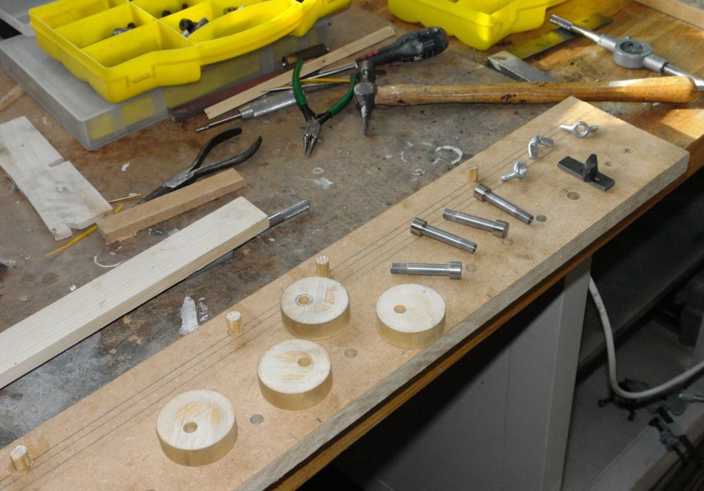
Thank you all for you feedback and likes. I'm still on mast related features. Altair has wear / pressure plates attached to the mast where the gaffs intersect the masts. These are in the form of 1/2 cylinders. On the main mast there is an additional plate about 1/3 of the way between the gaff and the deck. This is not on the plans but is very evident on photos. I am guessing its function relates to a reefed main setup. There are also a number of other smaller plates where blocks come into contact with the mast. Fortunately I did not have to bend up flat plate as I had some thin walled tube of marginally smaller diameter than the mast. I reasoned that once cut it could be pressed on to the mast to form a good fit. I wanted the tube to be neatly cut so I started by wedging it on to a dowel of correct dimeter. This was then put on the lathe and the lengths required were cut using a very sharp angled "V" tool (just about visible on the following photo). The tube (still on the dowel) was then moved on to the rotary table on the mill and lateral holes were drilled to take the mast attachment nails. Having drilled the holes the tube/dowel was moved back to the lathe and the sharp "V" tool was turned horizontal to be used as a plane to score the lateral parting line. The scoring action was repeated with .001" advancement of the tool on each planing stroke, alternating sides, until the tube parted. I then started work on the goosenecks - this is only partial complete. I started by taking the basic dimensions from the plan and then doing a better job of detailing the design. I started with the mast bracket - cut from .250" square brass bar. The bracket was machined on the mill using end mills of various diameters. The photos tell the story.


- 882 replies
-
- 13
-
-
Richard, I measured the bar (.250 x.250) and then used an edge finder to locate the edge. Having fixed the edge I indexed the mill over to compensate for the edge finder diameter. This set the mill spindle directly over the edge. I then moved it over a further .125 to set the mill directly above the centre of the bar. This video does a passable job of depicting the process https://www.youtube.com/watch?v=5_qiPE5z7SE.
-
Drill press adapter for small bits
KeithAug replied to Foultide's topic in Modeling tools and Workshop Equipment
Hi Dave Link http://www.ebay.co.uk/itm/122382958417 I am aware Little machine Shop do something very similar but it seems much more expensive. -
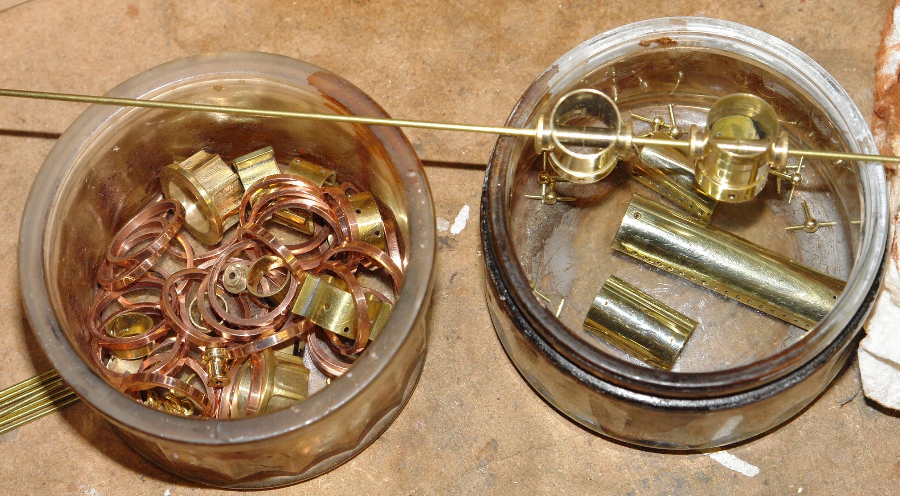
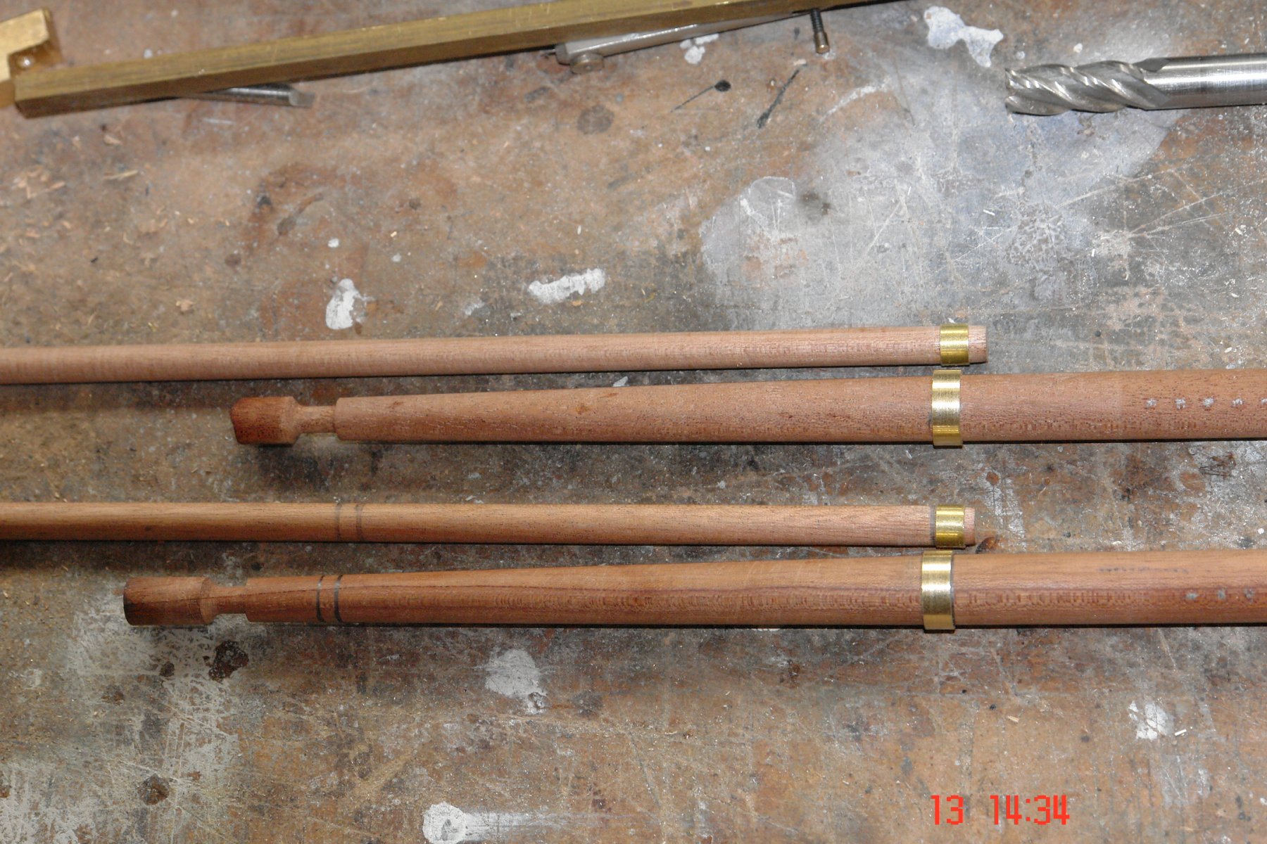
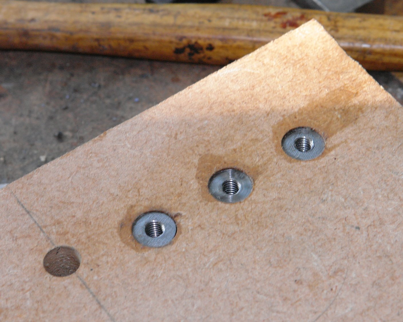
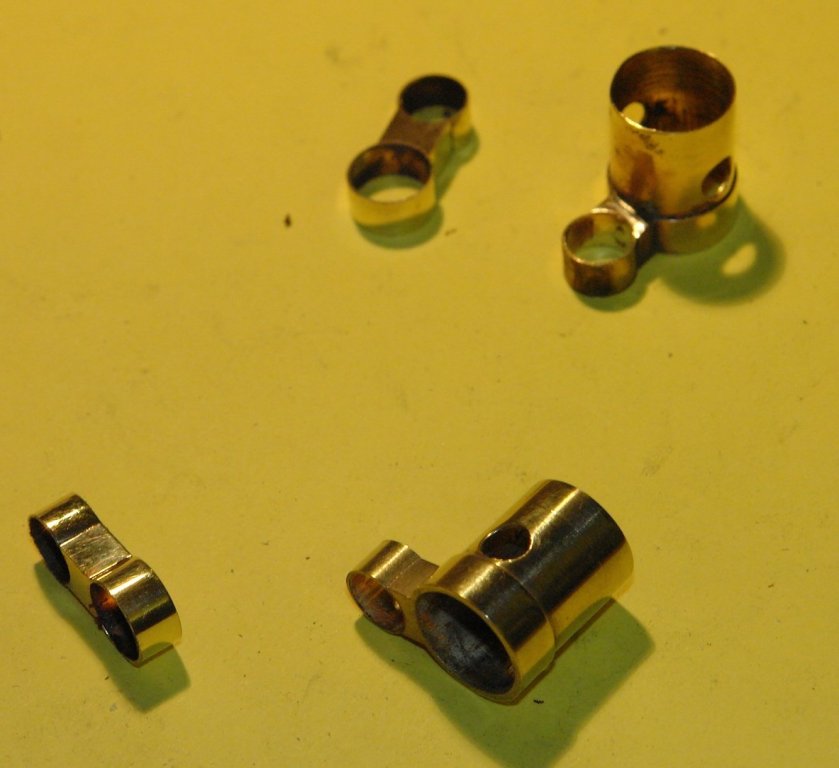
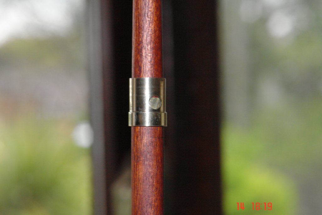
Im finding that the mast fittings are gong on a bit. Each time I look at the plans and photographs I find something else to make. Anyway here I go with another update. Today I decided to start by joining the upper and lower main and foremasts. This involved joining 8 mast collars (making 4 fitting in total). I wanted to make sure the the upper and lower masts lay parallel to one another and as the upper and lower collars were of different diameters this involved accurately sizing and making the spacers that joined the collars. The spacing pieces were profiled using differing sizes of end mill which were plunged into the 1/4" square brass bar stock. The components were then assembled for soldering. Initially I tried wiring the parts together to retain them during the soldering operation. It worked but it required a great deal of dexterity and created much frustration. I then bent a nail to form a clamp, this proved to be a much better solution. The soldered collars were then parted from the bar with a razor saw before being polished.


- 882 replies
-
- 10
-
-
Drill press adapter for small bits
KeithAug replied to Foultide's topic in Modeling tools and Workshop Equipment
Hi I was looking for something similar recently and came up with this. https://www.youtube.com/watch?v=4OWIXkFVoi0
-
Rob, Thank you. The balls were made by plunging a form tool into the brass bar. On the first ball I repeatedly checked the diameter with a calliper, advancing the tool (with the cross slide hand wheel) until the correct diameter was achieved. I then set the cross slide hand wheel scale to zero. For all subsequent balls the had wheel was advanced until it reached the zero setting. This meant that the tool always returned to a set position and hence cut the same diameter as on the original ball. I hope this makes sense.
-
Michael, Sorry my explanation was not great. I did form the ball by doing a plunge cut as you surmised. The stem was cut in the conventional way using a small parallel turning tool. It was this second operation where I needed to take small cuts. John. Thank you.
-
I hope no one was injured in the accident. The red car looks in a particularly hazardous situation.
-
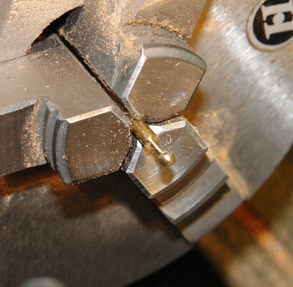
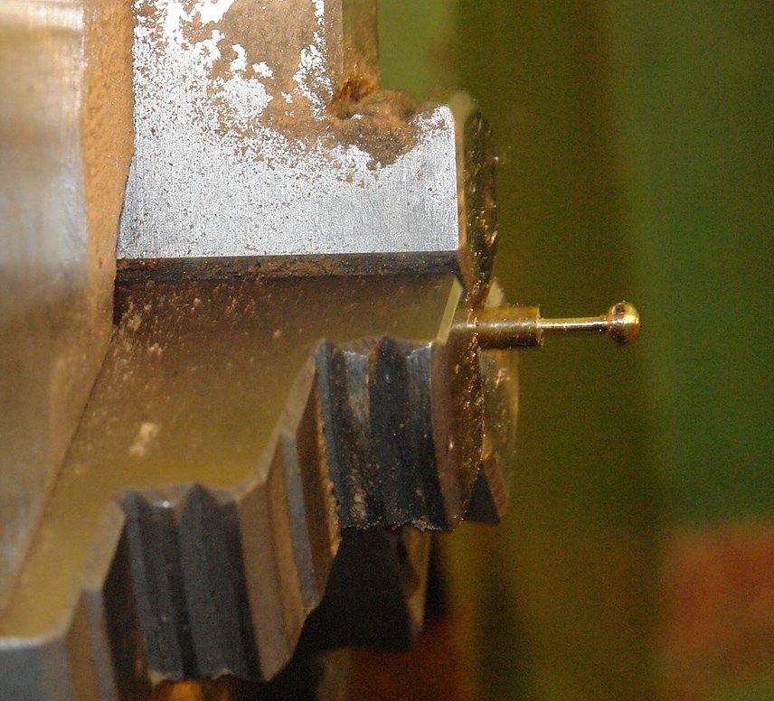
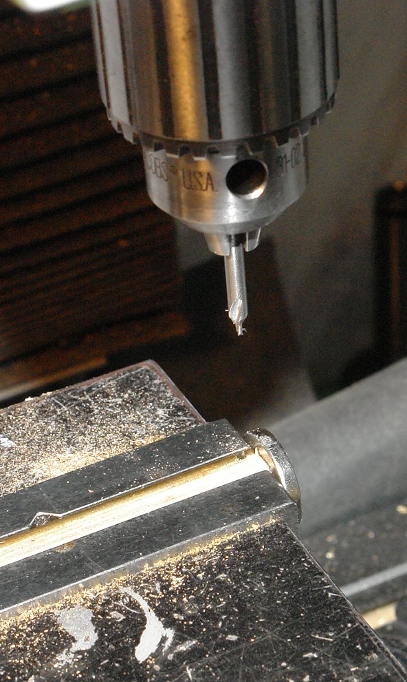
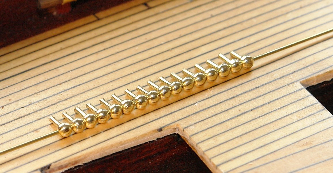
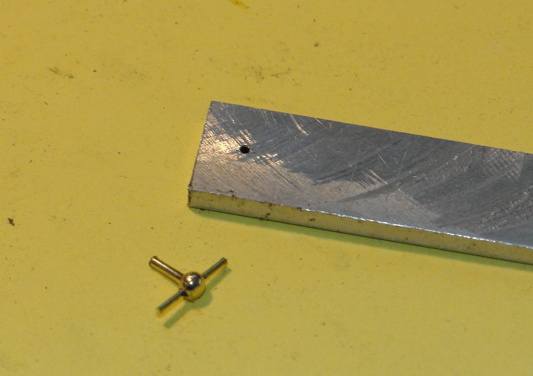
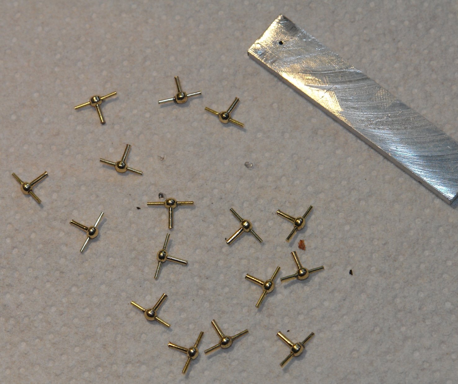
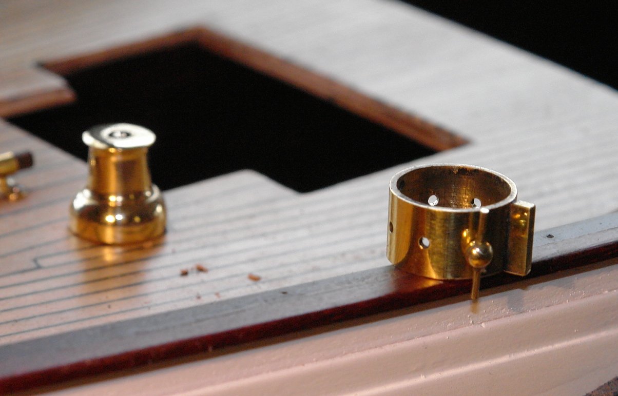
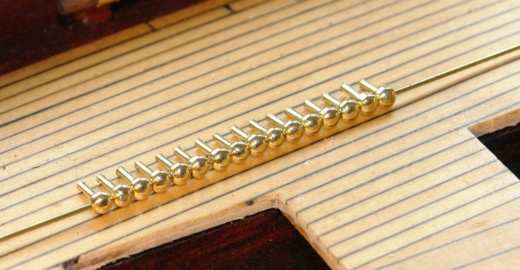
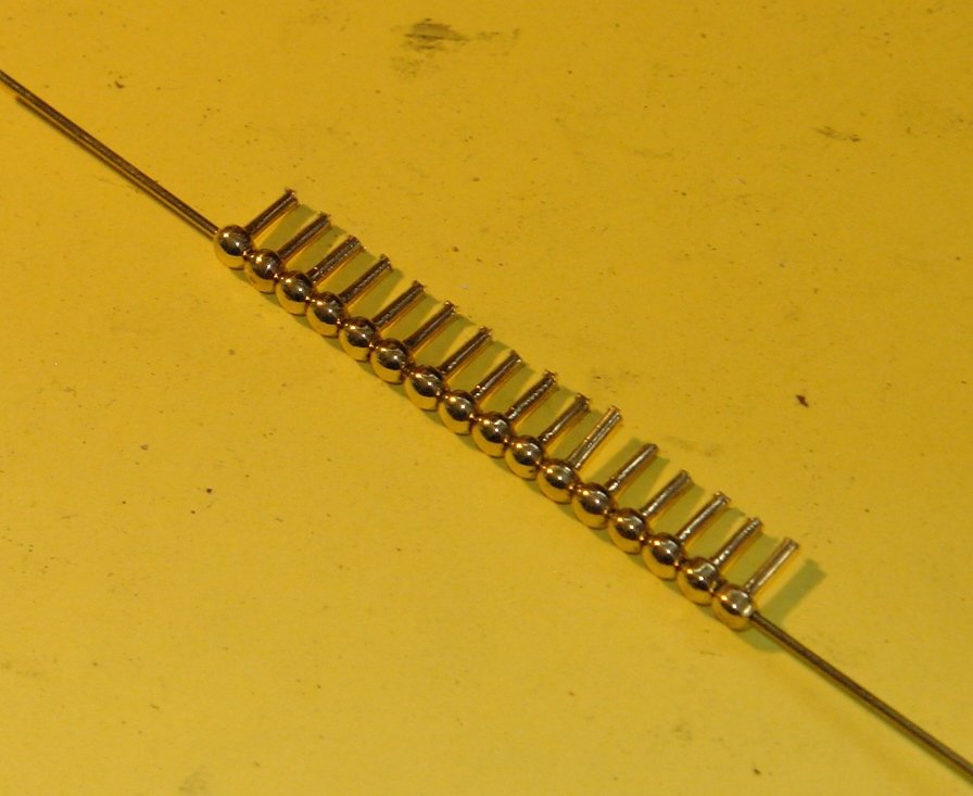
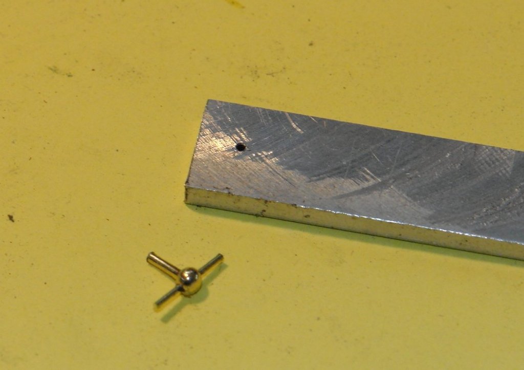
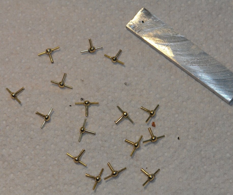
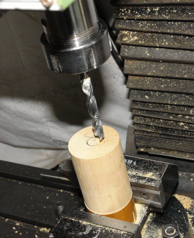
A lot of effort for such small progress............... I made a few more fittings for the masts. I turned the 4 winches for the lower spiders, 2 winches per mast, fairly straightforward turning task. The winches started as 1/4 inch brass bar and are approximately 1/4 inch long. I then needed to make the 16 cleats that fit on to the 4 spiders - these are quite small and involve turning and drilling balls of a little less than .100 inch diameter on a stem of .040 diameter by .200 long. I made the form tool for the ball out of a broken centre drill. The balls / stem components stared as .125 brass bar. Cuts had to be small to prevent breakage - typically .005" (on radius) for initial cuts reducing to .002" for finishing. I drilled the hole through the balls on the mill - using a centre drill followed by a .030" twist drill. All balls were drilled on a single setting using a magnet on the vice jaws as an end stop. The balls were drilled while still attached to the bar and parted off with a slitting saw thereafter. The initial ball / stem took about 3/4 hour to make. At the end of the run for 16 I was making them in a little over 10 minutes. The cross member of the cleat was wire, cut glued and then filed to length. The aluminium plate in the photo has a small hole and this was slotted over each end of the wire as a filing guide. The thickness of the plate giving the required arm length of the cleat. The end result will look something like this.


- 882 replies
-
- 11
-
-
Richard, Thank you. Yes - unfortunately no photos. Being at the top end of the mast its usually in the distance and masked by sails. Sometimes guesswork is the only way forward. At least I have the advantage that the subject still exists. Many modellers on this forum seem to do very well with old drawings of ships long since departed. Ian, Thank you for your very nice comments. Its sometimes good to get another perspective. The builders eye can tend to focus on all the mistakes and miss the bigger picture.
-
Hello Michael - good to see you back. I tend to get a good tongue lashing from my wife when I try to push recovery along too quickly. She is always right of course. Take it easy. Yes good point about copper plating. My scrap box accumulates unused copper and I occasionally get seduced into using it when I think the machining is less complicated. I then regret it and for a while the memory prevents repetition. What I really need is a metals exchange.
-
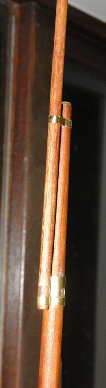
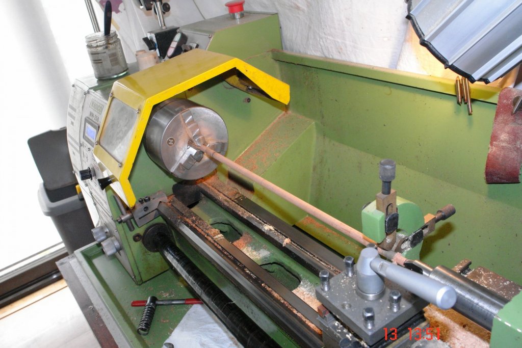
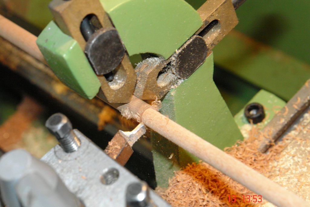
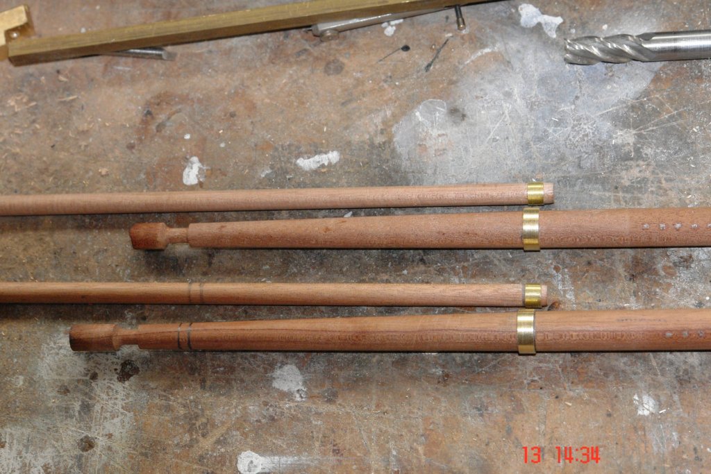
Im slowly working my way through the masts. I needed to turn down the dowels for the upper main and foremasts. I had to break out the travelling steady as the masts are .300" diameter by circa a foot long. Much too flexible to be turned without the steady. The steady sees the light of day about once every 5 years. I needed various collars - nothing too exciting here. I spent a long tome thinking about how I was going to make the rather complex collar that joined the upper and lower masts. Its complex because it has a number of appendages and also takes the mountings for the yards. The drawings don't make it easy to interpret. I started by turning the collar - the widest on the mast. I then scratched my head for a long time trying to work out how I was going to make the anchor points for the strops at the the upper ends of the shrouds. These were made more difficult because they wrap round the top of the yards. In the end I think I worked out the best way of doing this - although as yet it is only half complete. Here is the progress thus far. I should explain I need one for each mast - hence 2. The .056 wire through them will be cut and will insert into the yards.


- 882 replies
-
- 10
-
-
Tecko Loved the approach to pulley making. Its wonderful how the lack of a lathe stimulates ingenuity.
-
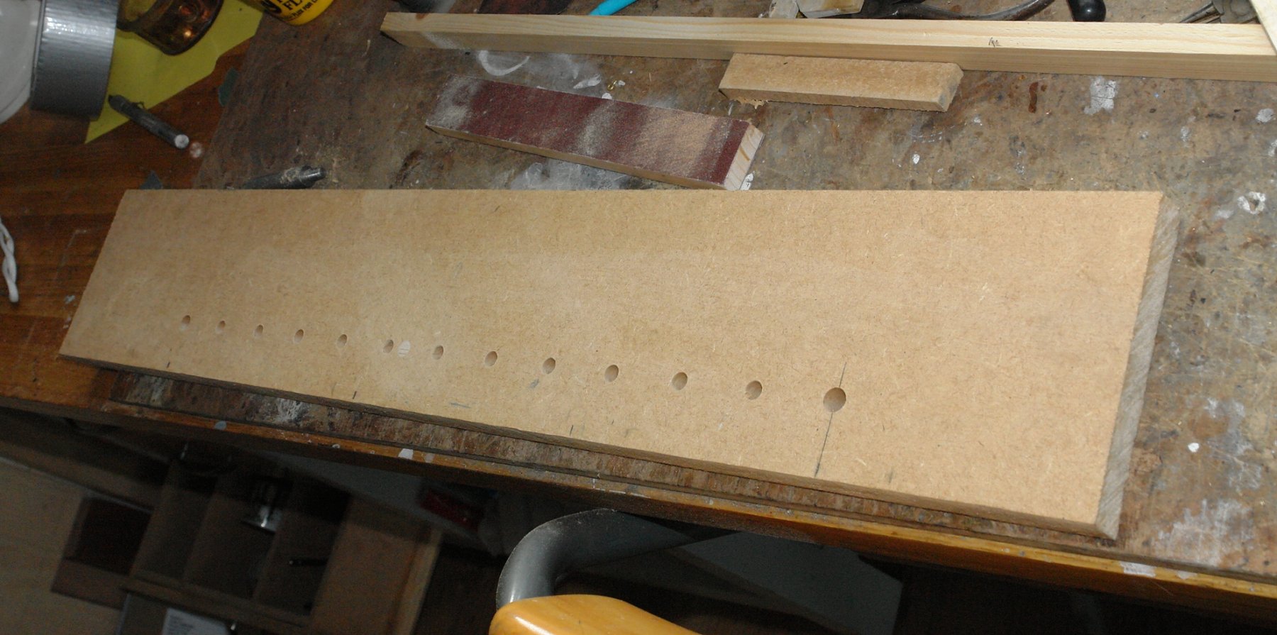
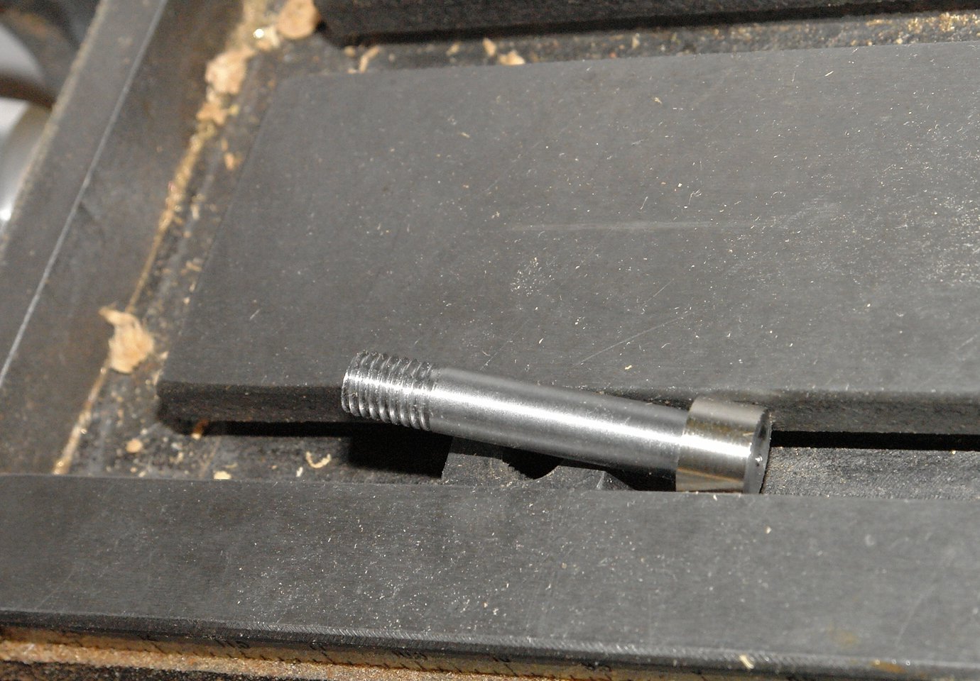
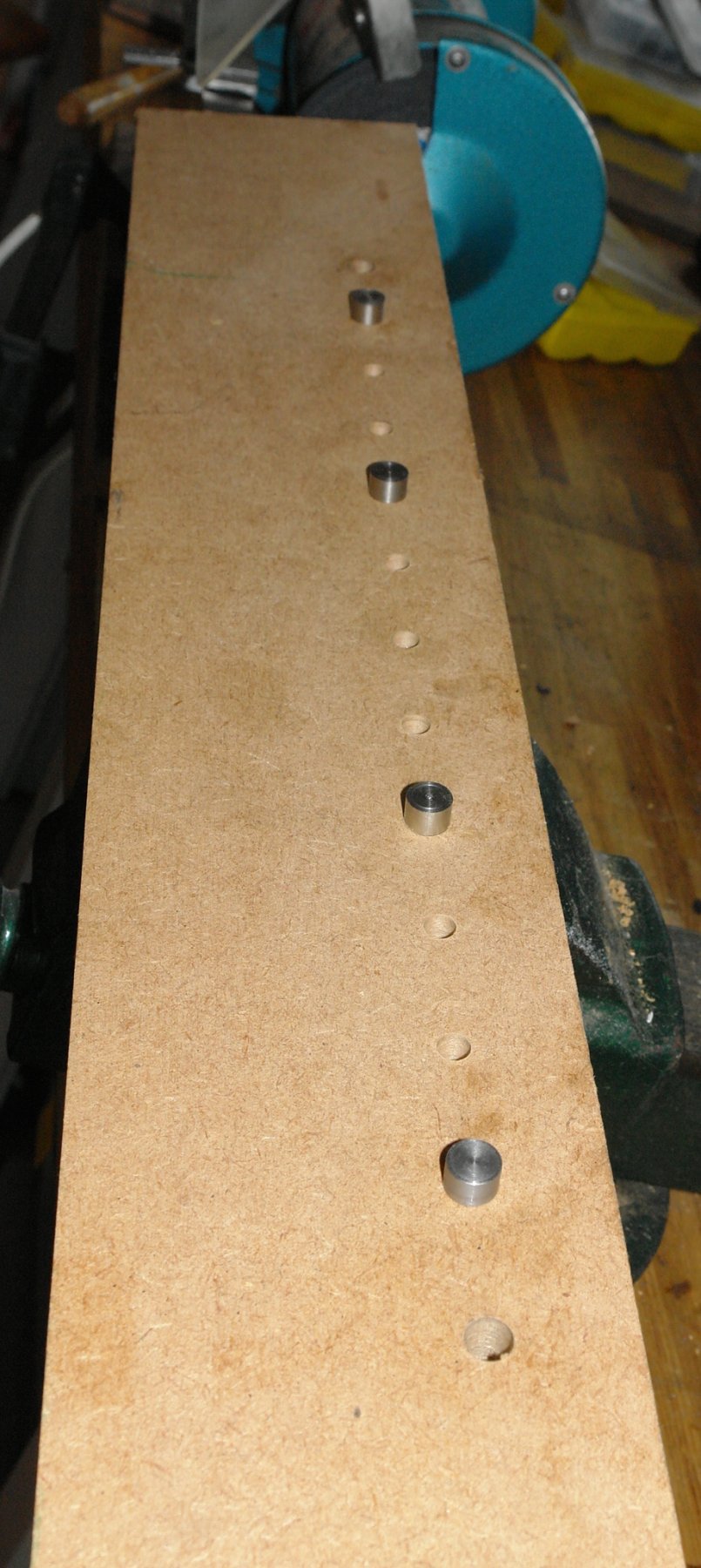
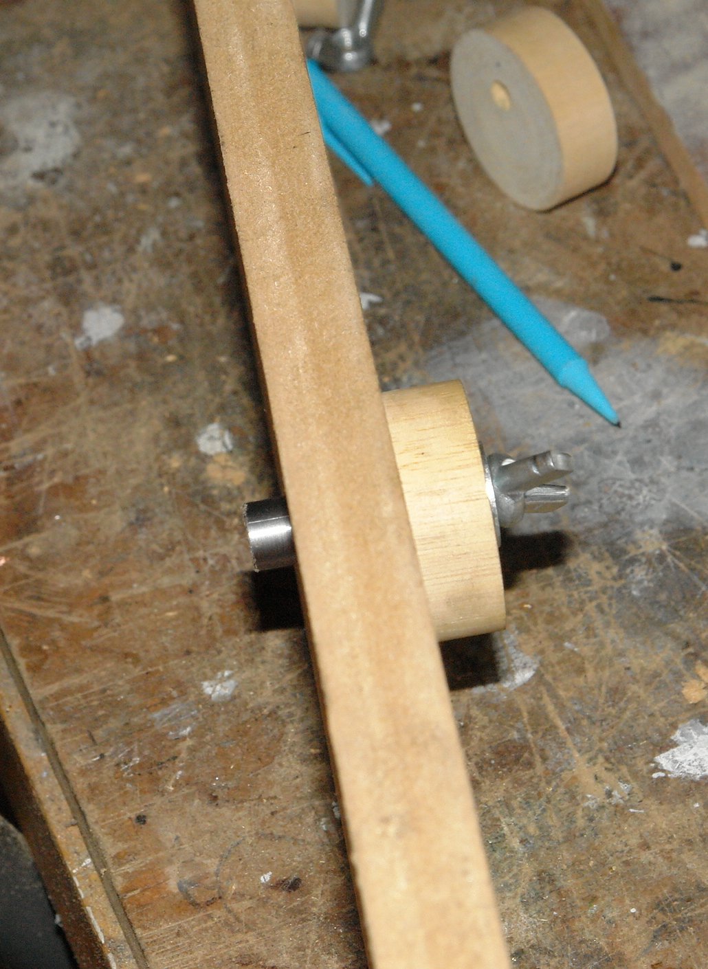
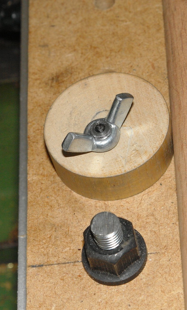
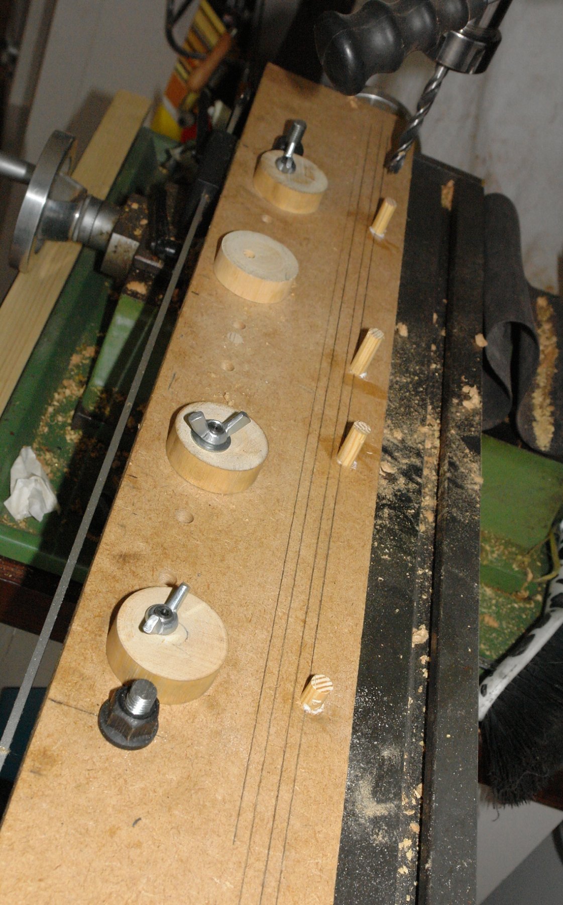
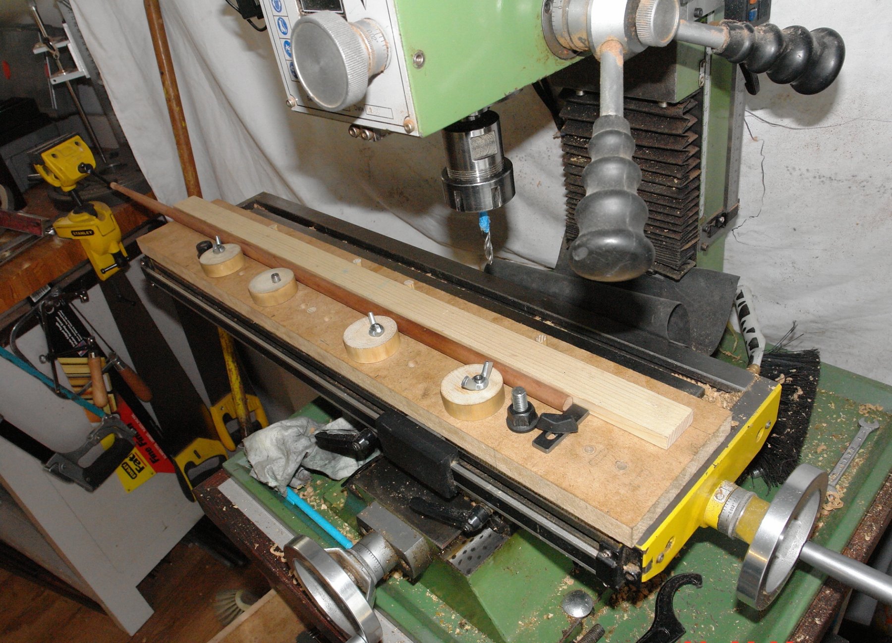
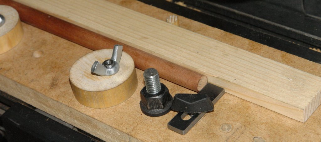
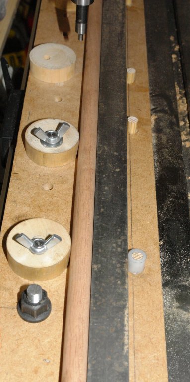
In the past I have constructed many ad hoc fixtures to enable the accurate machining of masts, spars, yards, booms etc. I decided to have a go at making something more versatile that would work for items of different shapes and sizes. Having made it it seems to work well so I thought it would be worth sharing. I started out with a set of design aspirations. For ease I will refer to "masts" rather than go through the full range of parts each time. 1 Provide solid clamping along the length of the mast. 2 Locate / relocate on the milling table without the need for alignment / set up. 3 Positively locate and relocate the mast so that I can easily remove and replace it on the mill. 4 Clamping devices not to mark / damage the mast. 5 Clamp parallel and taper masts. 6 Clamps to be easy and quick to operate. I started with a clamping concept based upon eccentric circular cams and the build started by cutting a piece of 3/4" MDF to sit on the milling table. I used the mill to accurately drill a series of holes along the length of the MDF to take the cams. The cams themselves were turned (circular) from hardwood. An eccentric hole was drilled along the axis of the cams before they were separated. The cams are mounted on the MDF using a pin. The pin protrudes below the bottom surface of the MDF and the protruding part is cut to a diameter .001" smaller than the slot in the milling table. Once the pins are pushed into the MDF they give positive and repeatable location on the milling bed. The top of the pin locates the cam which is locked by a wing nut. The additional holes allow the cam positions to be varied to suit the mast being worked on. Holes at either end of the MDF take the "T" nut bolts which attach the MDF to the milling table. The MDF was then placed on the milling table (located by the pins) and a row of 4 holes were drilled parallel to the pin holes. Into these holes were placed accurately made dowels. These dowels provide the "fixed" support against which the cams clamp. I think this will become clearer in later photos. A simple piece of wood is then placed up against the dowels. This forms the face against which the mast is clamped. In the following picture a mast is clamped in place. Because the cams act as a finely tapered wedge hand rotation is enough to very rigidly hold the mast. The cams give a lot of flexibility on the diameter of mast that can be held - .200" to .700". But larger is possible by using a narrower wooden strip. At this stage I checked the alignment of the mast to the axis of the mill. The run out was .0015" over a 12" length. Much better than I expected. I did however need an end stop to control the position of the end of the mast. This was relatively easily achieved and for good measure I included an option for 3 positions. See Photos:- The solution to dealing with taper masts is straightforward but does require a bit of trigonometry. The taper is achieved by changing the diameter of one of the fixed dowels. This is done by making a collar to fit over it. This gives a triangle the base of which is the distance between the first and last dowels and the "opposite side" is the thickness of the collar wall = (outside diameter - inside diameter)/2. In the last picture I replaced the wood strip by a steel bar - but this proved to be un-necessary. I still have a few bits to develop but I think thats enough for now - except for the mystery of the missing wing nut!!!!!!


-
Richard / Tecko, thanks for the feedback. Dan, Thanks for the tip. We have an induction hob which does not like experimentation. Fortunately the oven has no such restrictions and has an inbuilt (very hot) cleaning cycle. I'll have a go when its next due a clean. Bedford - the trouble is I am getting to the age where I forget what I have learned. I hope your memory banks are better than mine. To continue:- Altair has various masts, spars, booms and yards. All of which require numerous drilling and machining tasks. In the past I have improvised various solutions for accurately positioning, clamping, and repositioning them on the mill table. Rather than improvise for each item I though i'd spend a couple of days making a jig to take a range of diameter, and also deal with tapers. I wanted the jig to be quick to set up, hold the item firmly and ensure accuracy of position / machining. Also I wanted to clamping to be kind to the item and leave no marks. The result is pictured below. Rather than explain the build here I thought I'd do a piece in Workshop equipment.

-
It's all looking very neat and professional Per. I'm looking forward to the wheel.
-
Tecko How long did all that lot take? Moving along very well and very fast.
-
Tecko, Im really enjoying this. I had a look at the bridge on google maps - it shows up quite well. The panel reminds me of the ones I used to see when I designed nuclear reprocessing plants many years ago.