


Cathead
-
Posts
3,532 -
Joined
-
Last visited
Content Type
Profiles
Forums
Gallery
Events
Everything posted by Cathead
-
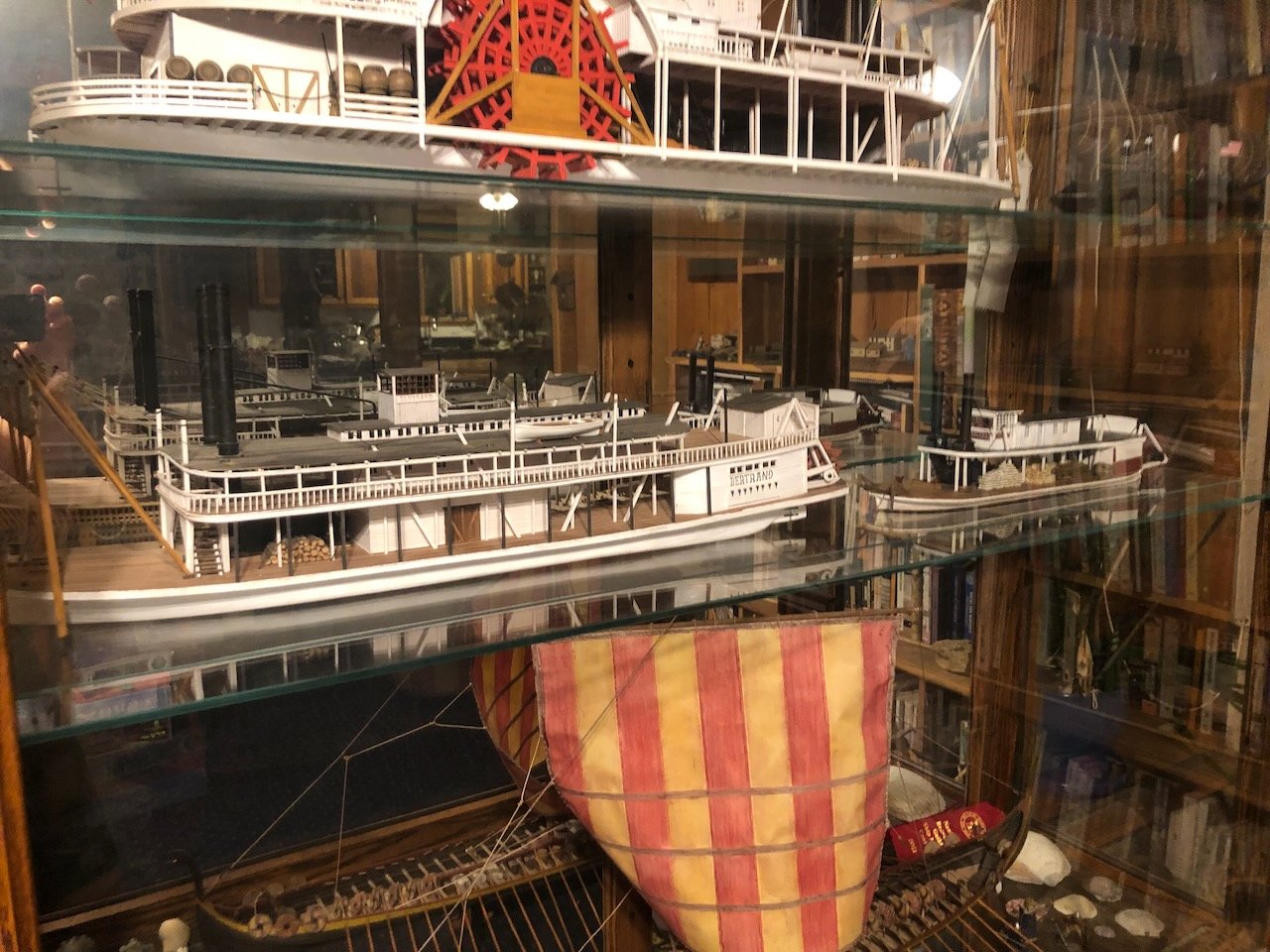
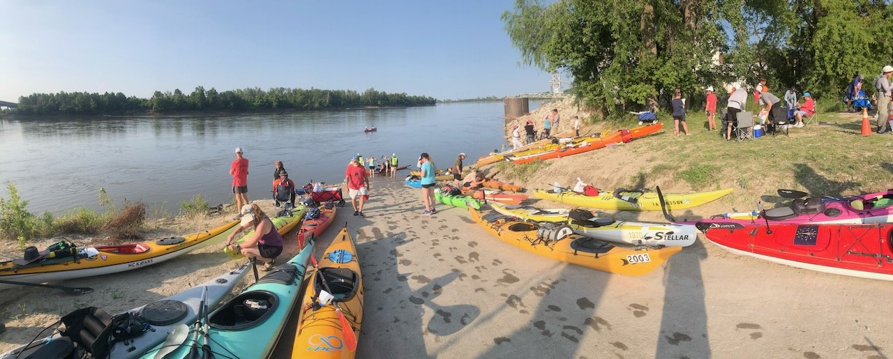
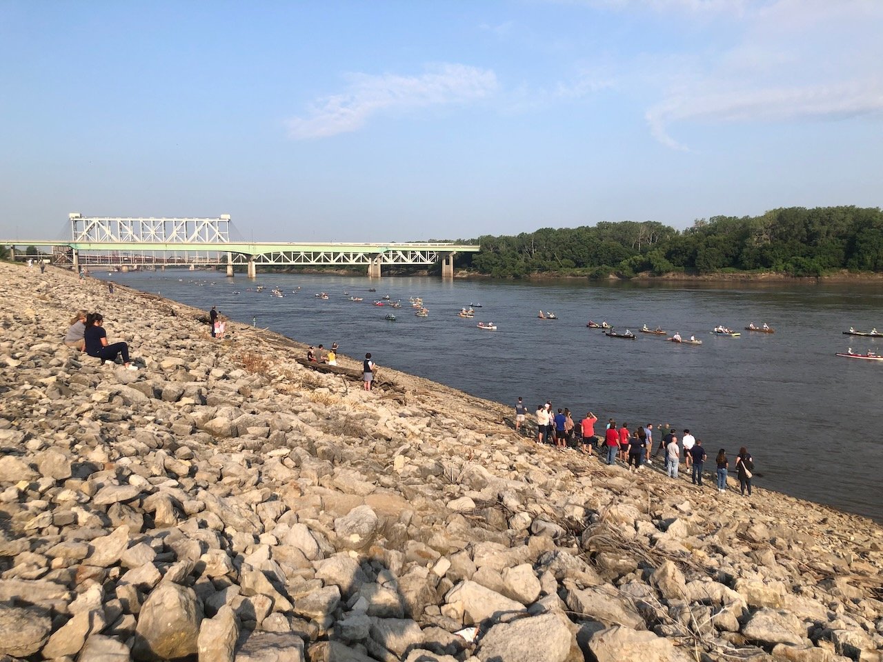
 All the kind comments are much appreciated. I haven't done anything with the johnboat yet, due to some serious time commitments lately (more on that in a moment). But I did transfer Peerless to her temporary home in my display case, next to Bertrand; since both are 1:87 scale it's a nice size comparison from a fairly "normal" Missouri River boat and the little Peerless. Arabia, on the shelf above, is actually about the size of Bertrand but is 1:64 so looks larger. The aforesaid time commitments relate to the Missouri River; we spent last week on the road with the Missouri River 340 race, an annual 340-mile cross-state paddle race on the river from Kansas City to St. Charles (near St. Louis). It's billed as the longest non-stop human-powered boat race in the world and takes incredible endurance to complete. Over 400 boats entered this year and a bit over 300 finished. We spent the week chasing the race across the state, acting as ground crew for a participating friend, and volunteering at various boat ramps where racers receive necessary support. We were also filming for a future video for our YouTube channel, a spectator's guide to following and watching the race. I spent a lot of time in the water helping boats land and launch, and offering encouragement to tired racers. If interested, you can read more about the race here. Since you're wondering, we've not done the race ourselves, though we have paddled stretches of the river on our own, but I'm working toward tackling it soon. This isn't strictly model-related but I get the most value out of projects that have a sense of history and place, and being involved with the modern Missouri River gives these steamboat models so much more context and value. So here's a few shots from the race week. A mass of paddlers shortly after race launch, coming along the Kansas City riverfront. This is a small fraction of total race participation. A major steamboat landing for the nascent city was maybe 1/2 mile upriver from here. A busy ramp servicing hundreds of boats in a few hours (replenishing food/water, answering questions, etc.) I'm in the mix somewhere in one of the bright safety vests. A nice sunset along the river, where we biked out to a more remote setting to watch and cheer on racers as dusk fell. Note the lone paddler near Mrs. Cathead; by this point in central Missouri the racing pack has spread out over many tens of miles, so paddlers are often alone for long stretches and appreciate a random cheer from the bank. Just another way to share the special place that is the Missouri River with you all. Upcoming weather is not conducive to outdoor photography (heat index well over 100ºF every day) so proper photo shoots will have to wait. Thanks for your patience!
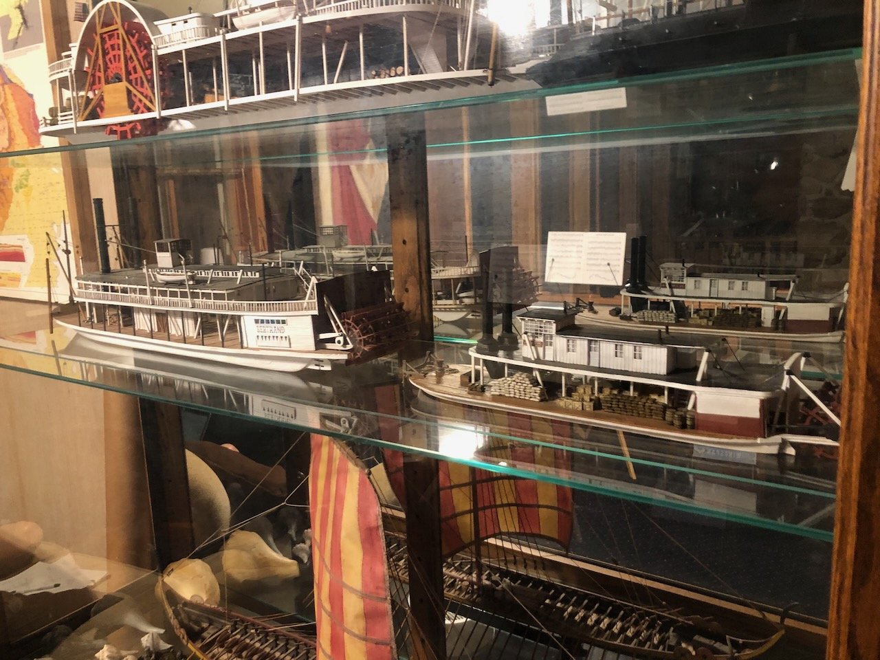

- 393 replies
-
- 15
-

-

-
Wait, the Lego Titanic doesn't come with an iceberg? Ripoff. Seriously, though, that looks loads of fun. Update looks great. Love the crisp railings and excellent tow knees. Great to have you back. As a Mac user myself, welcome aboard.
-
That is definitely a prototype just oozing charisma. It'll look great next to your barge. It'll be really fun to see how you adapt it for your needs!
-
Nice progress! Think of your pilot house as one of the details that makes the model distinctly yours. And the best advice for a hated task, like building stairs, is to just take it one step at a time.
- 158 replies
-
- 1
-

-
- chaperon
- Model Shipways
- (and 1 more)
-
Thomas, I don't seem to have any of the plans or instructions anymore. It was a long time ago, and I wasn't particularly pleased with the kit, so I likely recycled them as I had no intention of ever using them again. Sorry! I wonder if Corel would be willing to provide you with a set if you got in touch? Good luck.
- 96 replies
-
- 1
-
-
- topsail schooner
- revenue cutter
- (and 3 more)
-
Keith, wood was standard during the peak steamboat era in the mid-1800s, but just like railroads, coal took over in the late 1800s as it became more widely available as it's a more energy-dense and reliable fuel. And since Missouri had (and has) extensive coal deposits, it especially wasn't difficult to shift to coal around here. Peerless was built in 1893, so is much later than the "classic" wood-burning steamboat one tends to think of from the 1840s-1870s or so, meaning I've assumed she was a coal-burner. If you look at my mid-century boats like Arabia or Bertrand, they have stacks of wood on their decks. EDIT: as to your other question, I haven't decided on an off-topic build log. Part of me enjoys the community and the push to keep working, part of me wants to be free of the commitment.
-
Thank you all so far for the kind comments and likes. Don't forget to chime in on the johnboat question if you want. As for figures, as I briefly noted earlier, I'm not pursuing that for now but probably will in the final display context since I'll need other figures across that landscape anyway.
-
Agree with Wefalck. You can easily get a simple set from a hobby store or art shop. There are even sets made specifically for weathering models, which have a broader range of certain colors in the black/grey/brown/rust spectrum. These are nice since most art sets tend to have colors you don't need much, like purple. You can apply then gently with a brush, swab, or even finger tip. I'd recommend practicing on scrap surfaces first since pastels don't always come off easily. But they're wonderful for adding light layers of grime, rust, and other textures.
-
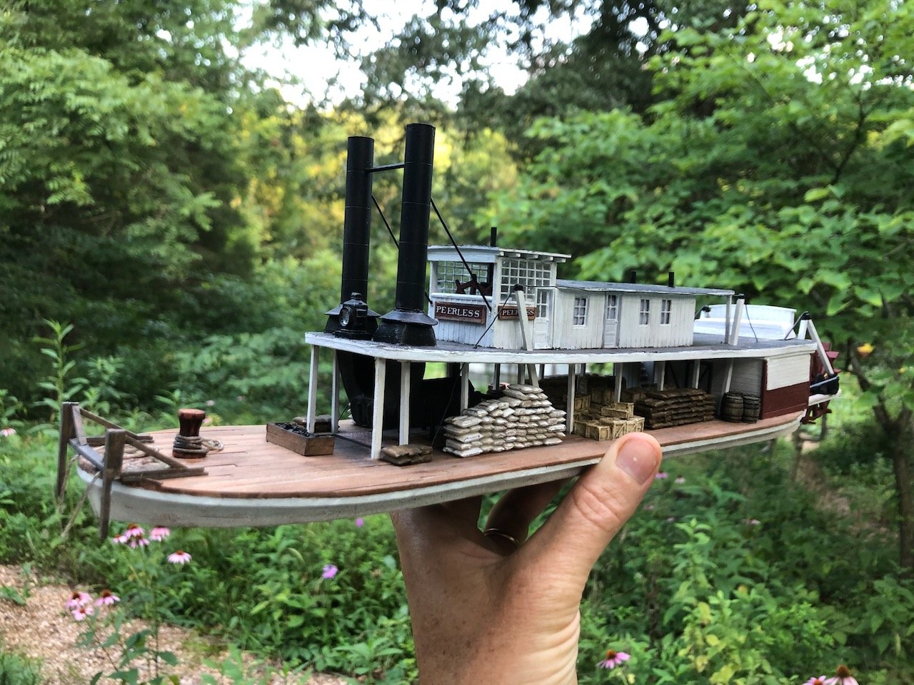
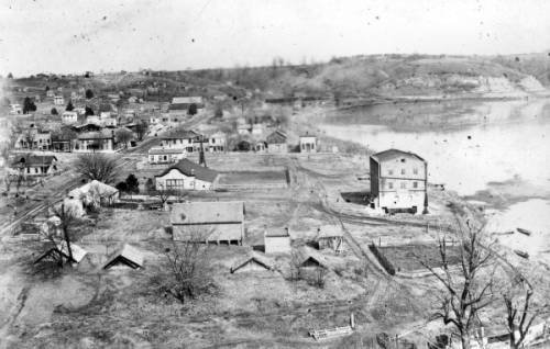
And three overall shots: I don't have sufficient words for how much all of your interest and support has meant over the last year or so as I work through this build. I made a lot of mistakes along the way and you all did a great job gently pushing me to be better. I thought this was going to be a relatively easy project given my past steamboat scratch builds, but it was very different than any of the others and once again I had to learn new skills and figure out new things. My heartfelt thanks for every like, comment, message, and so on. As for what's next, which I promised to answer. I'll taking a bit of a break from ship-building to work on a ~12' long modular diorama depicting Peerless's home port of Rocheport on the Missouri River, arranged as a model railroad setting that may be expanded into an operational Missouri, Kansas, & Texas layout depicting that railroad's operations along the Missouri River in this area ca. 1900. Whether I go that far or stop with the Rocheport bit, Peerless will have pride of place on the foreground river with the railroad tracks clinging to the limestone bluffs soaring 300' over the river. Here are a few historic photos from the ~1900 period to give you a sense of the landscape I'll be recreating. All photos are public domain, from the State Historical Society of Missouri digital collections. A different steamer tied up at the Rocheport waterfront with river bluffs in the background: MK&T passenger train along the river near Rocheport: Another view of river bluffs with the railroad wedged between water and bedrock: Rocheport town and riverfront, bluffs in background, railroad at left: I was a model railroader long before I got swept up in wooden ship building, and that old love has been resurfacing over the past few years, so I'm going to give it another go. If all goes well I may end up building yet another Missouri River vessel anyway, because there's this photo of an amazing little ferry that operated at Rocheport: Isn't she just darling? And look at those covered wagons. This view spans so many eras in American history. Thanks again, hopefully I'll have another photo shoot to share in a few weeks.
- 393 replies
-
- 24
-
-
-

-
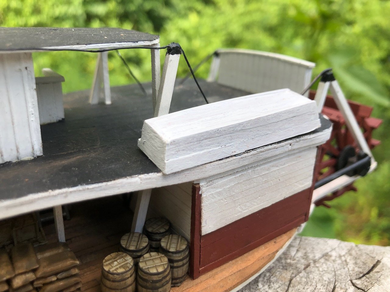
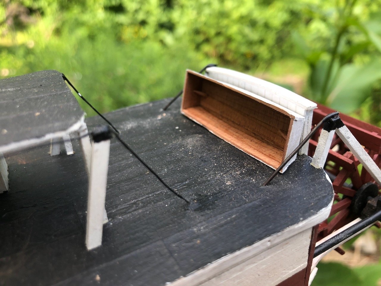
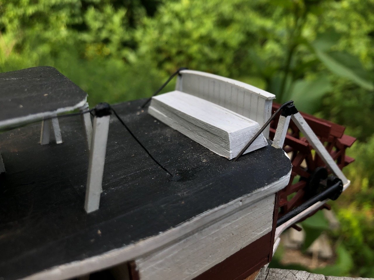
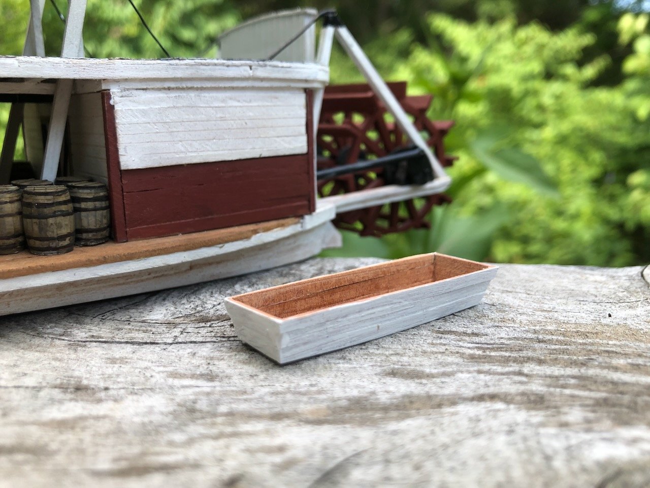
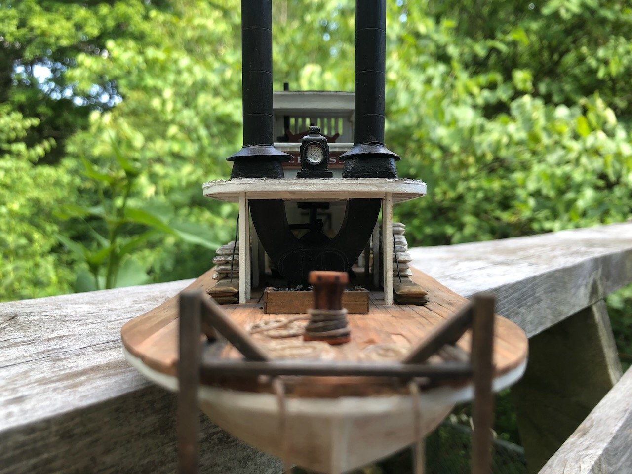
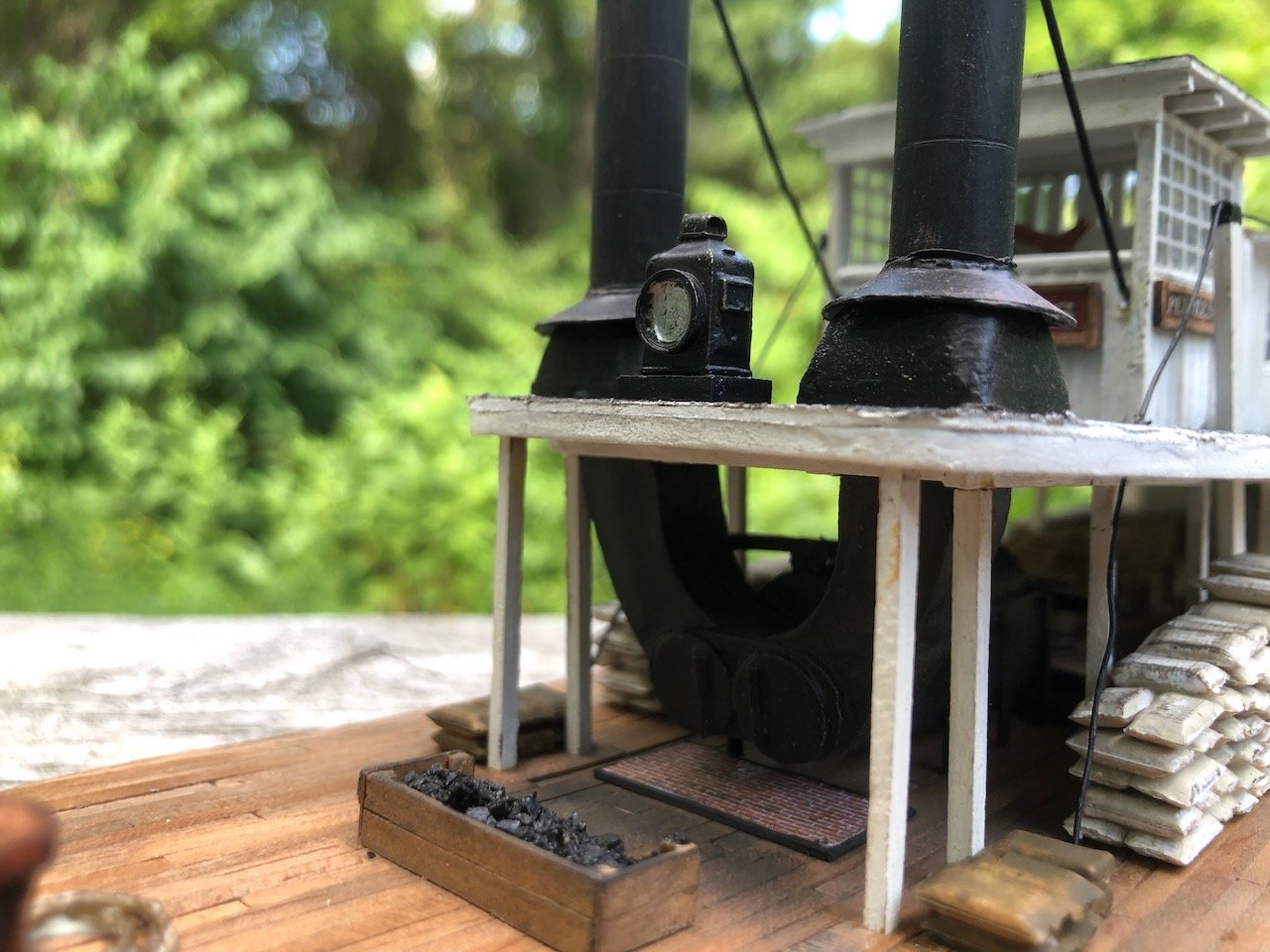
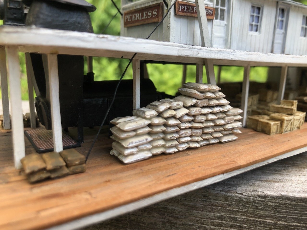
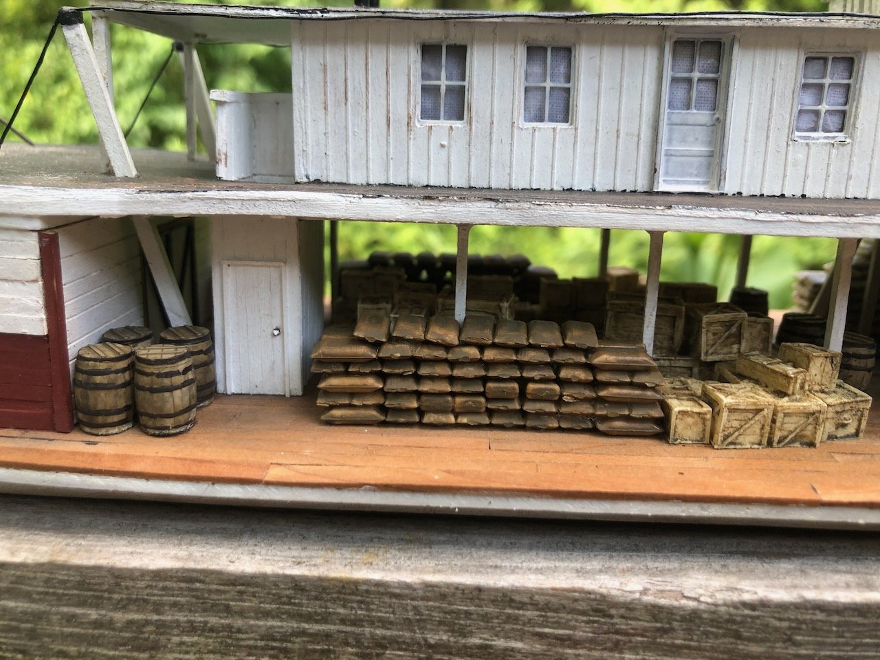
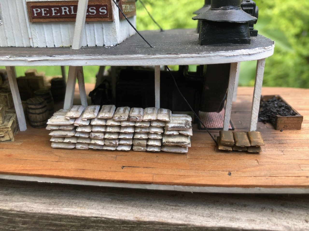
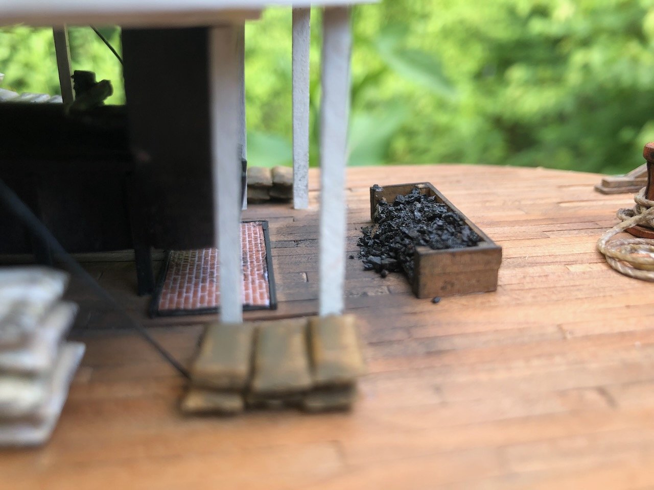
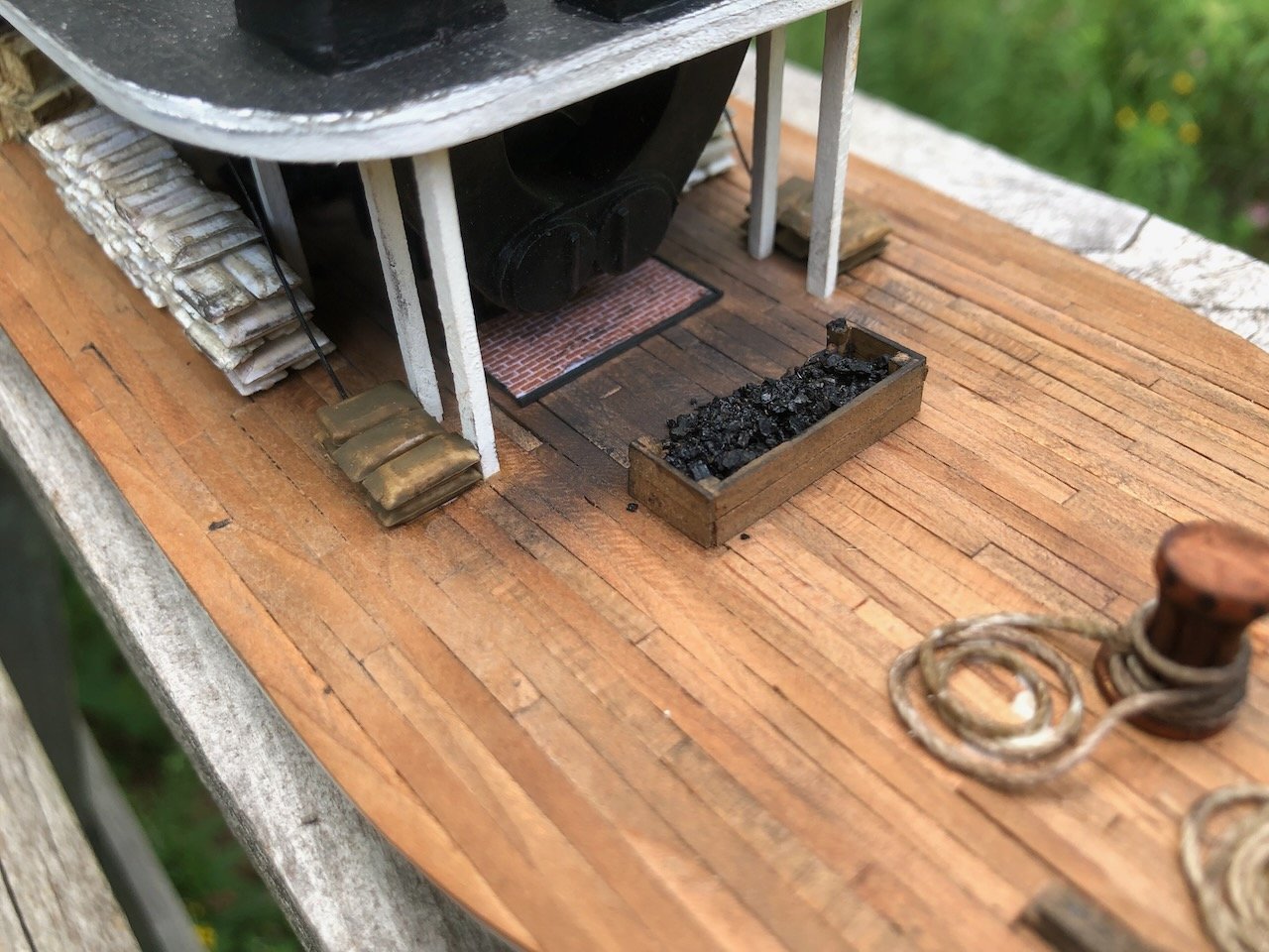
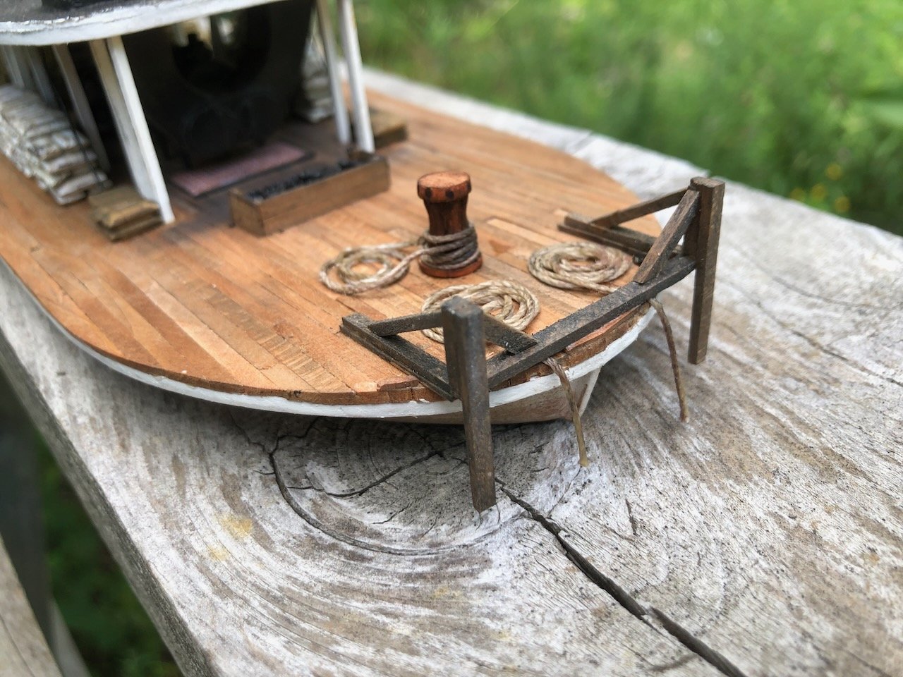
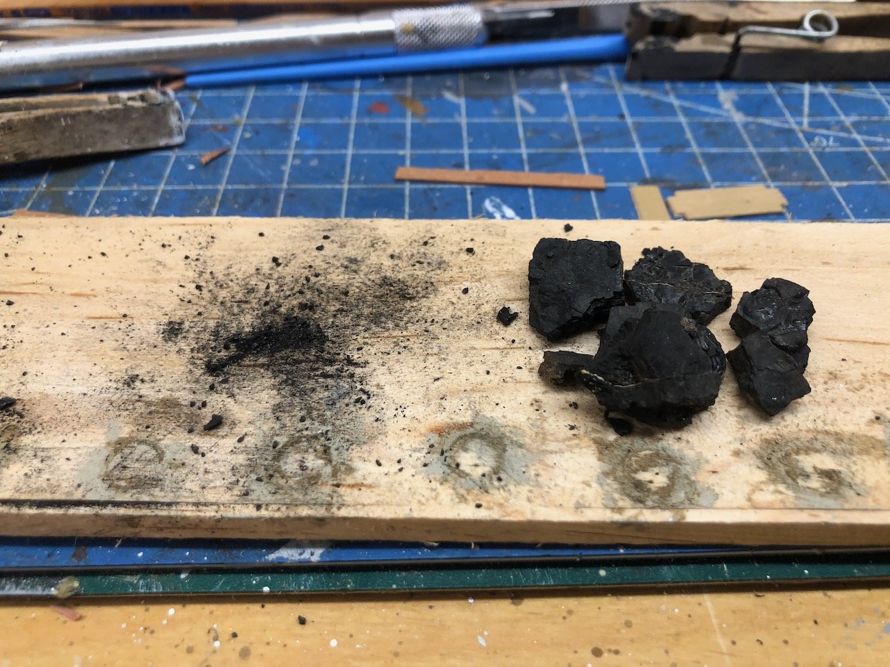
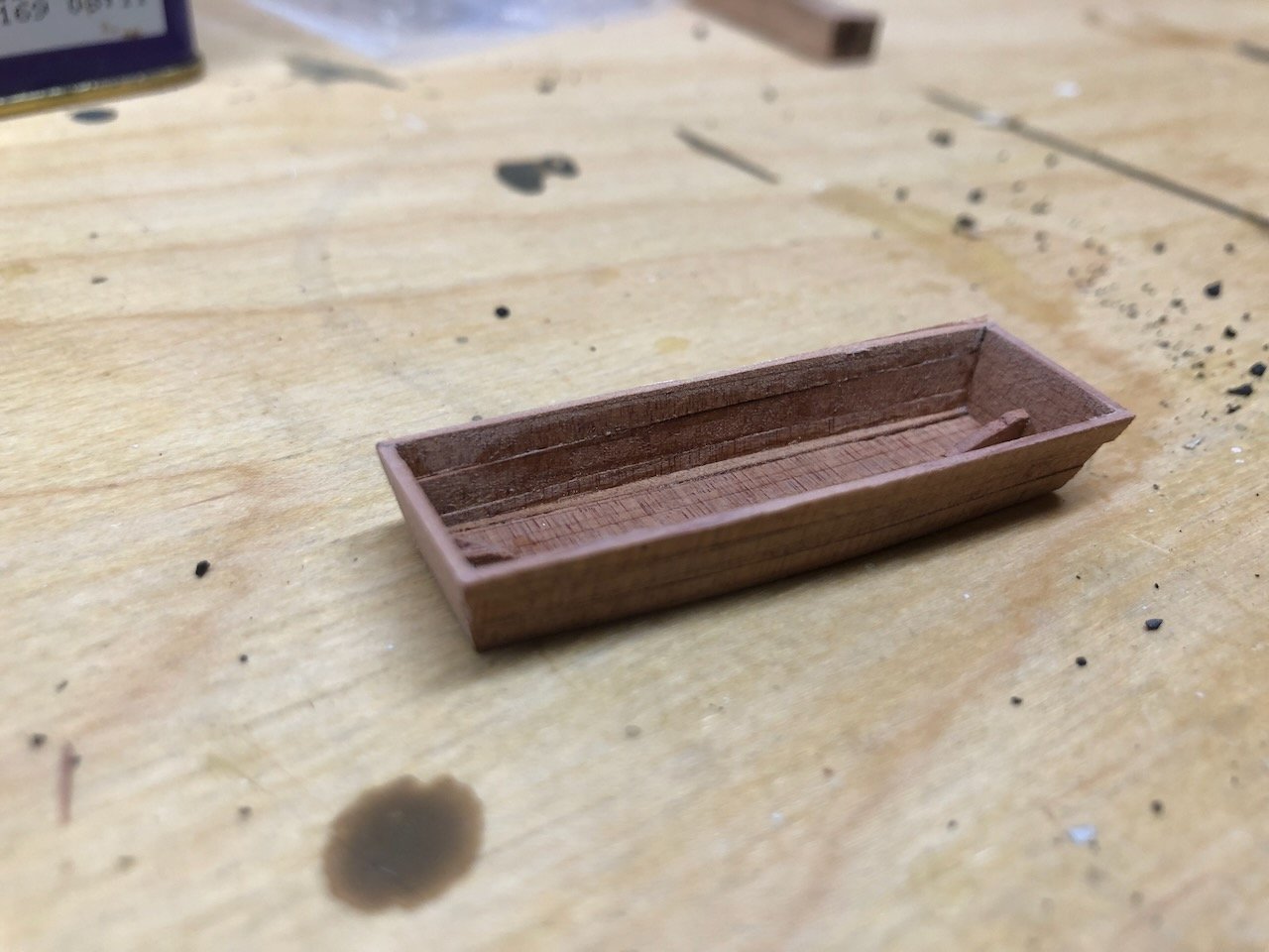
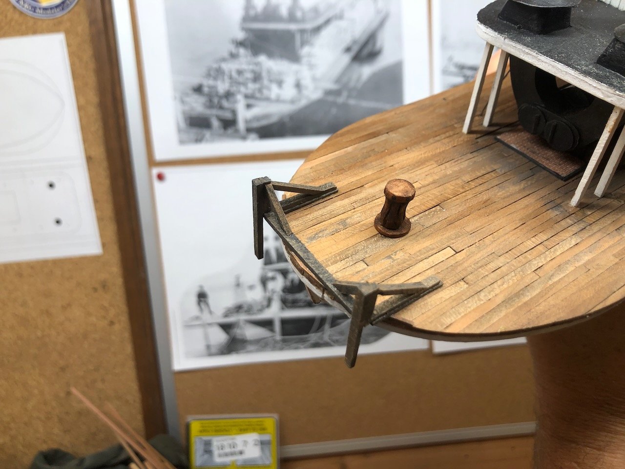
Brian, all those detail parts were ordered from Walthers, the big model railroad retailer. And here we go with the final detail tour. First, closeup views of various sacks, crates, and barrels. My inspirations were shots like these two, showing long stacks of sacks running along the guards: You can't see behind the sacks in those shots, but I just decided that I wanted to put all the crates in the interior part of the main deck When I do final photography I'll set up a light to shine in among the shadowed crate stacks to show them off better. I aligned them to leave a central walking aisle all the way down the deck, figuring that'd be wanted for a variety of reasons. Sharp eyes will have noticed a new detail in that last photo. Harkening back to a long-ago discussion on this log, I decided that the "forecastle" area was too empty and decided to add a little free-lanced coal bunker. There's no evidence for this, but neither is there any proving its absence, and I like it as a detail. In my theory, the coal is brought on board in sacks (the two small stacks of brown sacks on either side of the firebox) and dumped into this open bunker to allow for easy stoking into the firebox. You'll notice that I used black pastel to darken the whole work area between the bunker and the firebox; coal dust gets everywhere. Speaking of which, the coal in that bunker is my pièce de résistance of locally sourced material: it was harvested from a coal bank on my rural property. I collected some small pieces and manually crushed them to get a range of appropriate sizes, then glued down a mound of the stuff within the bunker. Here it is in raw form as I crush it: This particular coal seam was mined in my county from at least the 1870s through the 1970s. So seeing it here on Peerless ca. 1900 is pretty darned realistic. The other surprise detail was some sort of utility boat. Vessels like this didn't carry lifeboats, per se, but they did have one or more working boats for all sorts of chores. A variety of types can be seen on various photos, from narrow-ended yawls (see the especially fancy one on an earlier photo shared above) to chunky boats that look pretty similar to Ozark johnboats. These latter were super-simple vessels that any hill-country carpenter could knock together for use on Ozark rivers; they needed to be strong and shallow but not particularly streamlined. Many were all but small barges. Here are a couple articles on them with some photos and drawings: article 1 and article 2. I felt that a form of johnboat would be just right for Peerless, so set about making a rough version from thin scrap wood (in this case, Eastern Red Cedar, again cut and milled here on-farm). It's especially chunky even by johnboat standards but it gets the idea across. The question is how to display it. Various photos show a boat turned upside down on the port side like this: Upside down on the after boiler deck like this: Or turned on its side in the same location like this: You'll notice I haven't finished the interior yet with ribs and so on. That's because I haven't decided how to display it. Two of these three options mean I don't need to finish the interior, while the other does. I can't see any sign of proper davits in any photos, so they must have just manhandled their boats up there with a few strong men and ropes. Once again fitting the rough-and-tumble life of rivermen out here. So I'd be curious on thoughts about which display method to use. I have a personal preference but won't unveil it before getting some feedback. A final detail involved making some rope coils and installing them at the bow. Oh, and I almost forgot the railroad headlight, which you can also see in the photos below. Here's another view of that: Other than the final johnboat decision, I do believe that's all I'm going to do on this model in the near future. At some point I'll probably add figures but am not going to go down that road for now. In the next few weeks I hope to set up a proper photo shoot, including maybe out along the Missouri River. This post has gotten really long, so in one more subsequent post I'll share a few quick full-vessel shots taken this evening.
- 393 replies
-
- 18
-
-
-
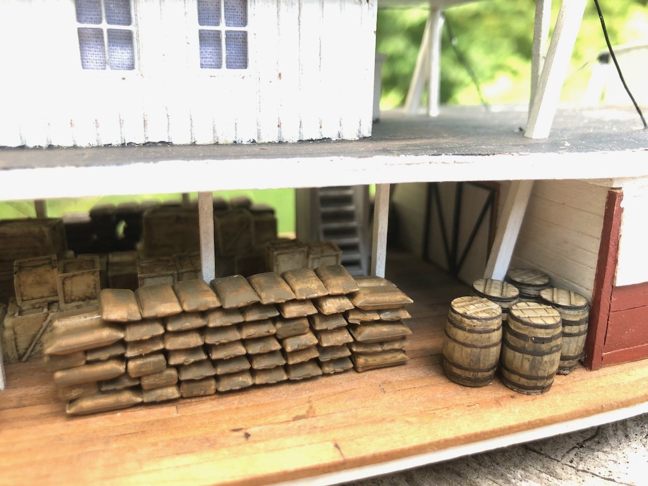
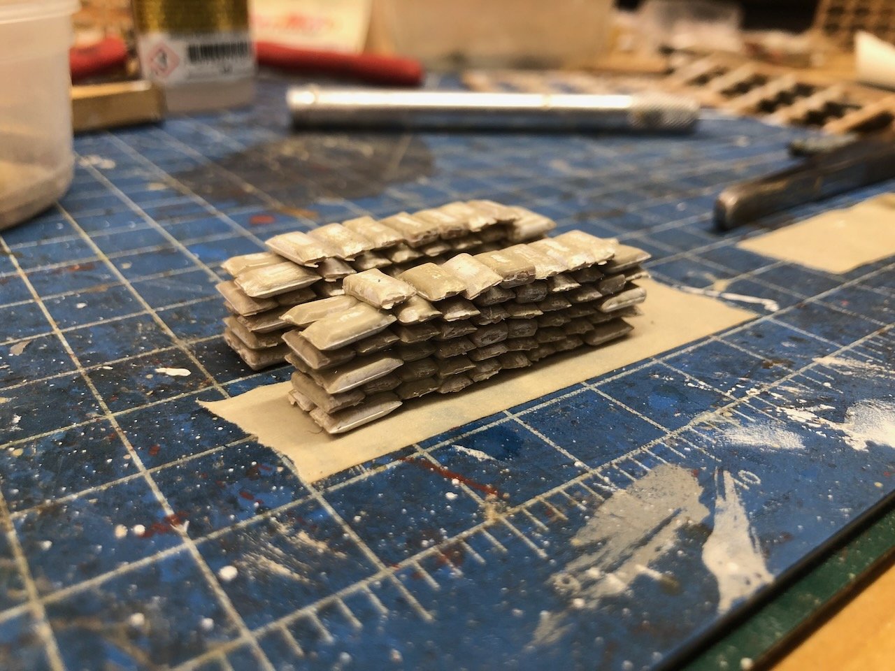
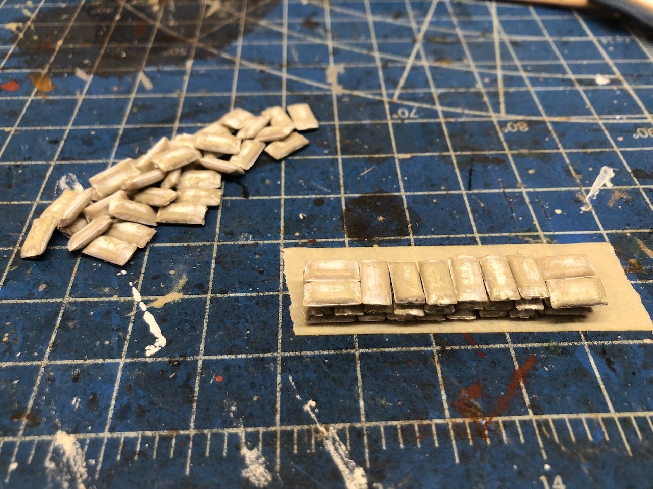
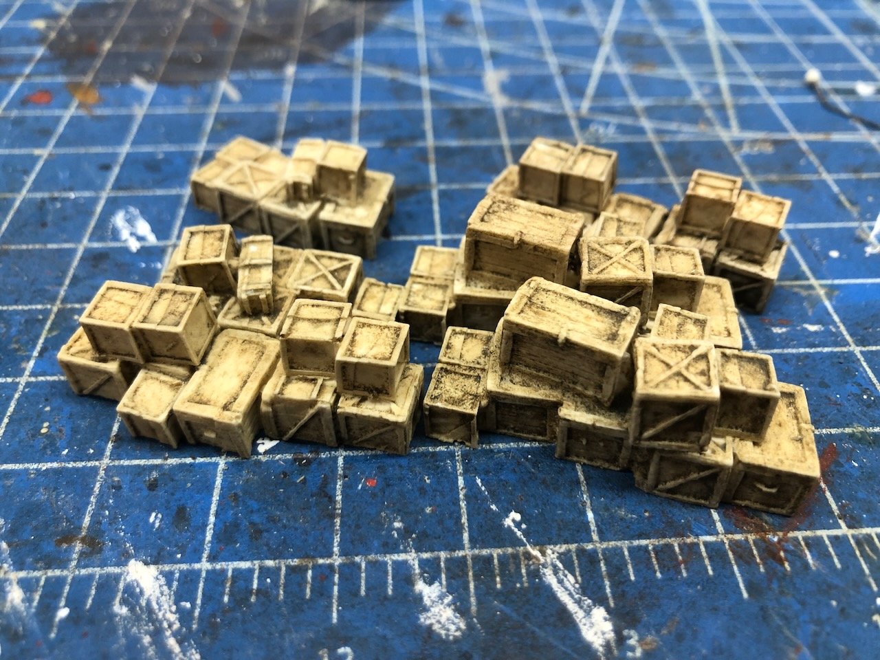
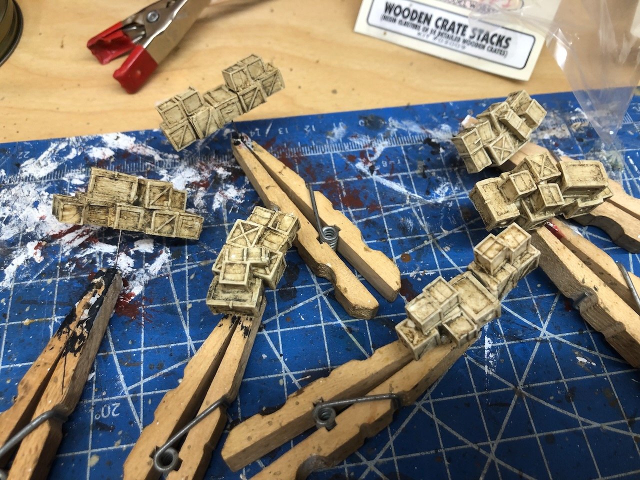
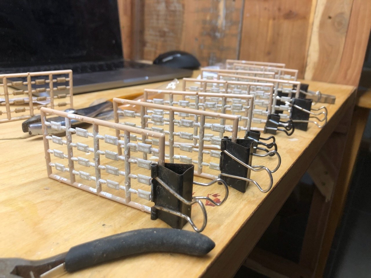
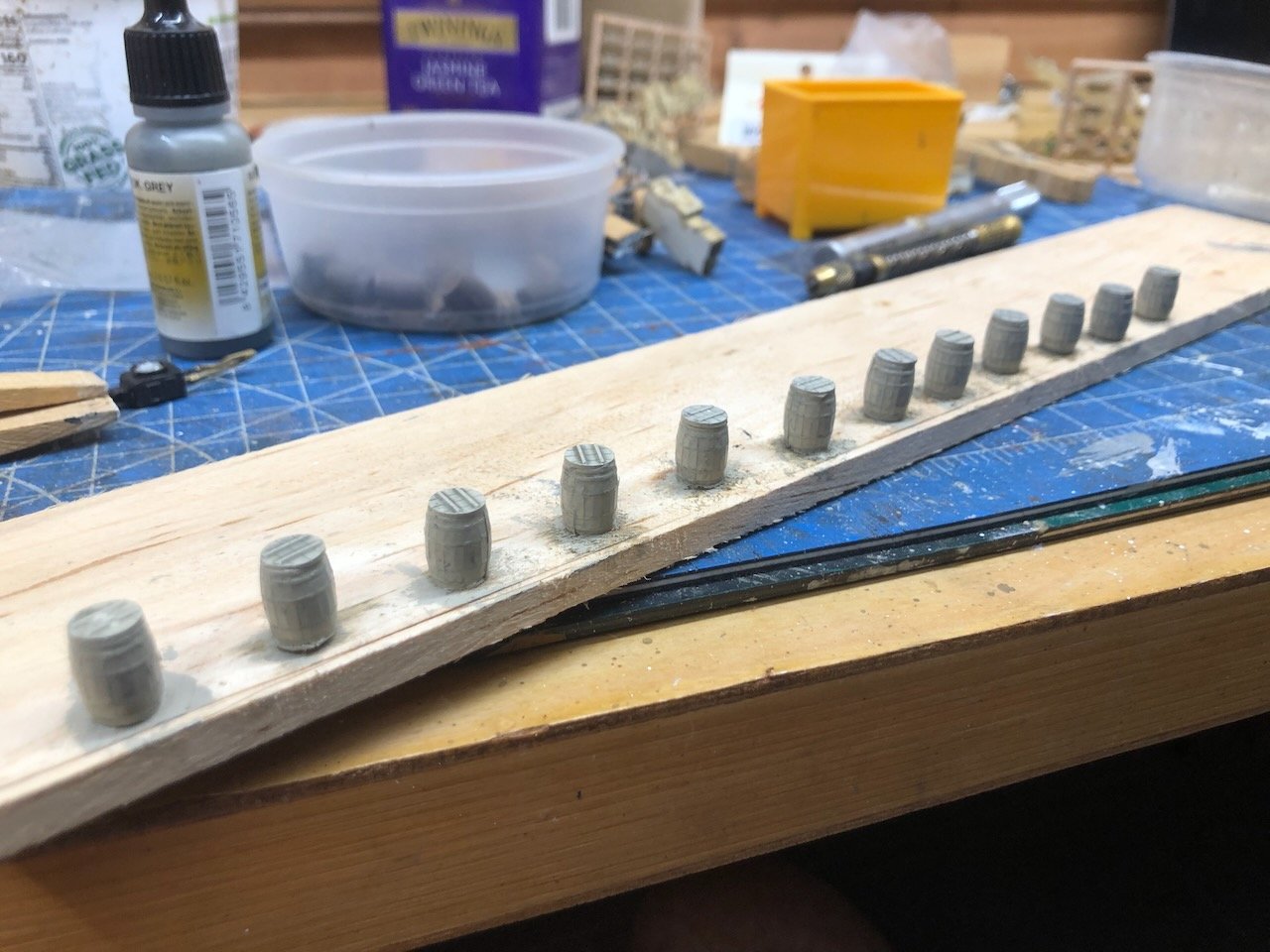
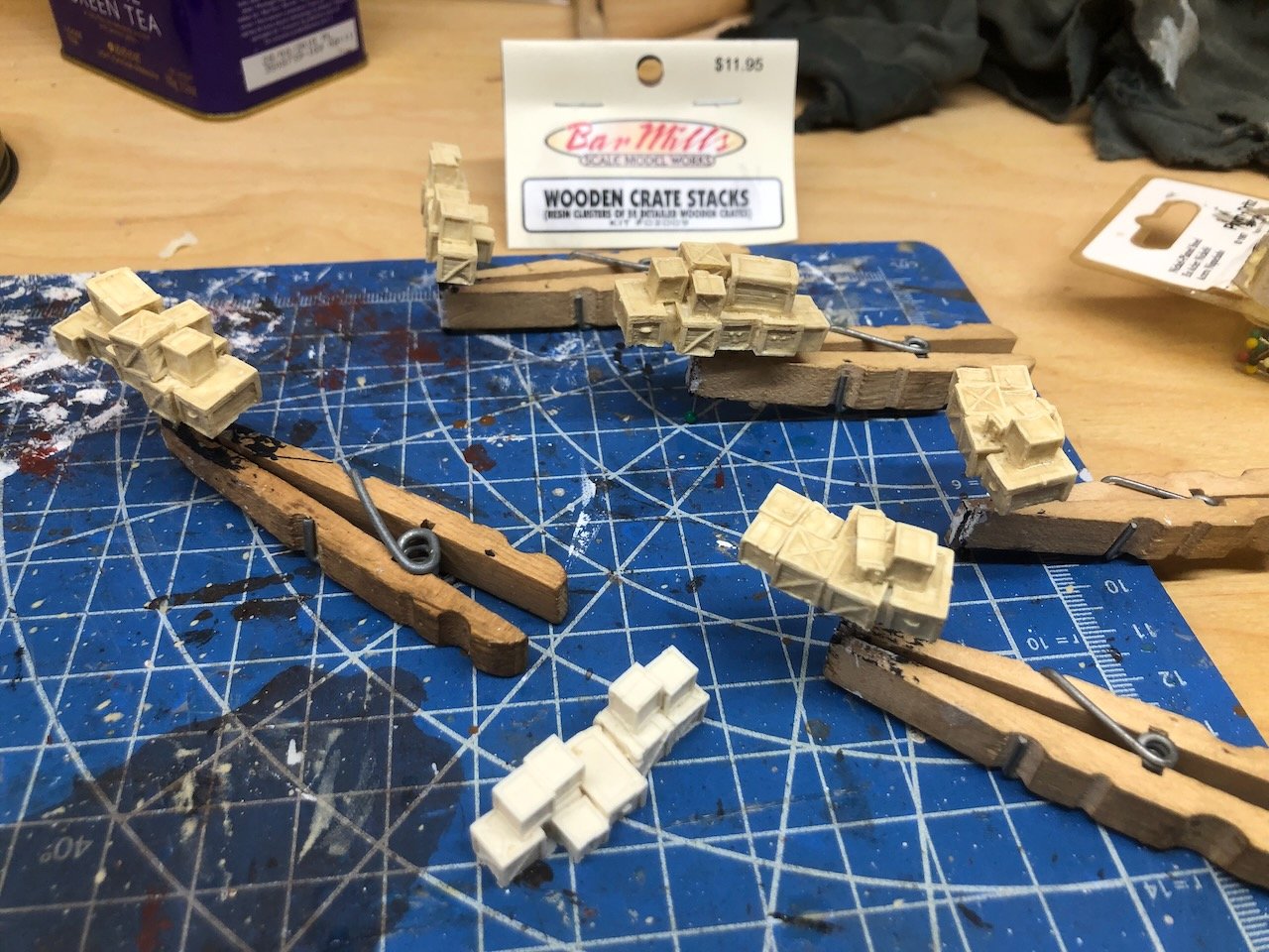
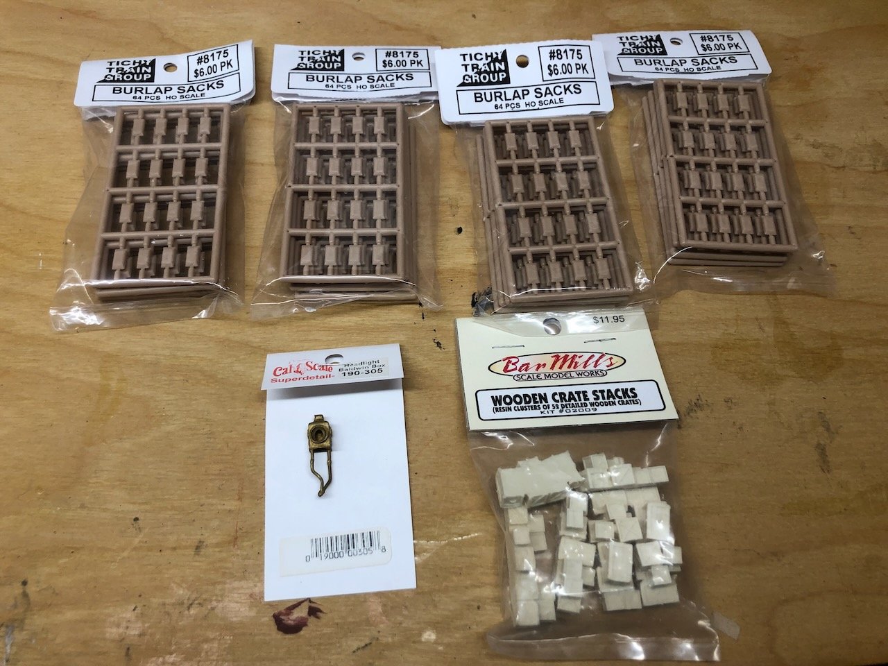
And on to the final detailing. I ordered some items that I either couldn't or wouldn't make by hand. This is where working in 1:87 comes in super-handy, since the HO model railroading world is chock full of useful detail parts. Here's my order: 252 burlap sacks, a set of resin-casting crate stacks, and a steam locomotive headlight that's extremely similar to the one featured on Peerless. But the real fun came in painting and weathering these items. For the sacks, I divided them into two sets and painted one whitish (like a flour sack) and the other a darker brown (like a generic burlap sack). I did three layers of paint washes followed by some light pastels to build up a complex weathered look. When I liked the individual appearance, I built them into long stacks by starting with double-sided tape (to hold the base together) and then using glue to hold the pile together. When complete, the stacks came off the tape nicely as a coherent whole. I used a similar approach for the crate stacks, with multiple paint washes building up complexity and then a final dusting of pastels. The first photo below shows the initial step from raw resin to coloration, and the second and third photos show the final result. I drilled and drove brass pins into the base of each stack so it could be held from below, allowing full painting without handling. I forgot to take any photos of working with the headlight, but I painted it black, used wood glue to fill in the lens opening (giving it a nice subtle rounding as the liquid dried), then painted the "lens" silver. You'll see it installed in the next post. Finally, I grabbed a bunch of barrels I had left over from other projects and used the same approach as all the other stuff. I took one photo partway through coloration and then forgot to keep up. To work with these easily, I used a similar method to the crates, drilling a series of small holes through a plank of scrap wood, then driving small brass pins up from underneath. Each barrel (also pre-drilled through the bottom) sits on a pin that holds it snugly in place while I paint and weather. Those are all the in-progress photos I took. In the next post I'll share the final look of all these details as they're installed on the model, along with two additional surprises that I hand-built instead of buying (I also failed to photograph these in progress).
- 393 replies
-
- 18
-
-
-
No worries! Nothing wrong with exercising the brain by thinking out loud. Who knows how many other people might have had the same question and have now had it answered because you were willing to ask it?
-
Out of curiosity, why couldn't the helper vessel tie on with bollards on the bow and simply go into reverse, rather than towing? A longer discussion of this should probably occur over in your log, though.
-
Keith, good question. To the best of my knowledge, towing was very briefly attempted in the early days of steamboating and generally abandoned quickly. Sidewheelers could have towed, but it was just too hard to control a heavy load dangling off the back end, on curving and narrow rivers, for vessels whose steering was already somewhat limited. Pushing also meant you could naturally monitor the behavior of your "tow", rather than having to constantly look both ahead and behind you from the pilot house. Think of how most people prefer to push a shopping cart rather than pull one behind them when navigating narrow and crowded grocery store aisles (same for a baby carriage or stroller). The phrase "towboat" managed to hang on somehow. In fairness, even modern maritime helper vessels are called "tugboats" although their primary action is to push large ships.
- 393 replies
-
- 11
-
-
-
A man after my own heart...
-
Hi Thomas, it's possible I still have the plans tucked away somewhere and can look when I get a chance. If you don't see a response in a couple days, please post again to remind me.
- 96 replies
-
- 1
-
-
- topsail schooner
- revenue cutter
- (and 3 more)
-
A few small round files are highly useful for almost any modeling, and certainly help with getting axles to fit properly!
-
Looks nice! What approach did you end up using to run it through the table saw?
-
This has been a real treat to follow, so much to learn from, admire, and enjoy. A fitting addition to a really attractive display space.
- 282 replies
-
- 2
-
-
-
- Bluenose
- Model Shipways
- (and 1 more)
-
Tony, I realized that for clarity I should explain that I've never done precisely what you're proposing. I use a 30' bandsaw mill to reduce full-size logs down to lumber-scale planks (e.g., 3/4" thick and 4-6" wide by 6-10' long). Those that I don't use for full-scale use get cut down further with a chop saw, band saw, or other tools and then run through a Byrnes saw to make model-scale lumber. I've never pre-prepped a smaller-scale log the way you're proposing (direct to table saw), though I've read quite a few discussions about other people doing it and am drawing on that background as well as my own general woodworking/milling/logging experience to give advice. Just wanted to ensure the proper level of salt on my thoughts. I'm sure you'll come up with a great way that's comfortable to you and I'll look forward to learning from your experience!
-
Don't get too ahead of yourselves, folks, the planned detailing will definitely change her appearance and she's not "done" yet. But I appreciate the, well, appreciation nonetheless. As for what's next, I'll leave that until she's truly done.
-
Oh man, this looks absolutely amazing as a project. Given the intended waterline design and hints at a broader project, I'm guessing this is intended as part of a diorama/display? How did you settle on the scale you're using? It isn't a standard model railroad scale, which would have been my first guess for something intended for a broader setting than a lone model.
-
Tony, for what it's worth, over the last few years I've shifted toward milling my own wood for model projects (wood that I've harvested myself), and so far I've found myself astounded by how much model-scale lumber comes out of even a smaller log. My sense of scale is calibrated to firewood and construction-scale lumber (I normally build furniture, sheds, barns, etc. with the lumber I mill here on-farm) and even with lots of loss to milling kerf, I have more model wood than I could ever use just from a couple moderate-sized trees. Granted yours is smaller diameter than anything I've done but even a series of 1' long, 2"x2" blanks will produce quite a bit of thin wood. I guess it depends on what size and type of model projects you're contemplating using this for. My personal take would be to not worry so much about the minor loss of running a flat edge along one side. You don't have to cut the log in half, just take off enough of one side for a flat stable edge for further milling, essentially what you'd have to take off anyway to get rid of the bark and outer edge. But you also know your equipment and skill set best, so I don't mean to tell you what to do.
-
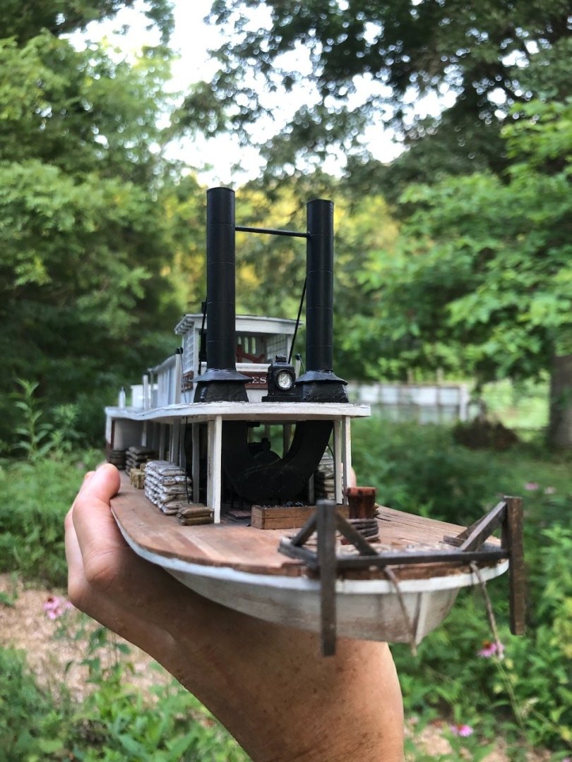
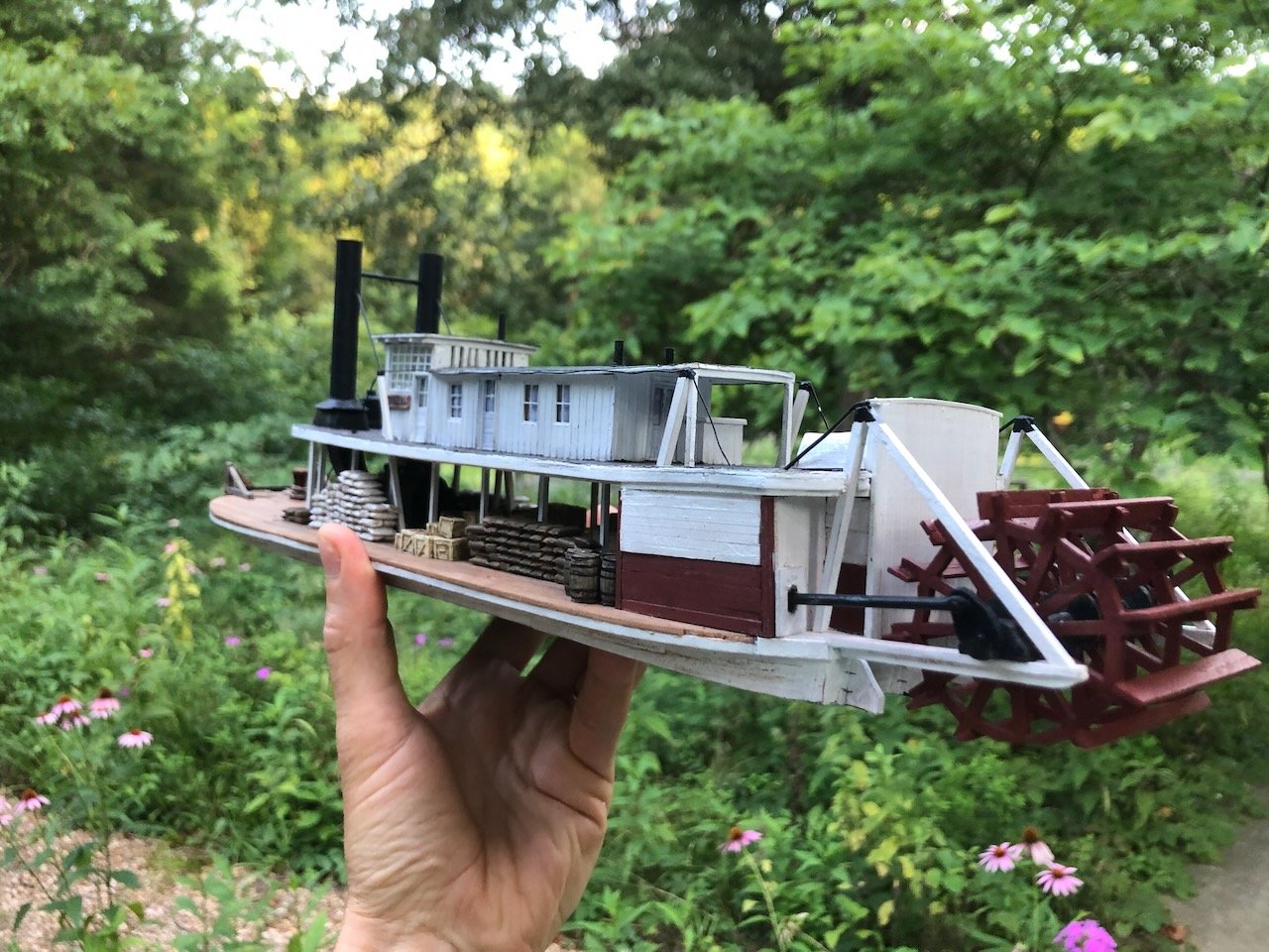
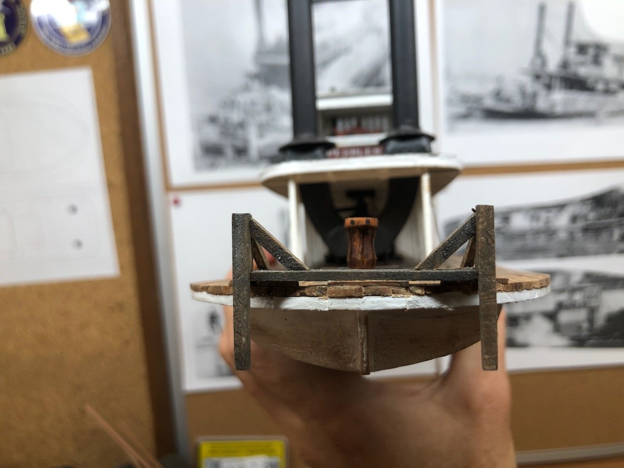
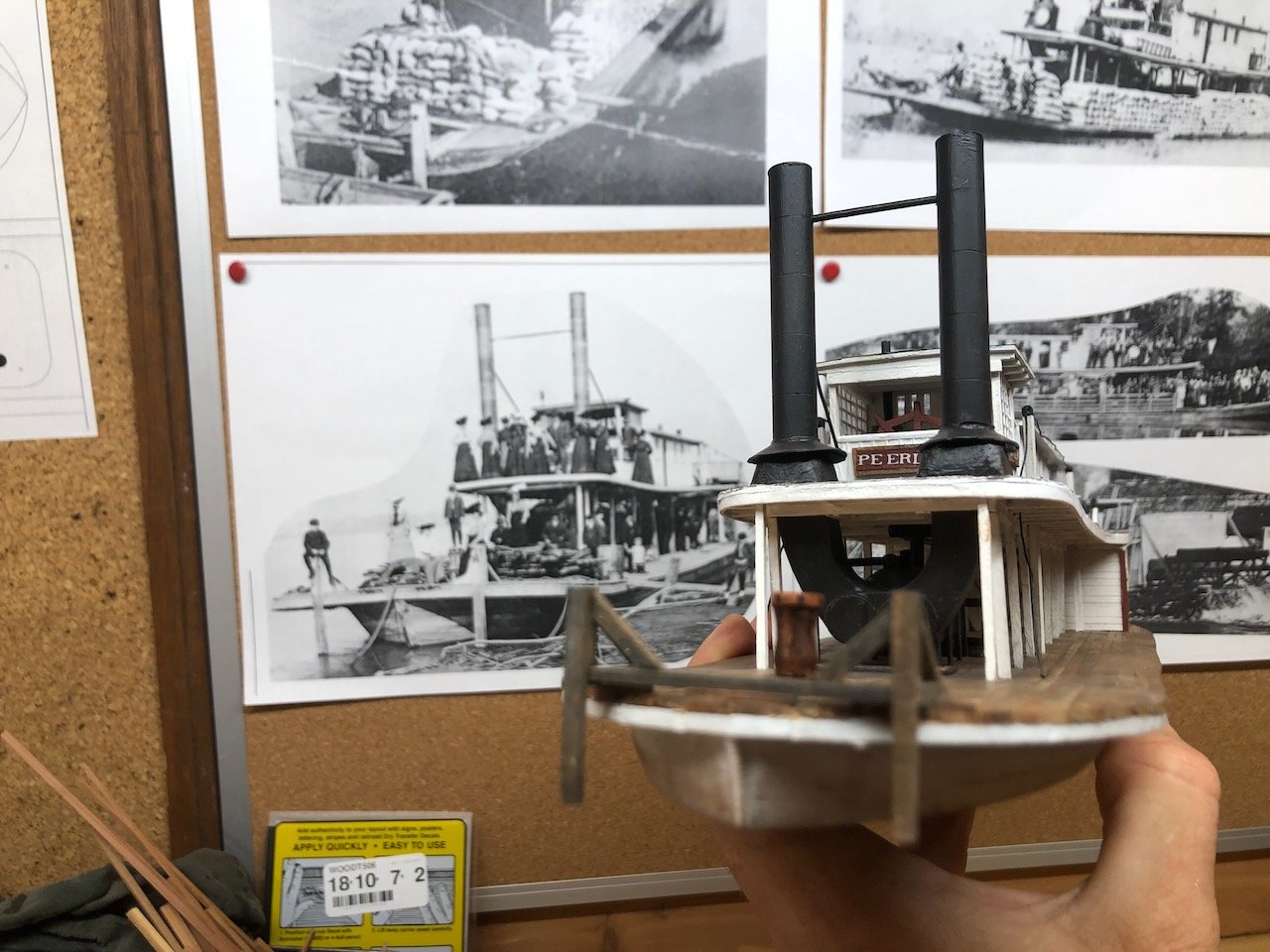
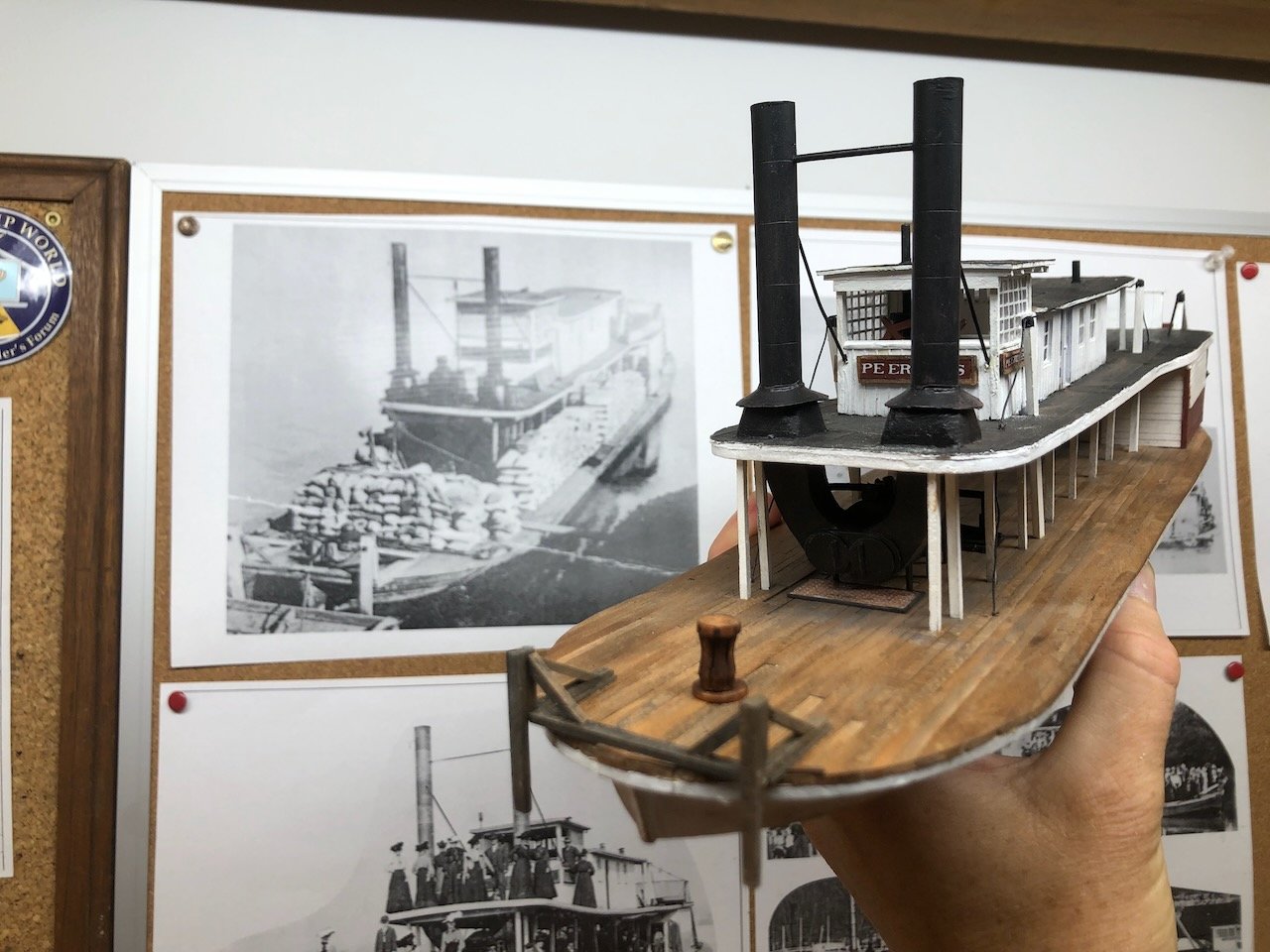
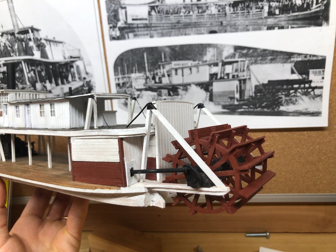
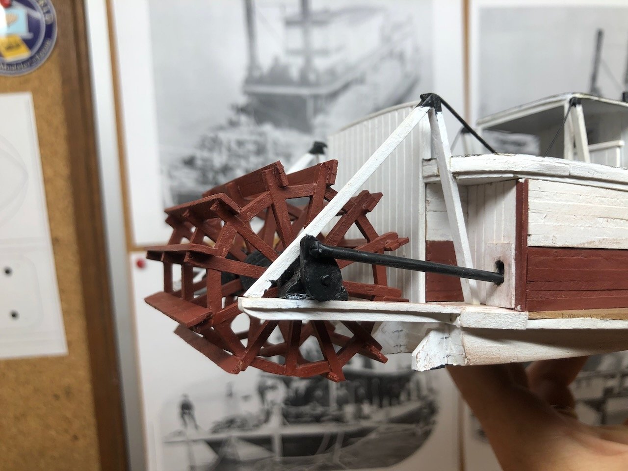
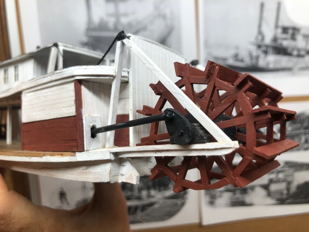
Keith, I may be "young", but I grew up listening classic rock. Yanking this thread back on topic, you hard-driving taskmasters got your way. I made some thin covers for the pitman arm openings that better mimic the real vessel, and replaced the wooden beams with round pipes. Here's the result from each side: Also, here are a couple more shots of the bow: I think this completes the model itself. Only the addition of some superficial details remain. Here's some shots posed against comparable imagery. Once my detail parts order arrives, I'll work on adding some fun final touches. Really getting there now!
- 393 replies
-
- 19
-
-
