


Cathead
-
Posts
3,532 -
Joined
-
Last visited
Content Type
Profiles
Forums
Gallery
Events
Everything posted by Cathead
-
 That's adorable! Great job on a creative way to do the upswept stern, that's always been hard for me to get right. And I've broken off more than my fair share of wheel supports, so I love the solid plywood version.
- 732 replies
-
- 5
-

-

-
- Lula
- sternwheeler
- (and 1 more)
-
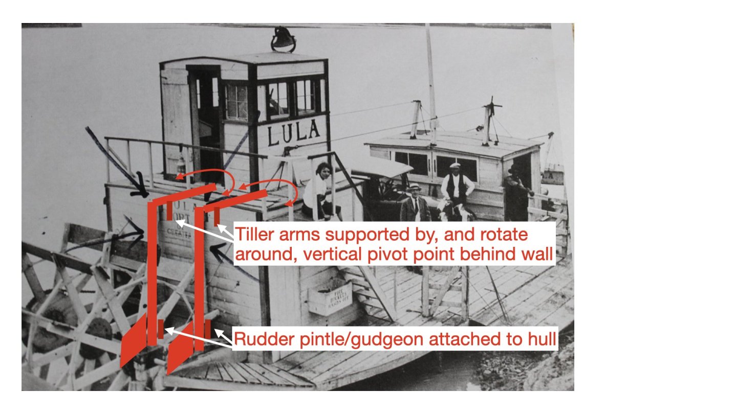
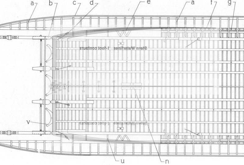
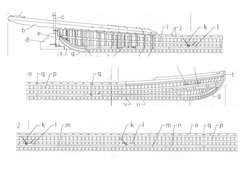
Wefalck, you just made me realize the flaw in my suggested arrangement: it's not physically possible for the rudders to be hinged against the hull while the tiller arms rotate on a vertical pivot point set a foot or so further forward, because even an offset of six inches from the rudder hinges to the pivot point would result in too much bending of the tiller arm. All the rotational axes have to be stacked vertically. So yes, either the rudder hinges are set a bit further forward (under the tiller pivots), or the rudder posts have to be hinged against the back wall. Given that many sternwheelers had sterns that curved sharply forward (see again the drawings of Bertrand) it's at least conceivable that the rudder hinges are set forward enough (a bit beneath the stern's overhang) to be directly under a pivot point mounted up behind the engine room wall. It's also pretty conceivable that the rudder posts are (or could be) hinged against the back wall; just because we can't see them doesn't mean they can't be there!
- 732 replies
-
- 5
-
-
-
- Lula
- sternwheeler
- (and 1 more)
-
Not really, look at the drawings of Bertrand I posted earlier. You'll see that the wheel supports end just after the axle housing, as they do on Lula.
- 732 replies
-
- 5
-
-
-
- Lula
- sternwheeler
- (and 1 more)
-
OK, here's a rough sketch of what I'm proposing. The tiller arms would be controlled by various blocks running tiller ropes up to the wheel in the pilot house. They might even be slaved together with a rod connecting them. It would be easy to arrange the ropes such that the wheel's turning translates into the correct motion of the tiller arms; that's how all steamboats worked.
- 732 replies
-
- 8
-
-
-
- Lula
- sternwheeler
- (and 1 more)
-
Again, my alternate guess is that there's a pivot point supporting the tiller arms, just inside the engine room wall where you can't see it. The rudders themselves would have normal gudgeon/pintle attachments to the hull, and the rudder posts themselves are freestanding but supported by their strong connection to the tiller arms, which are supported by a vertical pivot point nearby. The wall openings don't have to be very big because the tiller arms are barely moving there; all the broader arc of movement happens within the engine room along the far extension of the tiller arms. Especially if the pivot point is essentially just behind the wall. To me it makes perfect sense. I can make up a rough drawing if you're having trouble envisioning what I'm saying.
- 732 replies
-
- 5
-
-
-
- Lula
- sternwheeler
- (and 1 more)
-
Keith, thinking about steamboats is more fun than the work I'm supposed to be doing, so... Wefalck raises a question I hadn't thought through, which is how the tiller arms are supported in this setup? Are there swiveling hinges/pintles attaching the long rudder posts to the stern wall of the engine room (can't see them in the image due to shadows but can't prove they're not there either)? Or are the tiller arms mounted on a pivot point of some kind just inside the engine room wall? On "normal" steamboats this wouldn't be an issue because the shorter rudder posts would be self-supporting and the tiller arms just extend out from them, like a normal tiller on a sailing vessel. But when those thin posts go up what looks like 7-8', there ends up being a lot more torque at the top and it seems like there would have to be a higher hinge/pintle on the post or a pivot on the arm or else the tops of the posts would twist right off.
- 732 replies
-
- 4
-
-
-
- Lula
- sternwheeler
- (and 1 more)
-
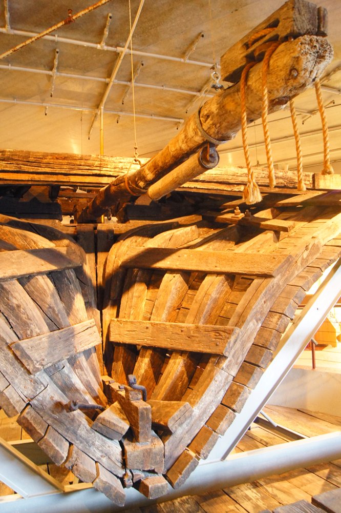
Great to see the sawdust begin! As to your question, to me those do indeed look like the rudder posts. As to why they're elevated up there, my best guess is that the compact nature of the superstructure meant that it was simpler to do this than run control lines lower down. On a typical riverboat of the kind I'm familiar with, the vertical rudder posts connect to horizontal tiller arms to which control lines were run from the pilot house using various blocks. Those tiller arms took up a fair amount of horizontal space, which doesn't matter on a large vessel, but certainly would on something as small as Lula. Here are a few examples. On Arabia, a sidewheeler with a single rudder, you can clearly see the long tiller arm requiring a lot of swiveling space, as well as the block linking the tiller arm to the pilot house. Here it's under the main deck, out of the way, but it's not clear if Lula's size or framing would have allow for that approach. Also, in something as small as Lula, crawling into the stern portion of the hull to repair tiller lines sounds awful, as opposed to having them right overhead in the engine room. My photo from the Arabia musuem in Kansas City. On Bertrand, a sternwheeler, there were two tiller arms linked to posts on the two main rudders that in turn each controlled an outboard slave rudder. This was pretty typical of sternwheelers in the era. Here the tiller arms were just above the main deck, where they were easily accessible for repairs, but they did take up a lot of horizontal space at the rear of the engine room. Vessels this size had that space available, again unlike Lula, where this would take up a big chunk of her tiny engine room floor. Images from National Park Service archeology report. So again, it makes sense to me that the tiny Lula would simply extend the rudder posts higher so that the tiller arms and control lines ran just under the ceiling of the engine room, a simple connection to the pilot house immediately above, keeping both the vertical and horizontal components out of the way in the compact engine room. There's probably a bit more torque/stress on those long rudder posts, translating sideways forces down to the rudders, but Lula (as a flatwater tug) probably wasn't subject to the same steering stresses as a riverboat, so I'd guess that didn't matter given the tradeoffs. Those are my thoughts, but would be happy to hear other perspectives!
- 732 replies
-
- 11
-
-
-
- Lula
- sternwheeler
- (and 1 more)
-
Keith, please don't eat the completed model. As for the other discussions, I would have agreed with earlier questions about door placement and so on, but I think they've been resolved if it's assumed that primary entrance to the pilot house is from the stern, and the side doors are mostly there for the pilot to step through briefly. I do wonder whether she's a bit stern-heavy as drawn. There's nothing forward balancing the weight of the wheel hanging off the stern, and the boilers which are still sitting aft of center. Maybe the answer is just that she's well-ballasted forward? I realize the original Lula looked like that but she presumably had a small gas engine of some kind, lighter than a coal-fired boiler and its associated stack, and liquid fuel tanks can be placed more flexibly than a coal bin that needs to be near the boilers. Not sure about a head. On riverboats it was common practice to place the head over the wheel so that its natural motion provided waste disposal/dispersal, but I'm not sure in this context. Is this modern enough to have a normal flush head that could be in a corner of any part of the main superstructure?
- 732 replies
-
- 5
-
-
- Lula
- sternwheeler
- (and 1 more)
-
I hope your "surprise" announcement doesn't undercut sales of everything else, including the newly-released Harpy, as the modeling economy grinds to a halt while everyone waits for next Christmas... You've certainly bent the timeline of my modeling future. MSW's going to have to open a whole new section just for Surprise logs.
-
If you think enclosed makers more sense but exposed looks better, you can always fall back on the 'ol "repair scene" trick. Make one side of the enclosure solid and have the other one in the process of being re-sided with new planking or something. You could even hang a rolled-up tarp above the opening or something to imply that they're trying to keep it protected until repairs are made but just at the moment the model is frozen in time, the tarp happens to be open. Or some narrative along those lines. Also, would enclosing the boiler in a simple wooden structure really make a significant difference in its performance? Serious question, I don't know the answer. Intuitively it seems like it wouldn't, really, but I don't know. I can see the argument for an enclosure protecting the metal from corrosive salt spray, though.
- 732 replies
-
- 8
-
-
- Lula
- sternwheeler
- (and 1 more)
-
I've got nothing intelligent or helpful to add, other than to repeat the chorus that your builds & their research are fascinating and allow me to dabble in fields far from my own knowledge! Thanks for taking the time to write up your work for us.
-
I'm back after a few weeks away from MSW and you pose a good question regarding water supply. I've only ever researched inland river steamers and have no idea how brackish water changes the equation or how all the various coastal harbor and river steamers (such as on the lower Hudson) handled that. As for placement of the funnel/chimney in front of the pilot house, it may be an accident of vessel design. On riverboats, the boilers tended to be relatively near the bow, both to the balance the weight of the engines and paddle wheels further aft, and to help provide draft without being blocked by superstructure. As the pilothouse on riverboats also needed to be near the bow for visibility, it generally ended up being placed more or less over the boilers, meaning the chimneys ended up in front of the pilothouse. Not as big a deal on a normal two-chimney riverboat but a bit awkward with just one. But the rest of the design requirements pretty much force a single chimney to stay there. I don't know much about regular coastal vessel design, such as the one Jim Lad showed on Oct 18, but I'd guess you still run into similar constraints in that there are only certain places that boilers/engines can go so sometimes you end up with a pilothouse in an awkward place if there are other reasons not to put it elsewhere. Personally, your fridge saga has been great for me since there's not so much to catch up on in this build!
- 732 replies
-
- 5
-
-
-
- Lula
- sternwheeler
- (and 1 more)
-
Late to the party as I've been offline for a while, and I'm not sure how to add praise without duplicating what's already been well said, but what a fantastic and interesting project to follow!
-
Yes, if it were up to me, and no other evidence surfaces to show otherwise, I would definitely not offset the stack to either side. The New Era's stack is centered, it's just an optical illusion of the photo's perspective and the vessel's design that makes it look off-center. Though you could always decide it's a distant ancestor of the German BV141, definitely one of the more mind-bending aircraft I've ever seen with its offset cockpit and fuselage. My understanding is that it actually flew quite well but was just too weird to be taken seriously.
- 732 replies
-
- 9
-
-
- Lula
- sternwheeler
- (and 1 more)
-
Ian and Gary, in every photo I posted, the single stacks are centered. This makes sense to me as otherwise you have a serious offset weight that would destabilize the vessel.
- 732 replies
-
- 7
-
-
- Lula
- sternwheeler
- (and 1 more)
-
Even though we've discussed this prototype before, the single-stack forward question hadn't registered in my mind until now. It would definitely be a bit of a view block, though fair question is how much and does it really matter. I don't have a lot of time to descend rabbit holes right now, but in a semi-brief search through resources and imagery I confirmed that the predominant location of a single stack was behind the pilothouse, as in this very attractive example of the Suzie Hazard (UW La Crosse collection) : But I was also able to find a variety of steam ferries with single stacks right in front of the pilothouse. The New Era, from this steamboats.com article. One interesting detail here that you could choose to replicate: look closely at the pilothouse and you'll see that the wheel appears to be offset to the starboard side, allowing a clear view forward. And I found several Missouri River examples, which excited me. Here's Dorothy, built in Boonville (not far from me) from the UW La Crosse collection: And here she is renamed as Helen and somewhat altered, but the same vessel (from the UW La Crosse collection) : And another Missouri River example, the Henry Wohlt out of Hermann (also from the UW La Crosse collection) : None of these are quite what you're envisioning, with the boilers and stack well forward with more separation from the pilothouse. But they do give you some justification for saying that, at least in a few cases, builders and pilots were ok with that view block being forward. So I think you could go for it. I won't be able to give this build much attention for a few weeks, which makes me sad, but hopefully others can help out as well with ideas and input. This will be so fun to watch come together! EDITED later to remove the $@%! emojis MSW insisted on auto-adding whenever there was a colon after a ). I did not intend to convey a sad face after every steamboat listing.
- 732 replies
-
- 12
-
-
-
- Lula
- sternwheeler
- (and 1 more)
-
Absolutely wonderful! Not sure I have novel words to add after all the others got there first. These obscure unique projects are my favorite on MSW and you've really added to the genre here. I'm glad you anticipated my vote and went for the Lula.
-
I'll chime in redundantly to say that your pastel work is great, and shows why they're such a good tool for finishing work. So glad you tried them. I had the same thought as tmj, that the roof's only possible issue was being too bright compared to the rest of the model. Your darkening helped, but if it were me, I'd darken it even further as to my eye it still feels like it stands out just a bit and looks fresher than the rest of the model. In the photos at least, there's a sense of "shine". That's solely a personal opinion and it could certainly be left as it is! You've done marvelous work on this.
-
Just food for thought, I'd think that even just a year in a semi-salty environment would be quite enough to start the rust going. Heck, I've mistakenly left hatchets out in the rain for a night and the rust starts the next day. But your shingle idea will look nice too. I've used paper shingle sets on model railroad buildings to very good effect.
-
That looks so fantastic! I thoroughly enjoyed this, as I do all your fascinatingly esoteric builds.
-
So glad to see you're still dabbling away at this! Life has been keeping me away from modeling, too. Love the look of what you've done lately. I'm still not interested in getting involved in 3D printing but I agree that it's not necessarily any worse than buying detail parts from a supplier, and you're adding more personal creativity doing it yourself.
-
Looks great, glad you're still plugging away!

