Cathead
-
Posts
3,532 -
Joined
-
Last visited
Content Type
Profiles
Forums
Gallery
Events
Everything posted by Cathead
-
 Keith, do you want some actual coal for your coal bin? At your scale, I could send you a tiny packet of crushed coal in a normal envelope. As you likely recall from Peerless, we have coal on our property and it wouldn't take long to crush some down for you. No worries if not, just a fun thought!
- 732 replies
-
- 3
-

-

-
- Lula
- sternwheeler
- (and 1 more)
-
Looks like you have a good setup!
-
The storm was something of a fizzle in our part of central Missouri. 4-6" of dry snow (instead of the forecast 6-12" on top of heavy sleet), no meaningful ice, really nothing unusual. Seems it was much worse in both St. Louis and Kansas City, along with ice down in the eastern Ozarks. Hope you're well out in the harder hit western area.
-
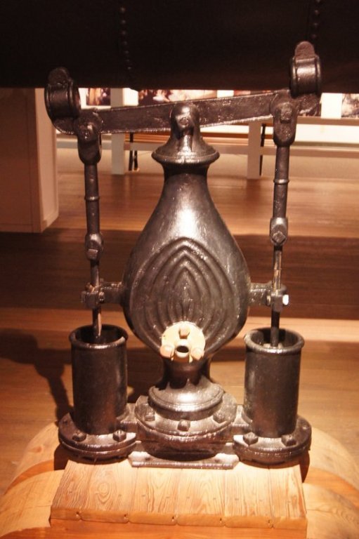
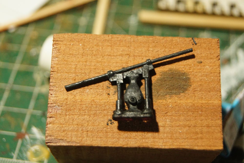
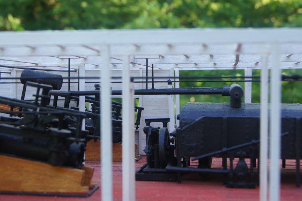
Keith, here's another source of inspiration for a steamboat hand pump. This simple pump was used on Arabia to prime her doctor engine, and as a general-purpose pump for other low-pressure needs. It sat right next to the main boiler. This is from an earlier era (1856) but might still be of interest. Here's the original (my photo from the museum in Kansas City): And here's how I recreated it at 1:64: And in position on the model:

- 732 replies
-
- 10
-
-
-
- Lula
- sternwheeler
- (and 1 more)
-
Lynn, so great to see you back, we'd all worried when you went silent. I've used both needle threaders and the glue method to good effect. A bit of practice and I bet you'll get the hang of either. As another Missouri resident, we're going to get slammed this weekend, so good luck staying warm and safe.
-
Wait until you seen the Lego Titanic: over 9000 pieces and 54" (135 cm) long. Given the massive demand for this Endurance kit, I'd love it if Lego decided to keep doing heritage ships. I'm up to bag 12 on my Endurance and it's an absolutely wonderful project.
-
The term "rubbing rail" comes to mind...not sure if it was used for steamboats specifically but it certainly refers to an extra wale-like strake that provides protection around a hull. Like Jim, I'm astonished and dismayed that it took me this long to discover your new build. Apologies! You do great and fascinating work and I'm so excited to finally be following along.
-
Those are the studding-sail (generally shortened and pronounced as "stun'sl") booms (or yards), they're used to extend the regular yards to pack on more sail when desired. They support the, you guessed it, stun'sls, small extra sails set outboard of the regular ones. Only used under certain conditions. My personal feeling is you'll find it easier to do a consistent job of lashing the sails to the yards if you do it on the workbench, but whatever feels right to you. Try it on the bench, and if you're not happy, you can always undo the lashing and try again on the model. But if you start on the model and don't like that, it'll be harder to retry another way.
-
Well, don't I feel terrible for forcing you to share this awful news. I'm so sorry to hear that. I'm all too familiar with how tragedies can yank you out of normal life and reset all your priorities. My most fervent best wishes for you and your family as you work together to build a way forward.
-
Really nicely done so far!
-
Hi there, I picked up an Endurance, too, and was considering doing a build log for fun when I thought I'd check and make sure no one else had already started, since it probably doesn't need duplication (nice to provide a record of the build, but not much room for customization). So maybe I won't do my own log but just follow yours. It's definitely a gorgeous kit. I'm extremely jealous that you got a lifeboat, as online they were gone by dawn the first day (sales started at midnight) and judging by online reactions there are a LOT of angry people out there who felt cheated that Lego didn't make nearly enough lifeboats to go along with the Endurance and are claiming they have no plans to make more. If I had known that (the marketing said they were available for a three-day peroid) I might have set an overnight alarm. So please enjoy that little kit for me and all the others who weren't so lucky. Have fun in the build! EDIT: I meant to thank you for posting about this in the first place, as that's how I found out about it. Polar exploration history is definitely a niche interest for me and I've read quite a bit on the subject. My wife has even seen the real James Caird in person, and we have a friend who is deeply involved in the US Antarctic research program (they also got a kit). Thanks for bringing it to my attention in time to order one for Christmas!
-
Brian, when do we get to unwrap new photos of Caroline? Hope all is well for you, it's been a while.
-
That last photo is an early Christmas present. What a great set this is going to be!
- 732 replies
-
- 4
-
-
-
- Lula
- sternwheeler
- (and 1 more)
-
WOW. You're braver than I. Please remind me, how did you settle on that design?
- 732 replies
-
- 4
-
-
-
- Lula
- sternwheeler
- (and 1 more)
-
As a fellow scientist (geologist and naturalist) the Beagle is on my life list as well. I'll enjoy following along. Back in 2018 I was able to visit a life-size replica being built in Chilean Patagonia; I posted some photos here (see comment #14) as part of a longer thread on Chilean maritime history.
-
I'm glad you cased the model; much better for it and your viewers!
- 132 replies
-
- 2
-
-
- King of the Mississippi
- Artesania Latina
- (and 1 more)
-
Oops, I didn't look at the different username when replying. I'm on a roll in this thread. Another way to get a varied effect is to lightly stain several batches of gravel with subtly different tones, then mix them together. Looking forward to seeing what you come up with!
-
Yes, I agree, that looks like a nice match for the reference photos you provided, assuming you're comfortable with the scale (I can't quite judge from here).
-
With those additional photos I agree and stand corrected; much of that does look platier. I'm not directly familiar with the geology there so the bedrock may be dominated by something like slate that would produce the platier texture. I shouldn't have been quite so definitive based on one photo and apologize for getting ahead of myself. I wonder if some cat litter would be an option; some versions can have a platy texture that might look really good if the grain size is right.
-
This is a very creative idea! As a geologist with an eye for accuracy, I'll note that gravel landscapes like this should have no sharp edges. Everything is thoroughly rounded by glacial action and overall extreme weathering. If the work shown above is just the sub-landscape you're planning to cover with fine gravel, great; it'll convey some of the underlying terrain's unevenness. But I'd argue that none of the straight-line effects should show clearly through. What you have right now looks rather like a highly weathered granite face full of fractures, but there's no solid rock shown in your reference image. Also, depending on how much you care about accuracy, beware of using products like model railroad ballast for your actual gravel. Most ballast products are angular, because that's how ballast is made (crushed stone), but natural gravel is entirely rounded. Depending on your scale, natural sand (from a creek, beach, or even gardening center or hardware store) would have a much more accurate appearance. But you may or may not be able to source sand in the right grain size...
-
LOL, that's fantastic! And here I was, looking forward to seeing how you built those itty bitty paddlewheel frames...
- 732 replies
-
- 5
-
-
-
- Lula
- sternwheeler
- (and 1 more)
-
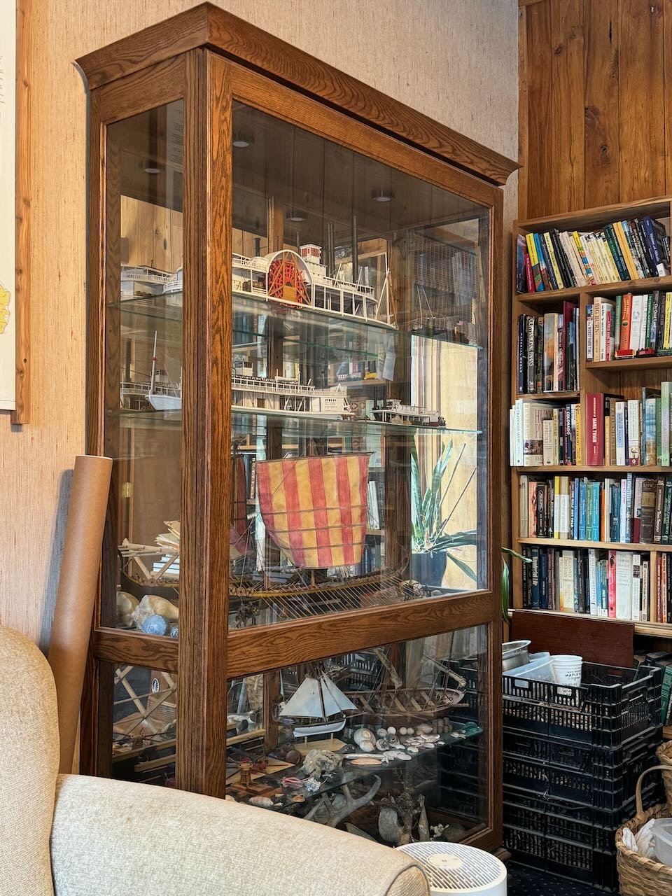
Kurt, fair point. To me, and I suspect many modelers, the point at which I sell or dispose of my models is when I can no longer appreciate them. So at that point it's up to the buyer/receiver to decide what's best for them. Maybe the new owner wants a different style of case, or has a pre-existing display setting (like their own curio cabinet). For example, I've had some interest from a local historical society in some of my steamboat models. They wouldn't want them in individual cases, but would rather display them within a casing context they'd develop to fit their display hall. If that were to pan out, any time and money I had spent on custom cases would be a waste, because the new displayer doesn't want them and the custom case probably doesn't easily fit a different model I might later build (and same goes if I tried to sell the empty case to someone). Whereas the curio cabinet is much more flexible in receiving whatever new item I want to put into it, or in being passed along to someone else down the road. Obviously the best approach varies by builder/owner. I just think it's worth putting the idea of the curio cabinet out there, because so many casing question on this forum assume that the only approach is to build/buy individual cases per model.
-
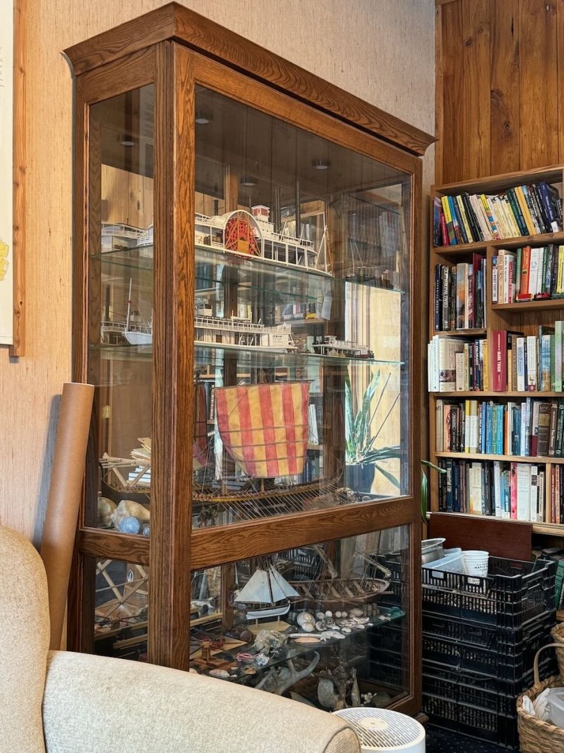
I agree with Kurt, protecting models is important. Once dust and stuff starts accumulating it's surprisingly hard to get rid of it without damaging the model. But I also agree that individual cases get expensive fast and take up lots of room. My solution was to buy what's commonly called a curio cabinet, in my case from a Mennonite builder, in which I can display quite a lot of models in the same horizontal footprint as one or two individual model cases. I have seven ship/boat models in this one case alone, plus three small nautical-themed models, and still have room left over for some neat natural stuff (rocks, bones, shells, etc.). This was obviously more expensive than any one case, but way more cost-efficient than all the cases I'd otherwise need. I've also been able to adjust shelf heights to match different models, again allowing more efficient displays than single models on their own. And it's quite attractive in the home. The other upside to a curio cabinet is that's more flexible in the long run. A bunch of custom cases have little value beyond your specific model, and if/when you need to downsize, they may end up thrown out. A curio cabinet will hold a lot more resale value as they have a much broader appeal. And you can get them in various sizes depending on your needs.
-
That's come together really well. When do you add the 3D printed figure of yourself?
- 110 replies
-
- 3
-
-
- Paddlewheeler
- Ballarat
- (and 3 more)