HOLIDAY DONATION DRIVE - SUPPORT MSW - DO YOUR PART TO KEEP THIS GREAT FORUM GOING! (Only 24 donations so far out of 49,000 members - C'mon guys!)
×

Gaetan Bordeleau
-
Posts
1,307 -
Joined
-
Last visited
Content Type
Profiles
Forums
Gallery
Events
Everything posted by Gaetan Bordeleau
-
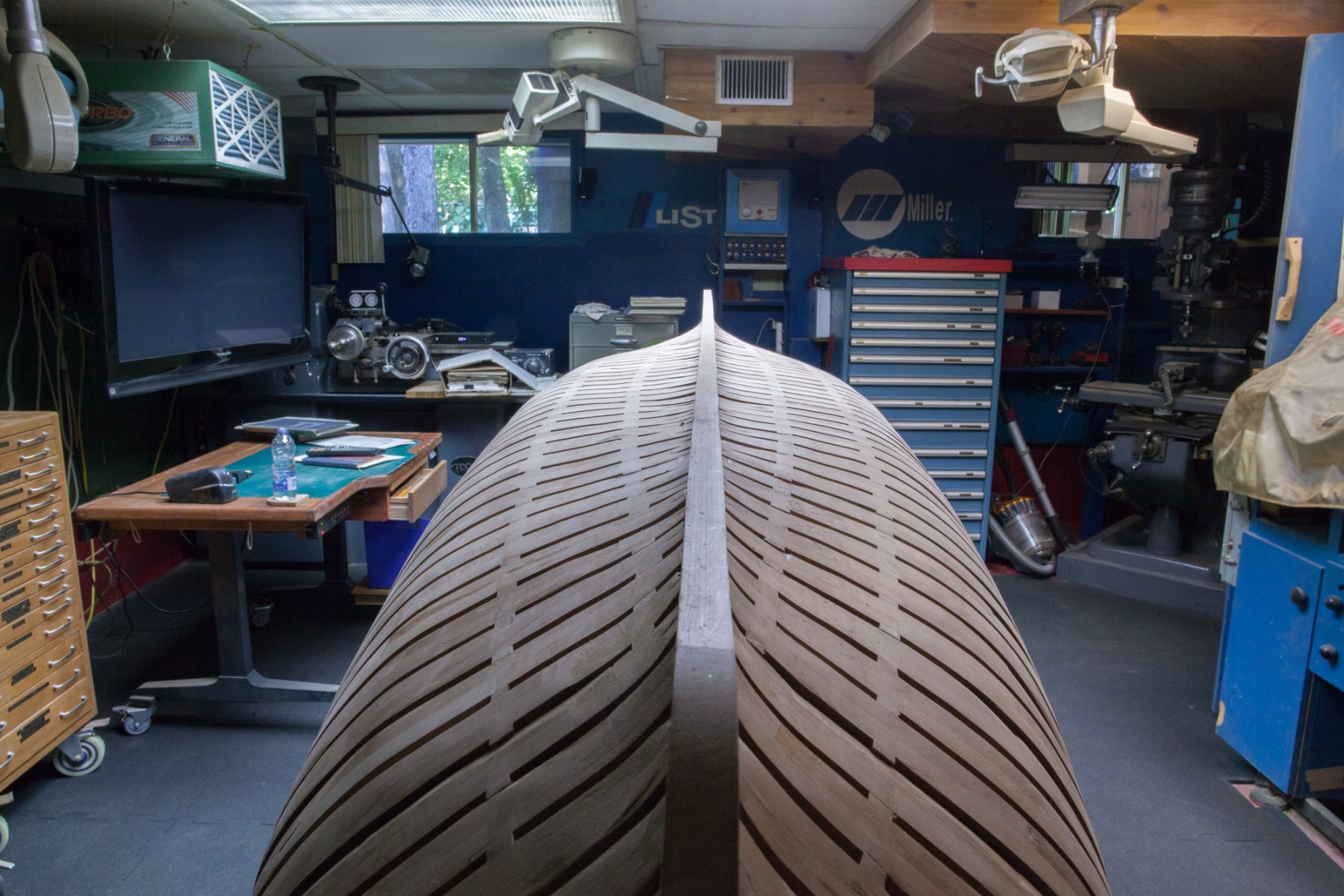
 Here is some dumb thinking. I was talking with a gentleman this morning and he explained to me what is : Stabilized wood. In the Knife making business when they want a perfectly stable wood, they use acrylic resin as a wood stabilizer. The penetration is made by vacuum. Could it work if I could put the model ship under vacuum? Dry parts are almost done and all parts can easily be assemble or disassemble at this stage.
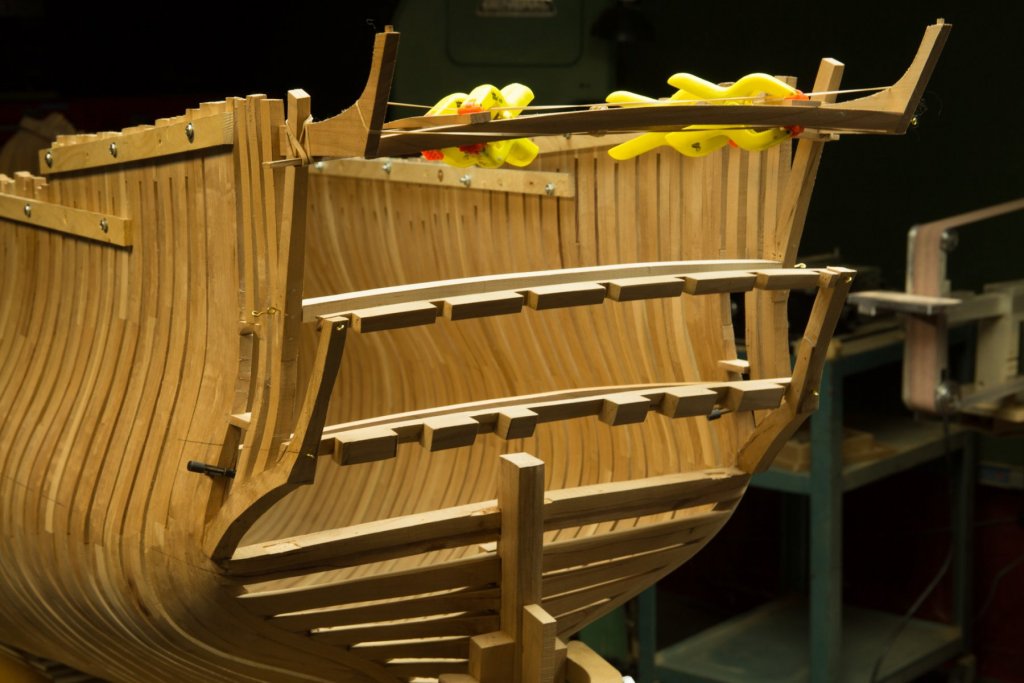
-
Hi Mark, did you try some of the planking especially in the fore bent section? Are the drawings precise enough to include the curved areas?
-
Welcome back to the shipyard Gary, The only way to have the perfect model ship workbench which suit your needs, is to build it, as you done yourself, very nice.
-
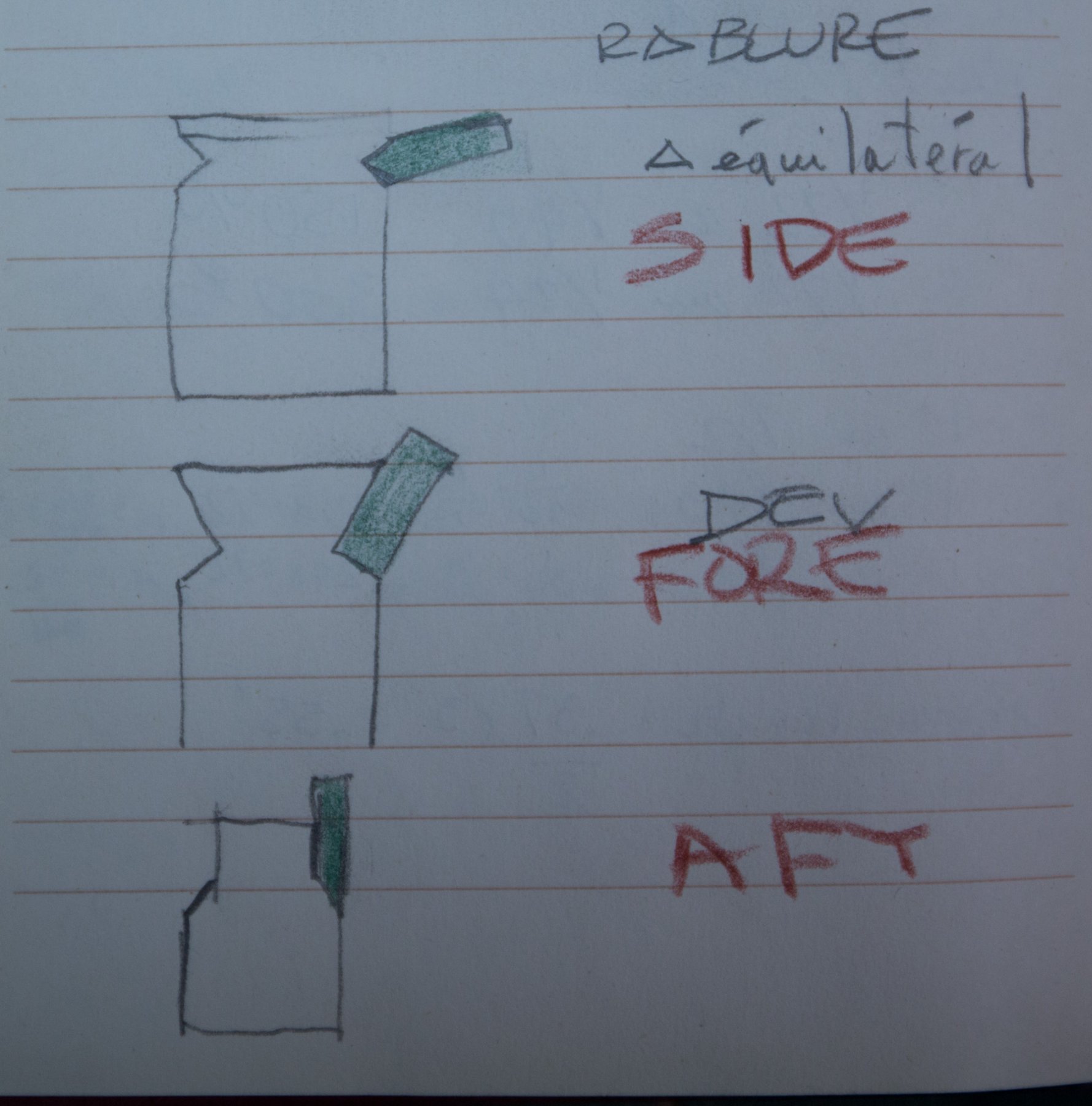
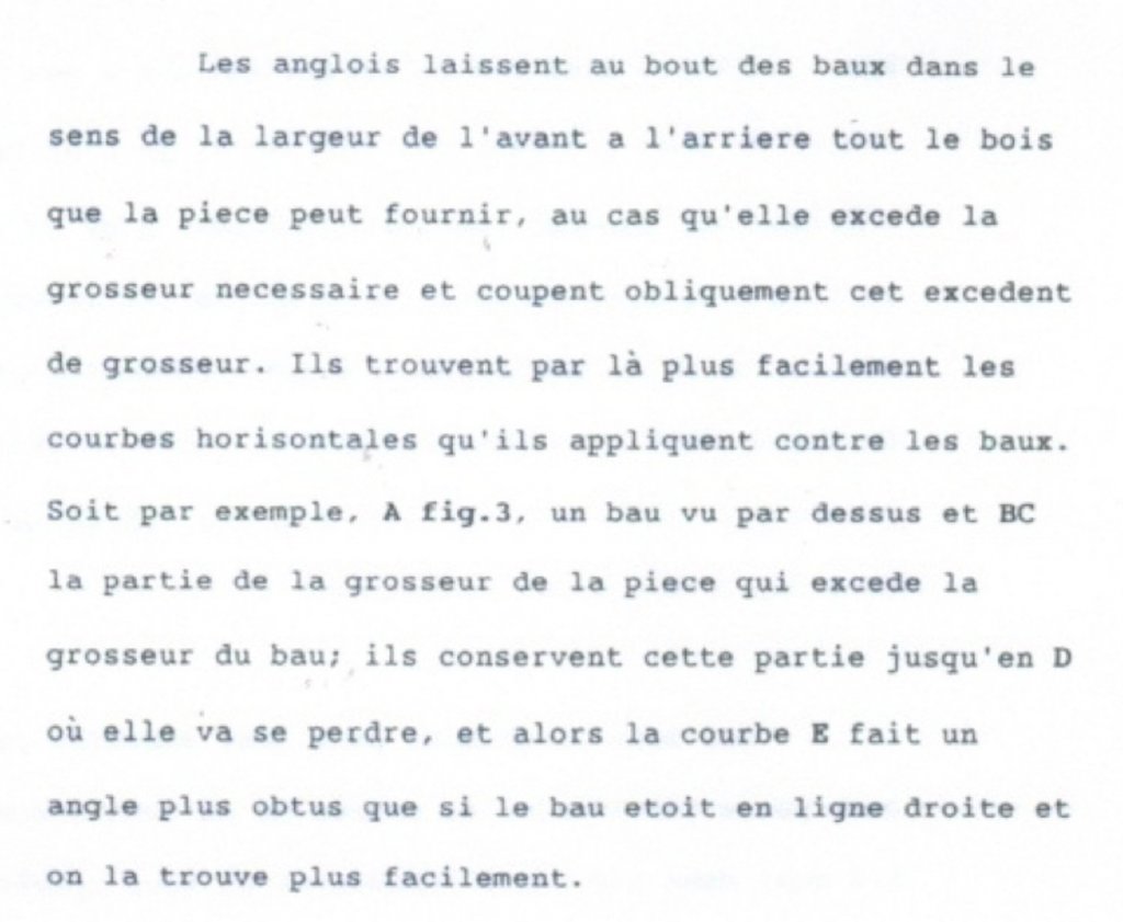
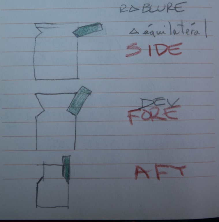
Could someone explain why they add a bevel?
-
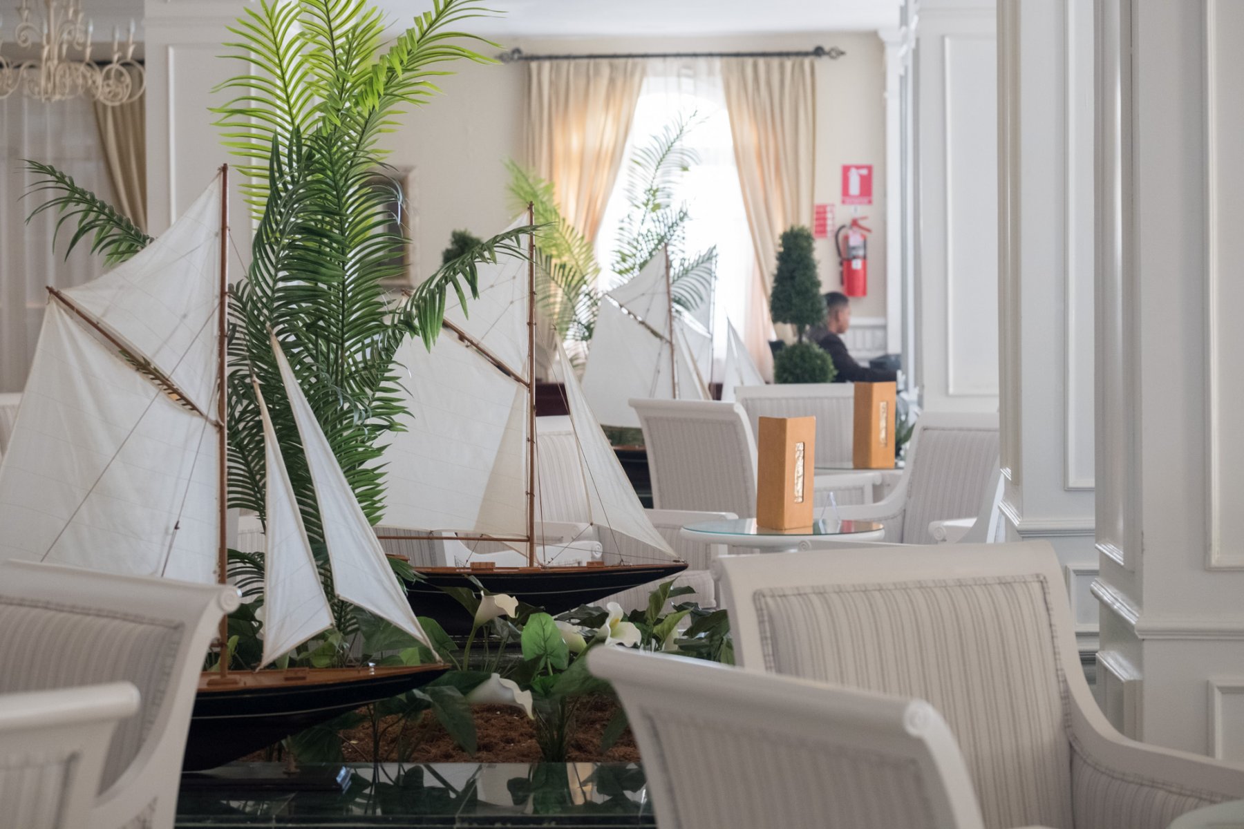
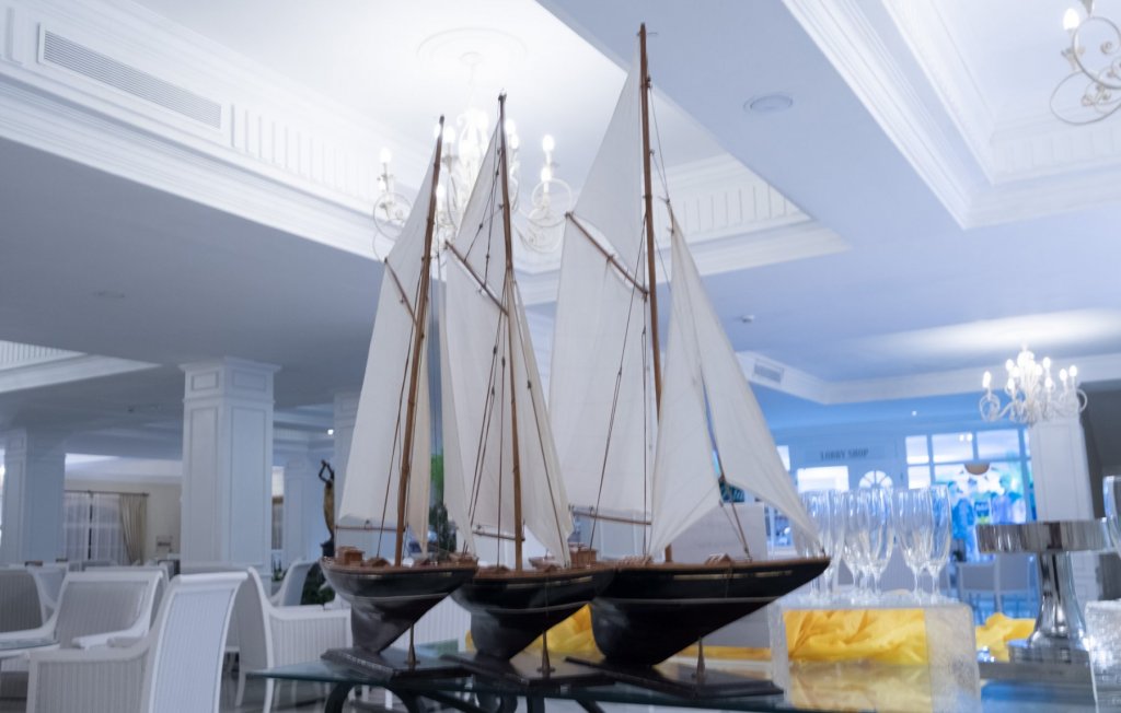
Hi Michael, I do not know anything about the schooners, these were part of the decoration in the hotel. I had enough to always clean the T slots, this way it is very easy to clean and yes it creates 1 more table of work. Basically, there are 2 ways to get a black background : a black fabric, the easy way, or a bit harder with a flash close to the subject. Hi Druxey, building a model ship is very interesting, fine tuning tools is also very interesting, it takes time but at the end it saves time. Hi Mark, reinstalling the knives may looks easy, and it was fast and easy, the last shot I installed the knives. But what you did not see is the hour spent before trying to do the job different ways trying to understand how to do the job. For these kind of jobs, using jigs is easier and more precise. I tried to measure heights with an electronic caliper but it was too much difficult. It is only when I understood the principle that the job became easy.
-
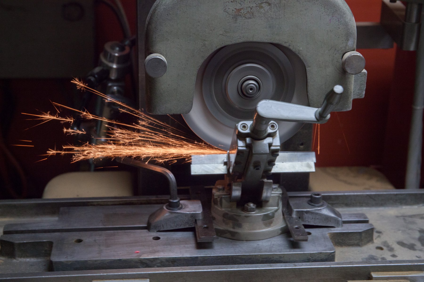
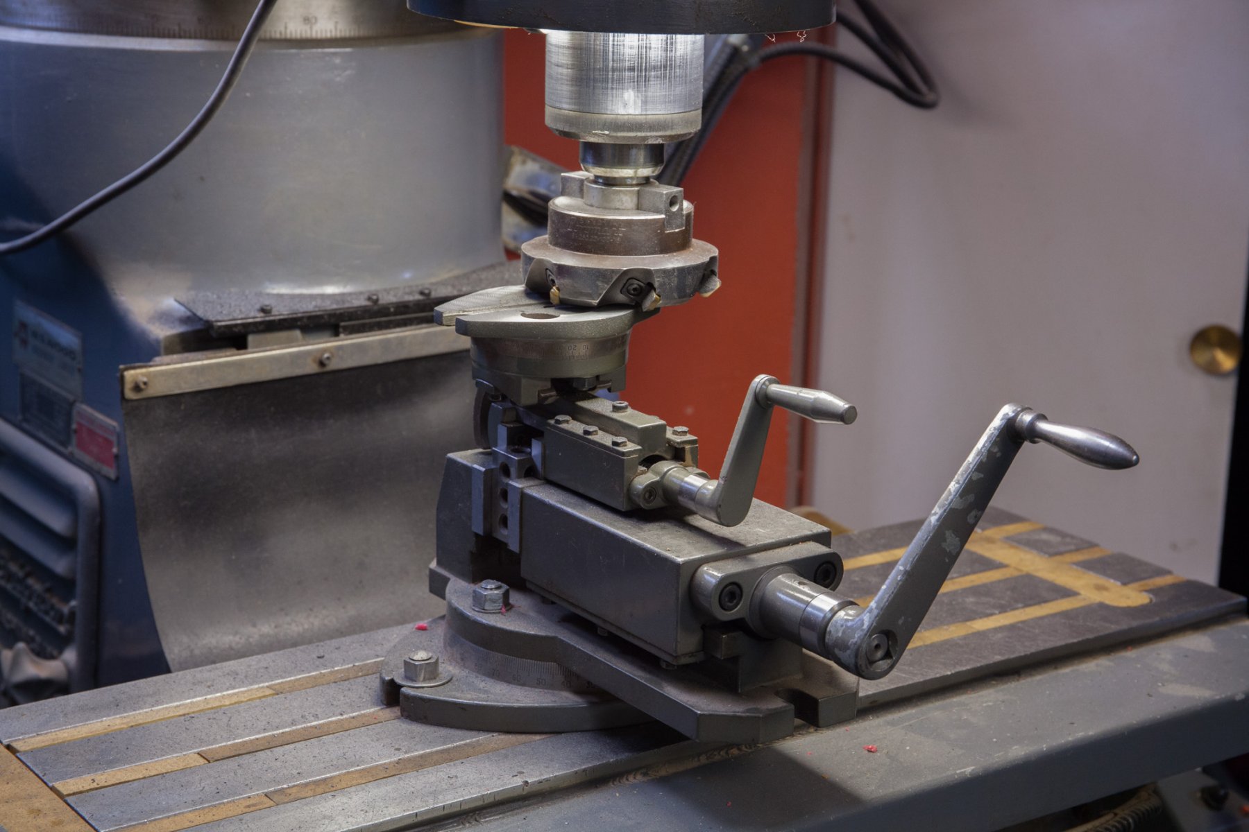
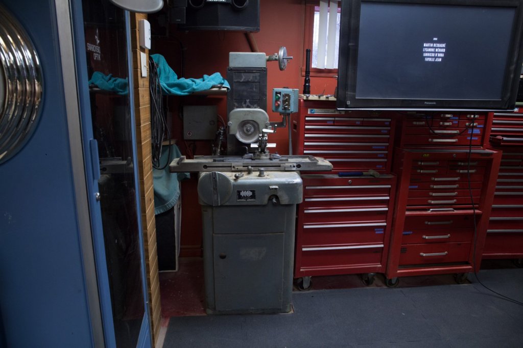
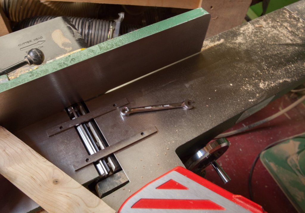
I did not touch the 74 for few weeks. I only had these 4 schooners to play with. Back at home, it was time to fix few tools : Sharpening knives for jointer and planer on the surface grinder. For the jointer, I do not have the tool they give to replace the knives. In fact we do not really need it. Right side of the table is set at 0, left side is set parallel to the other side. Then cutters are height set with 2 parallels as reference... as easy as this. A small vise had the base not exactly parallel to the jaws. Surface milling to fix it. A block is fixed on the big vice. The small vice is set upside down on the big vise. The block is the union between the 2 vises. A surface milling cutter straighten the base.


-
Gluintg metal to wood
Gaetan Bordeleau replied to Jerryi's topic in Metal Work, Soldering and Metal Fittings
Epoxy + pre-drilling holes 1 size smaller than nails so that there is friction. Sometimes nails needs to be inserted with a pair of pliers. When friction is good, glue becomes almost not necessary. -
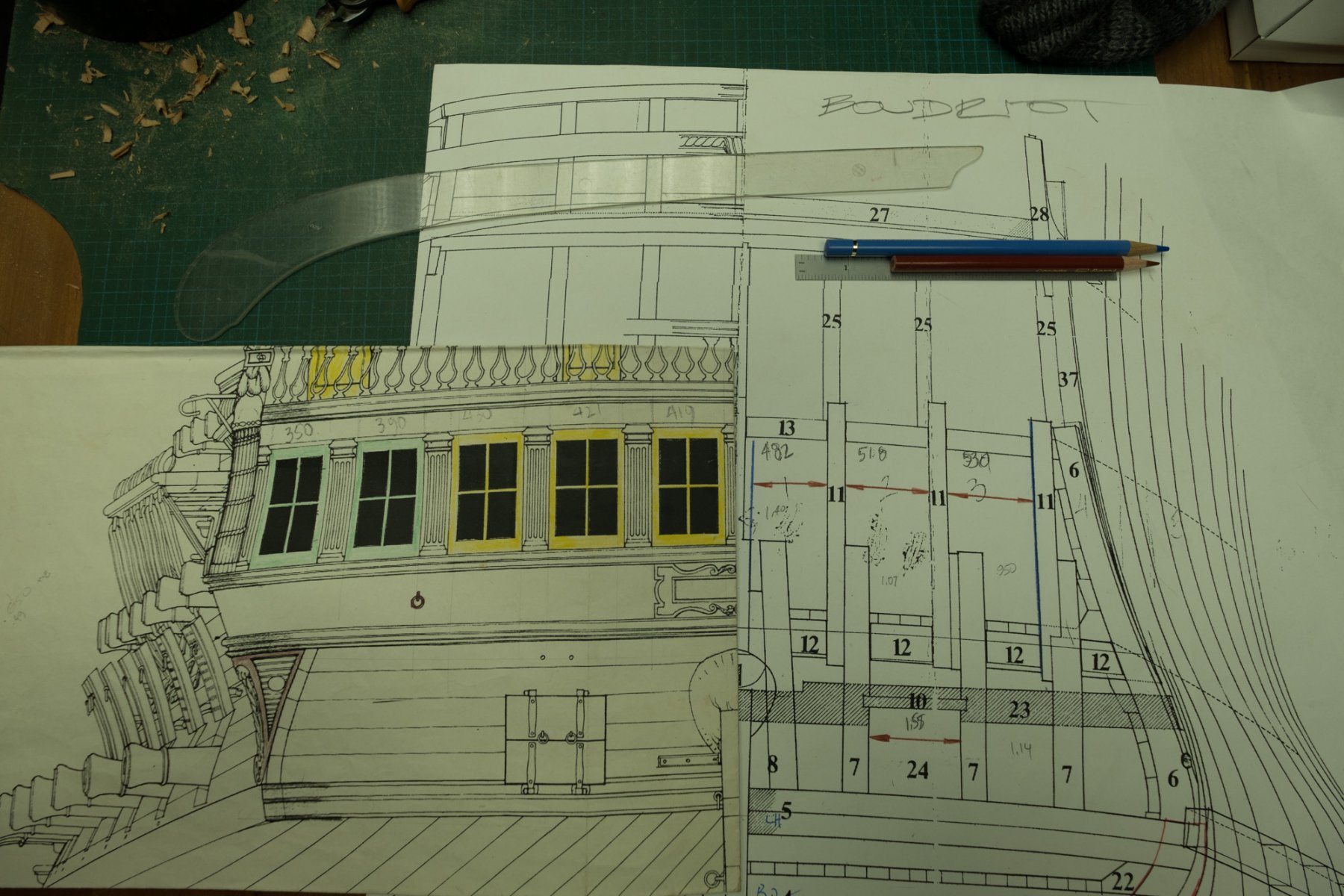
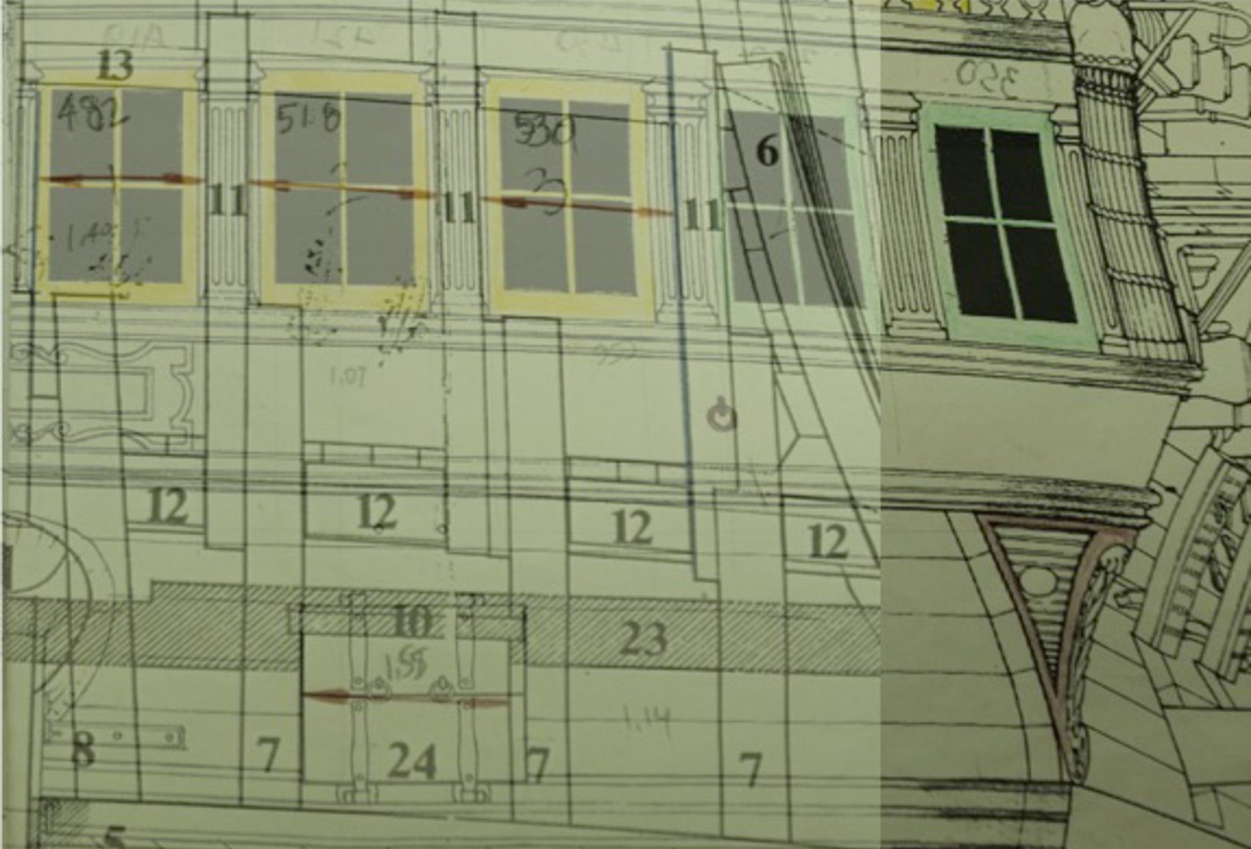
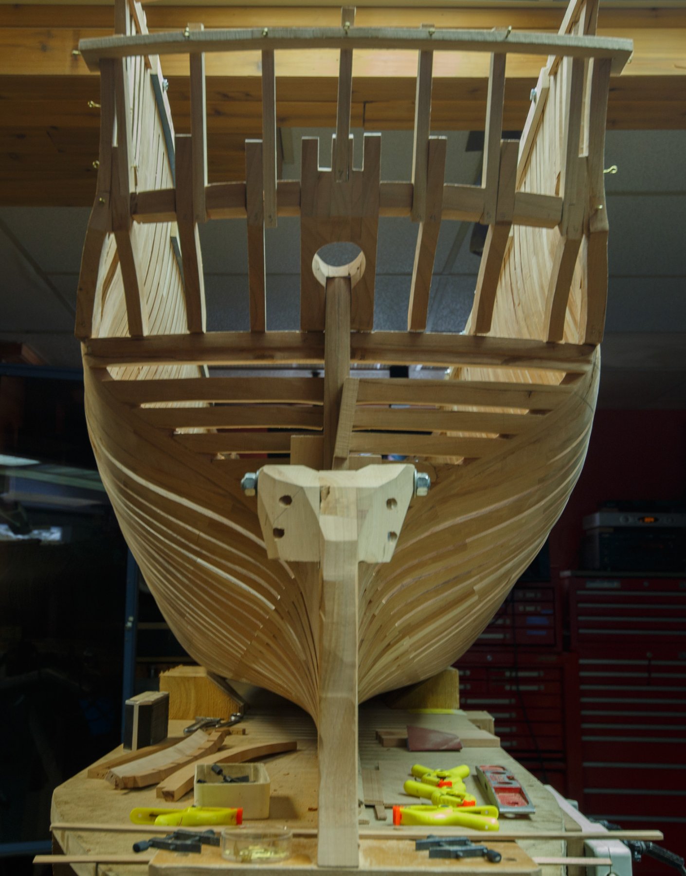
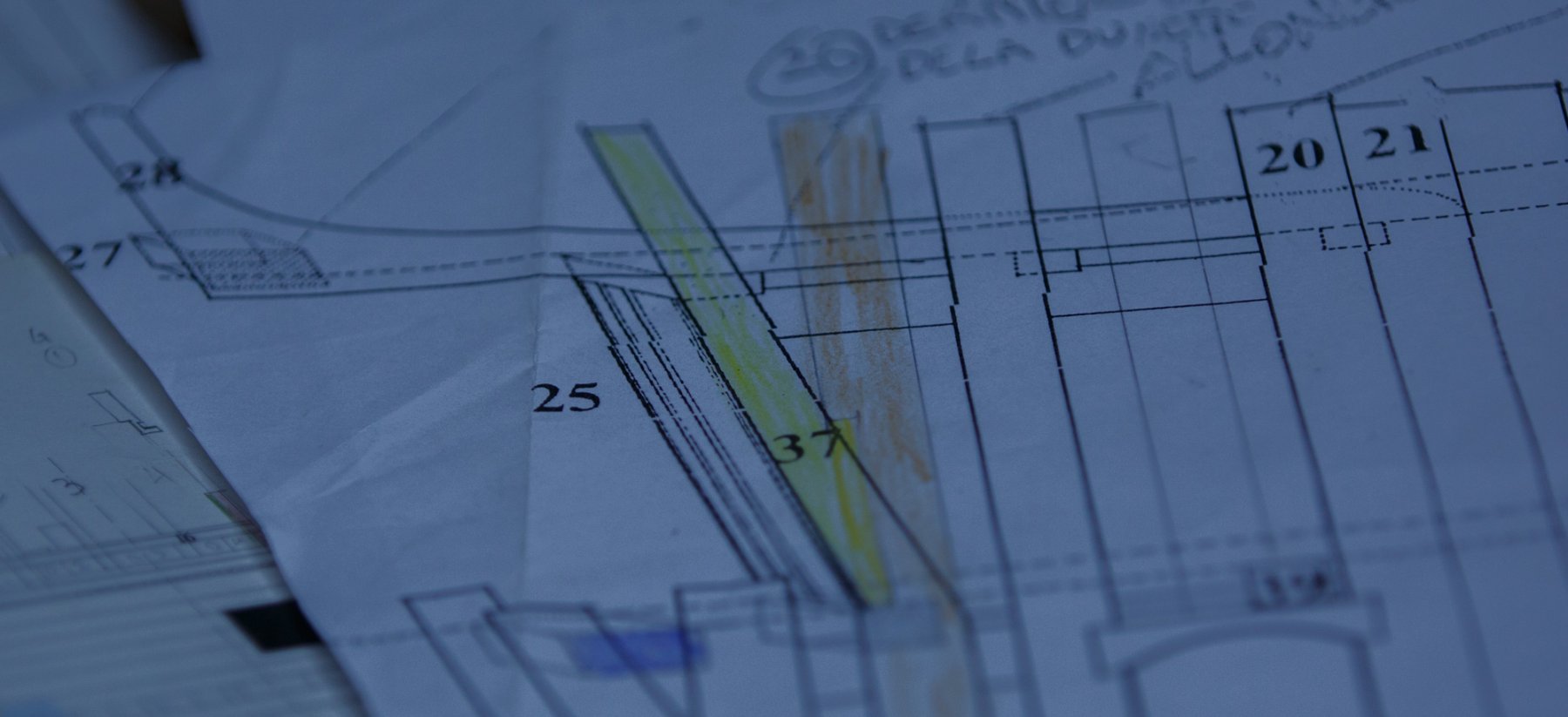
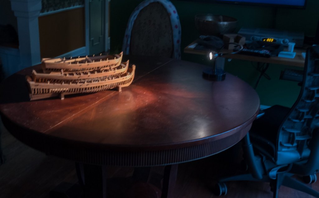
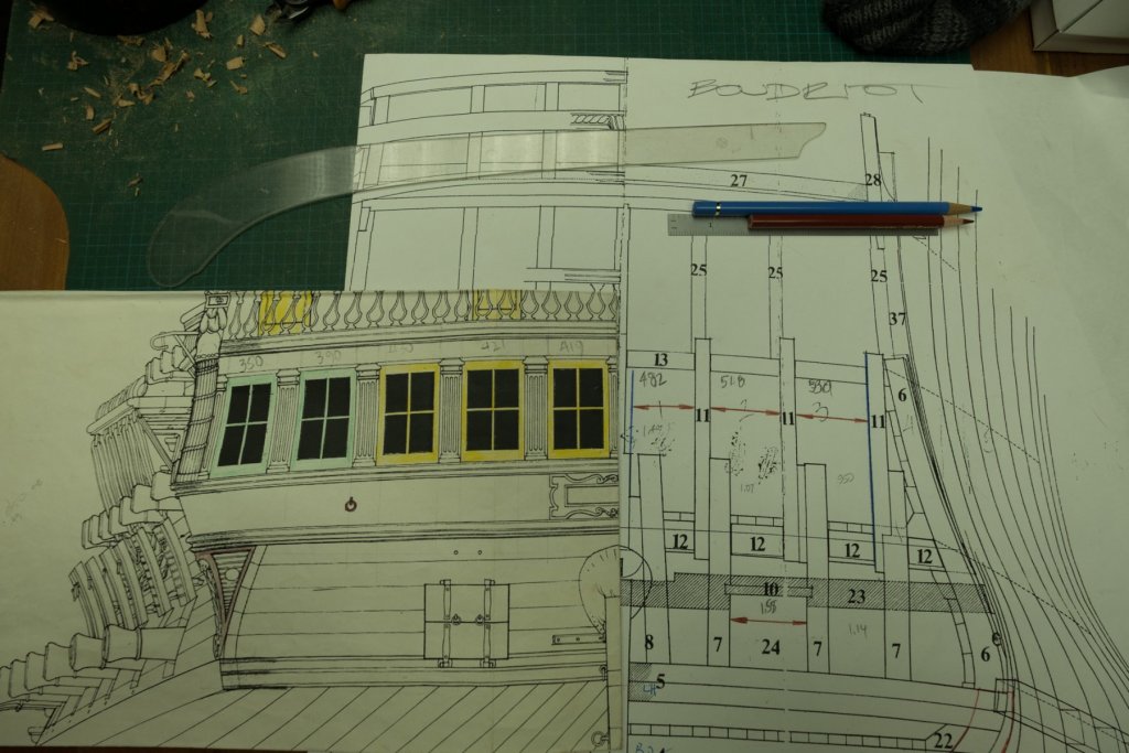
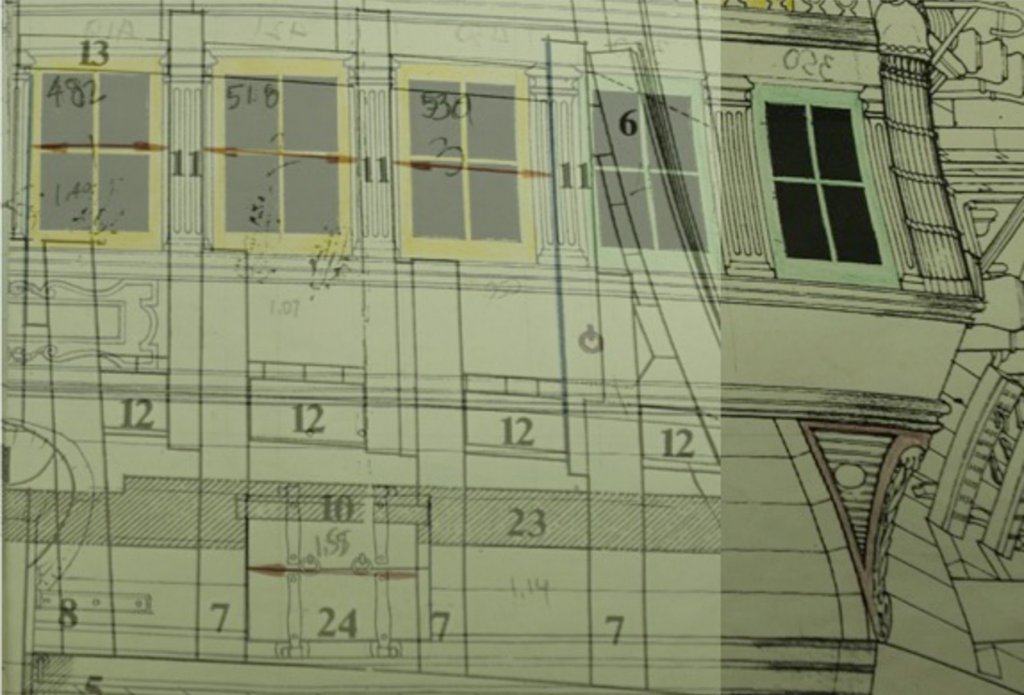
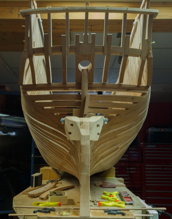
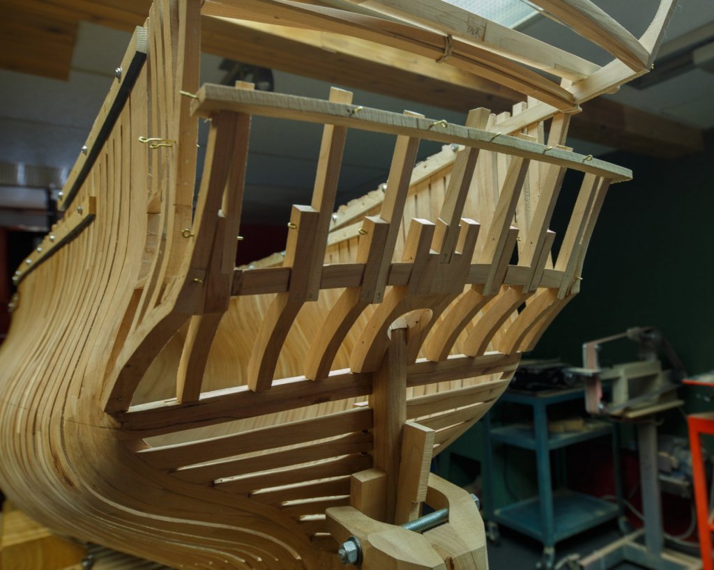
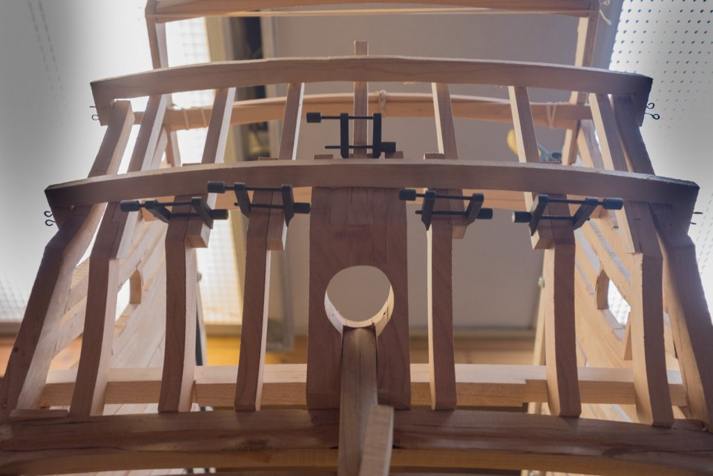
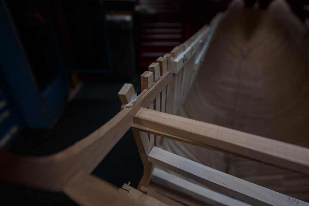
Another photographic test: Taking pictures with an Ikea $20 LED lamp. On the second deck, there will be 10 windows aft. 6 windows are inside the limit of the frames and the other 4 will be added later. Looking at the plan it is difficult to set the width of the windows, so I looked at it a different way to set the position of 8 vertical beams. 3 beams are installed : 1 on each wall and the middle one. Then, each half was divided in 3 spaces between beams. In a global way, these are the only measures needed to set the vertical beams. The width for the gun opening is derived from the setting of 2 upper beams.


-
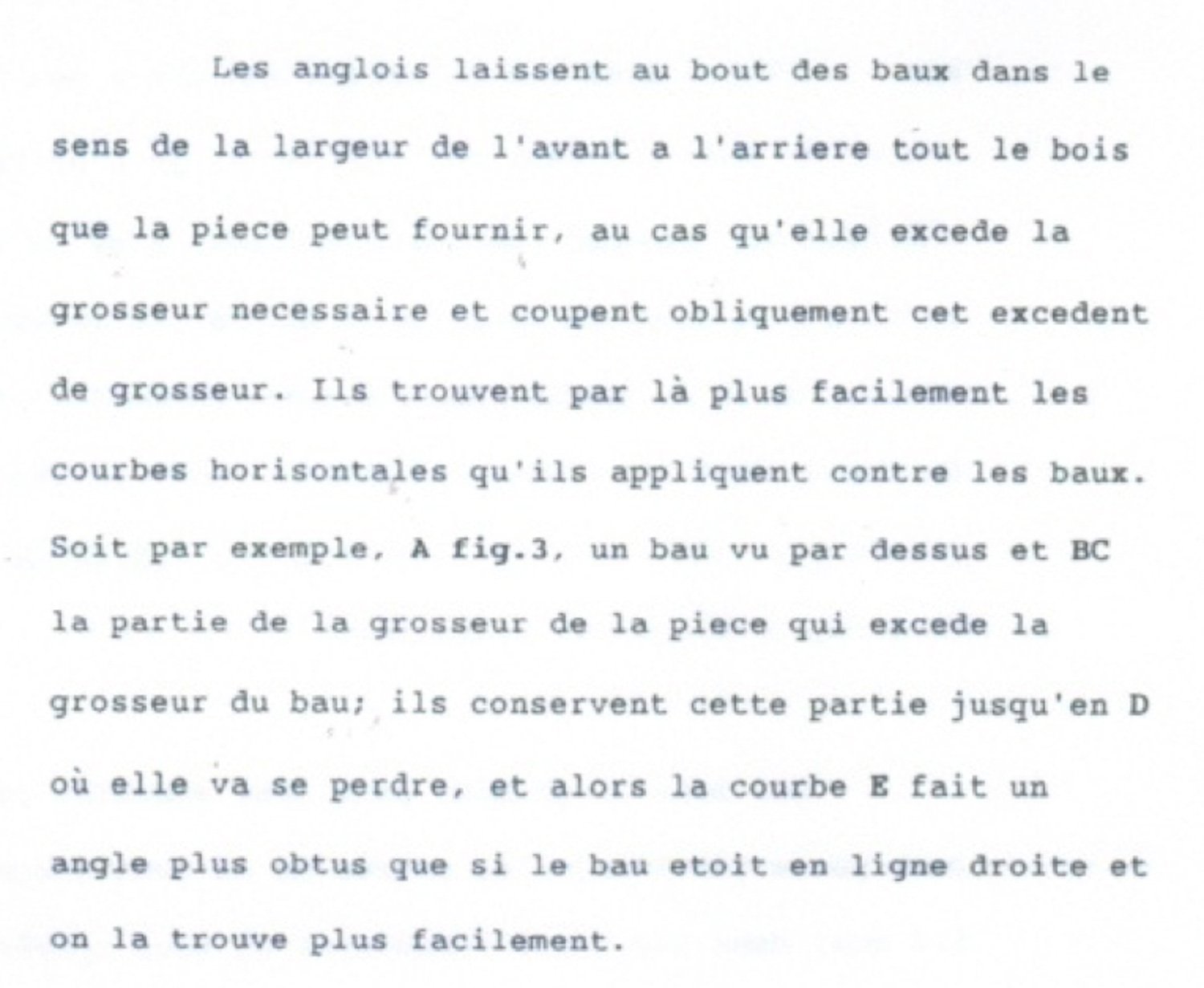
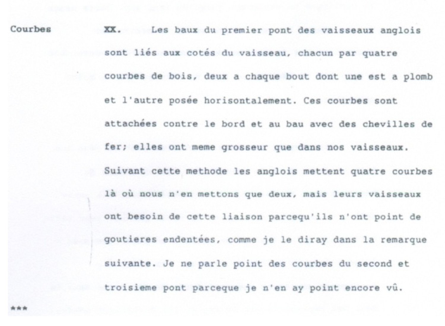
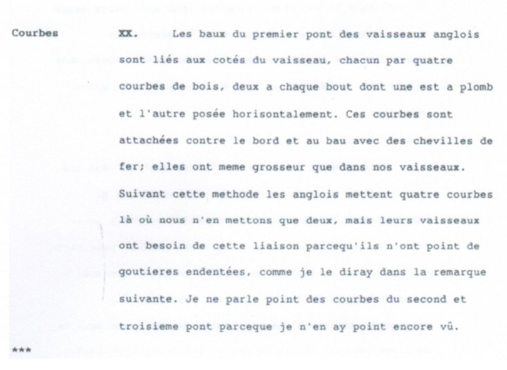
You are not the first one to observe this: Blaise Ollivier: comparatif de la marine anglaise et hollandais avec celle de France. 12 avril 1737 au 29 aout 1737.

-
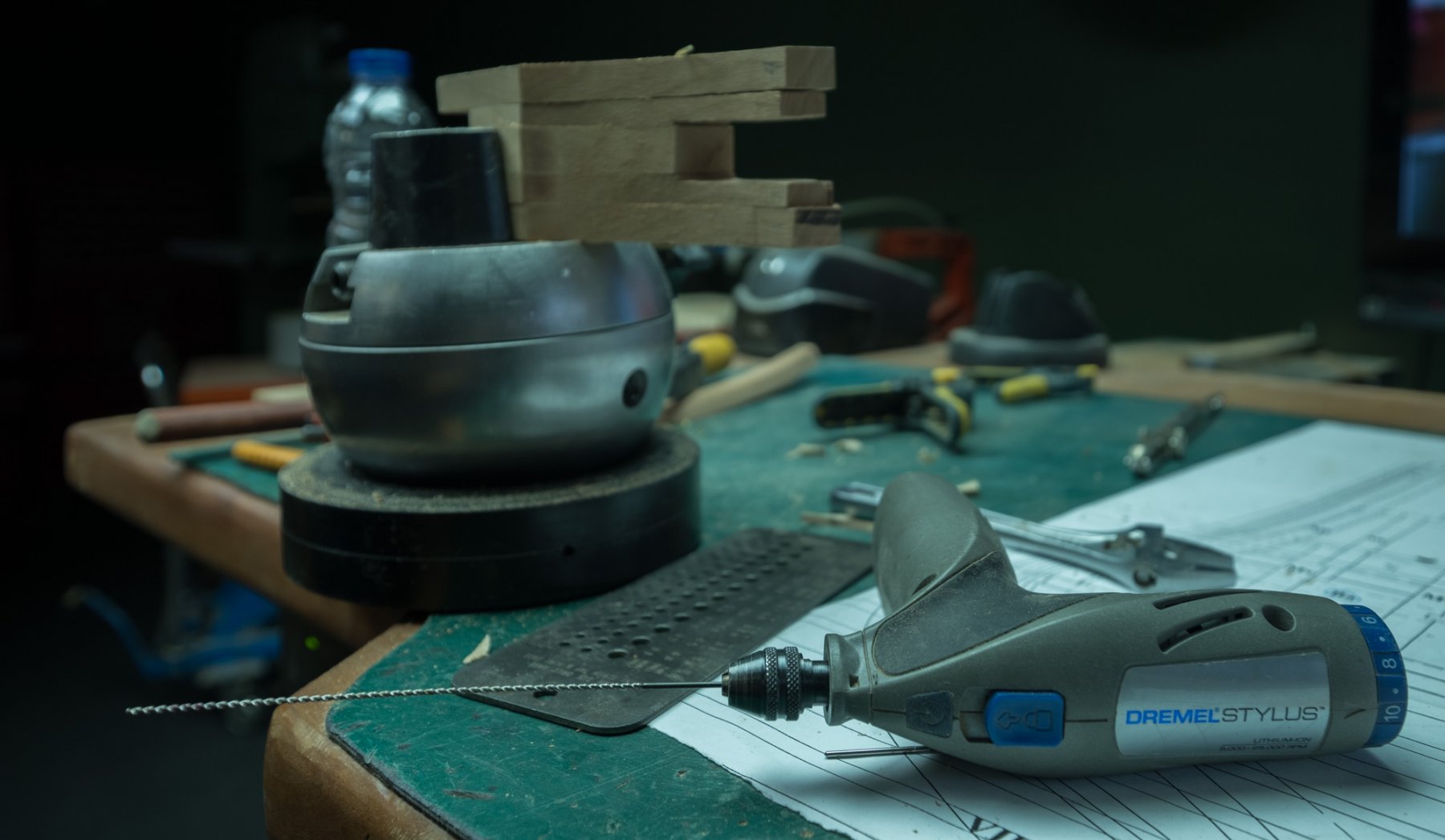
Jet or Dewalt scroll saw
Gaetan Bordeleau replied to Anguirel's topic in Modeling tools and Workshop Equipment
I also use a Hegner, free of vibration... It excels at cutting thick hardwood up to 1 inch in straight line and at exactly 90 degrees. It is also very good at cutting very thin slices of wood few millimeters thick. For jobs thinner than 3/32, it does a similar job as a less expensive saw. -
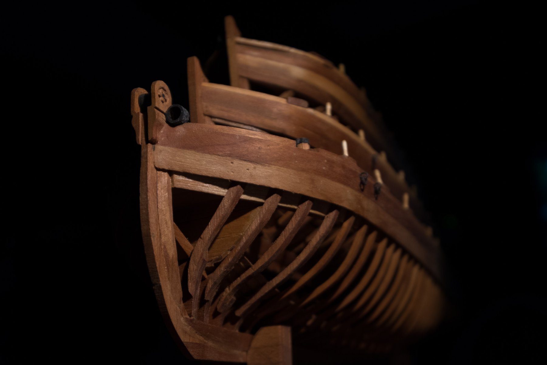
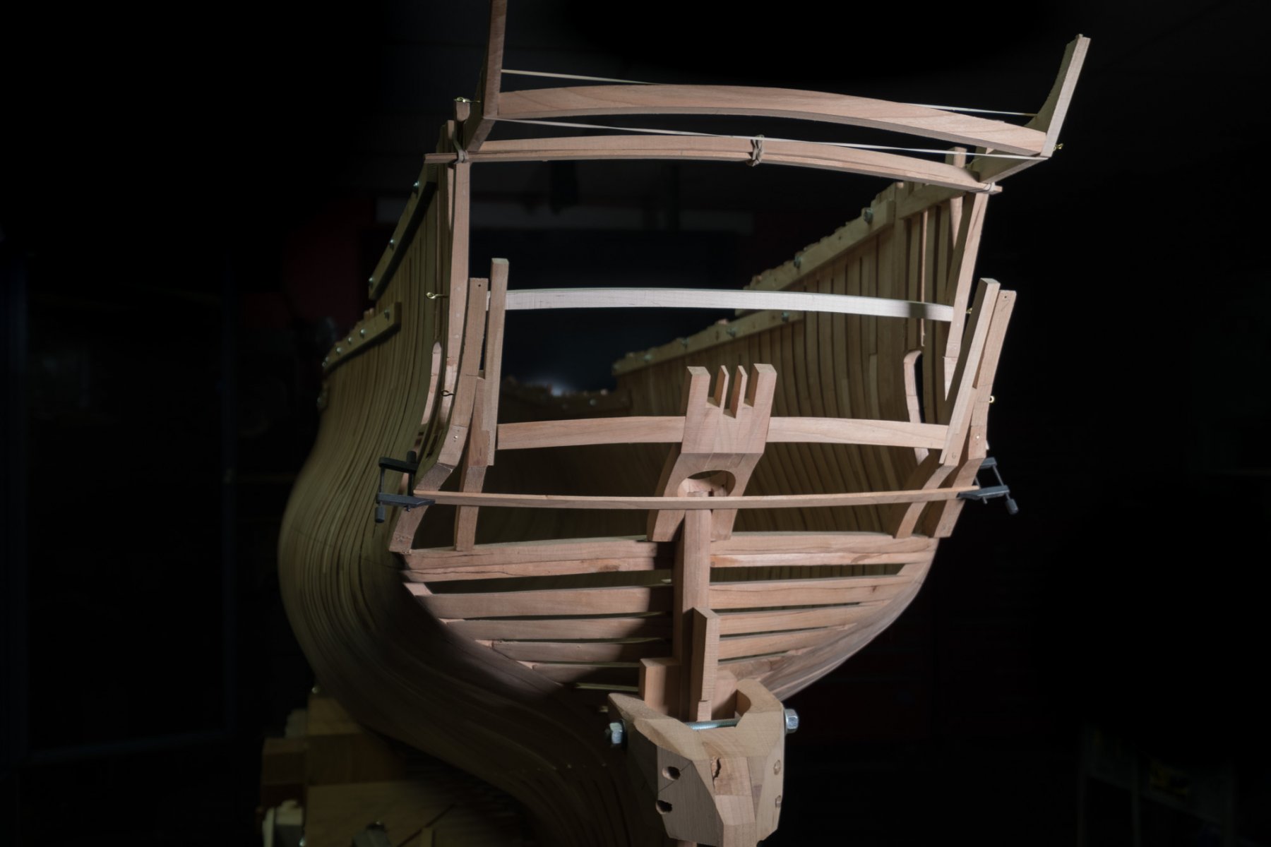
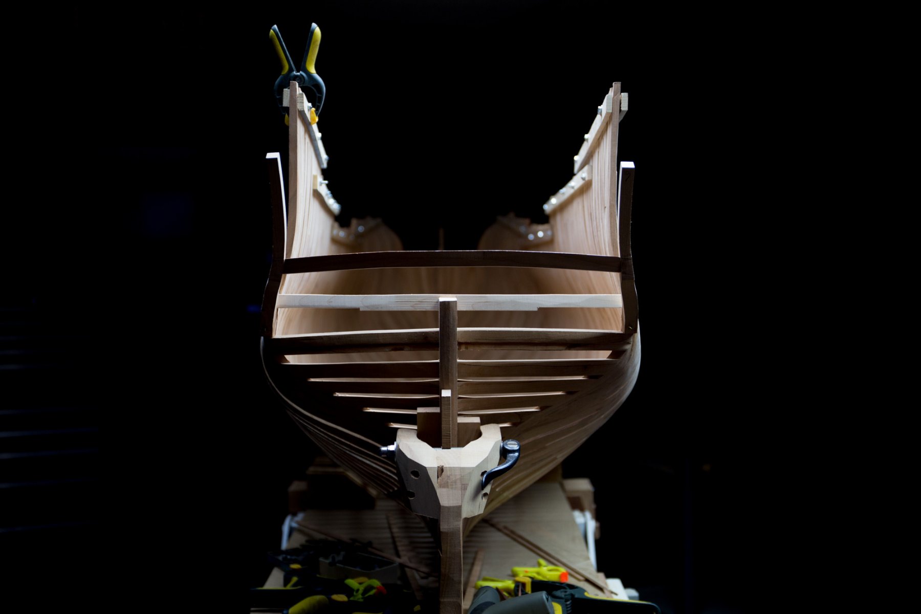
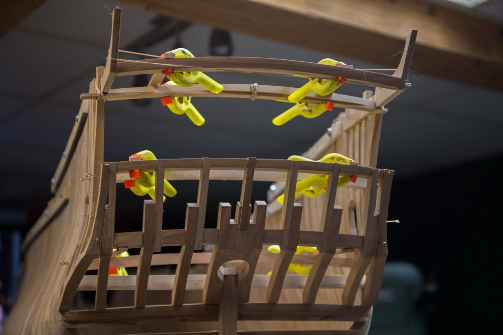
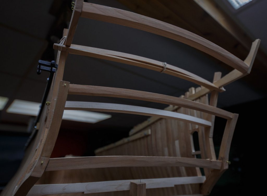
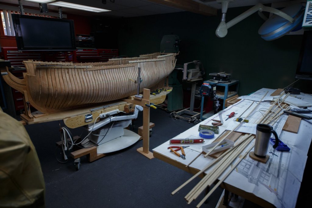
Thank you but in fact it is not a dark background: After supper, no sun, 1 led light and underexposed of -2 F openings Needed to make a hole much deeper than the standard drill bit lenght : So extra long one has been used. Almost everything is fixed temporary. Added 2 horizontal U shape curved beams to hold the vertical beams. The hole for the rudder was did on the milling and then sanded on the oscilating sander. The closer the diameter of the round hole, the better the results. Similar results could not be achieved with a sanding drum a fraction of the hole diameter.


-
Ebony is not harder to work with today's tools, than can be boxwood. Ebony is toxic because the dust is so fine and the finer the dust the deeper it will go in the lungs. Every kind of wood can be toxic but if you wear a mask, you can solve most of the problem and as you say: nothing looks and feels like ebony.
-
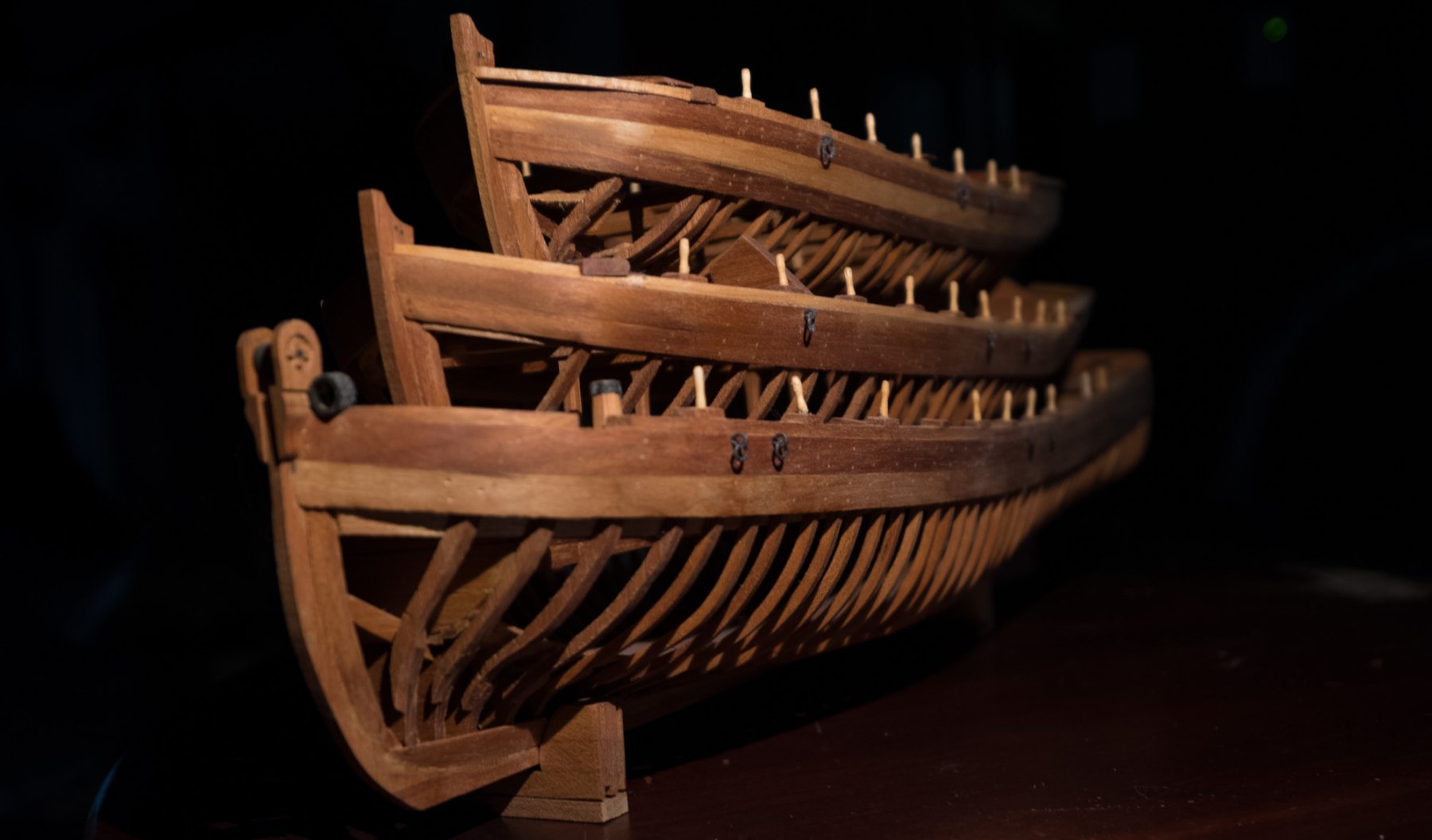
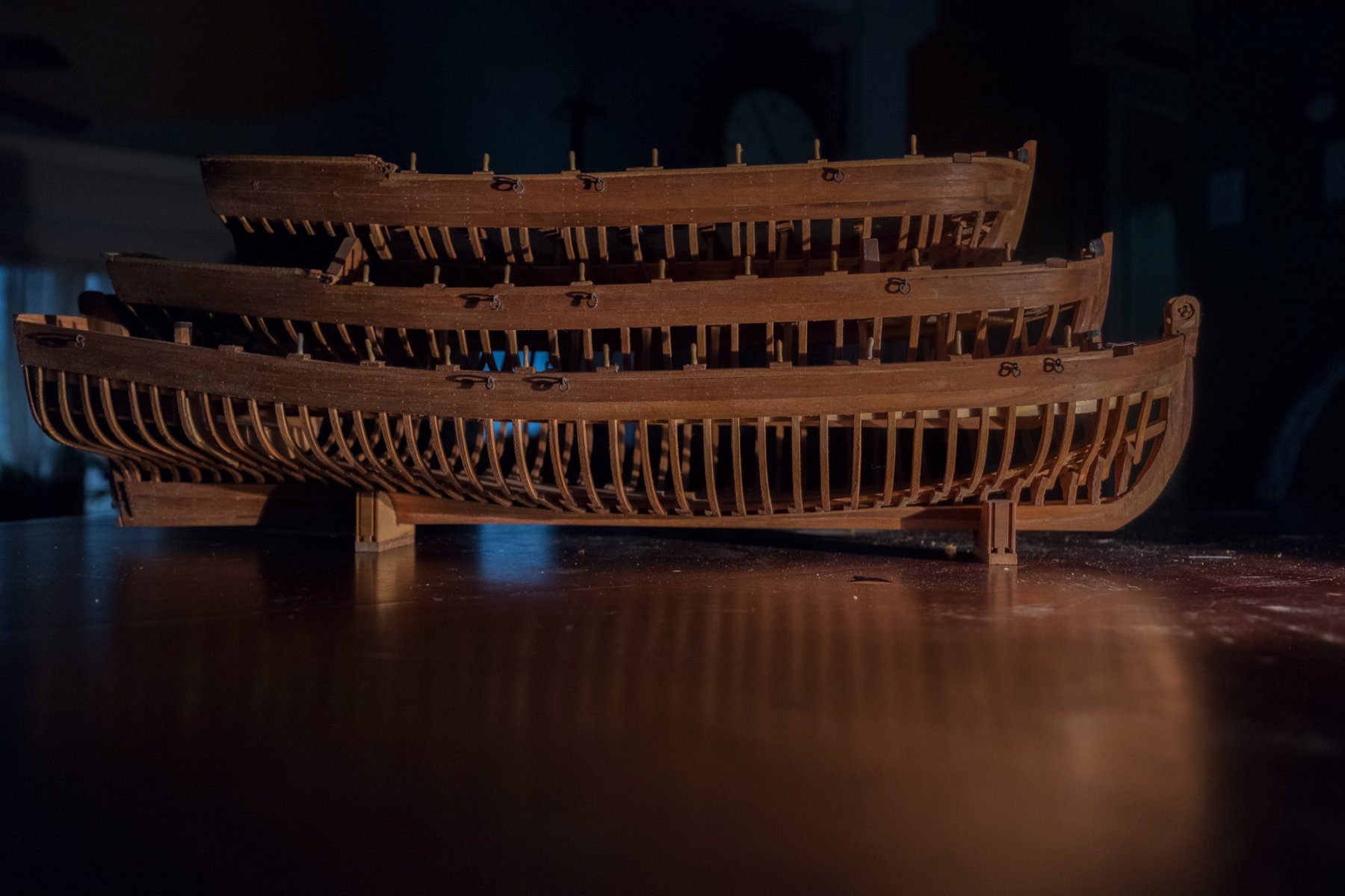
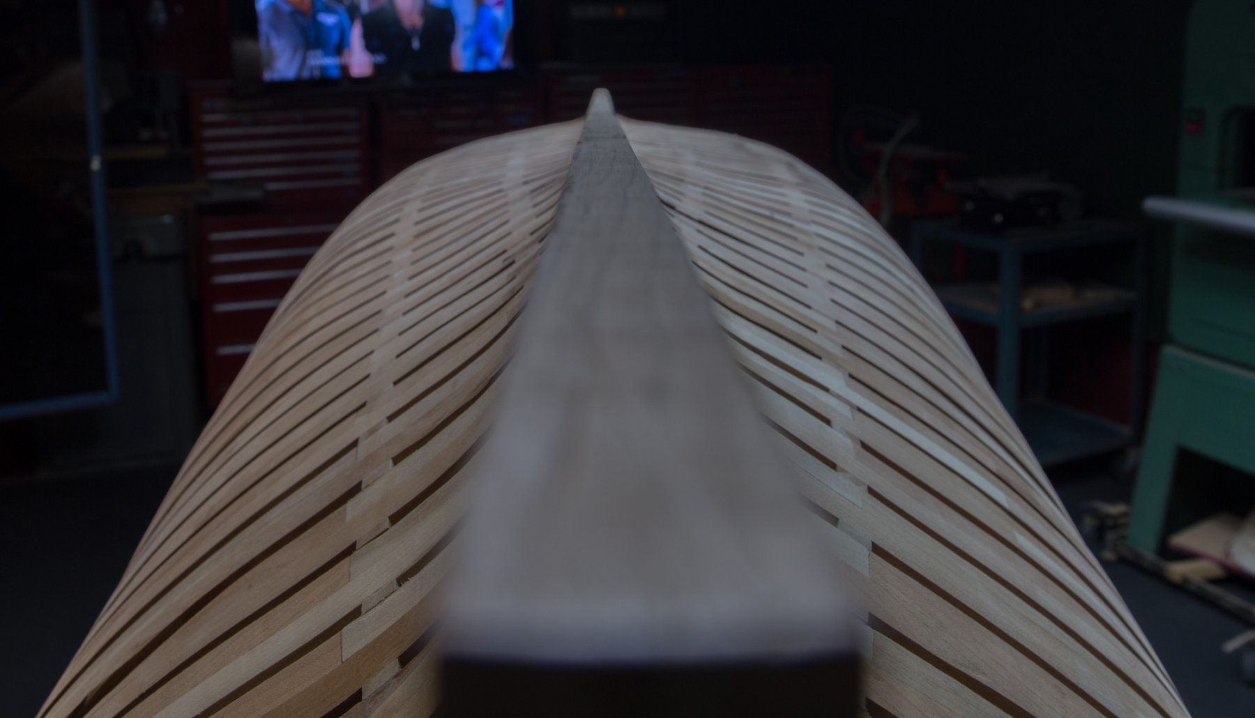
thank you and for those who love dark shots:


-
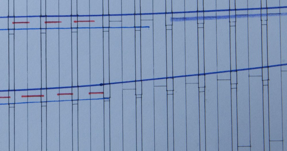
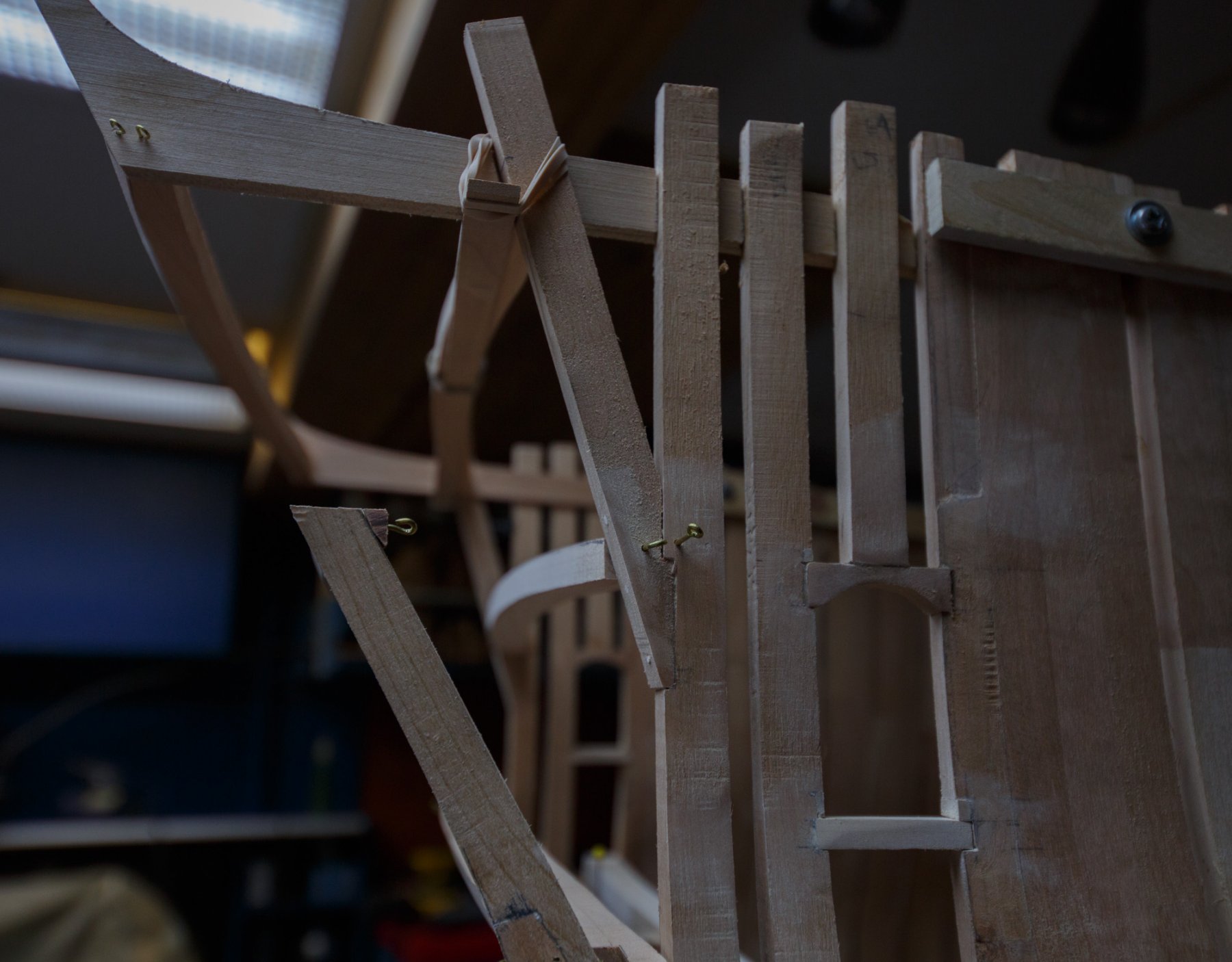
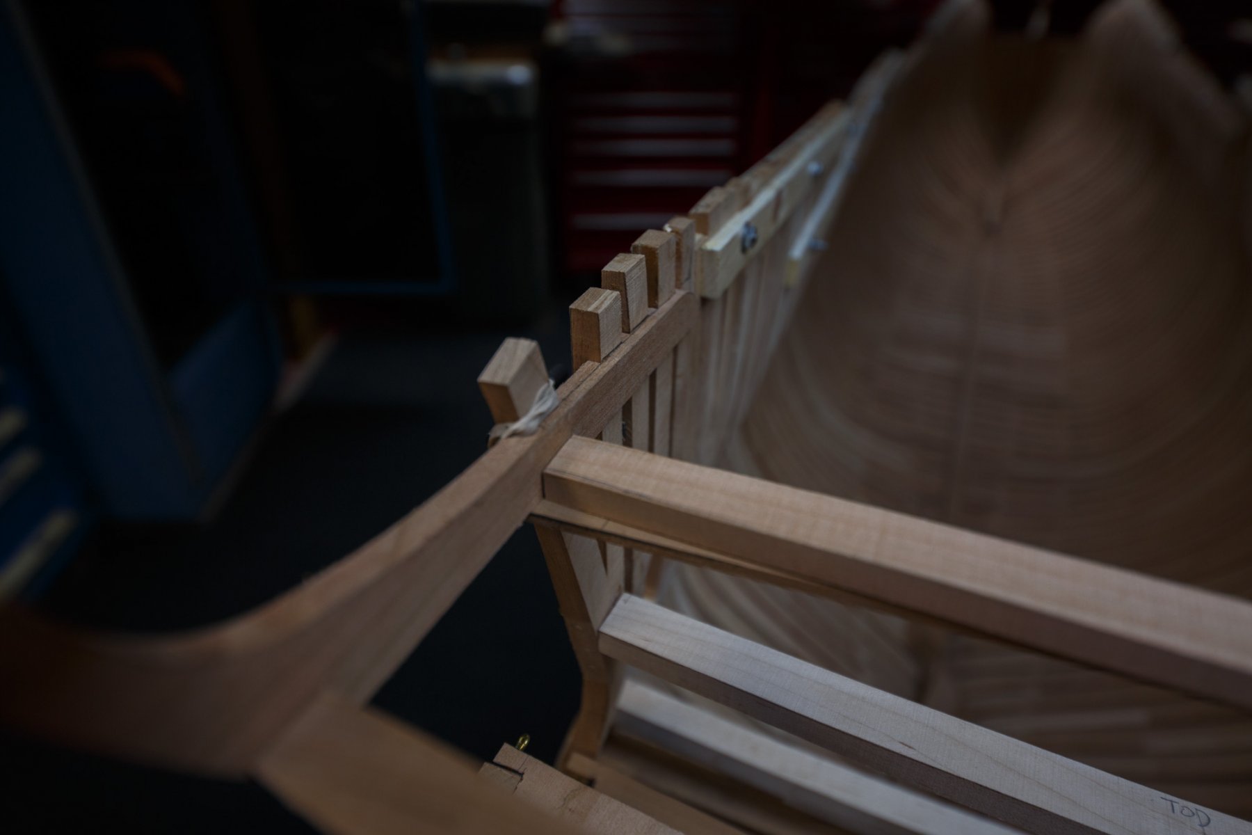
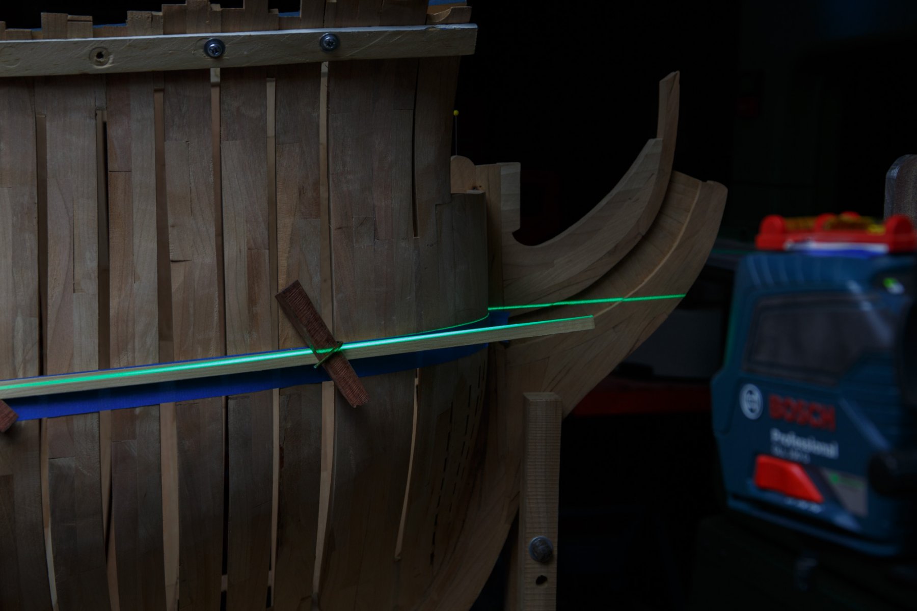
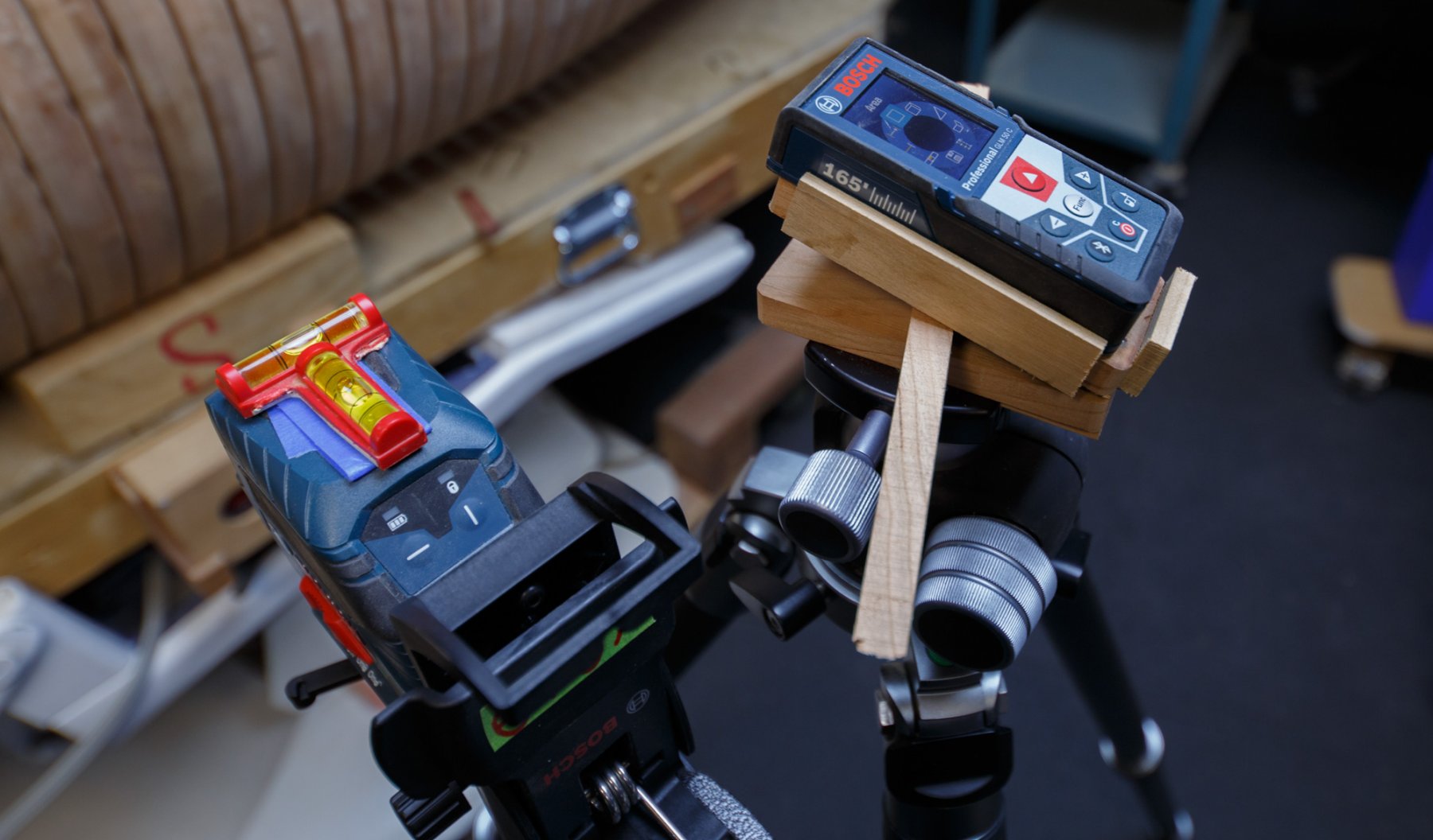
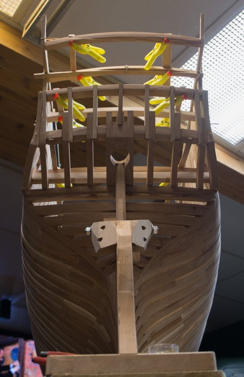
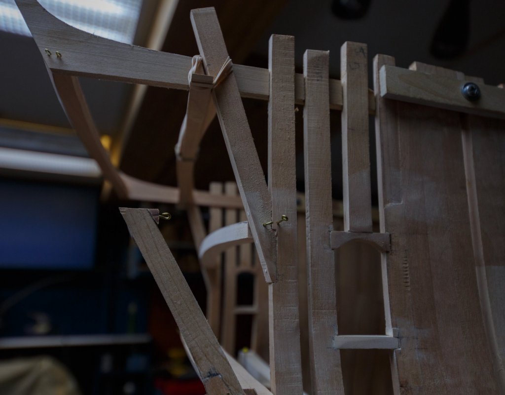
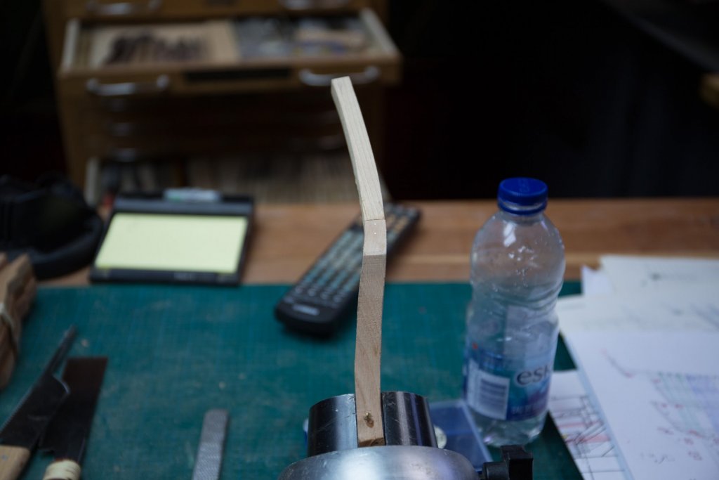
The whole structure is fully framed except above the toilet door. Even if I did not do any research, I see no reasons why this space would not be also fully frame, so I filled the void. Even if a cannon ball would not be stopped by a frame, it surely would surely be slow down, especially that there is a big reunion room behind. I replaced the dead laser guide. In addition to project 1 or 2 perpendicular lines horizontal and vertical it can also project a angular line 360 degrees and another tool is added to measure with greater ease the same elevation on both sides when tracing longitudinal lines outside or inside the hull; a laser to measure distance especially, the vertical ones. An 8 feet long square batten, almost as thick as the planking, is use to draw reference lines on the hull. Basically it is a straight line with both ends being higher than the middle. To get a regular curve at the front end, masking tape is use instead.


-
If I remember well, it is similar as using oil for small lathe. light hydraulic oil iso 32 or lower the less additive the better it is
-
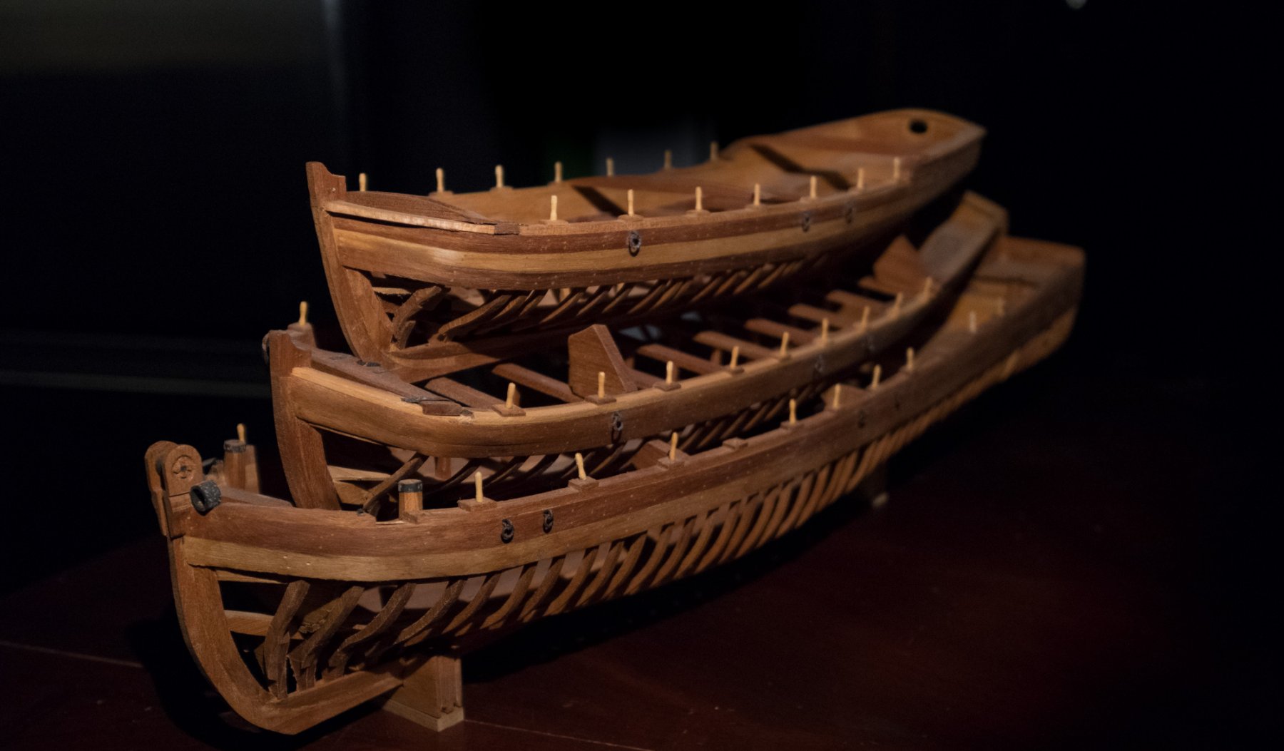
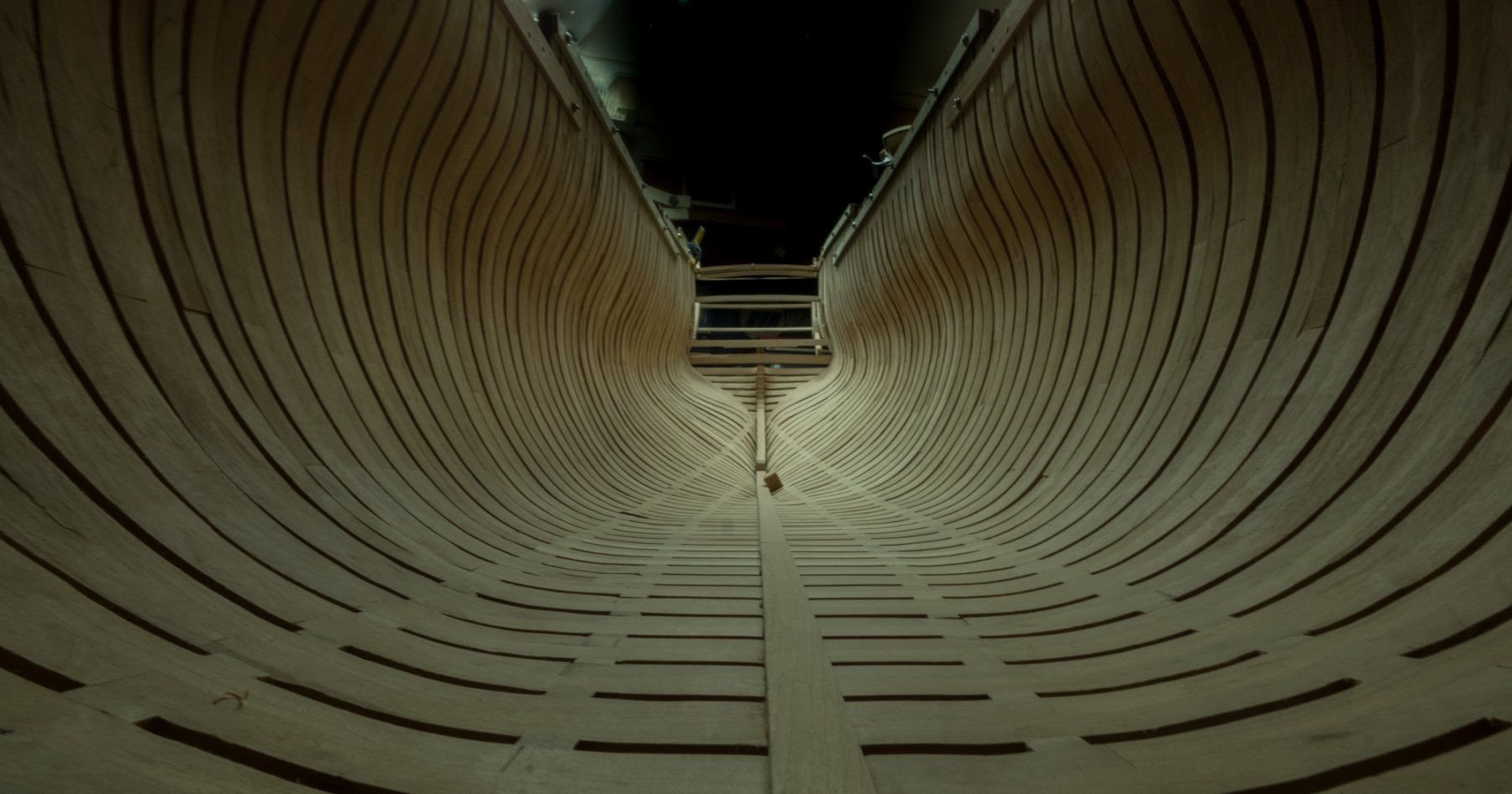
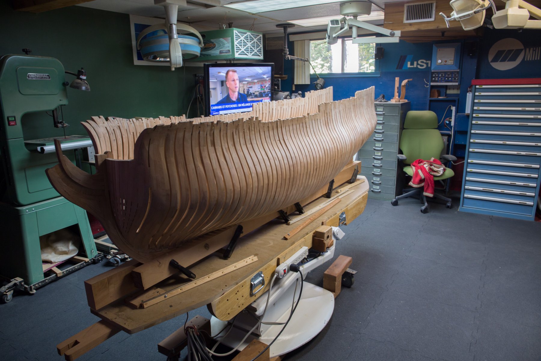
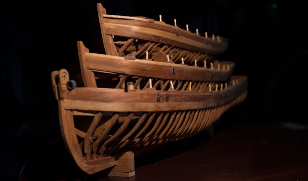
second chapter, beginning aft;


-
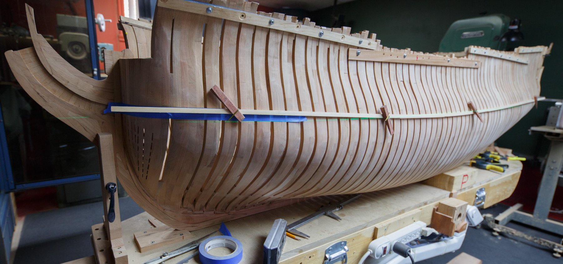
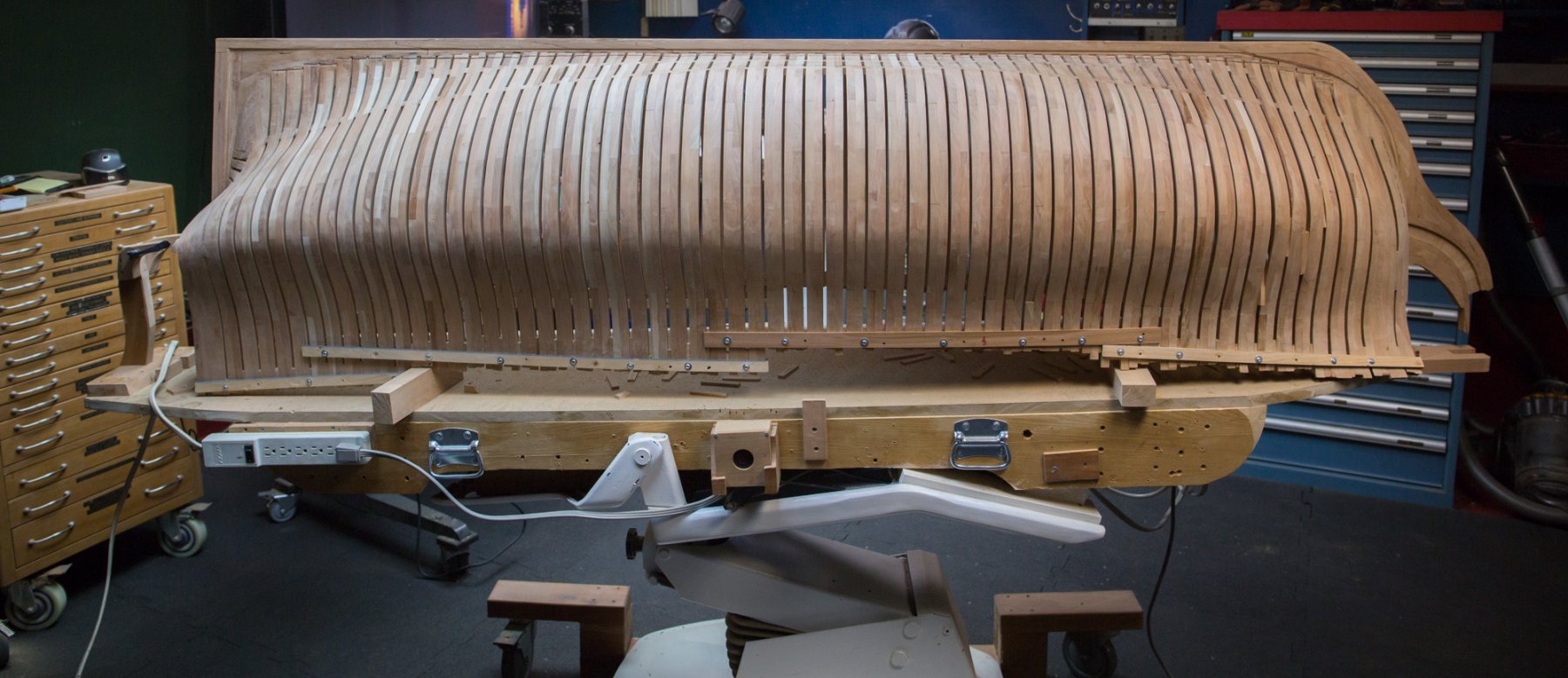
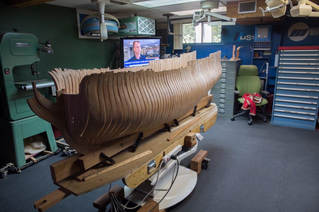
The problem of wood movement of the keel has been observed by many of us. With this build, I took sometime to observe it and it was well worth. At scale 1/24, I find it difficult to have every parts to fit always at equal distance of the center line. I have often asked myself how it was on 1 to 1 scale. It surely would be an interesting observation to do on a real one! Humidity and Assembly Pressure are factors influencing wood movement. Humidity is the smallest one. Pressure used during assembly to fit the spacers is the main one. The first effect of excessive pressure are observable on the straightness of the keel. For this reason, the assembly method used has the advantage that you can turn the keel upside down. A method using MDF or plywood to hold the frames would be useless to check the keel fairness. 1/3 of the frames front and back were assembled with no pressure, just by adding layers of frames and spacers. The middle third was assembled with some pressure mainly for the last spacers. I did some assembling and disassembling of that last third and I think that 2 factors can correct this fault : - eliminate as much as possible the pressure by reducing the thickness between spacers - unglue 1 side of spacer each 4 to 8 frames.
-
The idea of black base is perfect. A black fabric as a background could also be nice, at least for a few photos: c
- 290 replies
-
- 2
-

-
- confederacy
- frigate
- (and 1 more)
-
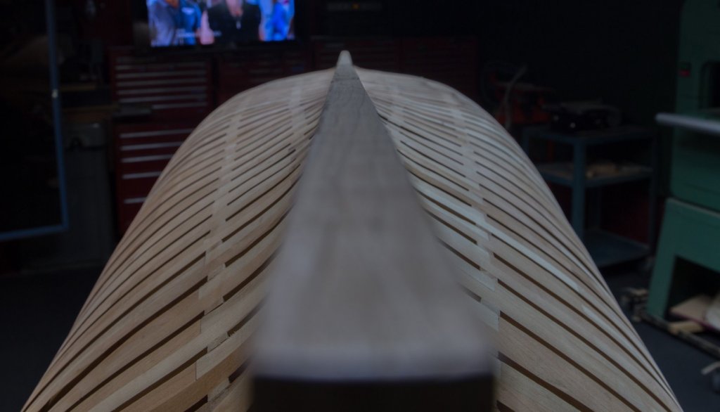
Hi Druxey, In Quebec, humidity is at his peak in autumn. In this case, assembly was made this summer up to know. Humidity is certainly a major factor but there is another big player who comes to influence this assembly : Tension. All these tensions created by the assembly of the frames are not working in the same direction. It is only the beginning of the construction and the keel was already curving. If nothing is done, the problem could amplify. Not only the keel will curve like a S shape but the keel will also twist from 1 side to the other. One way to observe would be to pull a rope between the 2 extremities of the ship and to measure parts every side of this center line… it will be off center. The good news is that at this early stage of construction, it is possible to reduce greatly this problem. This multi layered sandwich has around 200 layers which must fit in a fix length. The thickness of 200 glue layers is not calculated anywhere but it will influence the assembly pressure. Frame thickness is fix thickness in the puzzle that can not touch. The only remaining variable is the spacer thickness. But it is only when the final action will be done that the keel will retract and come back straight again with the Trussben effect; unglue 1 spacer side every 4 to 6 frames.
-
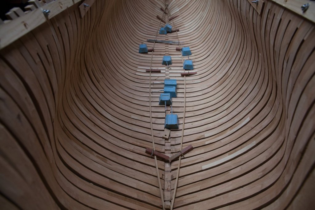
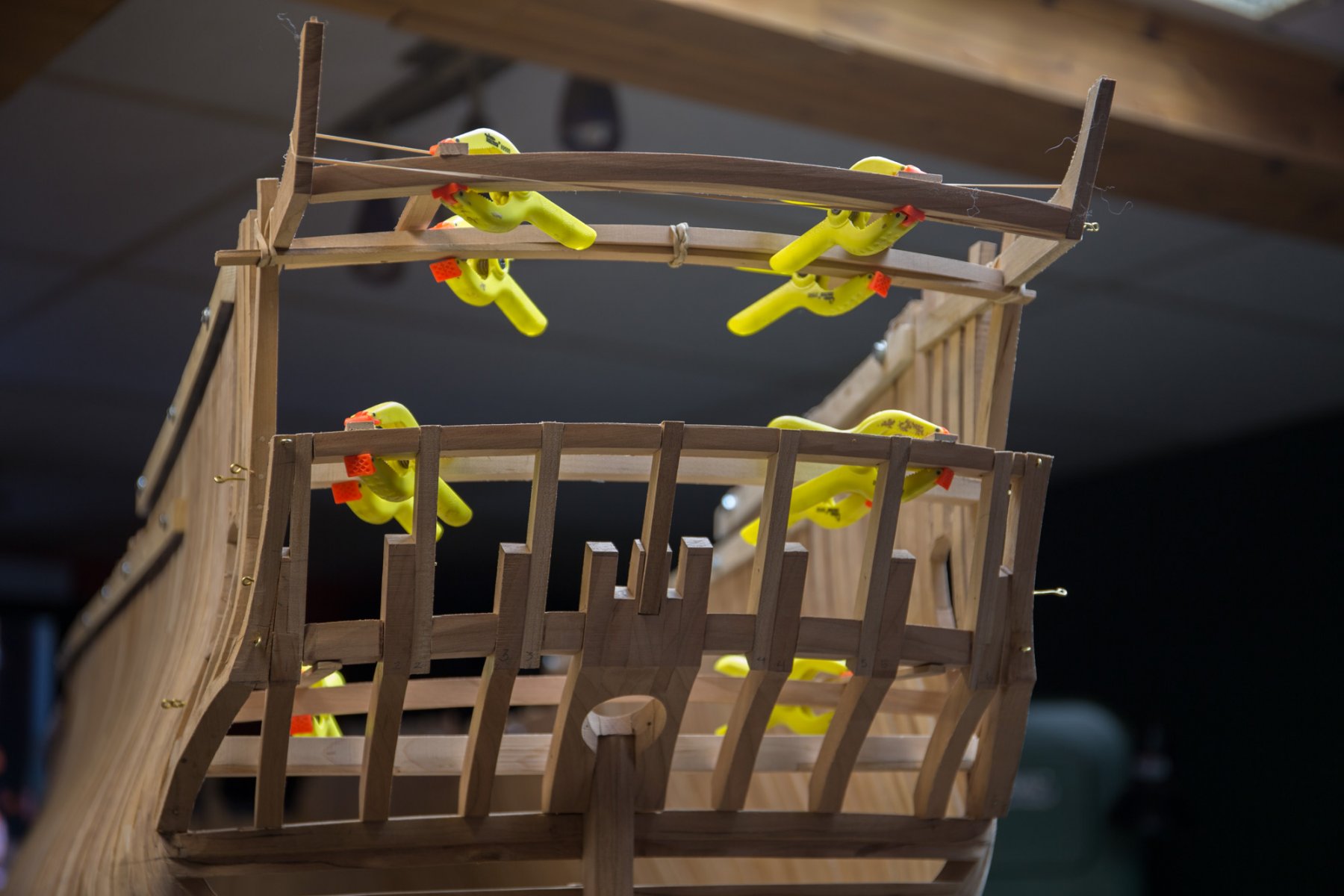
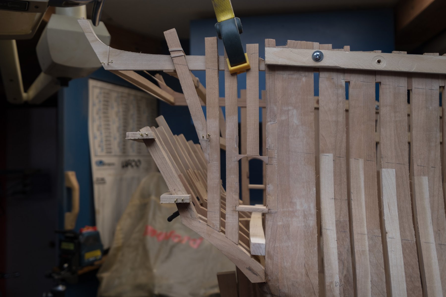
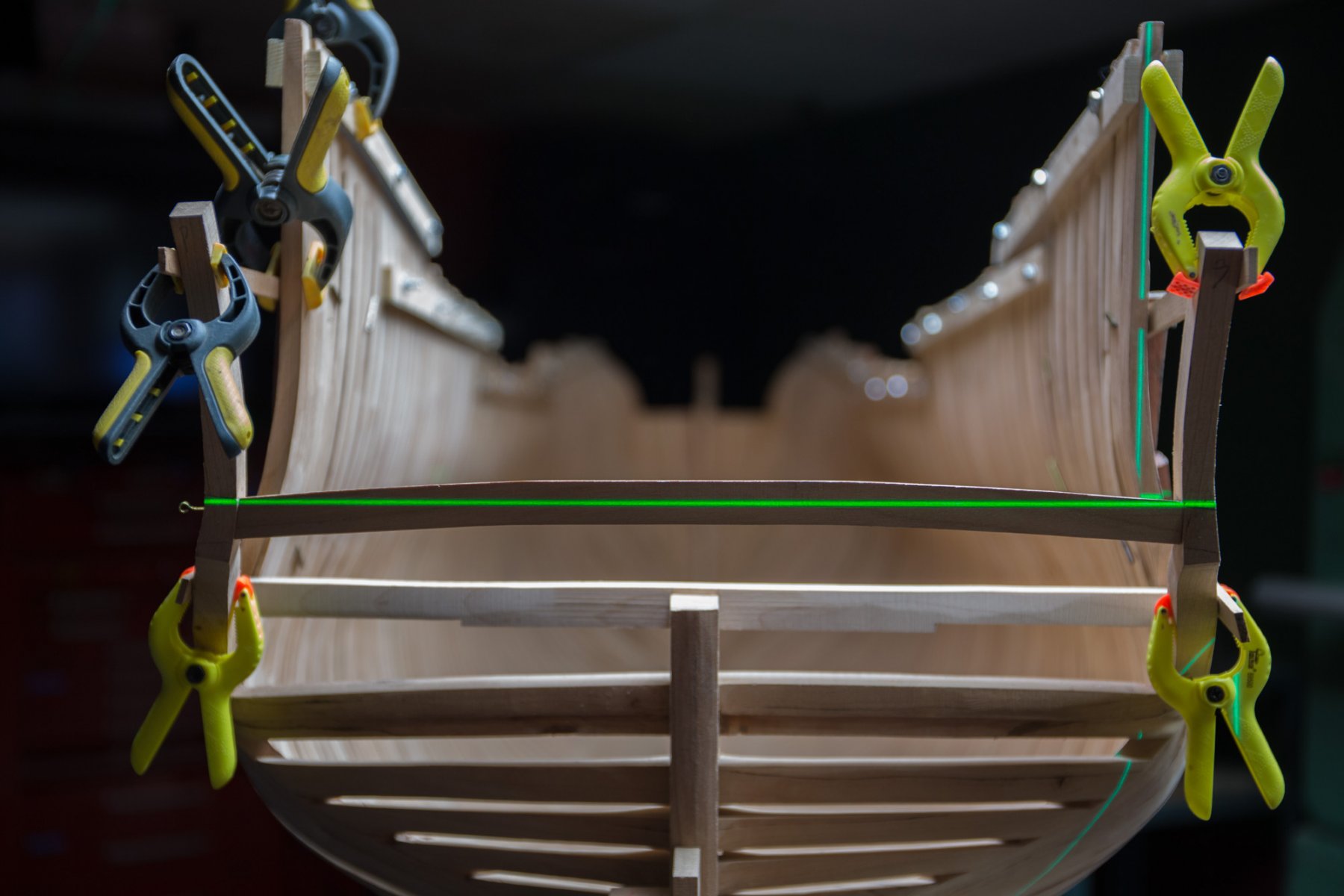
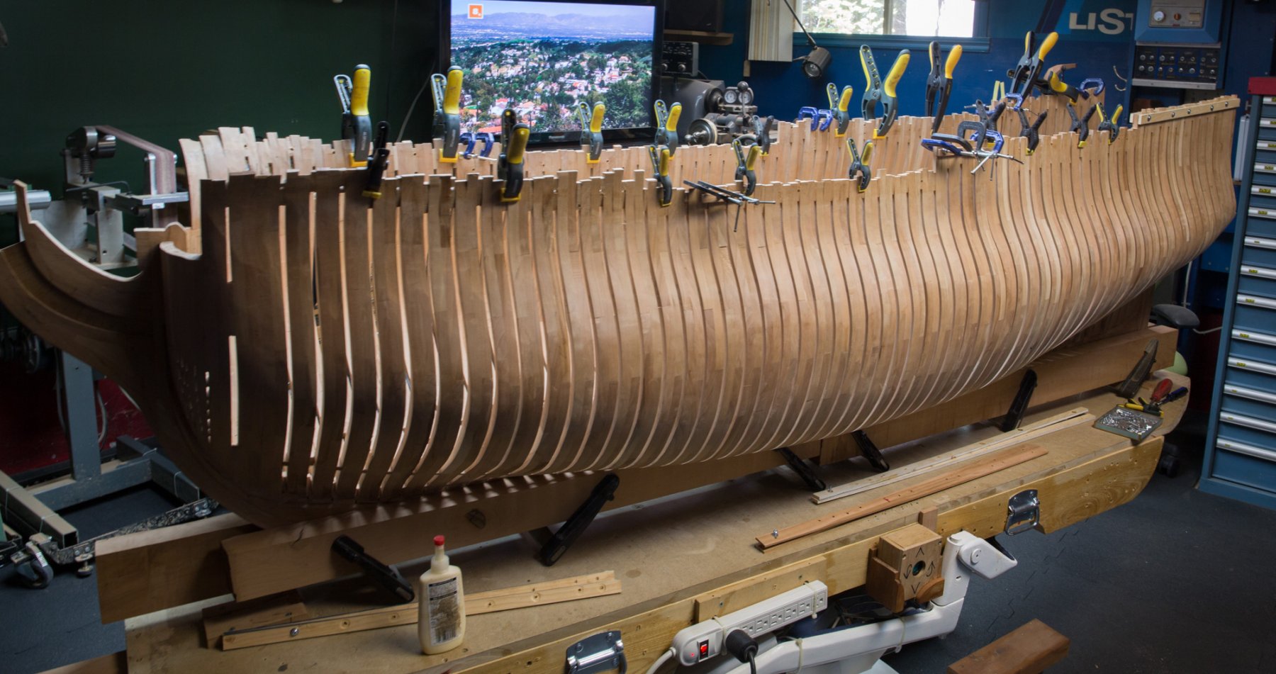
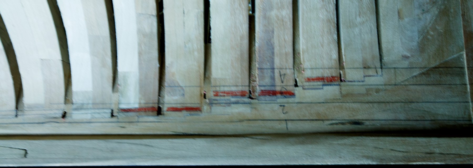
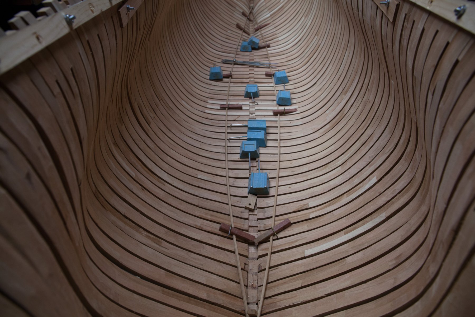
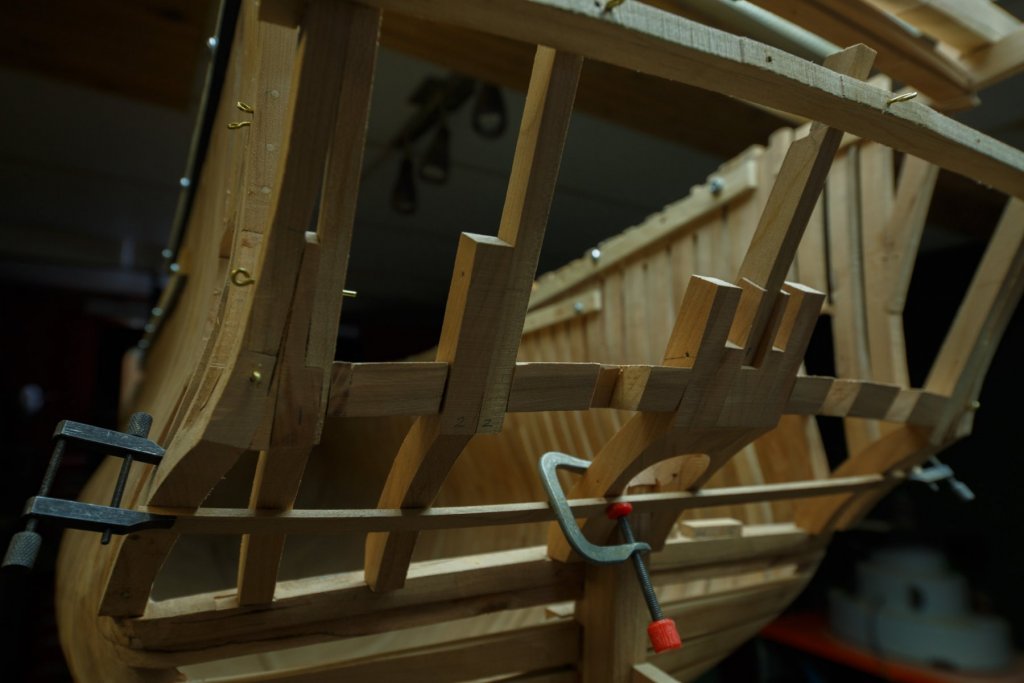
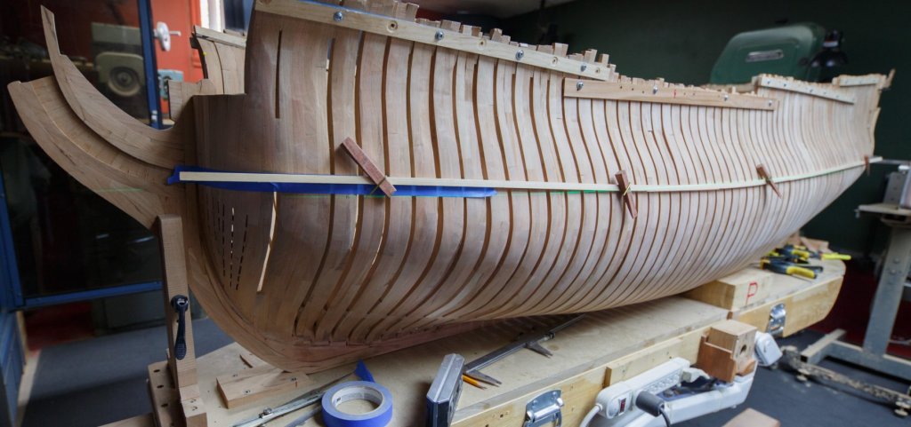
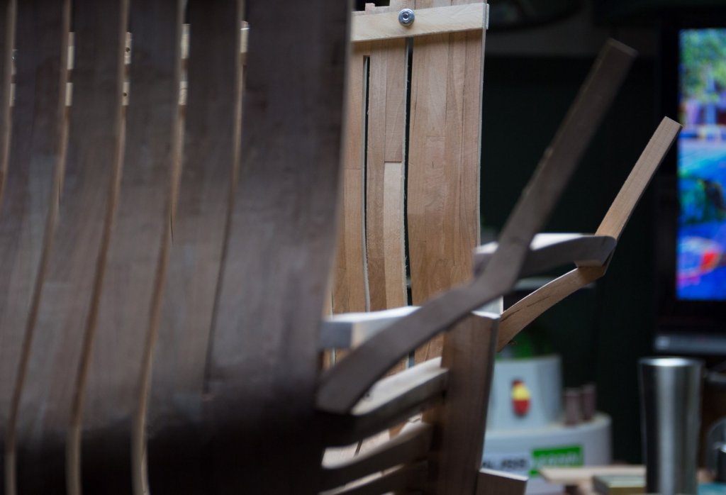
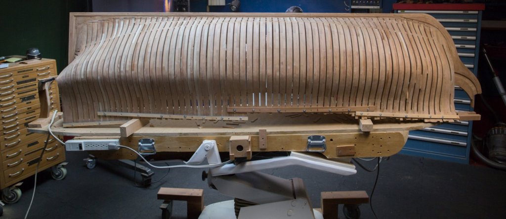
Thank you Picture explaining last post frame assembly from 1 extremity toward the middle, both side middle area in last, buffer area to adjust spacer thickness + unglue 1 side of spacer every 4 or 5 frame, 6 look like a bit too much. FUJI4179
-
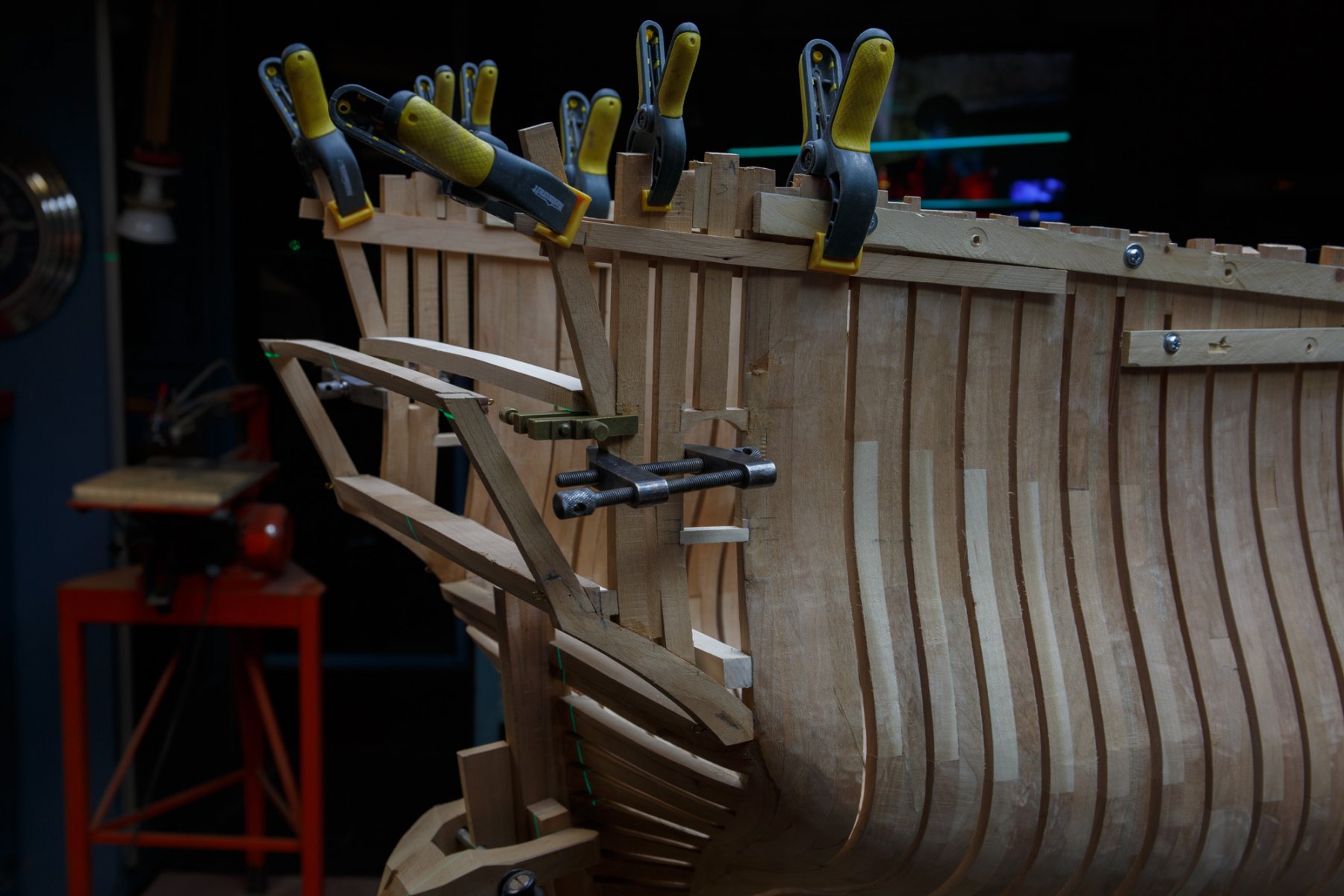
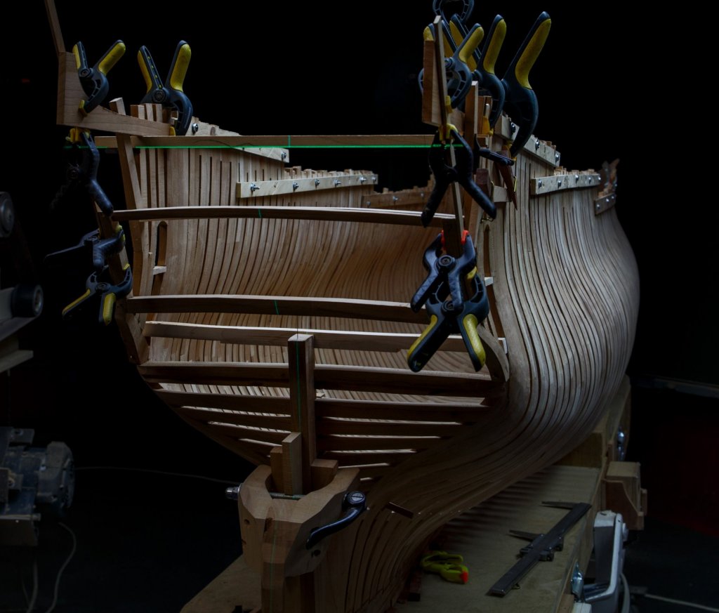
Merci Messieurs for your compliments. Rebalancing the frames I did unglue few spacers more : about 1 side every 6 frames (represented by clamps on 1 picture). Thanks to those who developped this method, it proves to be really effective. The keel was also reclamped to help it to realign. 1 other step has to be consider when assembling frames to help to reduce stress which can be then transmit to the keel. After the assembly job is completed, I think it is a good thing to check the keel assembly if there is any curve and if so it is a signal that some pressure must be release from the assembly by ungluing some spacers. With the 74, a theoritical thickness of spacer between frames of 0,225’’, had to be reduce of at least 0,01 to 0,215’’. Still it was not enough, it had to reduce from the thickness of 1 spacer divided between around 20 frames. So It would be around 0,205’’, this means almost 10% less. Is it too much??? The idea when assembling the frames is that the assembly must not to induce pressure to include spacers. If too much pressure is used, every thing will want to disassemble in 1000 parts nd this we do not want to see!

-
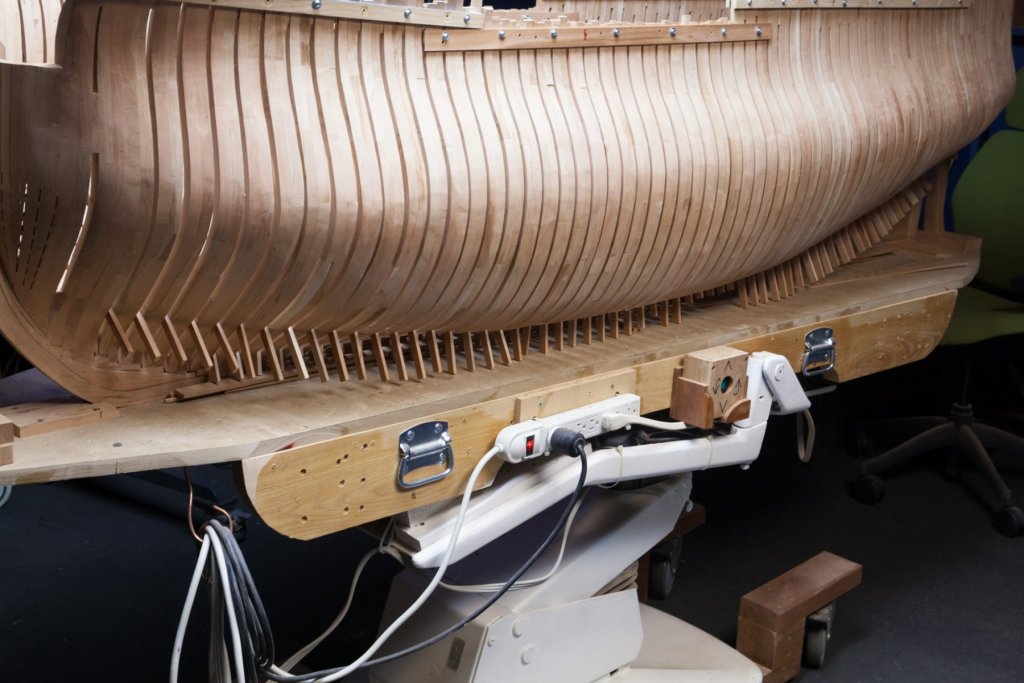
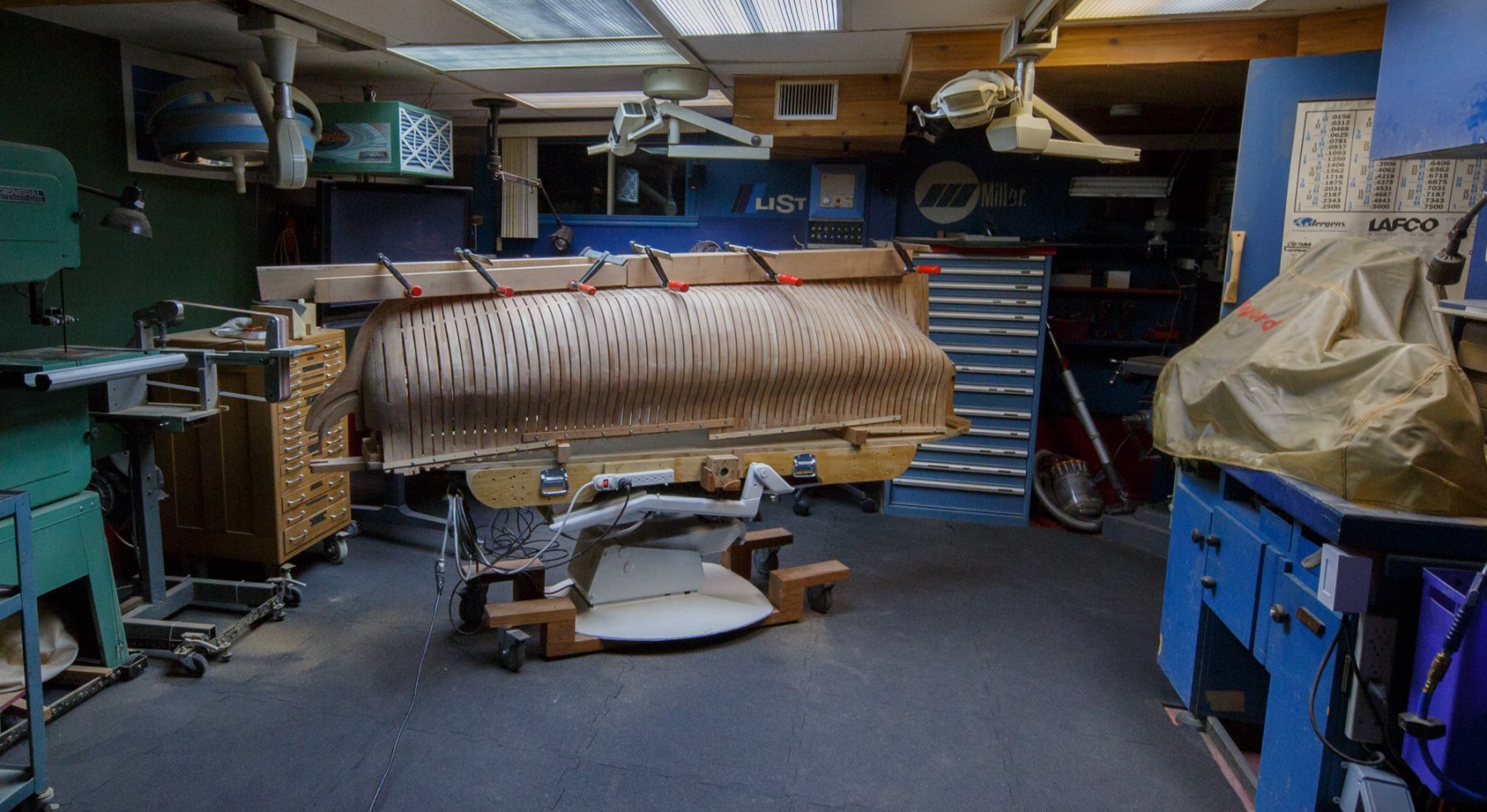
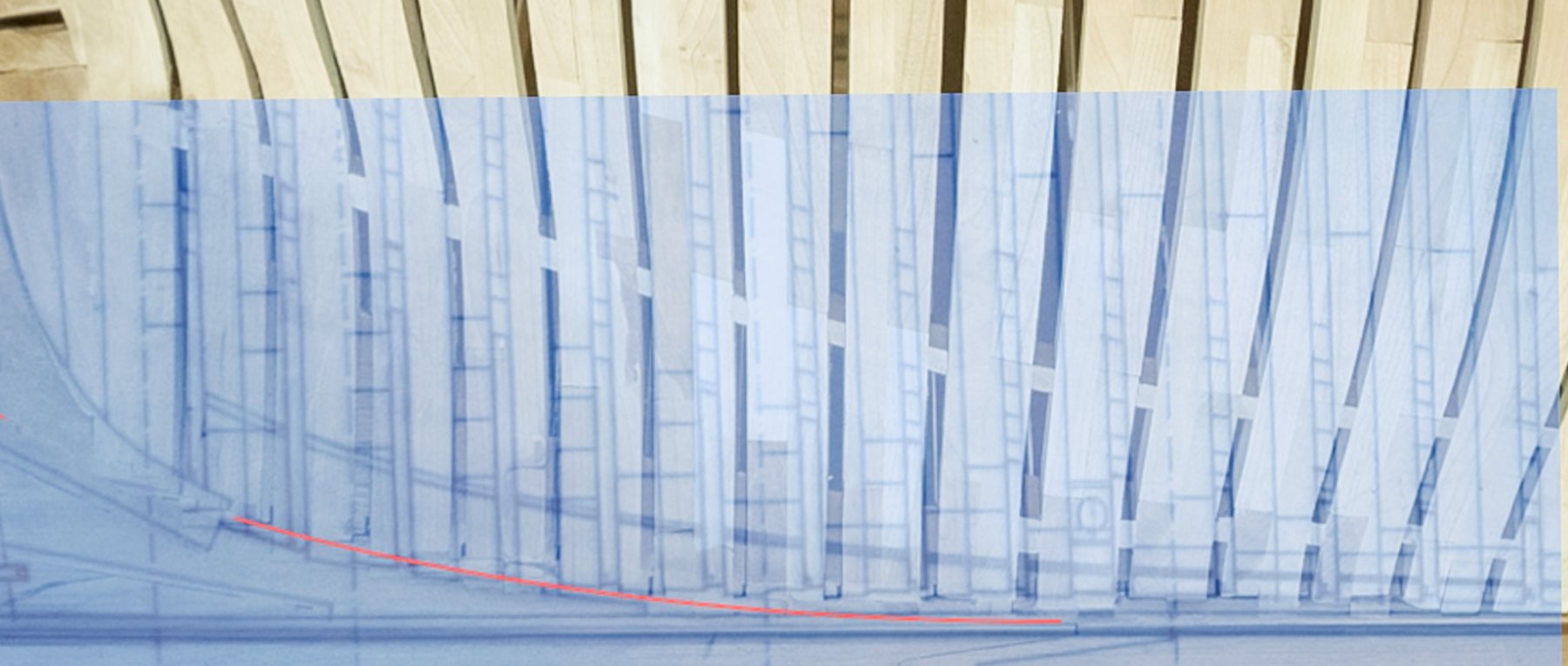
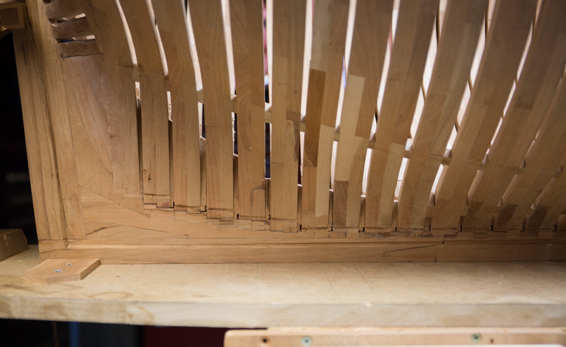
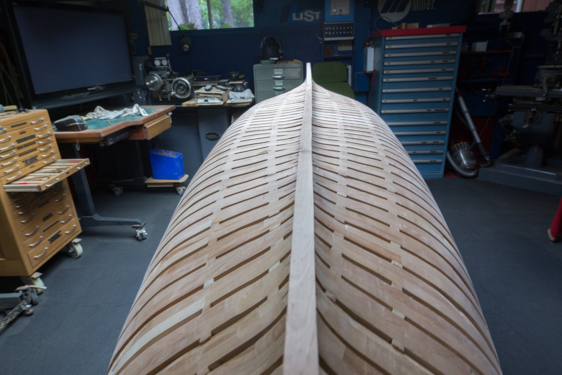
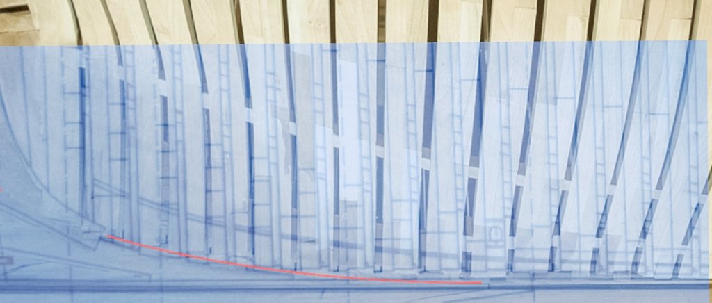
Thank you Deperdussin1910, A lot of strengths are involved in this puzzle. It is difficult to well balanced everything. The keel was supposed to be straight but it was not. The first method to unglue some spacers between frames was to try to realign the keel with 2 by 4. It did unglue some and helped to realign. I will let everything stabilize and probably unglue some others. We also see how the planking fit on the keel. Limber holes has been traced lower than on drawings and cut.


-
Dan, Sometimes the only way to know is to try. Sorry, I do not know the answer.
-
Here is an example of bitumen used in the Fleuron build on this forum. It can be mixed with other products like bee wax etc. It dries very well... as long as you do not apply too thick coat.
-
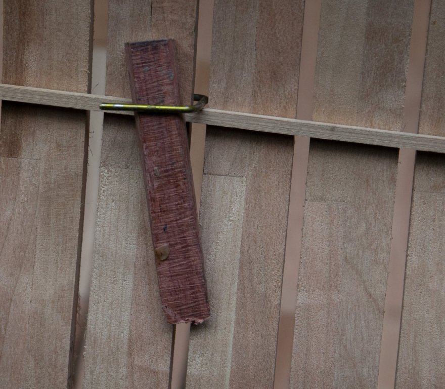
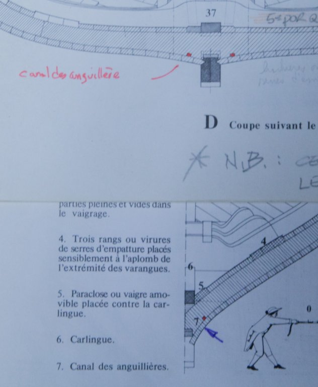
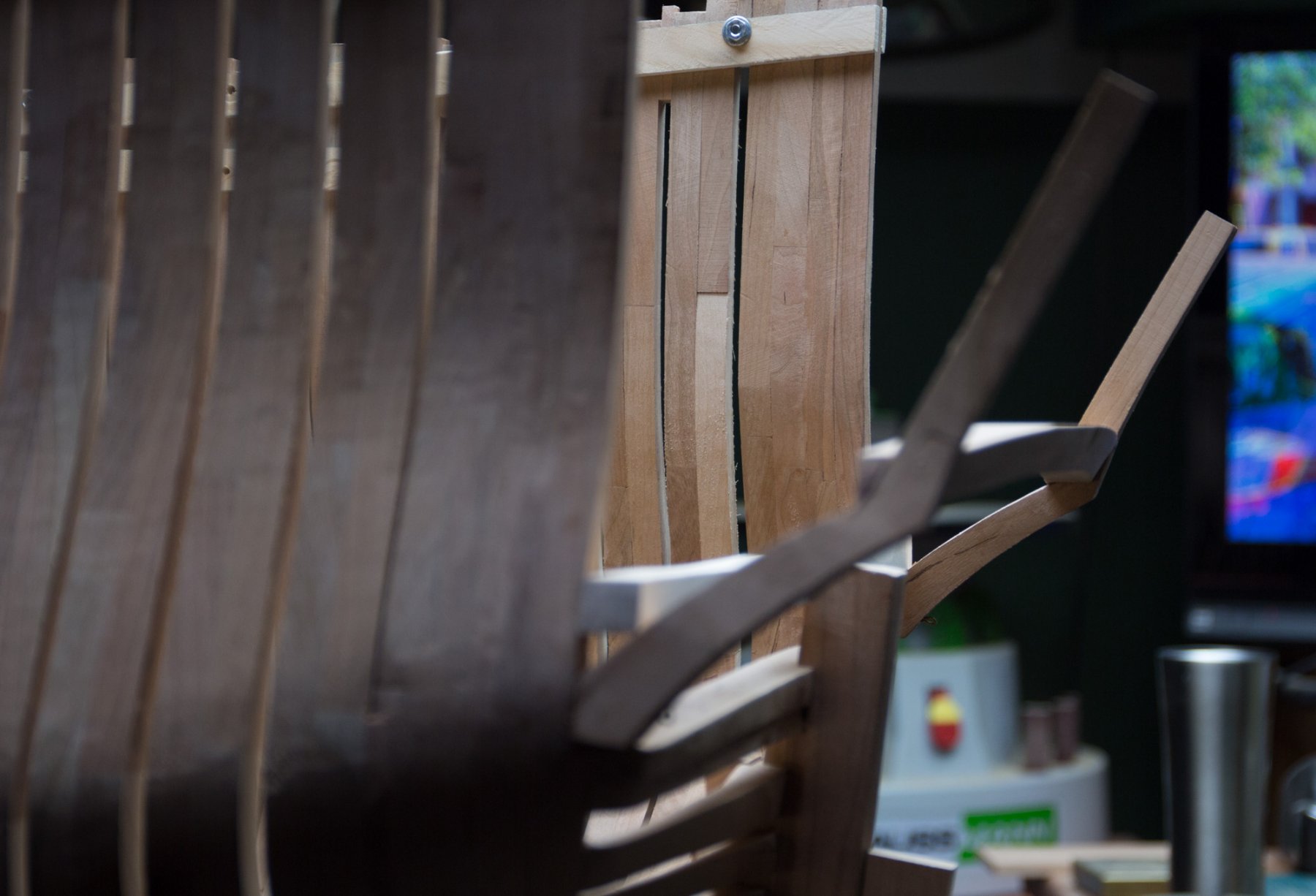
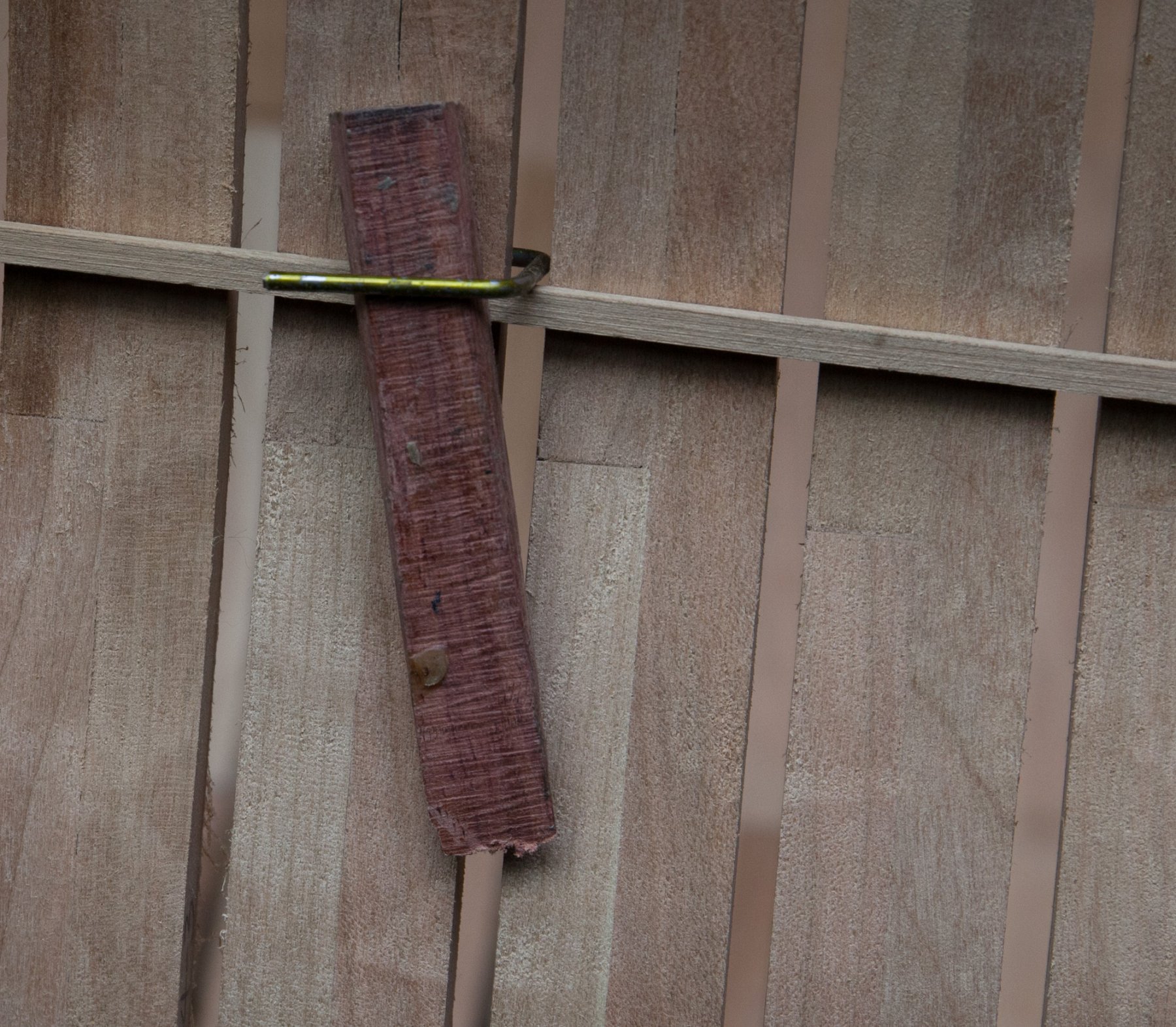
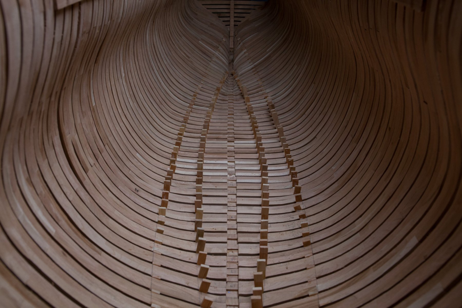
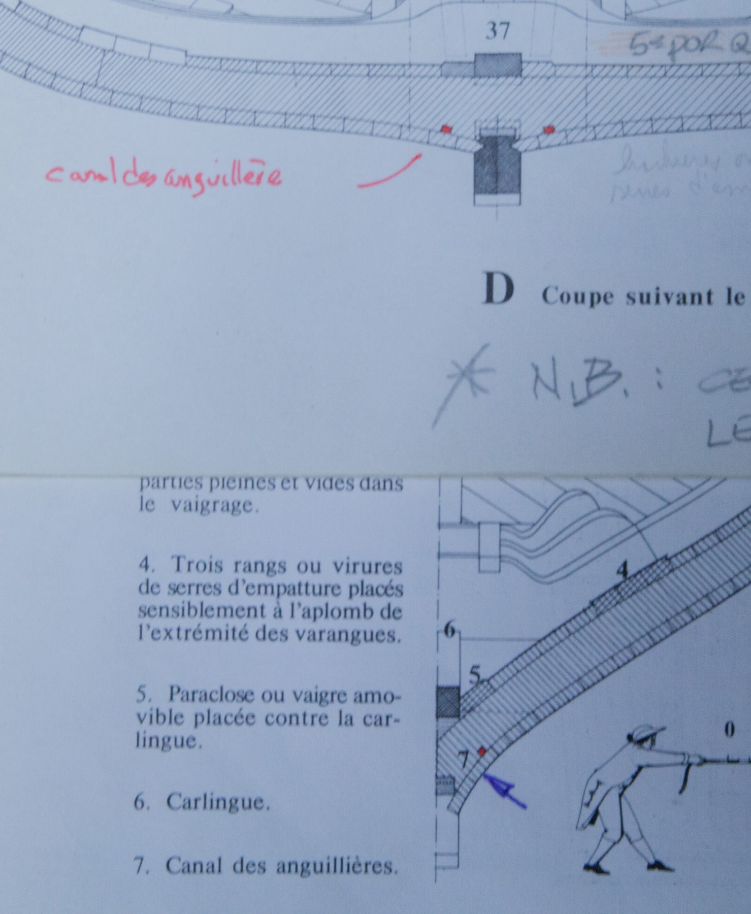
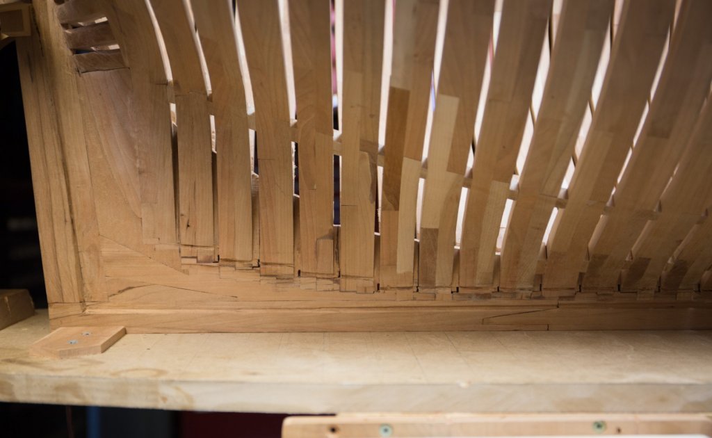
Installation of spacers between frames, 2 rows in the bottom of the ship, each side of the keel. Spacers are installed at the jonction of 2 parts. Tracing the line is made with a square plank held on frames by metal clothes rack bent in C shape, adjusted by a wedge. Boudriot, volume 1 p. 132 : the form of the limber hole is rectangular and is located under the second planking (gabord or galbord : first one, ribord or vibord : the second one), except at both extremities. Joints between planks must not be over the limber holes to avoid obstruction by oakum (calfatage) and also at the end of the planks where an iron plate is set. Above limber hole there is a removable plank (paraclose) for cleaning purposes. Pump feet are slightly above the channel. To prevent oakum aspiration from the pump, a wood veneer is inlaid in the foot of the pump on thecorresponding frame.