xken
-
Posts
841 -
Joined
-
Last visited
Content Type
Profiles
Forums
Gallery
Events
Everything posted by xken
-
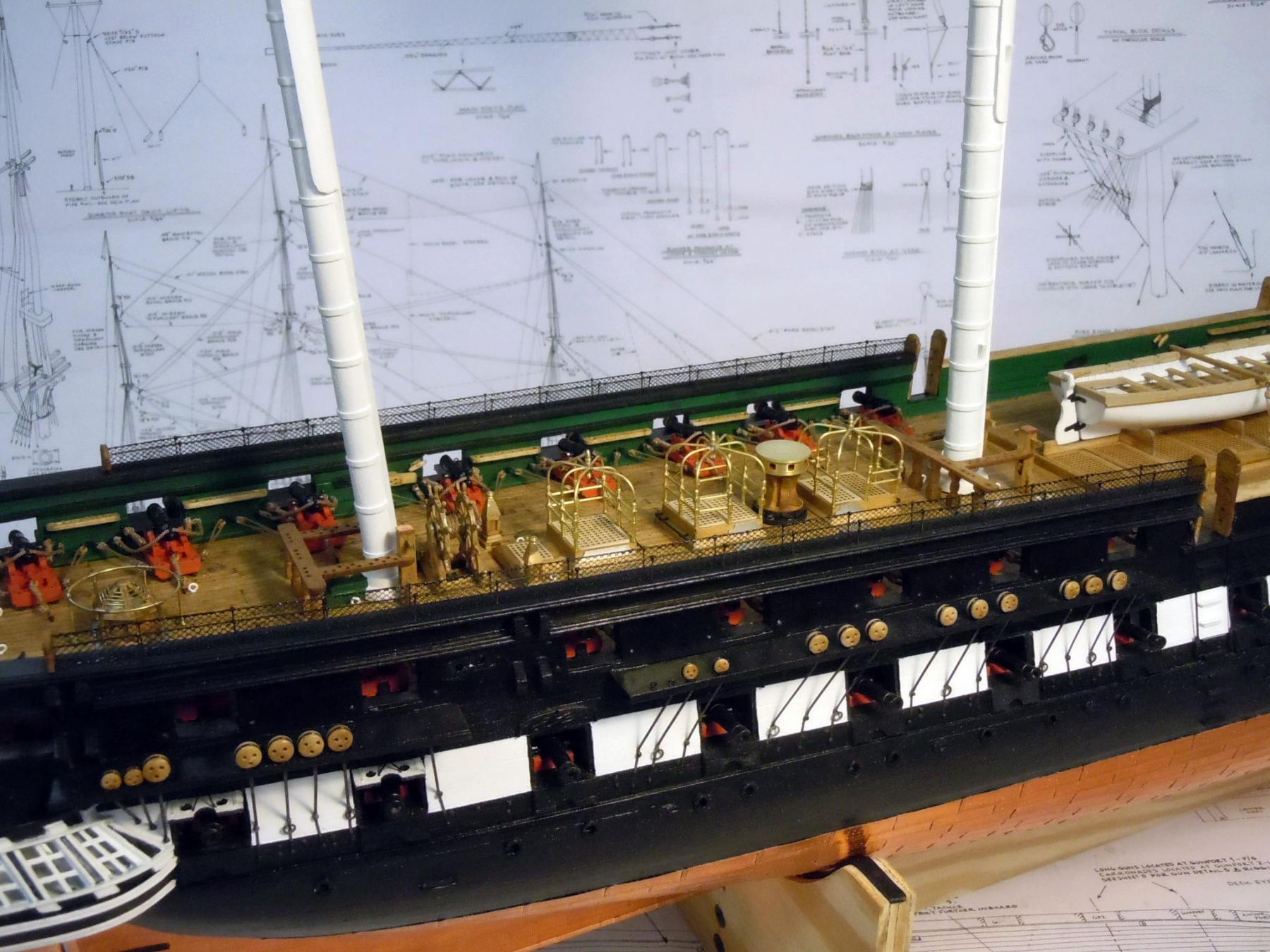
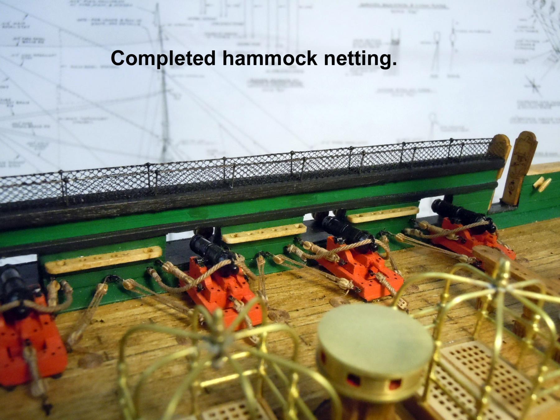
 Finally finished the hammock netting. Let me just say that doing these is slow and tedious requiring patience and magnification to assure a good strong bond between the brass rod and netting material. Here are a couple of pictures showing the aft portions. Next I will move on to the shrouds. Question: In some paintings with the ship under full sail I see a second studding sail boom at the main mast location. These are not referenced in the manual or plans, but the sails booms are referenced to add on the yards. Should the second boom be added??

-
Here is a link to my current build maybe it can be of some help; but not sure what area your specific need is for your build so start here for now. http://modelshipworld.com/index.php/topic/11935-uss-constitution-by-xken-model-shipways-scale-1768/page-16
-
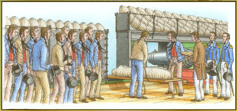
I have been out of the loop a few days helping my wife at her crafts show and then a day trip to L.A. to visit the V.A. clinic there. I received the deadeyes Saturday from M.S. thank you John and Marc for a quick replacement of these missing parts. The hardening of the wire has been explained and this technique of stretching wire or strips works for all non ferrous metals. I just clamp an end in a vise and grip the other end with pliers and give a slow gentle even pull and can actually feel the give. This aligns the molecules in a laminar flow rather than a random pattern making for a stronger harder wire/strip. Just a note soft steel wire(binding wire) can also be treated this way if necessary. Jon yes thin music wire could work, just harder to cut and file the ends against the wood boards. I am continuing with the hammock netting and thank you for the links and yes I have seen them before. I also found these drawings from the Museum and not sure if current or period, but I assume the museum would show correct images. Looking in the background can be seen the hammocks stored in the netting and they appear to be in storage bags wrapped with rope and laying at a slight angle versus a folded hammock as others show. Is there a pictorial reference showing the folded option? My lack of nautical knowledge is rearing it's ugly head again. Back to netting framework.
-
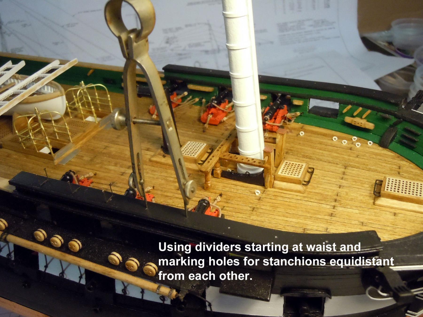
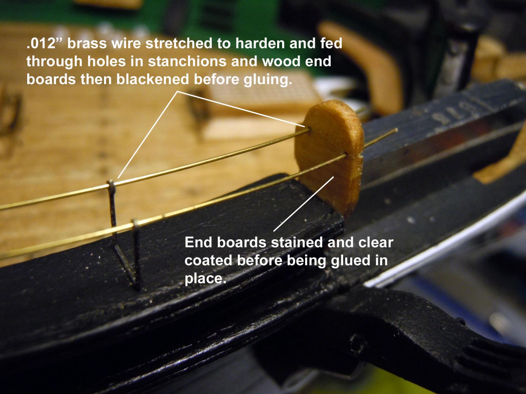
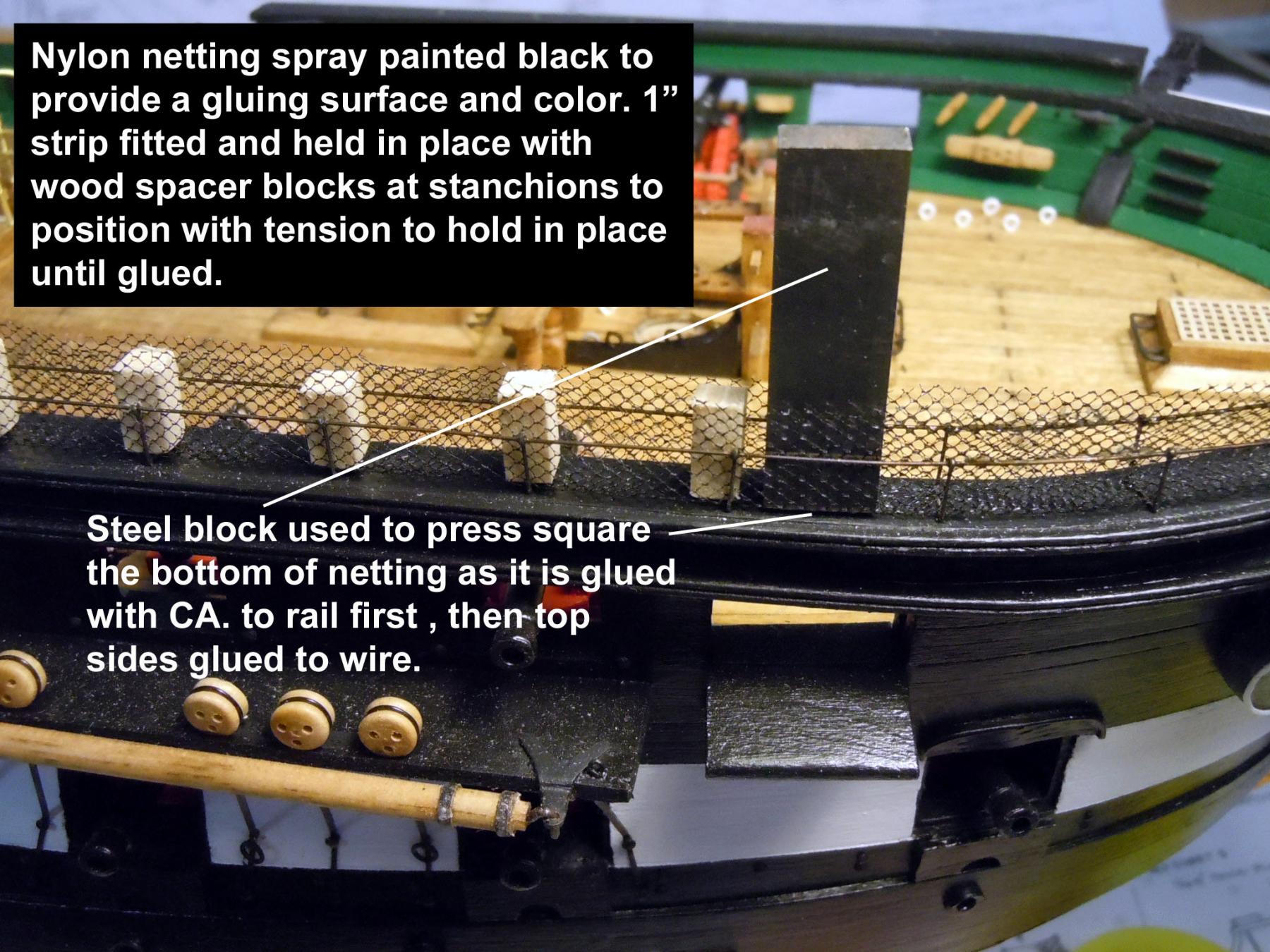
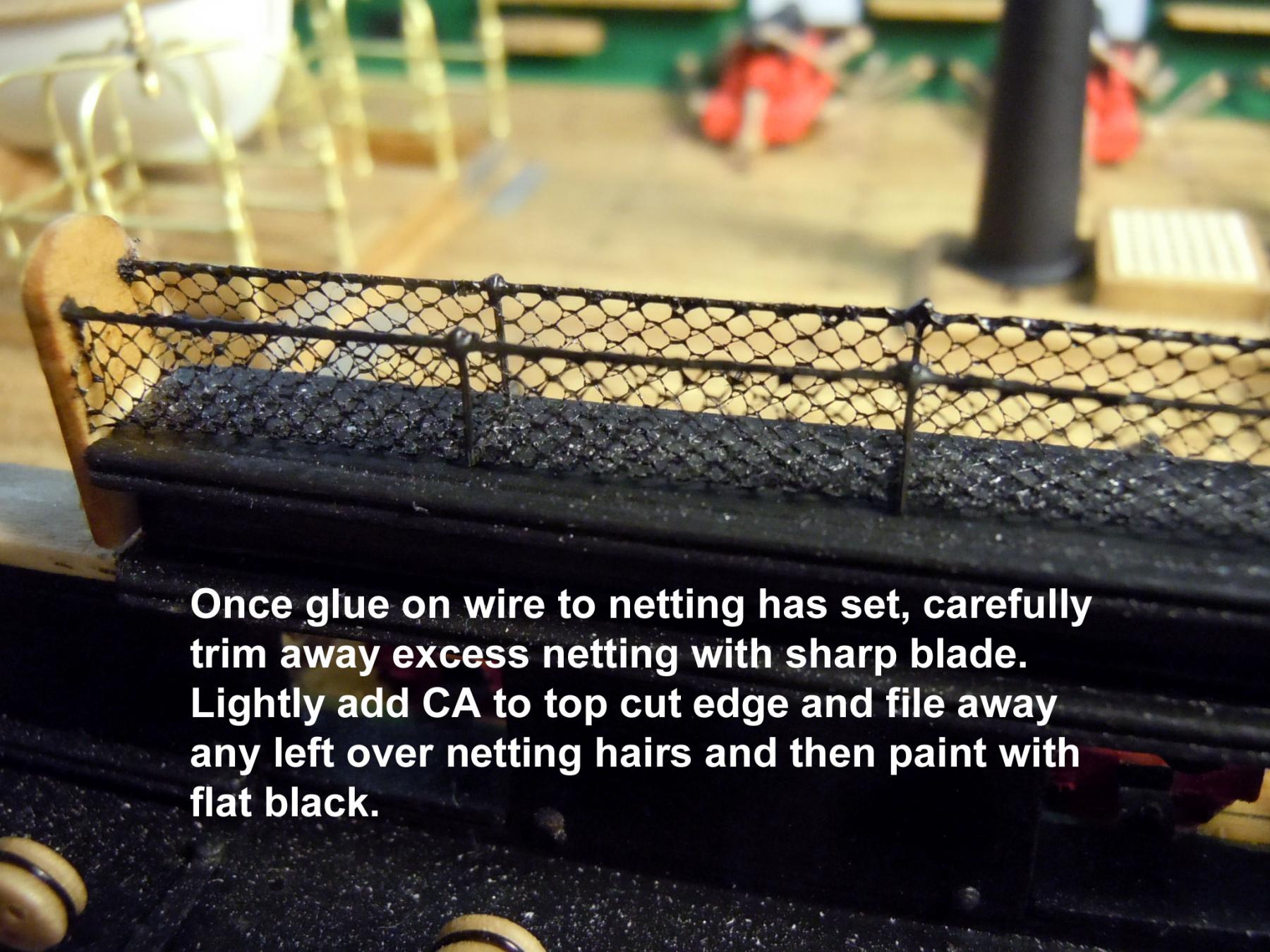
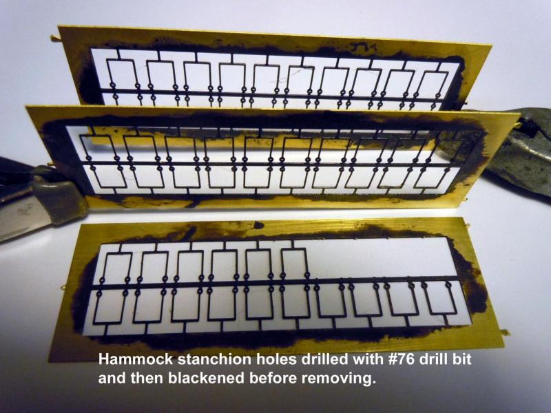
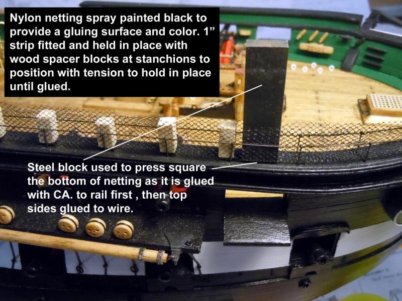
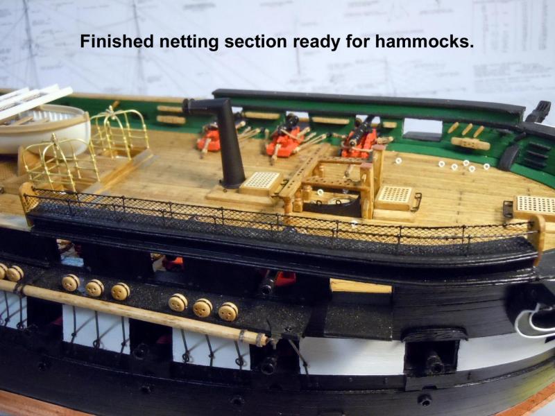
Happy Thanksgiving to all! I moved on to the hammock netting on the rails. First I painted the fine nylon netting with Satin Black paint while suspended on a paint stirring stick so that both sides could be sprayed lightly with care not to fill any of the openings. The reason for this was because no glue will stick nylon effectively and by encapsulating the webbing the glue will hold. I also drilled the holes in the stanchions with a #76 drill bit and then blackened the stanchions while still attached to the carrier sprue. I then located and drilled all the hole locations in the top of the rails using small dividers to assure even spacing and worked from the waist to the bow and stern. The rail boards were stained and clear coated and glued in their respective locations with holes drilled to receive the wire spaced apart like the stanchions. The stanchions were glued in place perpendicular to the rail edge. I then stretched a length of .012" brass wire between pliers to harden the wire to maintain stiffness; cut two lengths and fed them through the board and stanchion holes. All stanchions were then adjusted for squareness and then the wires were blackened and once dry all glued in place. I decided on using wire rather than thread for a stronger assembly, especially with little fingers. Next a strip of netting 1" wide and the needed length between the boards was cut. Carefully the netting was formed into a "U" and indexed between the stanchions. Lengths of wood blocks were cut to press fit and to hold the netting in place at each of the stanchions. Then starting at the bow and using a steel block the center of the netting was press fit against the rail top and glued with a drop of CA and using the steel block edge to press the glued netting in place to form the bottom inside edges of the netting. I slowly worked each section between the stanchions first gluing (CA) the netting bottom in place and then the top edges assuring the top glue joints between the netting and wire were secure before moving to the next section. Once finished and the CA allowed to set completely I used a sharp blade to cut the excess netting away using the top edge of the wire as a guide and slicing to the outside against the wire. I then very carefully added CA to the top edge again to assure a firm glue joint. Once the CA was dry the top edge was painted with Flat Black paint. Here is an overview of the starboard bow portion completed. Now to the rest. I am also pondering the need for the hammocks to be added. I did buy some White Sculpey, but now that I see the netting in place I am wondering if they would not be a distraction. I also have not seen a photo either vintage or current showing them in place. Any thoughts from others on these would be appreciated.


-
Darrel, I still have not made the final decision yet on the sails, so I am covering my tracks just in case I decide to. At this point, I may now have a couple of scratch builds for the local Maritime Museum. No final decision on their part yet so I am just going with the work flow and see what happens. I am assuming that their time right now is occupied with getting the building built first.
-
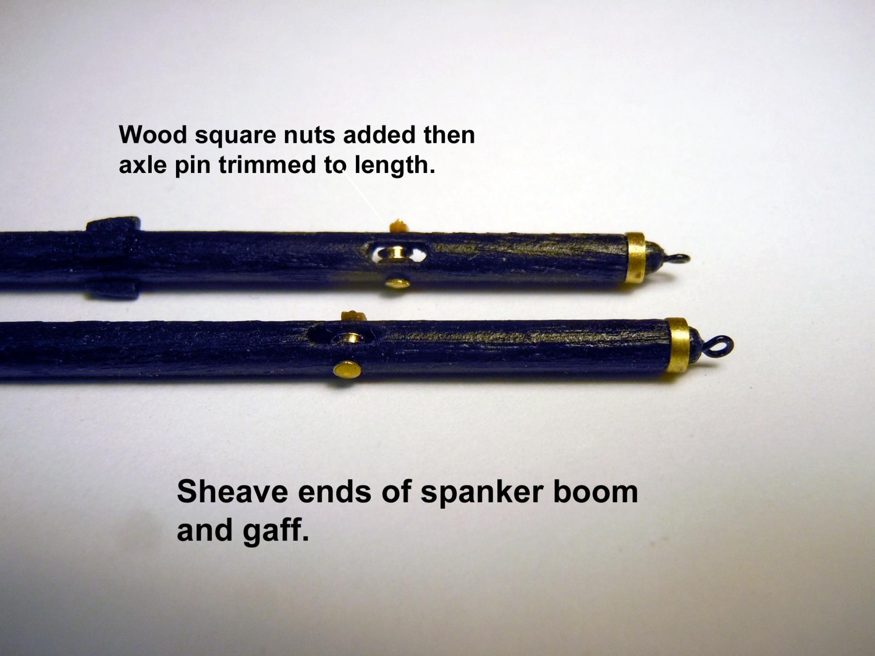
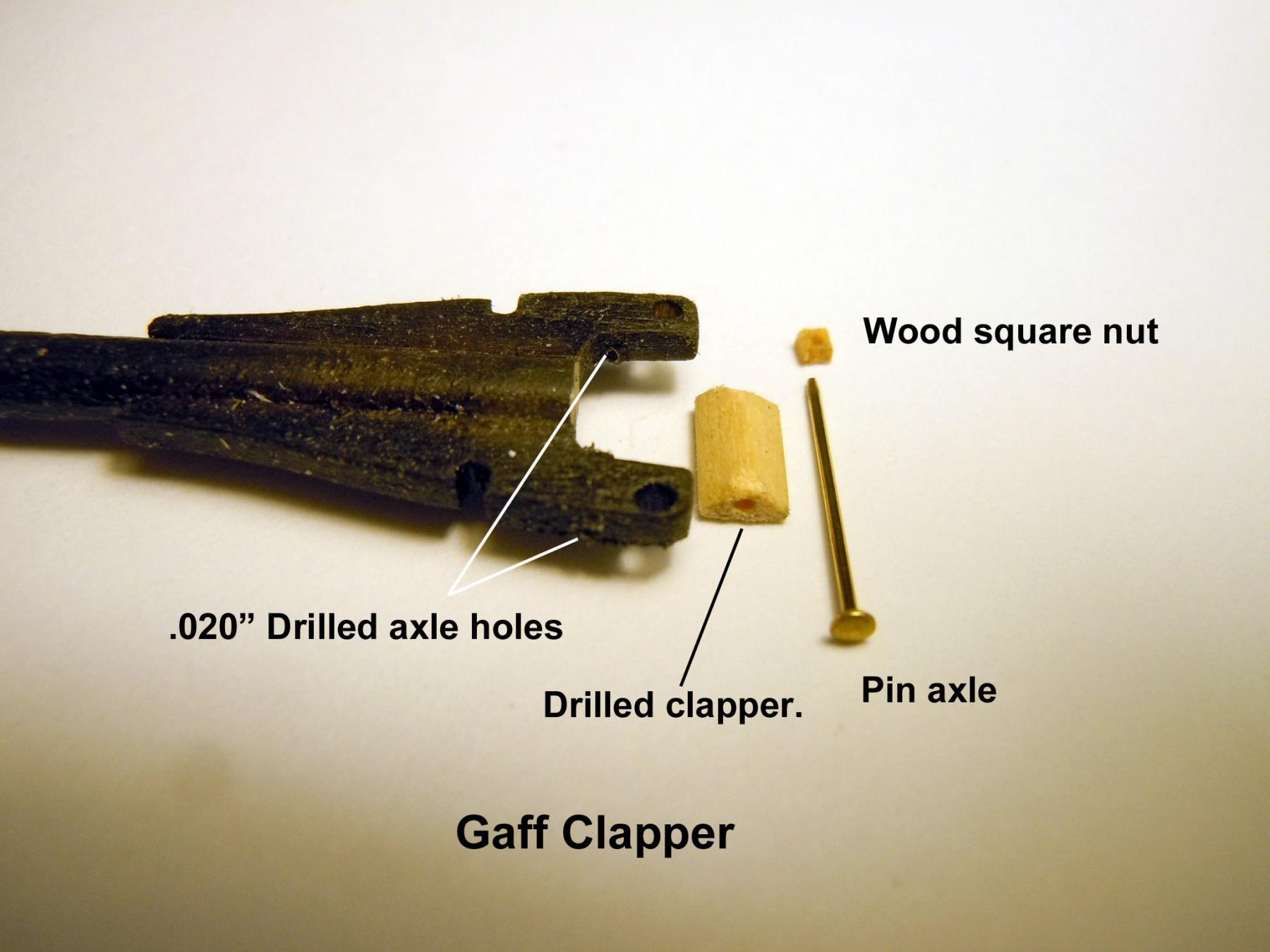
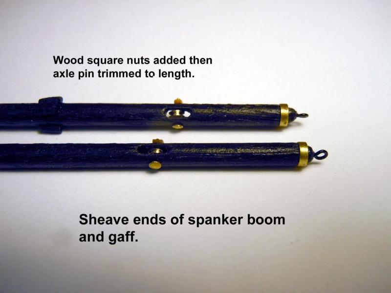
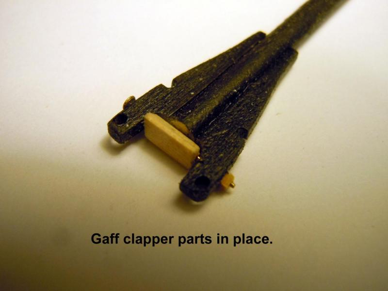
Finished up the spanker mast, boom and gaff. I had to do a little detective work to fiquire out what a clapper was on the gaff. Once I realized what it was I made it the way I think it should be and rotate as well. I still need to determine how the boom and gaff are attached to the mast. For example is there a "parrel" involved or just rope on the gaff? Rope just on the boom? Hopefully someone with more nautical knowledge than I can share the answer. I also broke down the three masts at the caps which were not glued in place as I thought I had. Good thing I write notes to myself at times. They say memory is the second thing to go! This was done to start on the shrouds only to discover that I was shorted 3/16" deadeyes and the complete pack of 60 1/8" deadeyes was not included. John at MS says they will be in the mail ASAP. Now I will move on to the hammock framework while I wait for the deadeyes to arrive. Here are pictures of the spanker mast, boom and gaff.


-
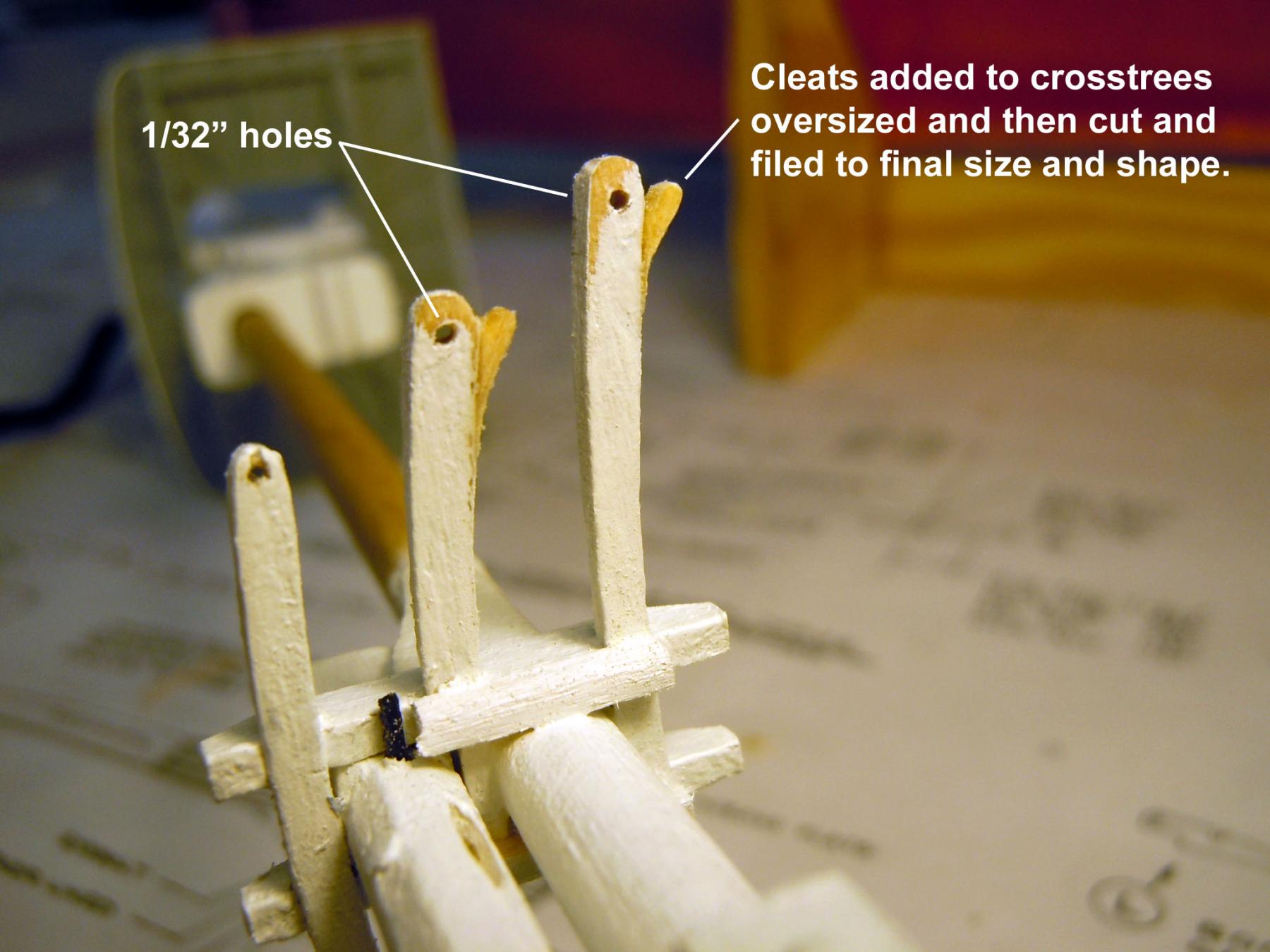
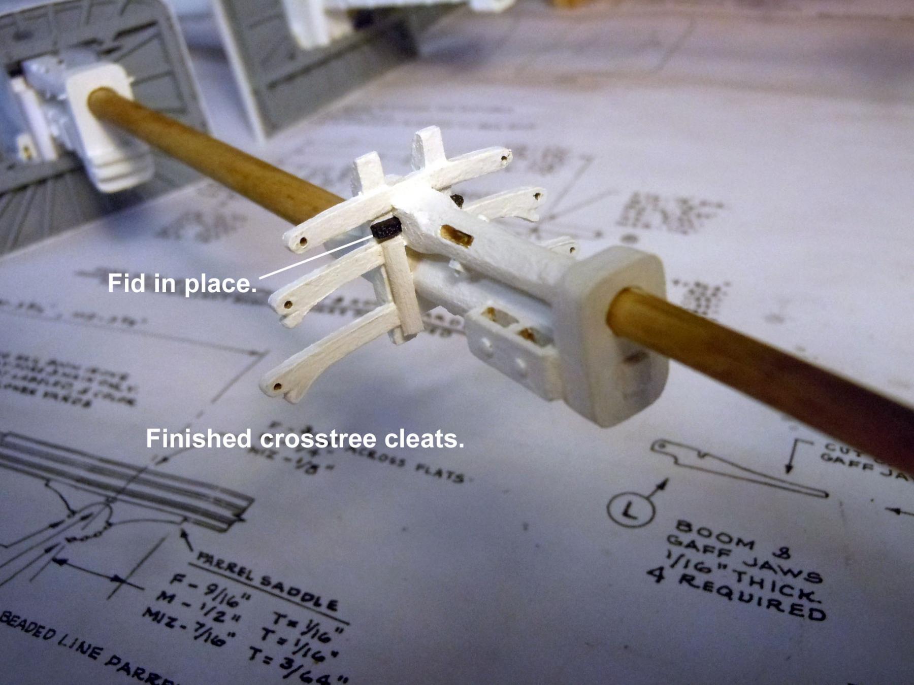
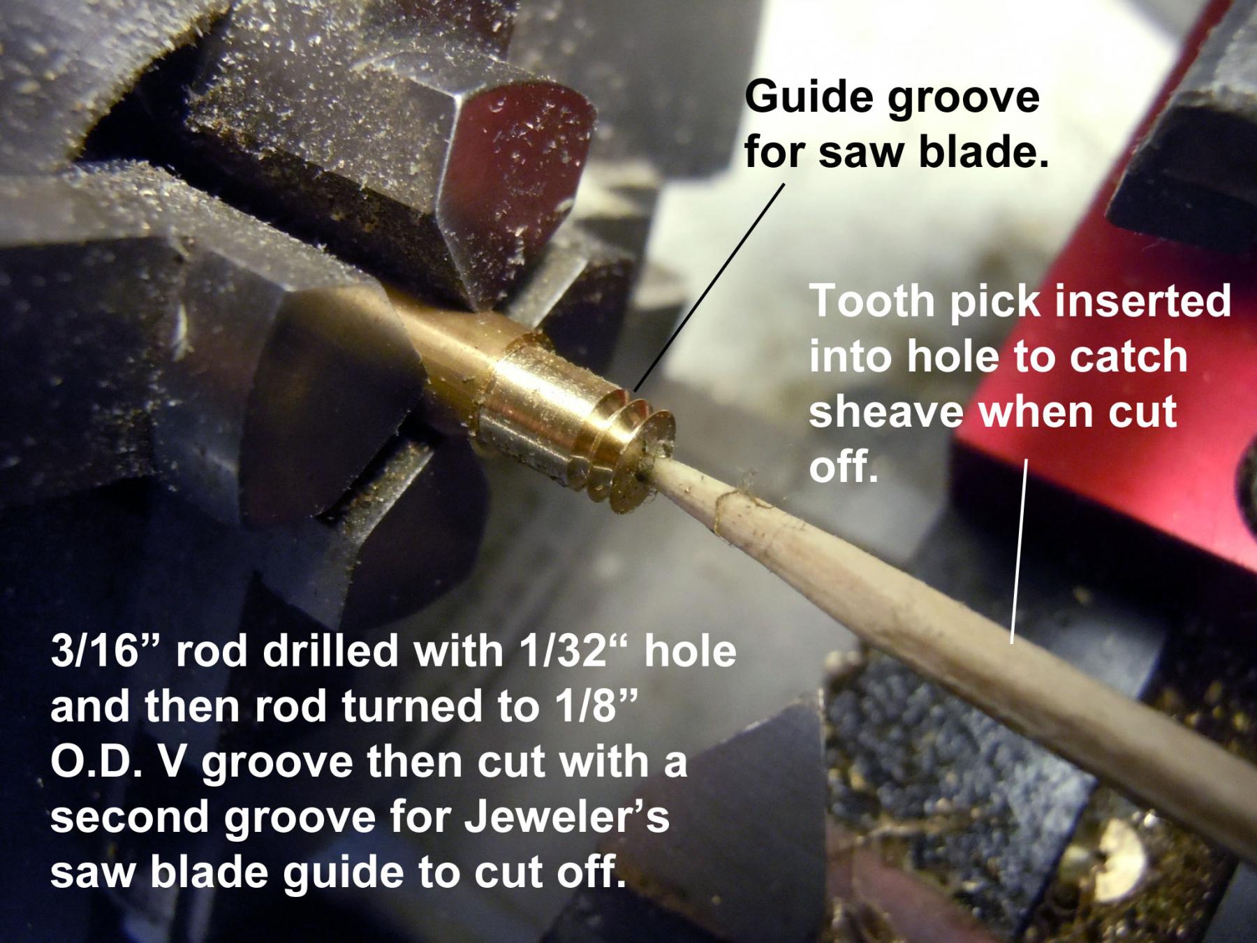
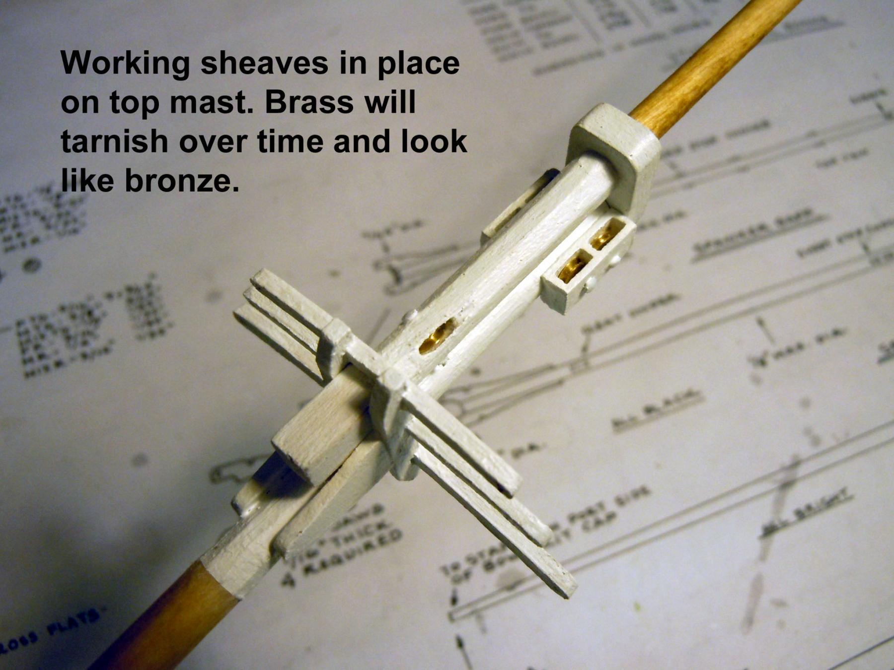
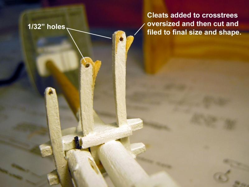
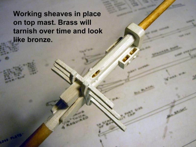
Back to ship building after grandpa duties and some fence building at my daughter's home. I finished up all three of the masts and adding the sheaves in all locations. I added a couple of pictures of the cleats on the crosstrees that were added over sized and then cut and shaped to the final sizes. I also shaped and stained the spanker mast. Next will be the spanker boom and gaff; then the fighting top deadeyes and other fittings to be located on the masts.


-
Not getting anything done on the Constitution but having a great time with Grandpa duties with my twin grandsons Alex and Tyler now 5 months old and potentially future ship builders. The Constitution when completed will be at their house. Back to Grandpa duties continue....ship building will resume Sunday.

-
Darrel, I really miss all the resources I had back in Ohio; where I live now is a wood desert. I use to make regular runs to Keim's for wood stock. Yesterday was an interesting day; my publisher emailed me saying that my book's first edition is about to sell out and asked if I wanted to update it for a second edition. I suggested that we fix the publishing errors on page 38 and that I add a chapter on working with brass as related to ship building since I had just made a presentation at the NRG annual conference on that topic. I now have a July deadline for the 2nd edition production. All the contractual materials are in the mail to me. Now if that was not enough, the local Maritime Museum contacted me about building a couple of models for them; a abalone fishing boat that was used in the area here and a topsail schooner that worked the local central coast similar to the Californian that is at San Diego. Just in the earlier stages of conversation at this point.
-
Kurt, you are being kind but absolutely correct in your assessment. Jon, I did have one that was used for the lower masts that planed perfectly then the rest are best as Kurt suggested. The one I purchased was Popular and it works well compared to the others. Kurt, I may try your suggestion on the lamination technique. When I did the spokes for the Model T I used hard Maple which turned very well and held detail and was easy to carve with a sharp knife. I may have to root through some old boxes to see if I have any left over.
-
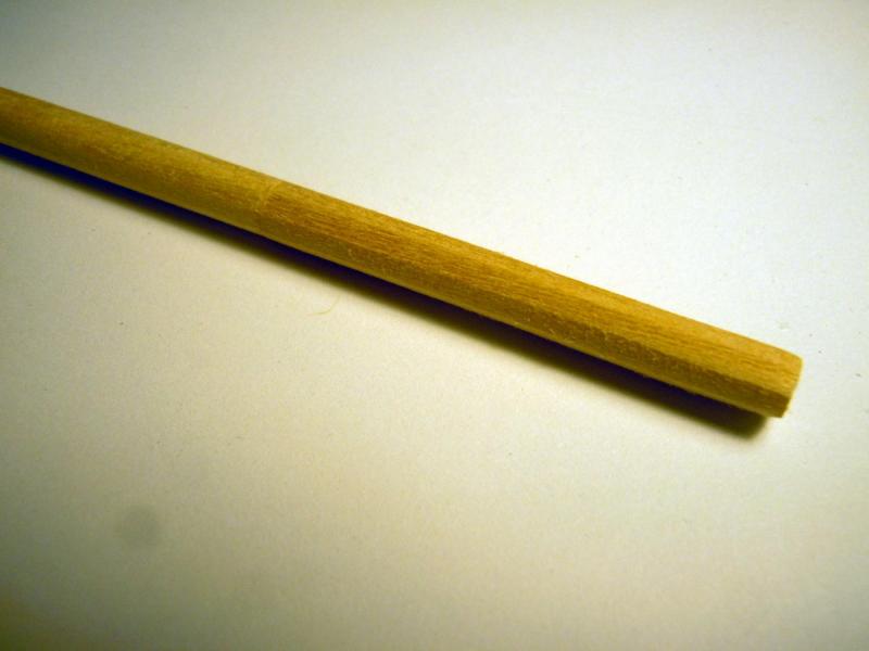
Tom, yes they are and yours will be just as tall when you get to them. I have found the kit supplied dowels a bit of a challenge to work with when shaving with my small plane with one side splintering out instead of cutting even using the sliding motion of the plane. Forget even trying to turn on the lathe. I found that I had to rough cut close and then finish tapering by using my hand held T sanding board and 150 grit dry sandpaper to final shape. Then smooth sand with fine lady finger nail files from the local drug store. Will be taking inventory of the yard needs and may purchase new ones for them. Anybody else have this issue?
-
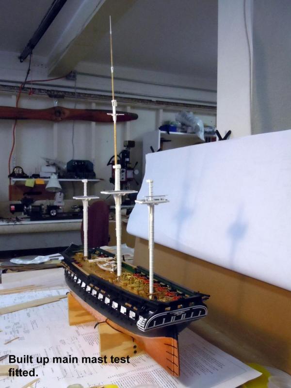
Main mast standing tall at 32" high. I have been busy with details on this mast using the Navy Yard drawings for details not clearly explained on the plans. Just a note on the drawings that I noticed was the indication of the rope lead ins where the sheave slots are located. These are the oval shapes on the drawings. Here is the mast test fitted. Following are a series of mast details that were added after the main mast portions were tapered to size. Note that there are larger sheaves that are at the base of the masts. Now onto the foremast.


-
Darrel, yes after I was working on the tops I realized that I probably should not have glue the caps on. But as I mentioned to Jon what I will do is a surgical saw cut just below the cap using a 0000 Jeweler's saw blade; but before sawing it I will drill a 1/16" hole down from the top of the cap for realignment with a dowel pin once the shrouds are attached. One of the joys of being new to ship building and learning as you build. I am still sorting things out. The size on the box says: "Length-48 inches; height-32" and 16" at the hull. Scale 5/32" = 1 ft."
-
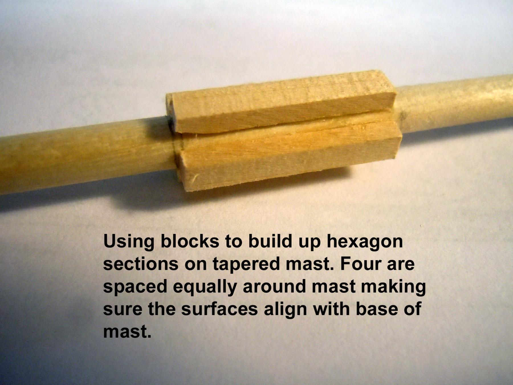
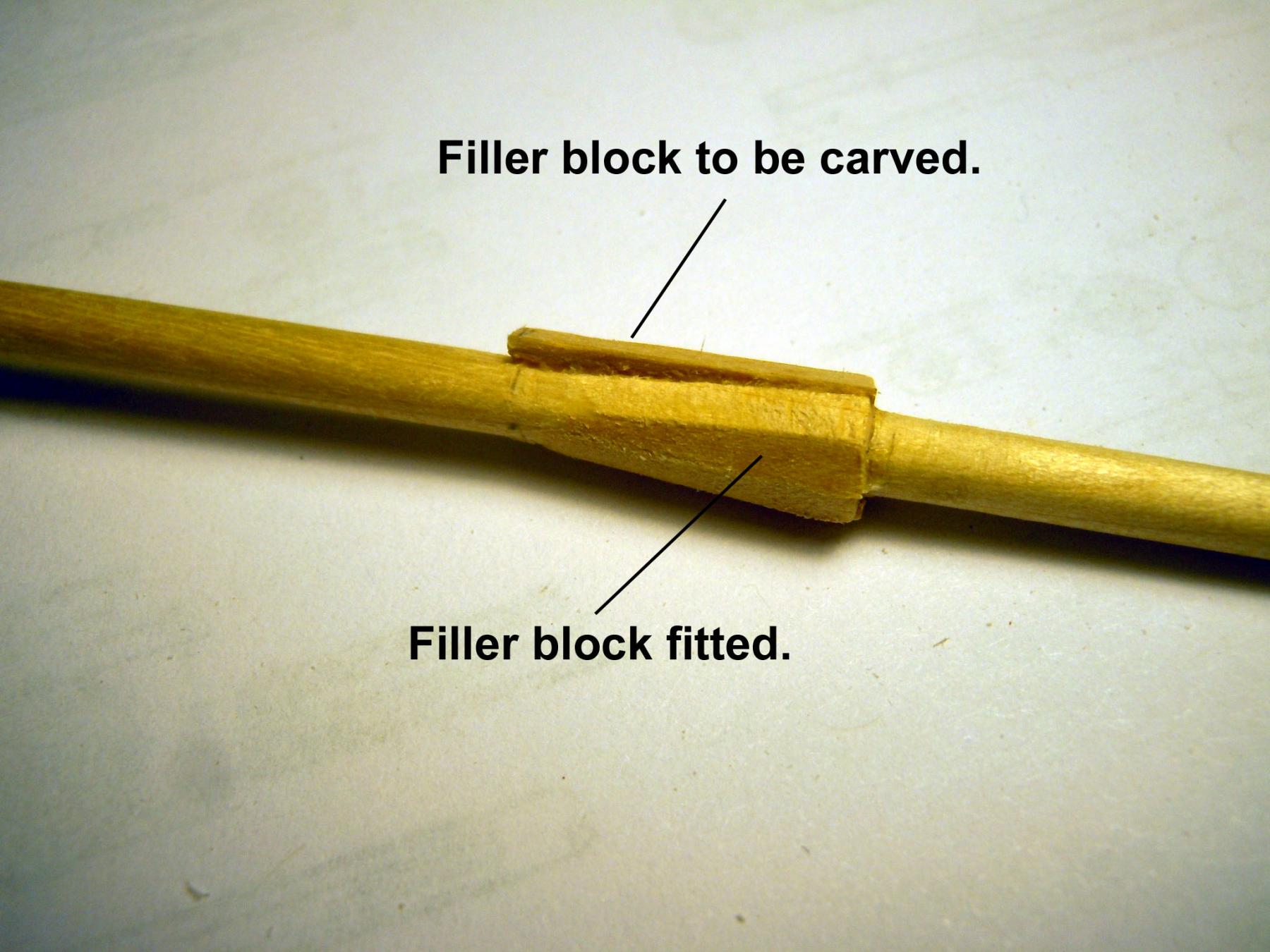
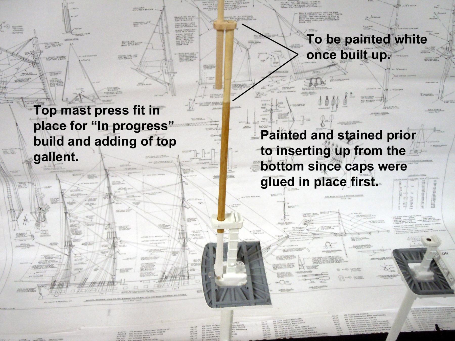
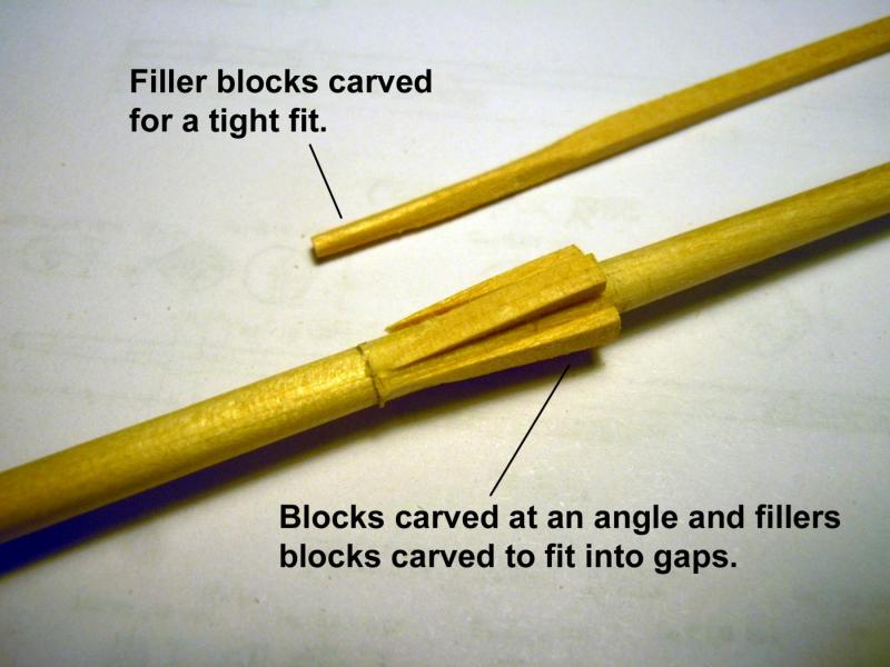
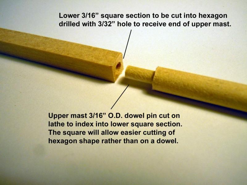
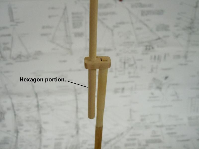
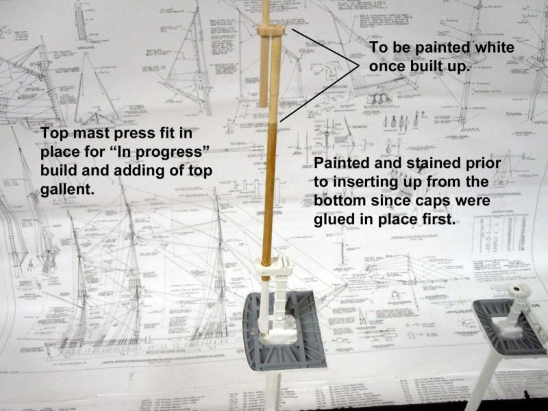
My son who I am building this ship for is coming to visit with our twin 5 month old grandsons this Saturday; so I have decided to build up the main mast so they can get a feel for the overall size it will be. I had glued the caps in place on the masts which I probably should have not done, so a lesson learned. However, the top masts can be inserted up through the bottom of the fighting top and pressed into place. I could not find on the plans the dimensions for the lower square or diameters needed for the top masts or gallant masts for the dowels to start with. Taking dimensions off the plans did not make sense. I have learned over the years in doing my own plans that when reproduced as much as 5% shrinkage can occur which is why I provide on my plans a 1 inch reference square so the printing/copying machines can be adjusted for an accurate reproduction. So I measured the holes in the fighting top and cap that the top mast was to index into and through to get the starting dimensions and the dowel size needed. I started with the top mast and carved the hexagon once the 7/16" dowel (this size was not in the kit so purchased) was cut to length and taper shaped using both small plane and scraping. While cutting the hexagon I realized that there was an easier way by starting with a square pinned into the dowel. I used this idea for the top gallant and it work much easier and more accurate than carving the dowel directly. The joint will be painted over with the white paint. Here is an "in progress" sequence showing the above. Now back to the main mast.
-
Jon, yes I realized that I should not have glued them either while I was building the tops. If I cannot feed the second step up through the lower holes I will cut and peg the caps. Another lesson learned and warning for others. The half bands and square bands are brass strips explained earlier in this build if you look back.
-
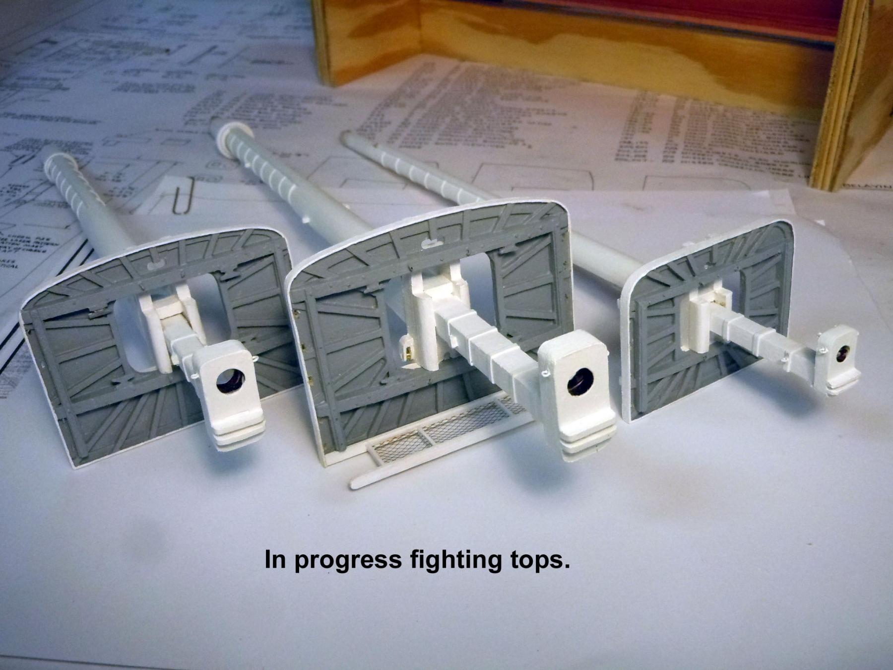
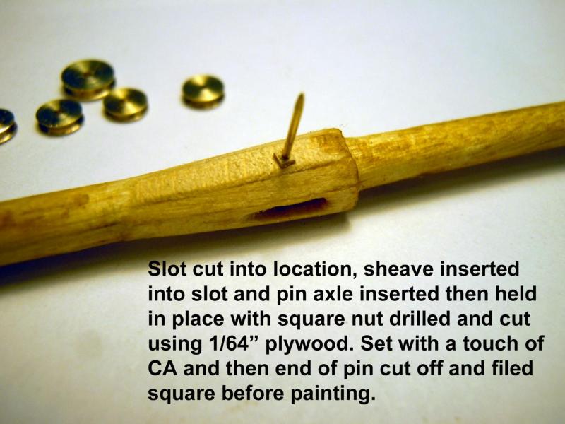
Jon, the turtle finally arrived! Thanks! Here are some pictures of the rivets you had a question on earlier. Then there were three.... I still need to add the guard rails and thumb sheaves to the fore mast and mizzen mast tops. Then onto the deadeyes.

-
Darrel, I think you need a 0 after the decimal point.
- 648 replies
-
- 3
-

-
- niagara
- model shipways
- (and 1 more)
-
Jon, thanks they look great and show that I am headed in the right direction. Sometimes it is fun being a detective trying to sort out what the plans and instructions have left out.
-
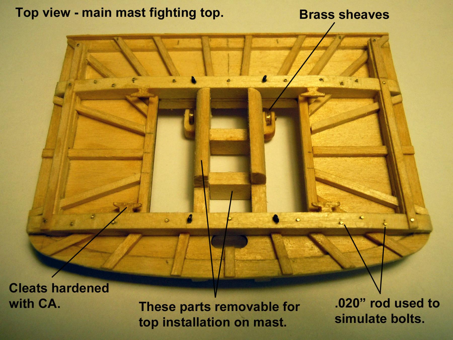
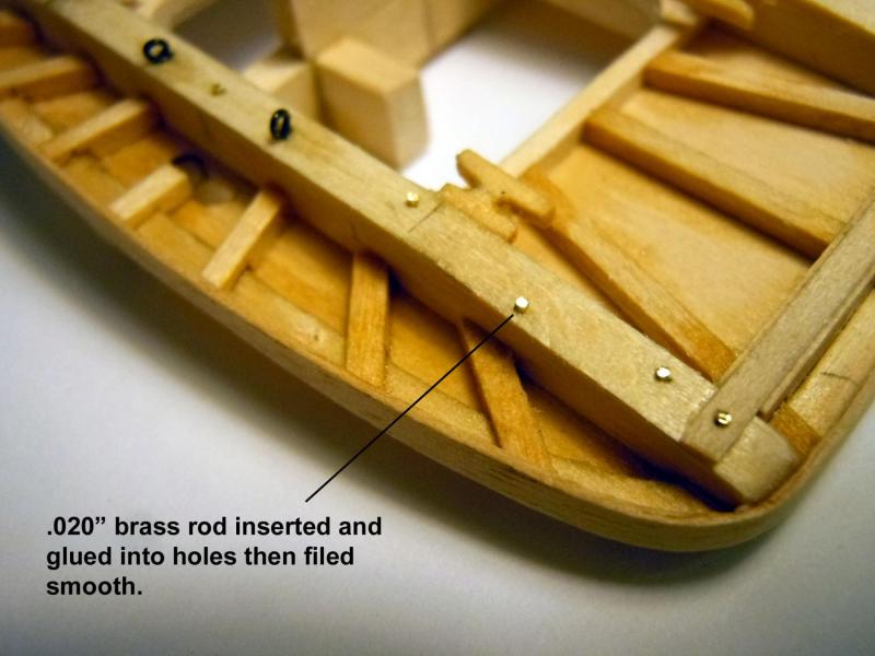
Jon, they are .020" rod dipped in CA and inserted into drilled holes then cut off and the tops filed square. Nothing in the mail today; that turtle must have stopped off for a cold one.
-
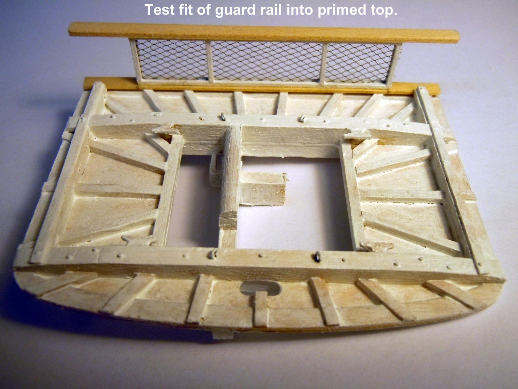
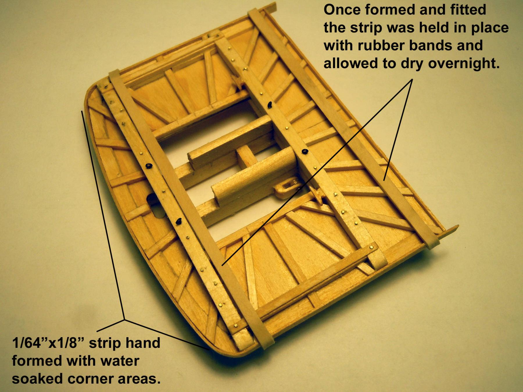
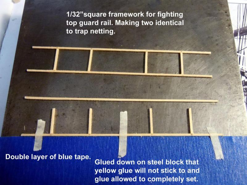
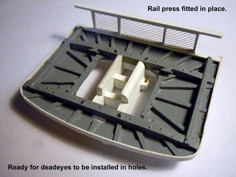
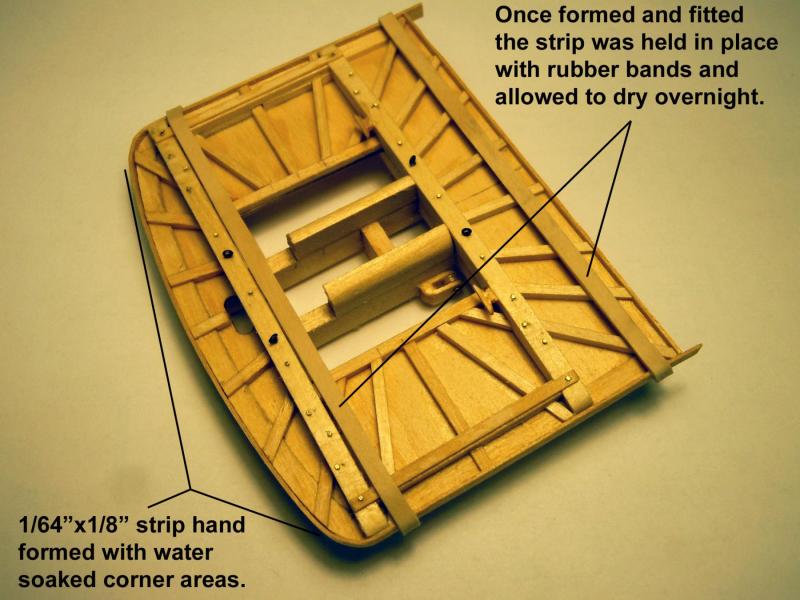
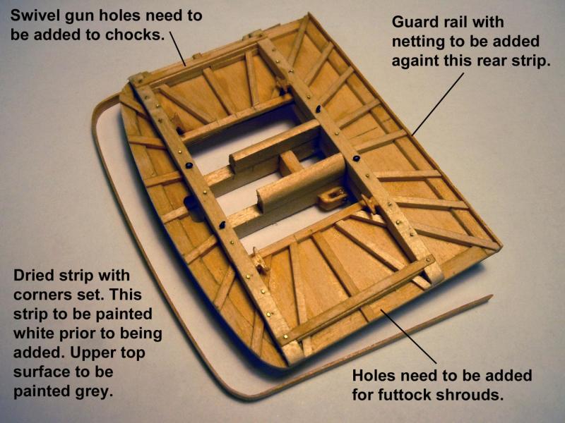
Jon, I may be ahead of the US Mail. I moved on to the guard rail using 1/32" square stock as framing material to trap the netting material. First I made one then duplicated a second one. They were assembled on the steel block that the yellow glue would not stick too and once glue was set careful separation was done with the tip of an Xacto blade. The netting was then sandwiched between the two frames that were glued together and excess netting and framing trimmed away. The caps were added and trimmed. Here is a test fit into the primed top. Also the inside radii were added to the top which were not noted on the plans. Here is the finished top ready for deadeyes and a pattern to build the next two. I still need to find the locations for the swivel guns and images of the guns themselves. Perhaps once the deadeyes are in place the locations may be more obvious. On to building the other two and add deadeyes in the meantime.

-
Jon, not in the mail today, hopefully tomorrow. I may beat the US Mail and get the first top completed.
-
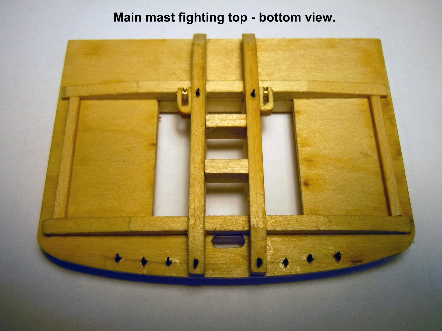
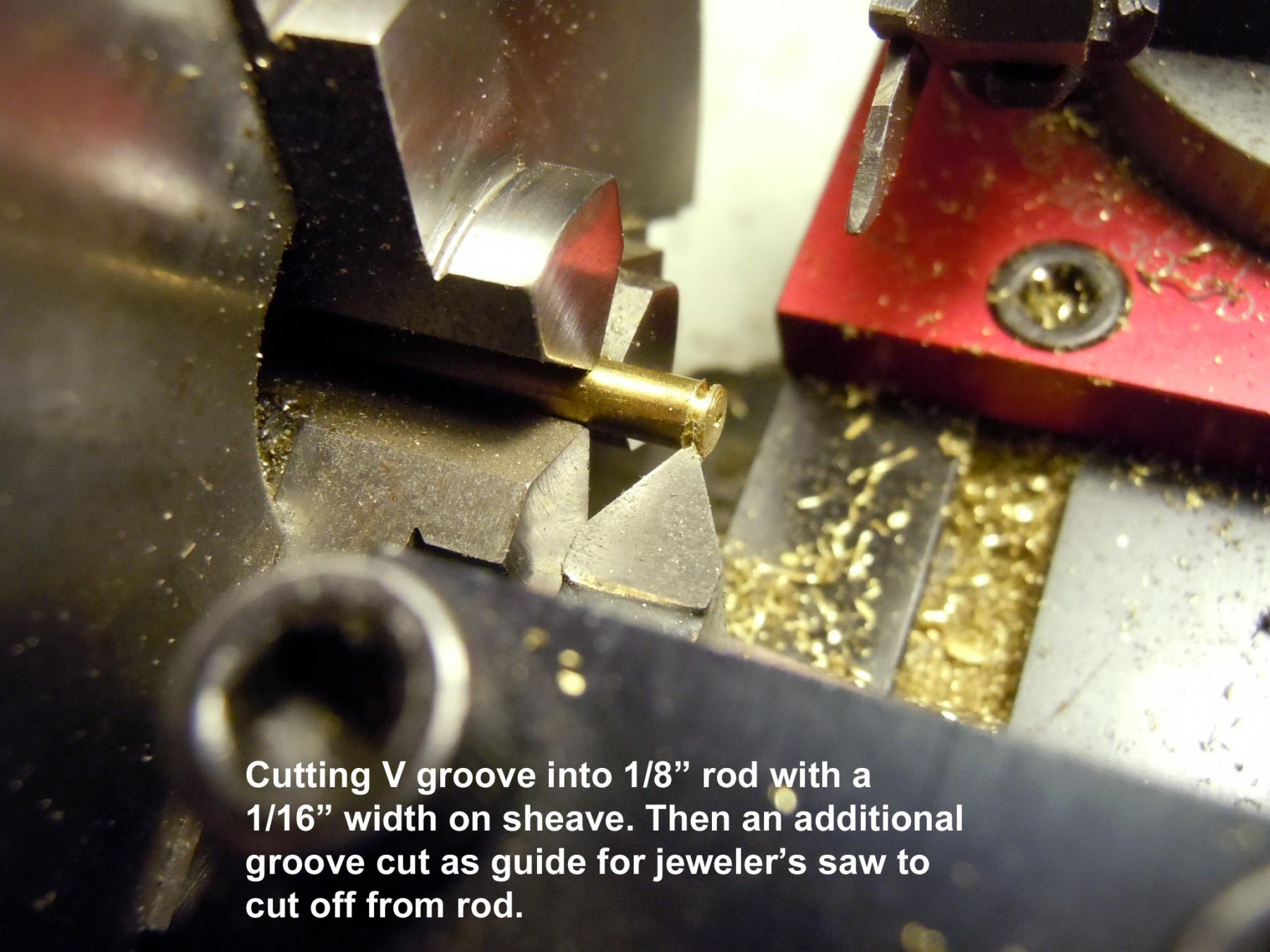
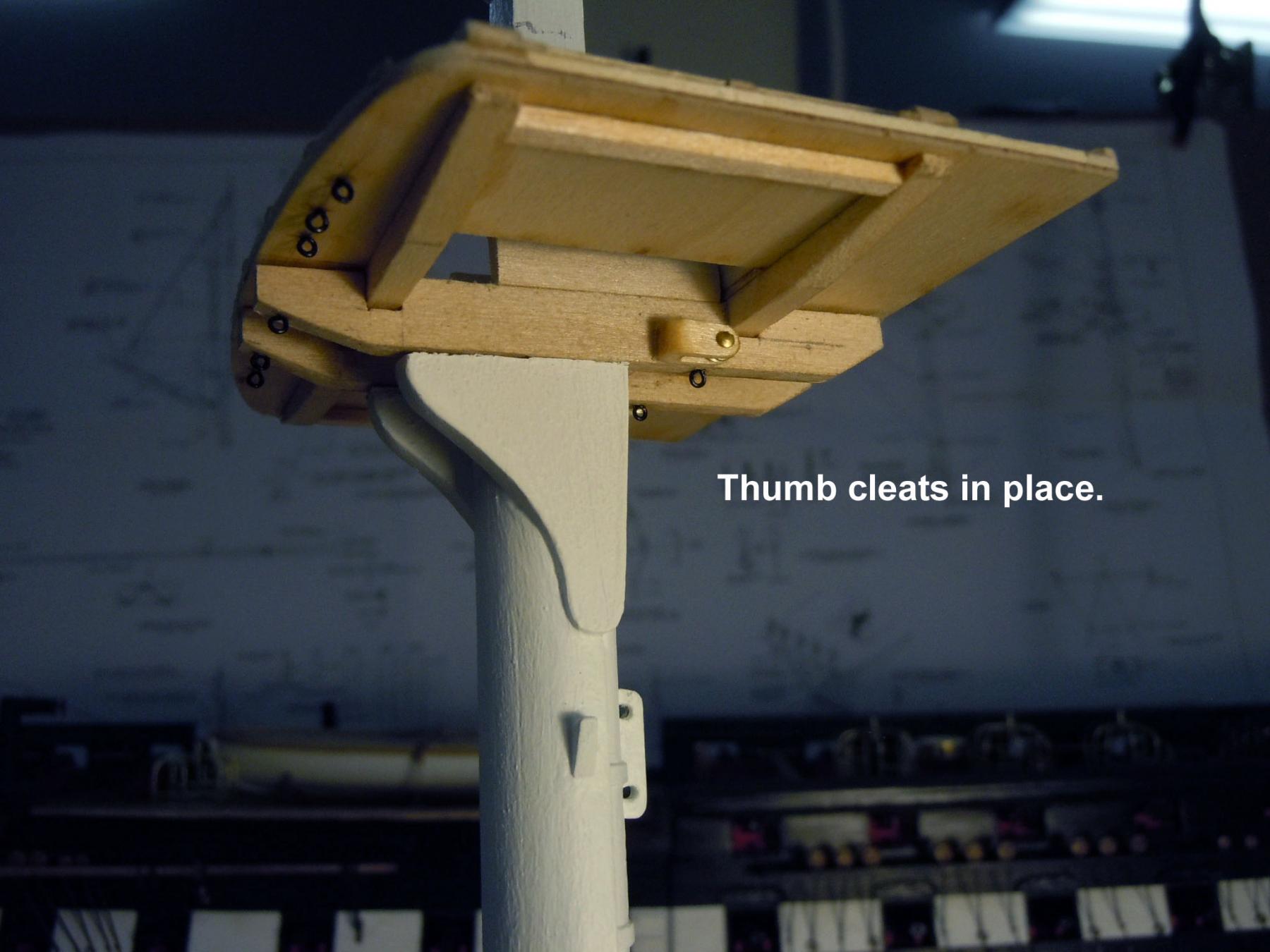
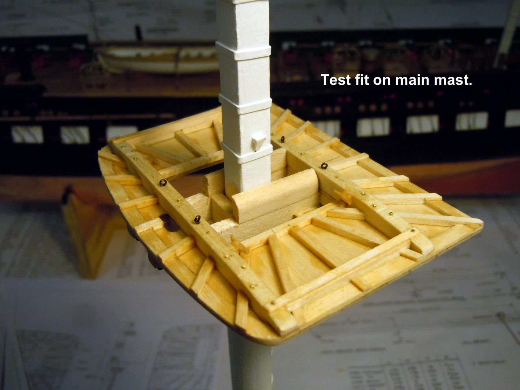
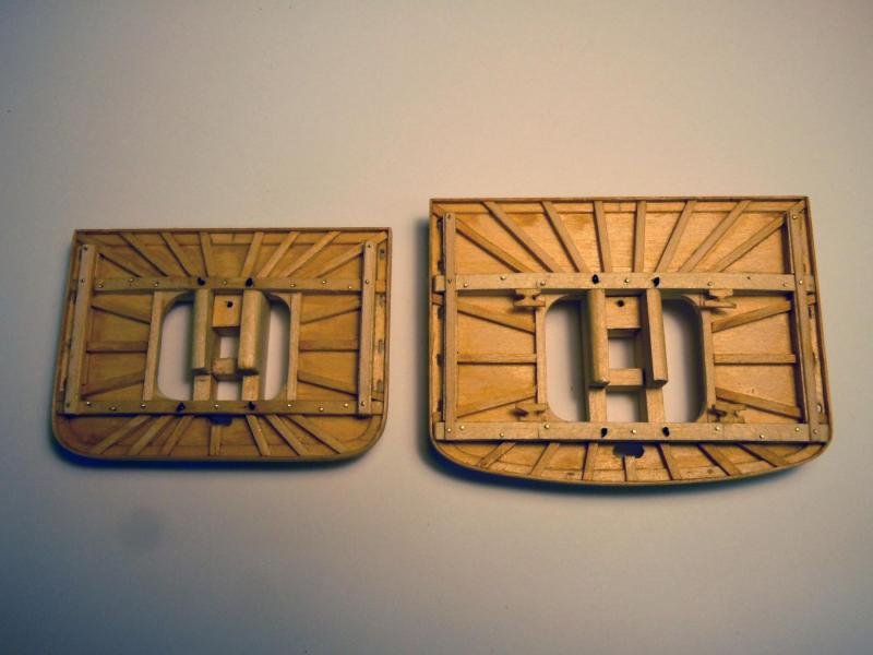
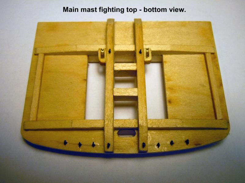
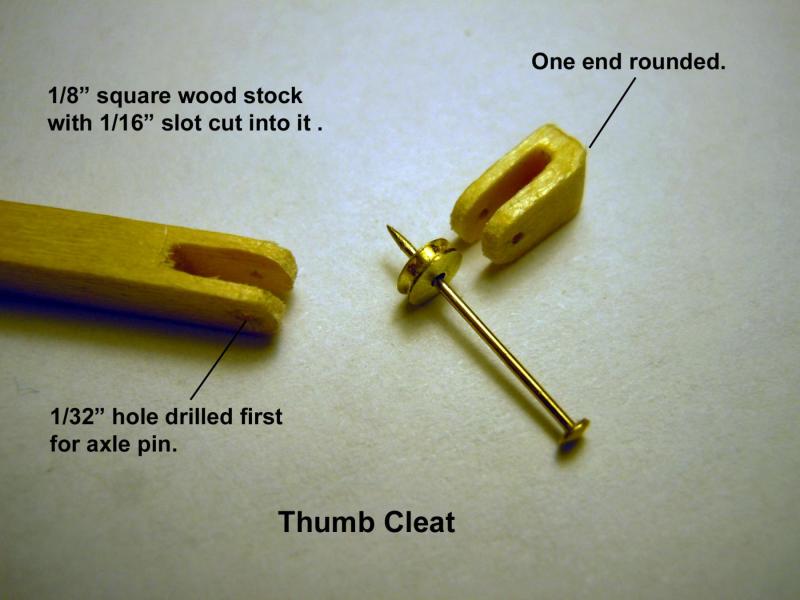
Well back to working with wood and decided to build the main mast fighting top first as a guide for the others. These are almost a model in themselves. The plans and instructions are real sketchy on these and lack details discovered while looking at photos and a naval yard plan. I am still in the process of finding eyebolt locations on the bottom. Here is an "in progress" building sequence that I hope will benefit some who will follow. First I discovered during the build that since I already built the masts with rings and mast caps that a trestle and cross block would have to not glued in place to allow assembly installation on the mast. Lesson learned and advice to others: hold off on adding rings and caps until fighting tops are installed. Here is a sequence of making the thumb cleat with sheave. Here is a test fit. After taking the pictures I discovered that the swivel gun chocks needed to be extended to the rear corners. The extended ones are in the first picture. I will need to add the mounting holes for the swivel guns. If anyone has images of what these guns should look like I would greatly appreciate an image so I could add them; these would be a nice little detail. Back to being a detective and add some eyebolts to the bottom and build the guard rail. Once I have this one built I will use it as a guide for the other two.


-
Steve, I usually order from: http://www.specialshapes.com/ but plan ahead for your needs because they have a $20 minimum order. As for the next subject ... nothing firm at this point but thinking of perhaps a scratch build.
-
Steve, here you go, hopefully it works. I started with the small boats to get the feel of things and doing boat work. Enjoy! Any questions just ask. http://modelshipworld.com/index.php/topic/10038-us-brig-niagara-by-xken-finished-model-shipways-scale-164/page-1