xken
-
Posts
841 -
Joined
-
Last visited
Content Type
Profiles
Forums
Gallery
Events
Everything posted by xken
-
 Nils, Thank you! I also enjoyed looking at your builds and brass work as well. I see that you do a great deal of steel ships; here is a link to rivets that you may wish to evaluate for extra details on your builds. http://www.scalehardware.com/miniature-rivets-c-10 Keep up the great work you are doing and I encourage other builders to look at and enjoy Nils builds. Thanks again!
 -
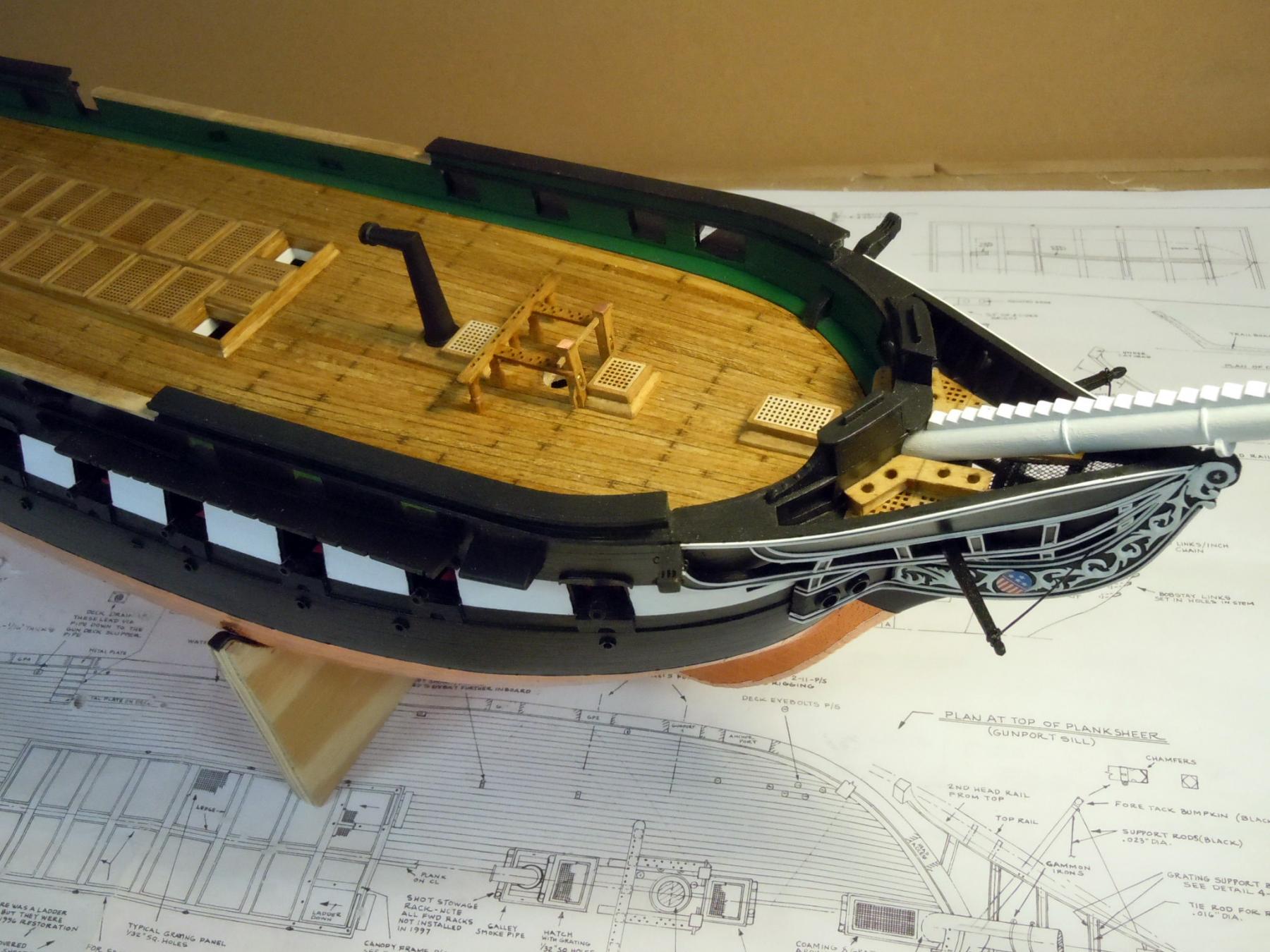
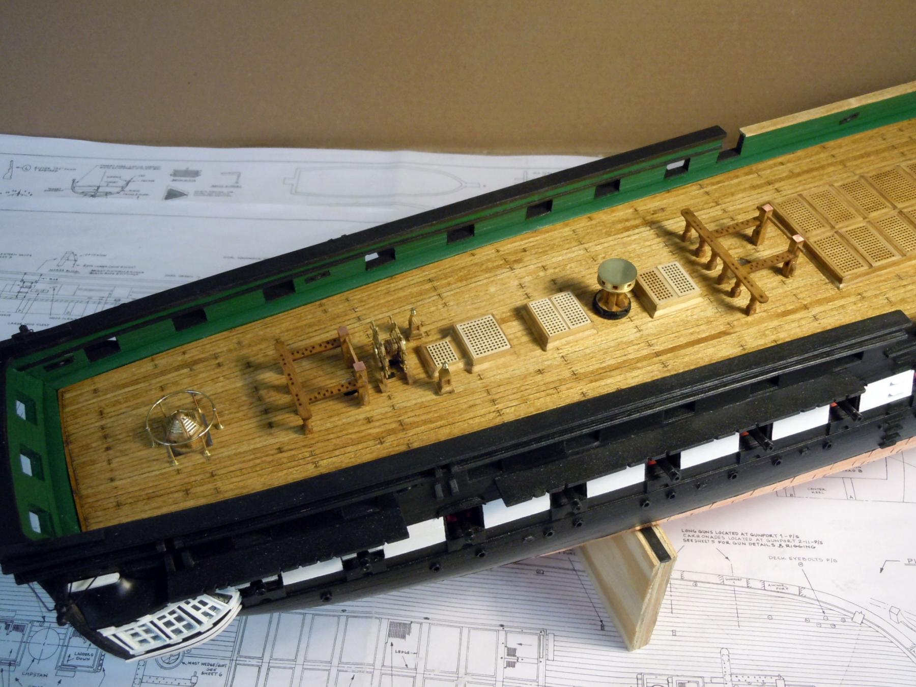
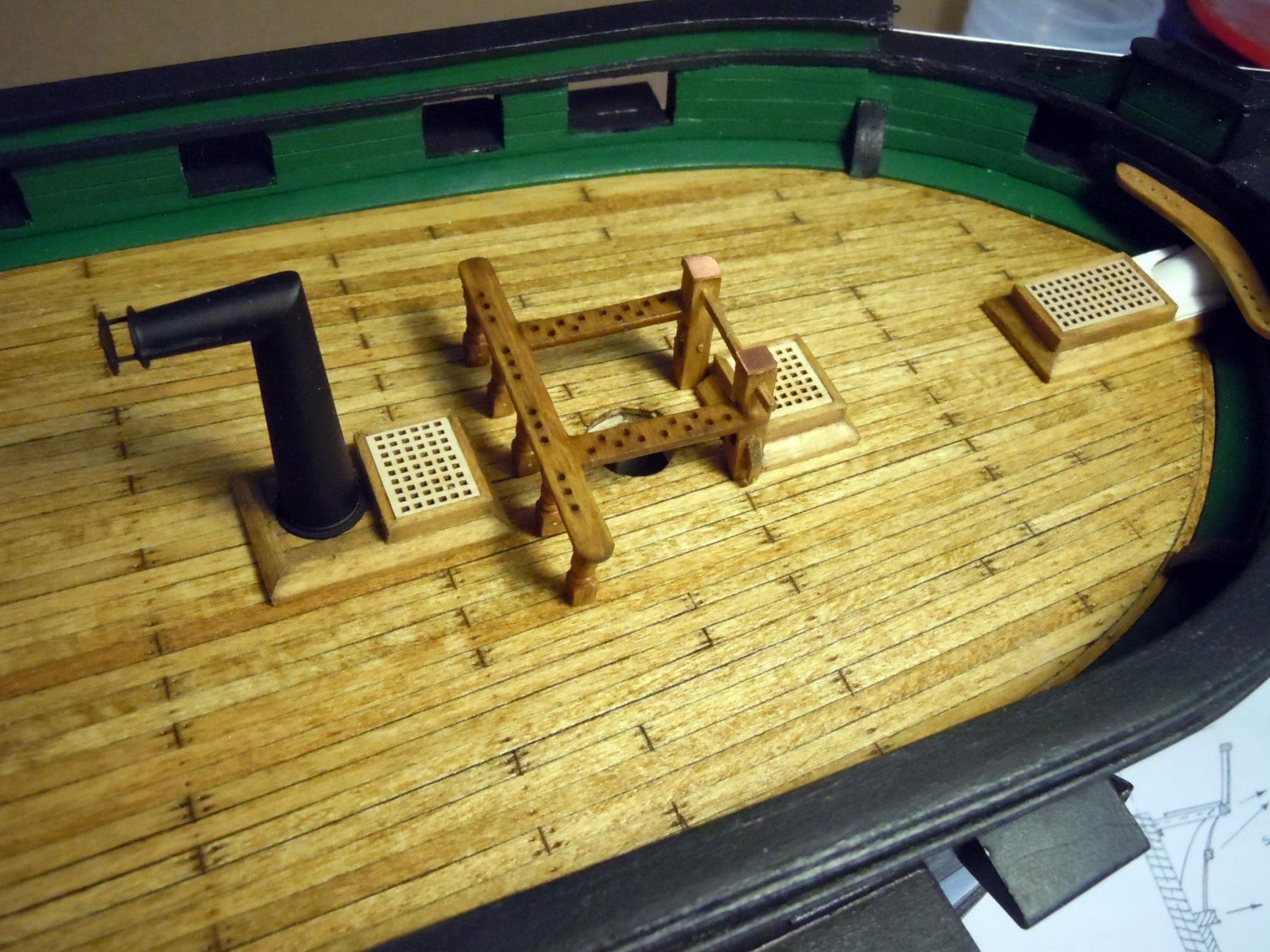
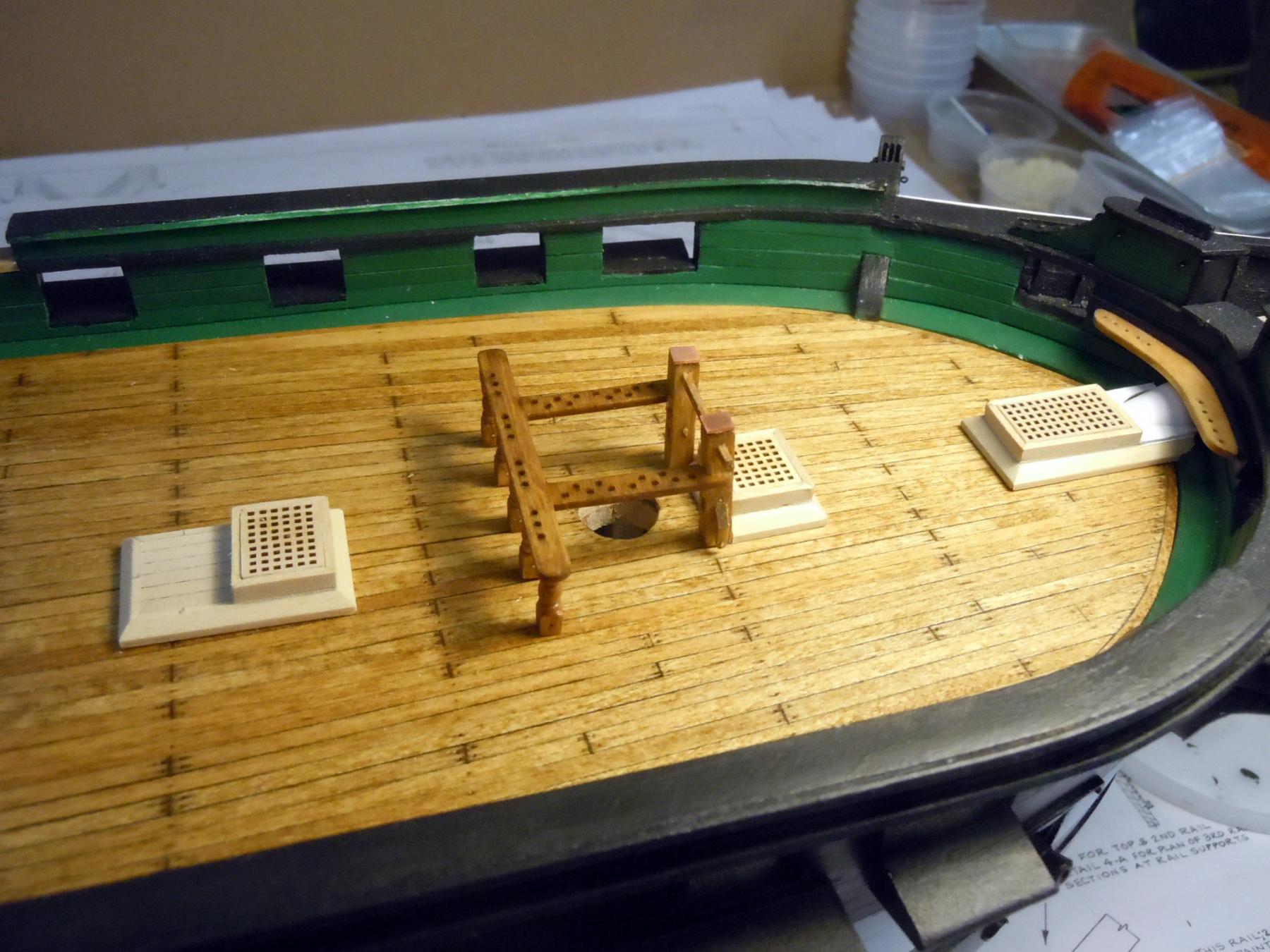
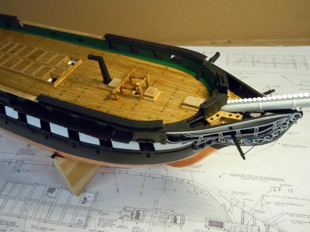
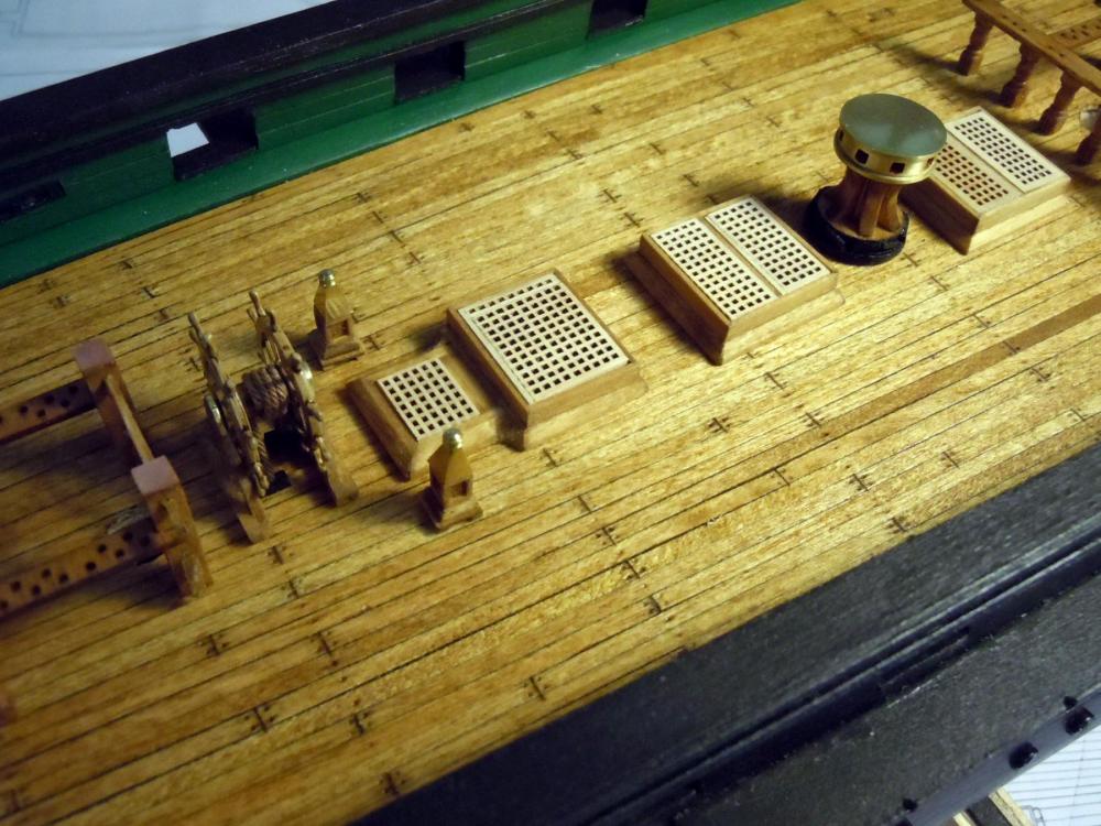
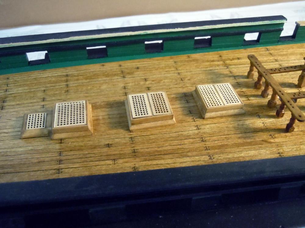
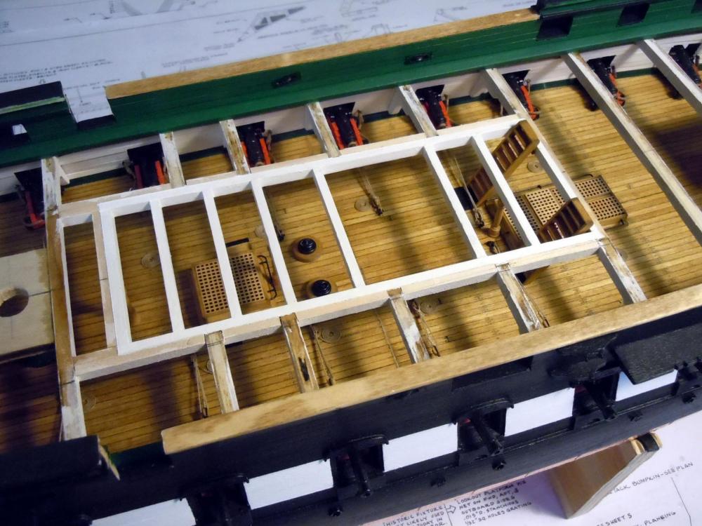
Thank you both for your kind compliments; and yes having the right tools make a great difference. This is why I really like the precision of the Sherline lathe cutting these tiny details. I finally glued the spar decking in place using the cross beams through the gunports and wedges for tight fitting and allowed the assembly to set overnight. I then located the deck structures with their locating pins and drilled needed holes into the deck. I will next address the various items to be attached to the ceiling walls using locating pins. Thus the deck structures will not be glued in place for now so that holes can be drilled without their interference. Here are pictures of the structures just set in place for now just to get a feel for how they will look. One detail I am trying to sort out is the 1/32" raised deck area shown on the plans, but is not seen on the photos of the restored ship. It is a deck doubler extending from the companionway aft of the main mast to the mizzen mast fife rail. Any advice or knowledge on this detail is welcomed on which would be correct for what period?


-
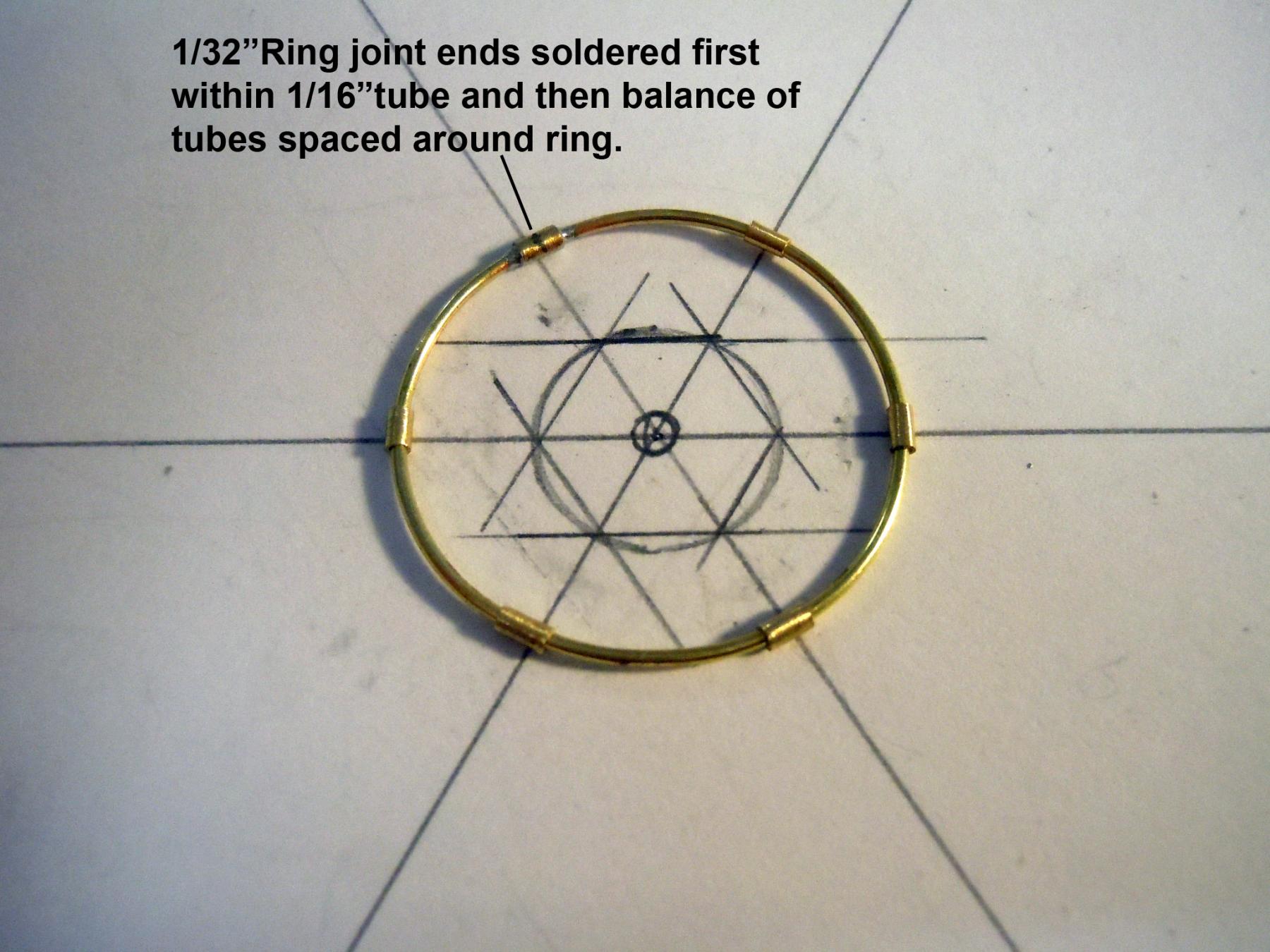
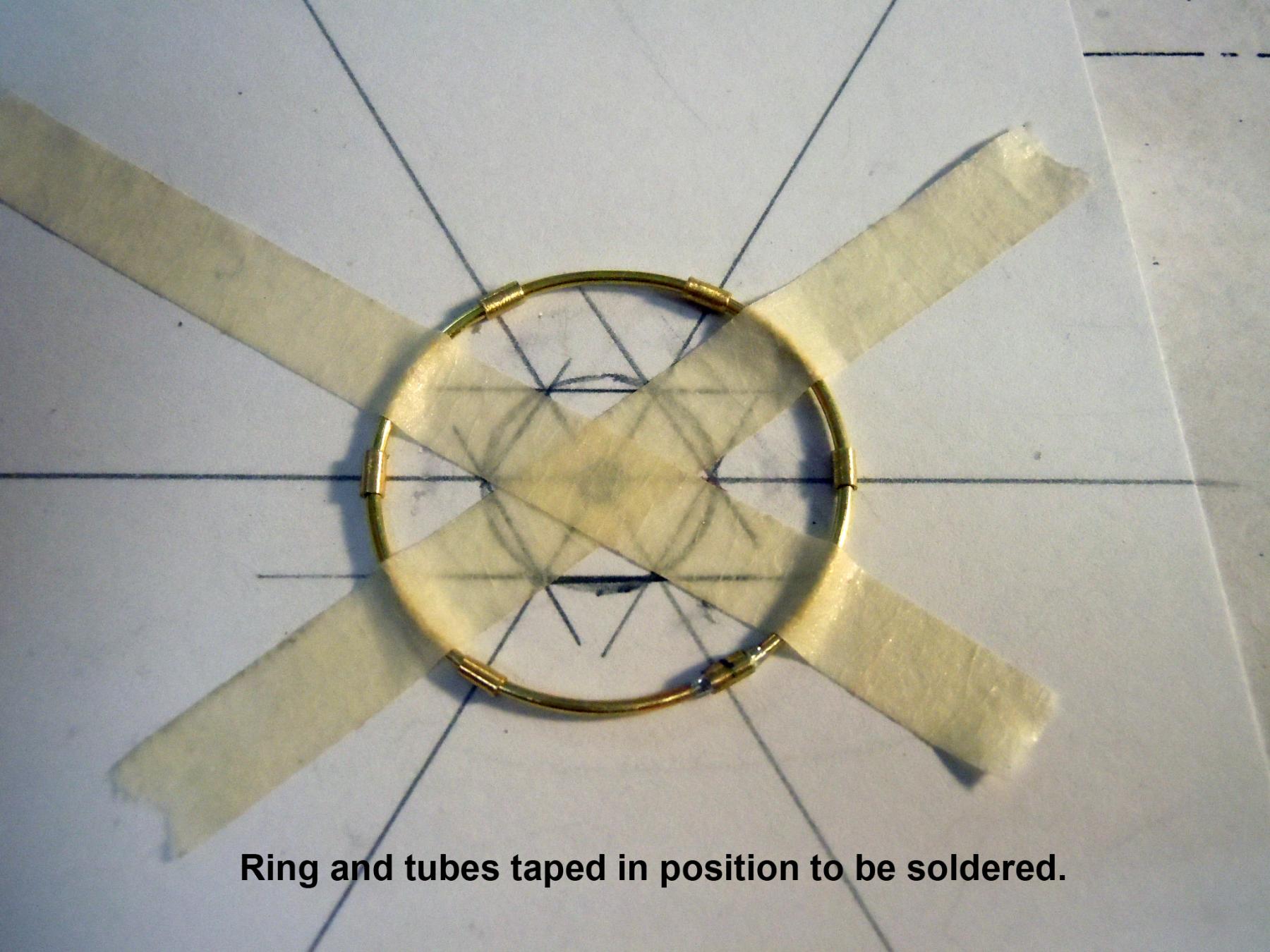
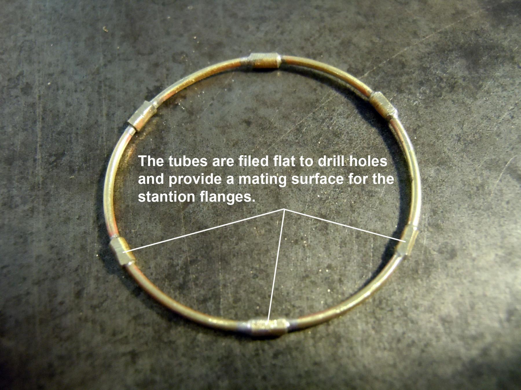
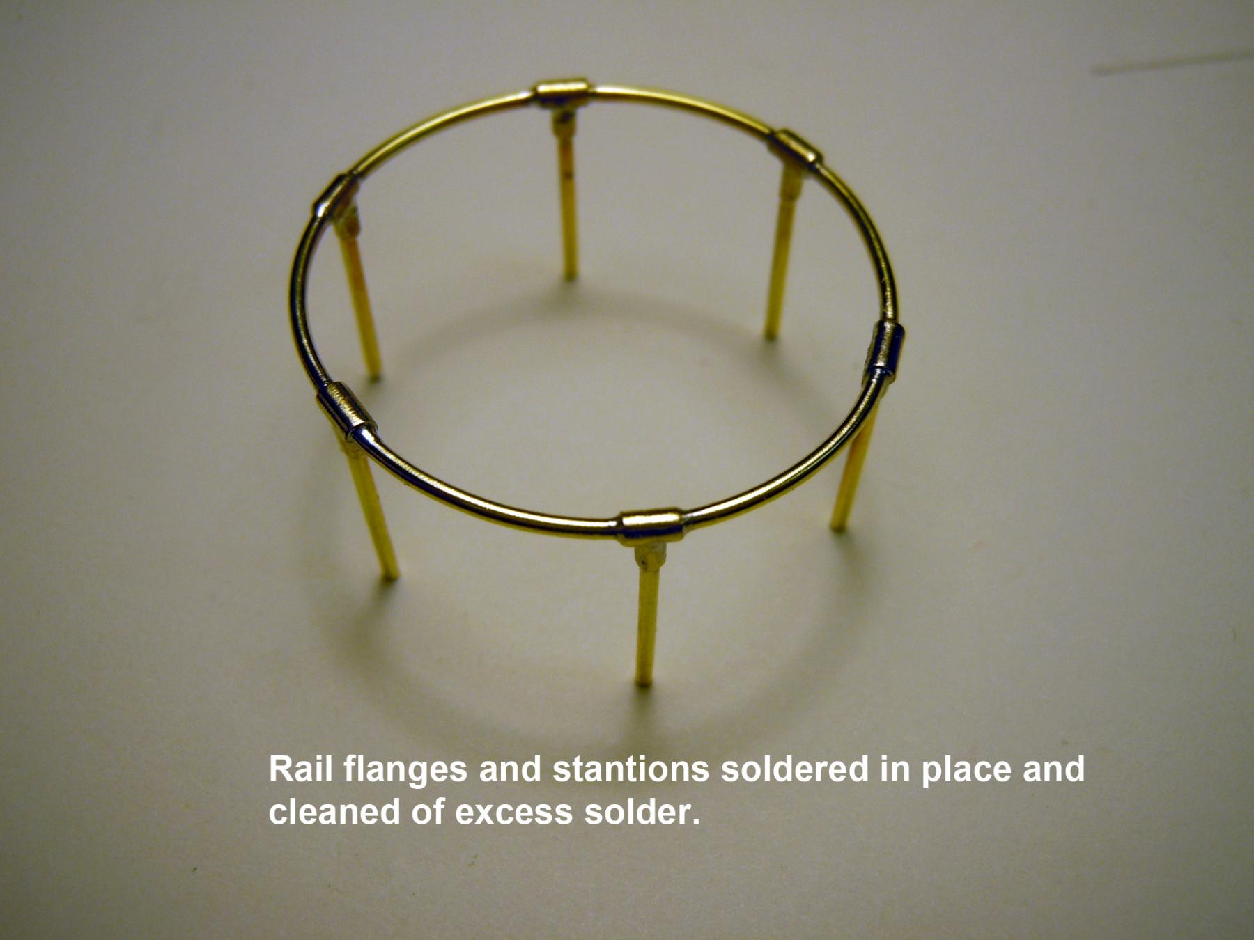
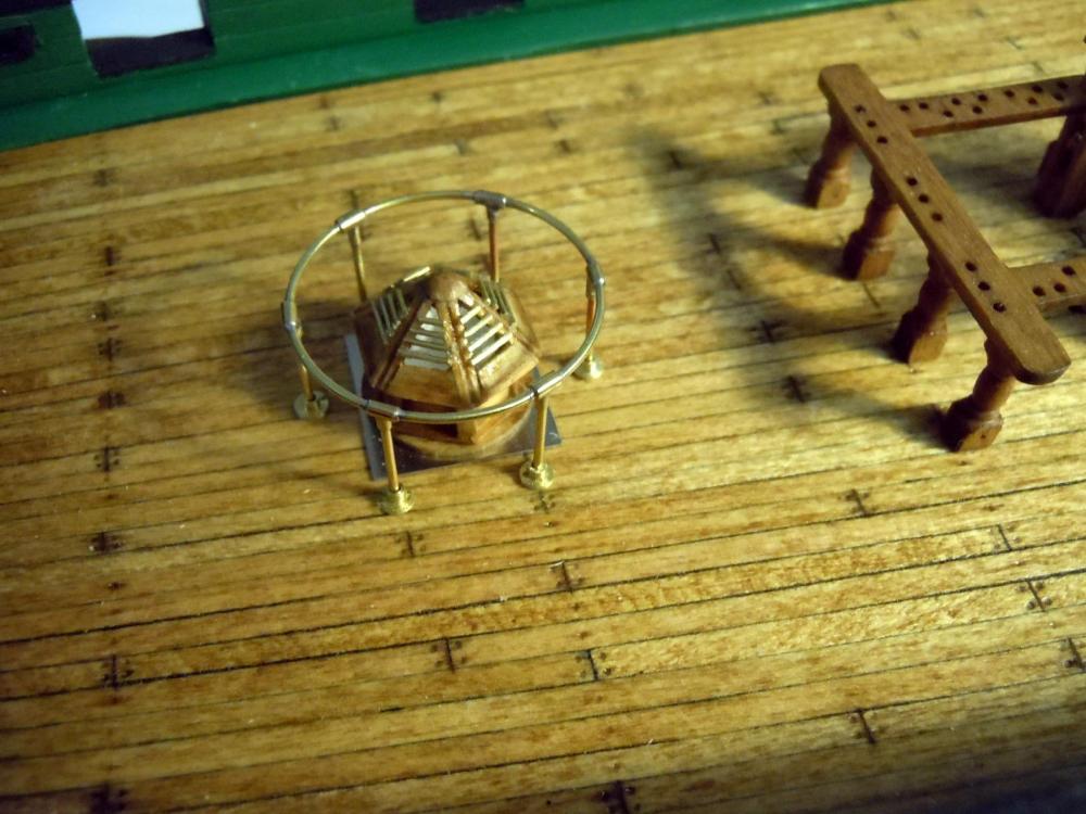
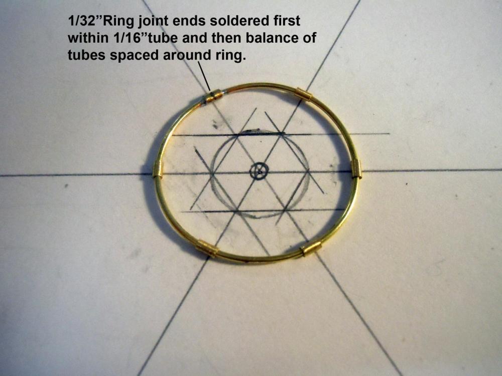
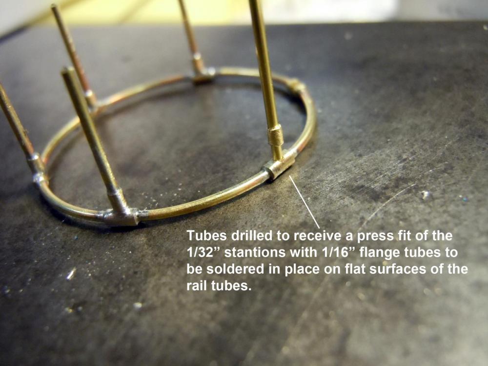
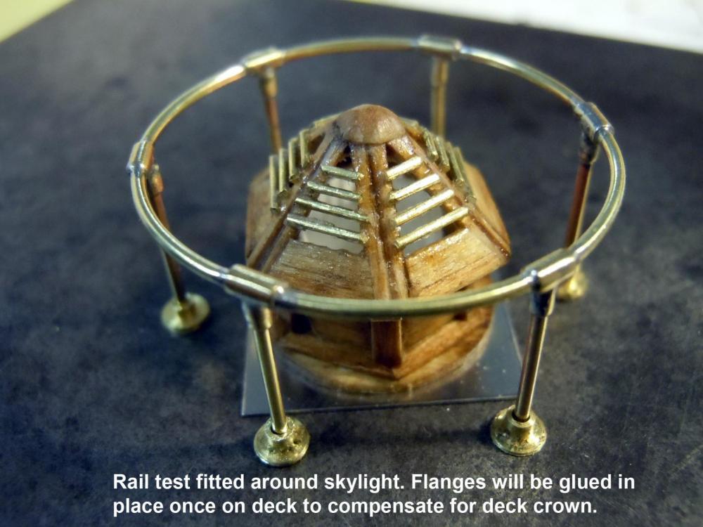
Happy Fourth of July to All! Back to ship pictures for skylight rail details. I formed a circle to size using 1/32" brass rod and then cut 3/32" long 1/16" tubes and fitted on the rail and fitted the circle ends within one tube and soldered. Then six 1/32" stanchions with mating flanges soldered in place. The deck flanges were cut and will be glued in place to conform to the deck crown once the deck is glued down to the hull. Here is a sequence of pictures. Pardon my misspelling of stanchions in photos. I decided to use a piece of stainless steel for the base plate; the painted brass one just did not look right. Now to add rails and cannon ball holders to hatch components and grates.


-
Joe, the wood was just a scrap piece off the basswood filler blocks for the bow, nothing special. Just used a brand new blade and a slicing action when cutting versus a straight push down of the blade. Thank you both for you compliments.
-
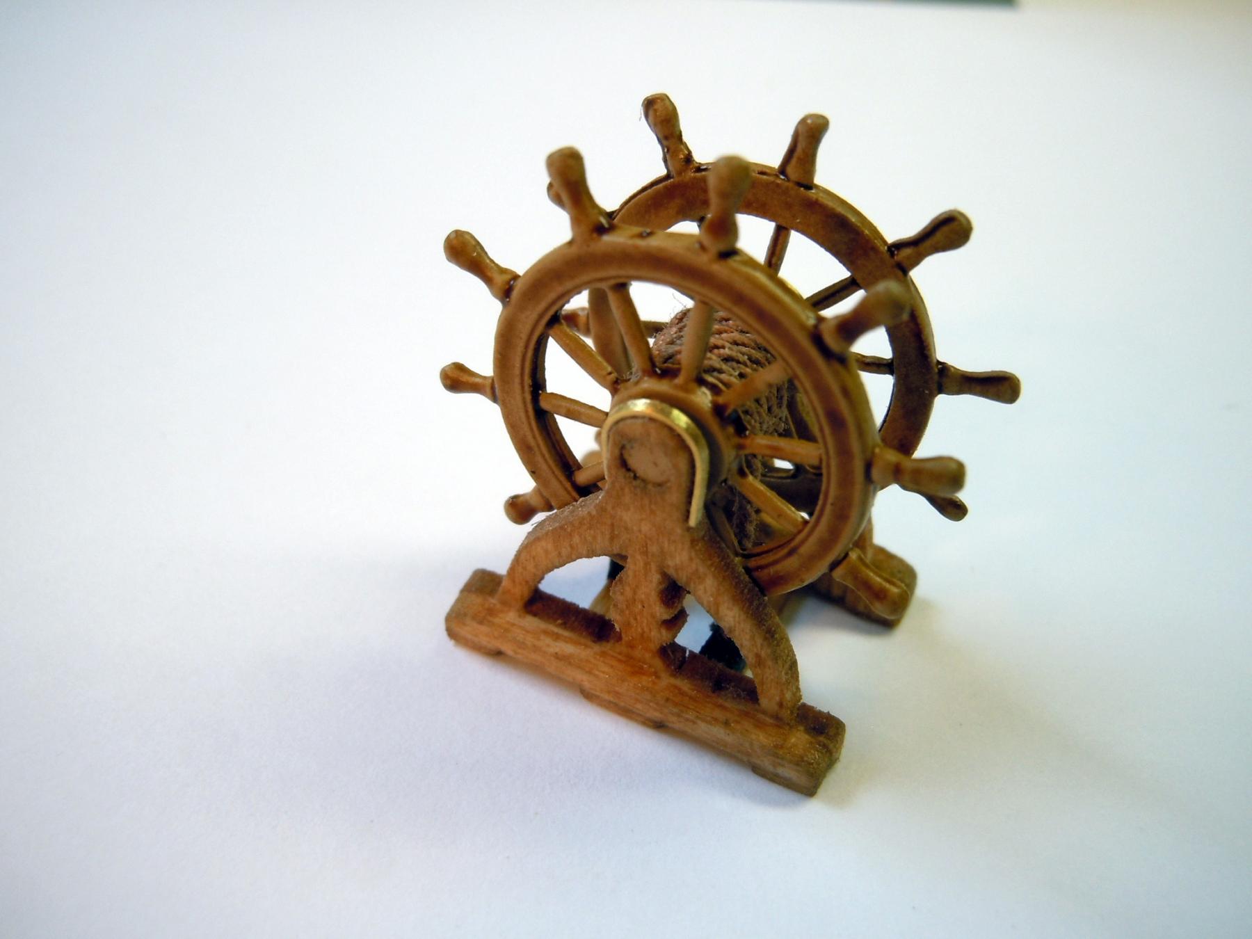
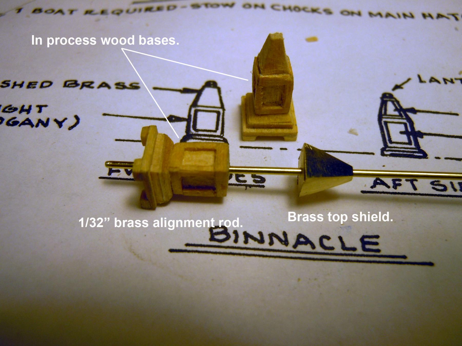
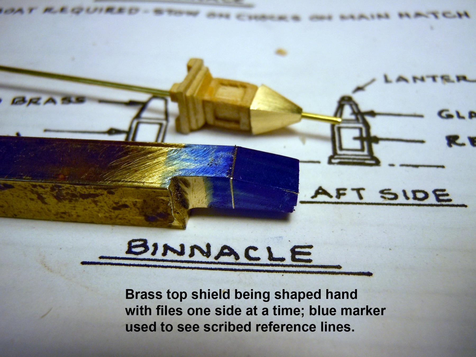
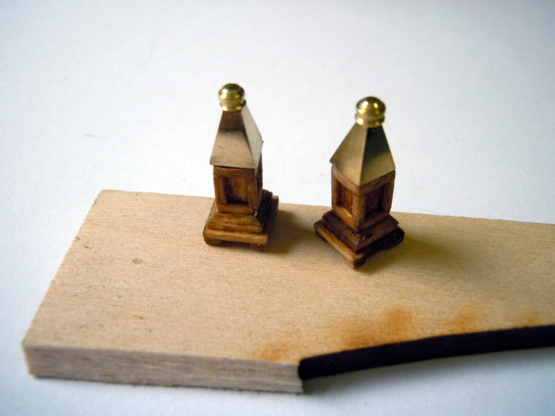
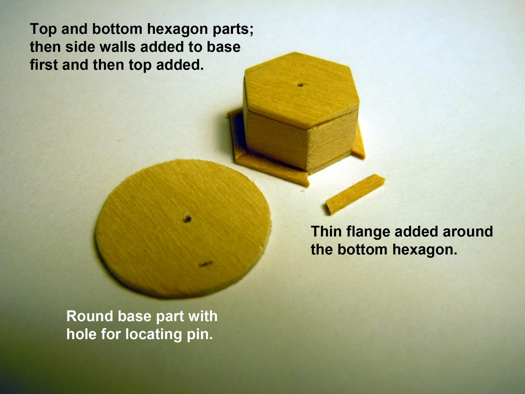
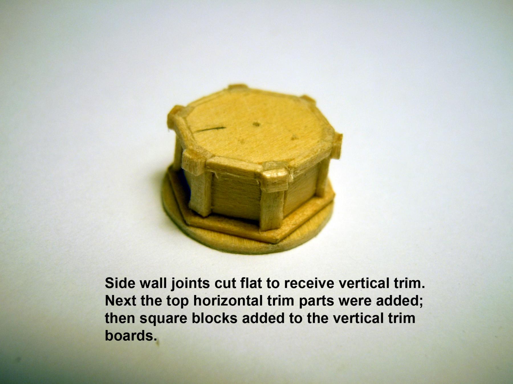
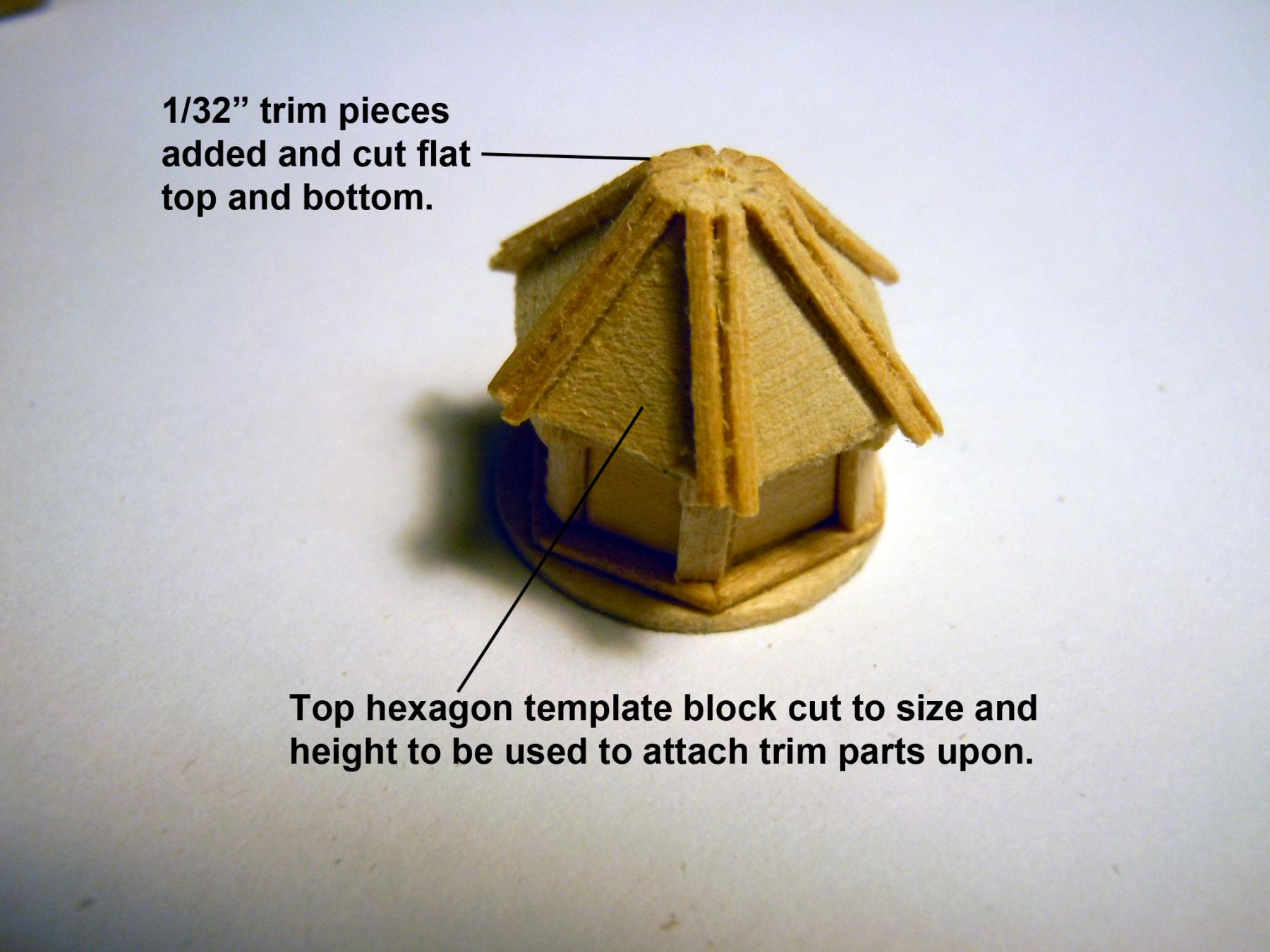
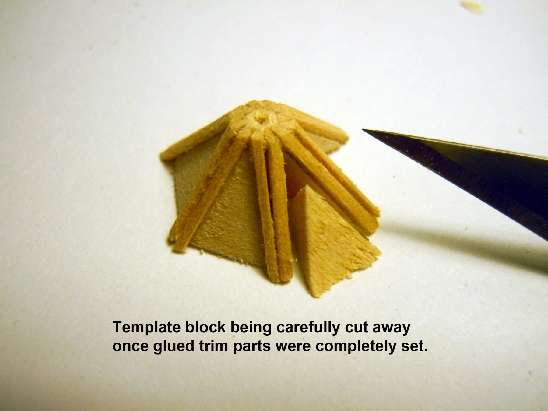
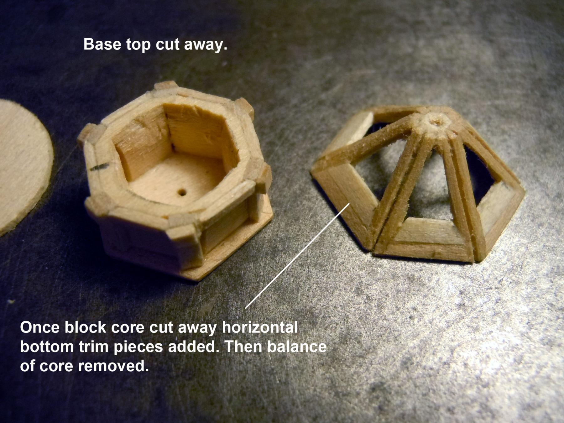
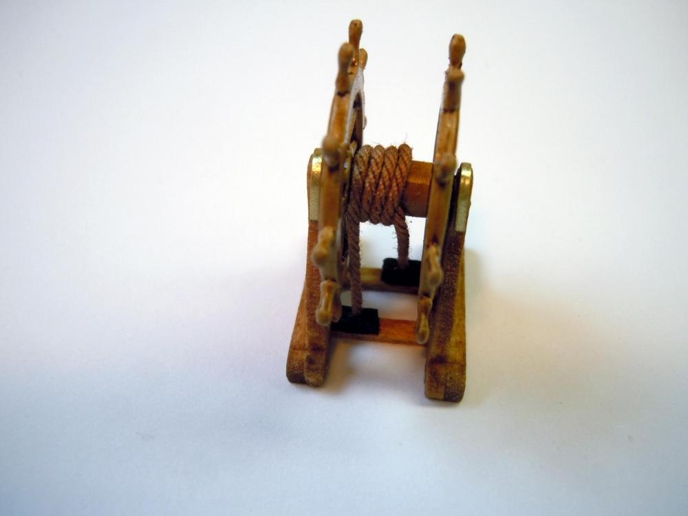
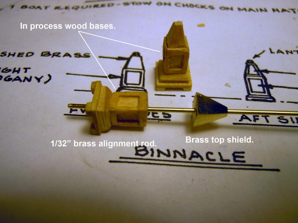
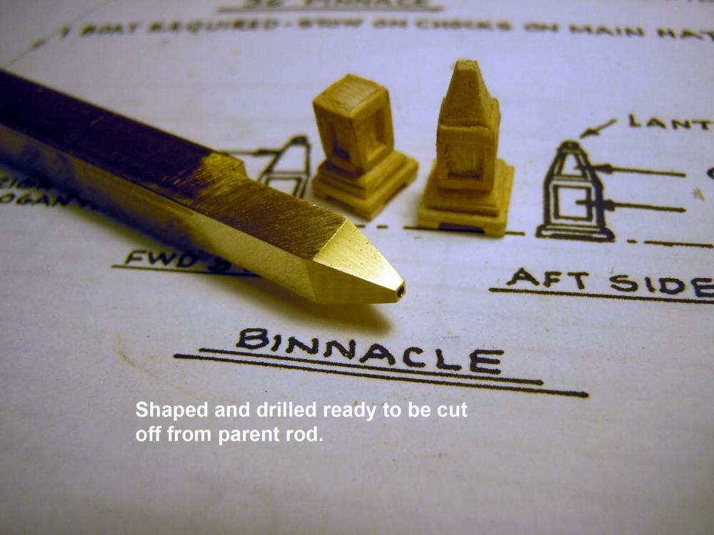
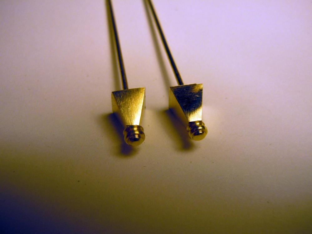
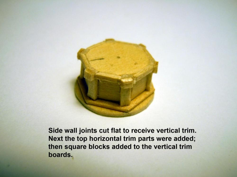
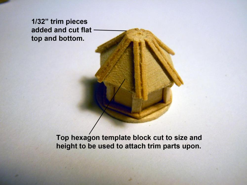
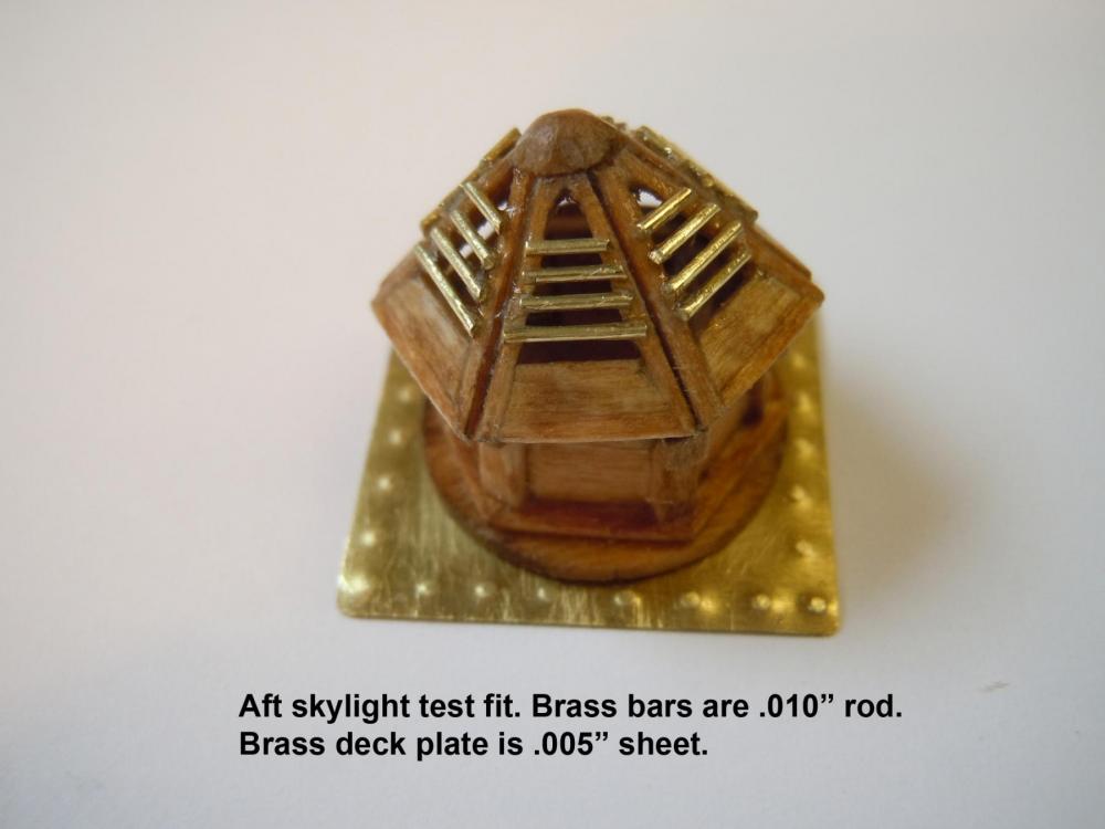
Have been working off and on with helping with the kids renovation project and babysitting the grandchildren to get them away from loud equipment. But in the meantime did some work on the deck structures and here are some progress photos of the steering wheel, binnacles and aft skylight. These are somewhat small items scratch built from wood with the exception of the cast steering wheel parts that were painted and stained. Here I used .035" rope around the axle and into the rope leads at the deck. Here is a sequence of the binnacle using a .032" rod for center alignment and indexing into deck. Here are the brass shrouds with a polished finish. Finished up ready for installation. Here is the aft skylight that required many angle cuts and a sacrificed core for the upper framing. This is the base unit. Here is the sacrificed wood core with framing being glued to it. This shows the cutting away of the core before the bottom framing is added. This shows the individual wood parts and before the brass bars were added to the upper cap. Here is a test fit and I think I will paint the inside of the lower base white, and the deck plate steel gray. Now back to work.


-
Don, the main tool is a Sherline lathe, tool bits, files, sanding sticks Ko
-
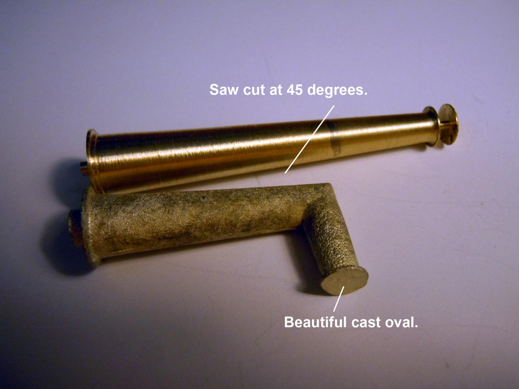
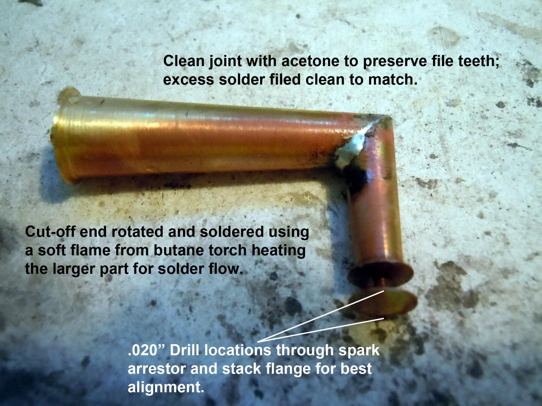
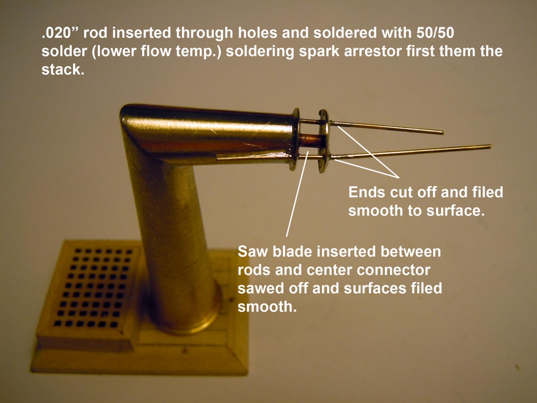
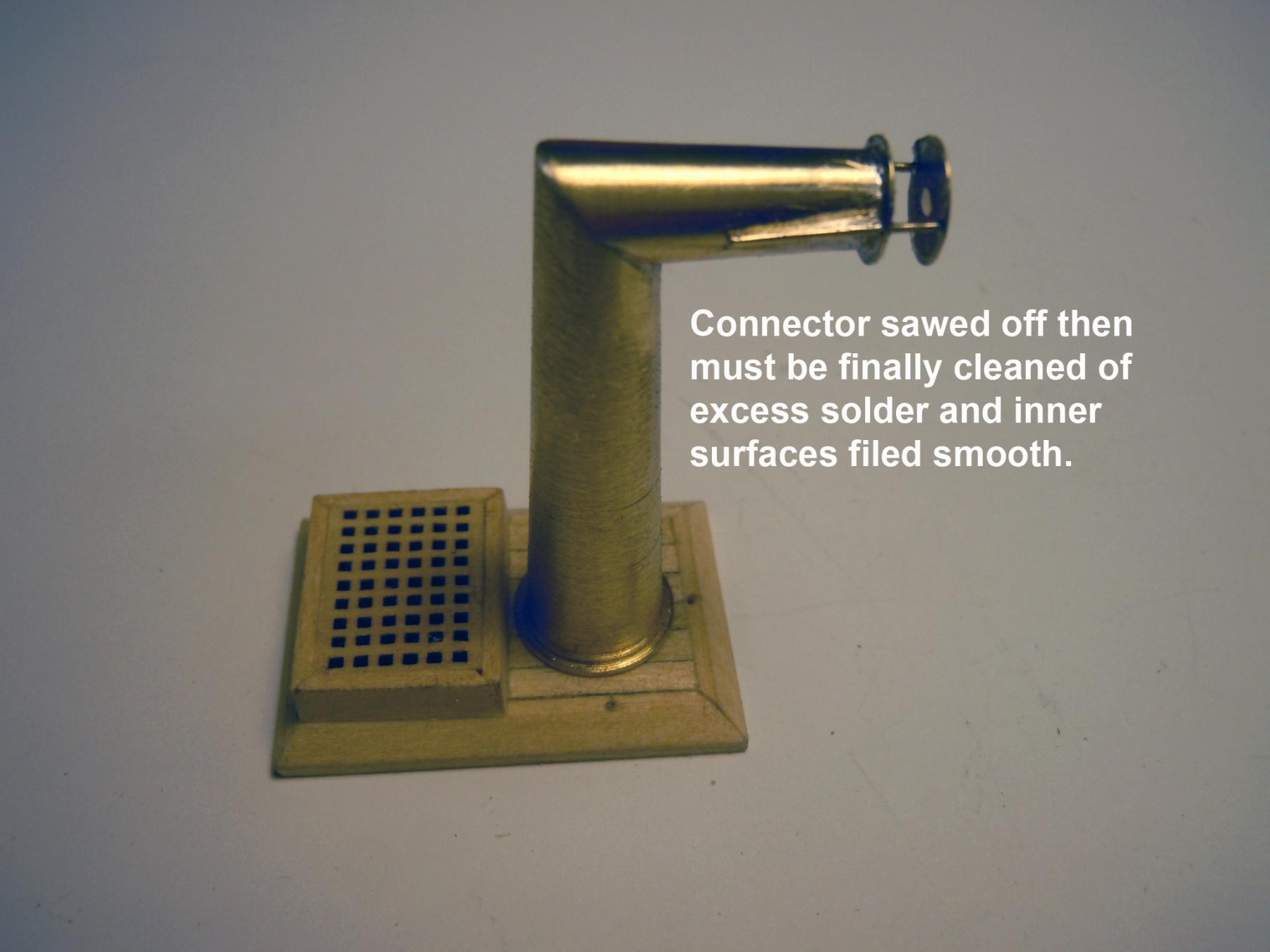
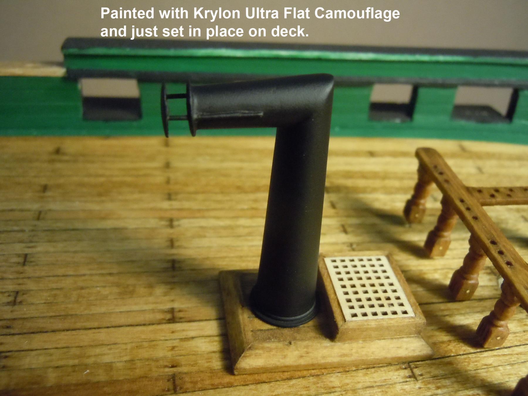
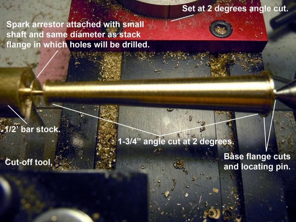
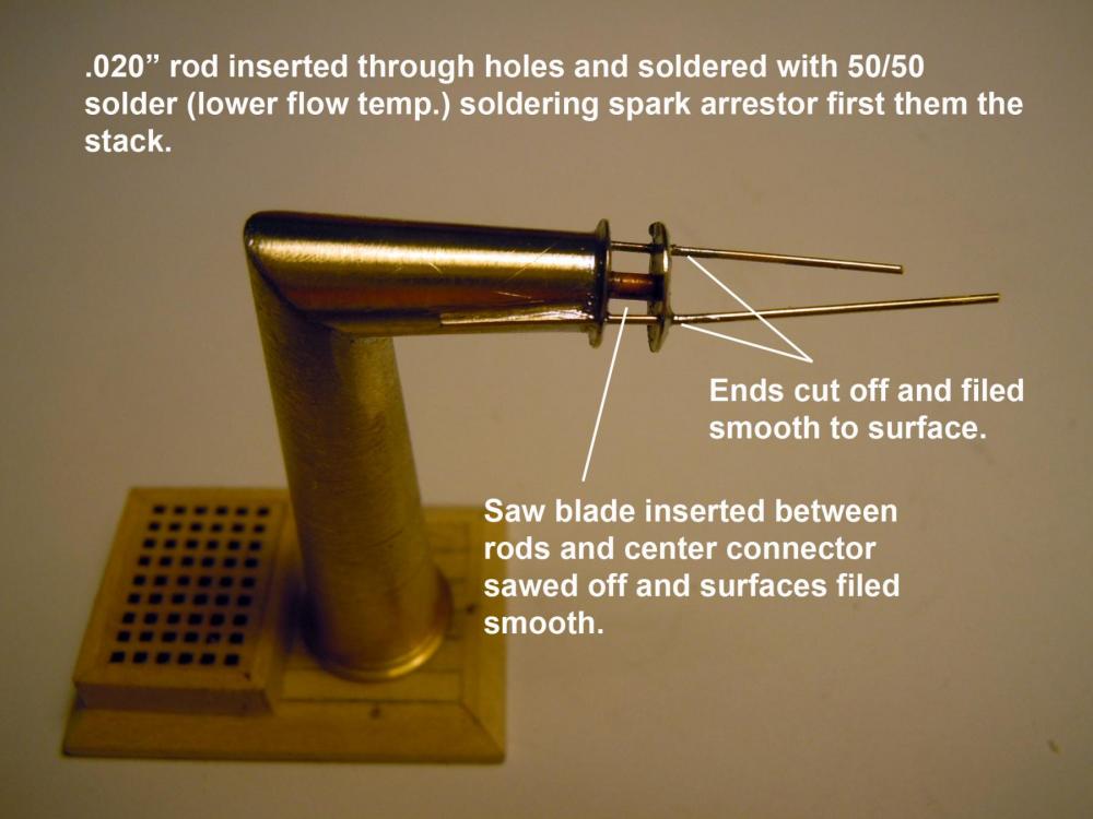
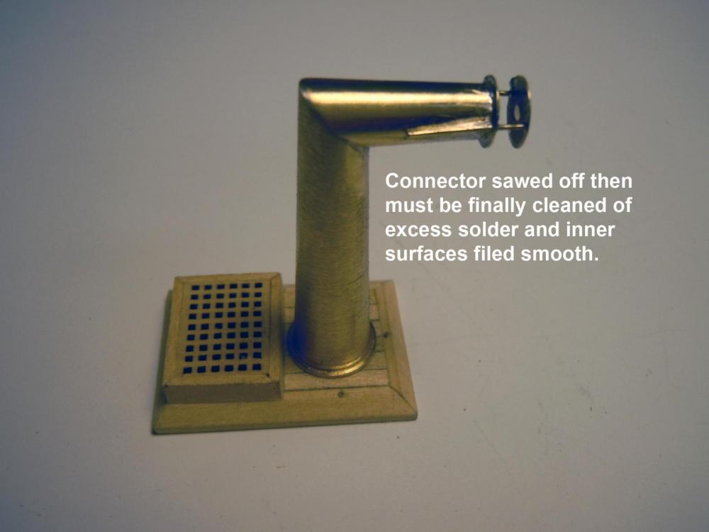
Jon here is an example why a lathe comes in handy. The kit smokestack was a POS casting with the mold being squeezed too much and formed an oval versus a round part aside from the rough porous surface it had. I started with a piece of 1/2" diameter bar stock and turned a new stack out of brass faster than it would take to cleanup the POS casting. Again I went to the images of the real ship and added the spark arrestor as well. Here is a sequence of pictures explaining what I did to make it. Now back to other parts.


-
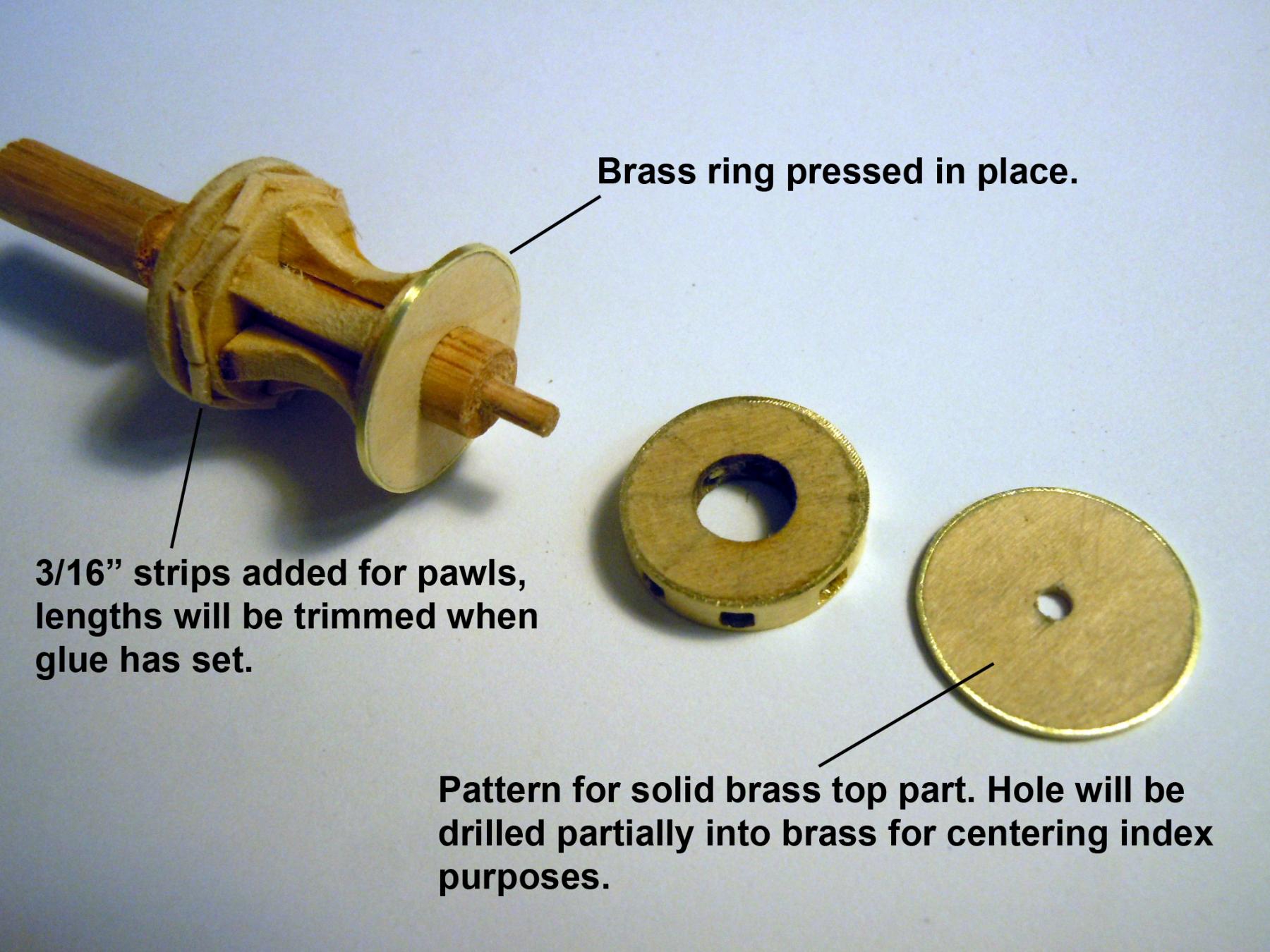
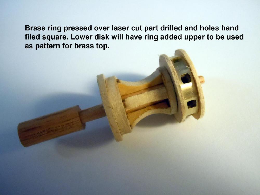
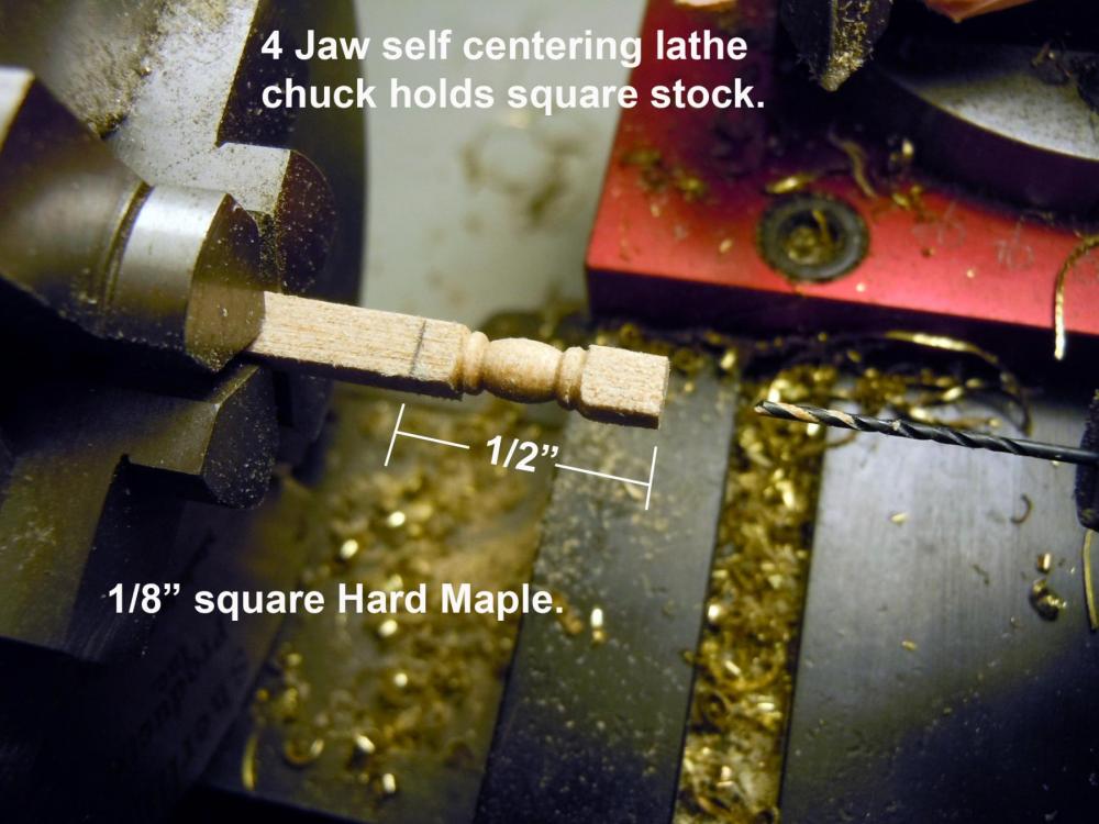
Jon, the top disc was hand cut and sanded and polished by hand. The pattern, the laser cut wood part with the brass ring was traced onto a piece of brass. The brass ring provided a hard smooth surface for tracing using a sharp scribe point and small center circle. The circle was drilled into the center mark but nor all the way through and thus the indexing point. Picture 4. I would highly recommend at some point acquiring a table top lathe; mine is a Sherline #4400 with the long bed. Also a 4 jaw self centering chuck for holding square stock. I am not a machinist; I am self taught on both the lathe and milling machine. Sherline offers a great book targeted at beginners to work with tabletop machines that they offer. Here are a couple of links. Explore their site and online museum to see some great work being done. http://sherline.com/product/44004410-lathe/ http://sherline.com/product/5301-tabletop-machining/
-
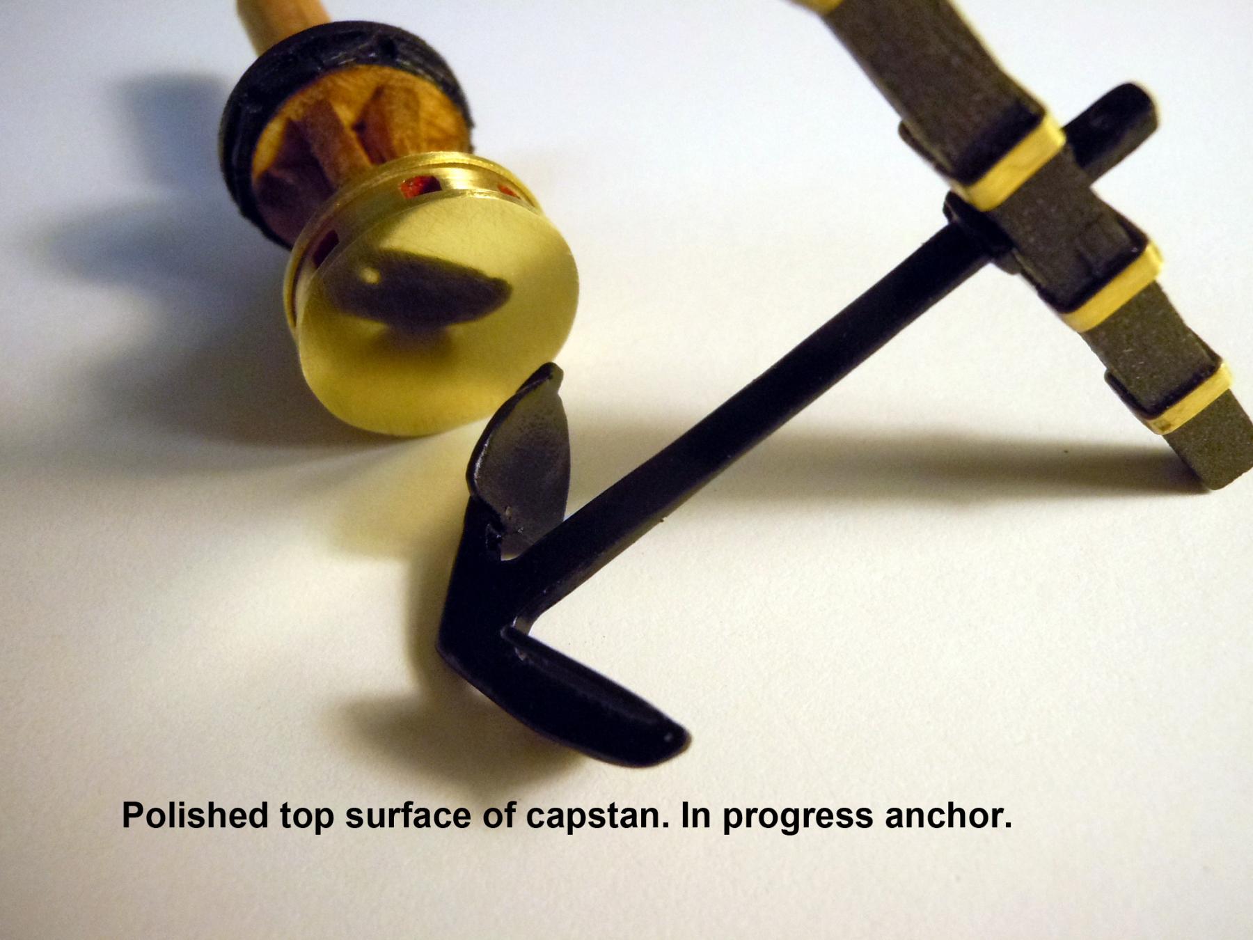
Al, no crown just a flat surface polished, what you may be seeing is the curved surface of the anchor. The brass was cut from 1/32" sheet stock to match the ring on the lower part.
-
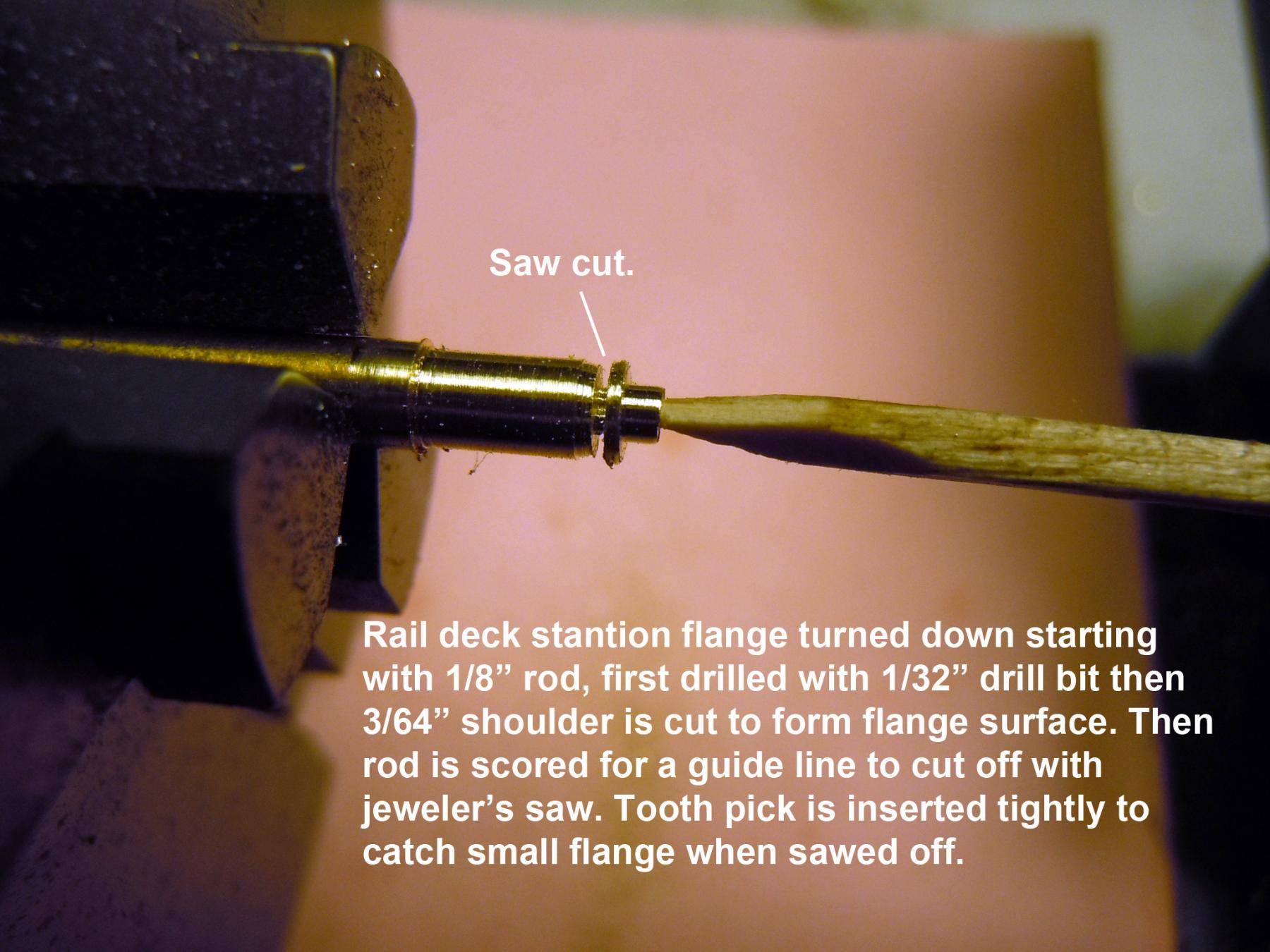
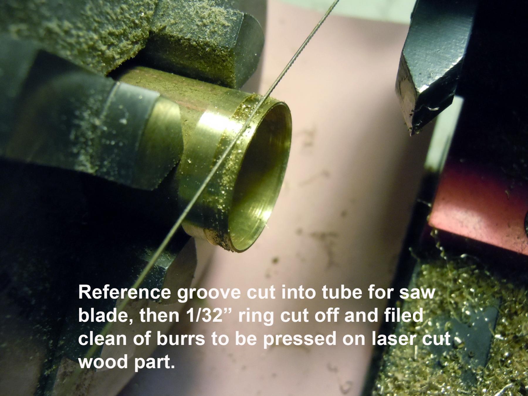
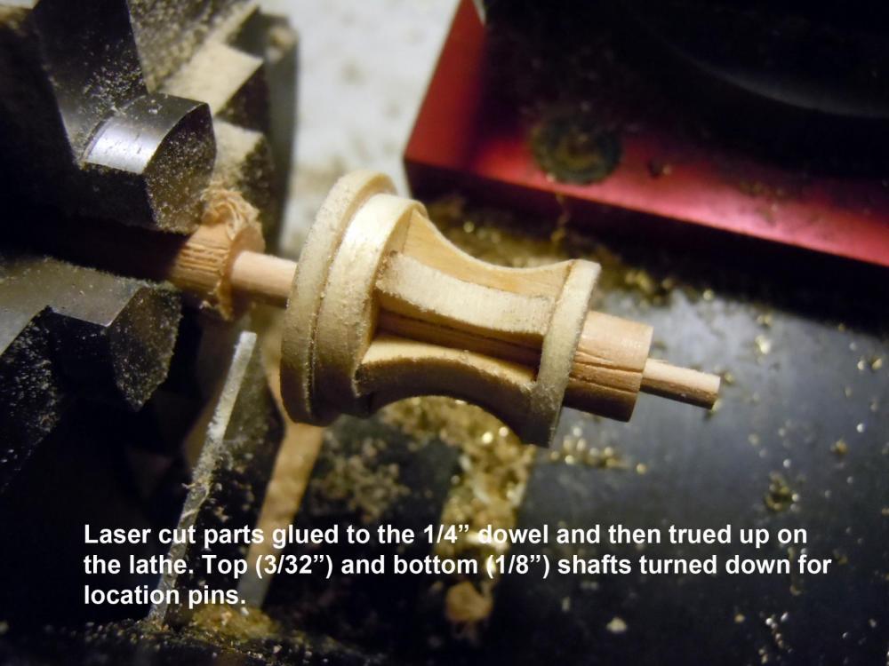
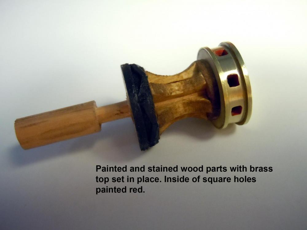
Thanks for your kind words! I moved onto the capstan and started the anchors to work back and forth. I again checked the photos of the real ship for reference since the plans and instructions are a little sketchy. The laser cut parts center holes for the dowel to pass through were slightly off center; so the parts were trued up on the lathe once glued together. I added brass ring and solid polished top as well. Here are a few pictures of what I did. It is very difficult to cut a thin ring off a tube with out tearing it up when the cut through happens; so I just cut a groove to use as a guide for the saw blade. This also shows an in progress anchor with metal straps added; the rest still need to be done. Note that the centering hole was not drilled completely through the brass top; the top wood pin was cut down to be used as an indexing pin into the partially drilled hole in the underside of the brass disc top. Back to the rest of the structures to be completed.


-
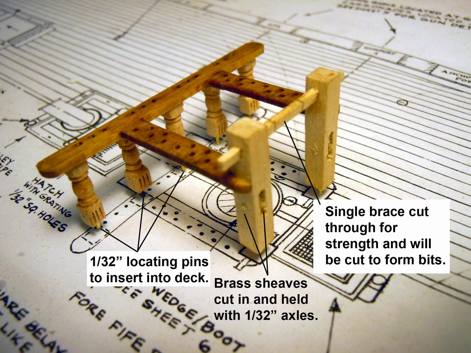
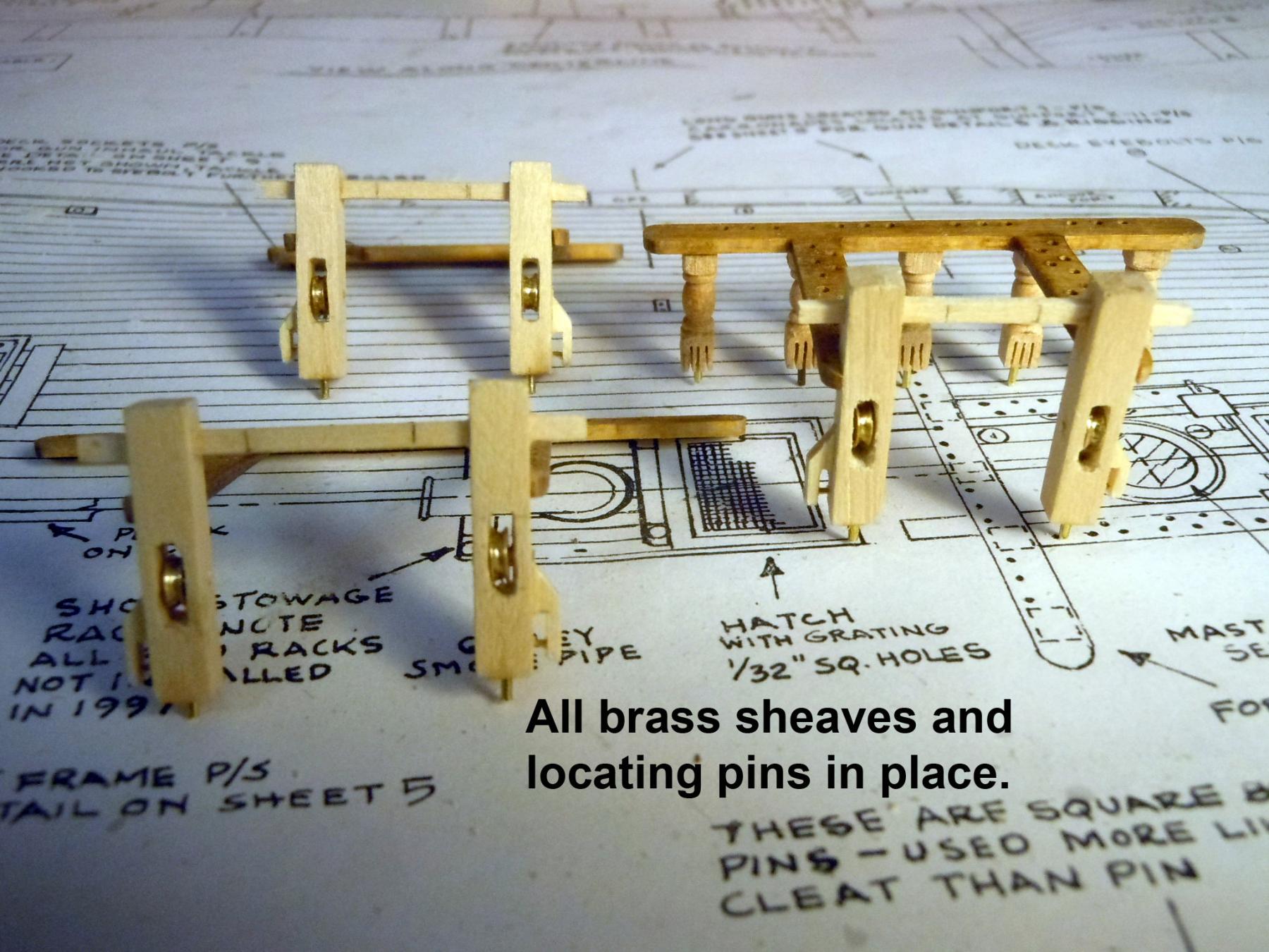
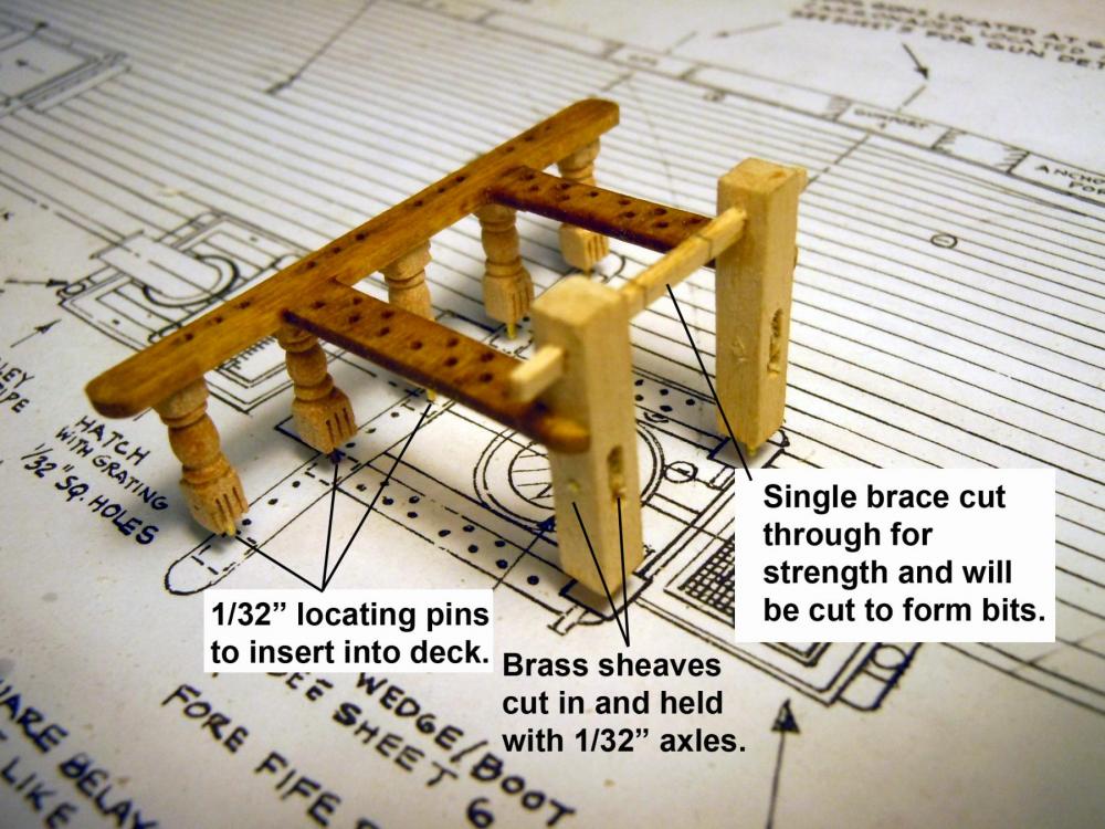
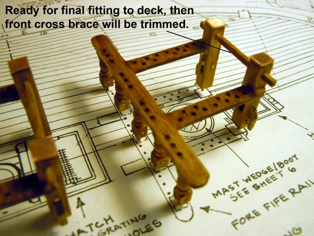
Finished up building the three fife rails. One word of advice for those who follow cut in the front brace to the forward posts as noted for strength due to the weakness of the laser cut arm parts with holes having a tendency to break very easily while handling. They also will be able to hold the posts in place to locate holes in the deck for the locating pins. These braces will have the center portions cut away once the fife rails are finally glued in place. As for now all the spar deck structures will be fabricated and set in place for now including the deck itself. I also cut sheaves on my Sherline lathe to be cut into the posts with a 1/32" axle for turning if necessary. Here are a sequence of pictures. I then started at the bow with the structures and am working towards the stern, which will be a slow going process since most will be scratch built like these. Now back to building.


-
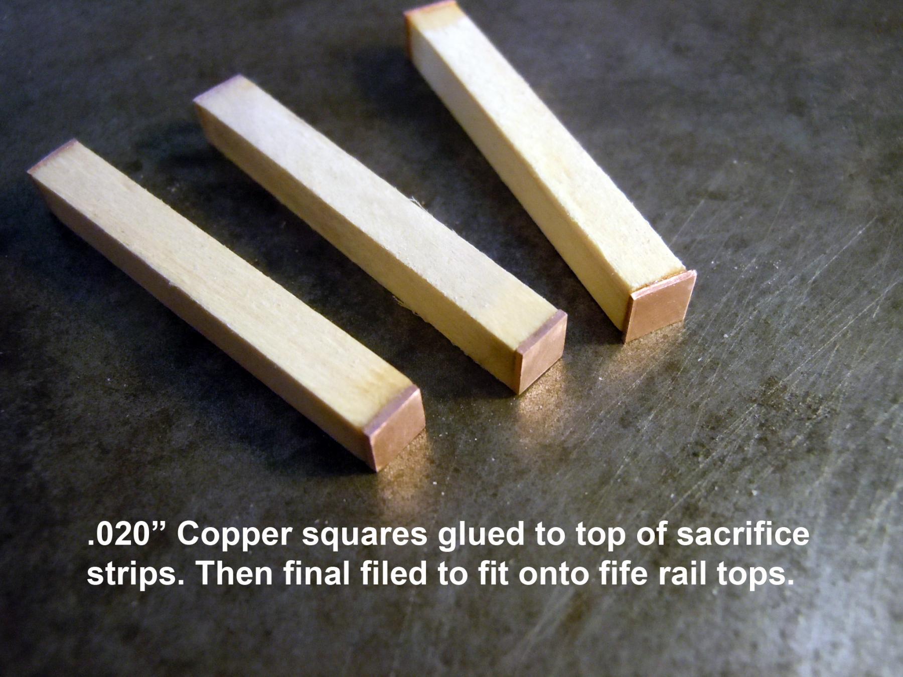
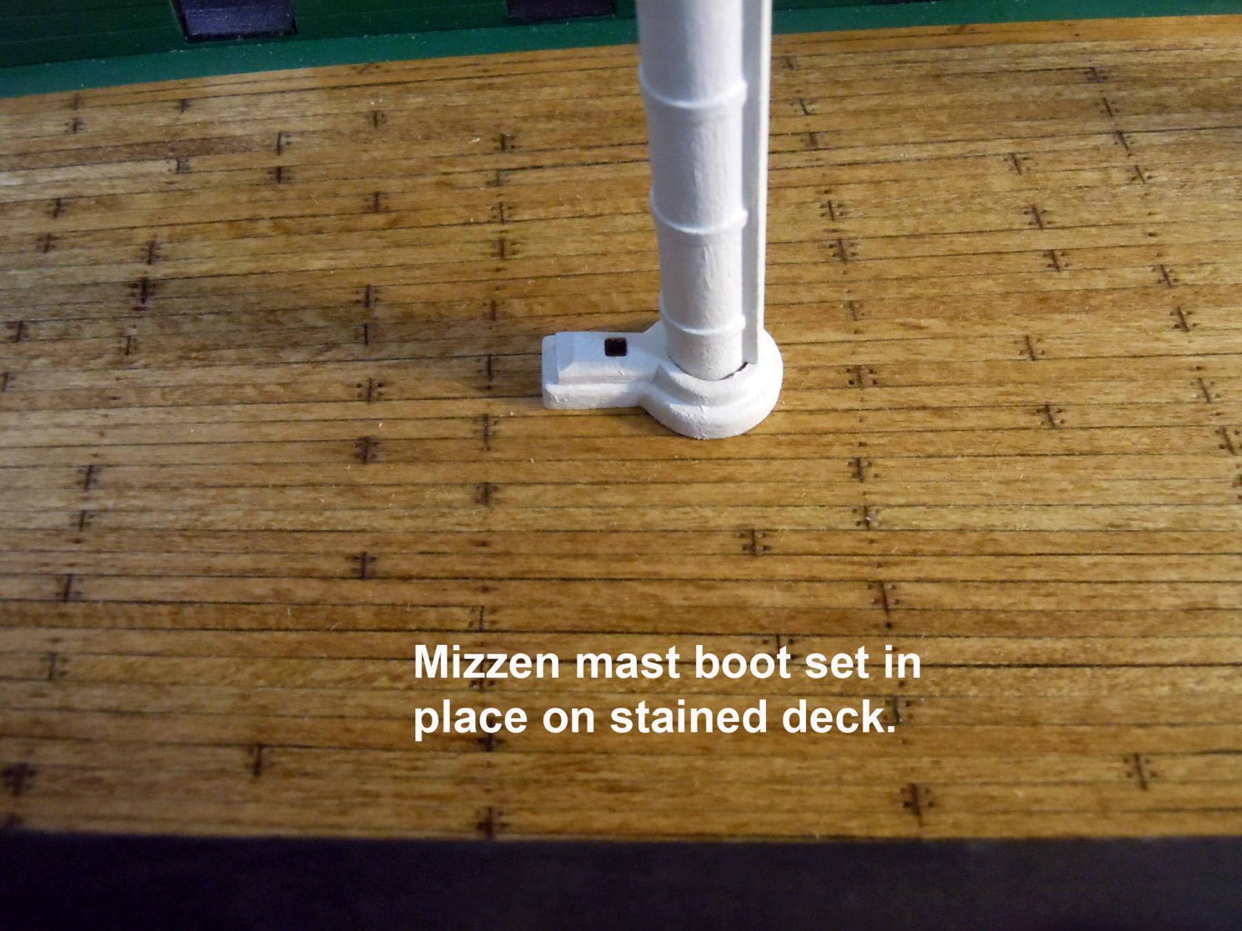
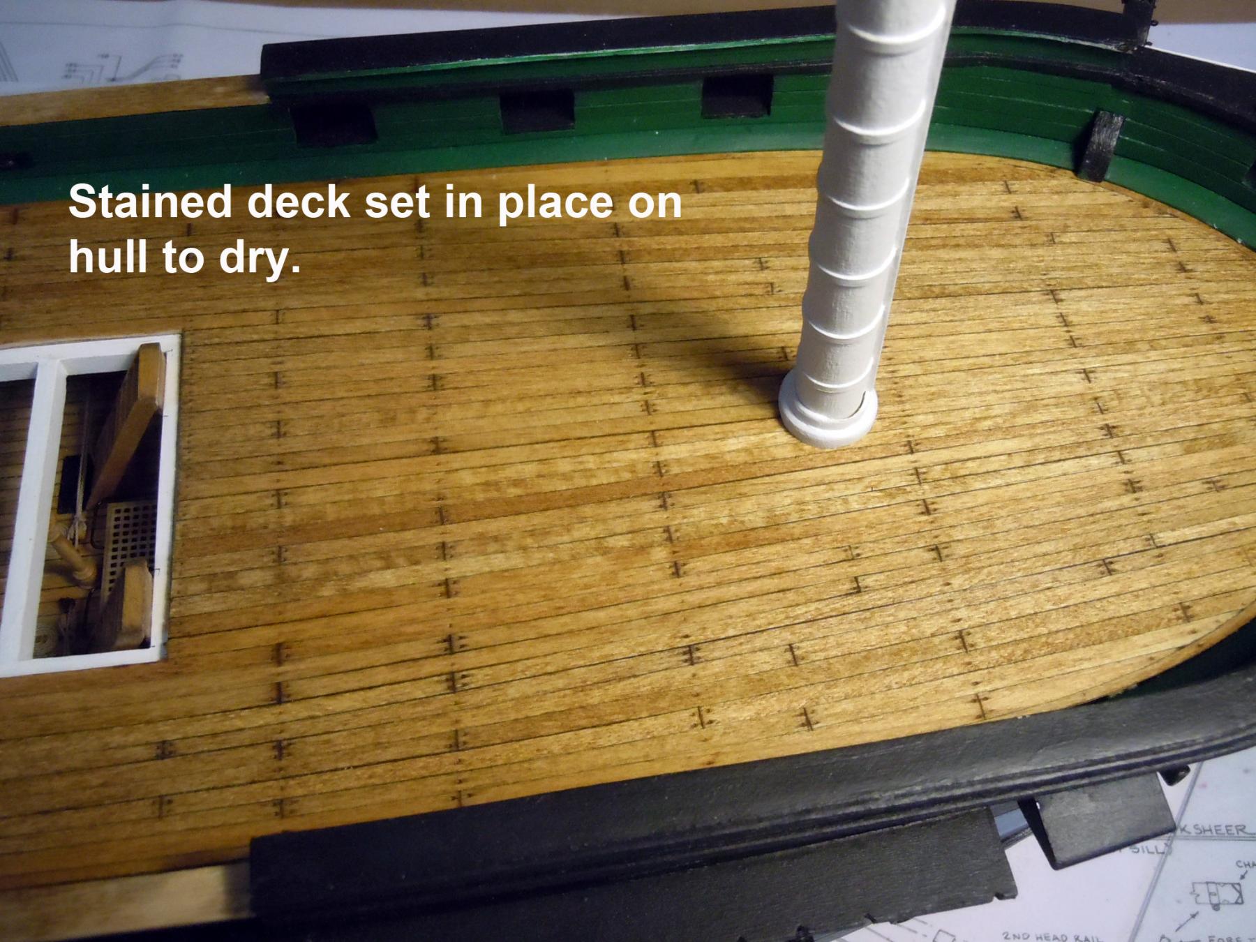
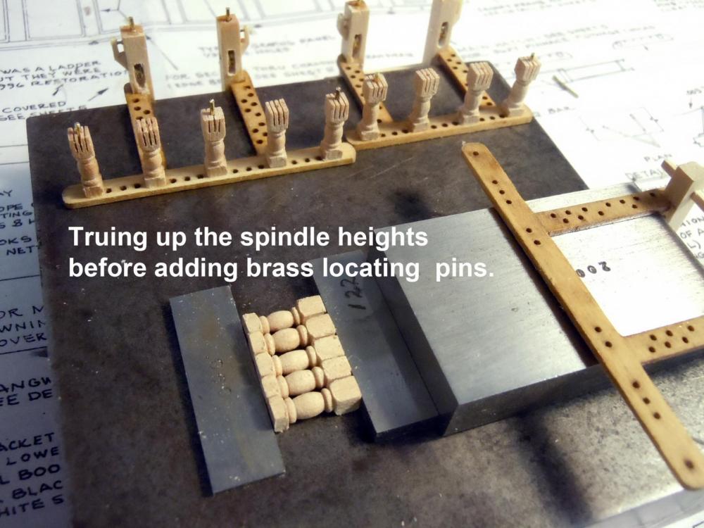
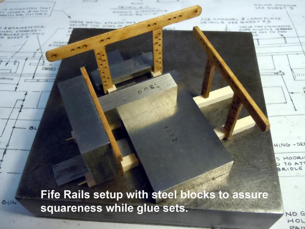
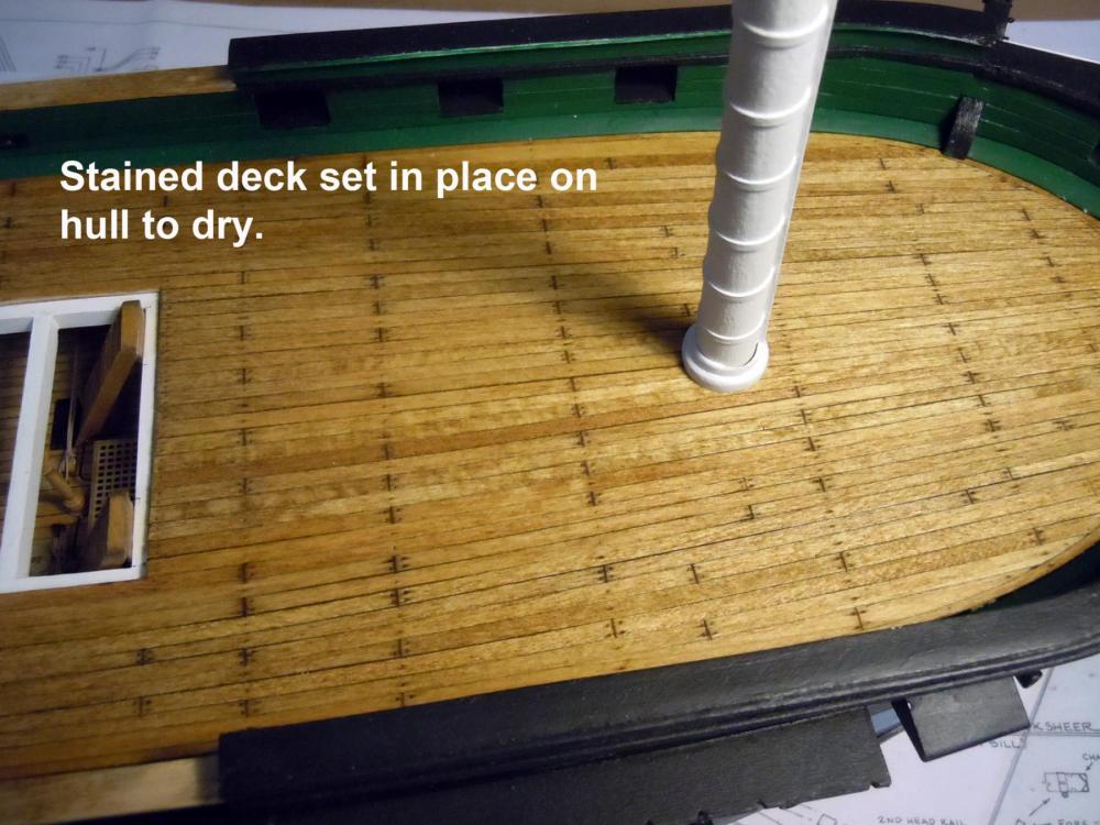
Had a great getaway weekend in the Sierra Nevada Mountains and the Sequoia National Park. Those Sequoia trees are huge! I could not imagine how many model ships could be built from just one. Now into serious babysitting of grand kids as the wood flooring is being installed and sanded. Soon we will be heading out to the zoo for the morning. I have had an opportunity to do a little work and finished up the spar decking and stained it Golden Oak. I then installed it back on the hull with the wedges to dry. I am still trying to sort out the 1/32 raised planking section towards the stern from the capstan back to the mizzen fife rail. Any insight on this detail is welcome since it does not appear on the real ship; but need to resolve it before adding the structures. In the meantime I made the mast boots and started on the fife rails and have decided to turn the supports rather than using the kit's castings. I am using maple for these since they will turn better and hold the details such as the saw cuts for the sheaves. I also am adding the sheave pins using .020" brass rod. Here are the boots and decking sections so far. Here I am starting the fife rails and using steel blocks to assure squareness as glued together. Here is the test turning and also note the 1/32" drill bit on the right for the location pin to index into the deck. Will be working away on the turnings since 14 are needed.

-
Darrell, I am sure you may already know of Keim Lumber in Charm, Ohio, but if you do not a must visit. They have a great selection of exotic woods from around the world and also have a chops box of these woods with some great finds for model building at reasonable prices. Well worth a visit! Back on my computer here is a link. Just wish we had a place like this near us in California. http://www.keimlumber.com/exoticwoods
- 648 replies
-
- 3
-

-
- niagara
- model shipways
- (and 1 more)
-
Darrell, glad to hear that you are moving along in your build. I am also learning as I go as well since this is only my second ship build. My wife use to do the big craft show in Zoar on the square. We use to live in Wooster, Ohio before moving to Morro Bay to be close to our granddaughters and be able to help with them when mom and dad are working.
-
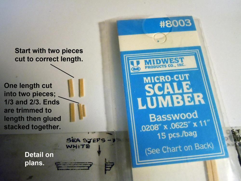
Jon, yes the pieces are stacked and I used Midwest Scale Lumber #8003 two lengths were cut then one split into 1/3 -2/3's and then the ends trimmed to length. All then carefully glued together, once set the ends of the top rounded by sanding. As for the plans yes they show a detail of the three parts even though the side elevation shows only two. Could have been intended or a drawing opps. Here is a picture. Here they are painted and installed on the starboard side. I have notice so many dependencies in the plans I am now only using them as a guideline and do research based on vintage and contemporary photos. Being basically a scratch builder and have always done my own research and drawings of model subjects and experience tells me not to trust drawings of others even the self proclaimed experts; I am probably building a composite of all three based upon the details I personally prefer. This build will be a gift to my son when completed and end up in his house at the end of Long Island. Heading out after lunch here to have a get-a-away weekend in the mountains with the kids and grand kids. Completely off the grid in my son-in-laws's family cabin.

-
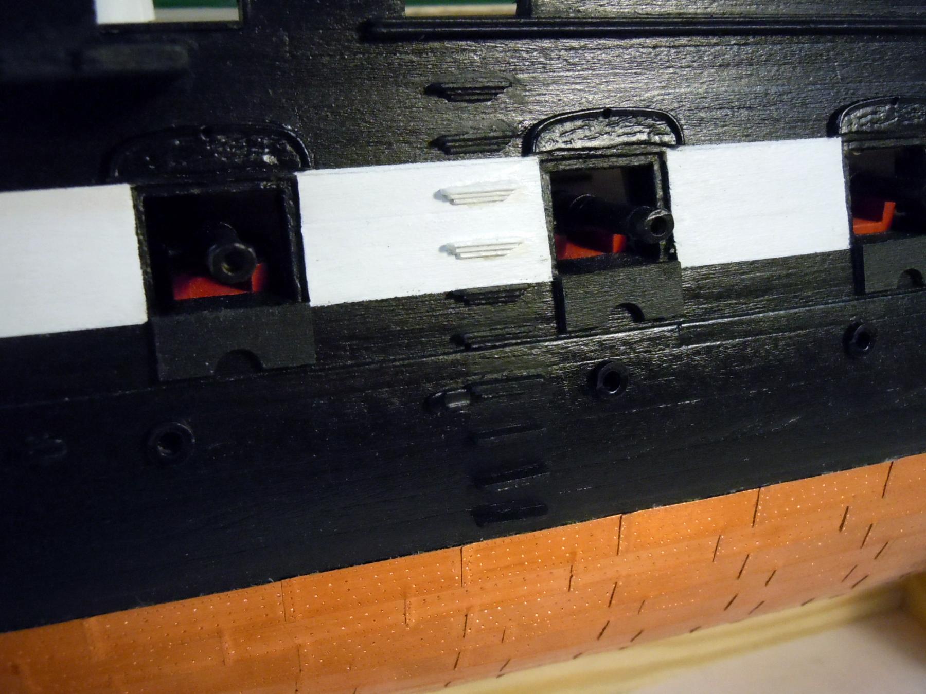
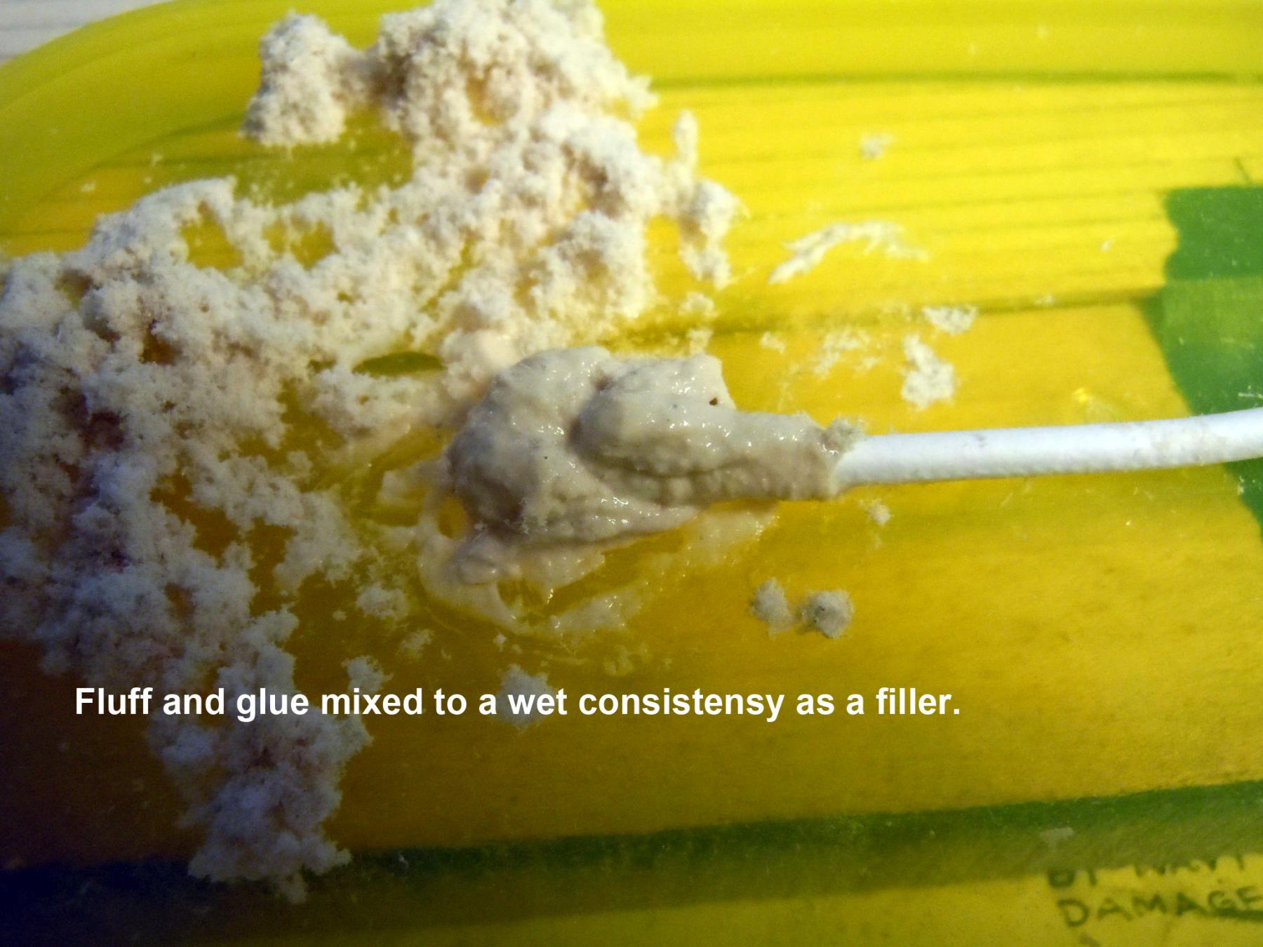
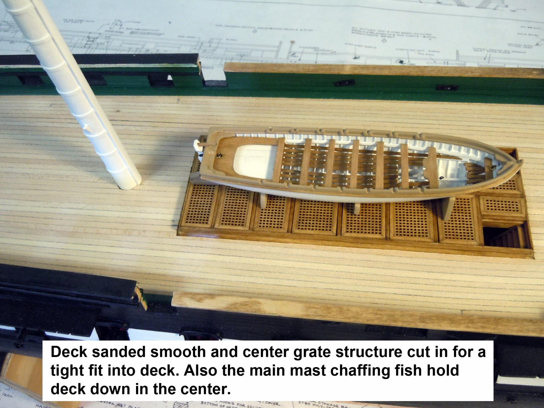
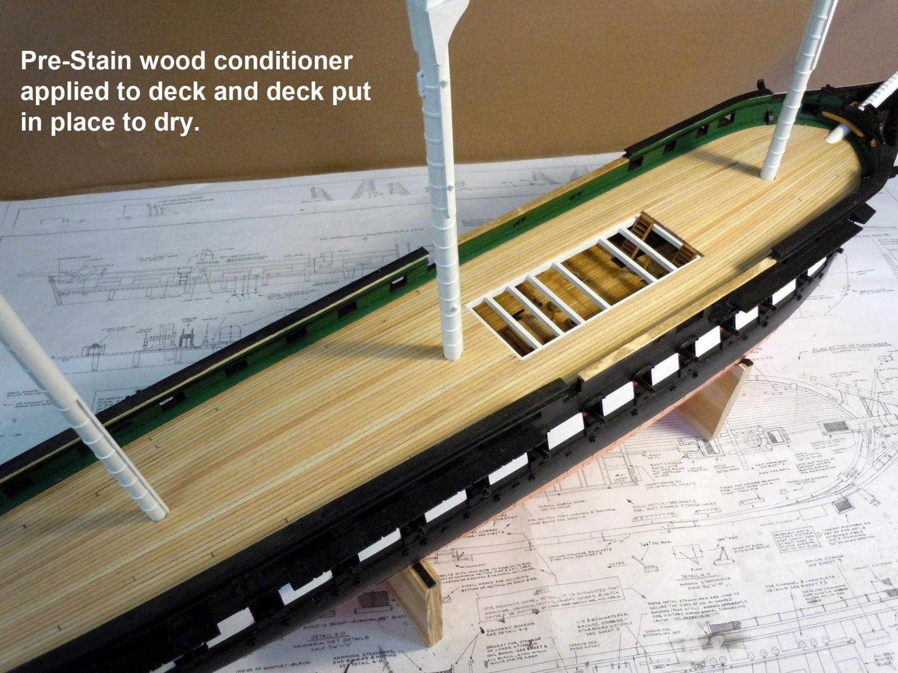
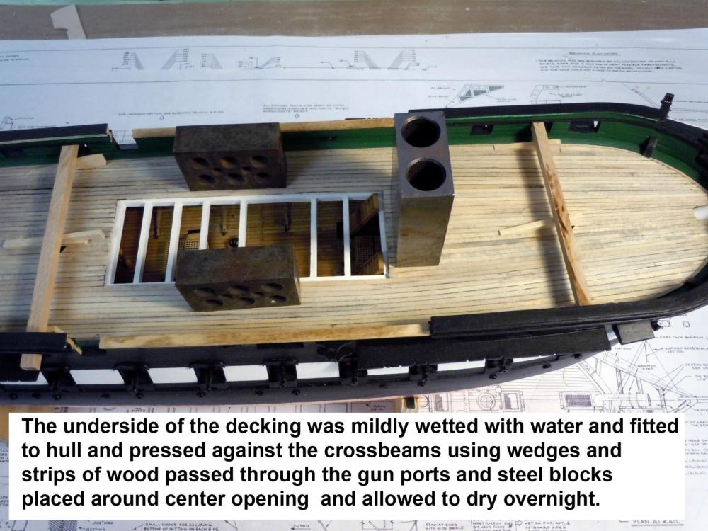
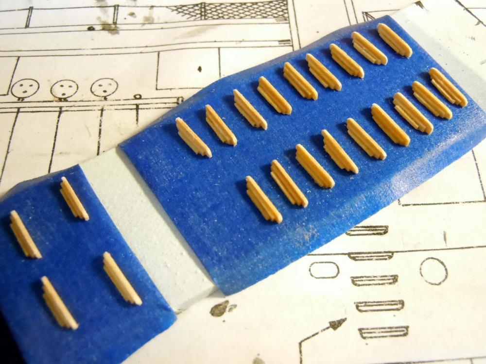
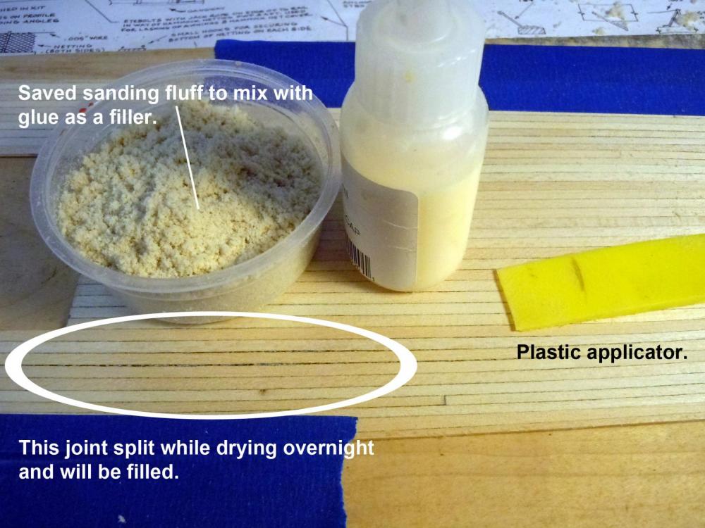
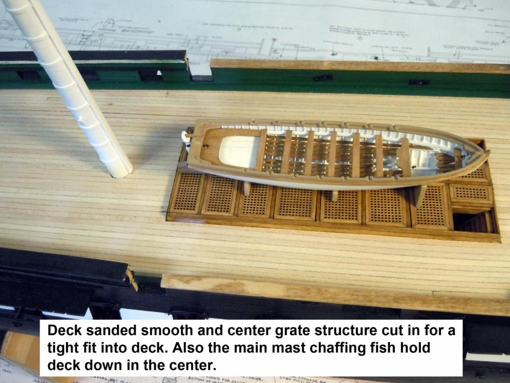
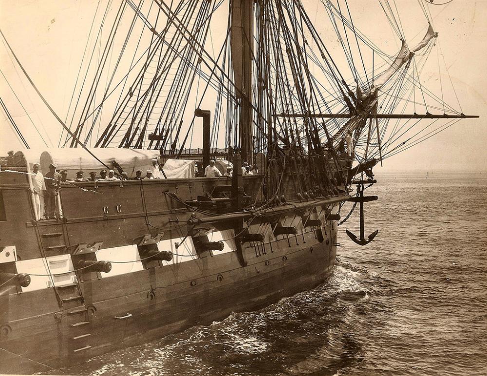
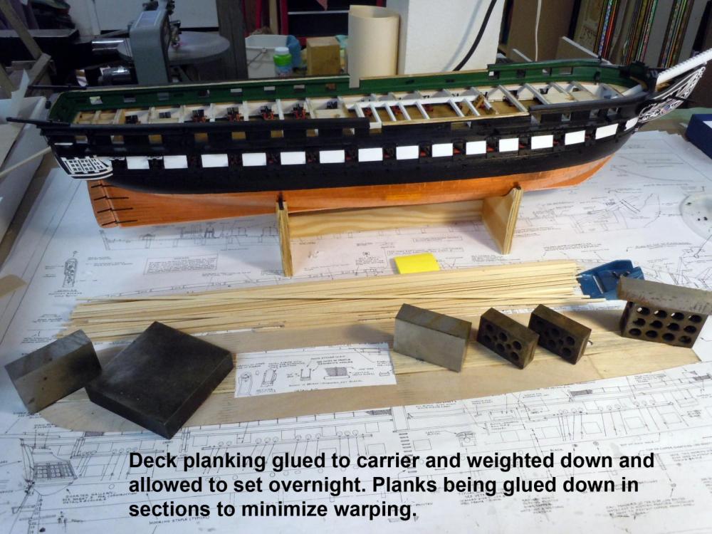
I continued on with the deck by mildly wetting the underside plywood carrier to counteract the warp from gluing and set in place in the hull and held in place with wedges under strips of wood inserted through the gunports and weighted down with steel blocks around the center opening and allowed to dry overnight. This process of using wedges and weights will also be used to glue down the deck when the time comes. In the meantime while waiting for the deck to dry I fabricated the sea steps and in checking vintage photos versus plans. The plans show 11 while photo shows 10, and there are only two painted white that are in the gun stripe. Here is the vintage photo. I will use this reference to do mine and I will also add the hand ropes along side of the steps. Here are the sea steps ready to paint. I made a couple of extra just in case. While drying over night one of the joints let go that I fixed with filler made from the sanding fluff I saved while sanding the deck. Here the filler is applied and the key is to apply it across the planking joints for the best fill. Allow the first coat to dry and then apply a second. Once dry it was sanded to match the surrounding area. Here the final trim cut in of the grate structure was done using a sharp blade carefully slid along the edge of the frame side to cut deck. Care must be used to cut the deck and not the frame; a very slight angle of the blade away from the frame helps. Here the pre-stain has been applied and the deck put back in place to dry with the mast chaffing fish holding the deck down. Now back to adding the steps while the conditioner drys.


-
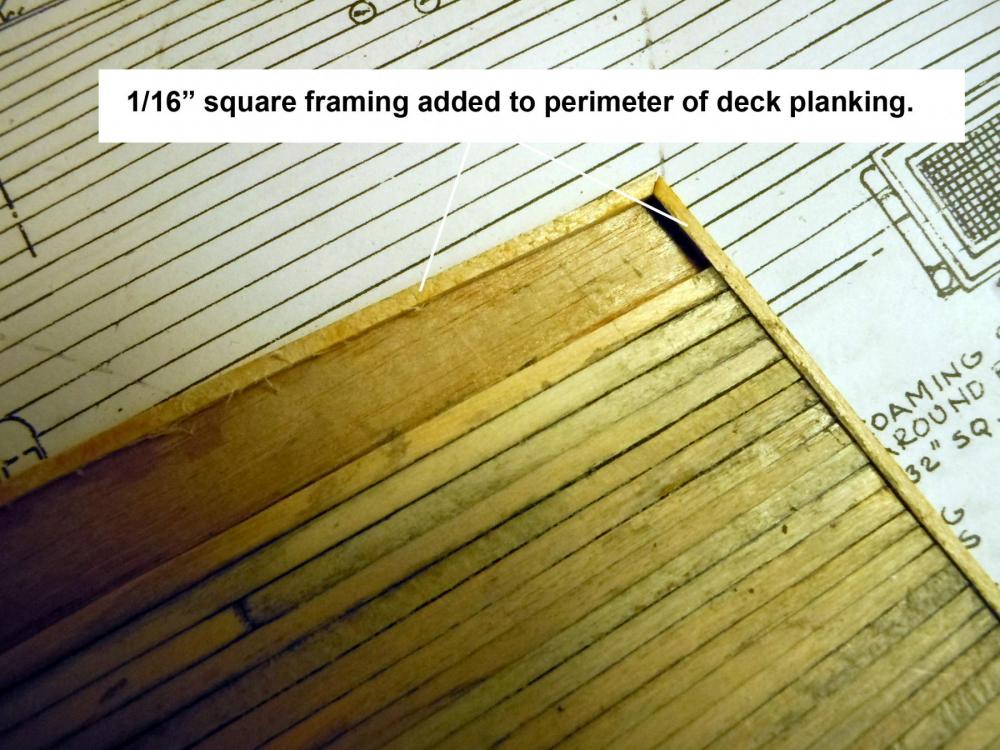
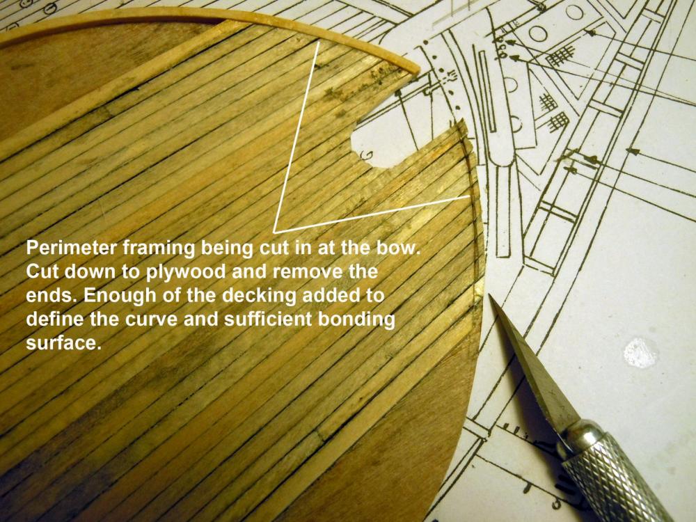
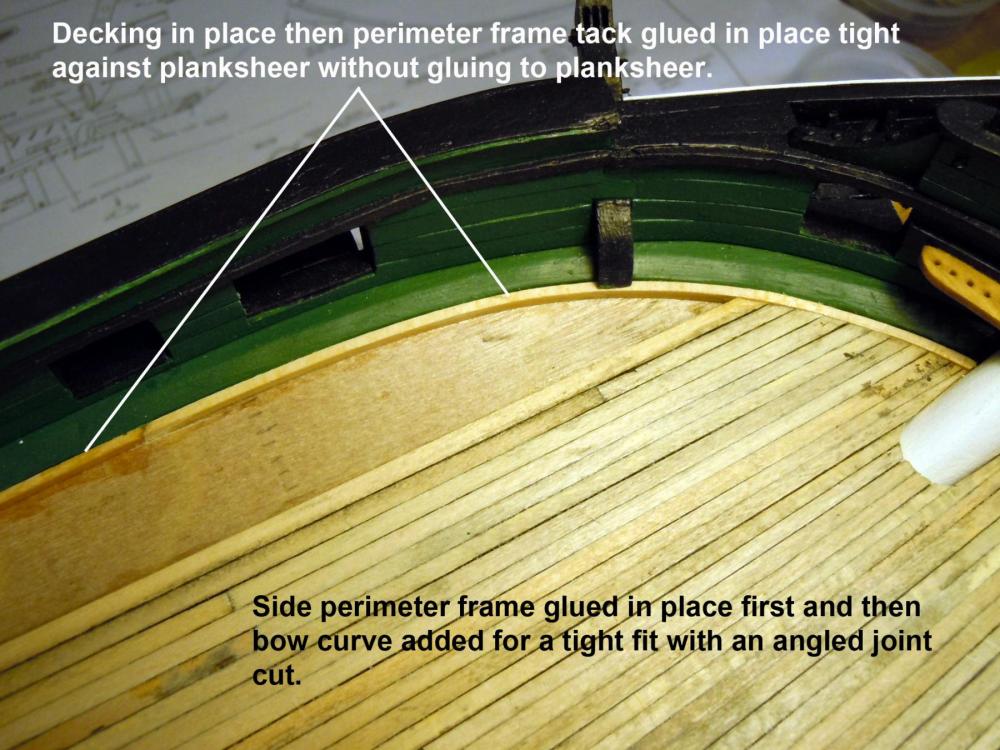
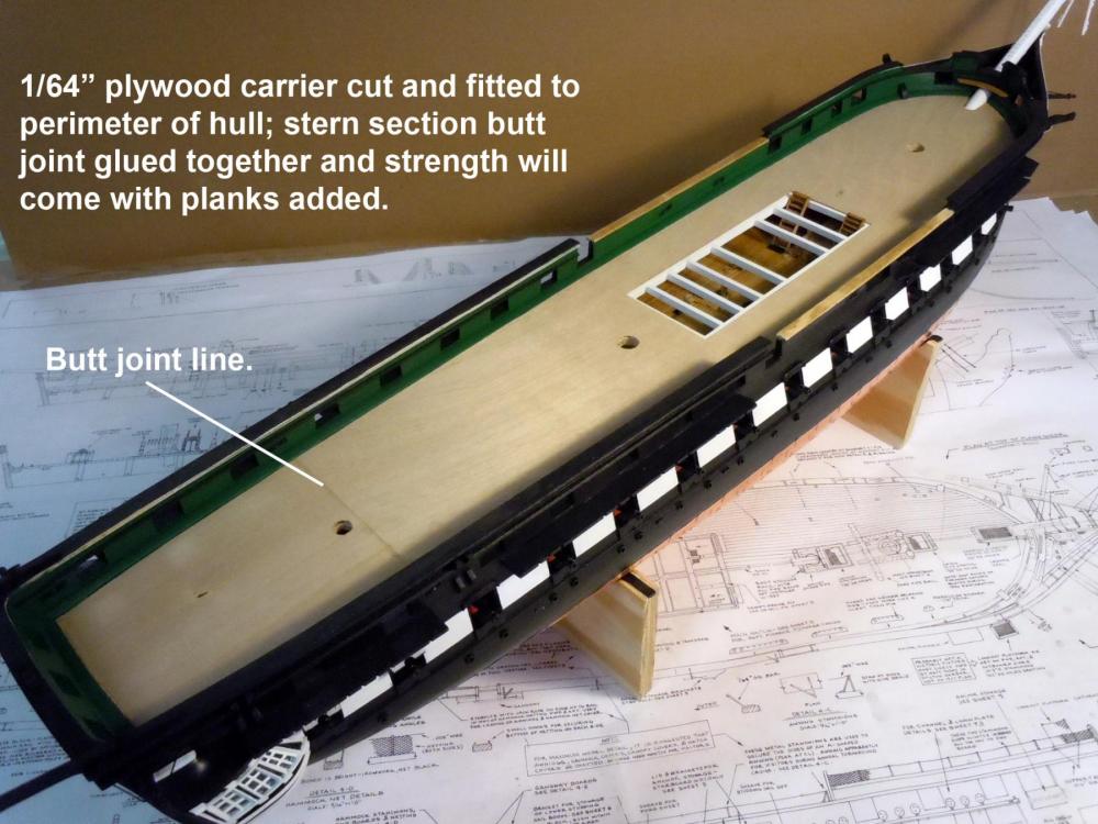
Once the center planking was set I was checking spar deck pictures of the real ship and noticed that there was a trim perimeter frame between the decking and planksheer. Fortunately the center decking section allowed the cutting in of the stern, and bow portions once the sides were added. The framing was added with the decking in place with the perimeter framing being held tightly against the planksheer and then very carefully tack glued without gluing the frame to the planksheer. Decking was then removed, the framing securely glued and the rest of the planking added. Once the glue has set the planking will be sanded and the butt joints cut in with a sharp Xacto blade and black glue filled. Staining will then follow.
-
Mike, thank you for your kind compliments! Matt, in rereading your comment I think you meant 3/64" rather than 3/32". I am using the 1/16" as supplied by the kit on the shaved spar deck laser cut parts as I also did on the gundeck to assure correct height for the long guns and carronades.
-
Matt, as I commented above that the laser cut parts were shaved to compensate for the thickness of the 1/64" carrier for both decks.
-
Jon, yes this is my way of doing it not the plans and very early on I shaved the laser cut bulkheads to compensate for both the spar deck, as well as the gundeck just for the the very reason you are pointing out. I also did this on my Niagara build as well.
-
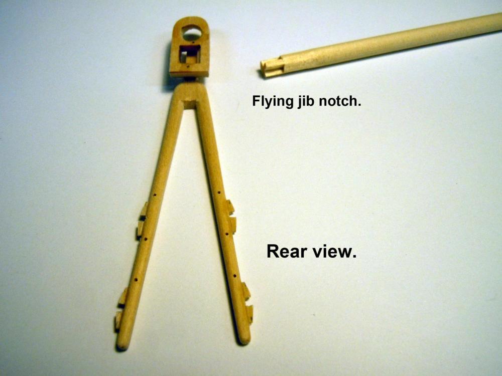
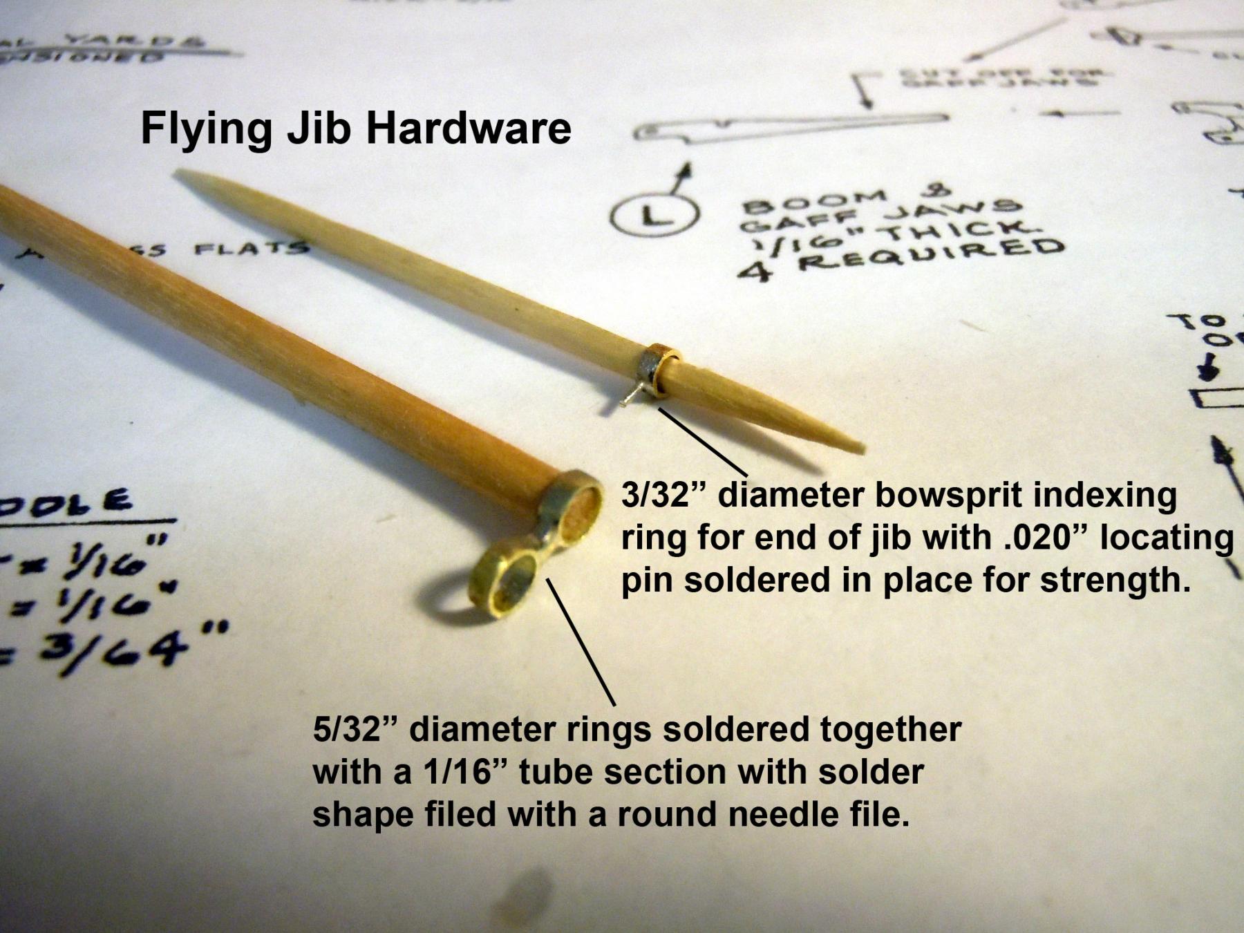
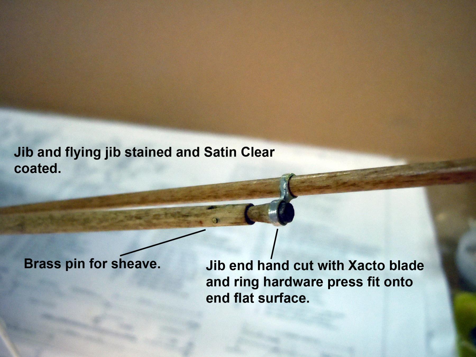
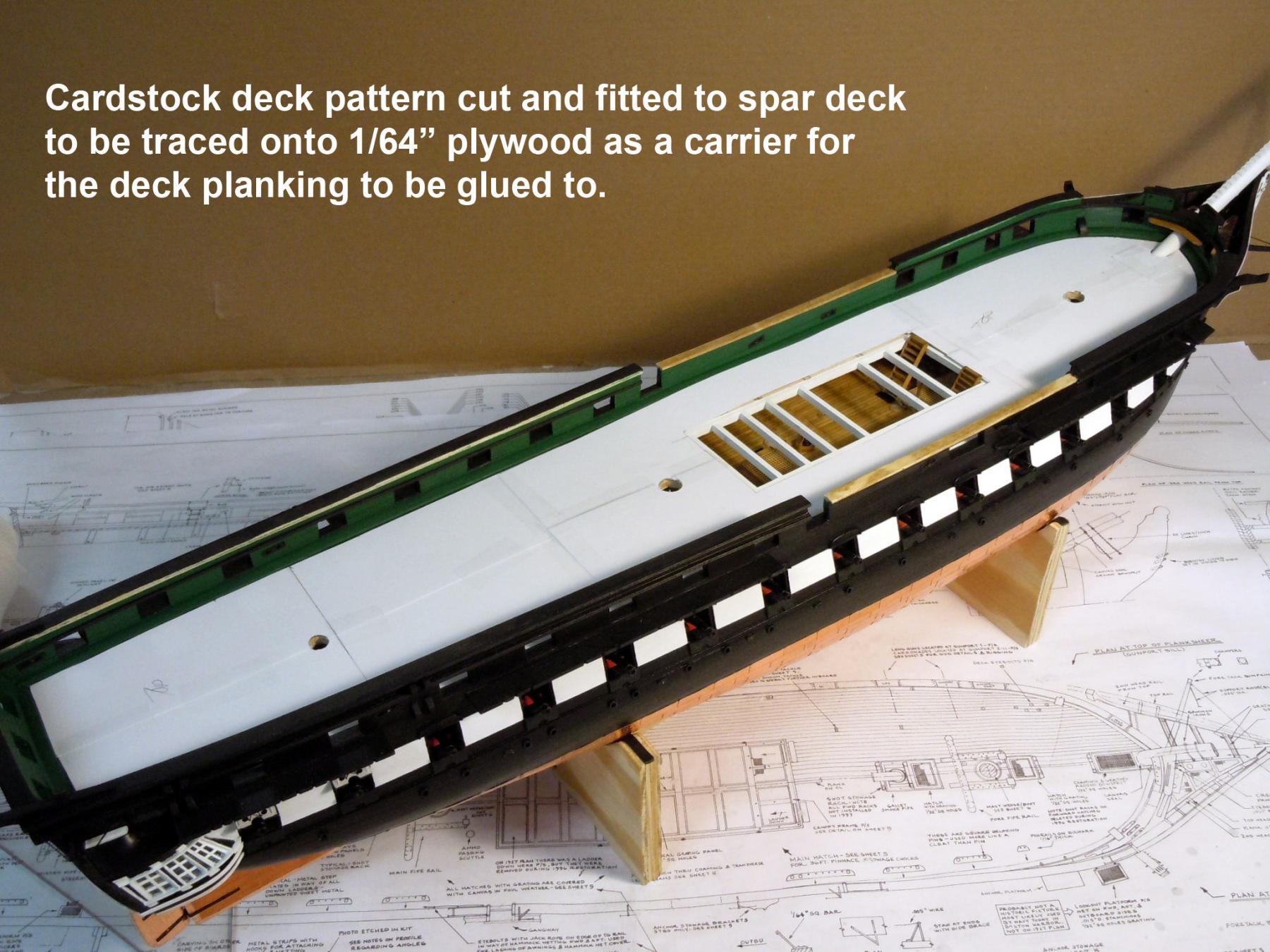
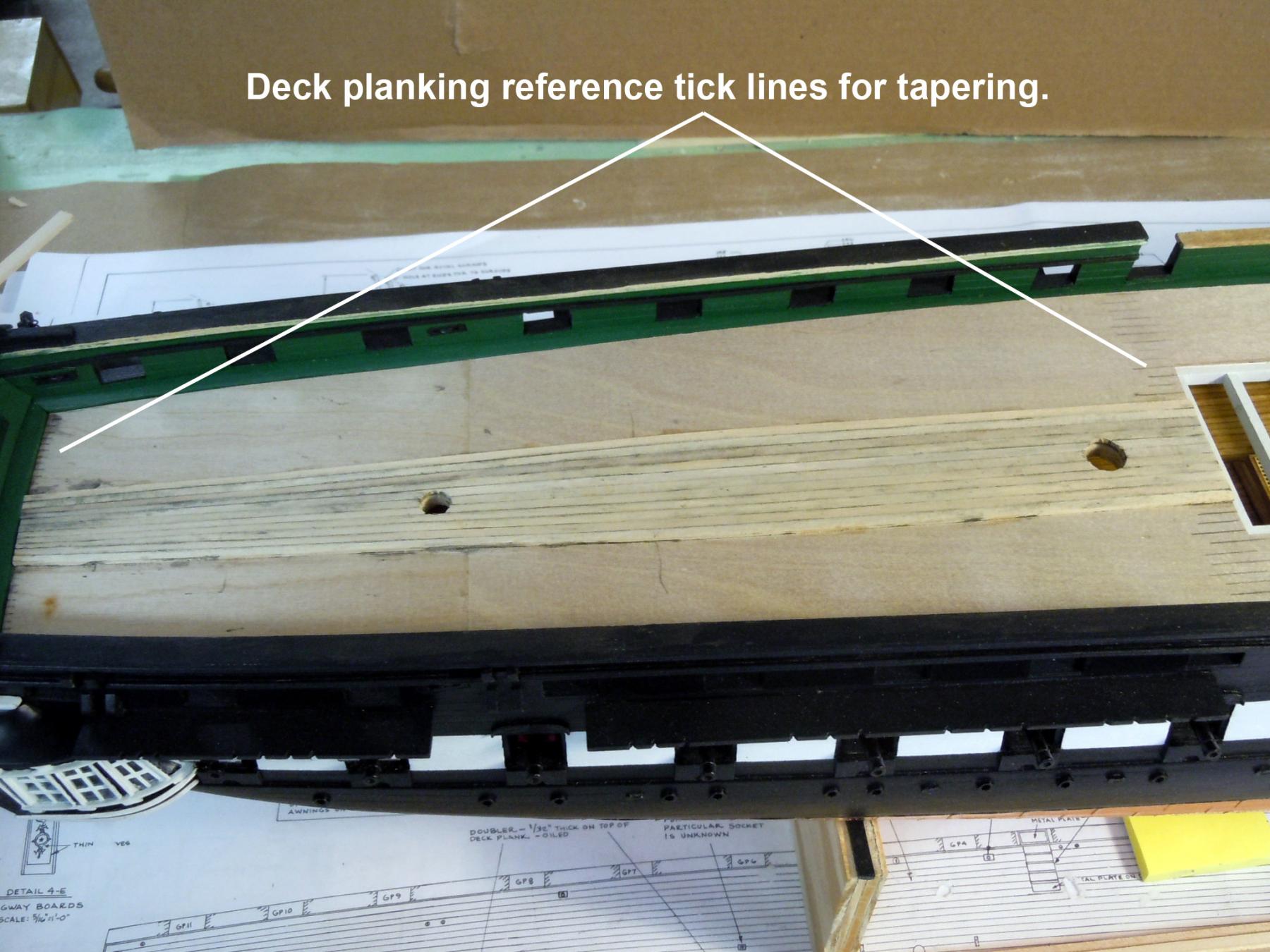
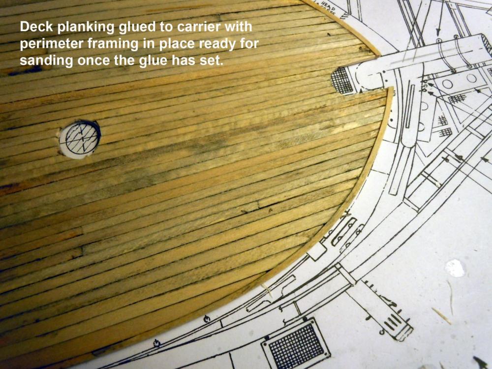
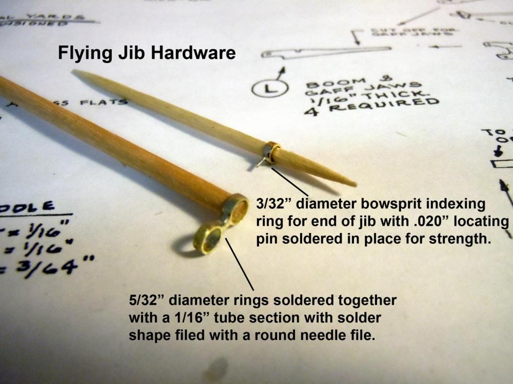
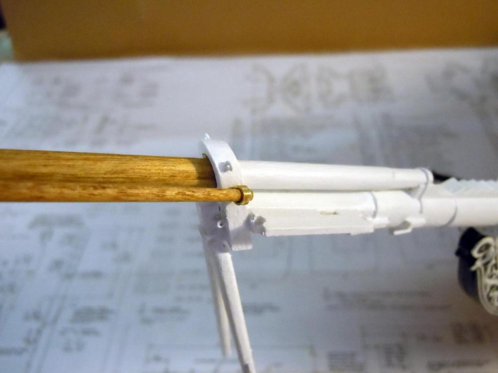
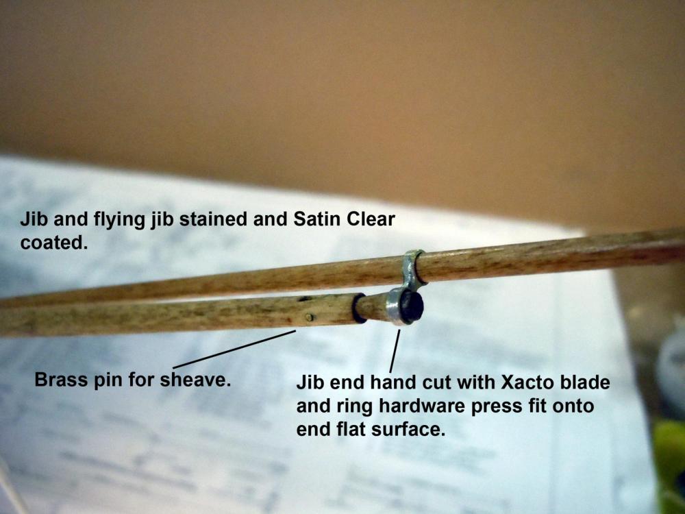
My contribution to the house renovation work is done so back to some ship building. I finished up the flying jib hardware and gundeck detailing and am moving on to the spar deck planking. I decided to use a 1/64" plywood carrier for the planking due to the hole needed for the center grating area. First I made a card stock pattern then traced it onto the plywood and added reference tick marks for tapering the planks. I am using black glue that will show as the joint lines. Planks will be shaped and glued individually for each position. The hardware parts will be painted black before adding. Here the rope coils were added for the in haul lines. Now back to adding decking to the carrier and sorting out what bracing may be needed to glue the carrier to the hull.


-
David, glad to see the problem solved. I have had a busy week dry walling, wife's craft fair, and yesterday my son had twin boys in NYC. Life is good and all are doing well.
-
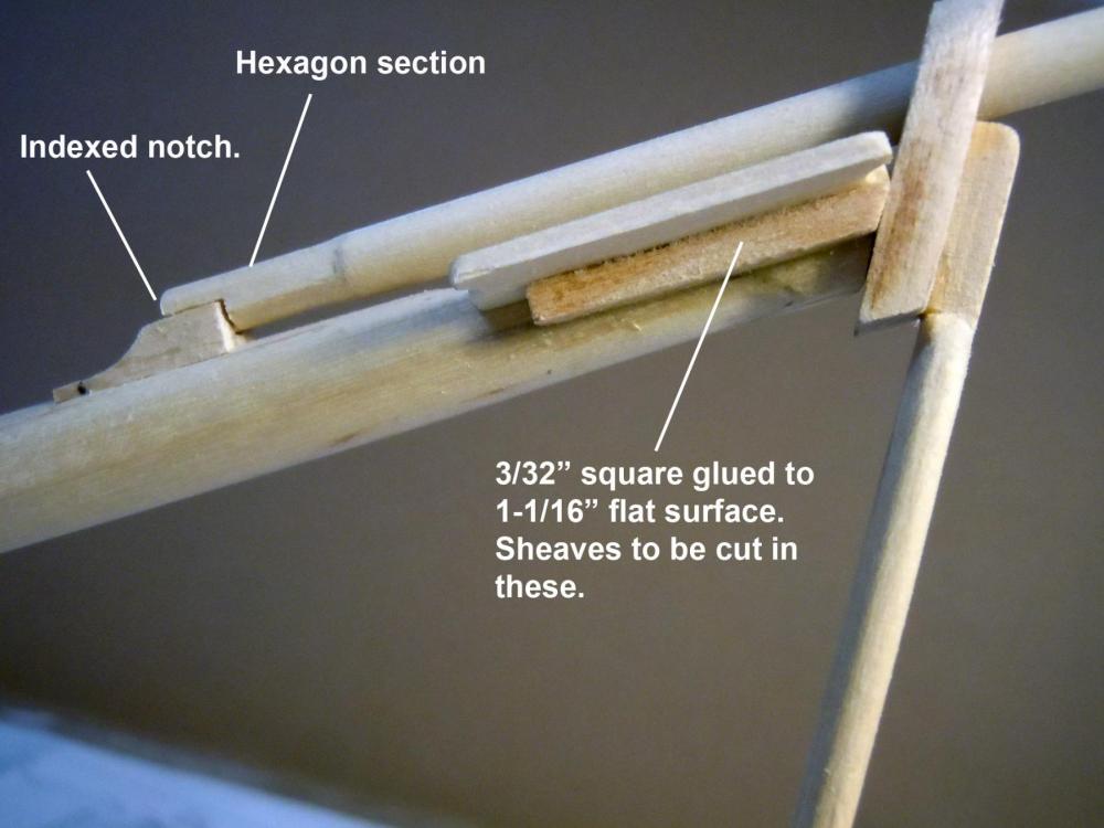
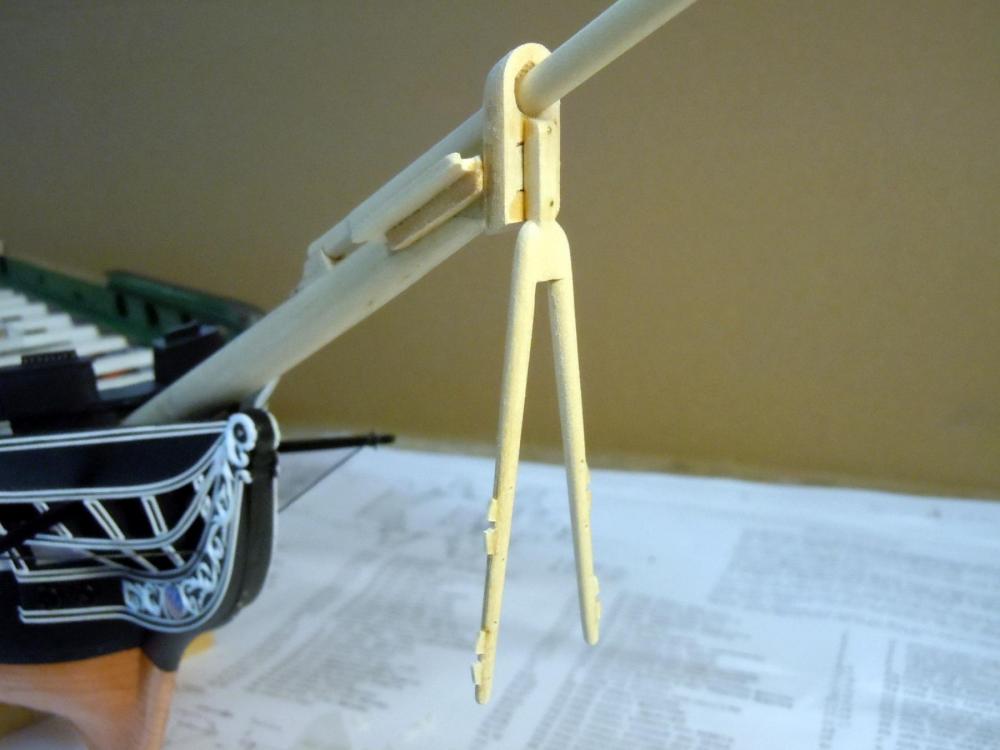
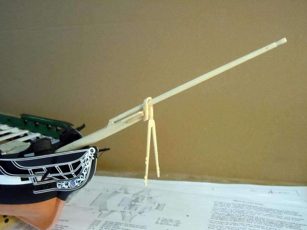
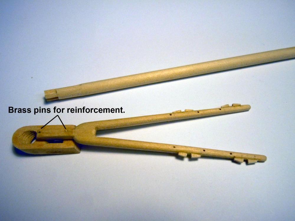
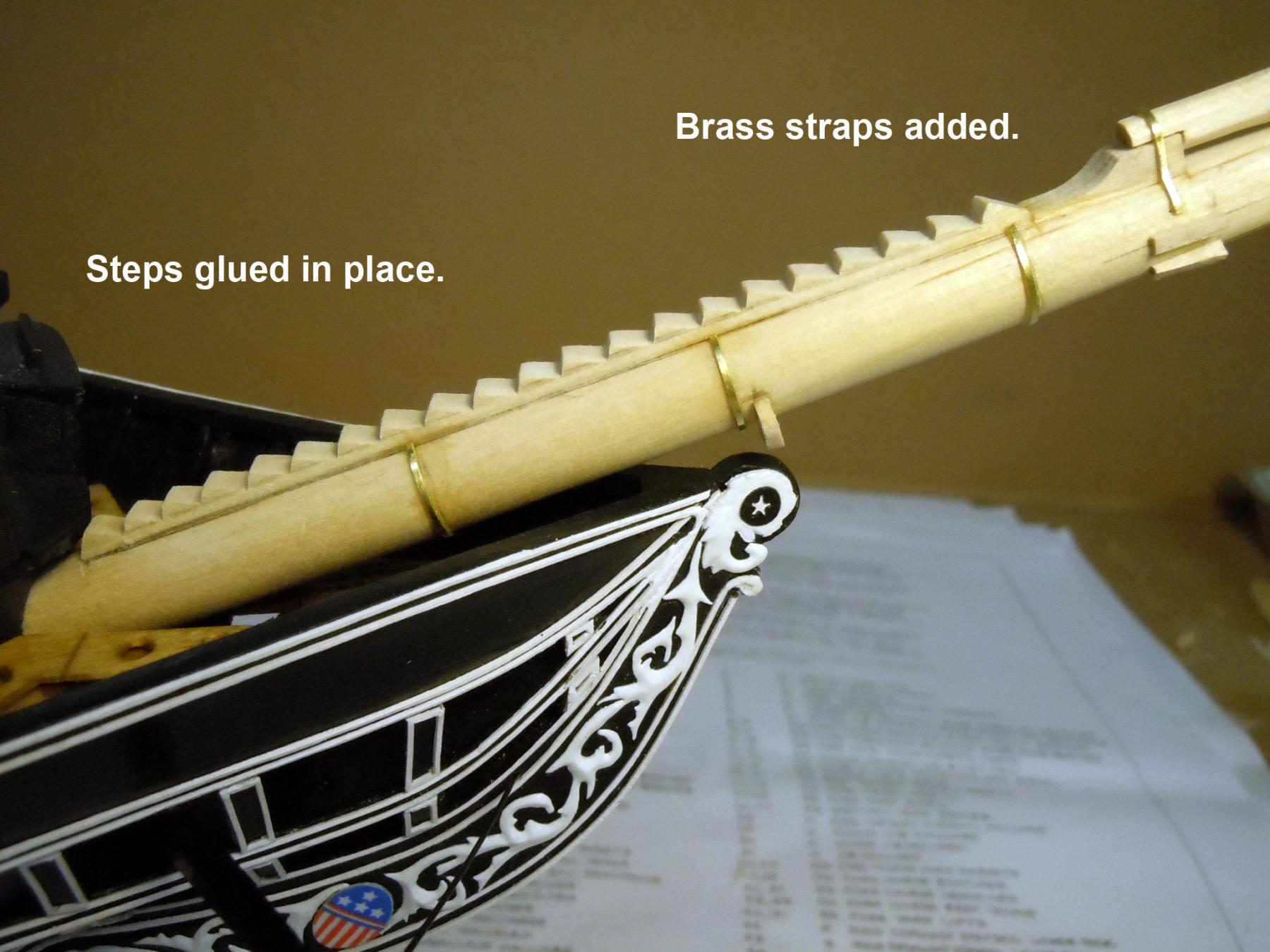
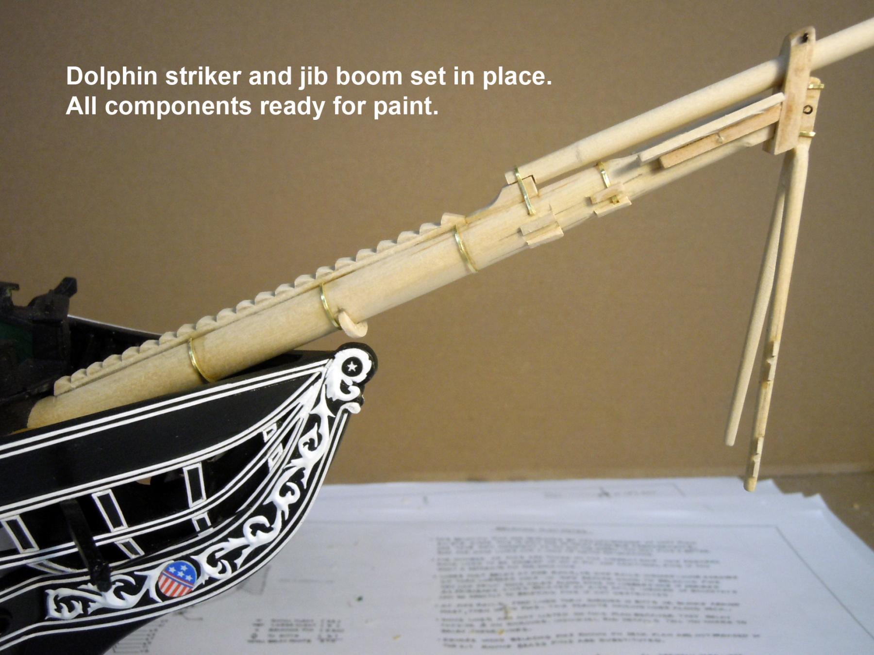
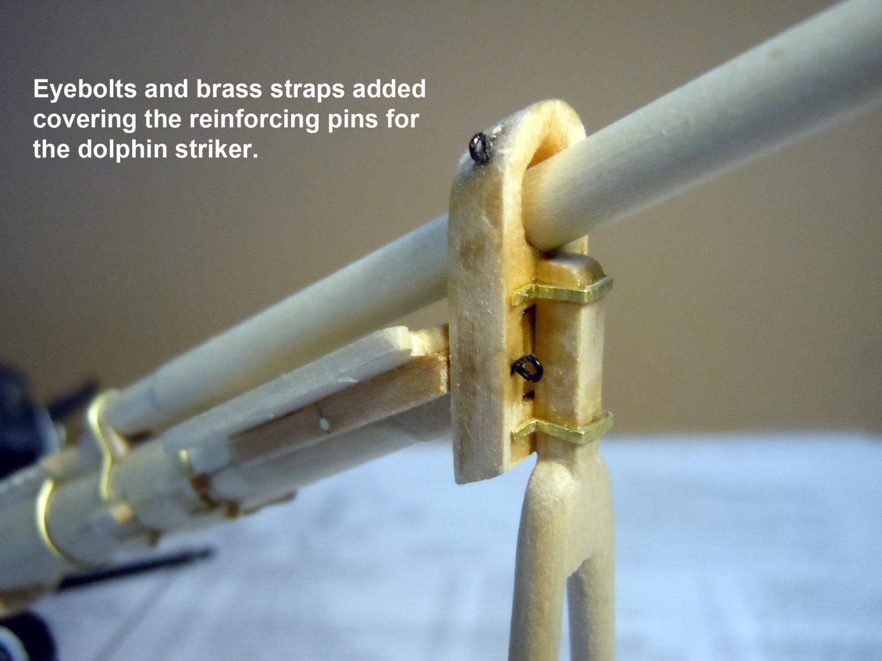
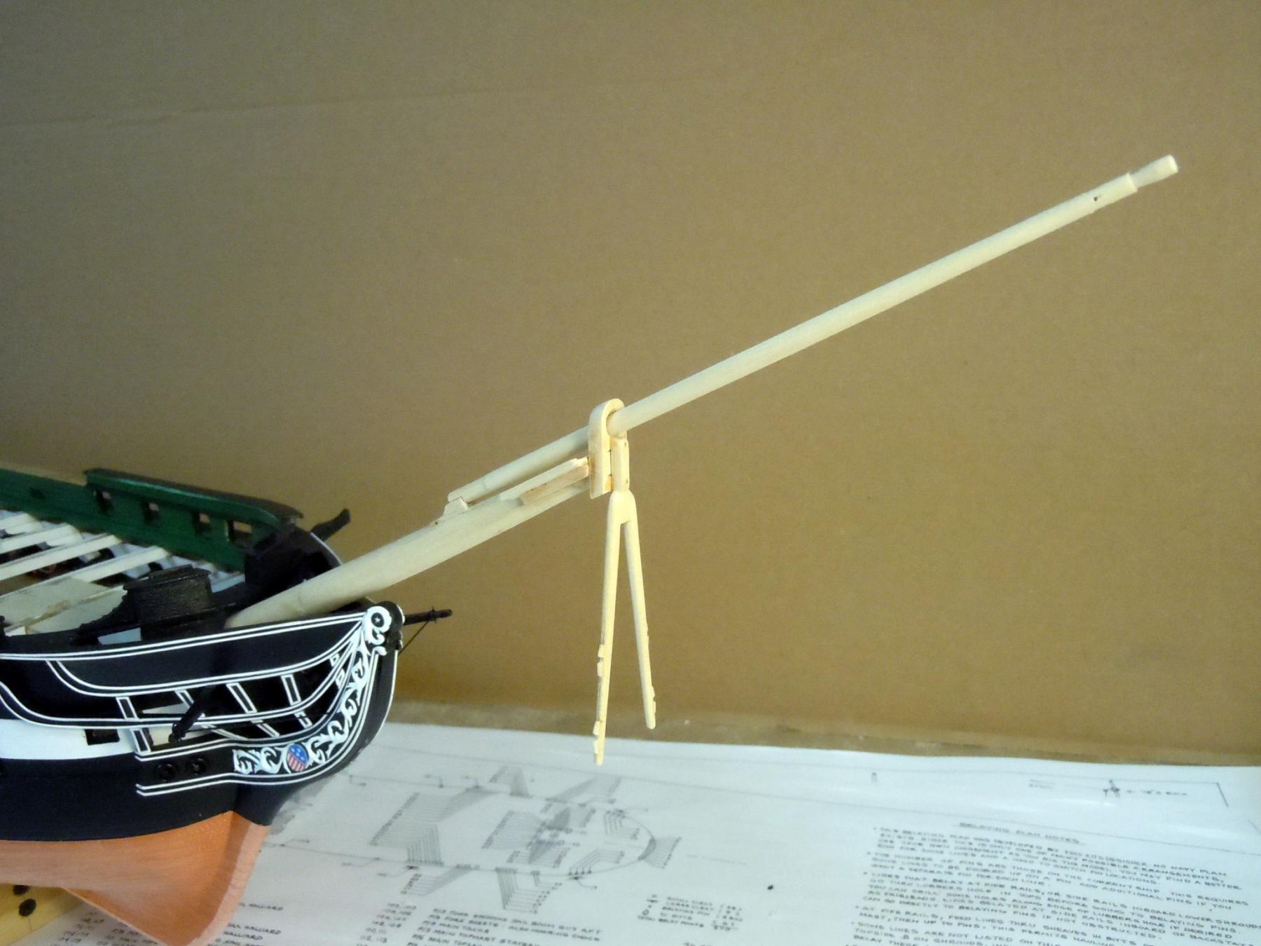
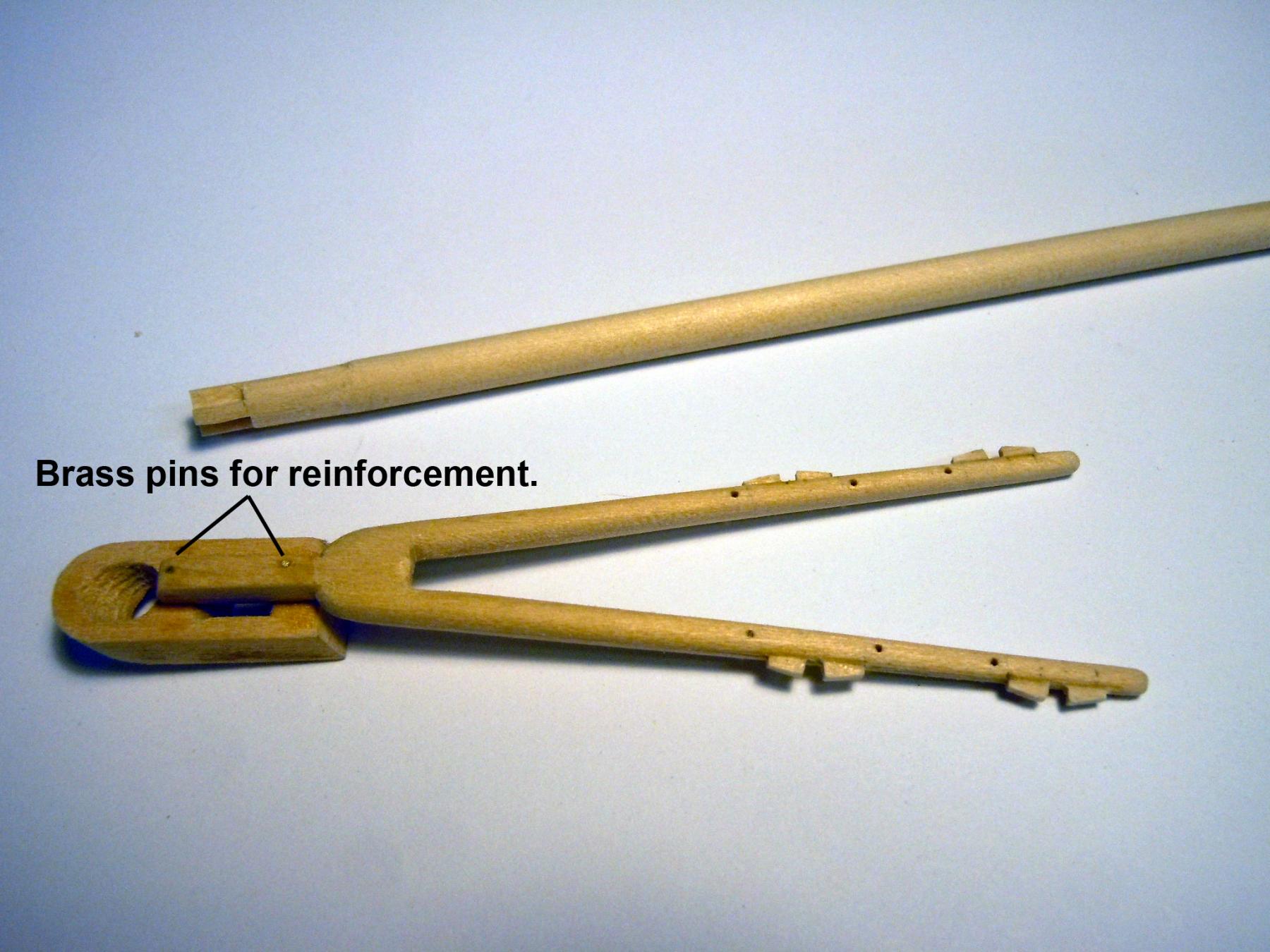
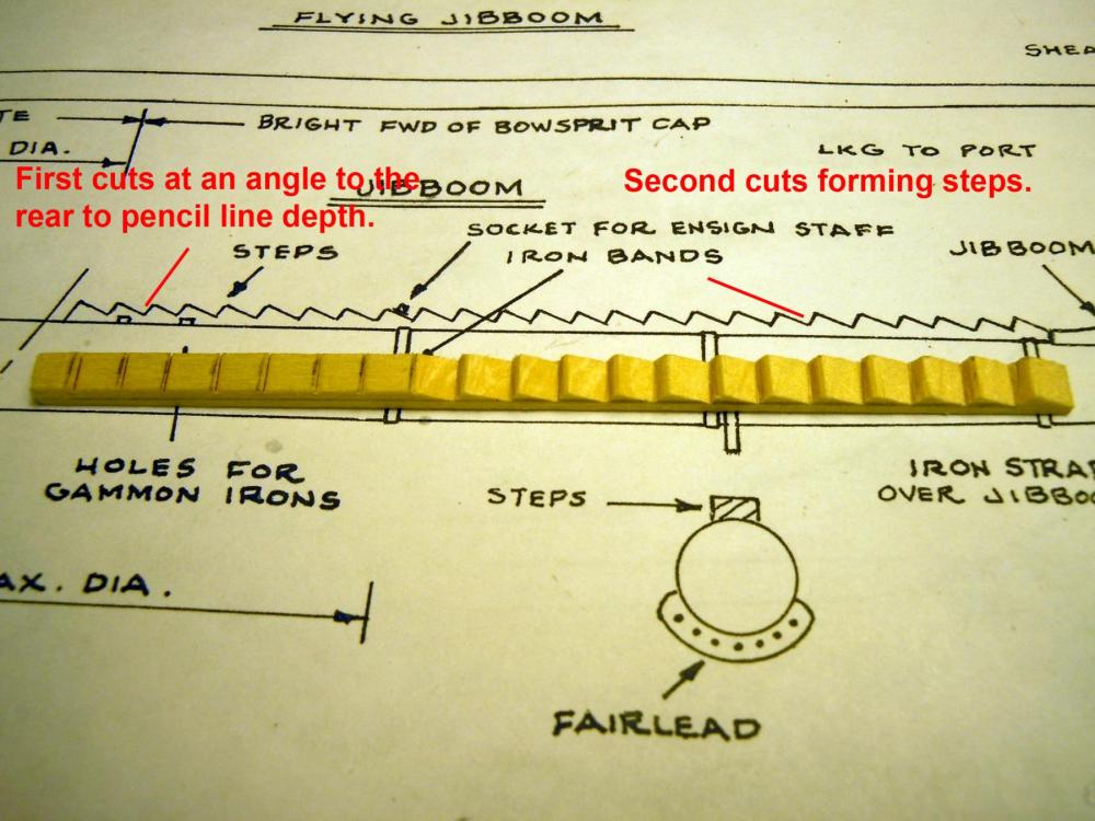
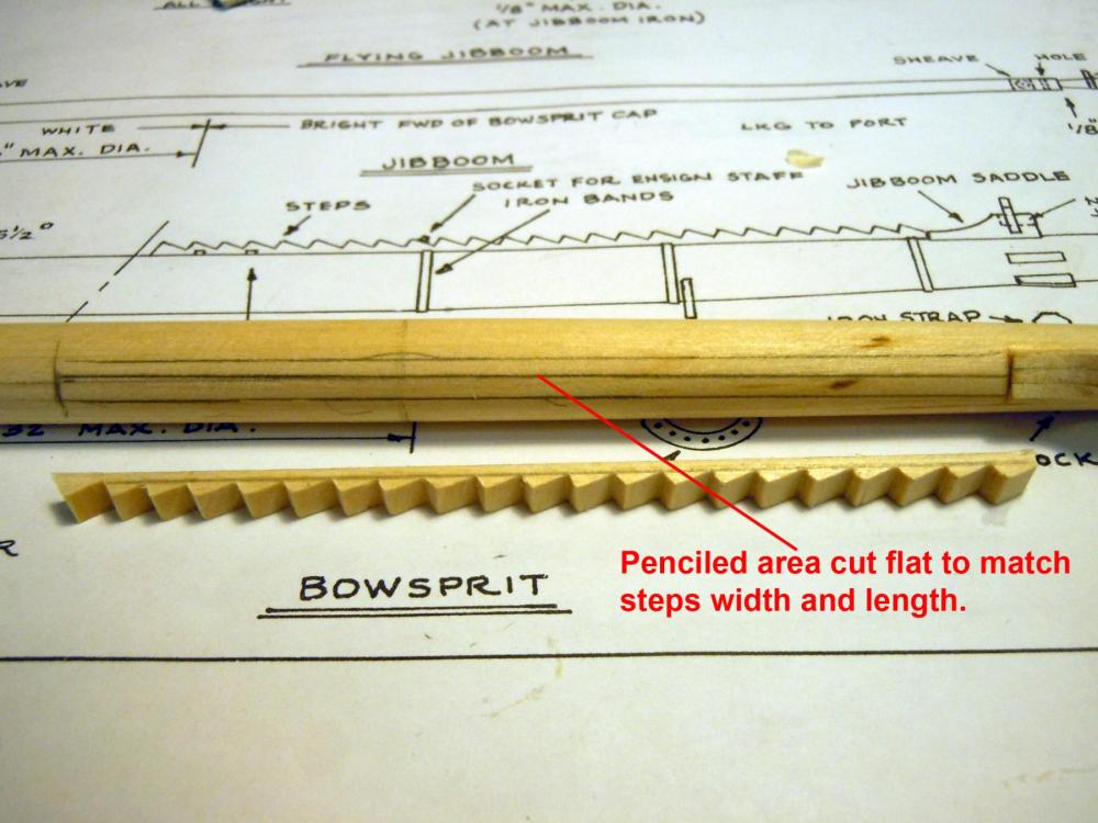
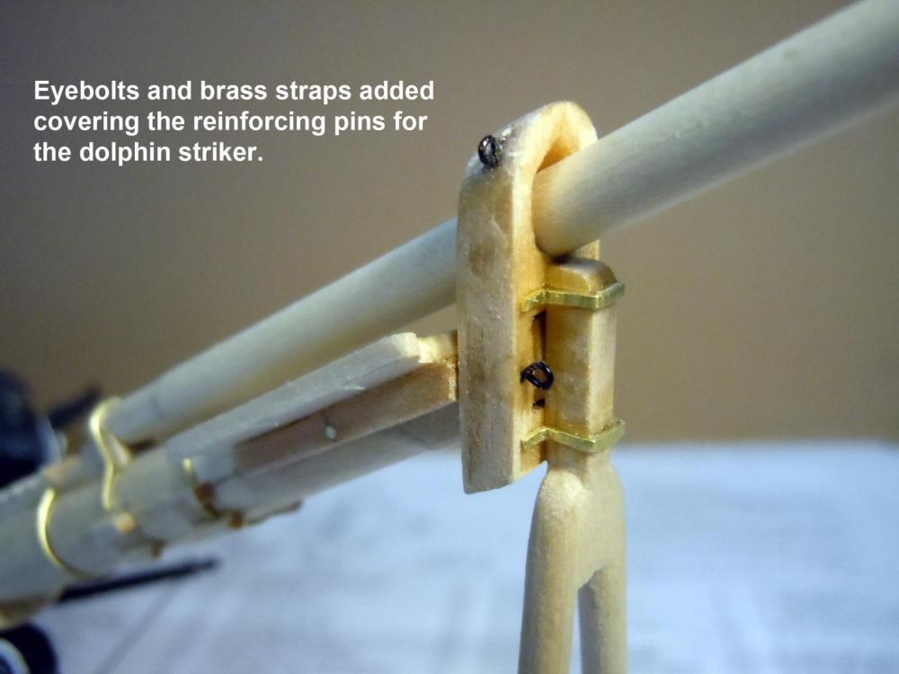
Finished up all the details on the bowsprit and then made both the jib boom and flying boom. Johnathan the bowsprit is removable and the dolphin striker is stronger than it appears but yes; better to be safe than sorry. Here is a sequence showing the finished up parts ready for paint and to be set aside. Approval was received for the laundry room rough in so insulation is now happening and I am on stand by for dry walling. My next direction will be to button up the gun deck and then start on the spar deck.


-
Matt, here is a source for tiny rivets of excellent quality that would be best for your efforts. I have used these on scratch builds and are great to work with but very tiny on the small sizes. Remember ancient proverb ..." You get what you pay for!" http://www.scalehardware.com/miniature-rivets-c-10 Here is another source that may be more cost effective and shorter, only 1/8" long. http://cir-kitconcepts.com/shop/index.php?main_page=product_info&cPath=12&products_id=162 Great job and looking forward to see the results.
- 117 replies
-
- 5
-
-
- constitution
- model shipways
- (and 1 more)
-
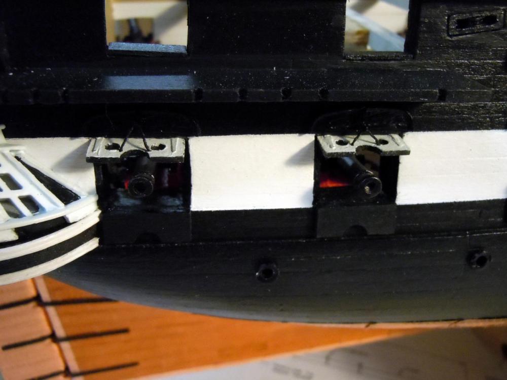
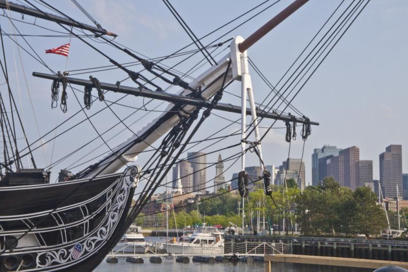
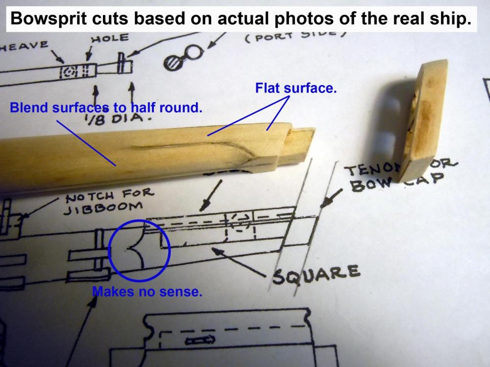
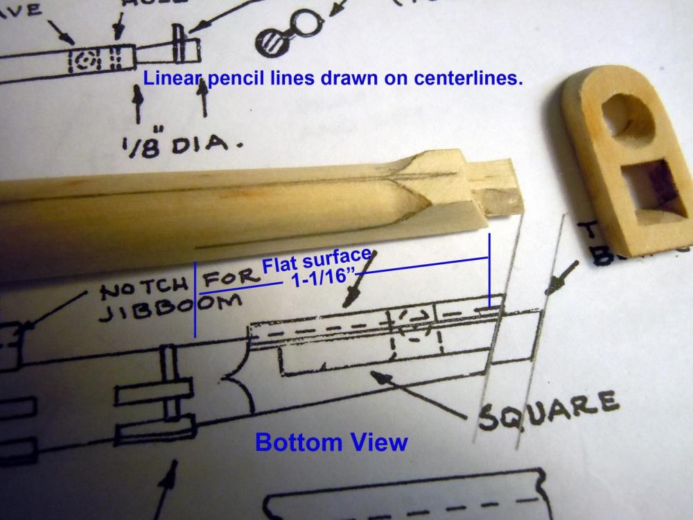
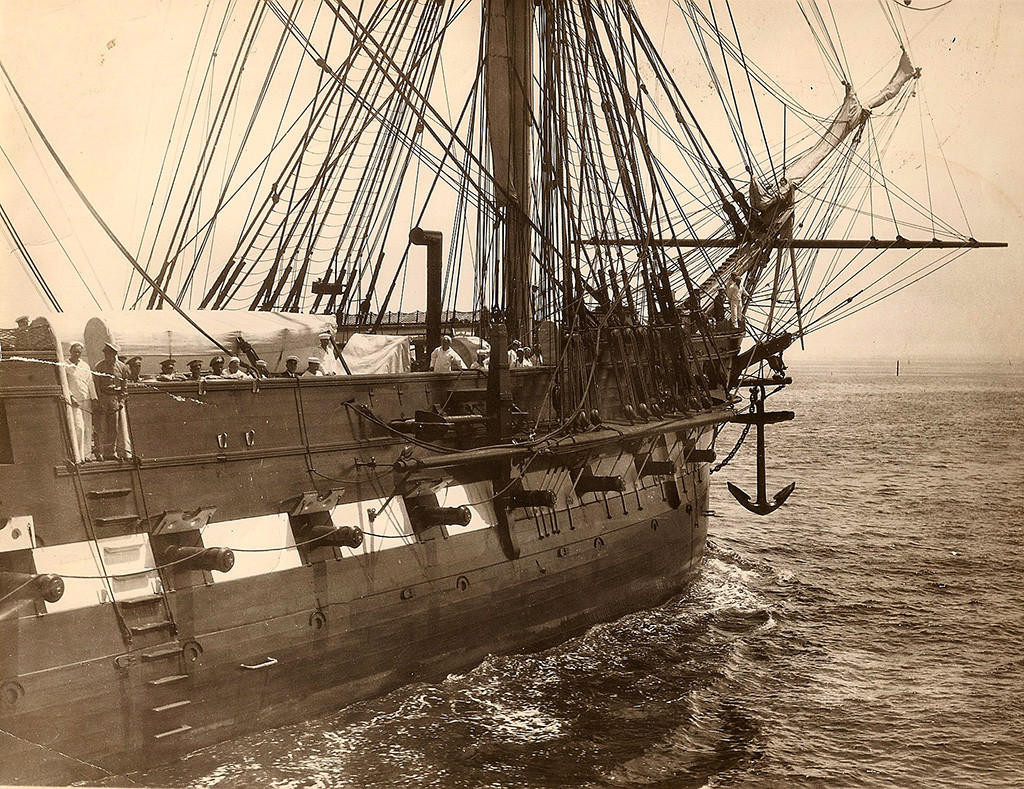
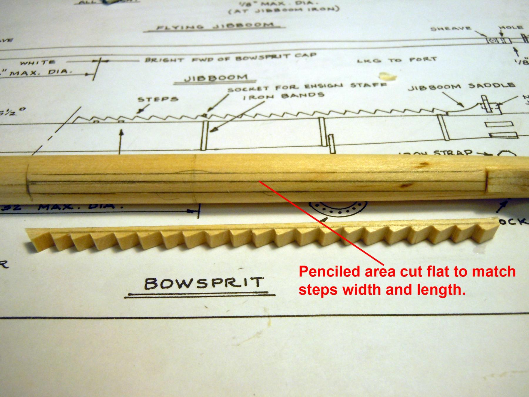
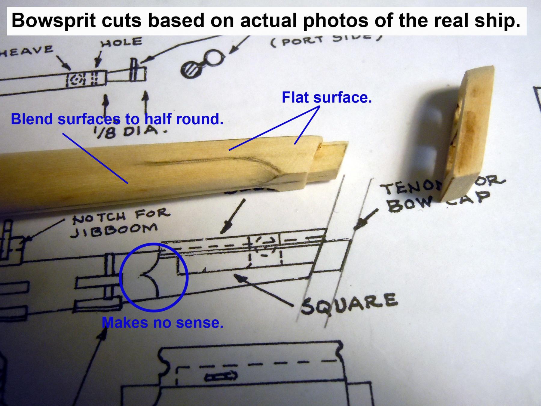
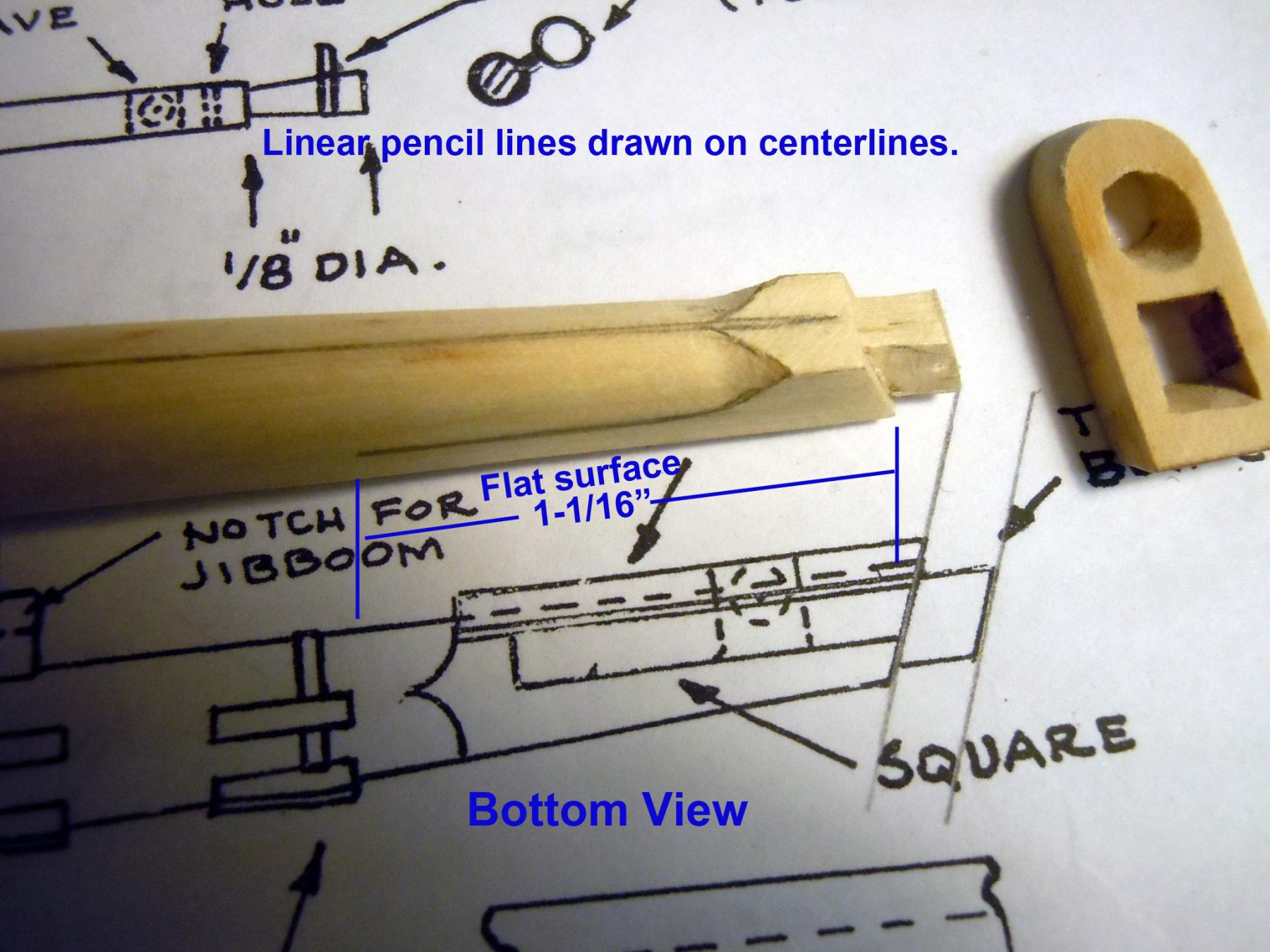
Jonathan, my remark was more of a comment rather than a complaint since the Niagara kit has cast cleats the same size as those needed for these applications. The next time I carve cleats I will post some pictures of the process. I have been working with the kids on their house renovation and drywall patching the existing living room ceiling and walls after walls were removed. Great exercise! I have some time to do some building and added the gunport carved decorations to the top of all the gunports as well as the lower covers. I then did a test for the top covers and decided that these will wait until the spar deck is installed so as not to damage them. I am trying to button up all the steps needed before adding the spar deck. The carved decorations needed the drilled holes for the lines which would cause wood bits on the gun deck which are easily cleaned without the spar deck in place. I also realized that it might be wise to index the bowsprit in place as well which required fabricating the bowsprit. In reviewing the plans I noticed that a drawn detail did not make sense given the blending of flat surfaces and round ones; so back to actual photos of the real ship, one can be seen below. Here are a couple of pictures of how I resolved the issue based on the photos. The main tapering of the bowsprit fore and aft then followed the plans; but the end did not. I then got carried away and fabricated the dolphin striker as well. Another opportunity to hone my wood carving skills which are getting better everyday. Here are the in progress parts coming together with more details yet to be added. Now back to adding more bowsprit details. We are waiting for the city inspection on the electrical and plumbing of the new laundry room before I can get back to dry walling.