HOLIDAY DONATION DRIVE - SUPPORT MSW - DO YOUR PART TO KEEP THIS GREAT FORUM GOING! (Only 24 donations so far out of 49,000 members - C'mon guys!)
×


xken
-
Posts
841 -
Joined
-
Last visited
Content Type
Profiles
Forums
Gallery
Events
Everything posted by xken
-
 Steve, years of model building, but just my second ship and still learning a great deal.
 -
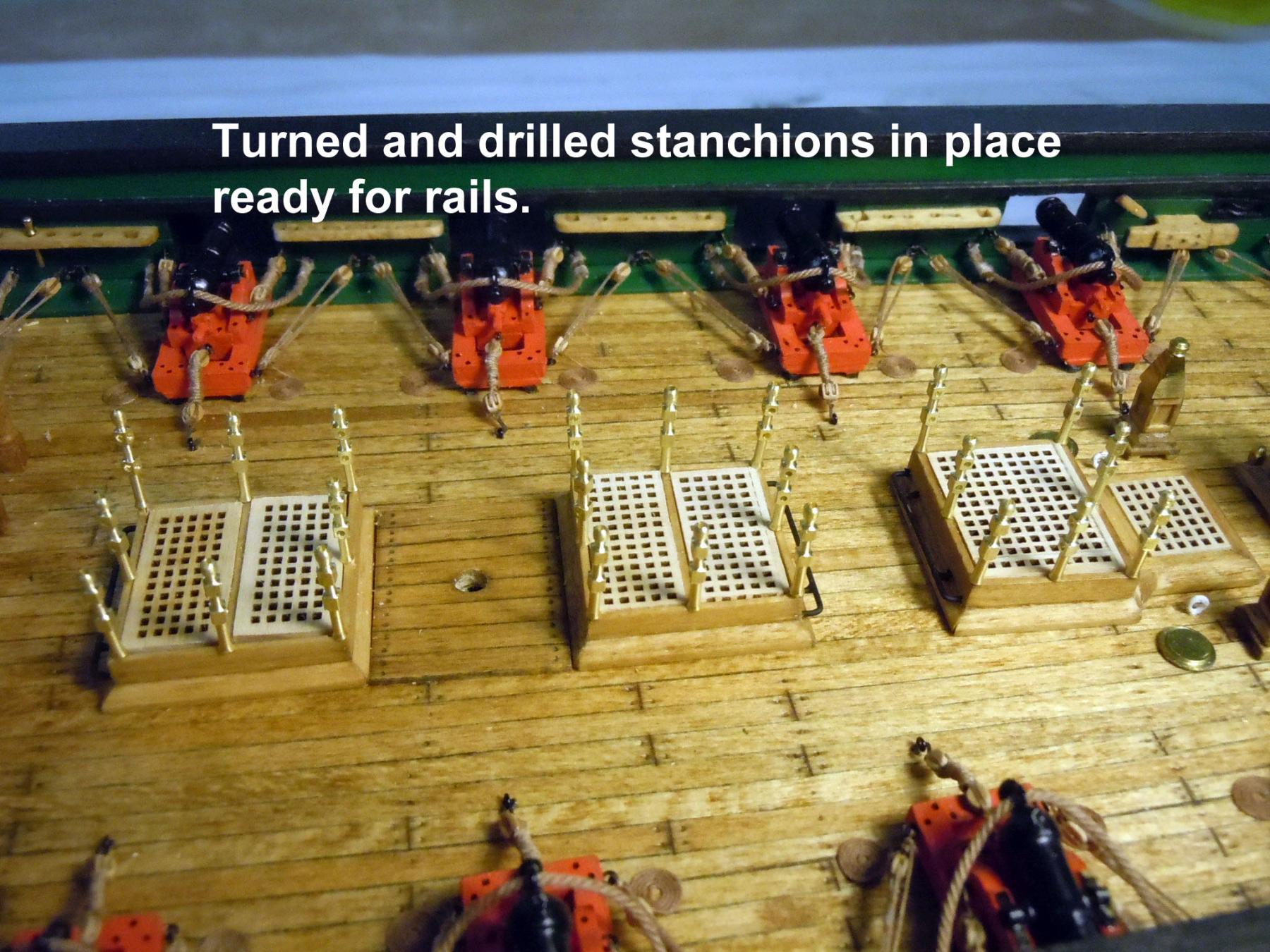
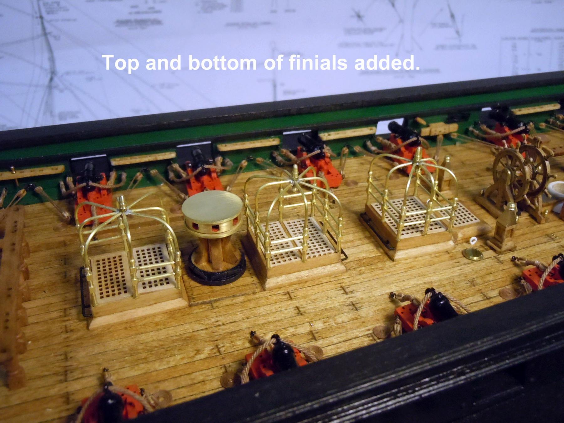
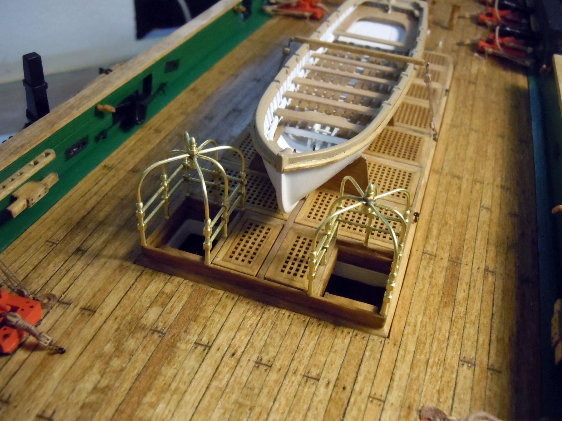
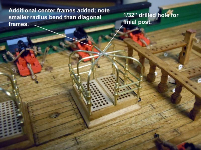
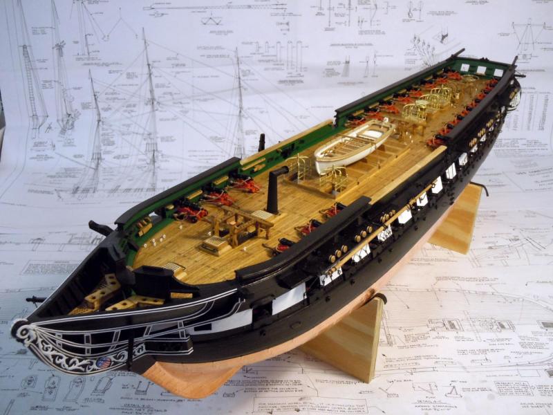
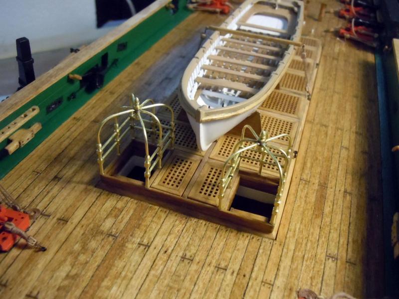
Back from the NRG Conference and I think my presentation was well received as well as participation in the round tables. I had a chance to meet and see the work of many great ship builders and sold out of the books I took for sale. Getting back to work I continued on the canopy frames for the aft hatches and turned many stanchions, as well as, drilling them for their appropriate positions. Following is a series of pictures showing them being fabricated much as the same as the forward ones were made; of course no two were the same configuration. An overview of the hull so far. Next I will add the step plates on the deck and frames as needed and then onto the masts.


-
Tool for Shaping Brass Strip
xken replied to mikiek's topic in Metal Work, Soldering and Metal Fittings
Visit this supplier for a great selection of brass stock. They have both formed (rounded edges) and extruded (square edges) U profiles. Plan ahead they do have a $20 minimum order amount. http://www.specialshapes.com/ -
Here is a great source I have used to buy in gross (144) amounts brass nuts, bolts and washers. Explore their site for other hardware selections and tools. http://jimorrisco.com/index.php
-
Zoltan, I am not sure if there is a location to upload reference images. But if you have a particular area or detail please let me know and I can post them on your Santa Maria build. I notice that your ship has many similarities to this one. Let me know what you need.
-
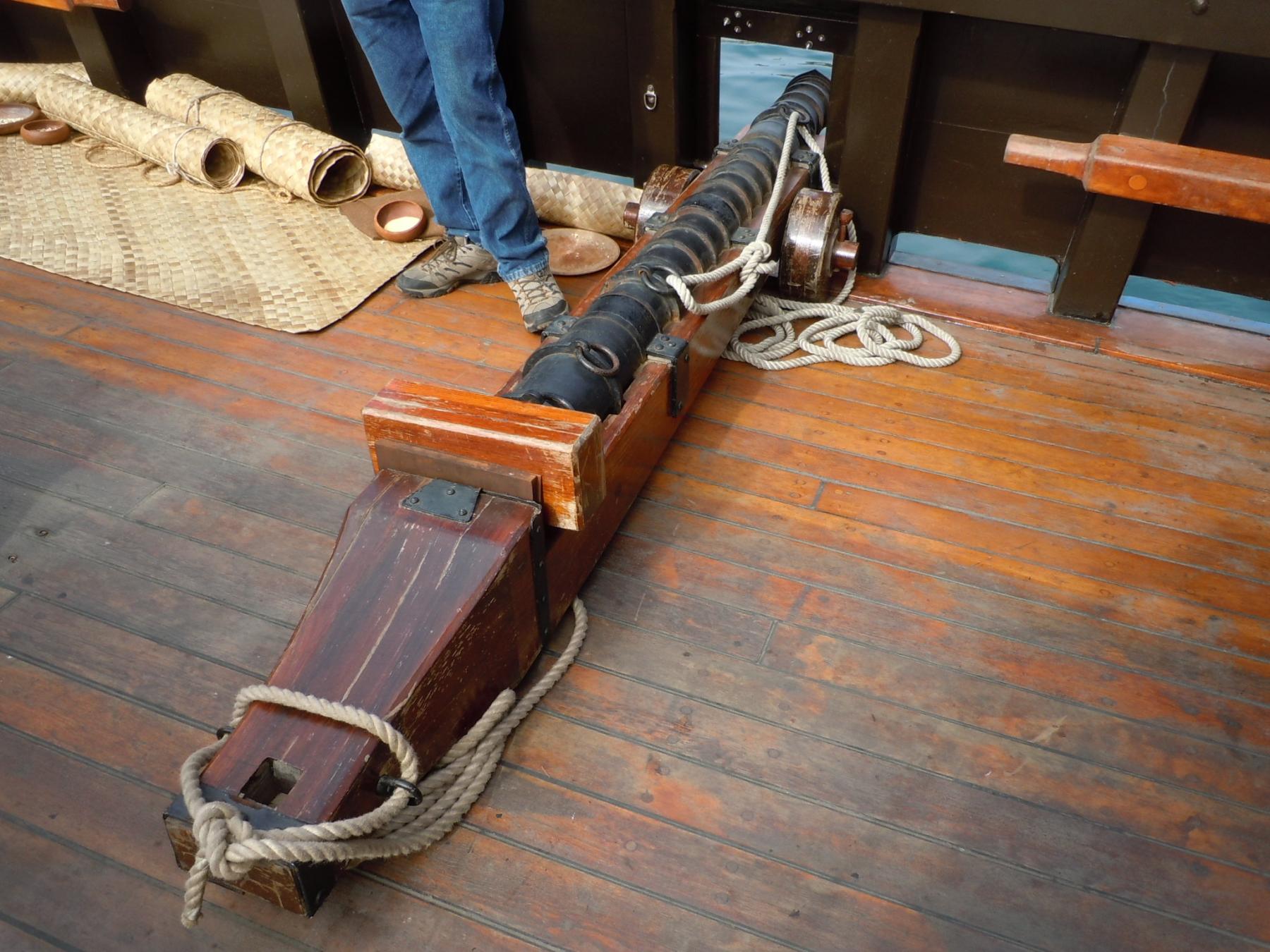
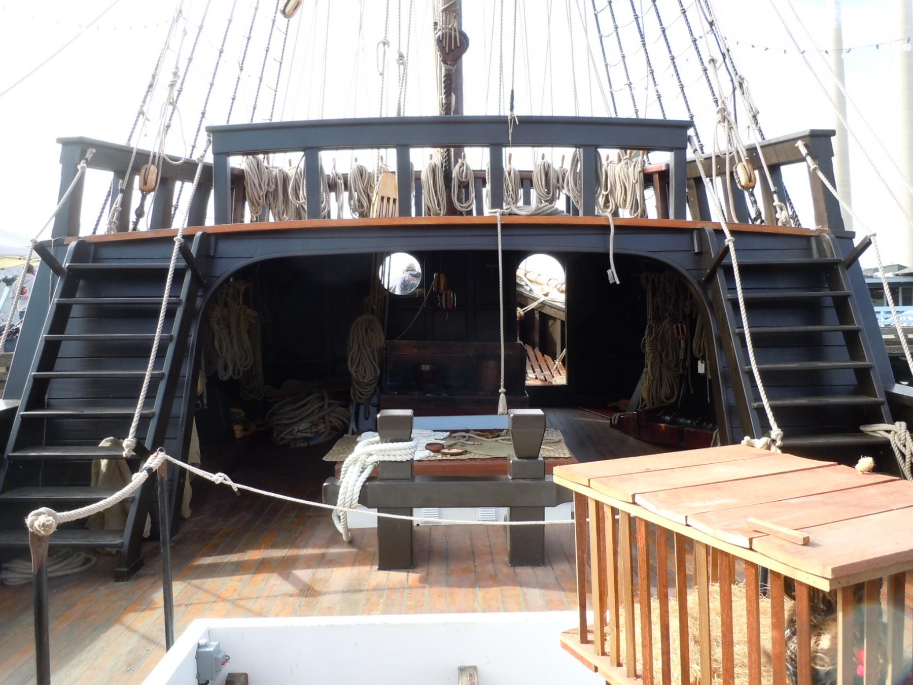
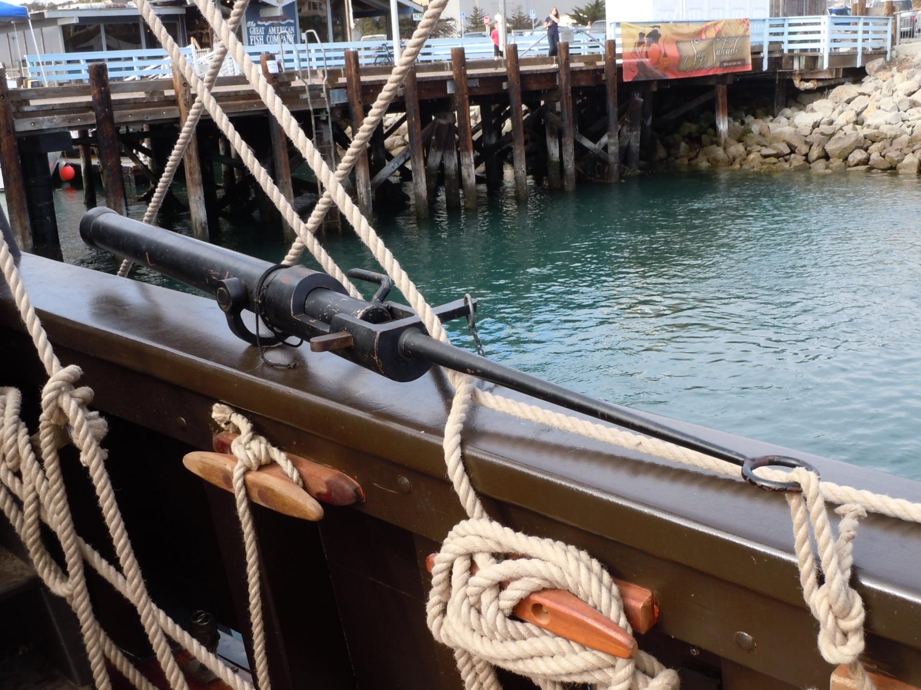
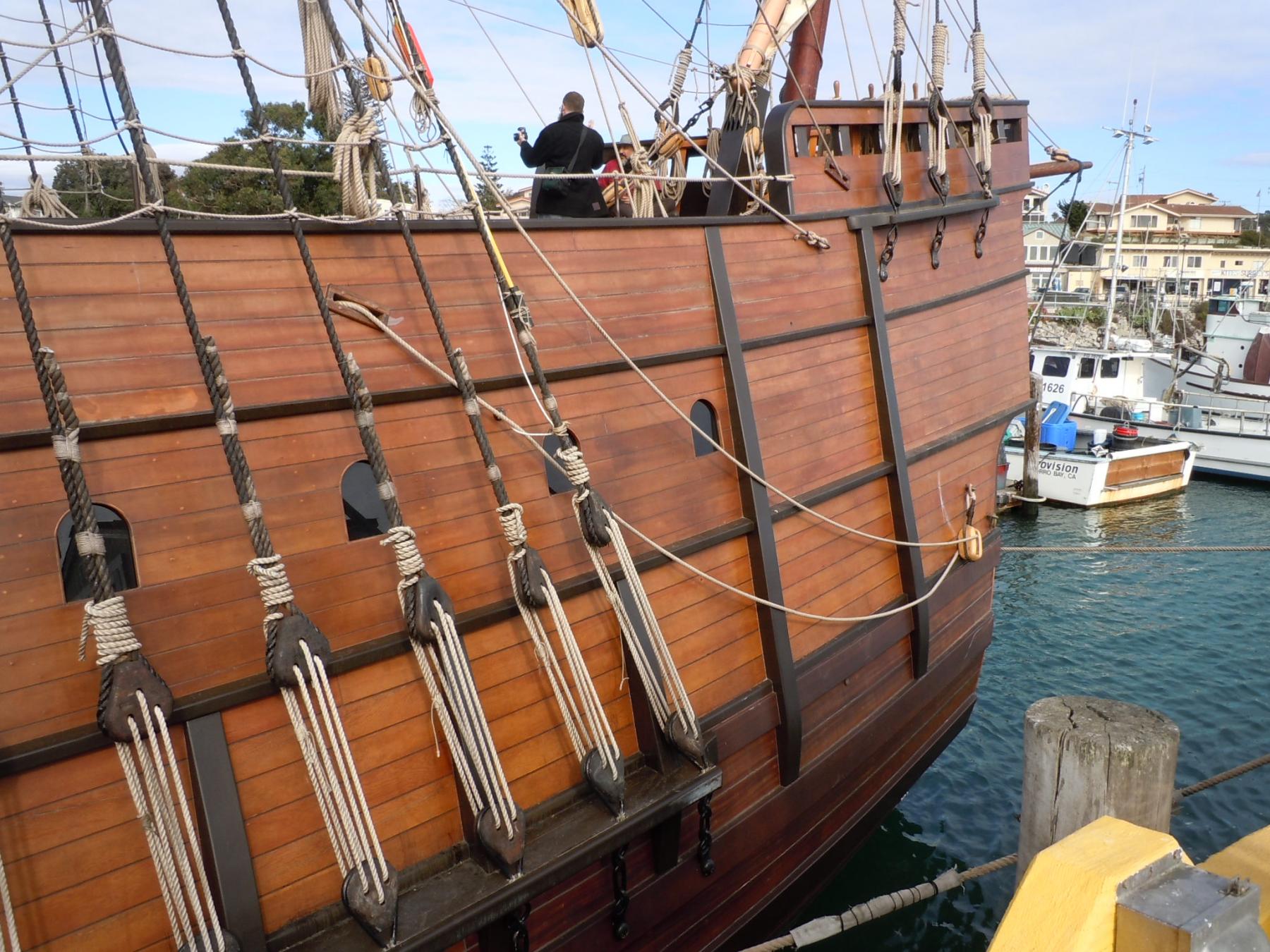
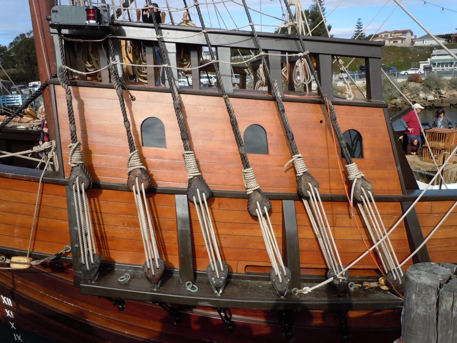
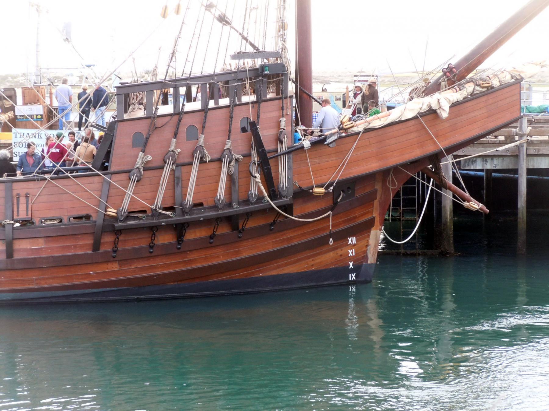
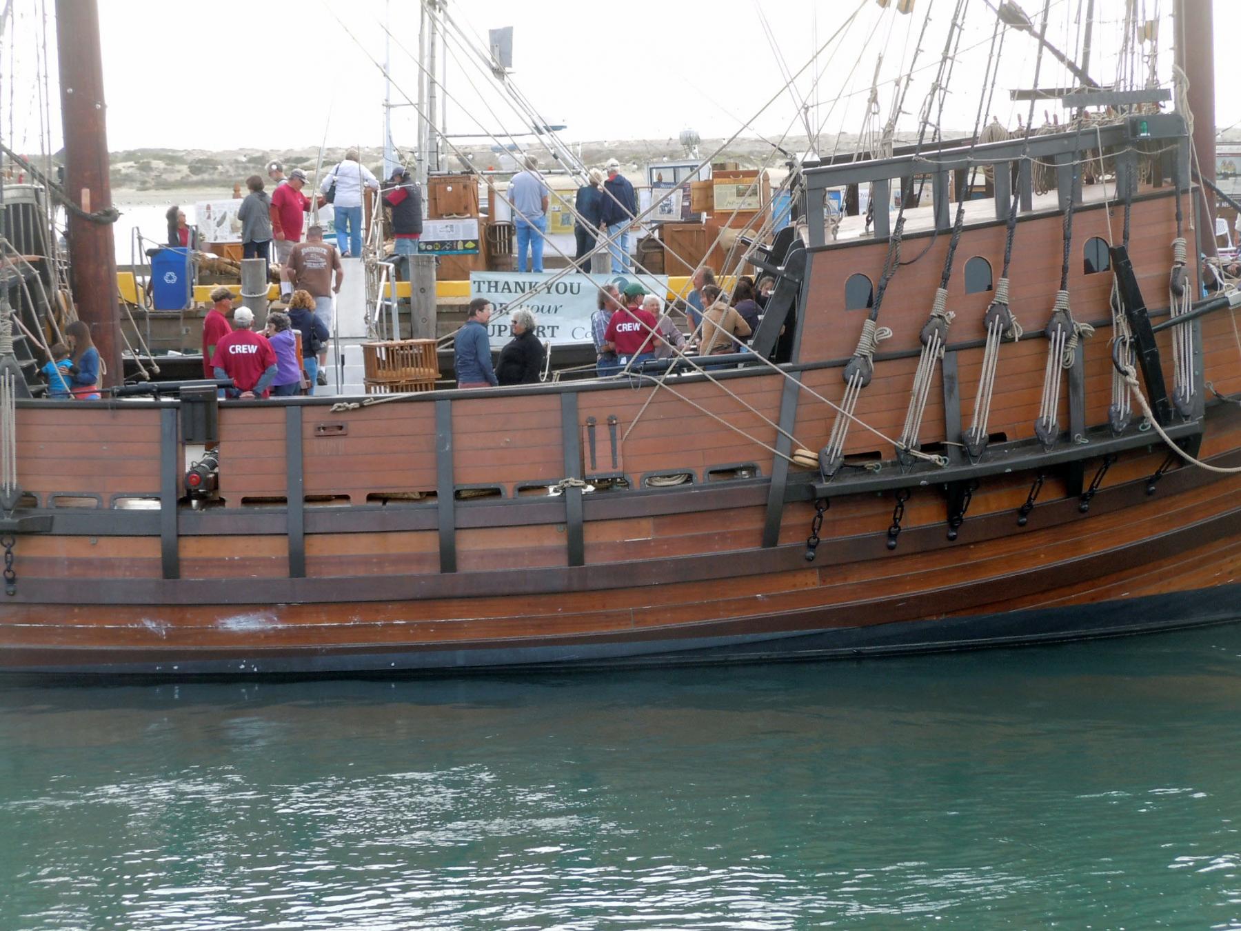
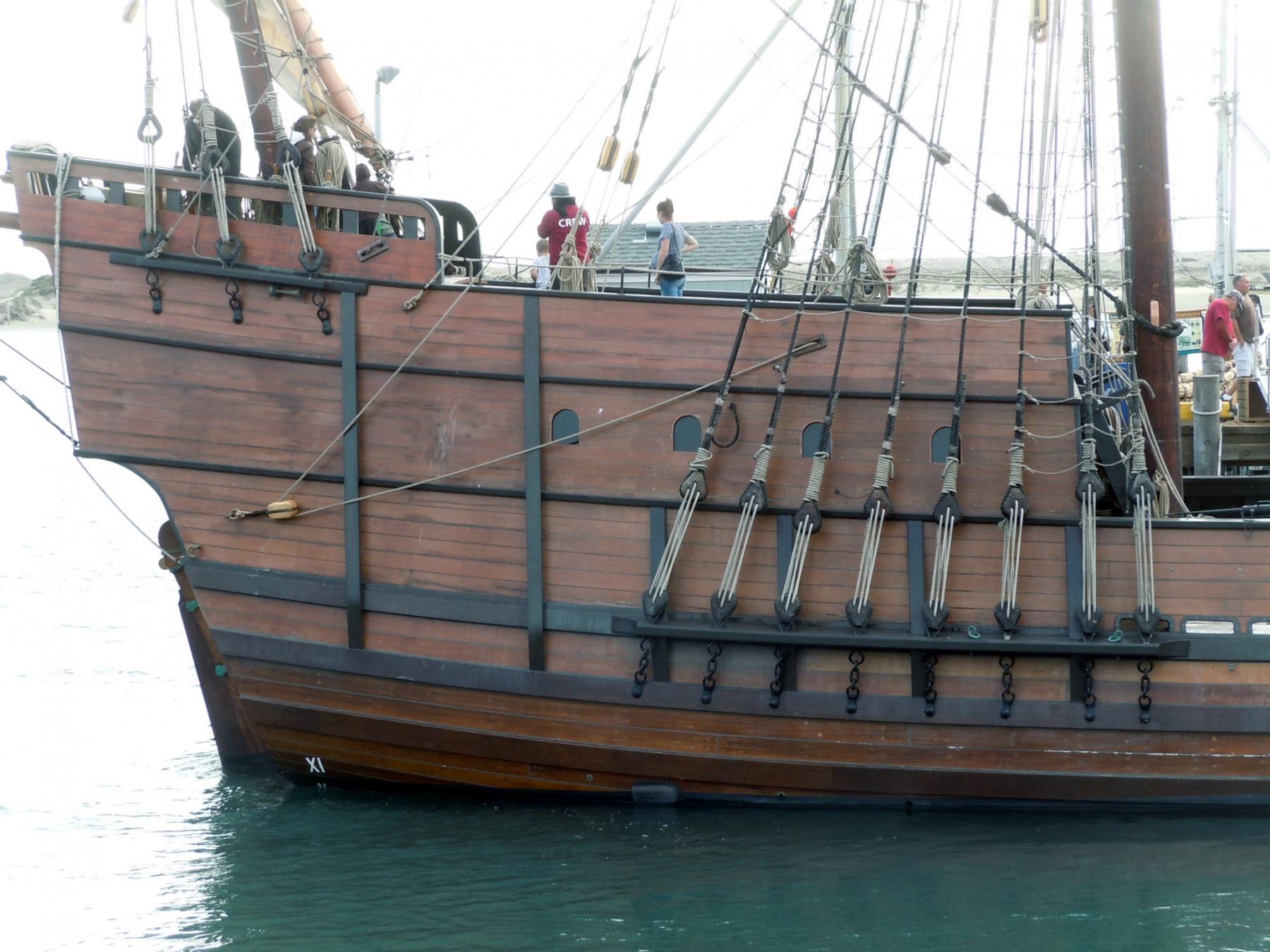
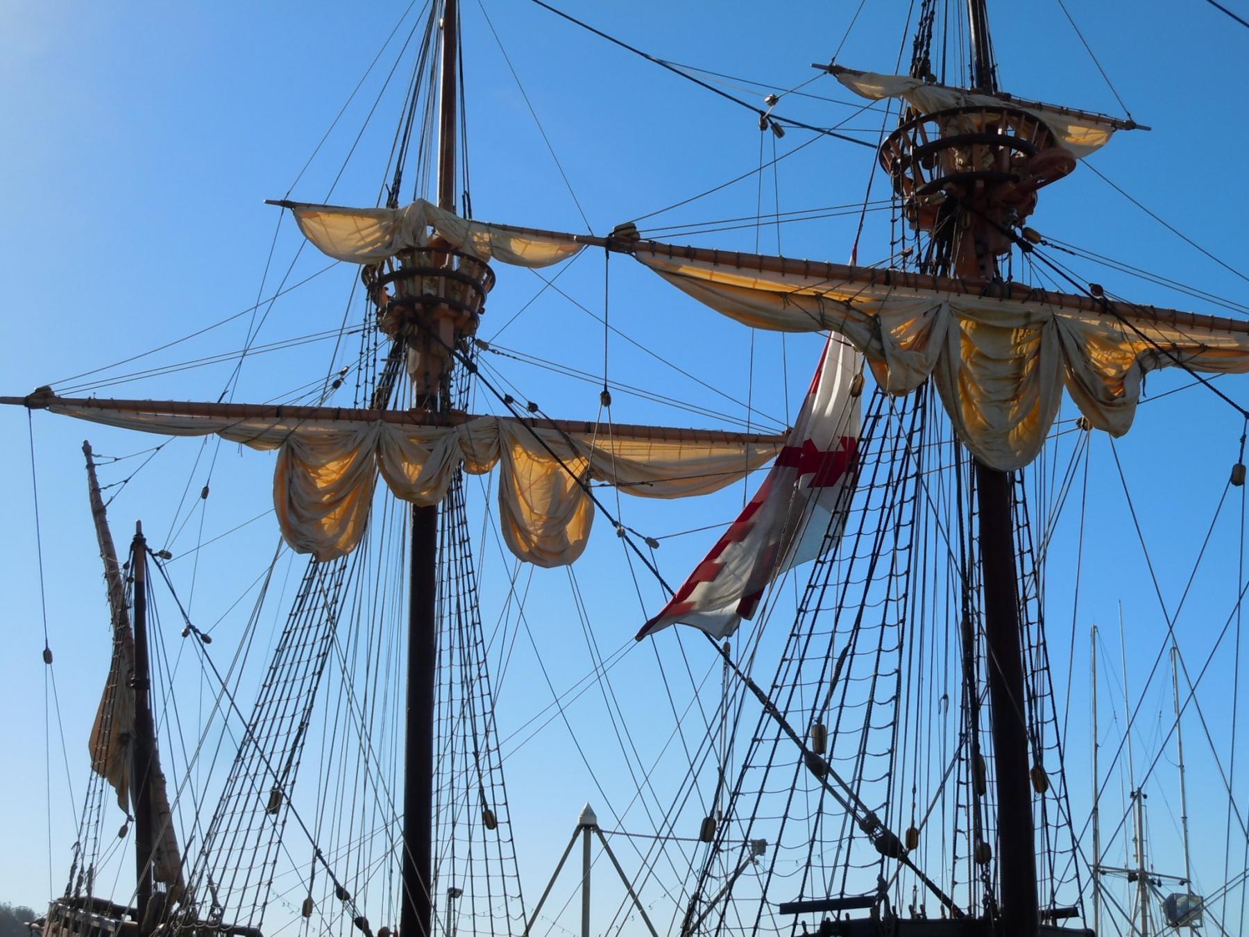
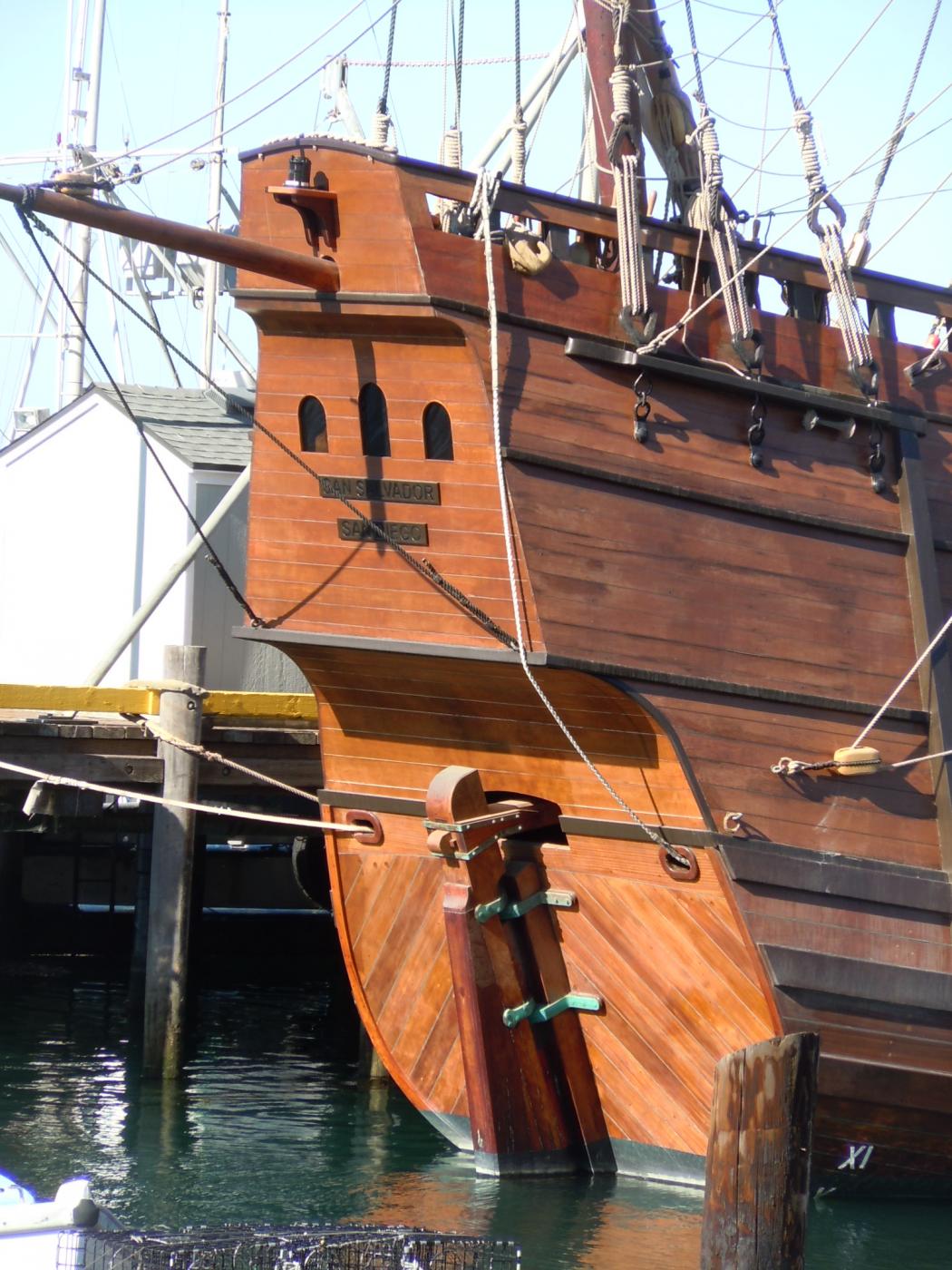
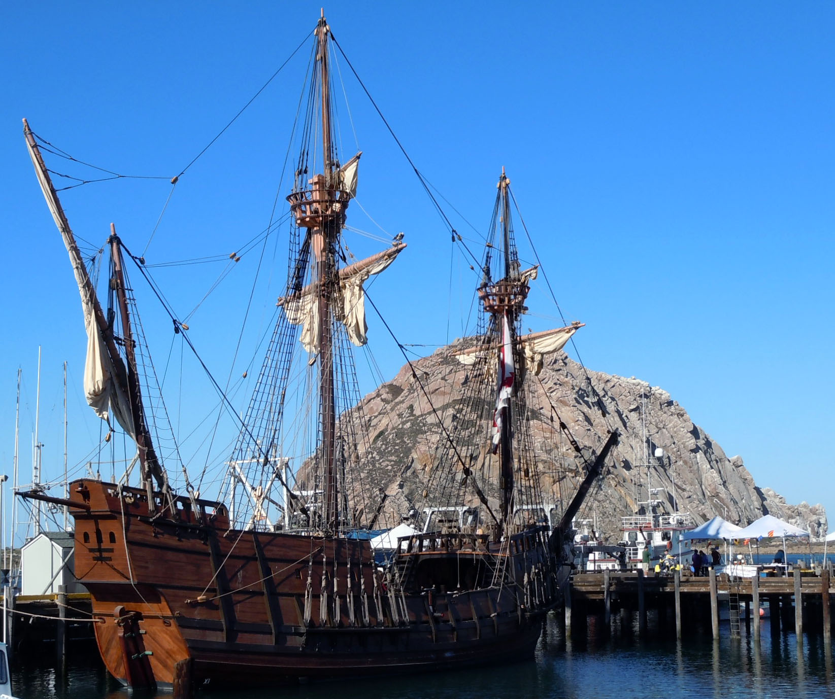
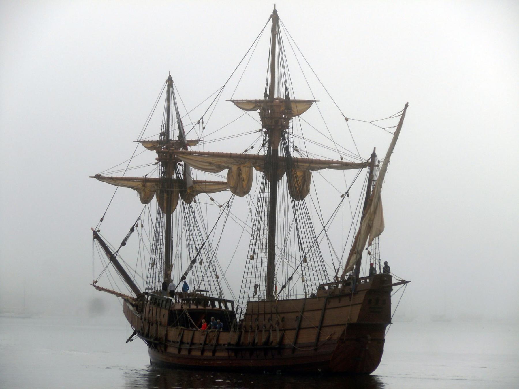
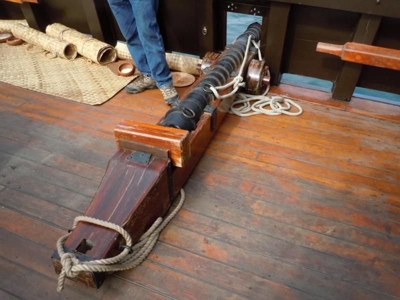
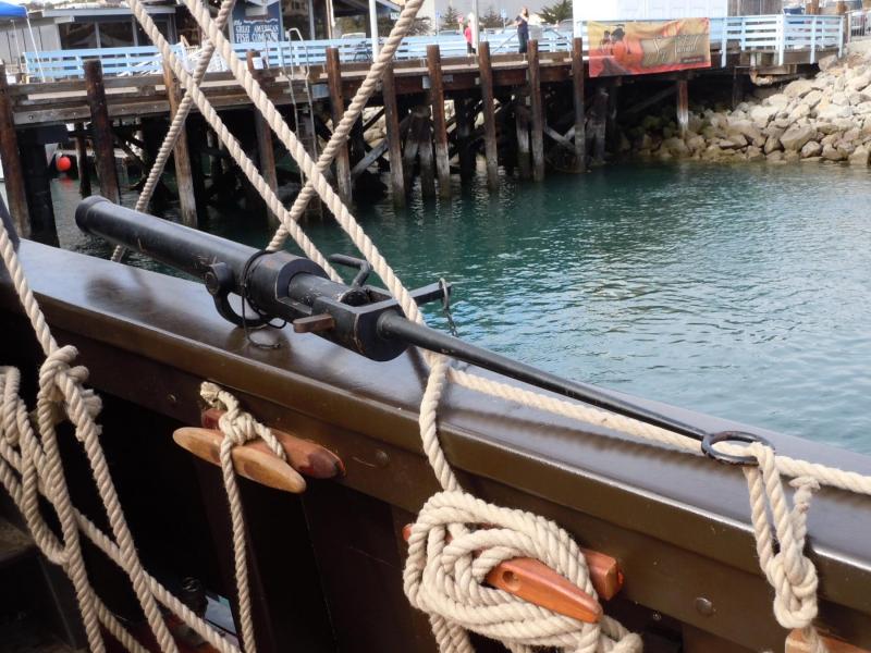
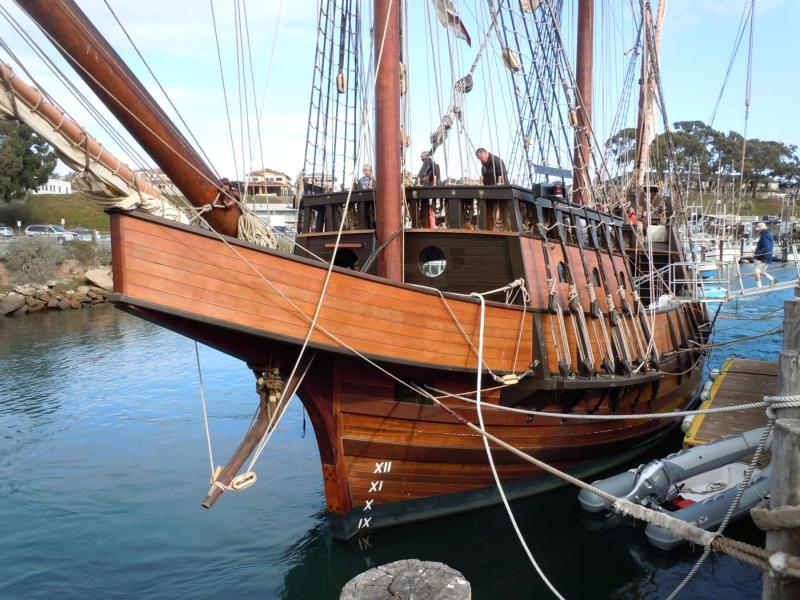
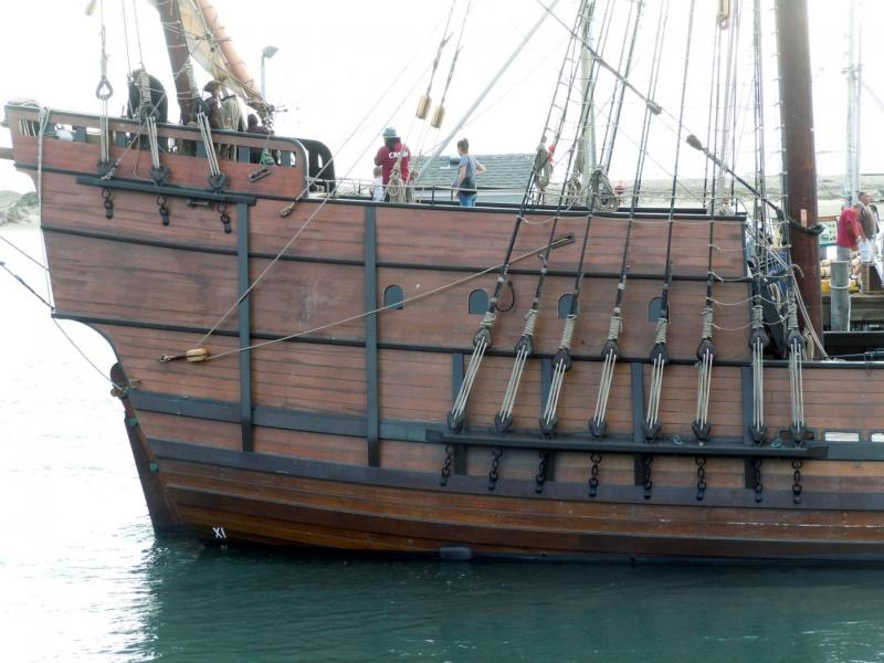
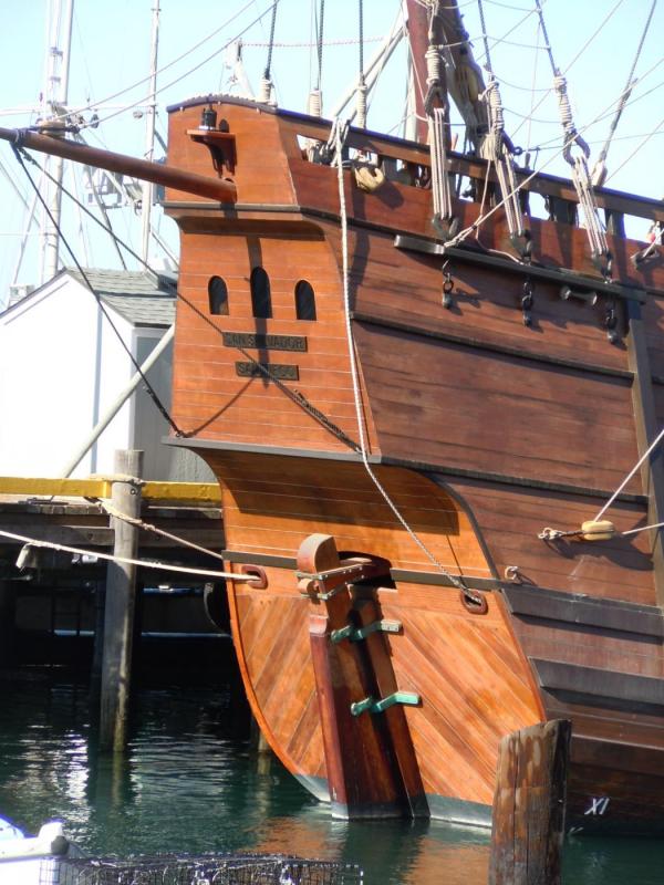
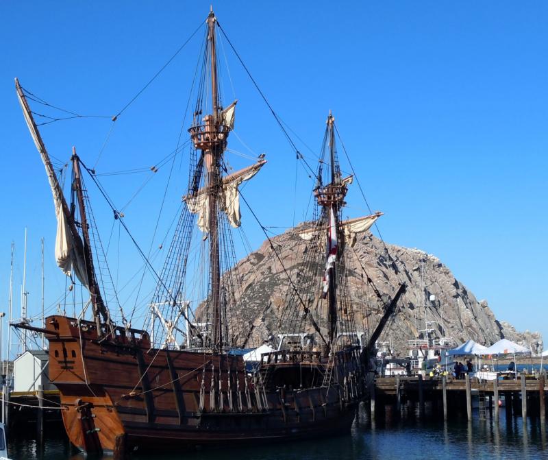
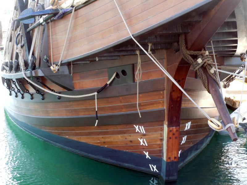
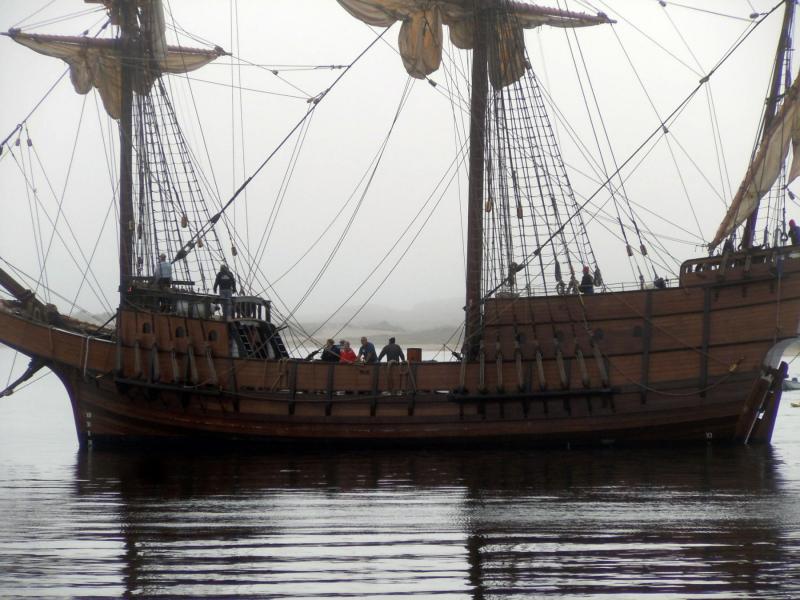
Getting packed up to head down to San Diego for the NRG Conference Thursday. In the meantime I have visited the San Salvador a couple of times and have taken over 300 reference photos like these random samples. This could be a great scratch build subject. The only thing was that we were not allowed below deck into the hold area. Here is Morro Rock in the background. I live only 2 1/2 minutes from where she is docked in Morro Bay. his ship was suppose to be in San Diego during the conference time, but the schedule was moved forward for her Maiden voyage to up here.


-
I will need a bigger cart!
-
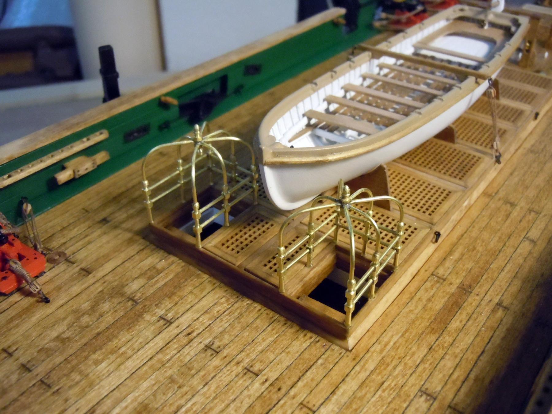
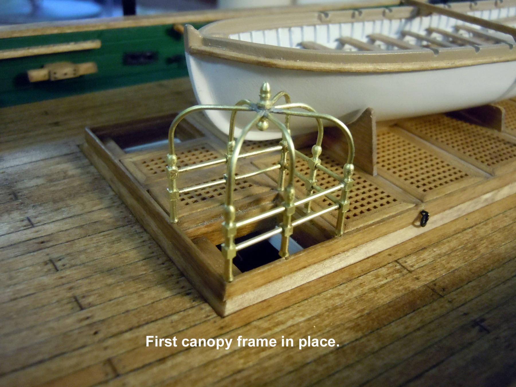
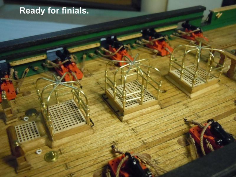
I now have the second frame completed and am getting the turning down pat for the stanchions and finials. I may now turn the balance of the stanchions for the rear hatches all at once. Here are a couple of pictures of the second canopy frame in place. They have been dipped into the JAX Instant Brass Cleaner for ongoing protection and luster. Back to work turning and weekend honey-do's.

-
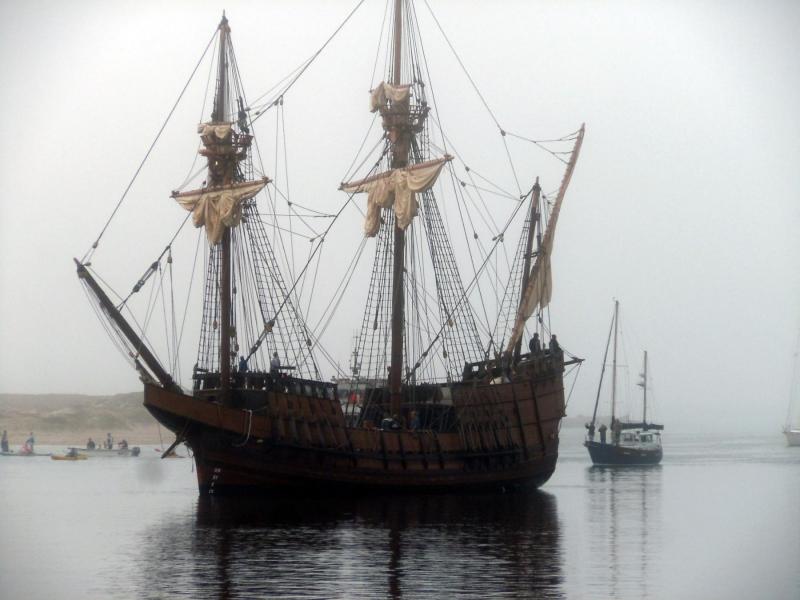
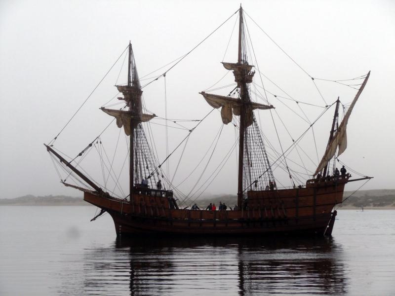
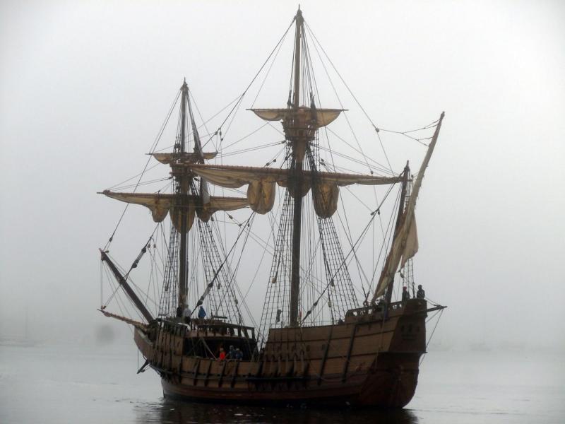
Kurt, yes it was great watching it emerge from the fog as it entered to mouth of the harbor. What was very interesting was seeing the muzzle flash radiate within the fog when it fired it's cannon salute just before it became visible. I plan on visiting and taking many reference photos while it is here. I will inquire to see if any plans are available for it.
-
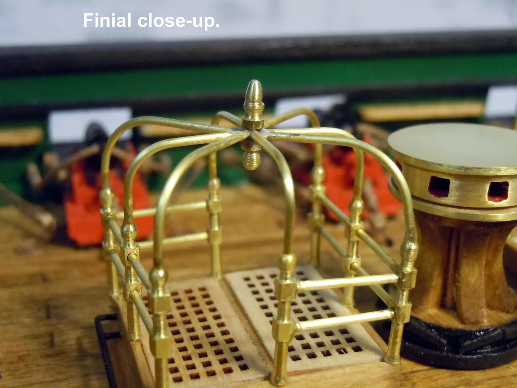
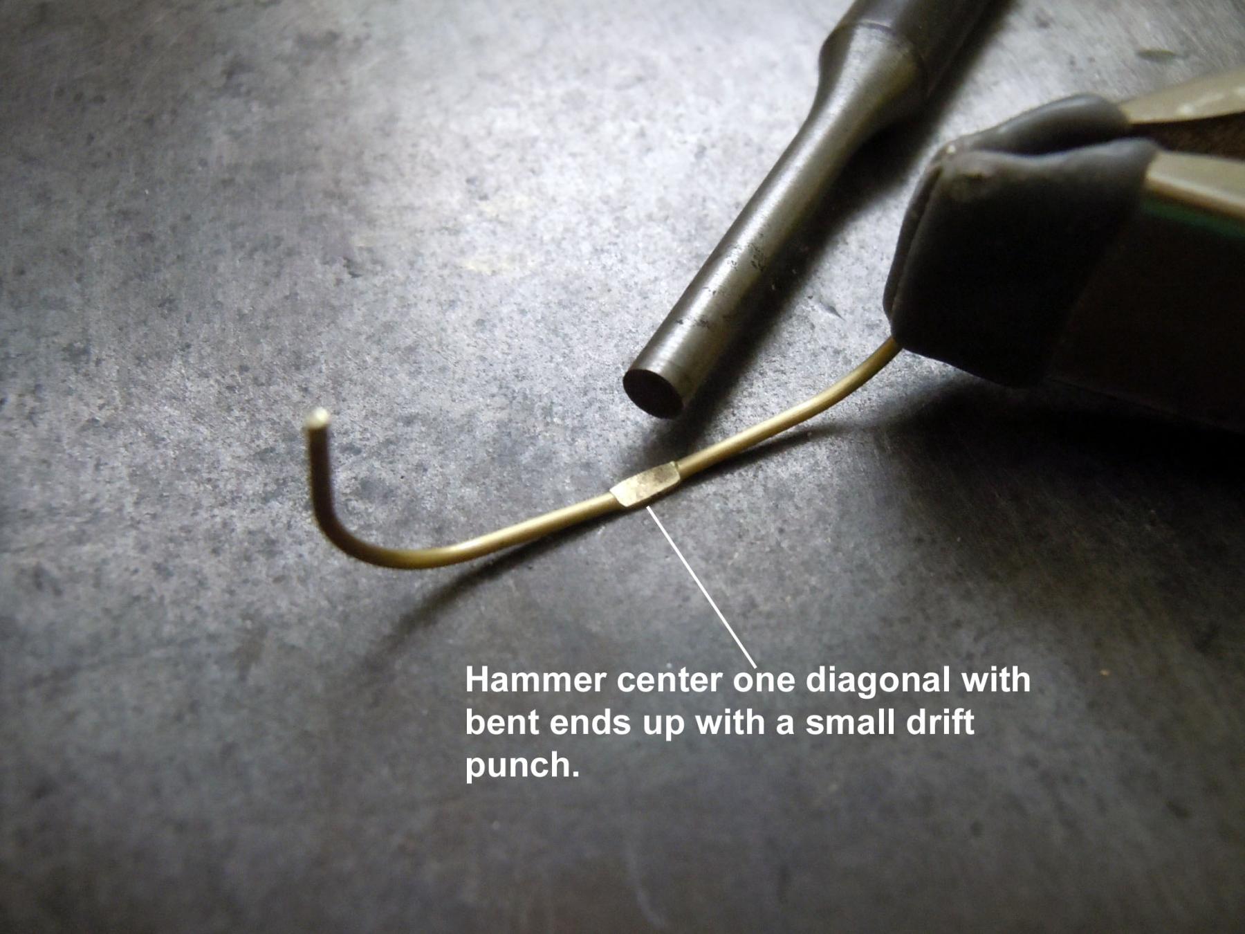
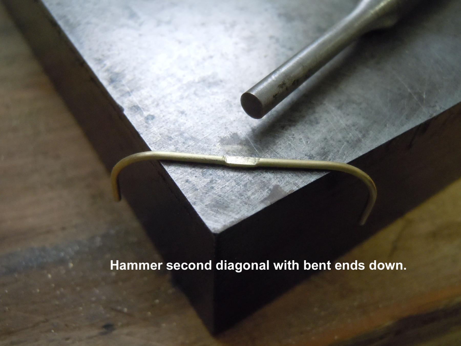
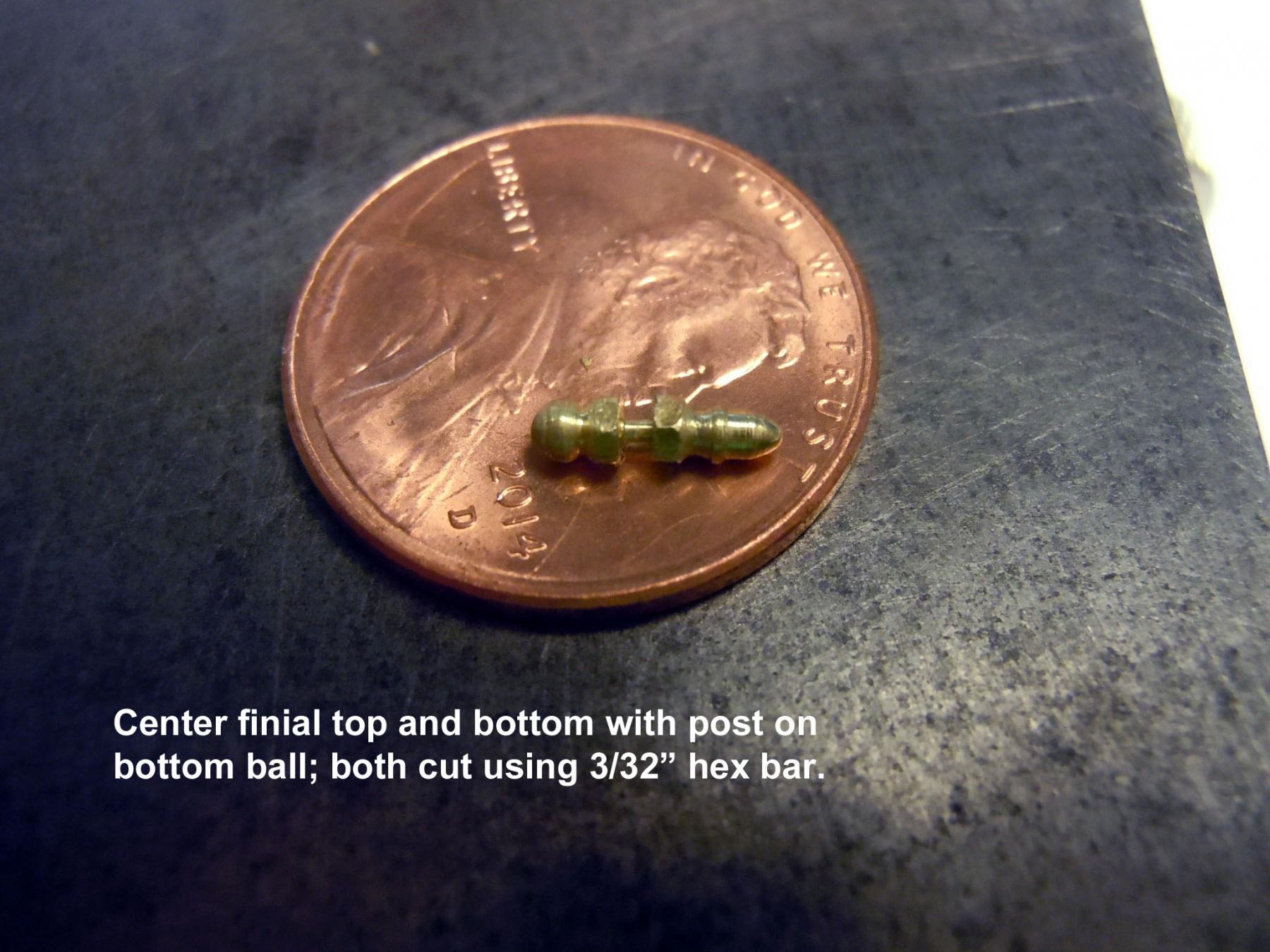
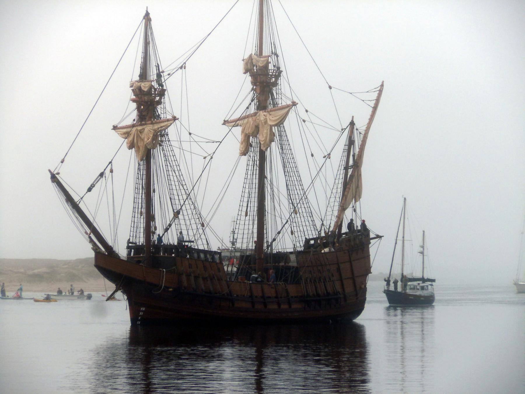
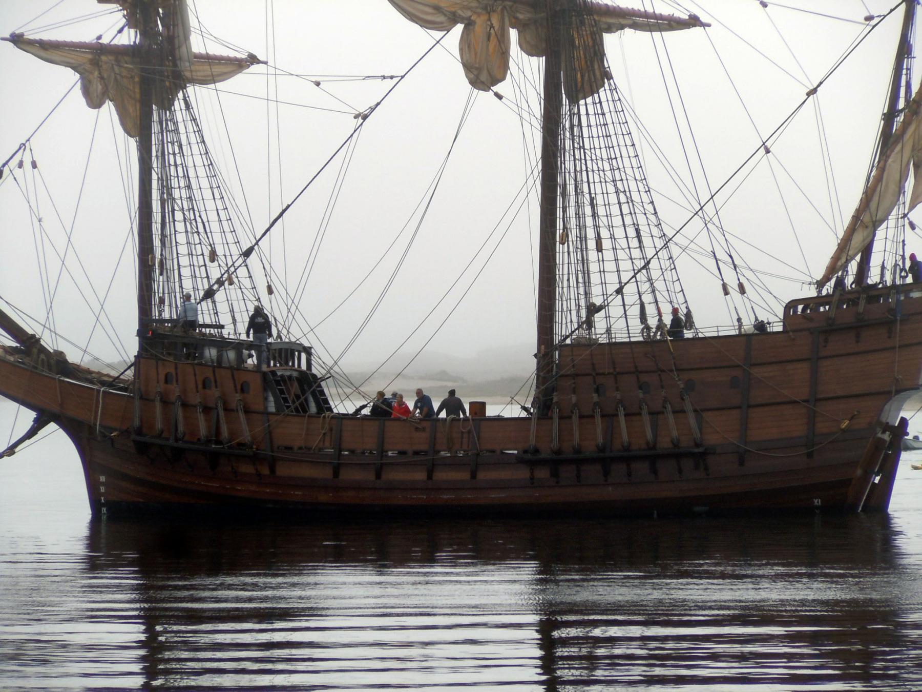
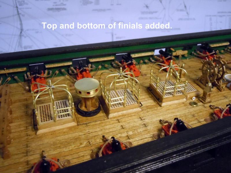
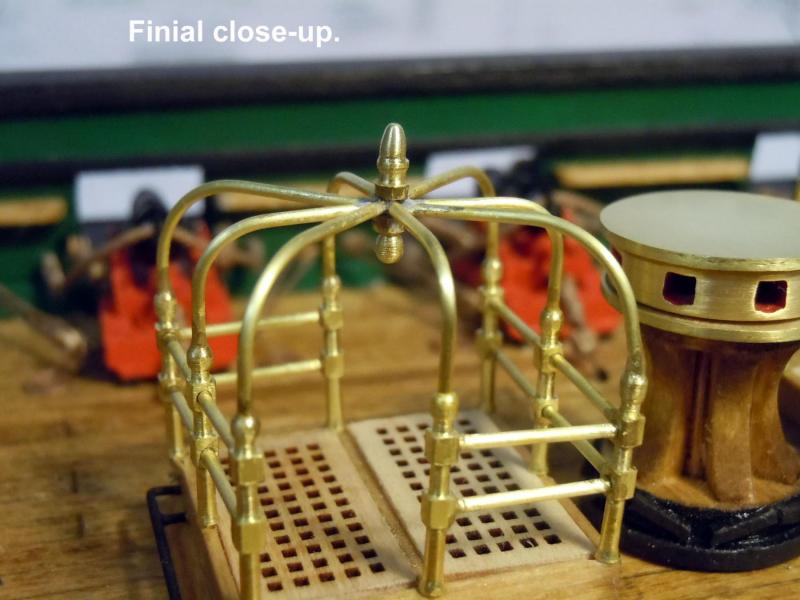
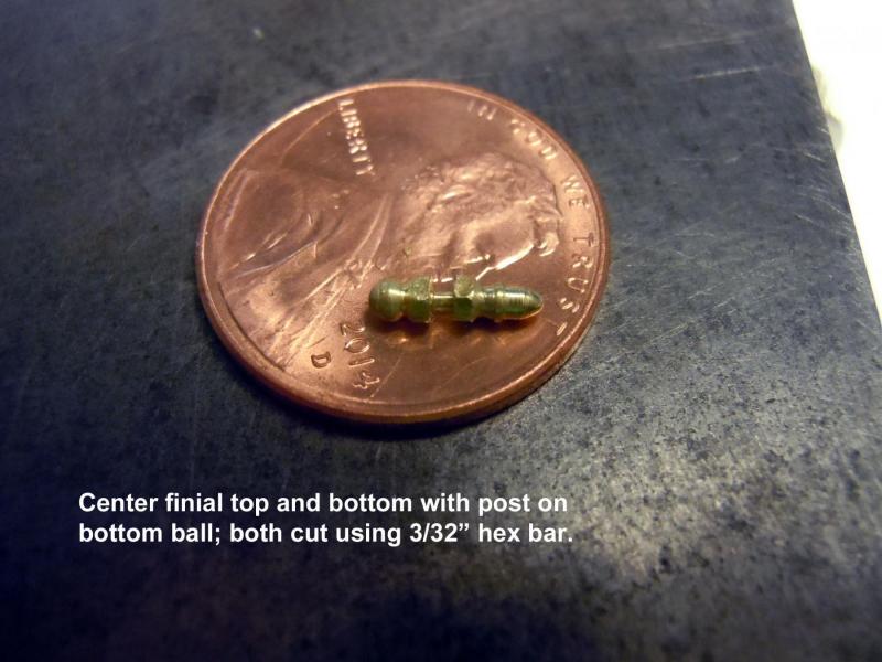
Thanks to Jon I had a better image of the center finial. I moved on and completed the first complete canopy. Following is a sequence of how I did them in detail for those who wish to try doing them. I could not find any other builds with details so hopefully not too much on these. These canopies are like the cherry on the top of a sundae and a critical element so I apologize if too images. Again thanks to Jon for his help with images! Also had a pleasant visit to our harbor to watch the San Salvador come in to Morro Bay for a 5 day visit. She was escorted by many of the local craft. Also the Chumash tribe sailed out to her in their authentic reed canoes in native dress. There was a heavy fog as you can see in the pictures. I will visit the ship to get more closeup details. If anyone needs a particular image please let me know.


-
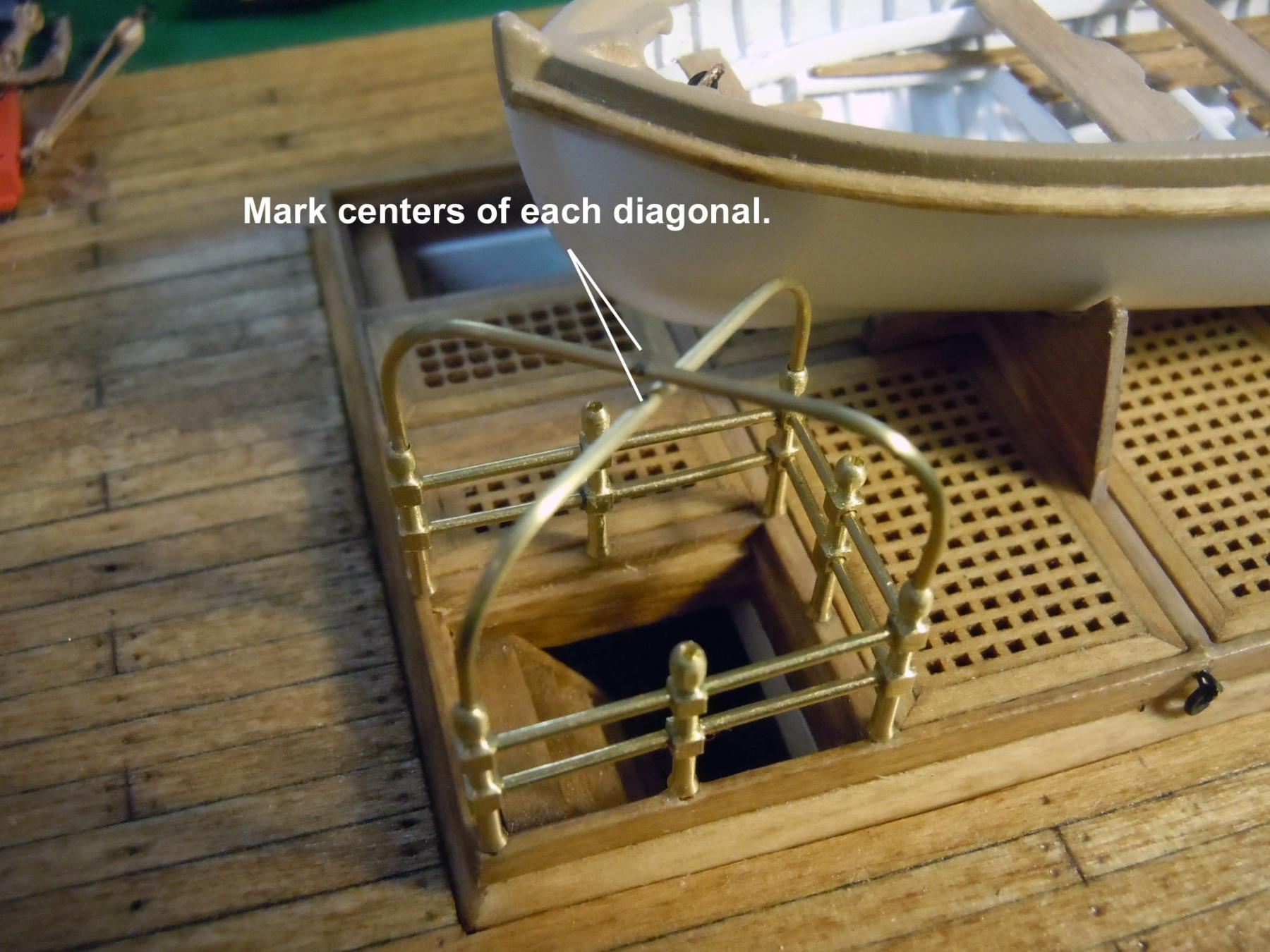
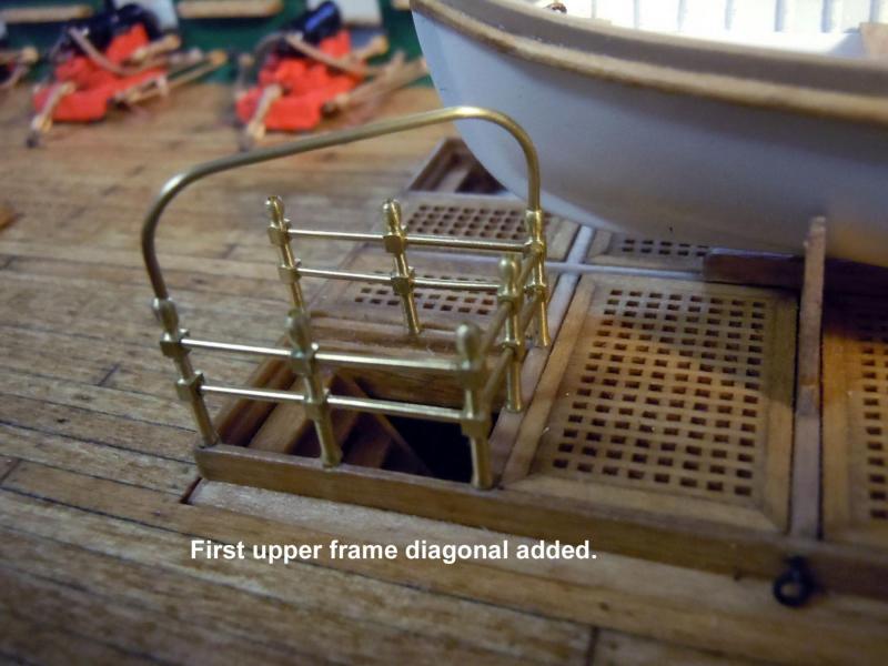
Jon, great picture! Again exactly what I needed to see for details. I just added the second frame diagonal so this is very timely. Thanks again! Ken
-
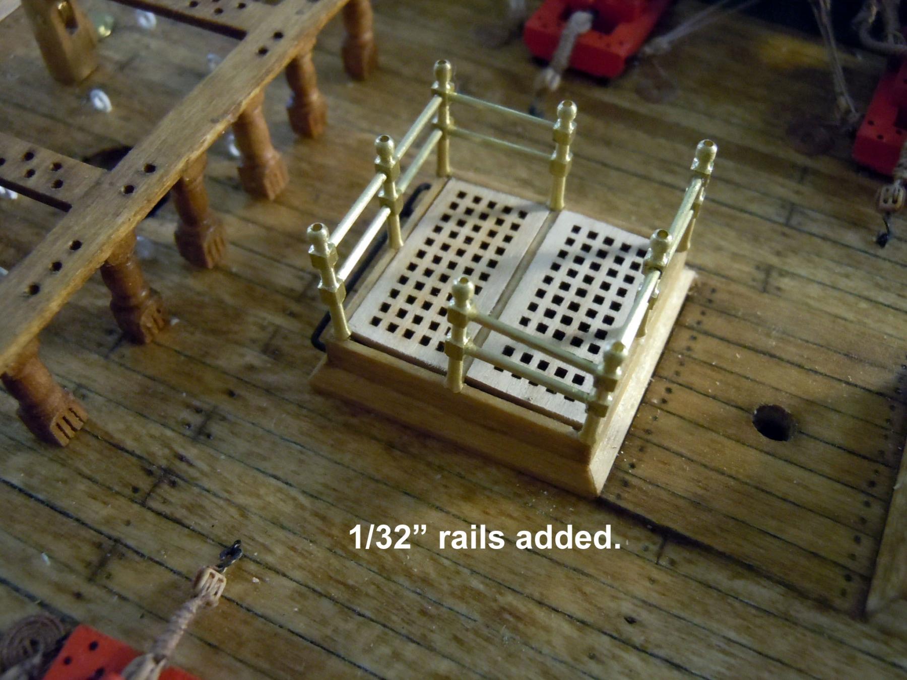
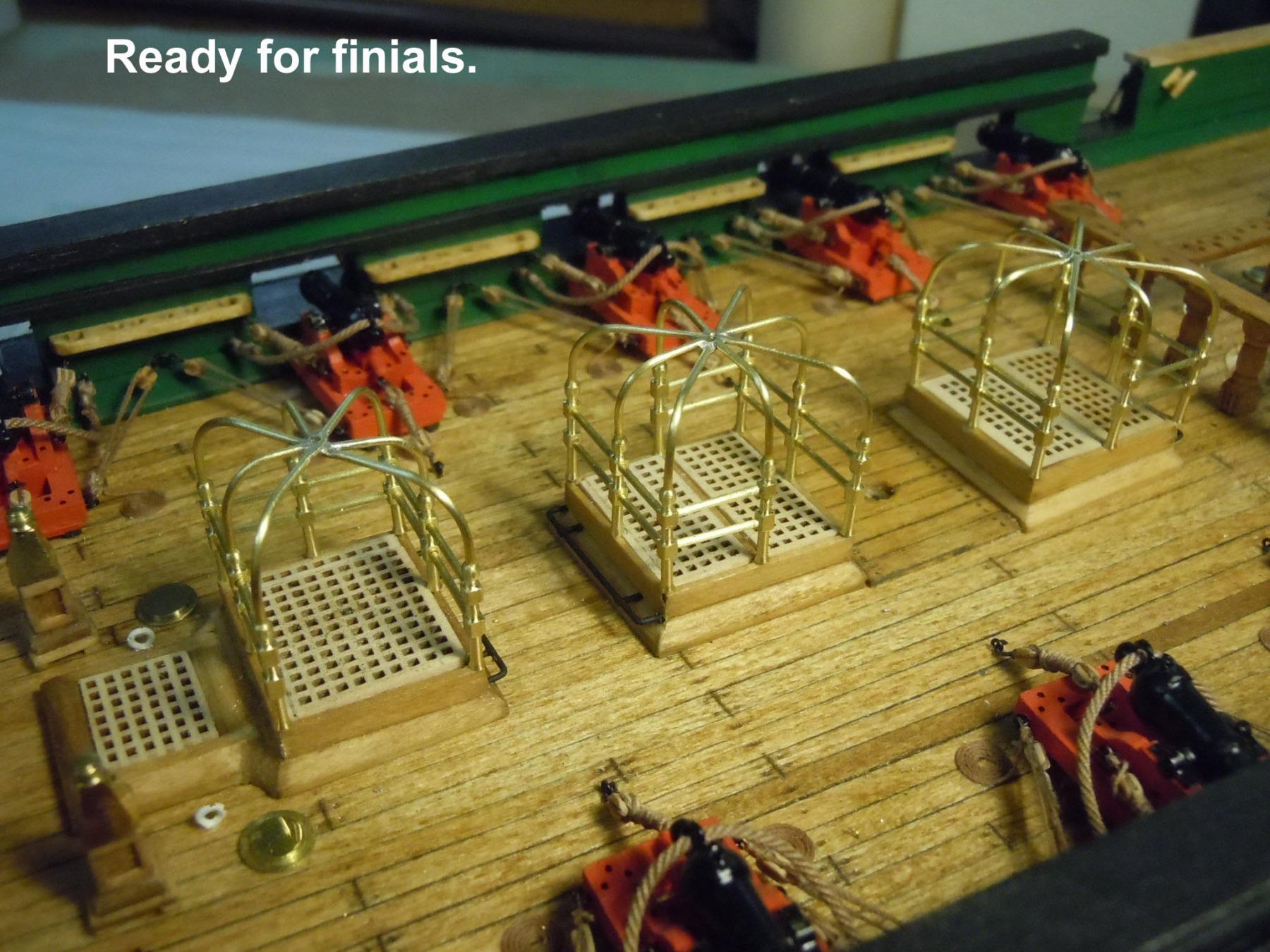
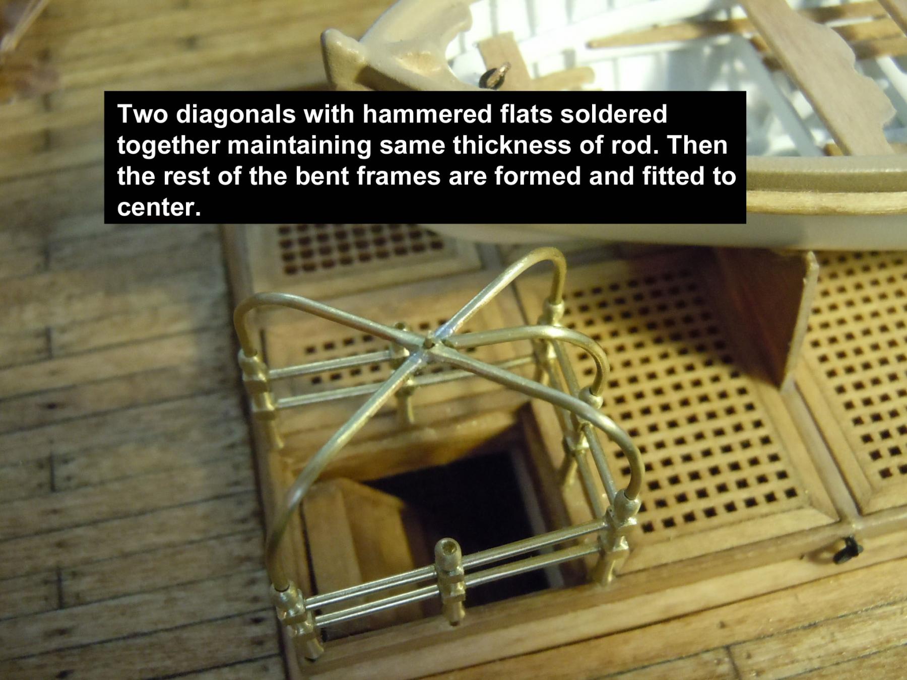
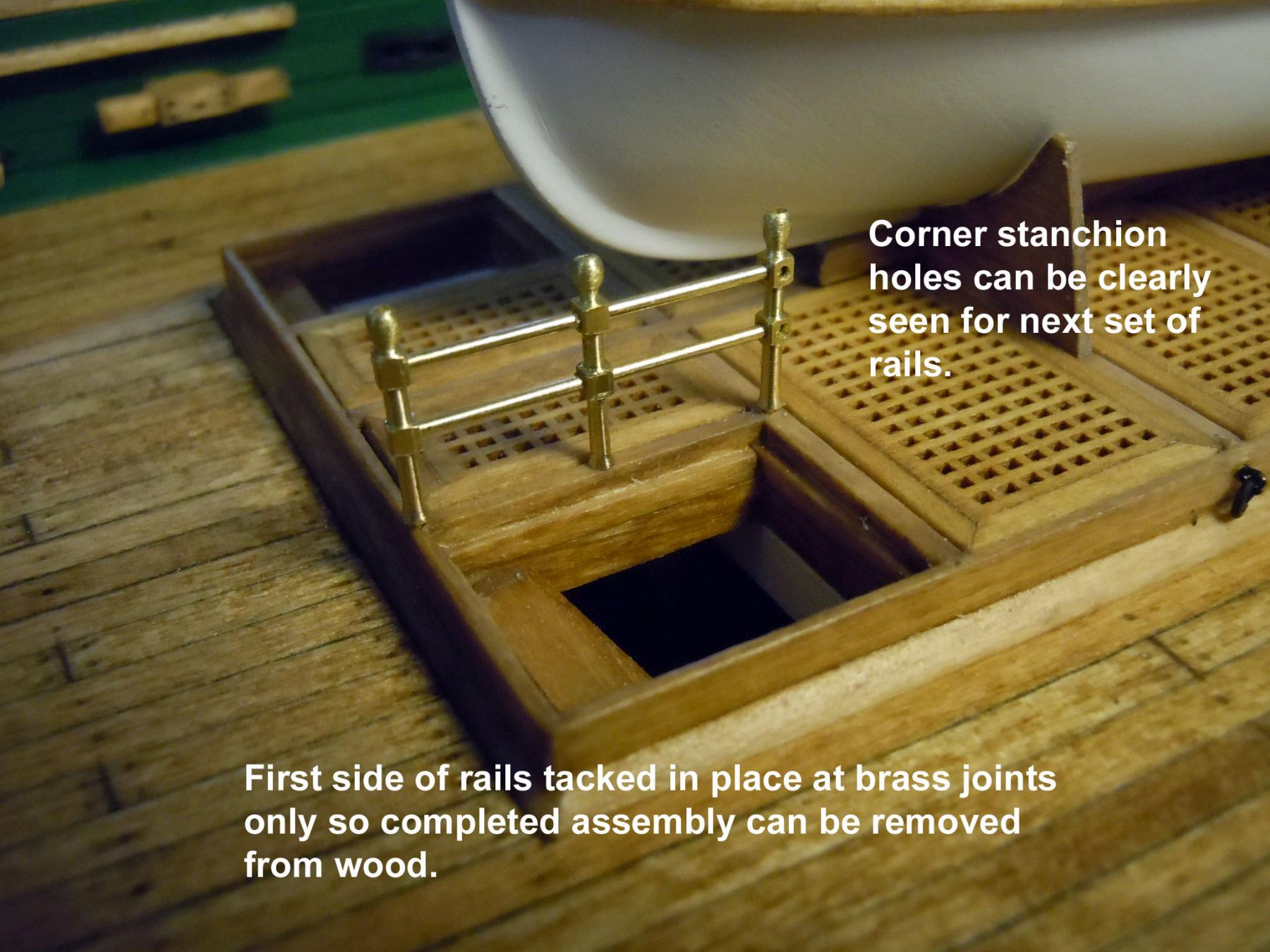
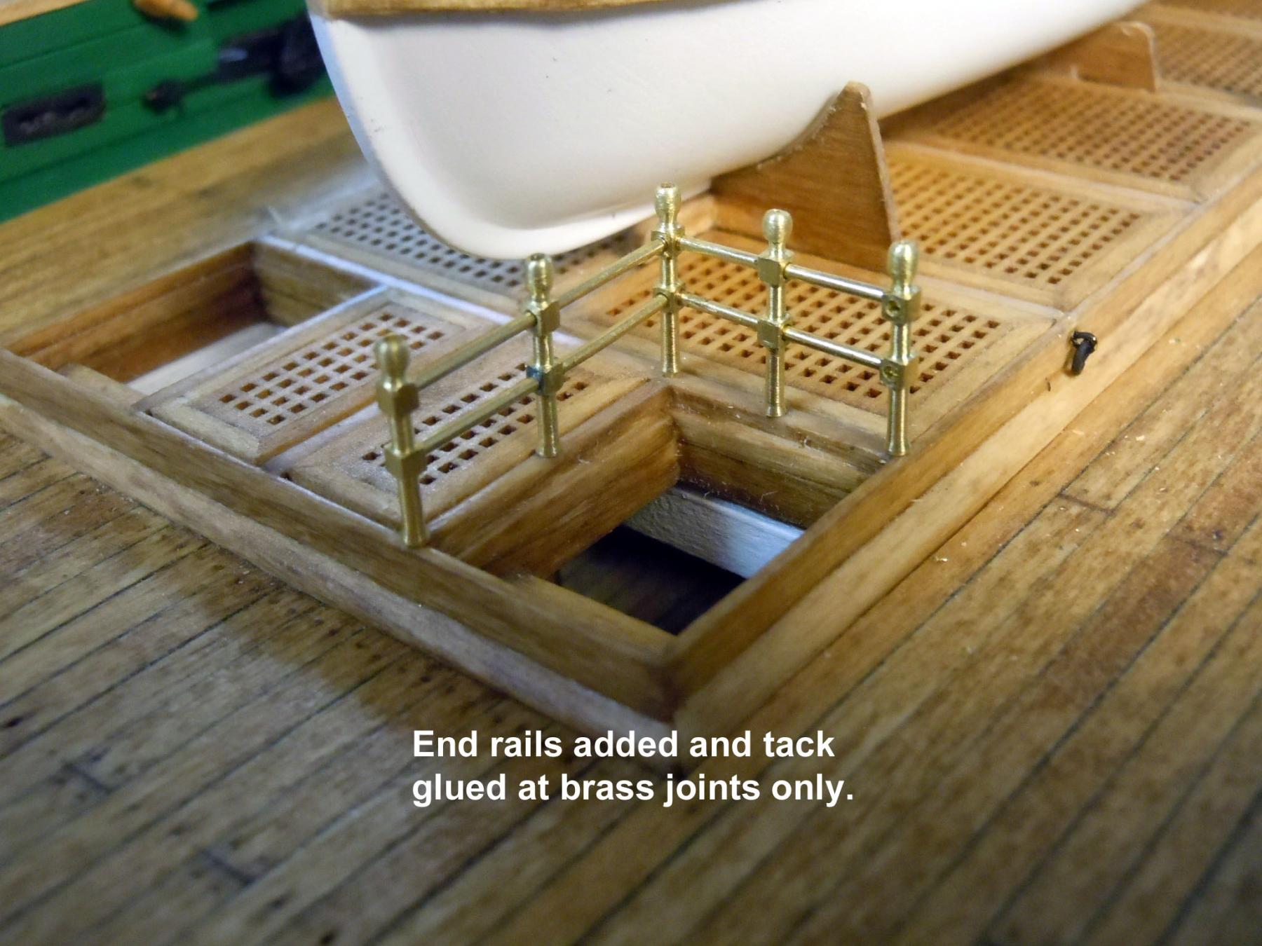
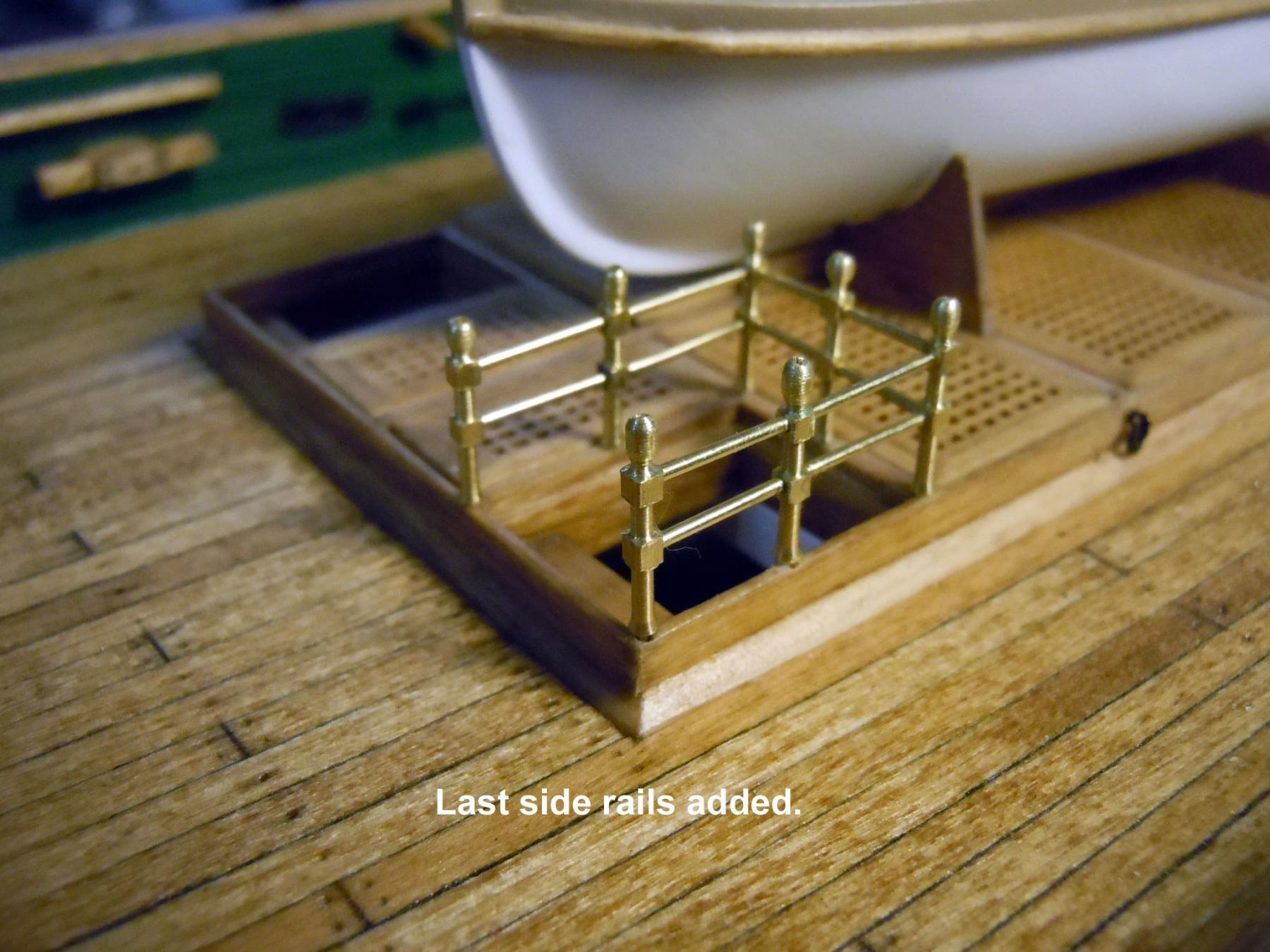
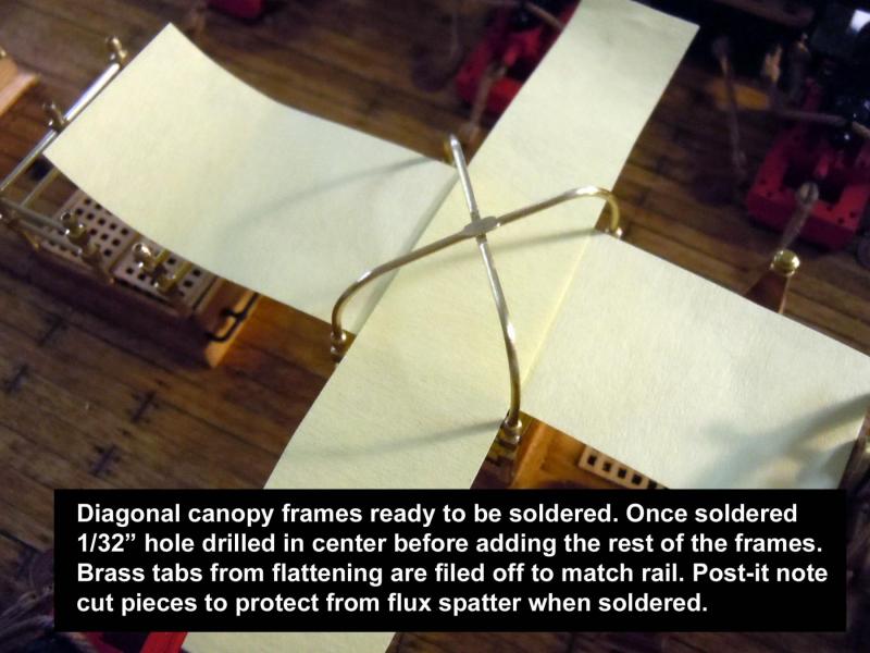
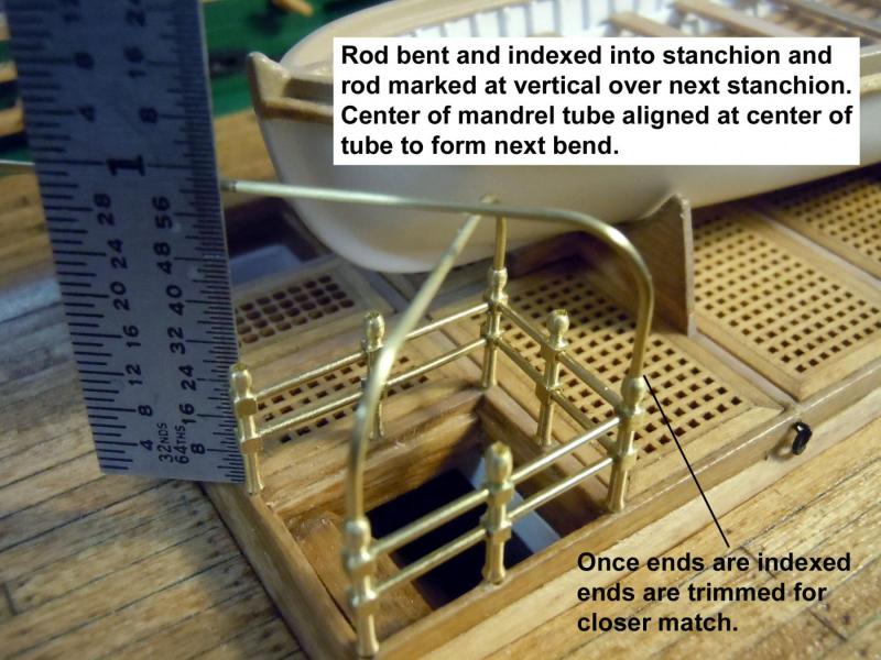
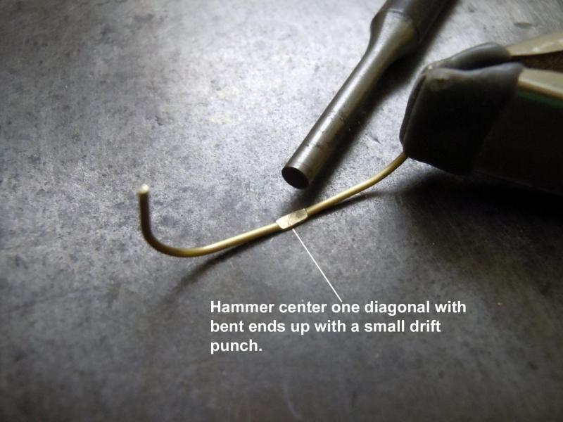
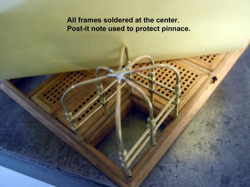
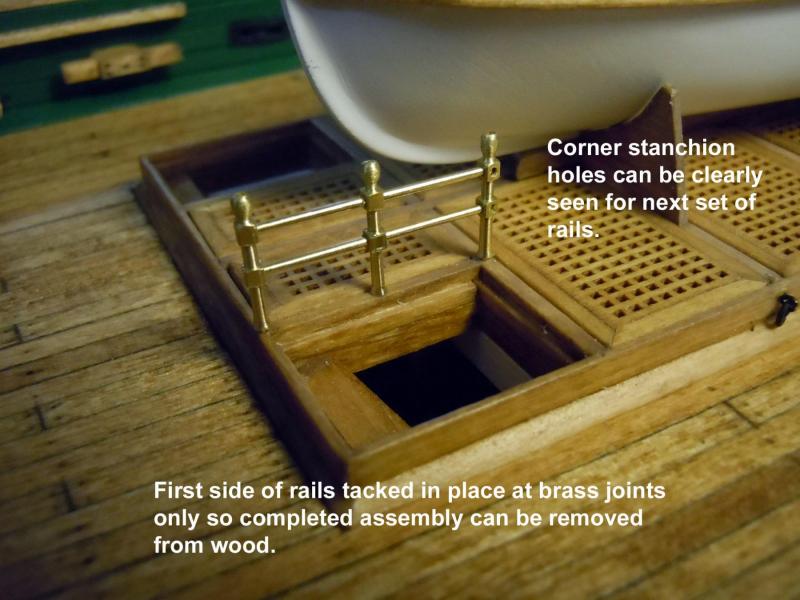
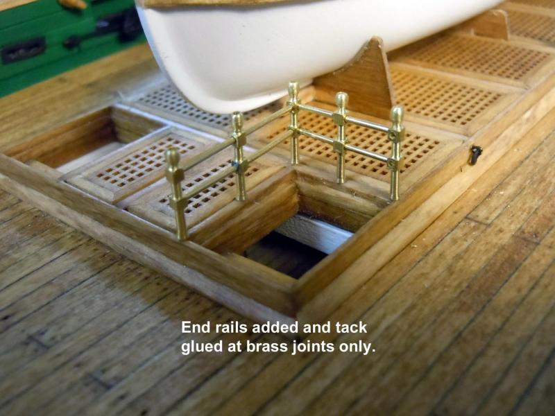
Jon, Scott, Joe thanks for your comments. Jon thanks for the link to the Pegasus his work his great and the design just different that that of the Constitution. The real challenge for this design is that the finish is brass rather than being painted. As turning away I thought that it might be wise to build one first before investing all the time in turning all the stanchions first. So I then drilled all the necessary parts for a complete unit. To borrow Scott's term I had a "Holy Crap" moment wondering if the bent upper frame would clear the bow of the pinnace and decided to do that canopy first. I first fitted the length of rails for the first side, positioned them in place first and tacked them with CA. I also once tacked laid the assembly on a steel block to assure flatness. Once the glue set I added the end set of rails and allowed the glue to set completely. Then the third side was added with careful filing of the end rails to get the correct fit before tack gluing. Next came the first diagonal frame and the moment of truth with the frame not coming near the bow of the pinnace. I bent the frame using a brass tube as a mandrel and matching the diagonal corners and inserting the ends into the 1/32" holes. I will turn little collar details later on for the ends that index into the holes. I chose the diagonal since it would provide the greatest strength for the free standing corner. I now feel comfortable that all parts will work so now back to turning while I think through the center upper frame finials. Also the unit is being built to be removable because soldering will be needed for the upper frame center joints.

-
Darrel, no lathe try a combination of materials of brass tubes and a wood top. Tubes can be cut for length of stack,slip ring from another tube, brass strips for connectors then shape a wood cap that could be painted and weathered with soot to blend. Just food for thought. Keep the great job you are doing.
- 648 replies
-
- 3
-

-
- niagara
- model shipways
- (and 1 more)
-
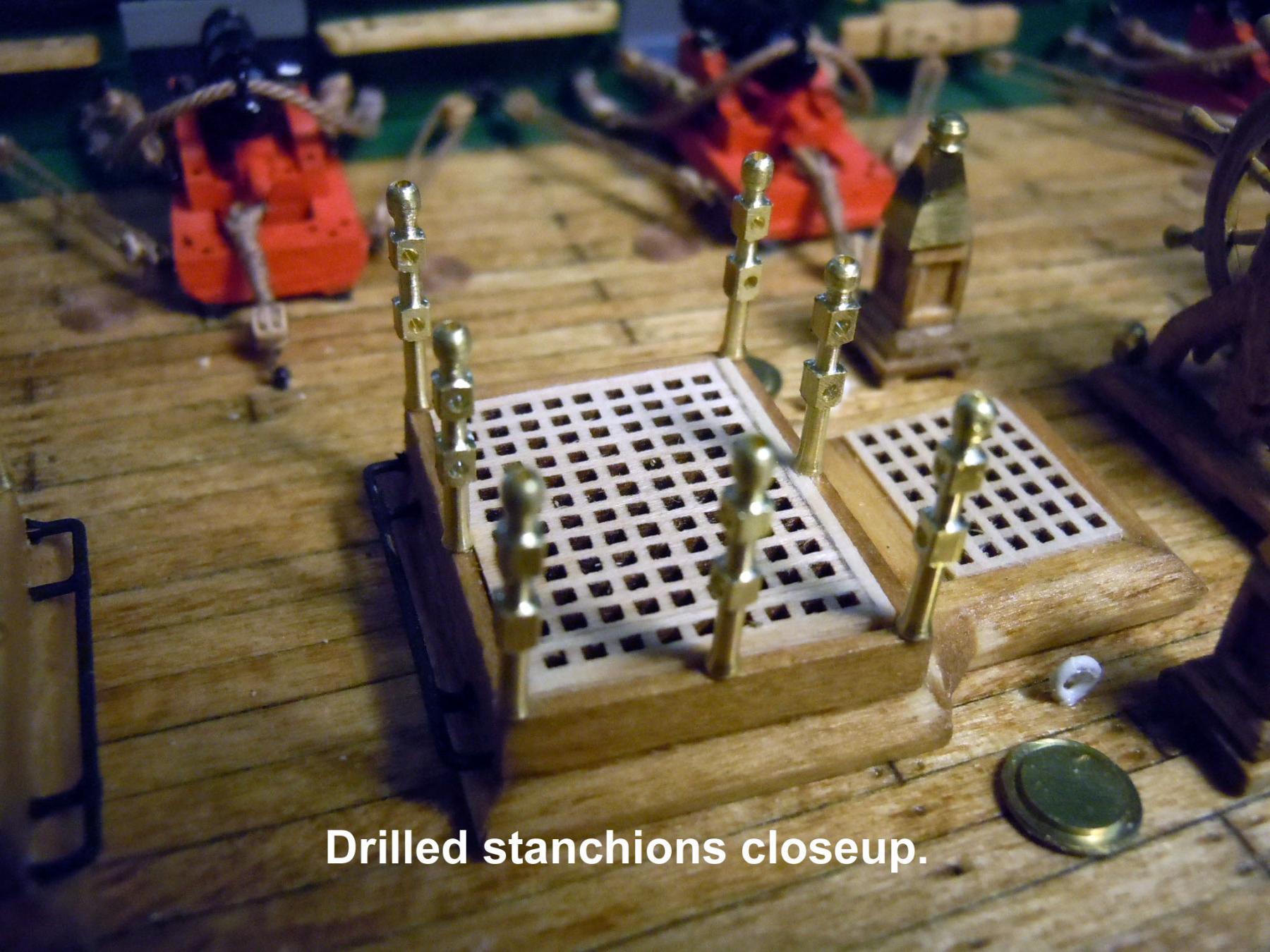
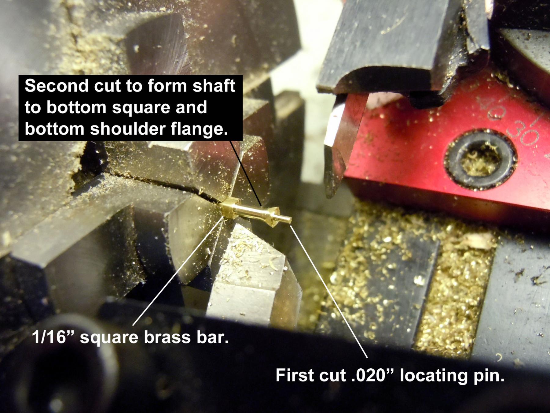
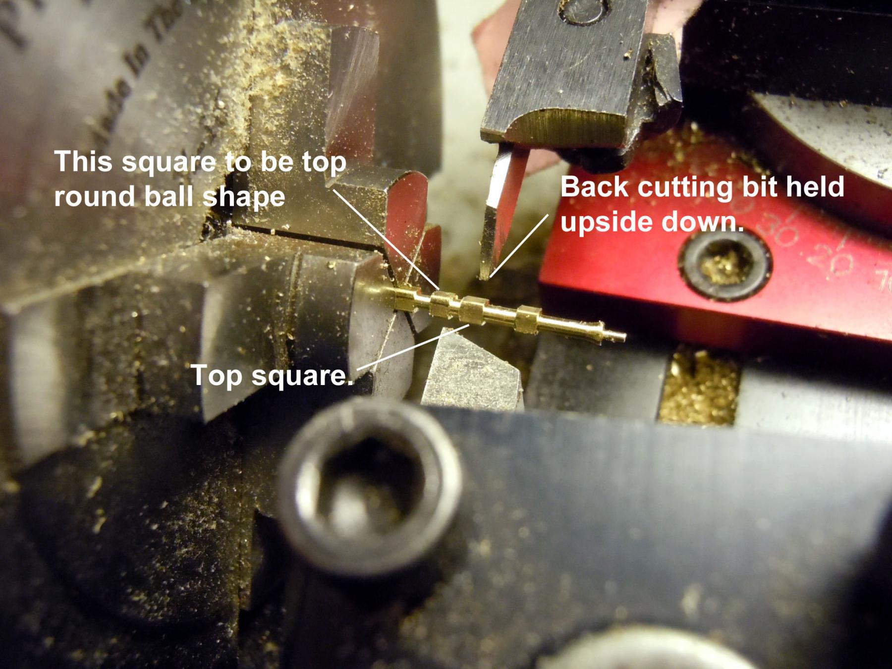
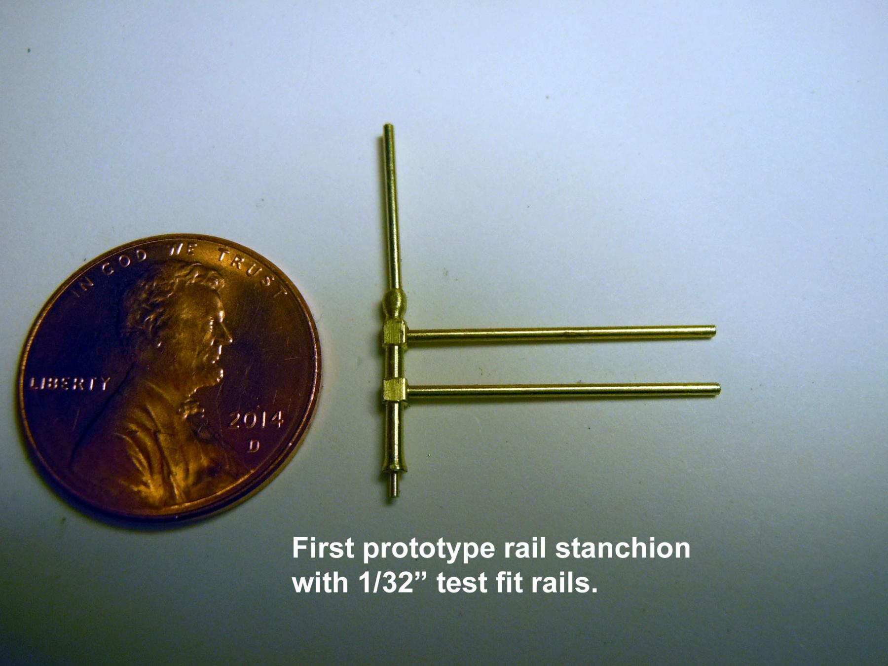
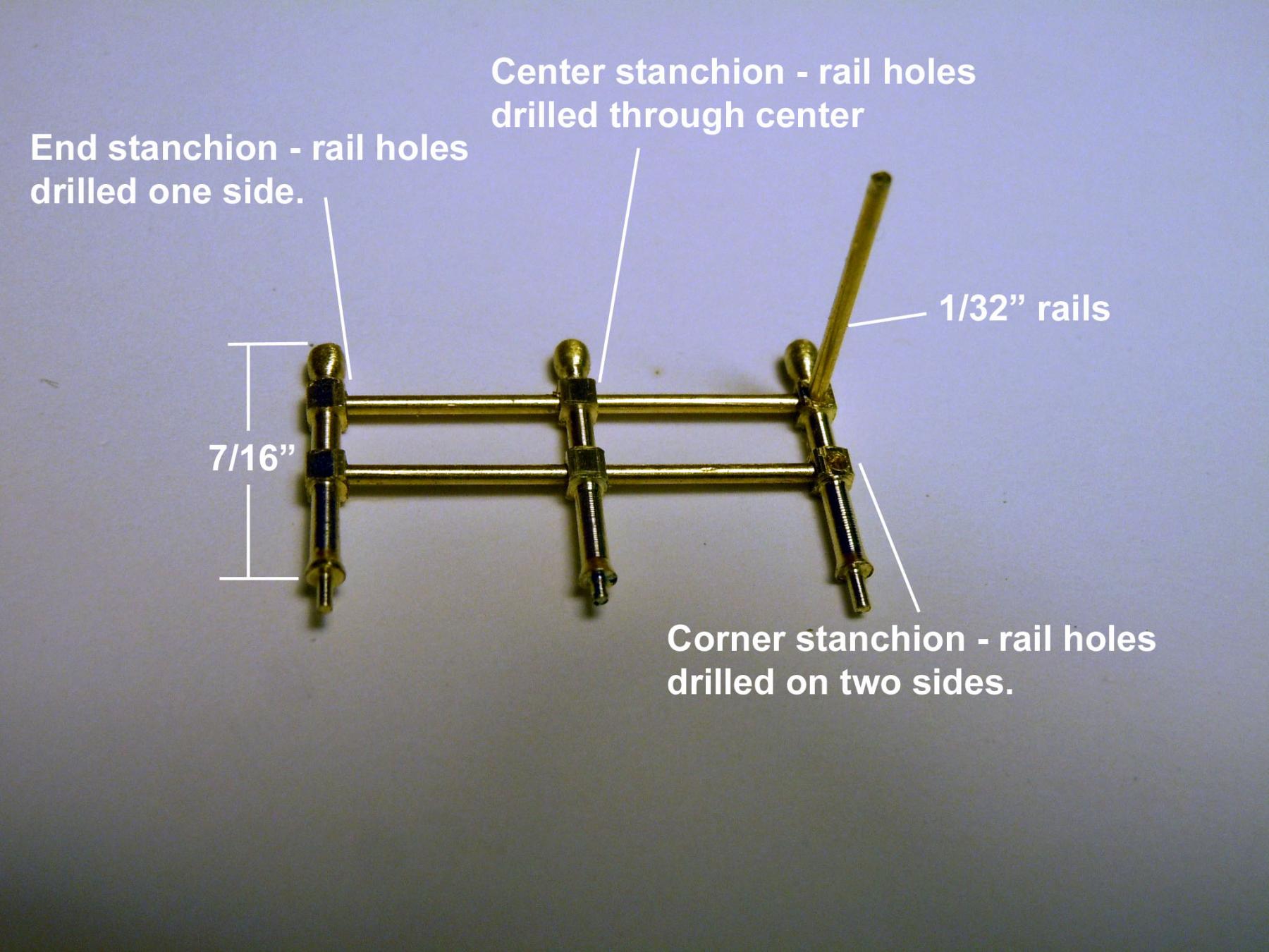
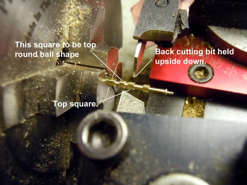
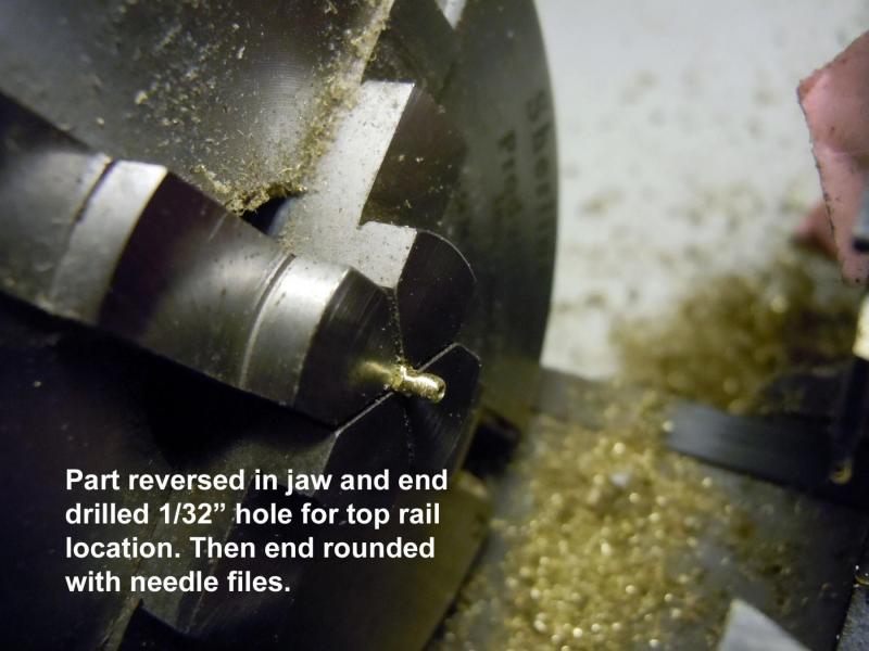
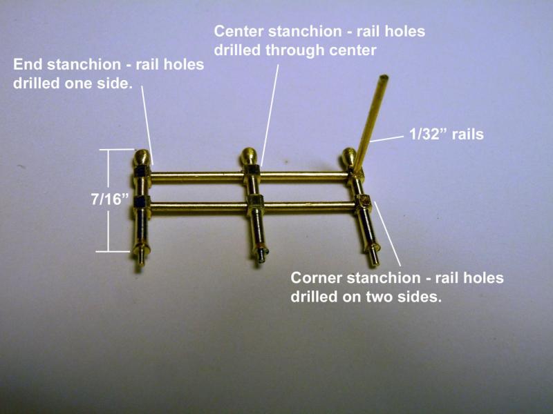
Captain Steve, thank you for your kind words! Well I pondered the best approach to fabricating the canopy frames for the hatchways and started first with what I considered the more challenging parts, the stanchions. I decided to turn them using 1/16" square brass bar on my Sherline lathe and use my combination slide to back cut with a second bit. This allowed one setup without having to change tool holders. I love this feature of the Sherline. I colored one side of the stock with a blue marker to mark the key locations from the locating pin shoulder up 7/16" to the top. First I cut the .020" locating pin then advanced the stock in the chuck. In turning small stock like this one must cut close as possible to the chuck and use cutting fluid. Next I cut the shank to the bottom of the first square down to the angled flange above the locating pin forming a shoulder. Next I used the back cutter to cut between the squares and also the top circular shape. The part was cut off and indexed back in the chuck to first drill the top with a 1/32" hole to receive the bent frames. Once the hole was drilled the rounded shape was formed carefully using a needle file. Once the first one was cut and drilled with the 1/32" location holes for the rails it was used as a "master" to mark the rest for cutting as close as possible of course using magnification to keep on track. I cut the first three and drilled for the three types that needed to be drilled differently. The end requires 10 parts drilled one side, the center requires 15 parts drilled completely through for the rail, the corners require 12 parts drilled two adjacent sides to receive the rails. Here are a sequence of pictures that show where I am so far. Here are the results of the back cutting tool. Now that I have a system down back to cutting and drilling the 34 more to turn. This may take awhile and I will think of other things to do when my eyes need a break form cutting this small.


-
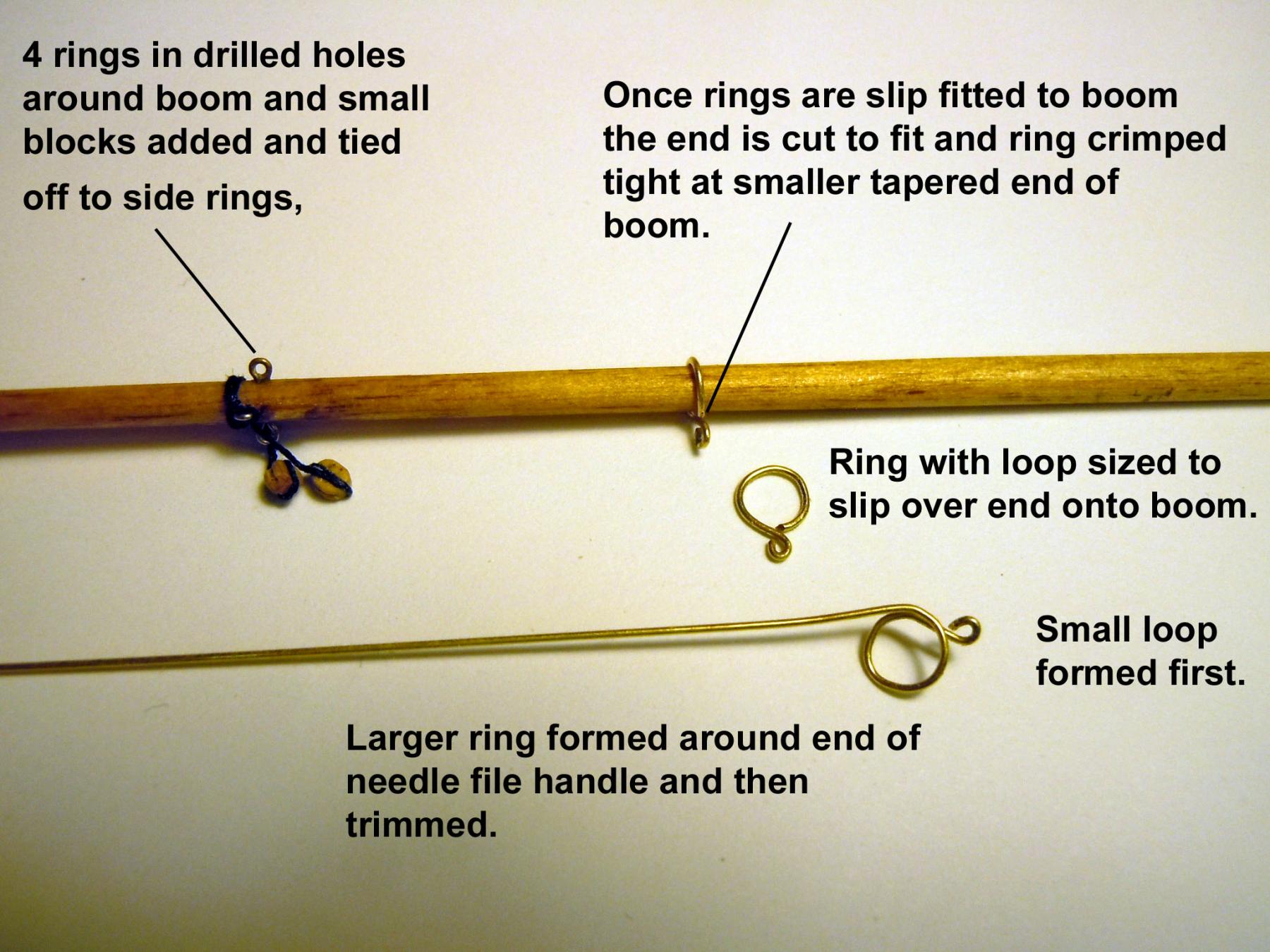
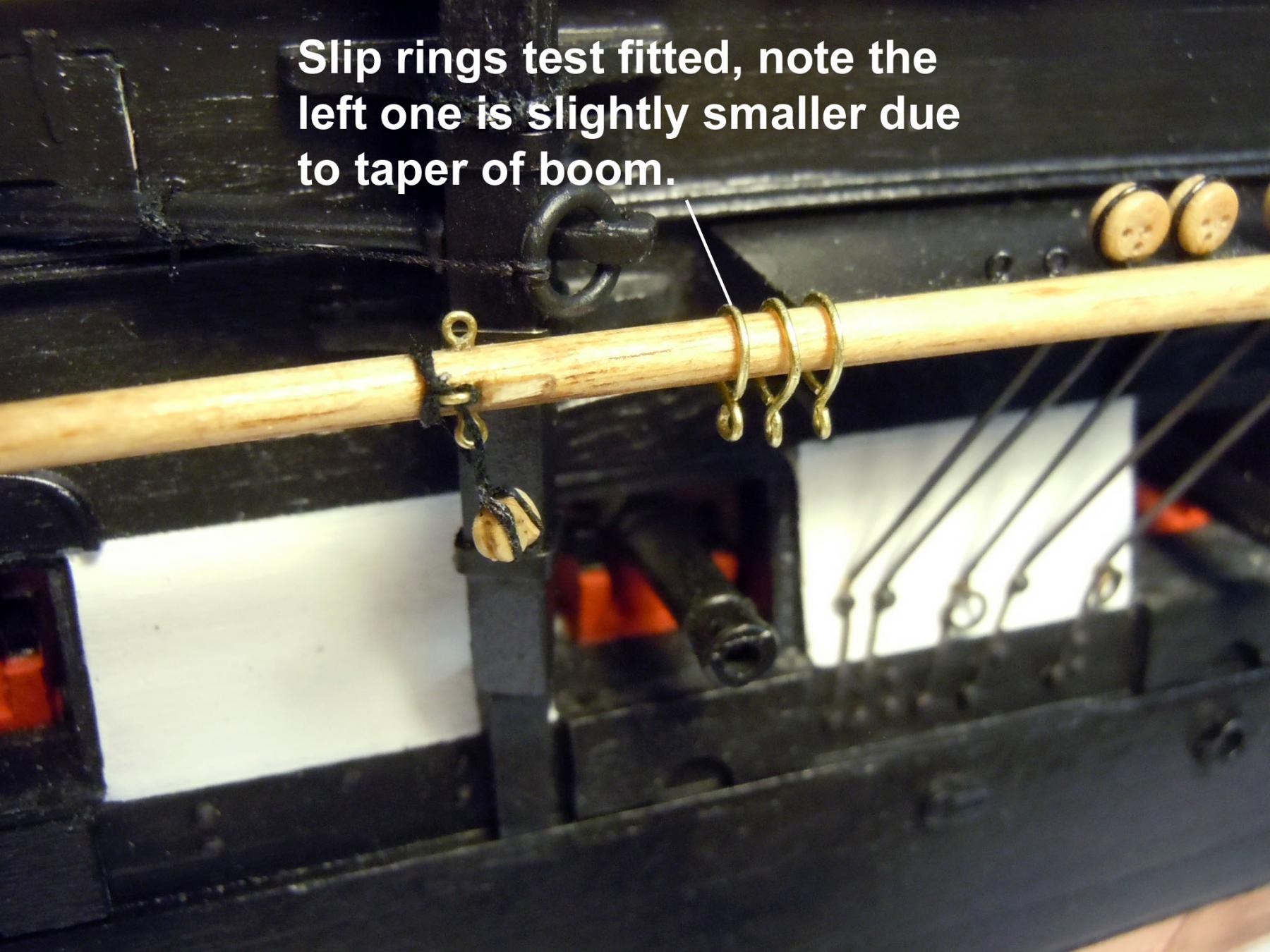
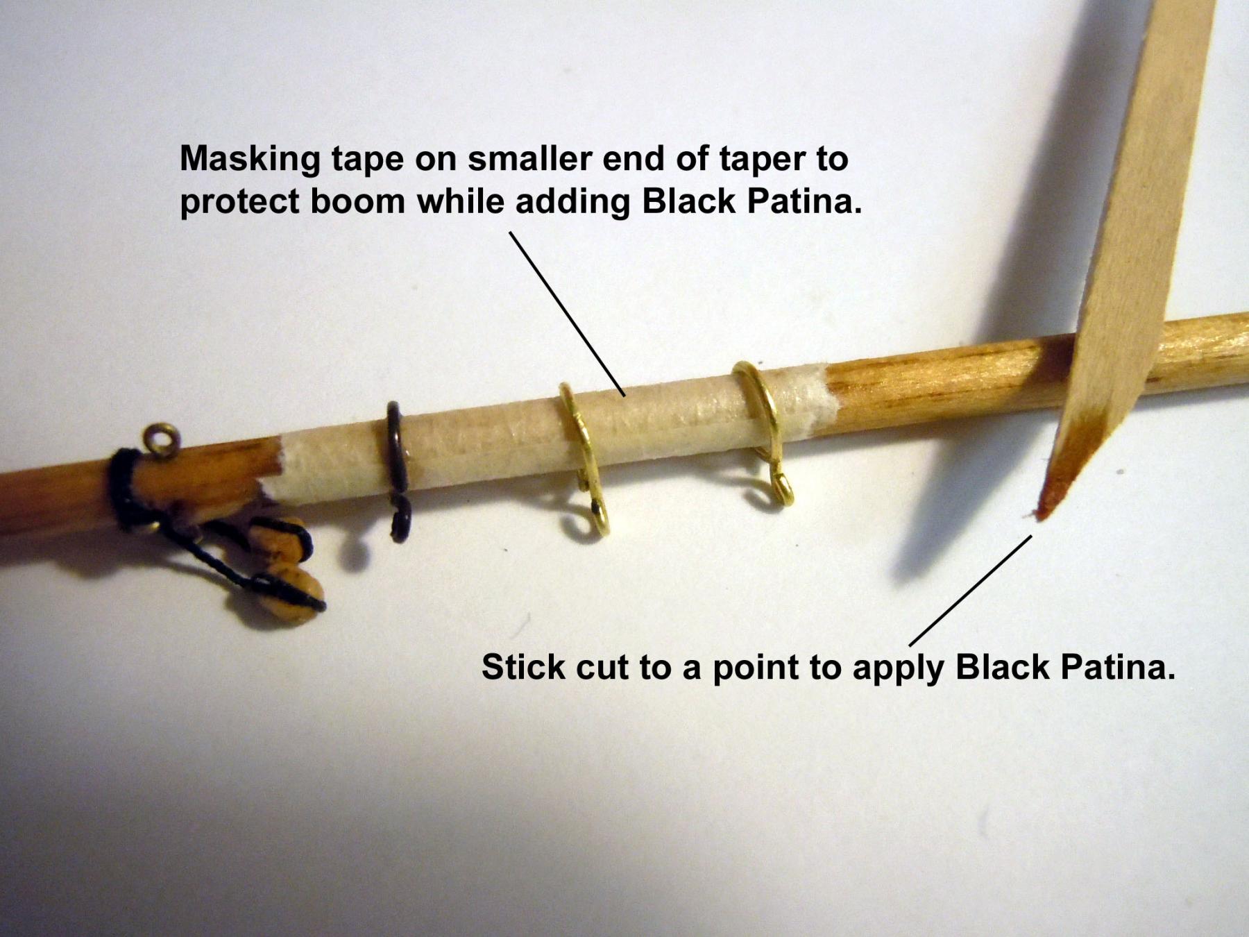
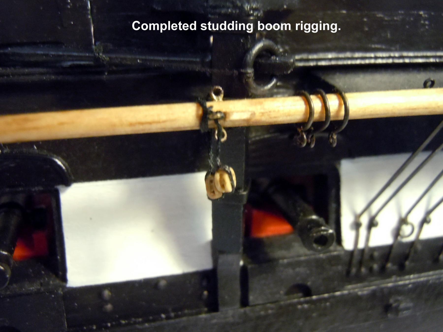
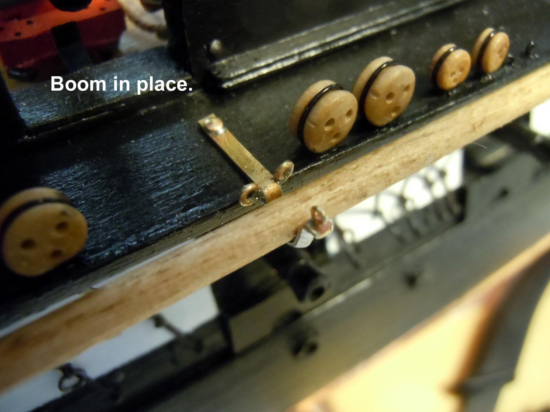
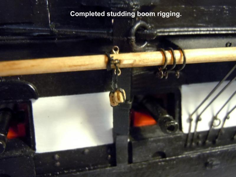
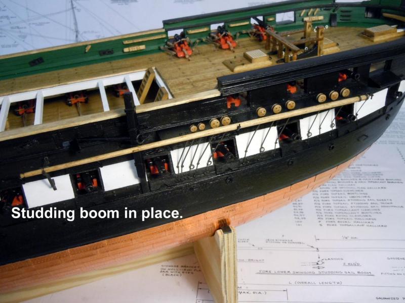
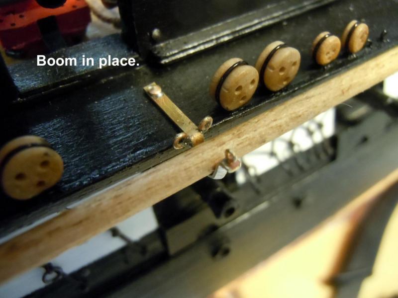
Jon thanks again for help with reference photos, I continue to be impressed with the plans lack of final details on certain elements that would have been so easy to add. Here is a sequence of details based upon your photos and I can only guess that the slip rings are for the sail. One other question you may be able to answer, I have seen in some images a second studding boom rigged to the main mast. Do you have any info on it? After formed, the rings were final fitted on the boom with end being trimmed as needed and tightened on the boom for a slip fit. I darkened the rings once final fitted due the scratch that would have happened with tool marks. Here is an overview of the boom lashed in place. Now to fiquire out my next move which may be the brass stanchions for the hatch covers.


-
Jon, thanks exactly what I needed! I suspected a couple of blocks but the ring is a nice detail. Thanks again!
-
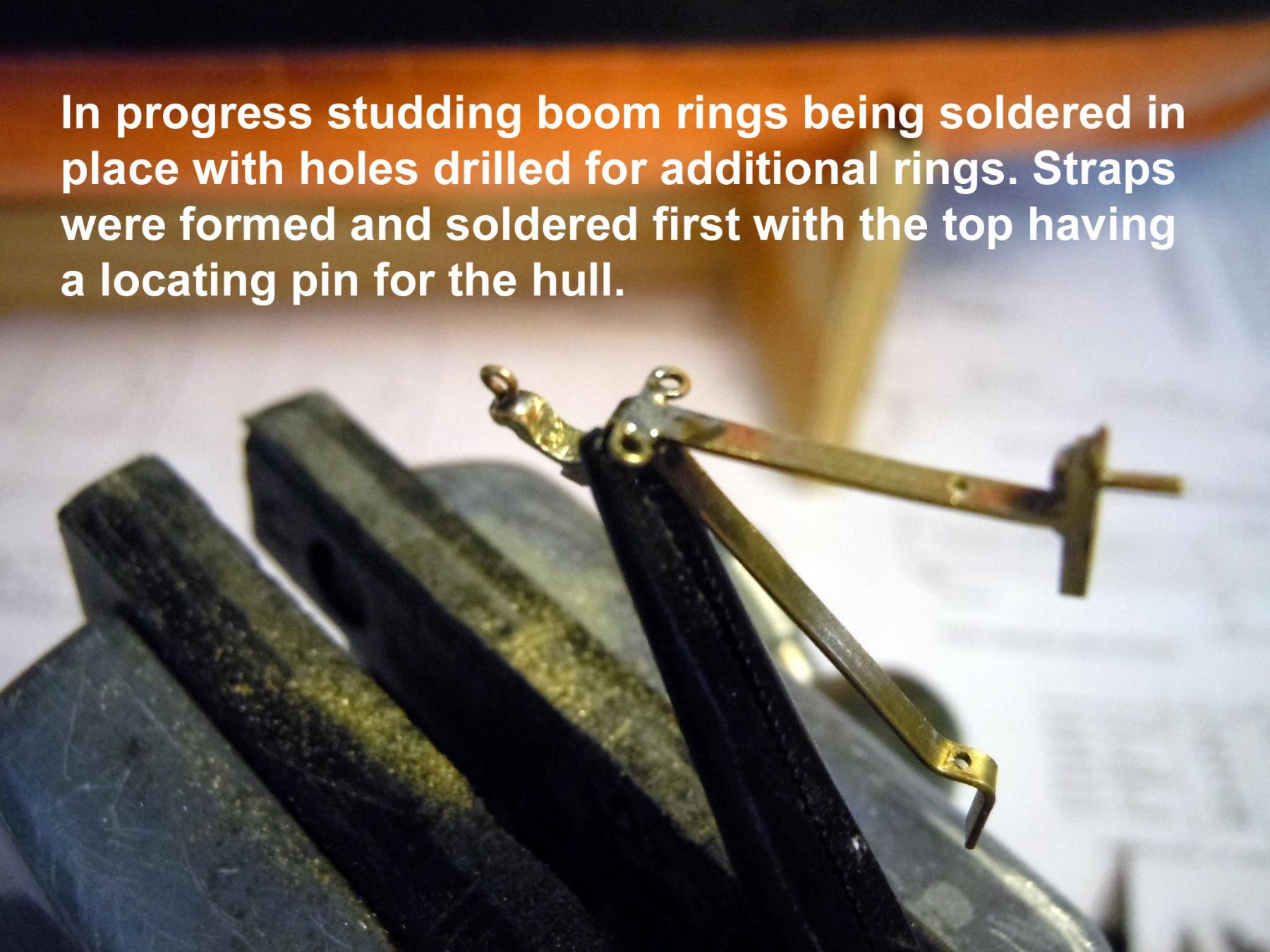
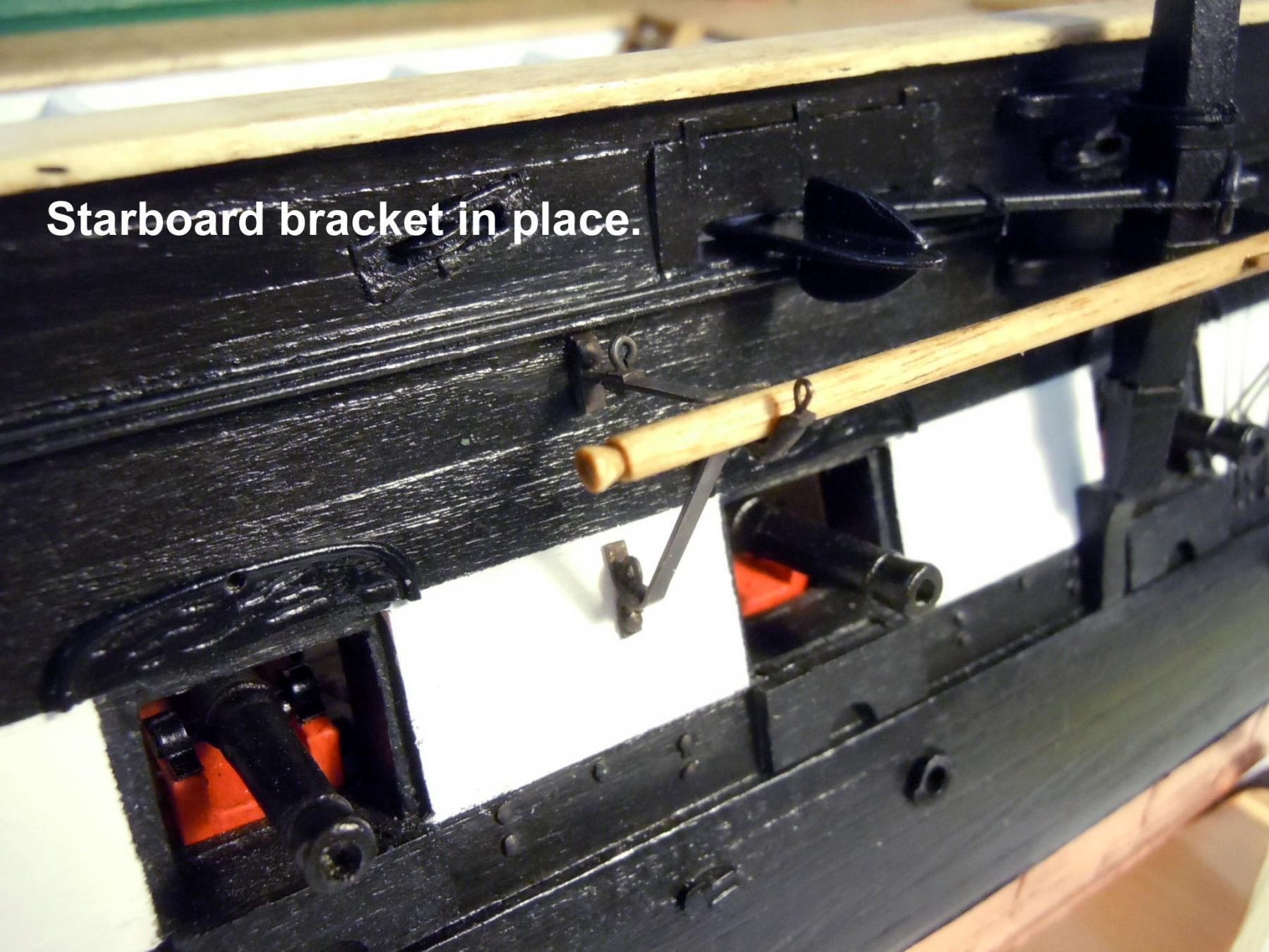
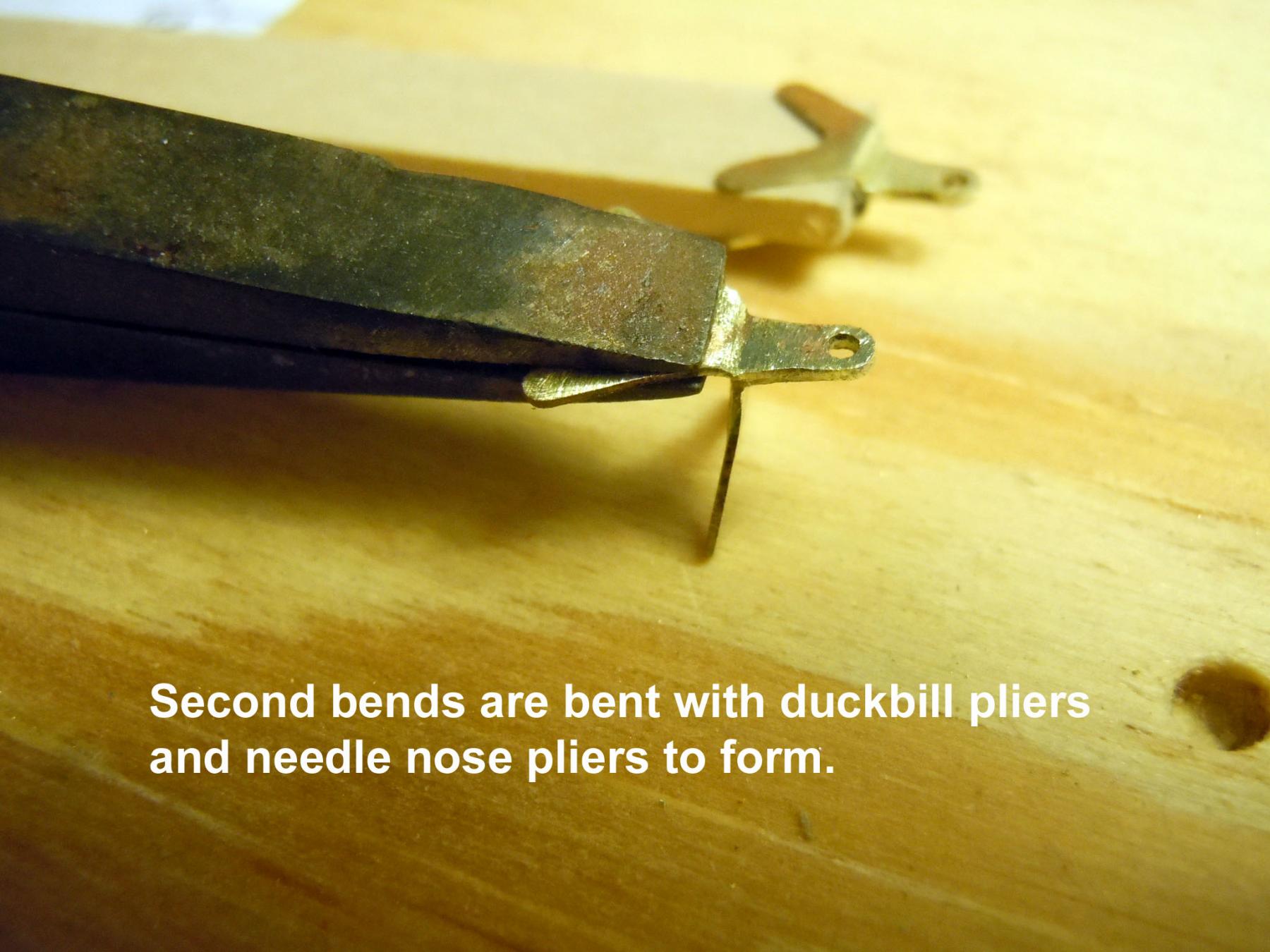
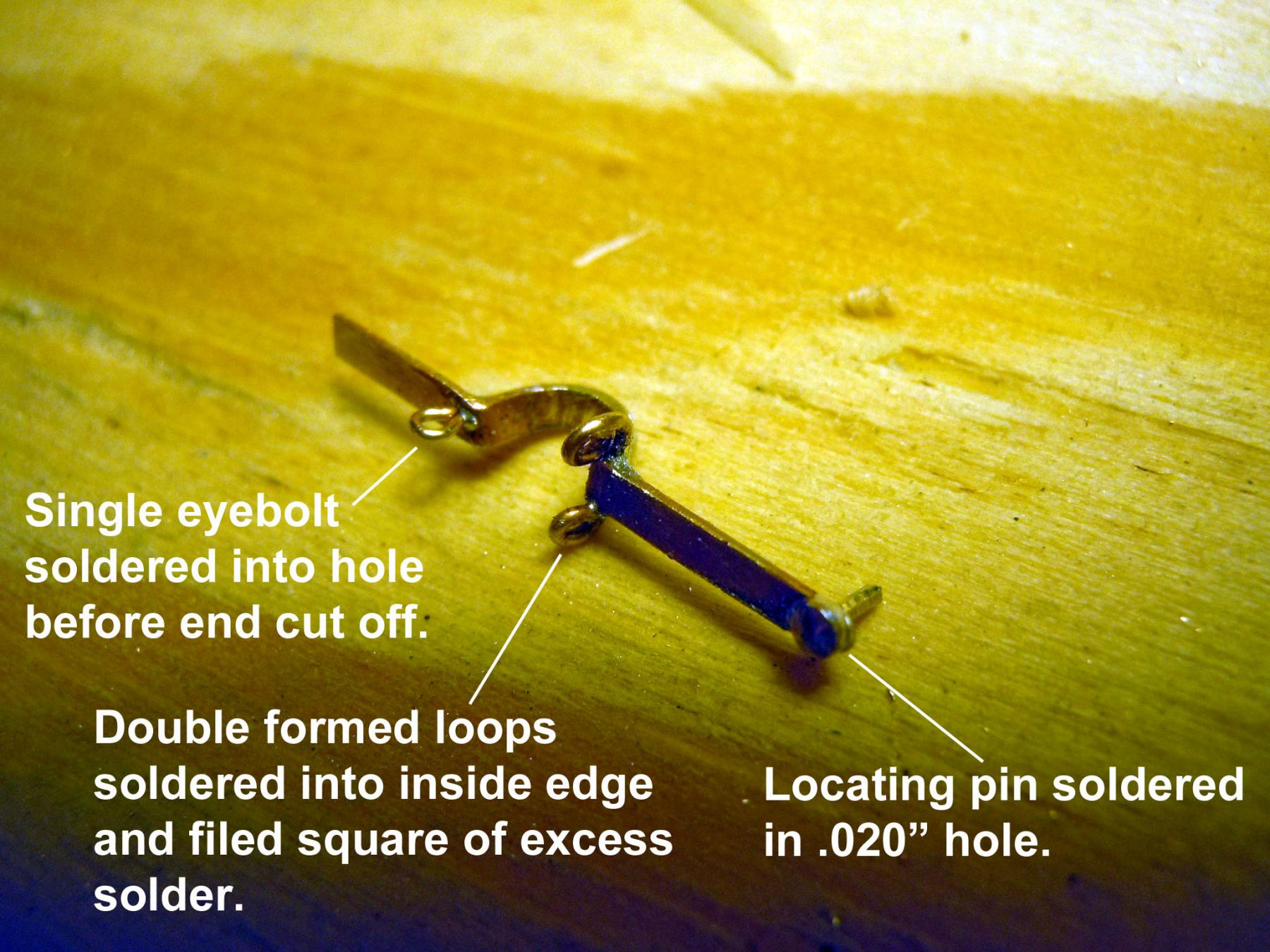
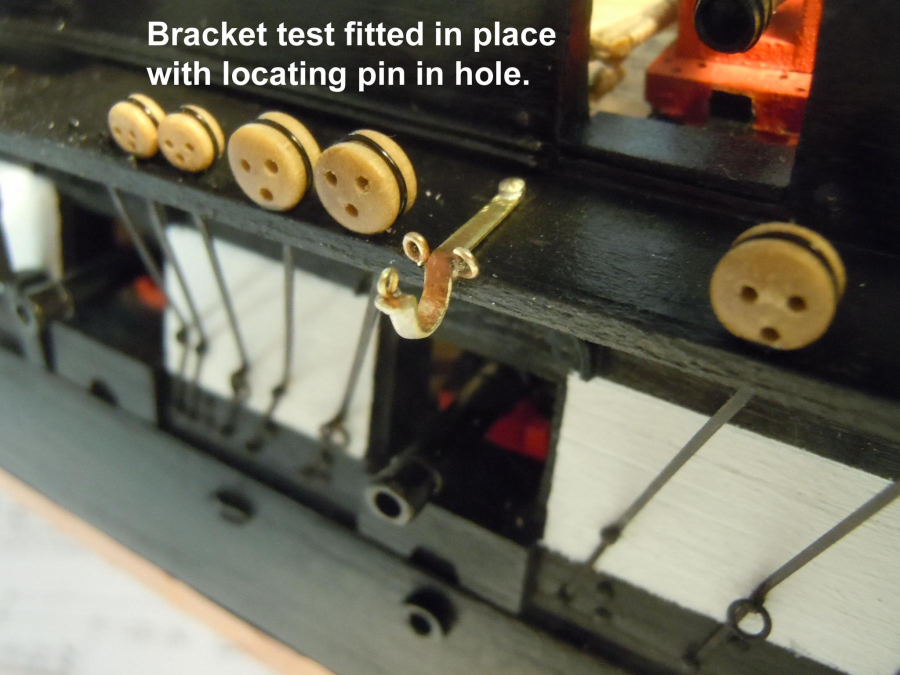
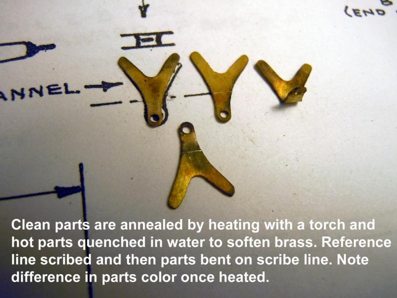
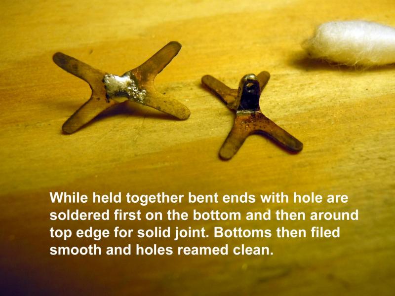
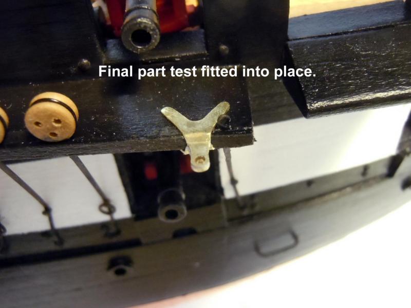
Thanks to Jon's great picture I was able to fabricate these two rear brackets for the studding boom. here is an in progress picture showing the main straps that were bent and soldered together and then drilled for rings and this picture shows the double ring being soldered in place. Once soldered together they were adjusted to mate to the hull, blackened and then glued in place. This shows the rear bracket. Here are a couple of overviews. Now to add the tackle blocks to the cleat area and ends of the booms themselves before lashing them to the brackets. If anyone has any info or details of these blocks it would be appreciated.


-
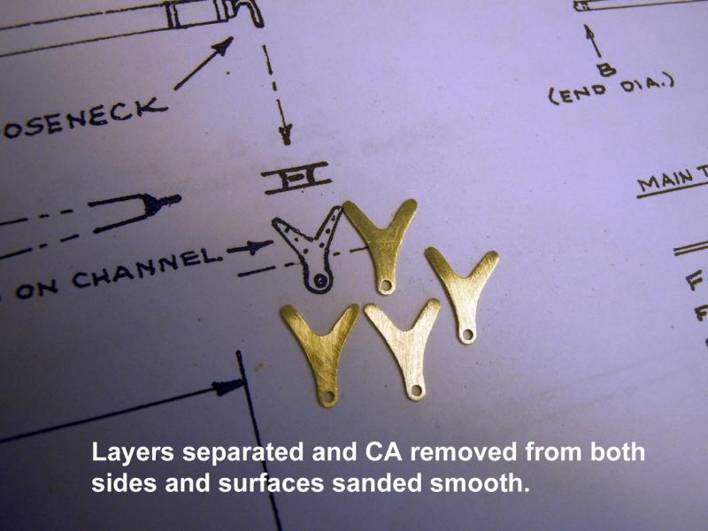
Jon, I am working on that bracket right now, great picture and these loops will be like the picture. I do not have a clear picture of the center bracket, but could see that the outside loop was vertical so I made the inne r ones the same. Do you have a picture of that center bracket? The parts pop apart by putting a blade on an edge to separate and then just scrape off the CA with the back edge of blade and sand. If not in a hurry you could soak them in acetone.
-
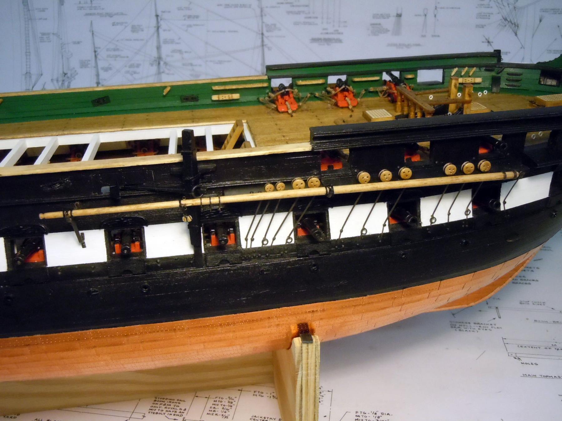
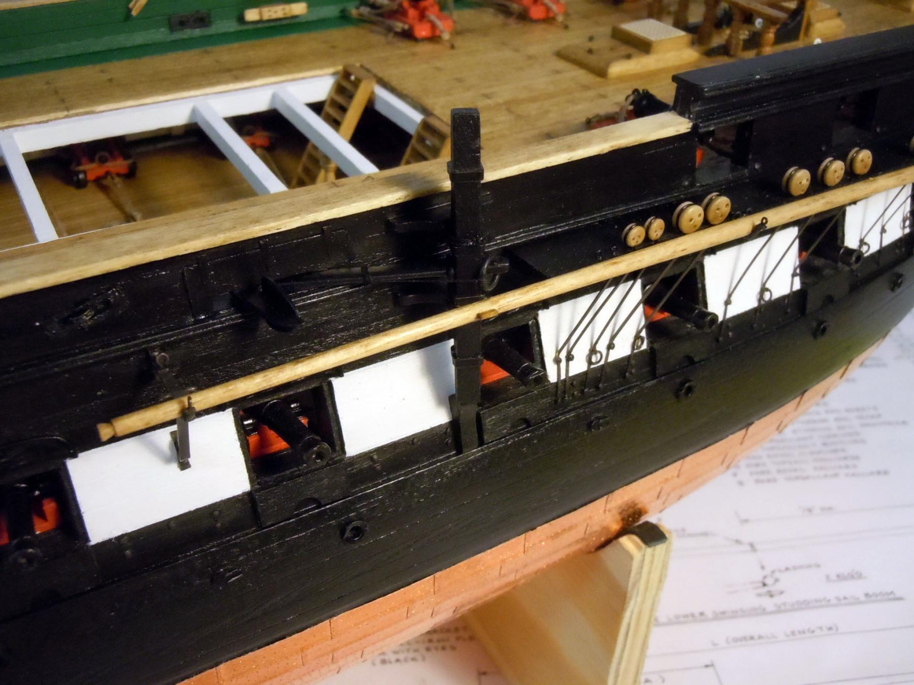
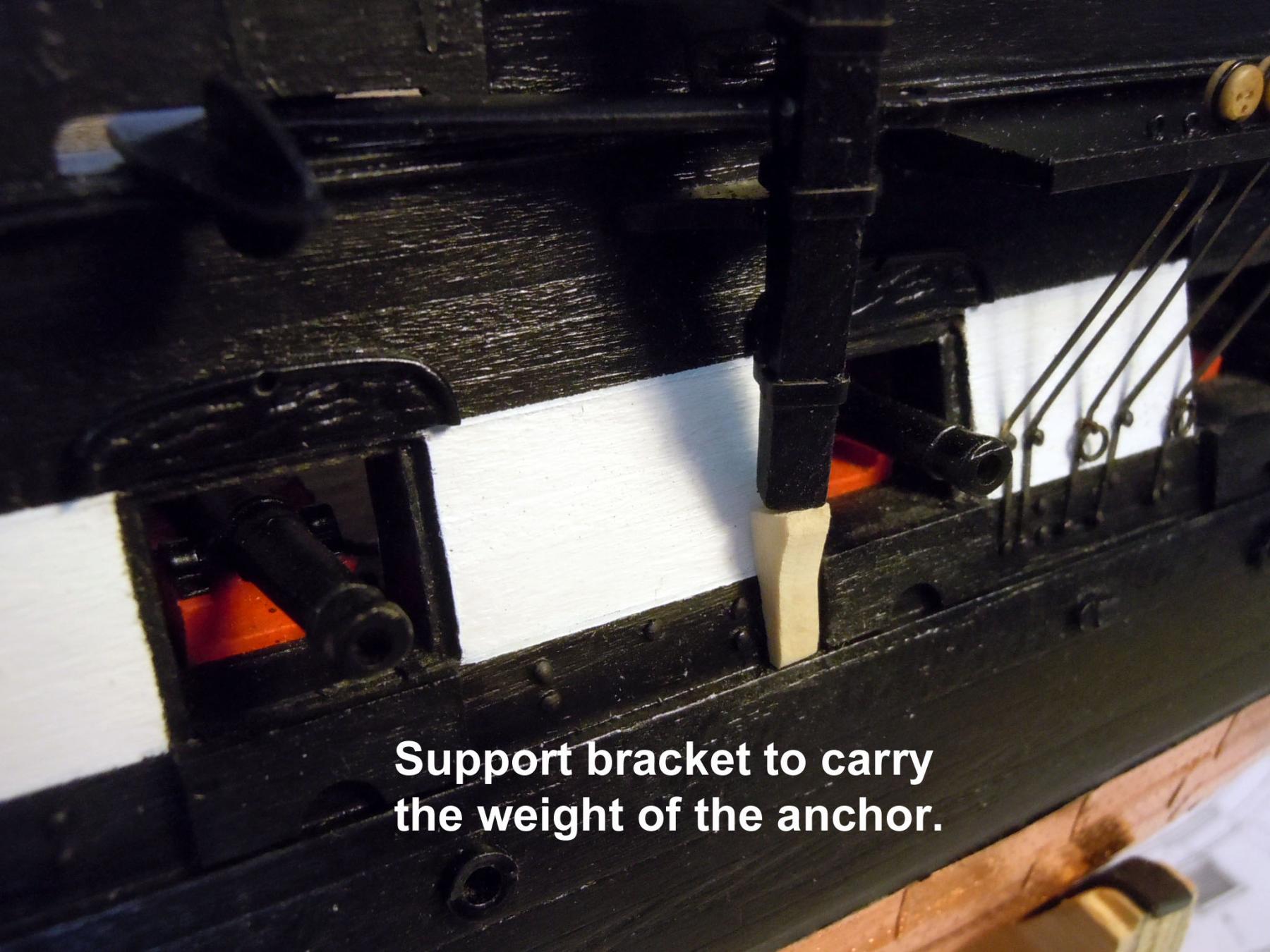
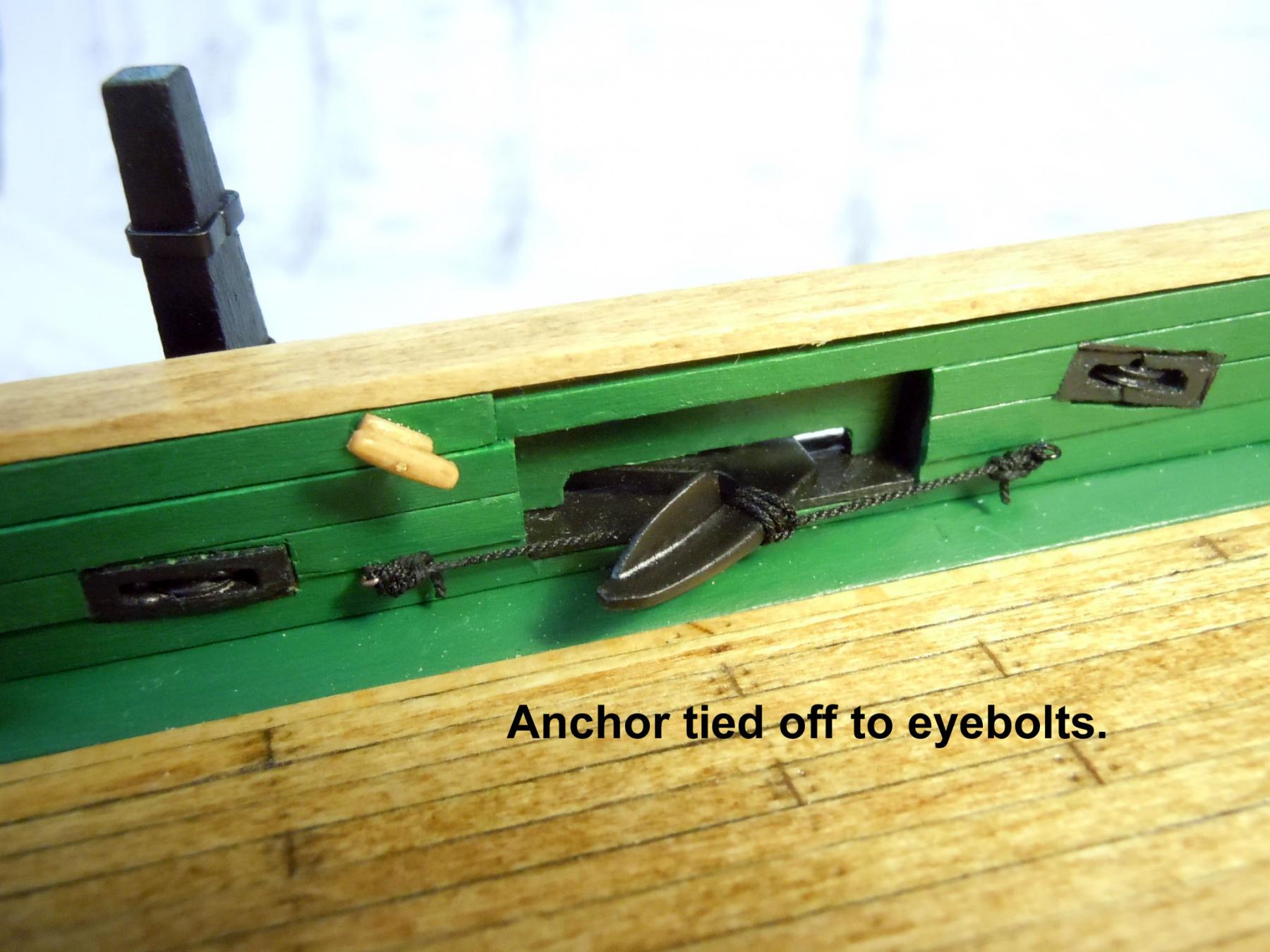
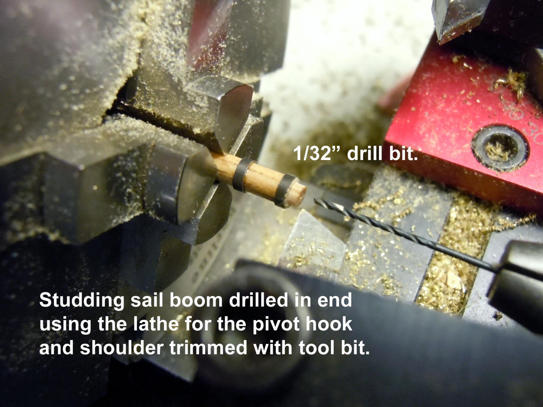
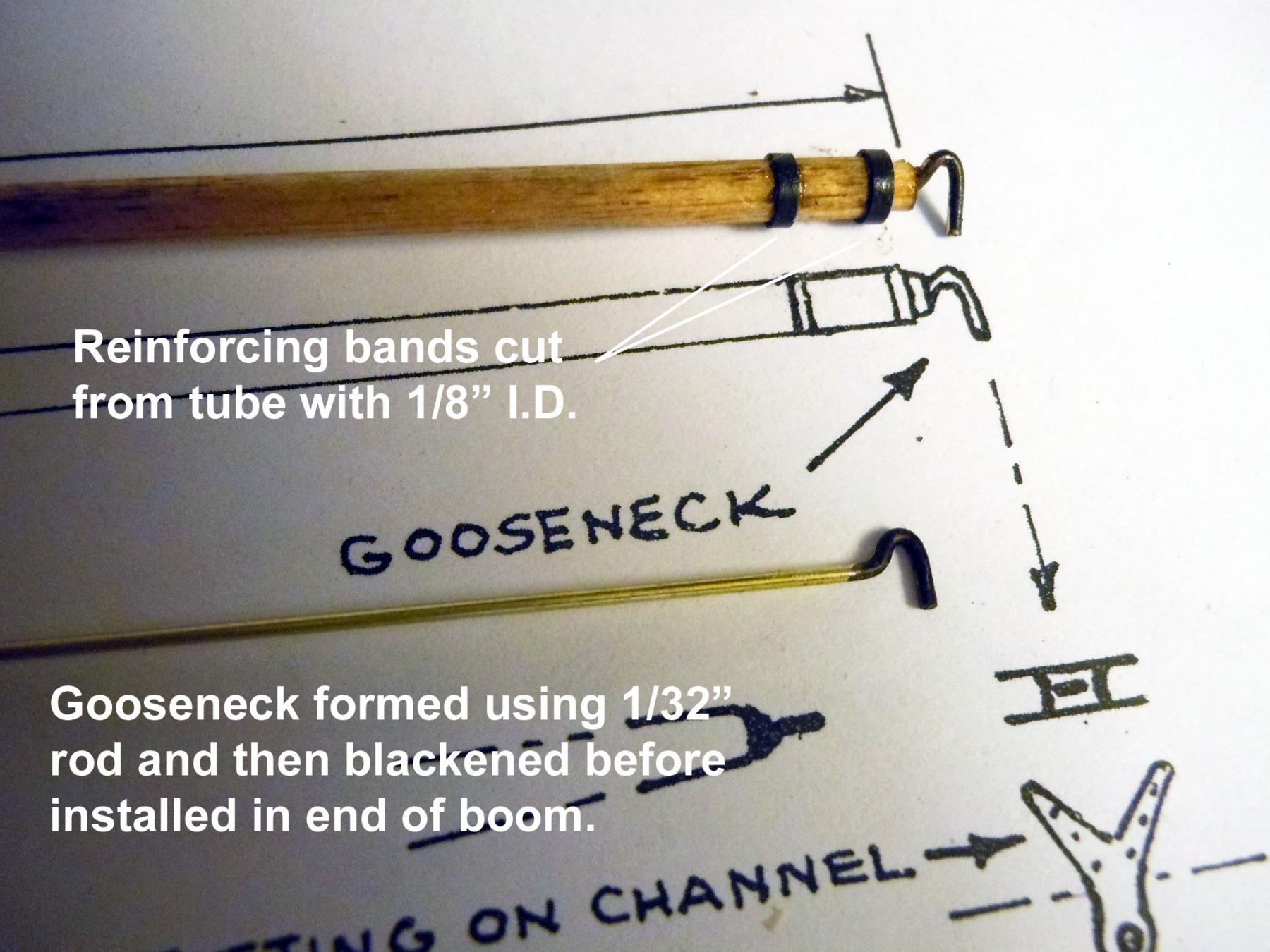
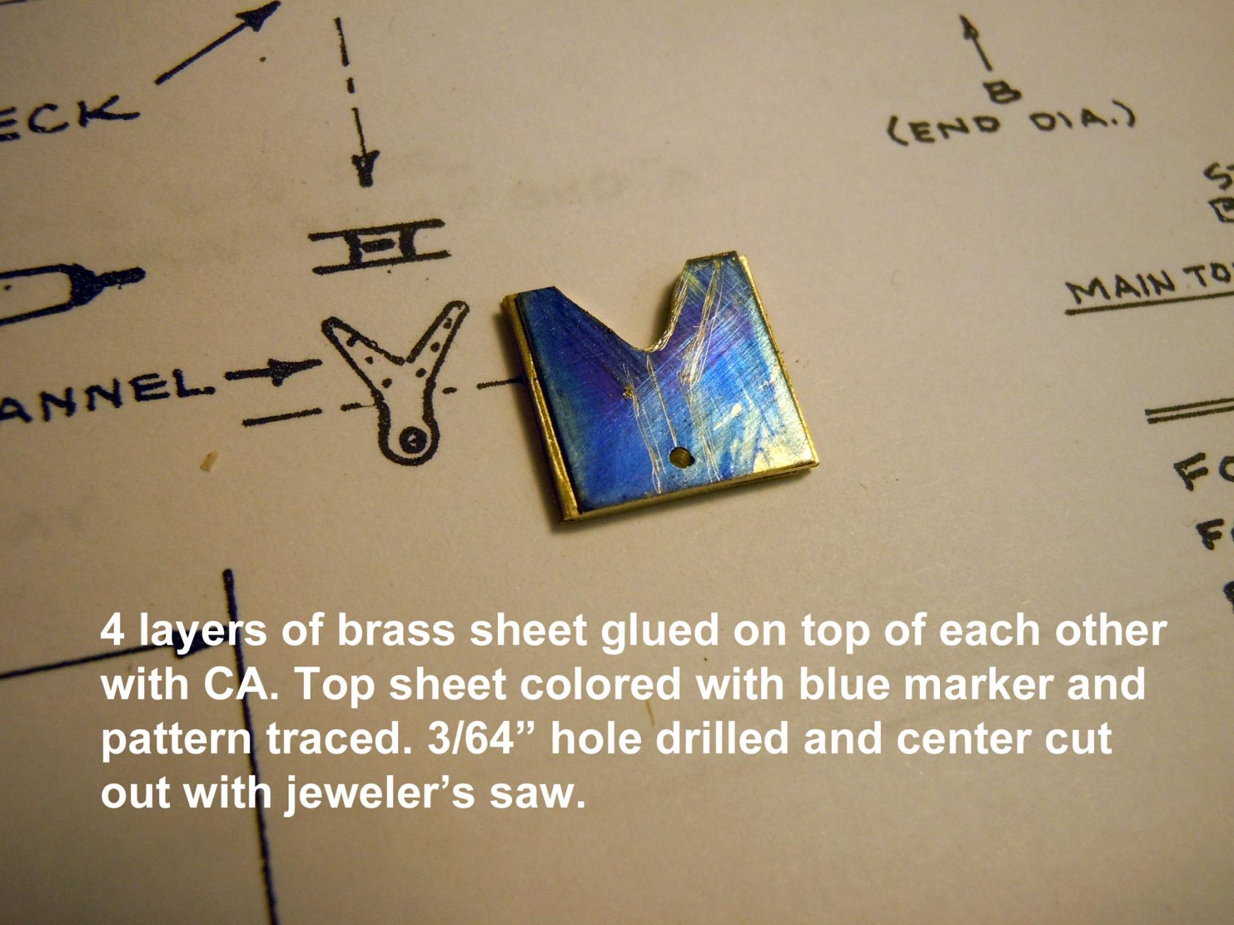
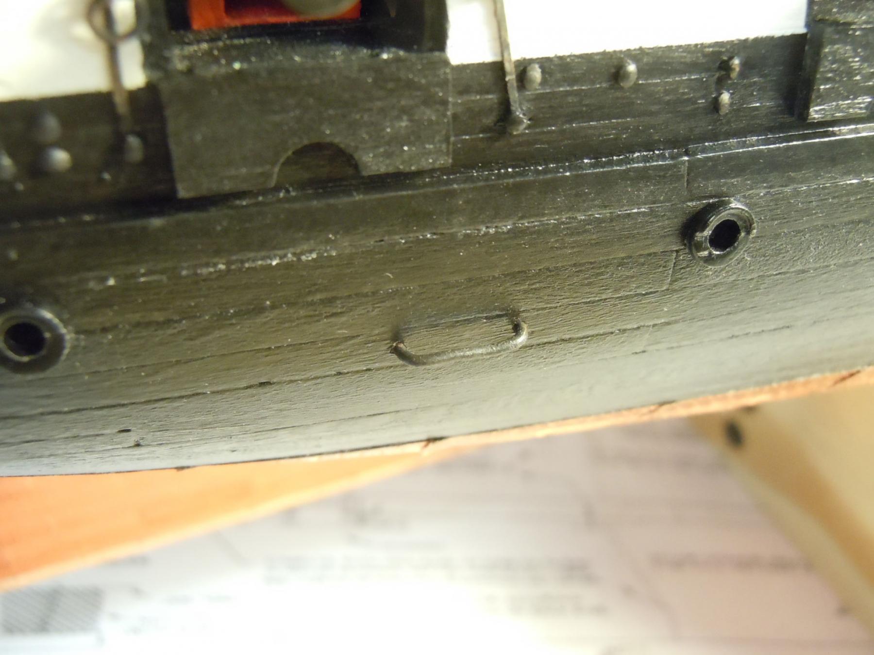
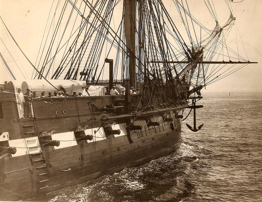
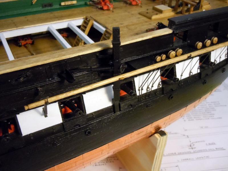
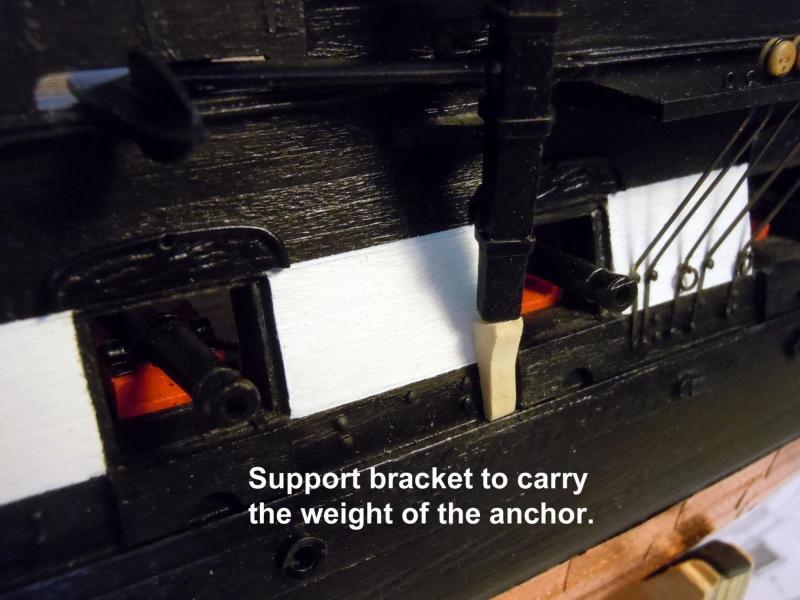
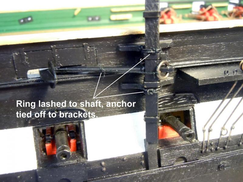
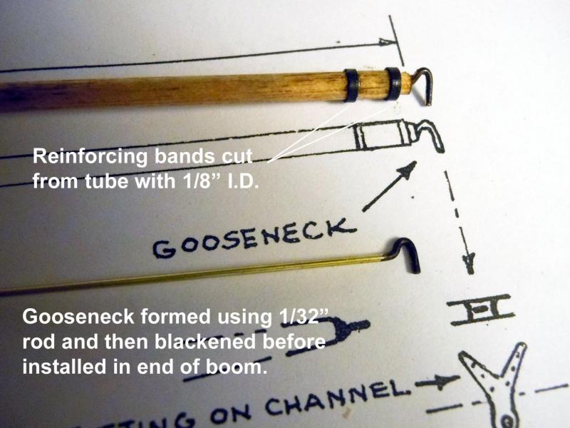
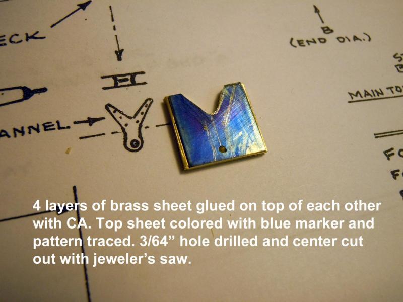
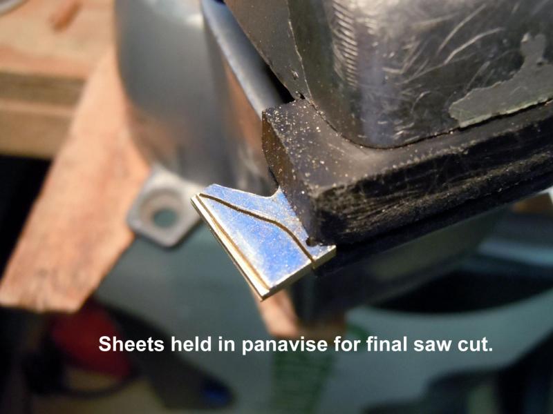
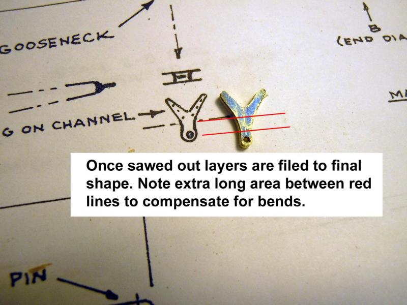
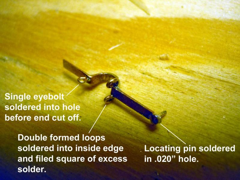
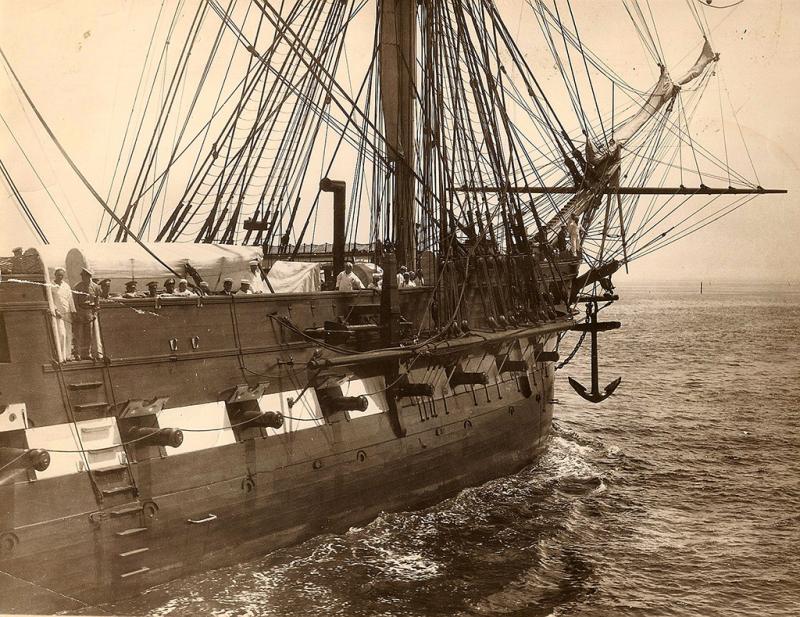
Michael, thank you for your kind comments. Yes we do live in a great location with mild weather year around. I have moved on to the studding sail booms and realized that I had to locate the anchor in place first. In looking at how the anchor was rigged on the plans it seemed odd that all the weight was carried by the eyebolts. I then checked the above photo by zooming in and confirmed that there is indeed a support bracket that the anchor rested upon. Next I tapered the studding booms and added the reinforcement rings and gooseneck hooks. I then fabricated the first and second support brackets that are once in place will establish the boom location in order to fabricate the third bracket. Following is a sequence showing how I made them and will let the pictures speak for themselves. Now on to making the third and a little more complicated brackets.


-
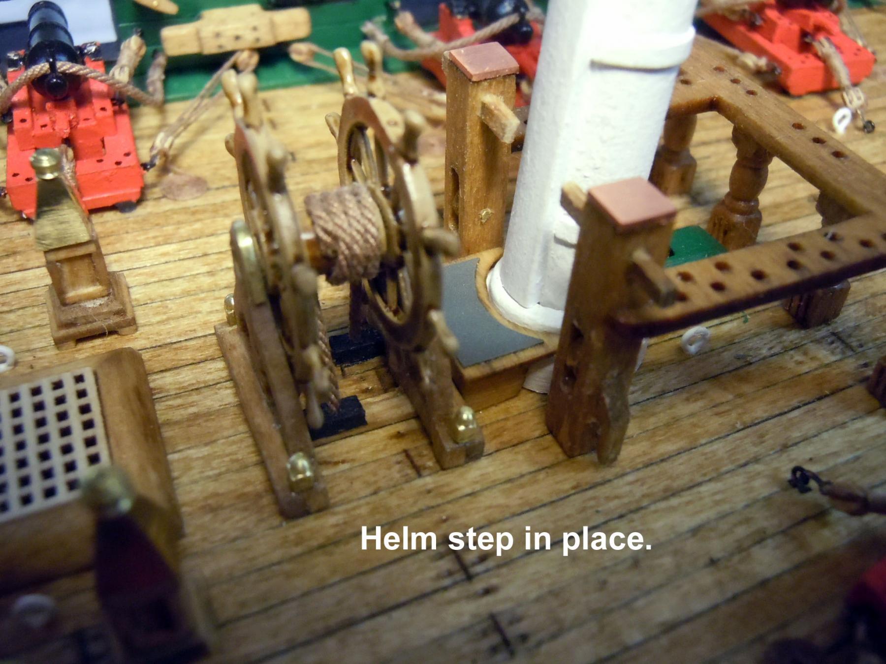
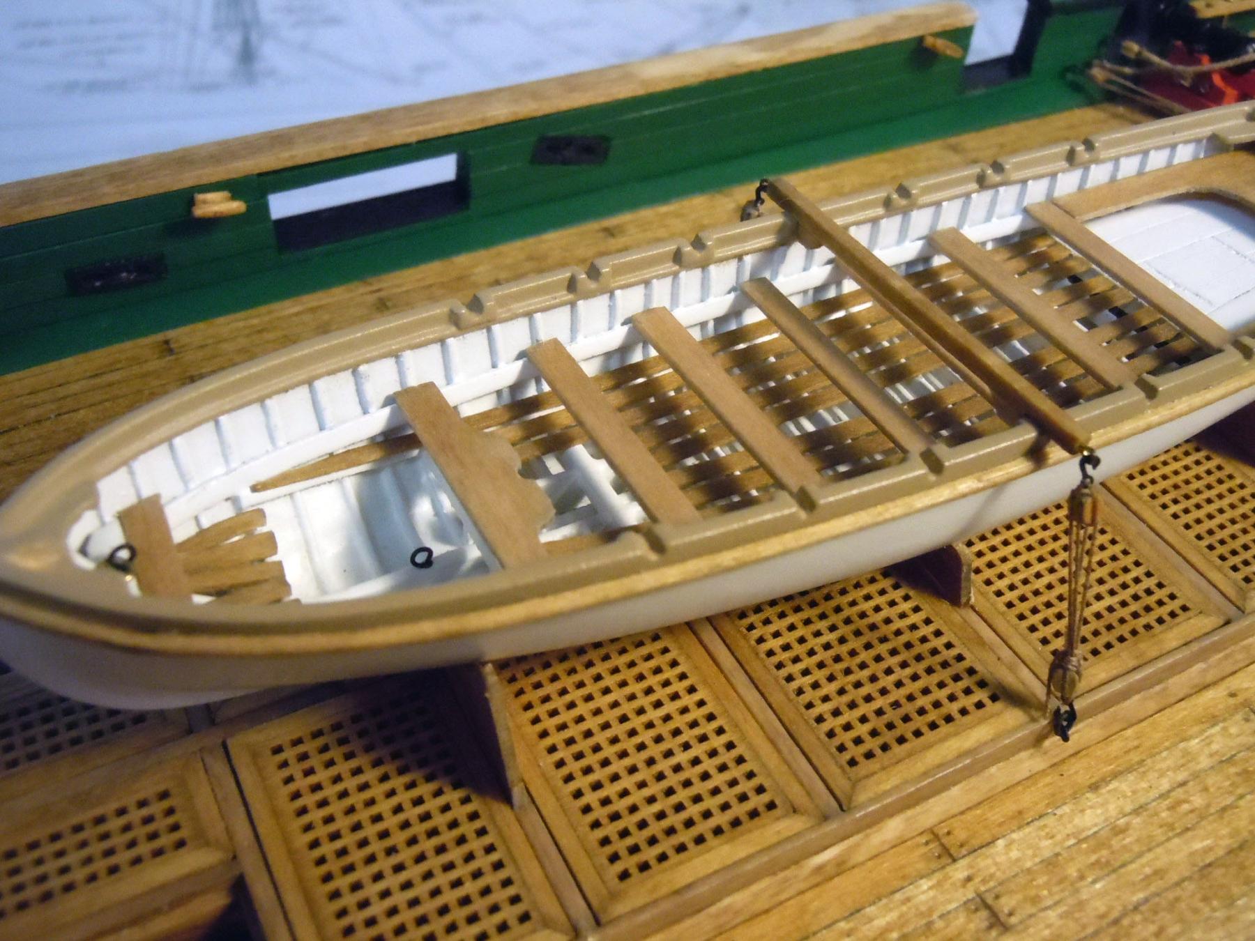
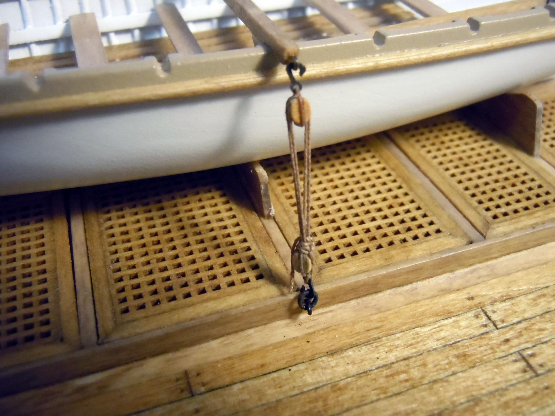
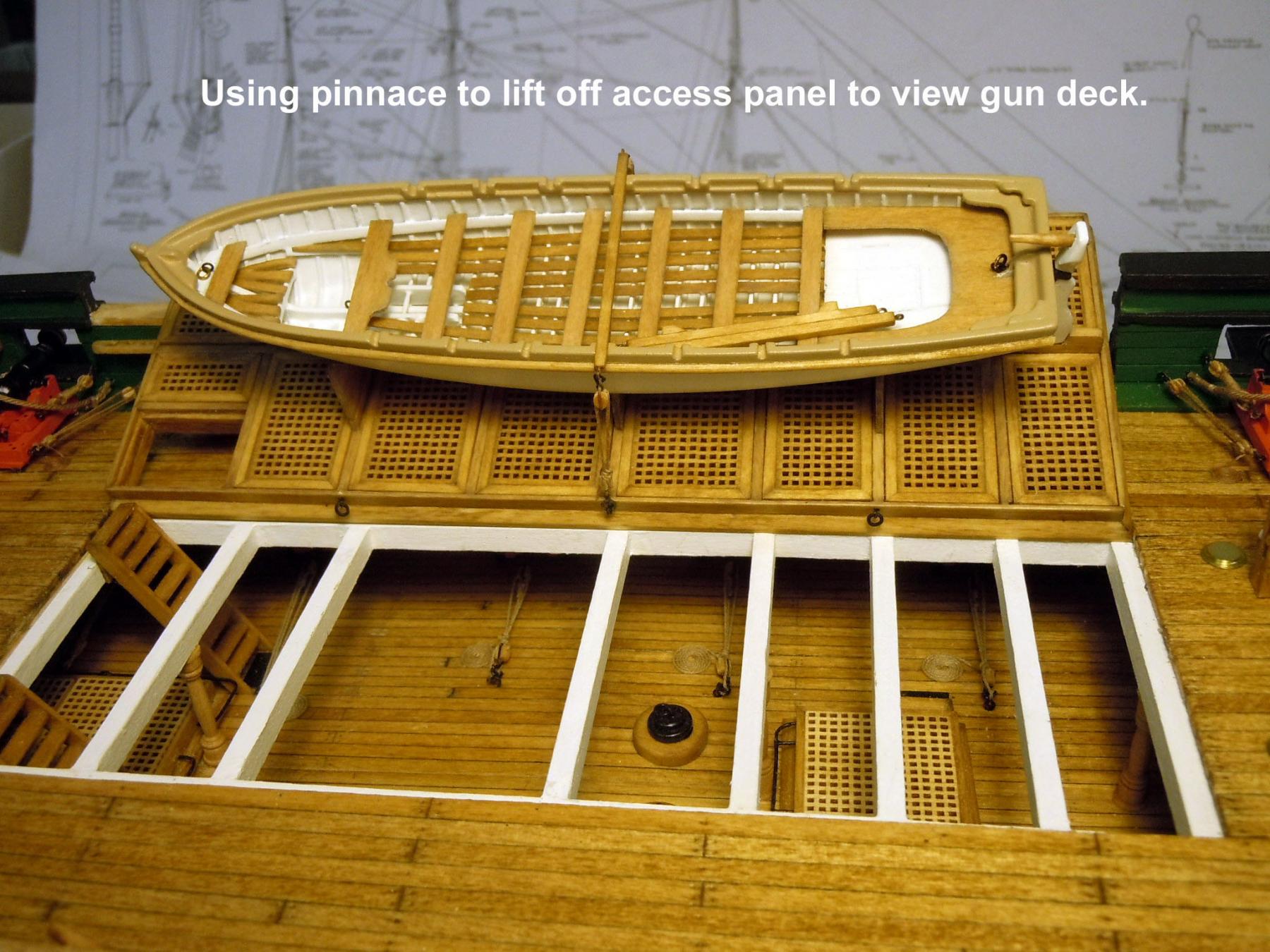
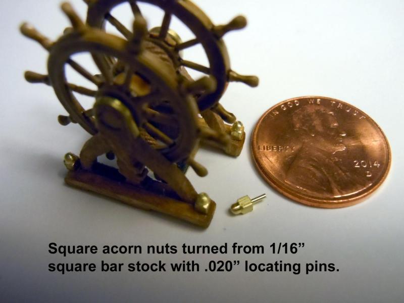
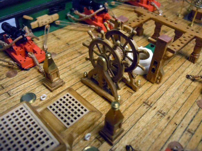
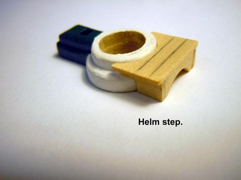
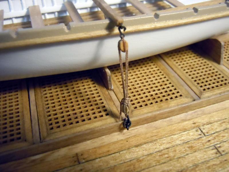
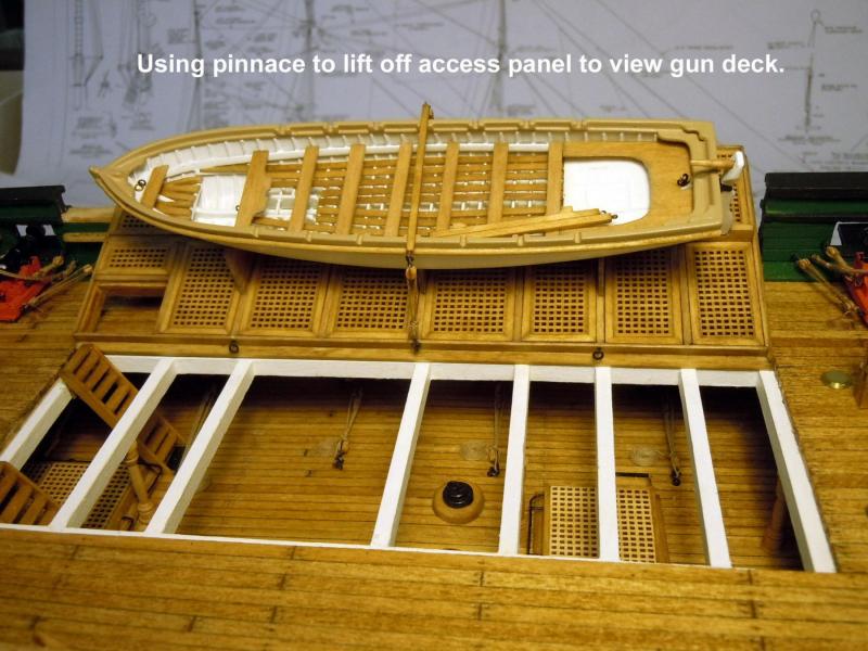
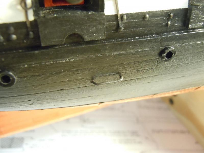
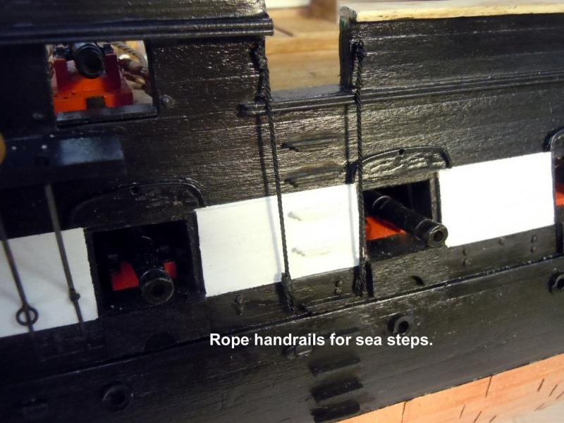
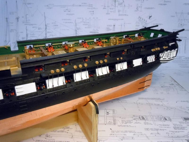
Finishing up a few more details on the spar deck and hull. I am trying to identify things to be completed before starting the mast installations. Of course just when you think you have everything you see something else to be done. Here are acorn nuts I turned for the helm as well as the helm step that can be seen in some pictures. I think the acorn nuts would have been square rather than hexagon which would have been a more recent nut design. Here is the center tie down for the pinnace that will be used when the ship is completed to see the gun deck when lifted by the pinnace. I am just doing the center one for now since the mast and oars need to be added. Next I added the six mooring staples and then using a period photo for reference I added the rope hand rail for the sea steps. Now to see what else besides the main mast stay anchor points and rear backing plates for the exterior stern rings (perhaps for towing?) that I may have overlooked. Then on to the storage brackets for the sailing booms that can also be seen in the picture above. A side note in this picture is the taller and straight smoke stack versus the shorter tapered one that is on the plans.


-
Post as many pictures as you can please!
-
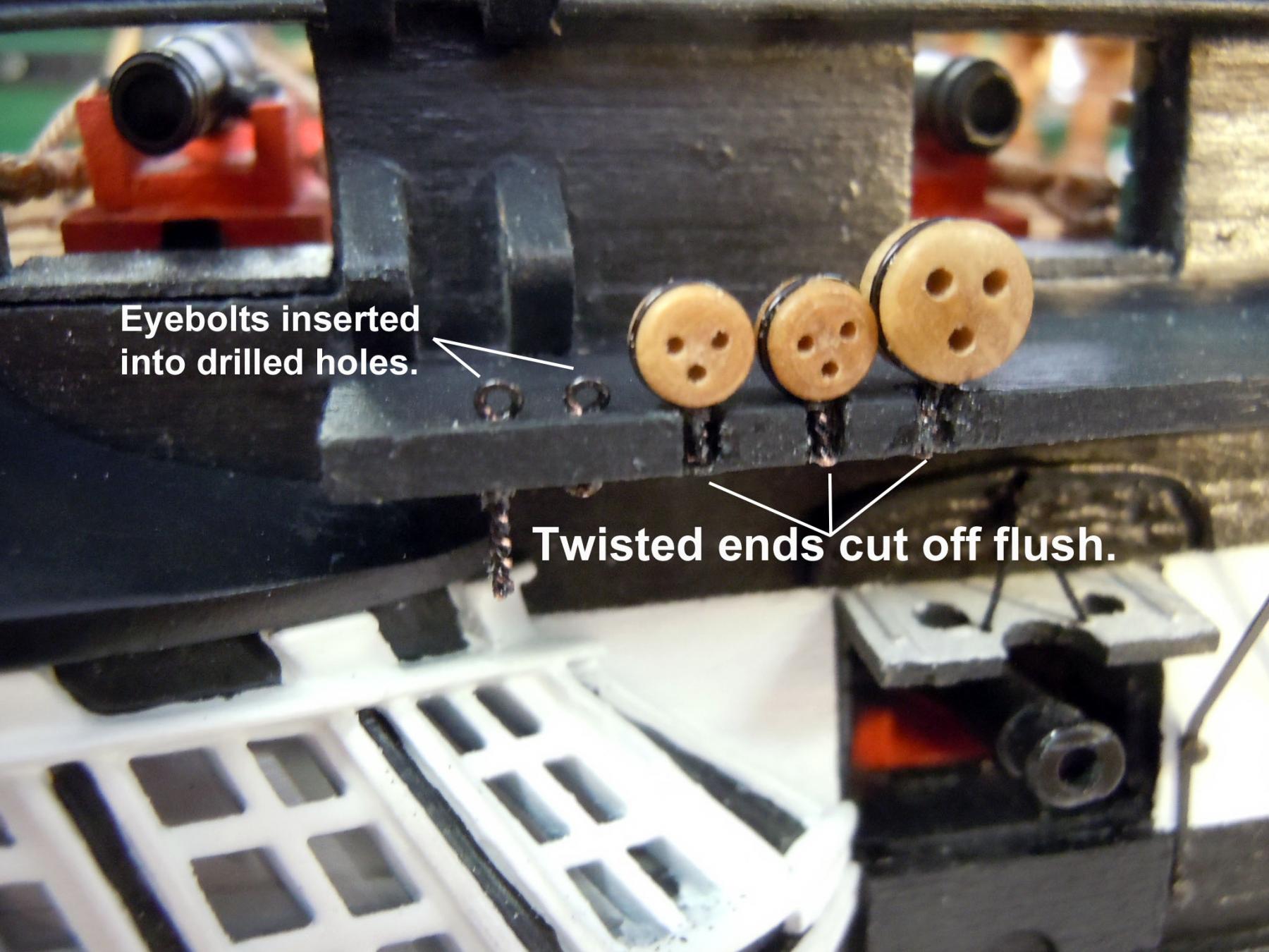
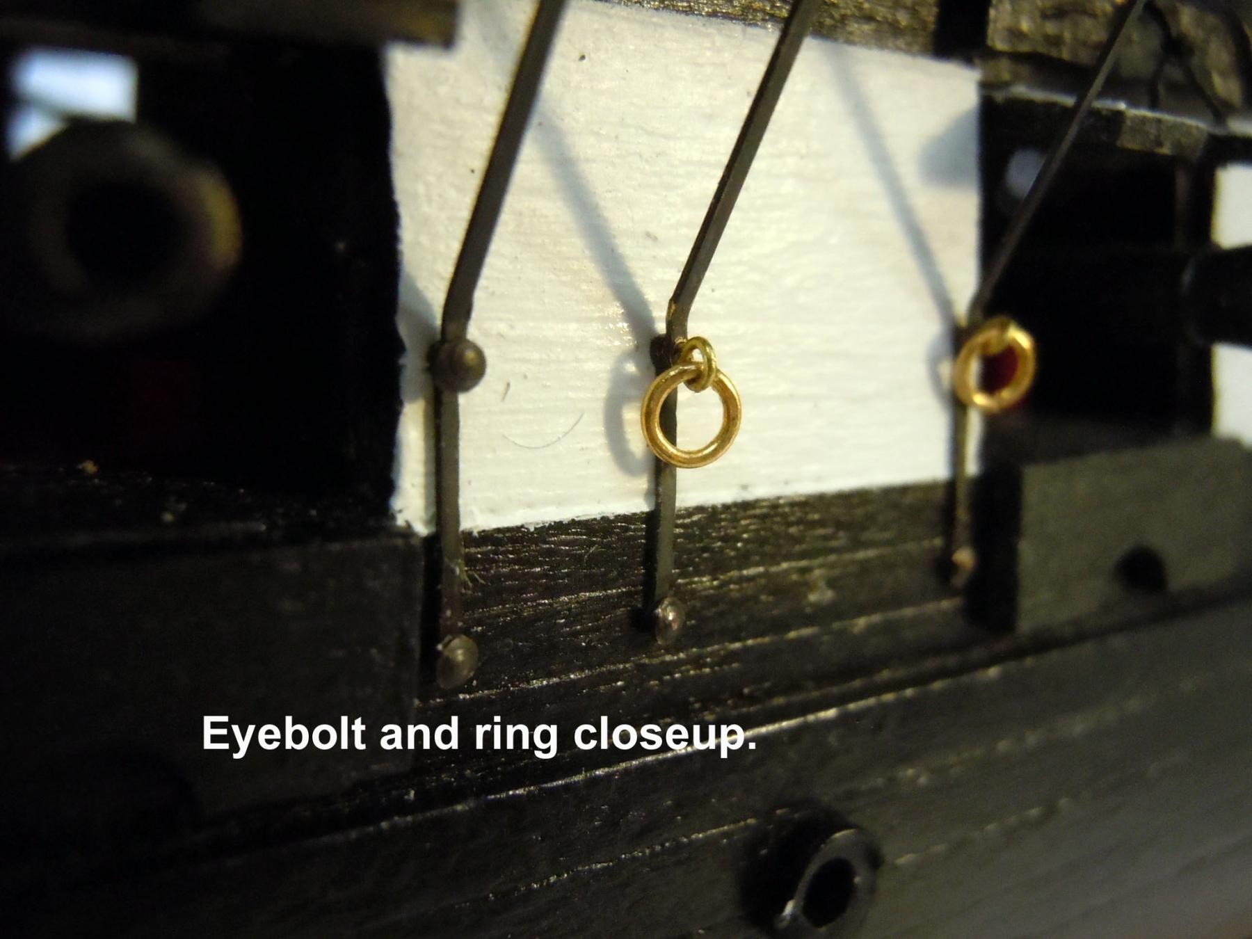
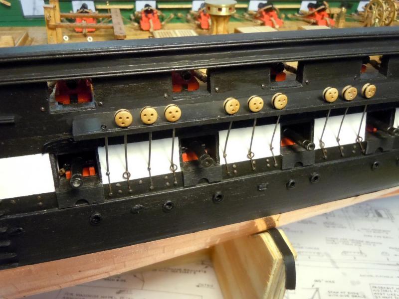
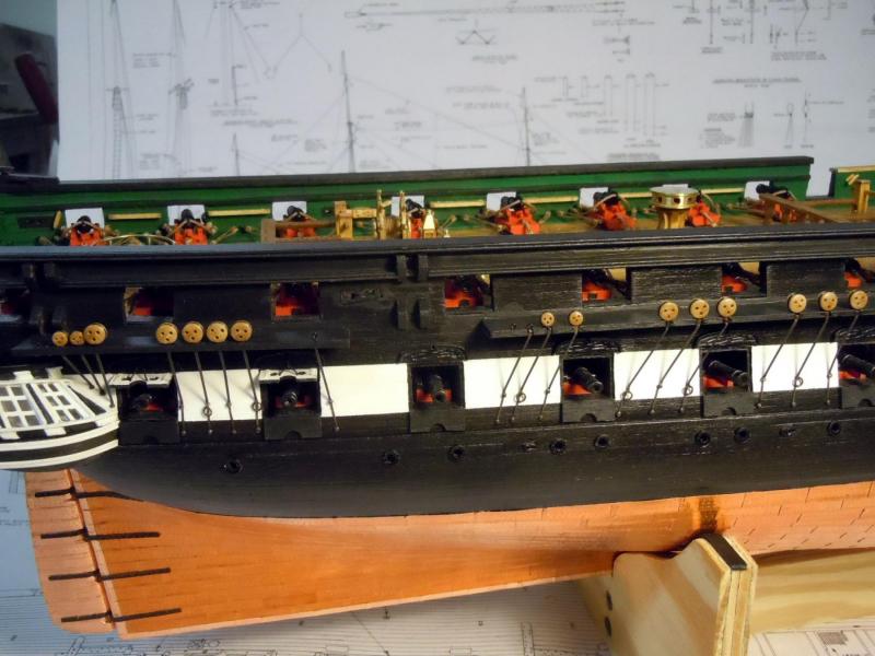
Finished up the chainplates and then added about 180 gun breech line bolts to the exterior of the hull. Now to touch up some paint details; then glue the deck furniture in place and add some of the balance of the hull details. Not sure if I should paint the deadeyes black or not; they look nice as a bright finish. Here are a couple of images of the finished chainplates and breech line bolts. Now back at it.
-
Tom, Thanks and yes you are correct; I will be glad when they are done. The greatest challenge is enlarging the holes for the nails. I make the ring eyebolts using 34 gauge brass wire so they fit nicely without enlarging.
-
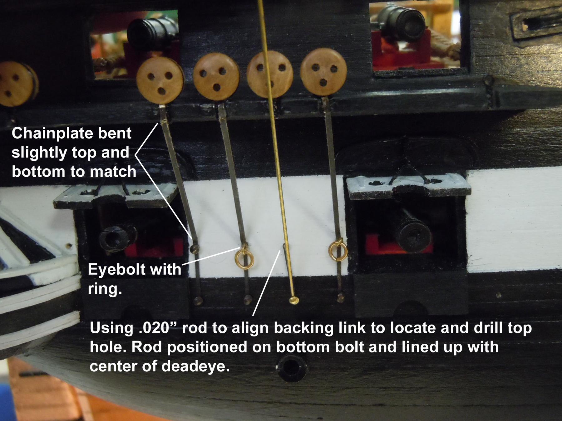
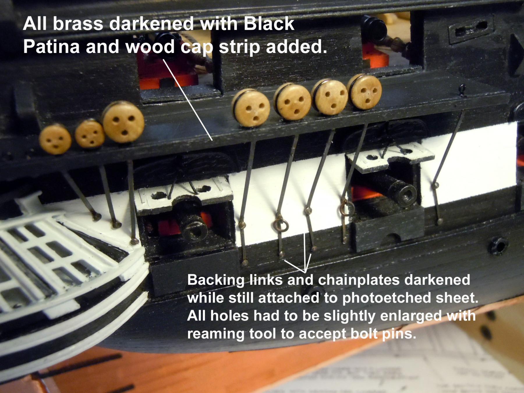
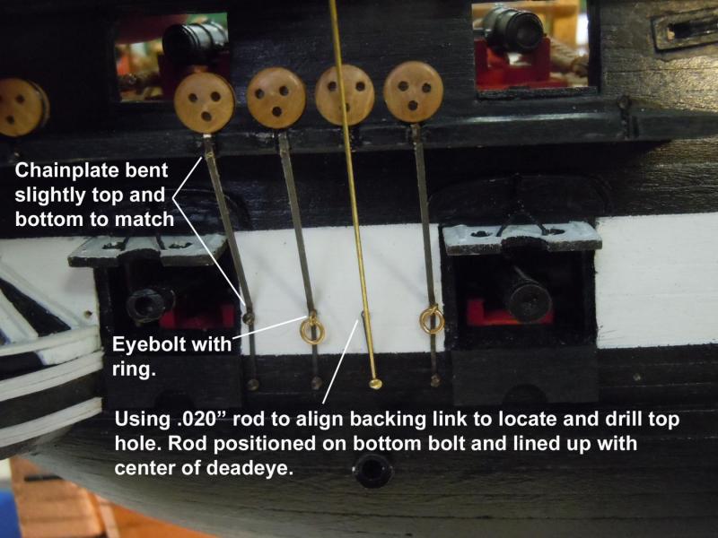
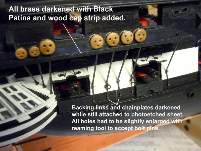
Back at it after helping wife and getting my NRG presentation on a CD mailed off. I checked the chain plate photo-etched parts and again the holes did not match the nails supplied. I darkened all the part sheets with Black Patina both sides and once set started to very carefully enlarge the holes with a small ream to fit the nails. Would have been great if the kit builder had checked these first. I also stropped all the deadeyes and twisted the number of eyebolts needed. All was slow tedious fussy work. The eyebolts were twisted using a #76 (.020") drill bit shank and 26 gauge black beading wire. Also keep the two hole in the deadeye up as best as possible given the hole locations on them. Working off the plans I transferred the bottom backing link hole locations and drilled them with a .020" drill bit to receive the nails. Added the backing link to the hole and used a brass rod to align the link to drill the top hole location. Once drilled the chain plate was added, marked, cut and bent to fit it's location against the eyebolt or deadeye. Keep in mind that the top hole of the backing link needs a eyebolt to hold a ring instead of a nail. Again using the plans for the location of these rings.Once one section was competed the painted wood strip cap was added. Here is a sequence of photos showing the process I am using. Now to continue on with adding the chainplates.


-
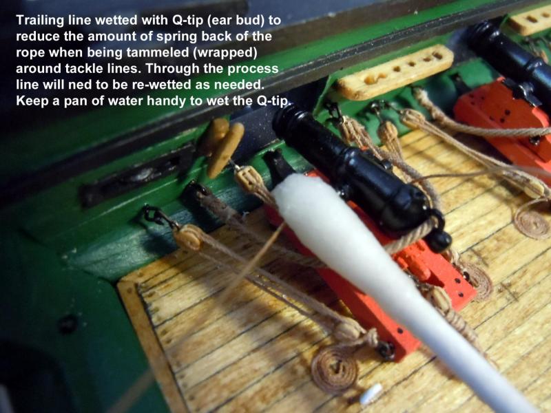
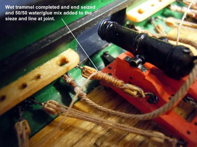
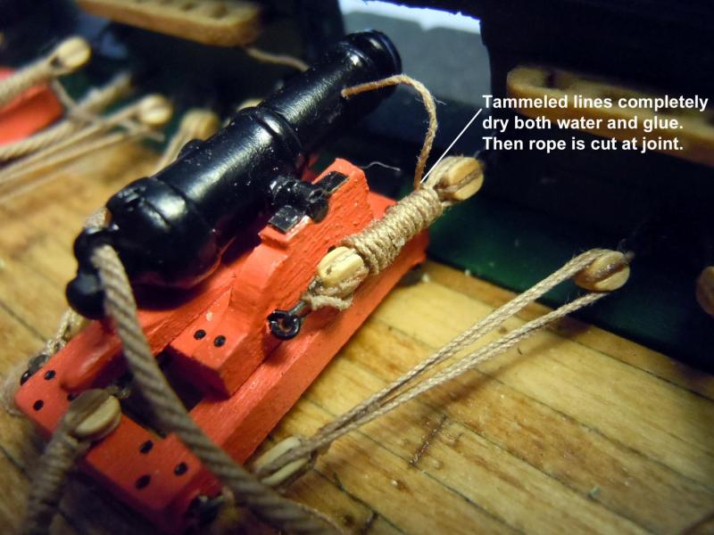
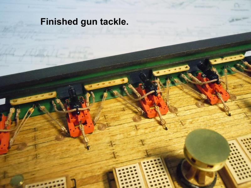
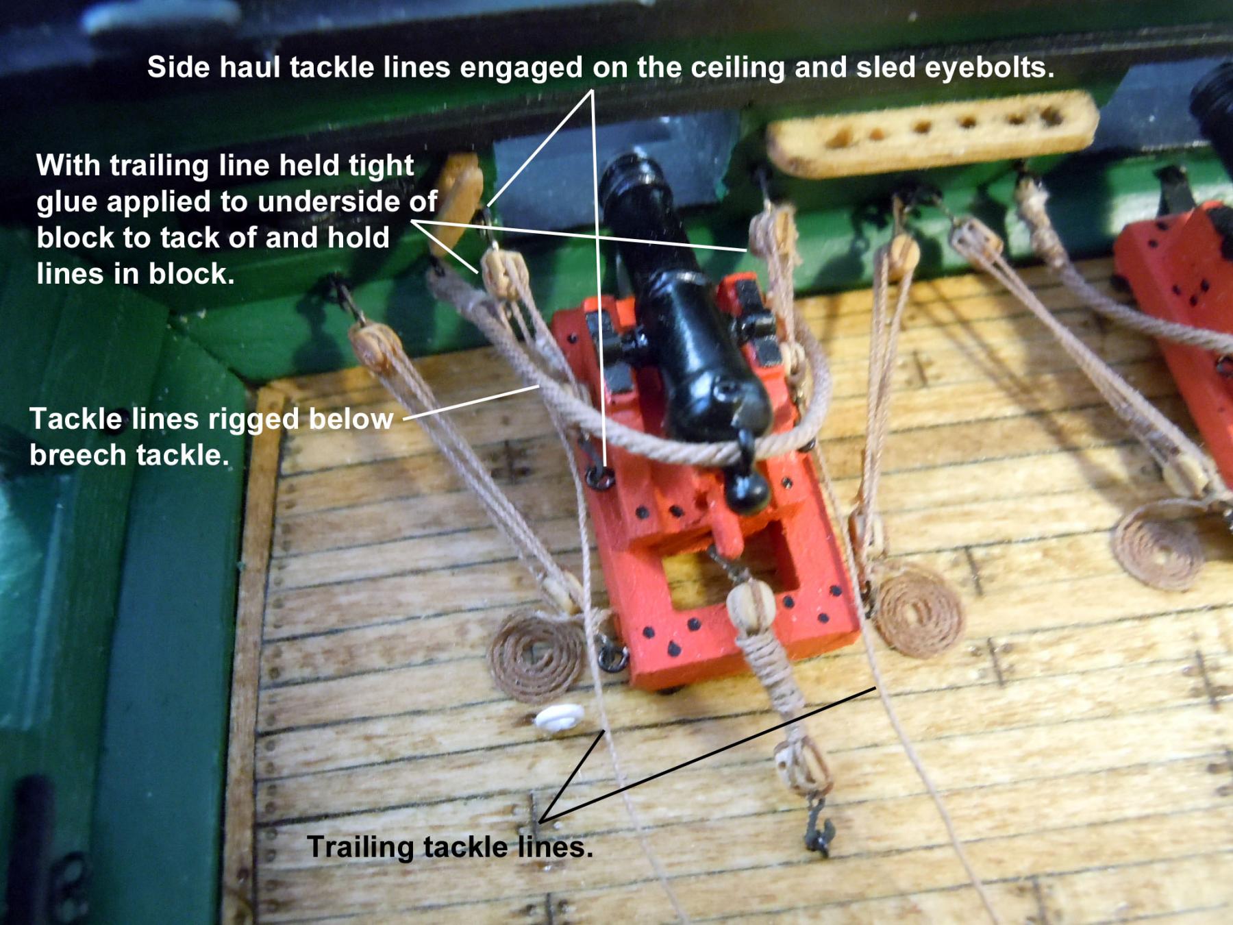
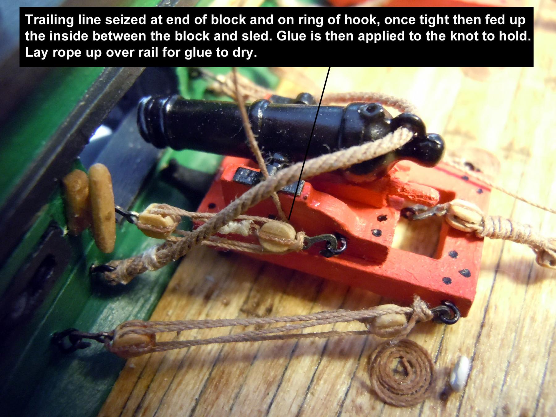
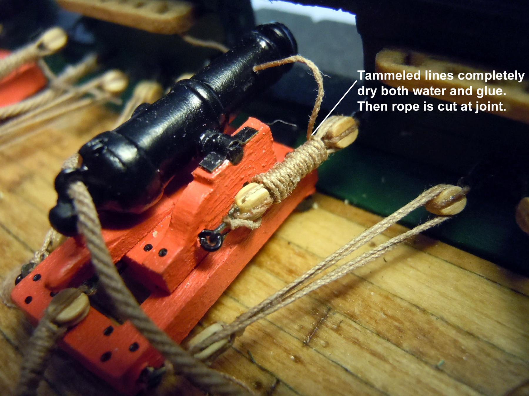
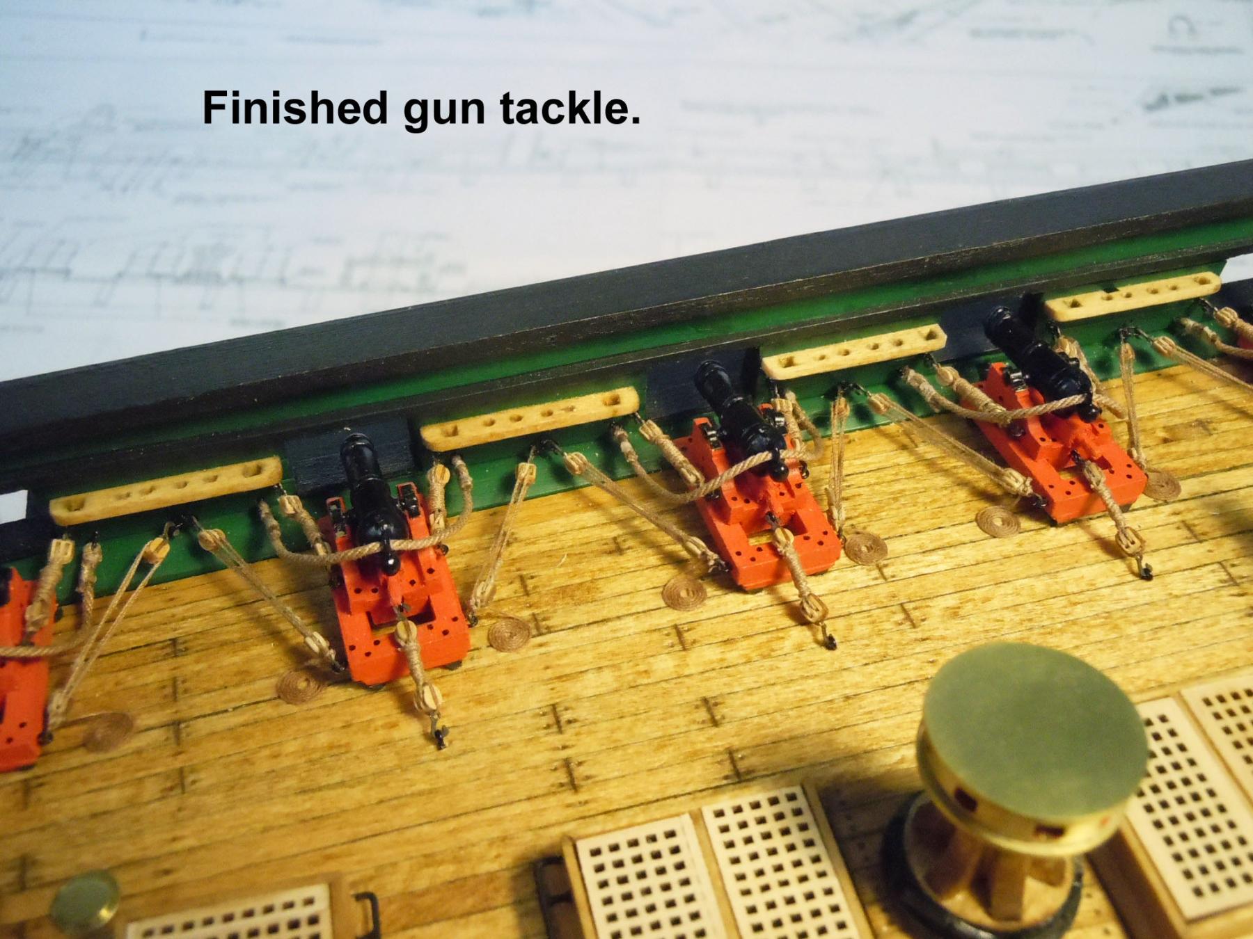
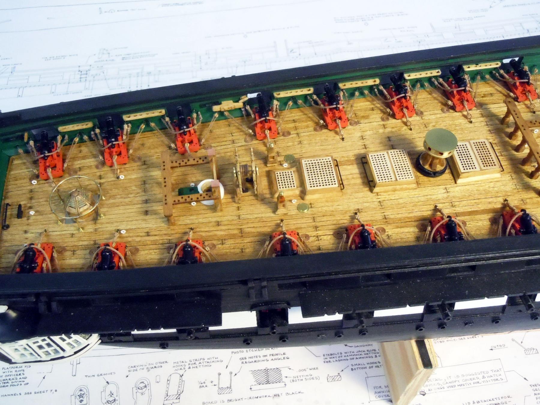
I finally have finished up trammeling the side tackle lines for the carronades. This was as I anticipated a slow tedious process; but a very rewarding one with great results. I thought I would share some tips and tricks of how I did them for the benefit of some who may also want to do them. First I was using Chuck's 3mm hooks, 3/32" blocks and .008" rope line. The blocks were drilled with #76 drill bit for easier rigging. Once hooked to the ceiling wall and sled the real trick was wetting the rope line with a Q-tip (ear bud) and keeping the line wet as it was trammeled. The use of 50/50 mix of glue and water was used to hold line in blocks or hold knots. The 50/50 soaks in better with the wet rope; however may require a second application prior to cutting the rope, test hold first. The end of the rope was fed forward to the gun port and pulled up and back around the lines being wrapped. Use a gentle touch when wrapping the rope and snug up rather than pull tight. Once dry the wrap can be adjusted slightly to make even if not. I left my breech lines unglued and it would be better not to glue the large cleats or belaying pin racks in place until the guns are rigged. I was able to do them with these in place, but it would be much easier with out them in the way. A picture is worth a thousand words so here are a few that may better help. Next on to the chain plates. This weekend I will be helping the wife with her craft show again. So no work until next week.