HOLIDAY DONATION DRIVE - SUPPORT MSW - DO YOUR PART TO KEEP THIS GREAT FORUM GOING! (Only 13 donations so far - C'mon guys!)
×


xken
-
Posts
841 -
Joined
-
Last visited
Content Type
Profiles
Forums
Gallery
Events
Everything posted by xken
-
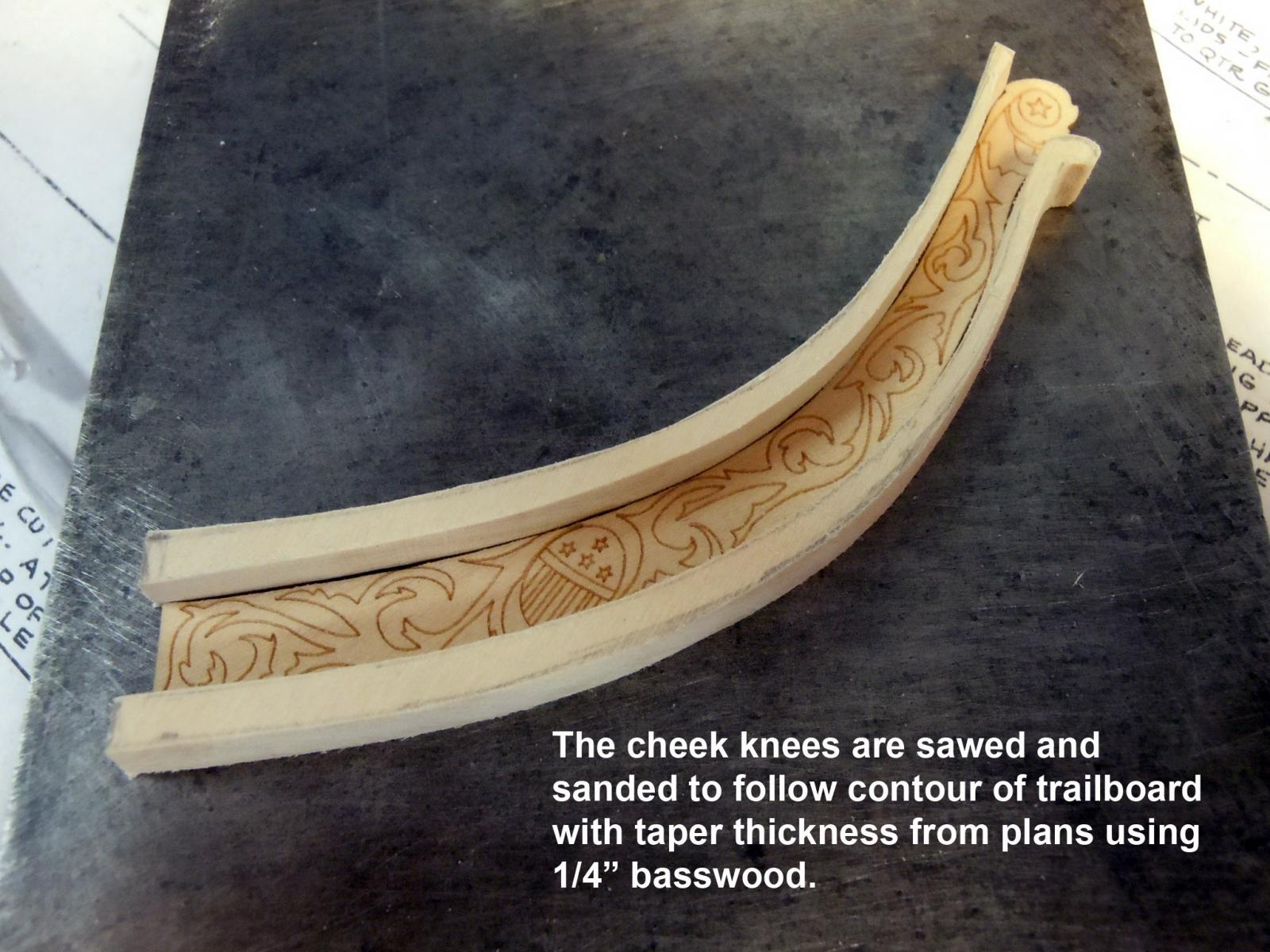
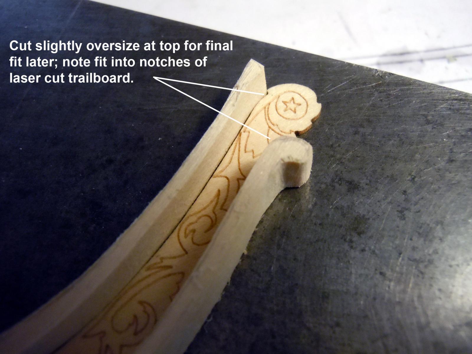
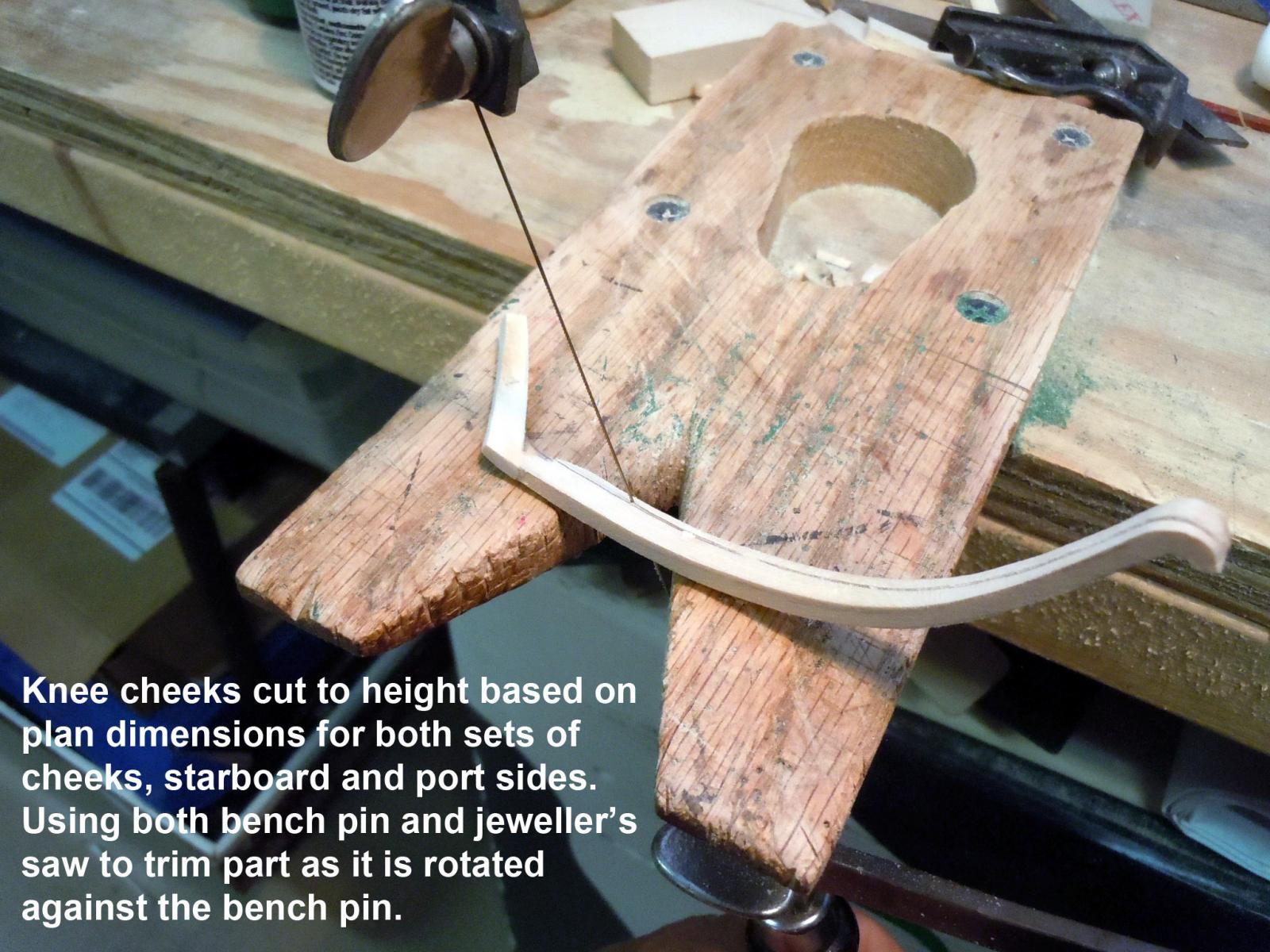
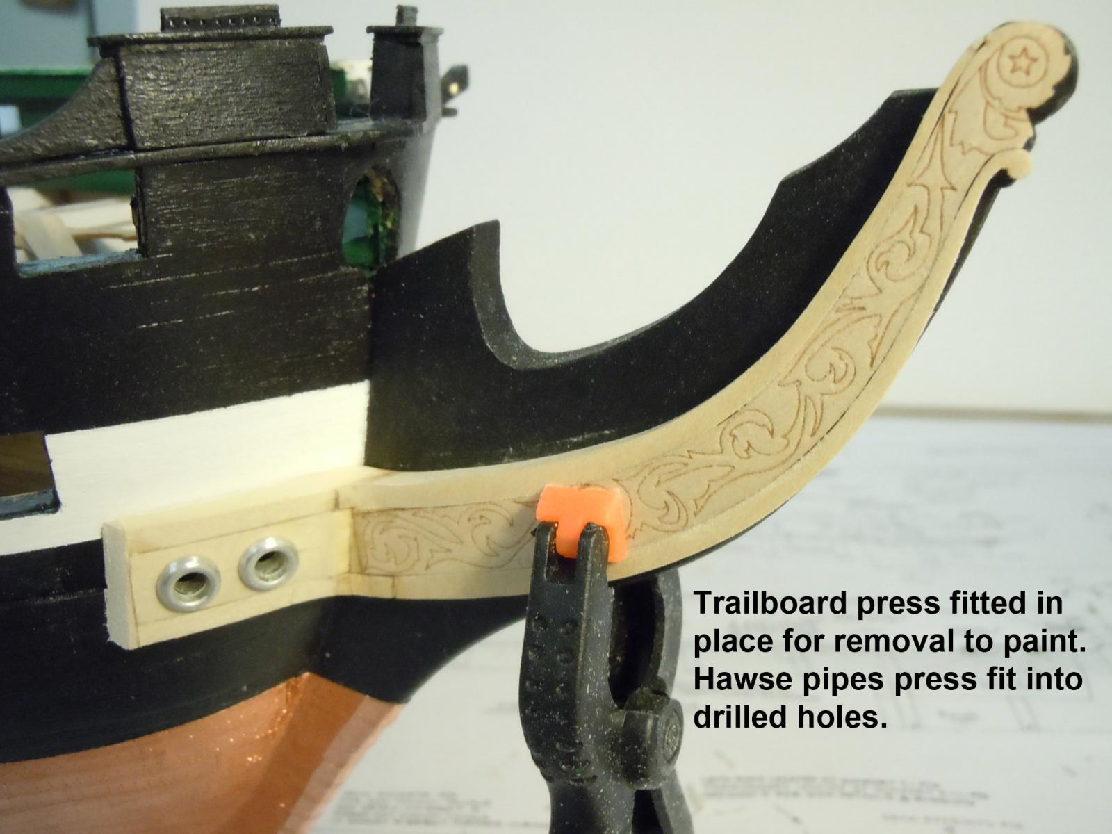
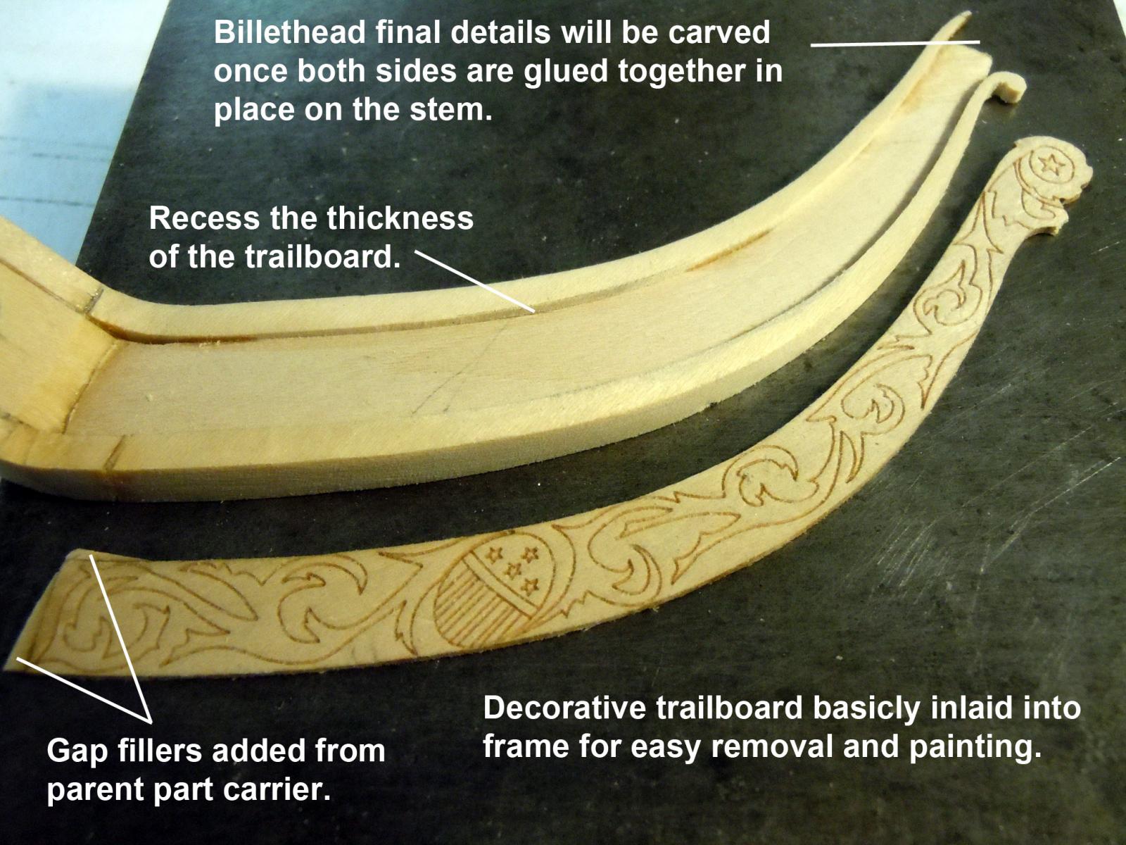
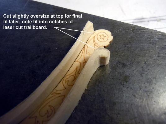
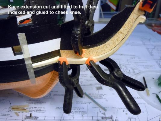
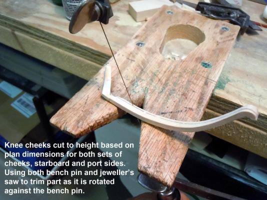
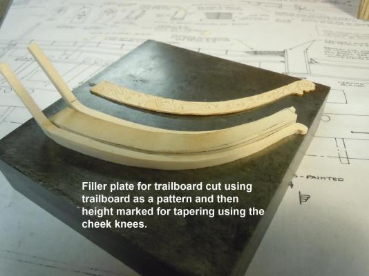
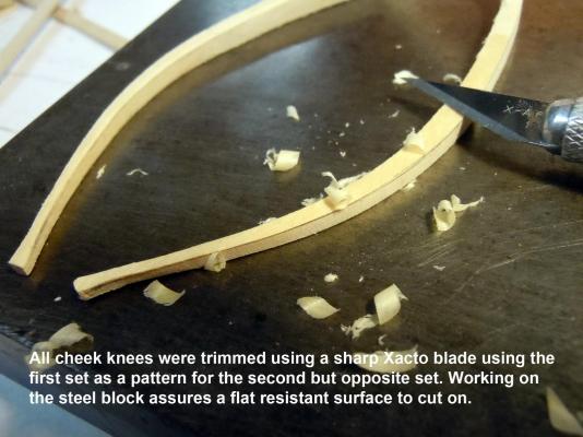
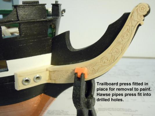
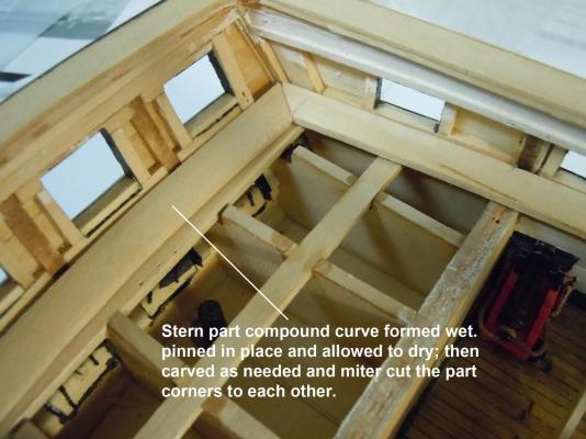
 I did some research of photos of the restored ship and what historical detail photos I could find and realized that the plans for whatever reason do not show that the trailboard and hawse pipes are on raised surfaces and the trailboard tapers in thickness from the hawse joint to the billet head. I then decided to build as the real ship is versus the plans which I am quickly losing faith in. One other side note for those on computers and have an I-pad I discovered that I cannot zoom in on photos with my PC; however, with the I-pad I can and based on the resolution of the photos details in some are quite sharp much to my surprise. My I-pad is now my best friend for detail research and is now residing on an adjacent desk. Here is a sequence of how I have constructed the trailboard framing. These were much easier to do once I realized what had to be done based on photos rather than the plans. I used 1/4" and 3/16" thick sheet basswood with parts cut using the jeweler's saw on the bench pin and carving with a sharp Xacto blade. One word of caution is to pay attention to the layout of parts to follow the wood grain in thin sections for strength. Also I sand and carve on the steel block, usually at the edges for finger clearance and to keep the blade parallel to the steel surface as reference when cutting the taper of the knees and filler block. Now to finish up both sides.

-
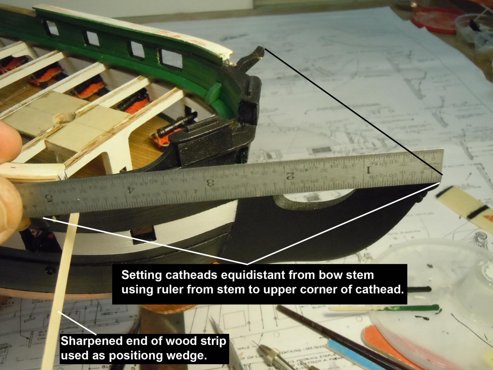
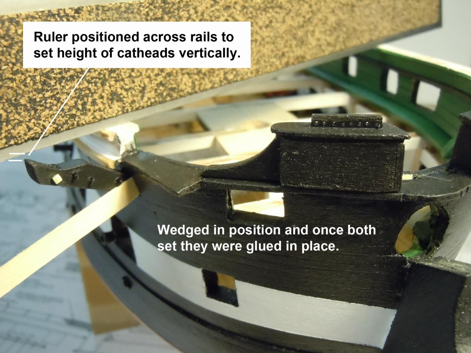
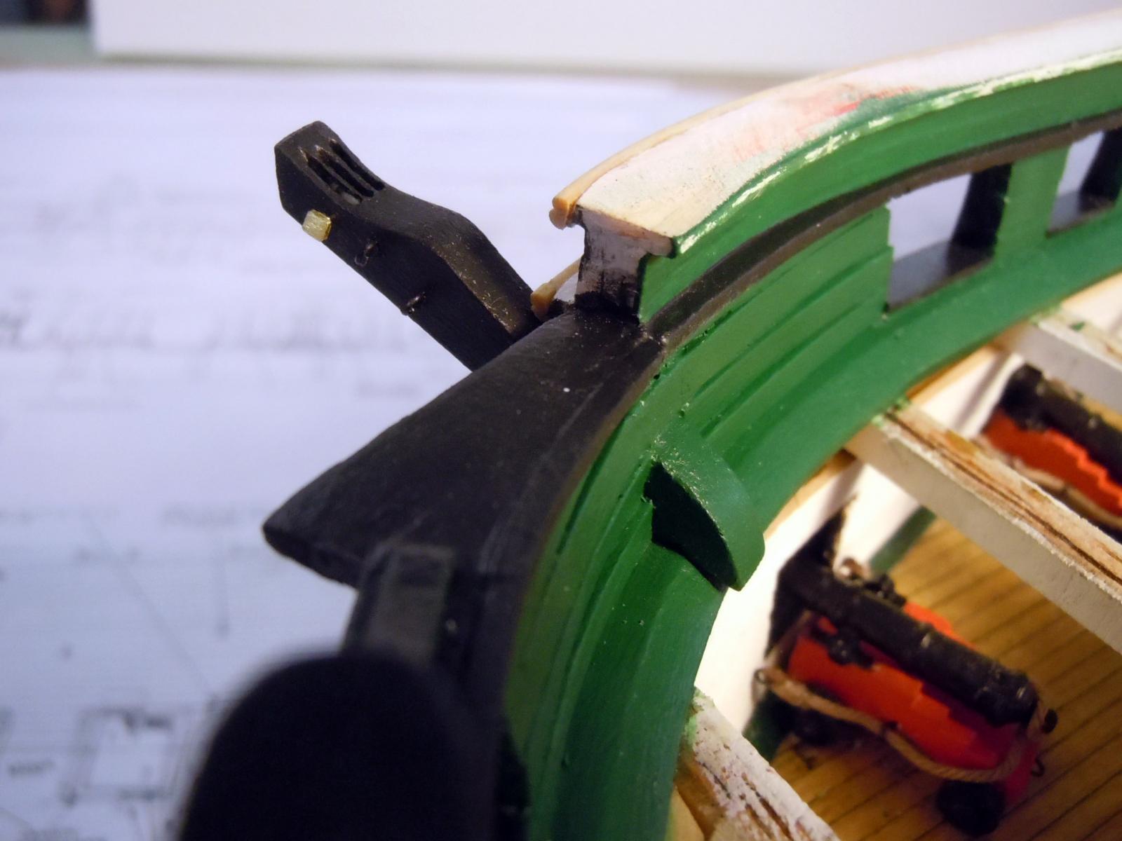
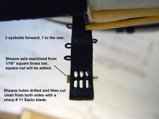
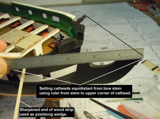
As I pondered my next step in addressing the head rail structure at the bow I quickly realized that careful installing and positioning of the cat heads was needed. First I sanded then drilled the holes for the sheaves at the end of the cathead. Once the slots were hand cut they were hardened with CA. and then cleaned again I machined the sheave axle from 1/16" brass bar having a square head. The square nuts are made from 1/64" basswood,drilled and hardened with CA. Then the eyebolts were added and the cathead painted black and green prior to installation. Following are some images of my efforts. The critical part was the installation making sure that both matched each other form the bow stem and rails. Next to sort out the head rail structure now that the cat heads are in place.


-
Kurt, thanks for clearing that up and I am sure in battle action; neatness was not an issue and I am sure that some of these lines were not used at all and stowed.
-
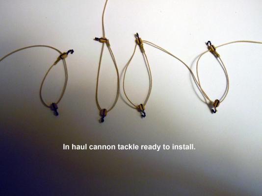
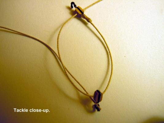
Jonathan, I would concur with the above comments for both running and standing lines on their respective belaying pins. The coils I am showing are for the in haul tackle for the cannons that are hooked to the ring in the middle of the deck and the extra rope in a coil would lay next to the ring with really nothing to hang the rope on. I saw them like this somewhere else and will see if I can find the source again at some point. Perhaps others with more experience and knowledge can comment on this as well. I have also seen the cannons lashed to the ceiling wall which may have been the stowed position when not set up for battle; back to the point of saving space on deck.
-
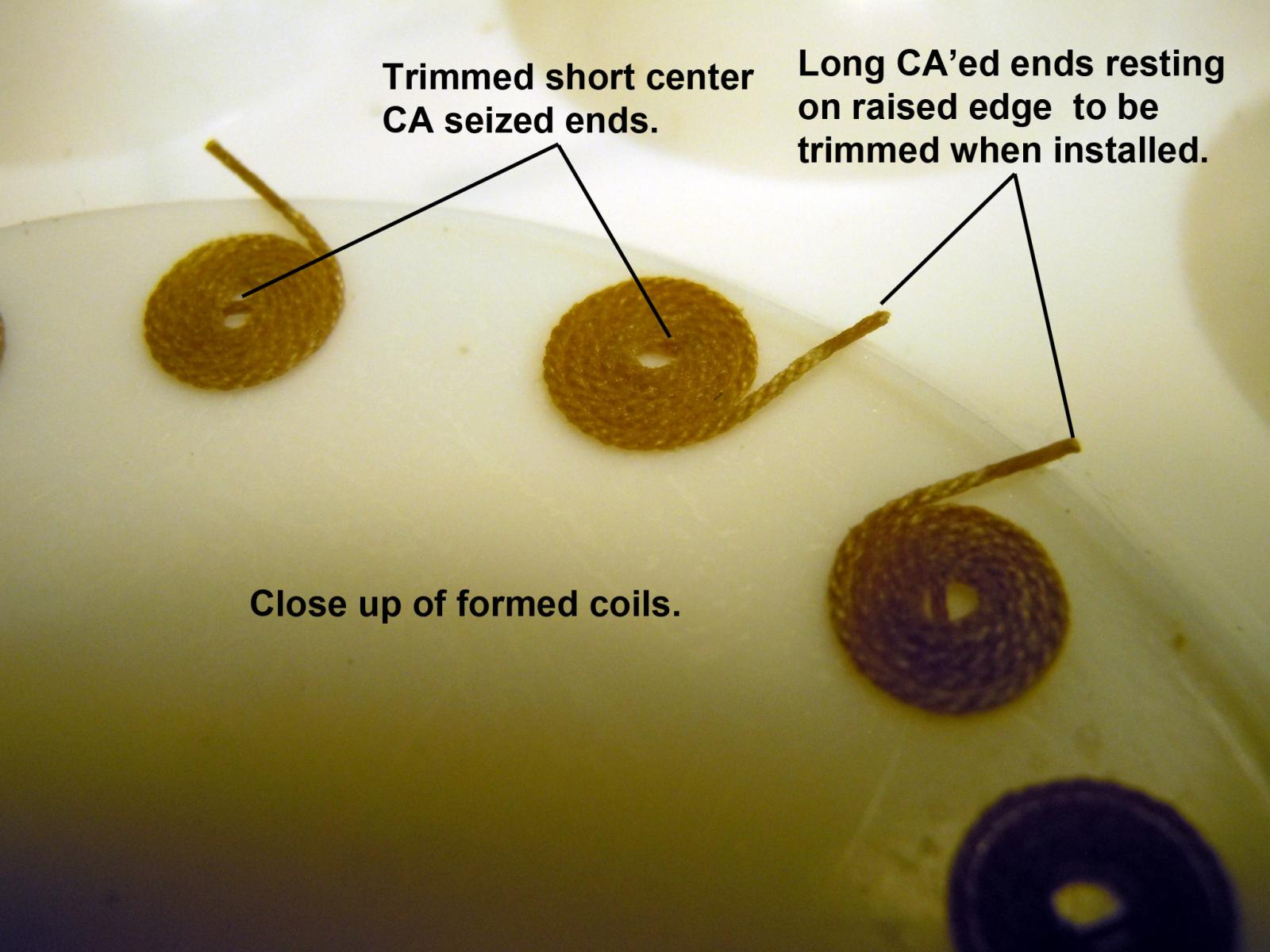
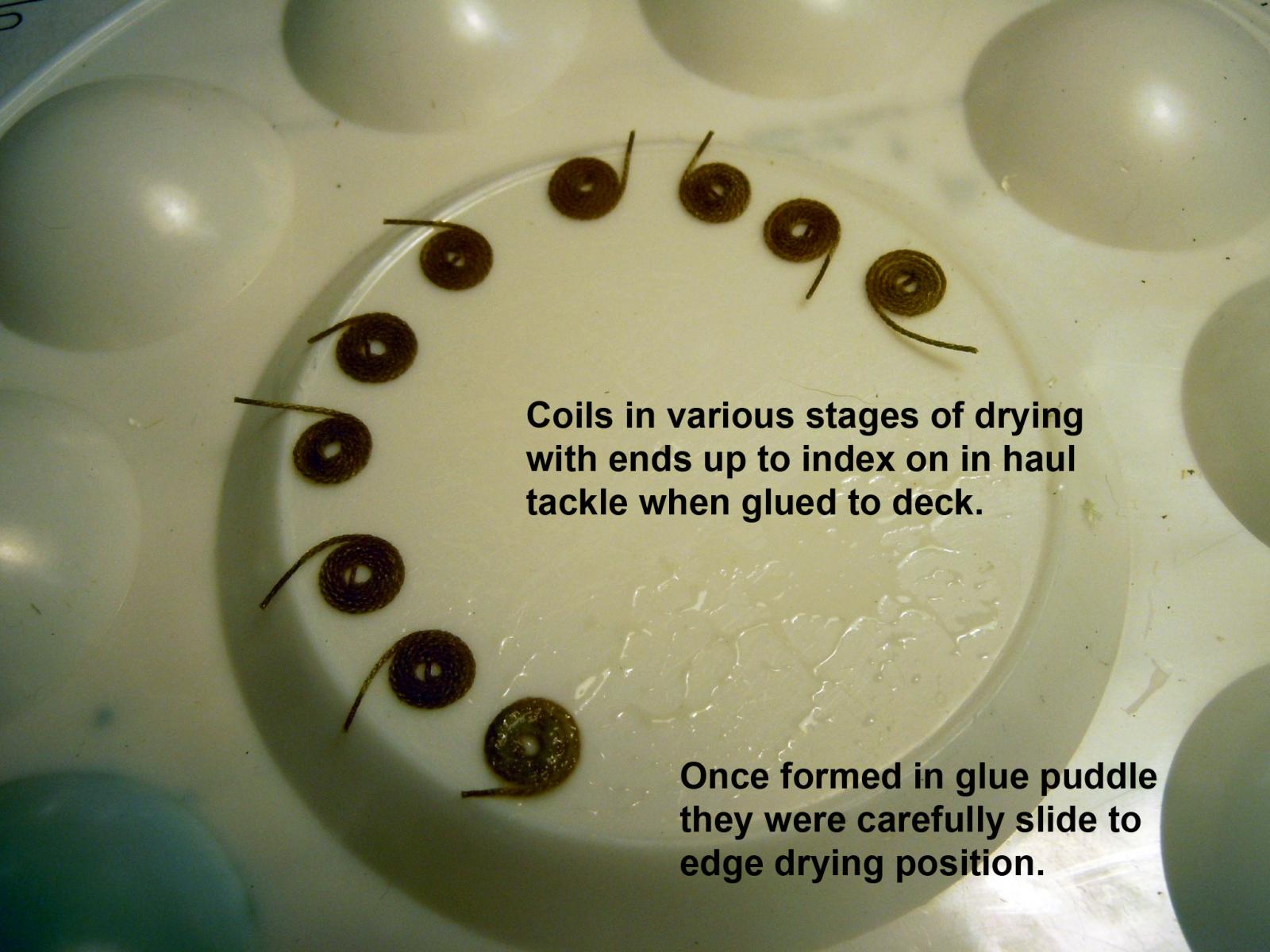
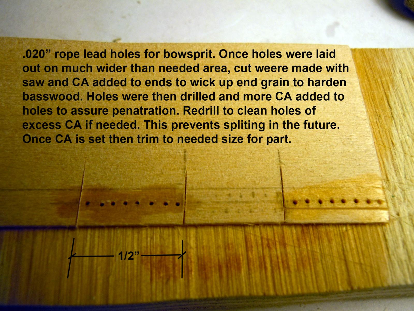
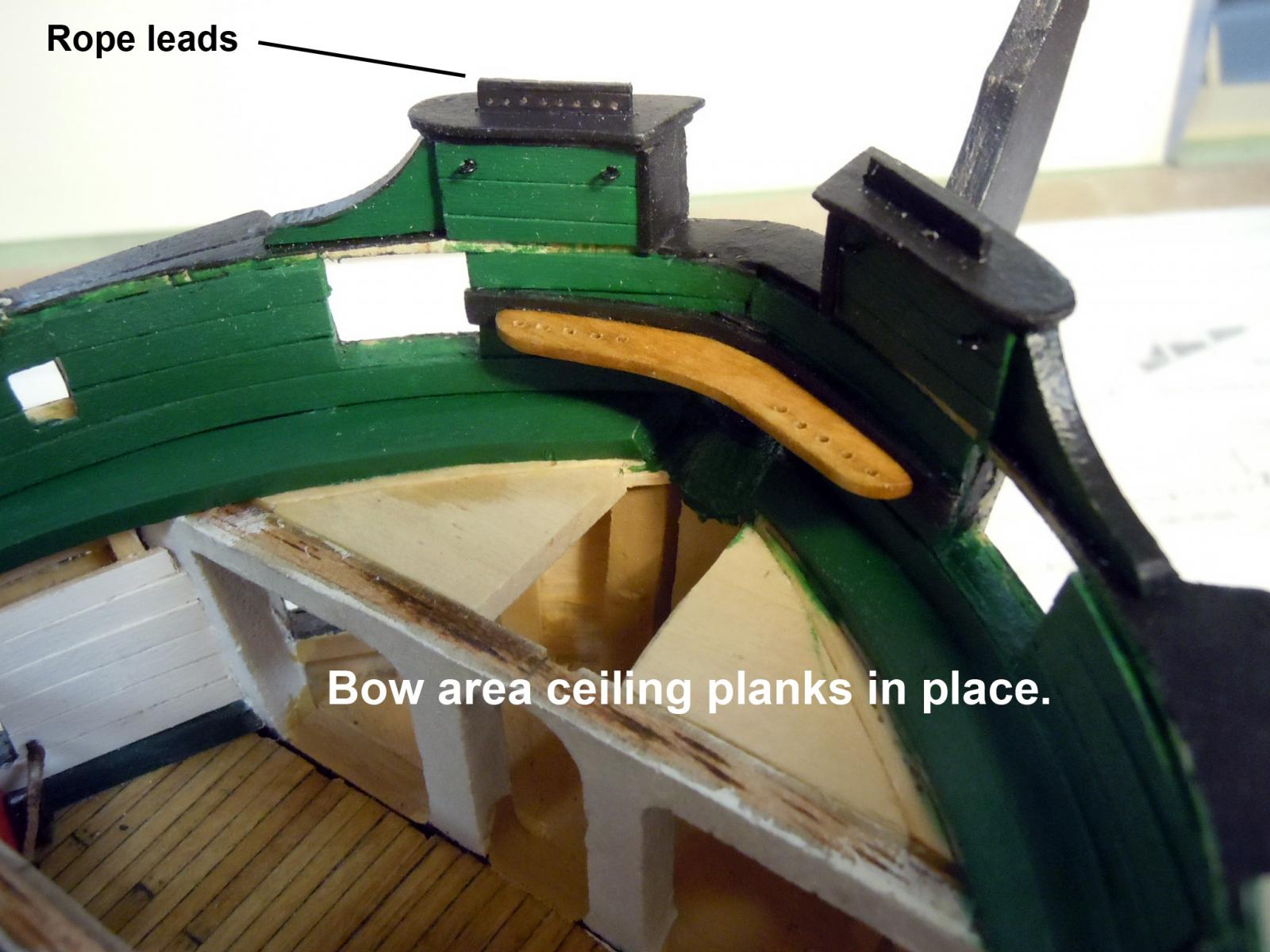
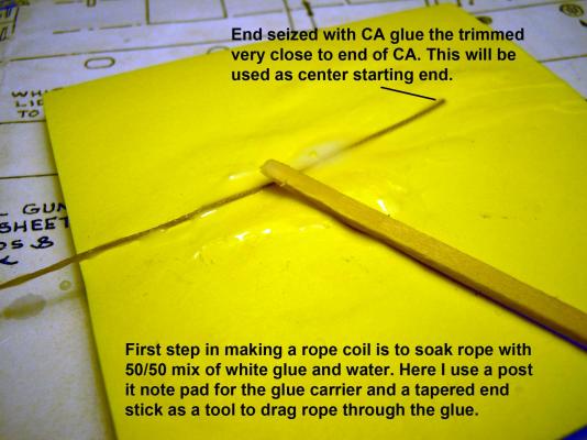
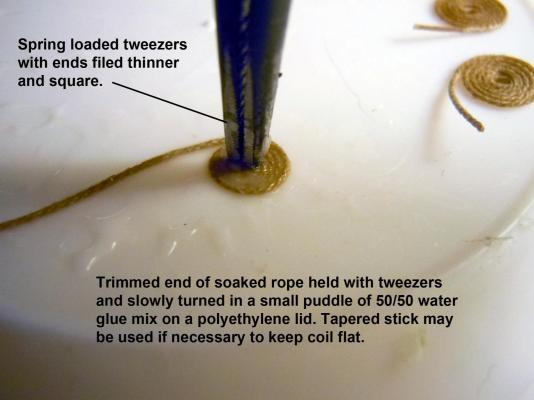
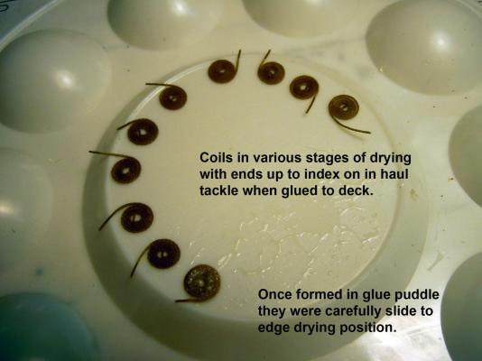
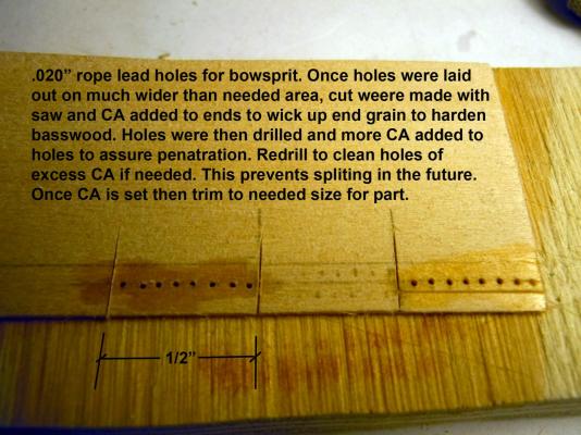
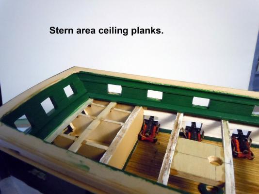
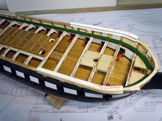
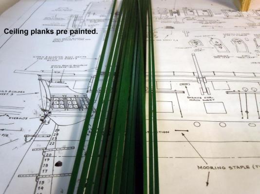
I moved on while waiting for the planksheer and ceiling planking to set and dry. Here is a sequence of how I make the rope coils that will lay on the deck by the in haul tackle. I am using my .013" rope that I made. The key is to file the end of a set of spring loaded tweezers for the twisting operation in a puddle of 50/50 glue/water mixture. The free end is positioned on the lid edge to dry in an up position for indexing into the tackle. Next I made the bowsprit rope leads which required drilling 8 .020" holes across a 1/2" wide strip. The challenge this small is splitting the wood hole to hole; so I harden the strip with CA allowing the CA to wick up the end grain and once set then drill. The holes are drawn on a strip over sized and will then be cut down to needed size. This works for many hole drilling operations with a series of adjacent holes. I then added the ceiling planks down both sides starting at the planksheer and working up cutting planks to size around gunports and other openings. Here is a bow view showing the planks as well as the rope leads, bow pin rail. I am finding that pre painting parts and then adding them keeps the finish clean and crisp. I pondered about adding the bolt heads and looking around at other builds I thought that they came off too large in scale. Here is a link to what I would use if funds were not an issue being retired. I have used these on car and plane builds on commissions I have done and Bob is great to work with and has a great selection of hardware: http://www.scalehardware.com/miniature-rivets-c-10 My son-in-law is back; he is a Captain of a Maresk container ship and is on a 72 day rotation and I will be helping him with a major house renovation/expansion doing things that we can do instead of the contractor, yesterday we removed stucco from the garage wall that will be bumped out and installed an attic drop down access ladder. The fun begins so ship building may slow down a bit.


-
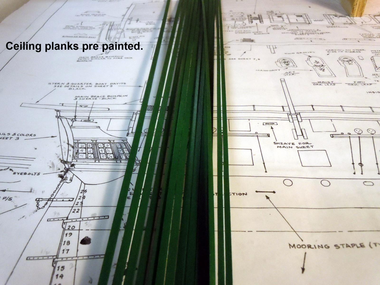
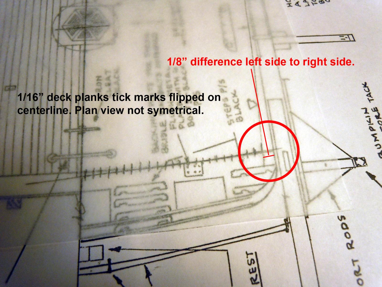
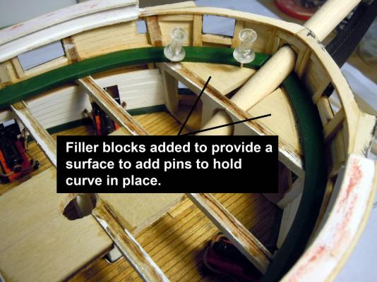
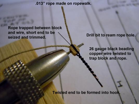
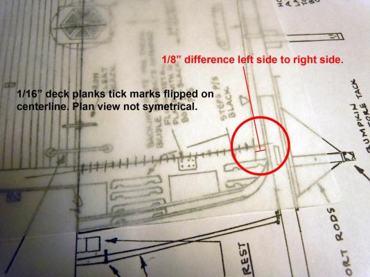
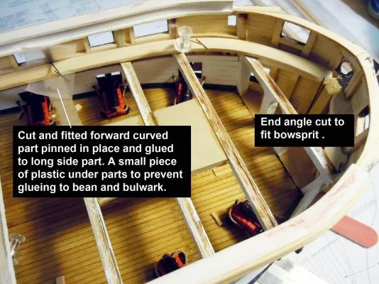
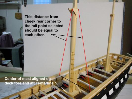
I finished up the planksheer and one tip I would suggest for others is to add filler blocks for pinning surfaces when working on forward curve. This shows them installed. I am also still working on the in haul tackle for the gun deck cannons going back and forth while waiting for paint to dry and making rope. Here are a couple of images of the tackle process using the rope made on the rope walk. I also sanded and painted the ceiling planks. Being new to painting with acyrillic paints I think I finally broke the code for a smooth finish as good as spray painting. First the planks were soaked with Wood Conditioner applied with a Q-tip and once dried completely sanded with 220 grit. Then painted with 91% isopropyl alcohol thinned kit supplied paint. No white primer! Top and sides of strips were painted allowed to completely dry and again sanded with 220 grit. Three coats of paint were applied to get the deep rich paint color. I will add the cut parts and paint the cut ends before gluing in place. NOTE: The alcohol evaporates quickly from the paint so more alcohol will need to be added. I check the viscosity before painting each coat. I was amazed how good the finish is on the planks. I am always thinking ahead especially while painting and in checking to pre-finish the spar deck planking I checked the stern by using tracing paper and discovered that the plans are not symmetrical left to right and have a 1/8" difference at the stern. Now what more surprises/fixes lie ahead since measurements were based off of centerline on the plan view. Moving forward I will center on the centerline of the masts and forget the plans. Now back to finish installing the gun tackle and then move on to the ceiling planks.
-
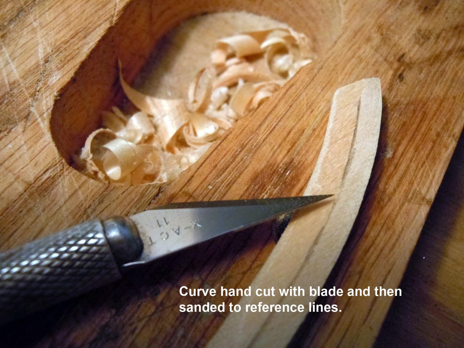
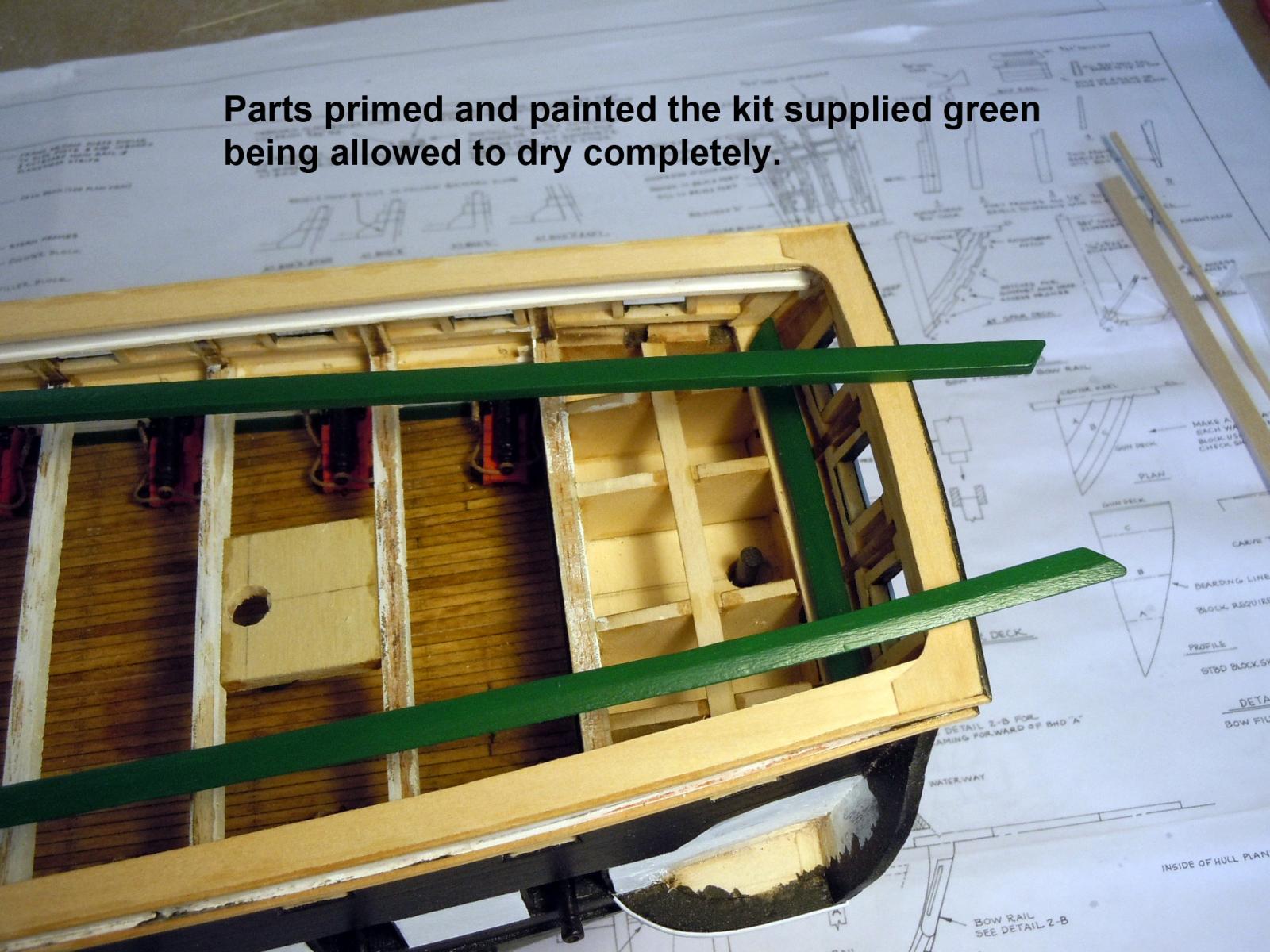
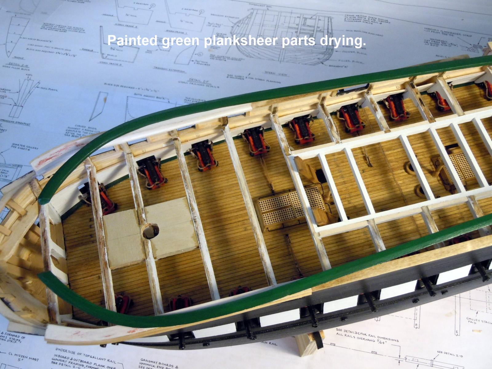
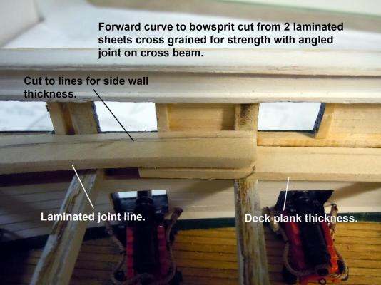
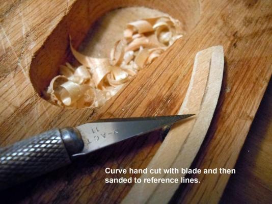
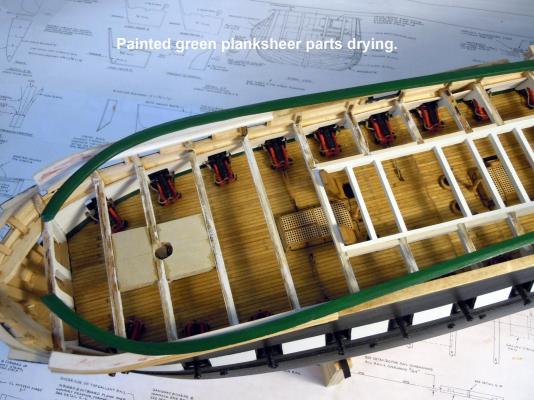
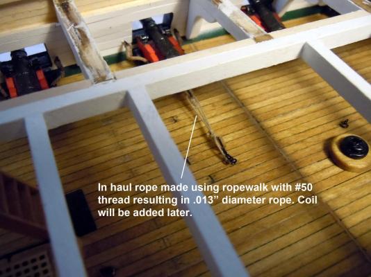
Thank you all again for your kind words of encouragement! While waiting for the thread order I decided to move onto the planksheers. In looking at the plans and the pictures I realized a difference with the "waterway" part that does not appear on the restored ship. I also checked dimensions from the deck beams to the gunports and no room for 3/32" waterway assuming 5 planks on the side wall. There will be no waterway. Here is the sequence of making the planksheer parts. I made them as separate parts rather than in place for ease of working on and the forward curved parts were cut from two sheets of stock glued together cross grained to each other for strength when carving. Once final fitted they were first treated with wood conditioner, sanded and primed. Then painted with the kit green paint thinned with 91% alcohol. However, due to the white primer four coats of green were required to get the rich deep green. In the middle of the above the thread order showed up and between painting parts and waiting for them to dry I set up the ropewalk and had some fun making rope for the in-haul tackle for the gundeck cannons. Chuck, the rope hardening worked, thanks again for the tip! I used the #50 which resulted in .013" diameter rope I needed. Now I will have to make enough for rope coils before adding the spar decking. Now to make more rope and rig the rest of the cannons.

-
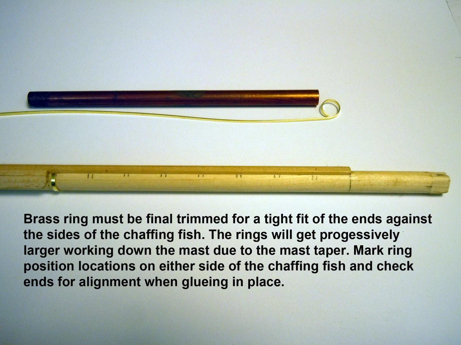
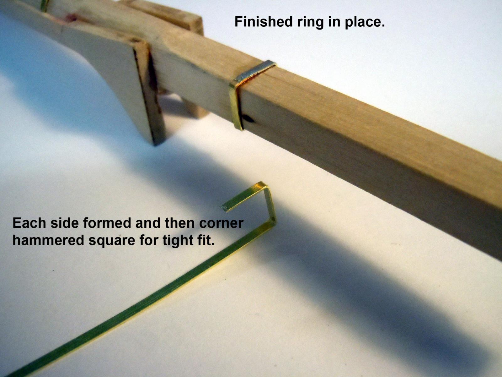
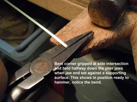
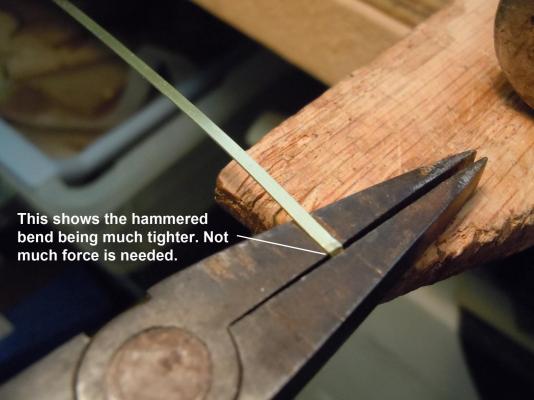
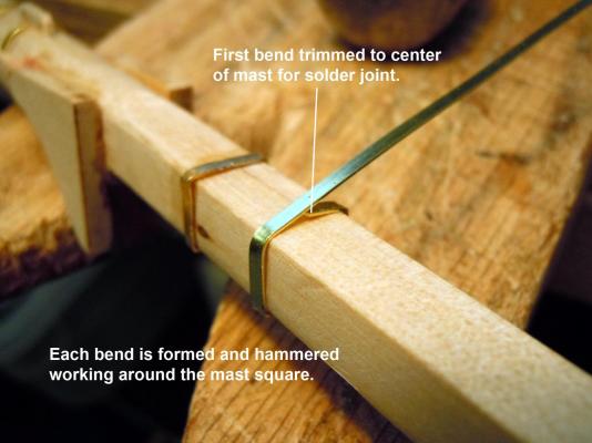
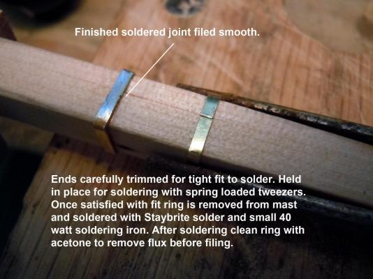
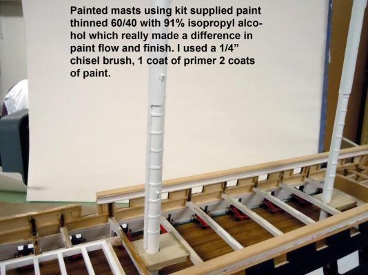
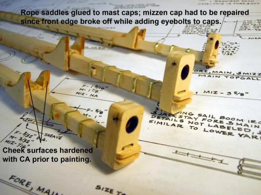
The mast rings were a slow tedious process but well worth the effort. The round and half round rings were much easier than the square ones. The round ones were glued in place but the squares needed soldering at the ends to complete them. The challenge really was that each one had to be sized and fitted in each position due to the taper of the masts. One thing I did in painting was to thin the primer and paint with 91% alcohol which made the flow much better and retained crisp detail including the joint lines in the chaffing fish. However, next time I may try using the wood conditioner first before priming to reduce the raising of the wood grain. Next I made the rope saddles that are located on the mast caps and added the eyebolts to the caps. The thread order should be delivered sometime today via UPS, in the meantime I will sort out what to do next now that the masts are set.


-
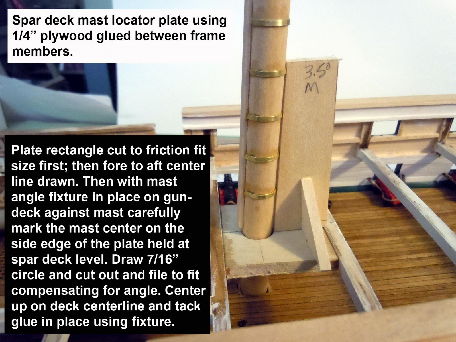
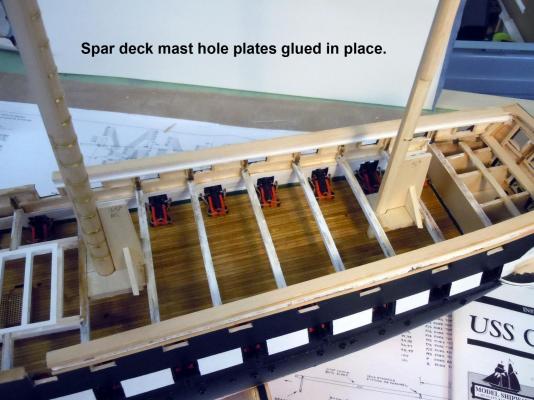
Jonathan, my pleasure; knowledge not shared is a waste in my opinion. Mark and J thanks for your encouragement! Kurt again thanks for the opportunity at the NRG Conference in October and yes I will gladly sign any of my books that are brought to or purchased at the conference. Thanks for the book plug! For the benefit of others the book is a primer on working with brass as a substitute material in model building. Many of the example techniques are not directly focused at ship building, but the basic concepts can easily be transferred as needed. Here are updates on the spar deck mast hole plates. The adding of the brass mast rings is a slow process since the masts are tapered each ring must be individually cut and fitted. Back to adding rings. Thanks again for all your kind words and ongoing encouragement.


-
Mark, Thanks for the compliment! I posted on page12 posted a link to military stars for medals a couple may work; but I have been busy with other things. I can always add the stars down the road if I cannot find another option. Sometimes I wonder if I am doing too many of the tutorials; but being new to ship building with no"sacred cows" my stumbling's may benefit others like myself learning the ropes.
-
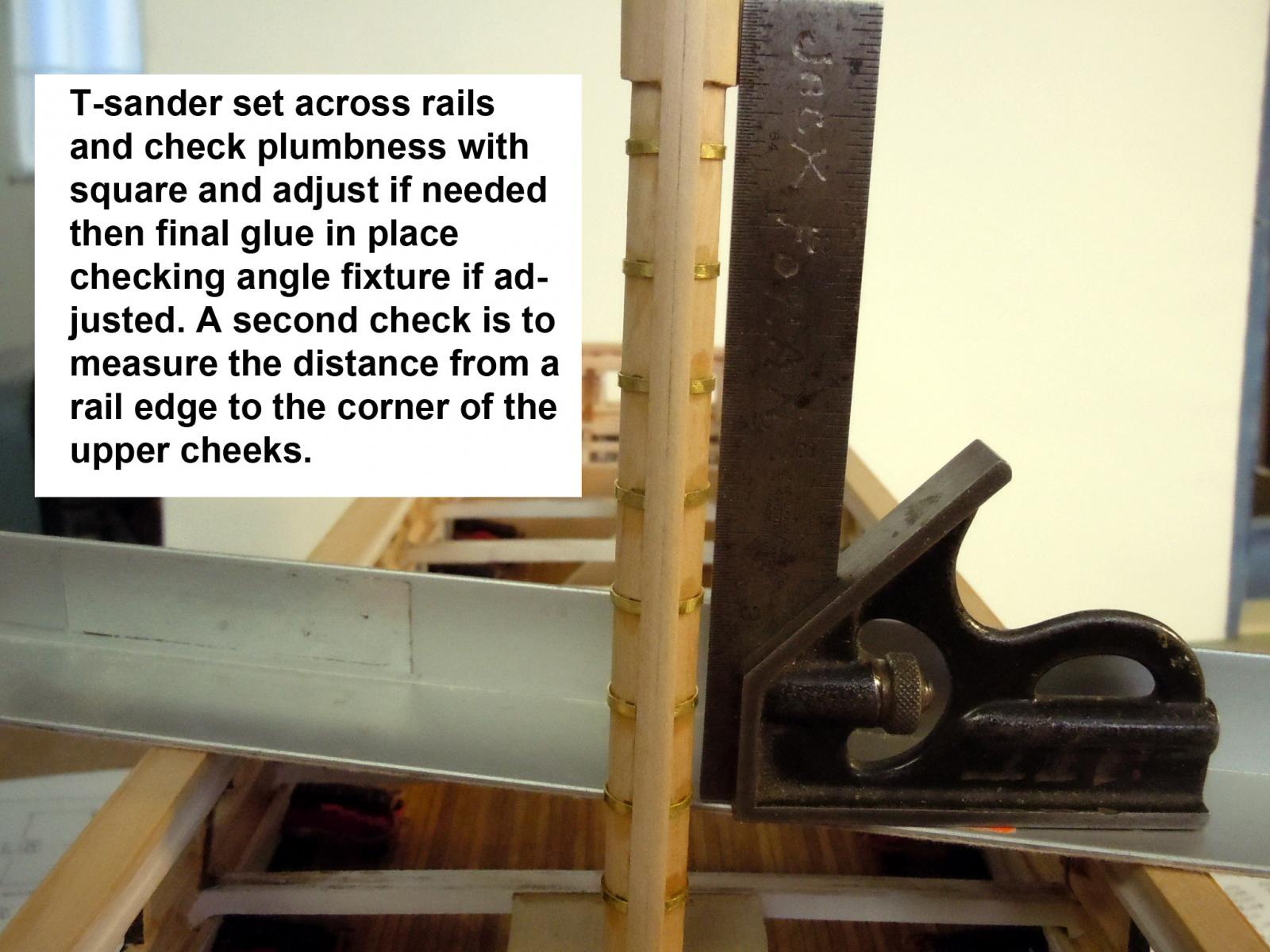
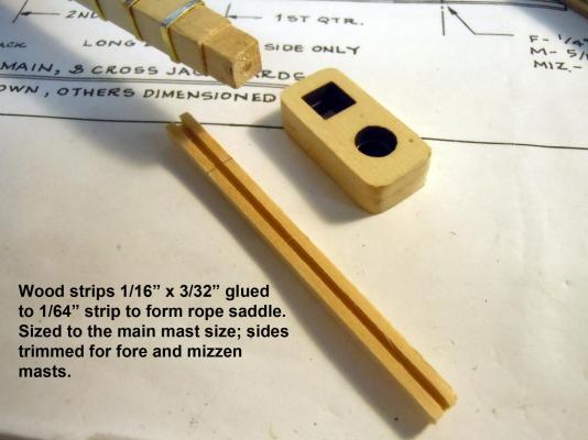
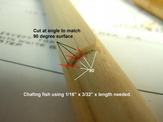
Jonathan, let's see if I can explain this with understanding. I used 1/16" x 3/32" basswood strips starting with the two center long strips cut to length. One was glued down the centerline of the mast. The second, the mating edge was first marked on the upper edge with the side of a pencil for a reference mark to cut and sand to; then carefully with an Xacto knife the edge was cut at an angle to match the edge of the strip glued in place on the center line. Once cut I carefully sanded the edge using a T-sander with 150 grit paper to match the pencil line. Carpenter glue was then generously applied to the edge in place and the cut edge added to it squeezing out the excess glue and cleaning it off and working it in place until tacked off. This process was then used on the shorter strips being alternately added to each side. This results in 90 degree to mast outboard surfaces. I clean the inside corner edges of glue with a wet q-tip for a clean joint. Remove as much excess surface glue as you can using wet towels or q-tips. The assembly was allowed to set overnight and then sanded at diagonals to the length of the mast to develop a smooth curved surface with tight joints. The instructions indicated to glue strips side by side that would have resulted in V gaps between the corner edges that would have to be filled with filler. Here is a picture with exaggerated red lines showing the angled surfaces being cut and sanded. Note the opposite is done on the other side. I hope this helps.
-
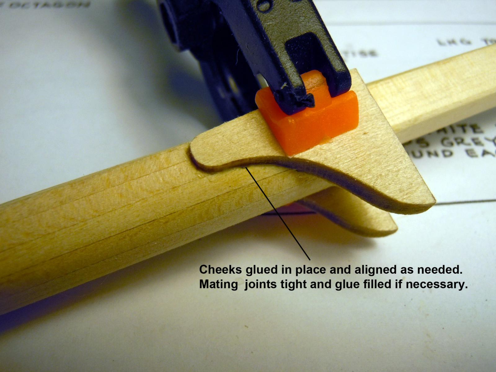
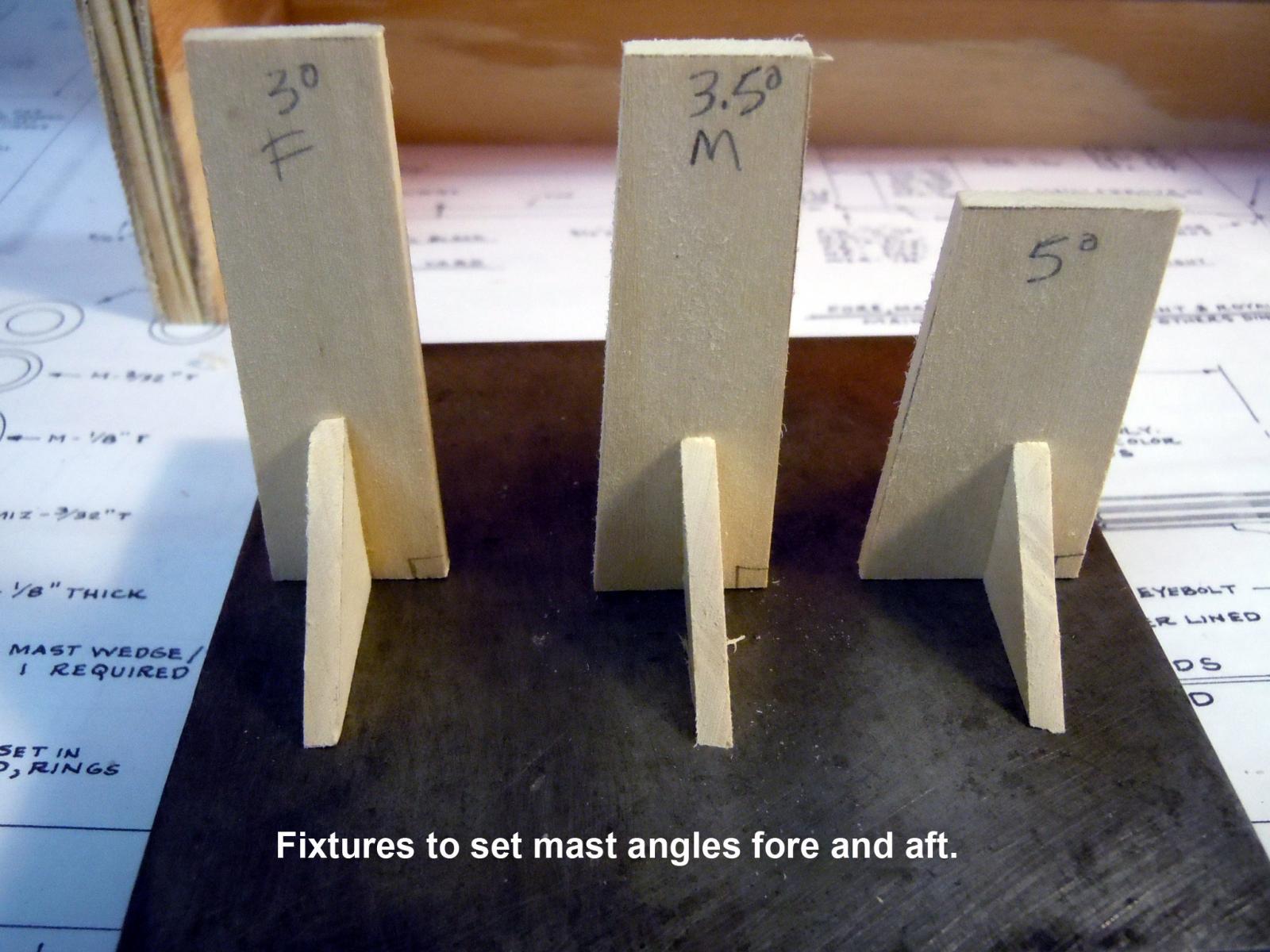
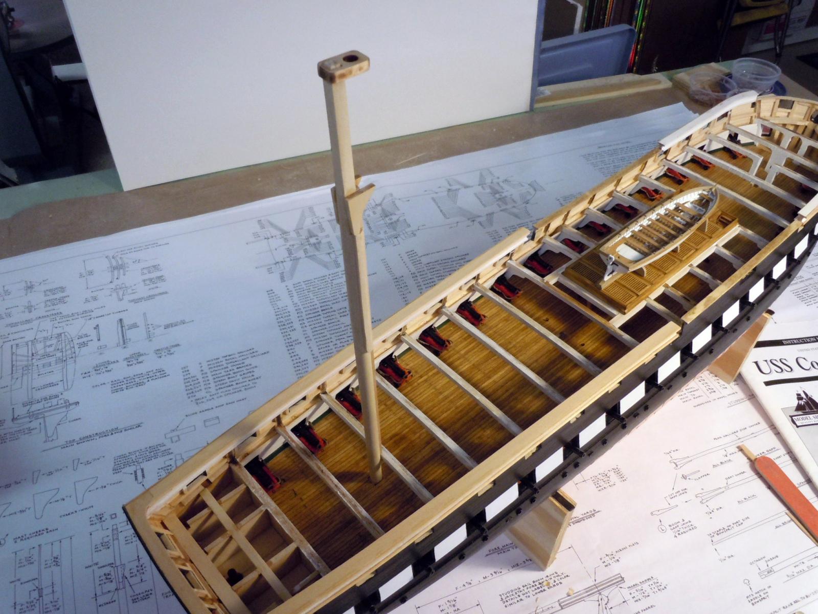
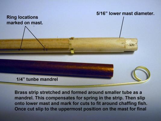
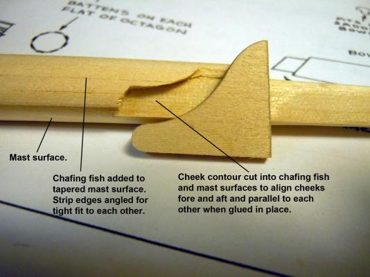
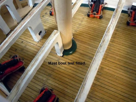
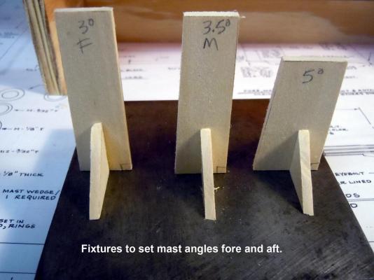
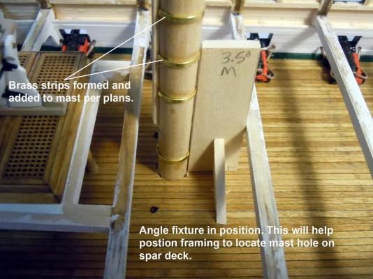
Finished up the mast boots for the gundeck. Then cut the three masts to length, tapered and shaped them per plans. Once masts were tapered and tops cut square I added the chafing fish to each. The strip edges were angled for a tight fit to each other rather than the plans suggestion of just adding filler which could have lead to flat spots once the filler was sanded. Experience from previous model builds. Once the chafing fish were sanded I then cut in the locations for all the cheeks. To cut the shapes I used plunge cuts with the tip of a #11 blade to form contours. I then stretched the brass strip from the kit to straighten and form the mast rings for the main mast as a test. I then made angle fixtures for each mast at their required degrees. These will be used to build the framing around the mast to locate the mast holes on the spar deck. I also realized that I will have to remove the bottom brass ring to achieve a tight fit through the mast location holes and spar deck boot holes. Now to finish up the brass rings on the fore and mizzen masts and develop the framing for the mast hole locations on the spar deck.

-
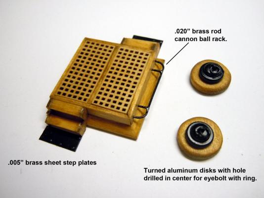
Actually the steps are the same and just a different view. I used the same photo for reference. The round things were a piece of round wood stock with the edges slightly rounded then the two black discs were cut on my lathe using aluminum bar with the smaller disc turned with a hole to receive the eye bolt and before cutting it off the top crown was added using a small file. The two discs were glued together then both glued to the wood after being painted. I hope this helps.
-
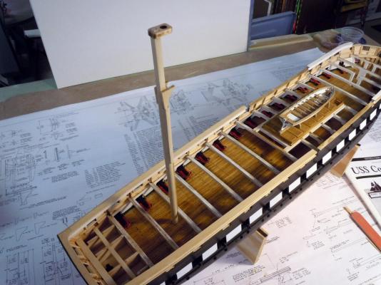
Steve, David thanks! I finished up the second hatch with the cannon ball racks with steps and the round anchor points with eyebolts. Not sure what they are called but I suspect that they are used to rope in cargo when being loaded. Clarification is welcomed. Next I moved onto to fitting the masts in order to add their boots on the gundeck. In addition to just fitting I am also building the lower mast elements as well. My thread order was confirmed with a UPS delivery of April 7 when they arrive I will be able to rig the cannons in haul lines. Parts in place. Here is the lower mizzen mast pressed in place. I will move forward on the main and foremast which will keep me busy for awhile. The boots are the last main parts needed to finish up the gun deck on this build.
-
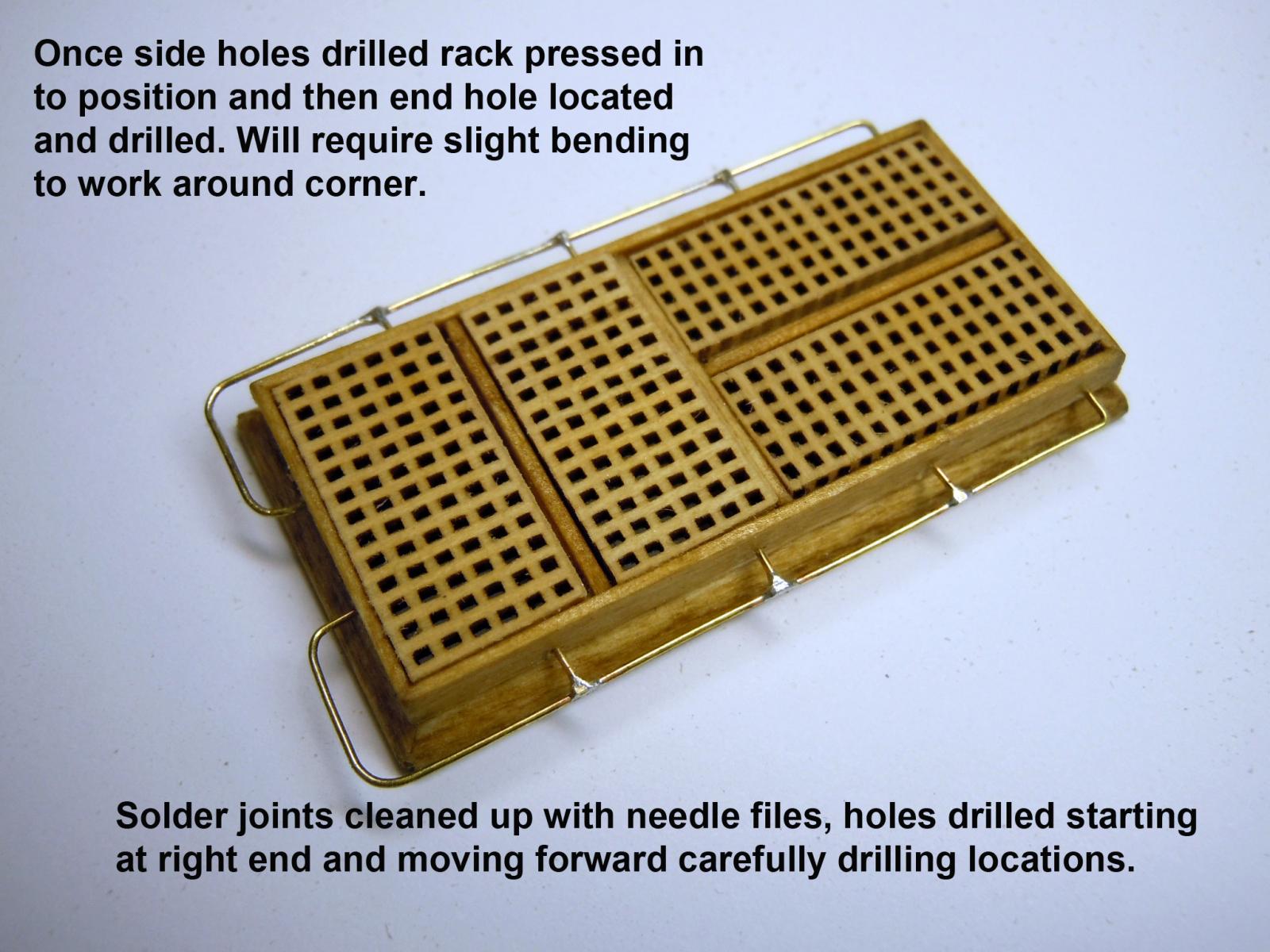
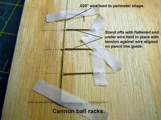
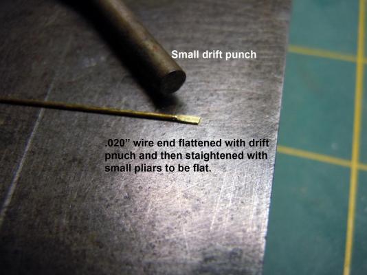
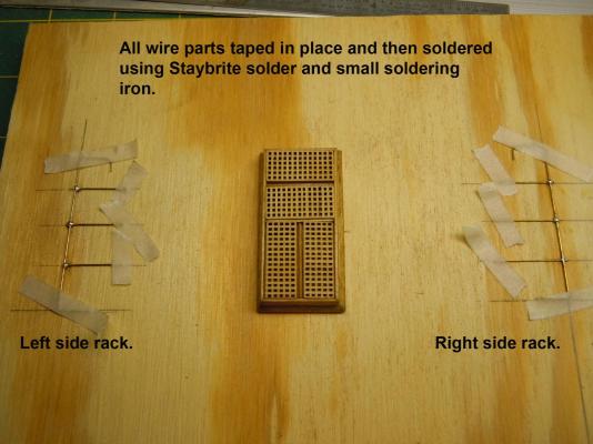
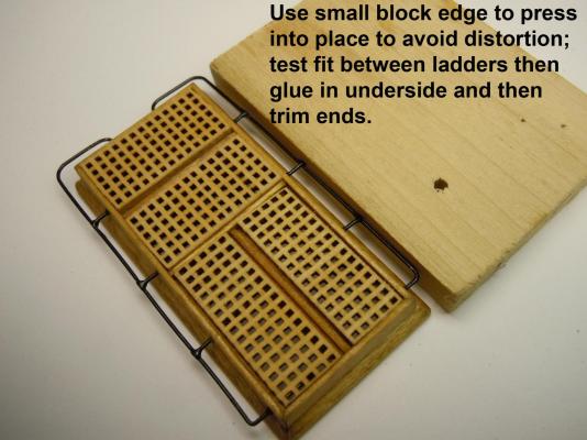
Chuck, thanks for your insights; I guess I may have gotten lucky since I stained and let the rope dry in place before cutting I may have relaxed the rope enough to not unravel. I am waiting for my rope order so I will follow these tips when I start making rope. In the meantime I have moved back to the gundeck and added the cannon ball racks to the ladder ways which I will leave the grates in place for this build. There will be plenty of racks to build so I thought this may help others with their builds. I used .020" brass wire and formed two identical perimeter shapes. Next I used a small punch and flattened the end on a steel block; this provides a flat surface to carry the solder on a round wire for a strong joint. I drew patterns on a small piece of plywood using a square and taped all the parts in place on the pattern. Once soldered, the racks were cleaned with acetone to remove any residual flux the ends were trimmed and cleaned. Here is a sequence of photos. Now back to gun deck items.

-
Chuck, Thanks for the feedback and pictures. I plan on sorting out the hand cranks as well and like your idea of the machine screw. I also need to learn more as well and that will come with practice. You mentioned "DONT FORGET TO HARDEN the rope after you make it. Thats the most important part." What do I have to do to Harden the rope?
-
Rope Making Basics
xken replied to mikiek's topic in Rope Making/Ropewalks's Discussions about Rope Making
Mike, here is a link to one stop shopping for threads to make ropes. This one has all the sizes however, the only colors for all are White or Ecru and will require dyeing black or brown. I have ordered Sizes 10, 20 and 30 in black and mocha brown of the DMC Corbonnet type inbound to me by UPS. Check out my USS Constitution for examples of test rope I have just made. http://www.hhtatting.com/results-threads.cfm?SubCategory=27 I had no problem making rope first try. Here is another link at the same site to get Lizbeth 40 and 80 sizes in colors Black and several Browns. http://www.hhtatting.com/CategoryResults.cfm?Category=5 -
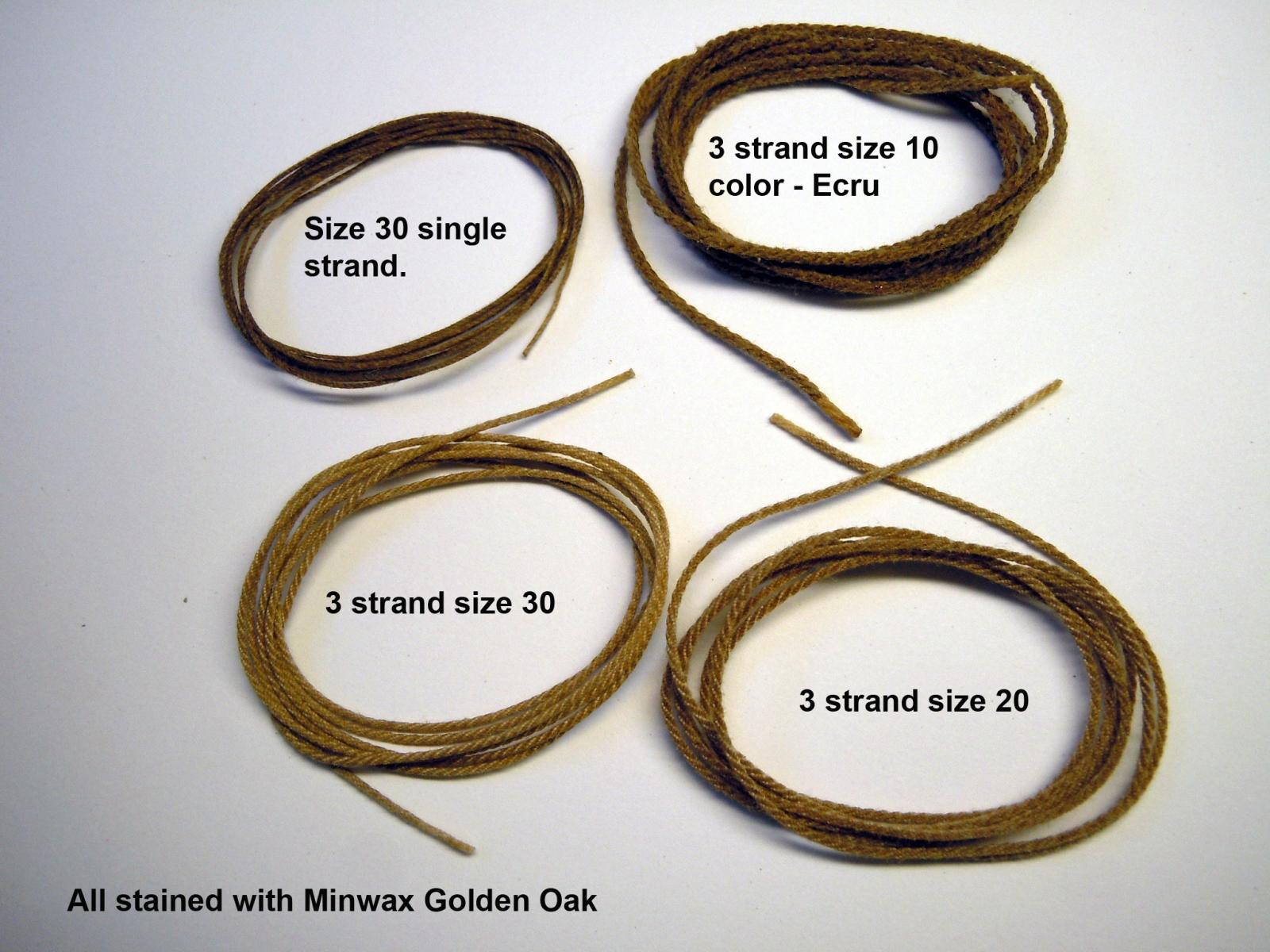
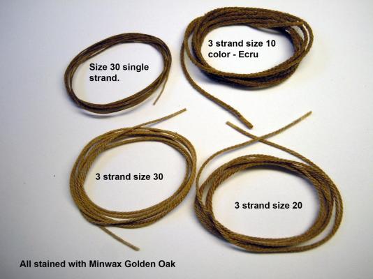
Jon, thanks again for your explanations. Right now I have made ropes using each size that I have in hand and will now wait until the black and brown thread order arrives before making more rope for the gundeck cannons. I have a few additional thoughts on improvements but will work on them down the road when I get more serious about ropes. I will also be looking around for source of smaller sizes of thread as well. I appears that they come in increments of 10 up to 100 being the smallest. Here are the test ropes of each size. the single Size 30 is .015"; then .024"; .030" and the largest .038". These were measured using the ends that were CA'ed. The largest was color Ecru and then stained which is why darker. The smaller were white and then stained and are a great match for weathered rope as seen in some of the real ship photos. This week is spring break for pre school so we have grandparent duty for the mornings with our 2 and 4 year old granddaughters. This morning it is off to the zoo.
-
Jon, Thanks for the suggestion I just may do that myself once I get a few experiments done. I just ordered some Black (10,20, 30 sizes) and Brown (20, 30 sizes) threads from the link above. I have to think of how to setup a work station to make longer rope when taking a break from building. I am amazed how well this rope walk is doing as is and of course the engineer in me has already thought of upgrading to nylon bushes along with the screw heads.
-
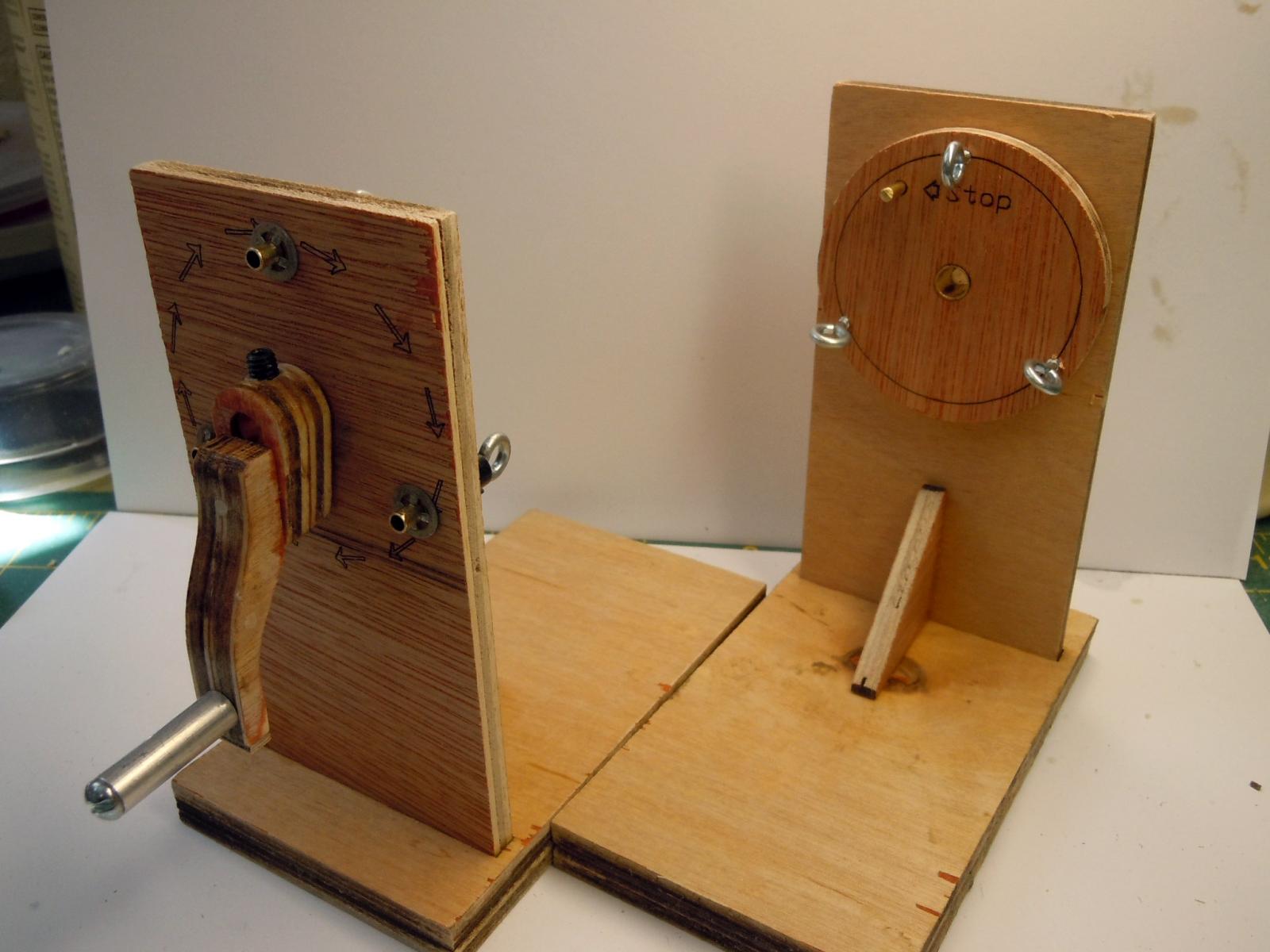
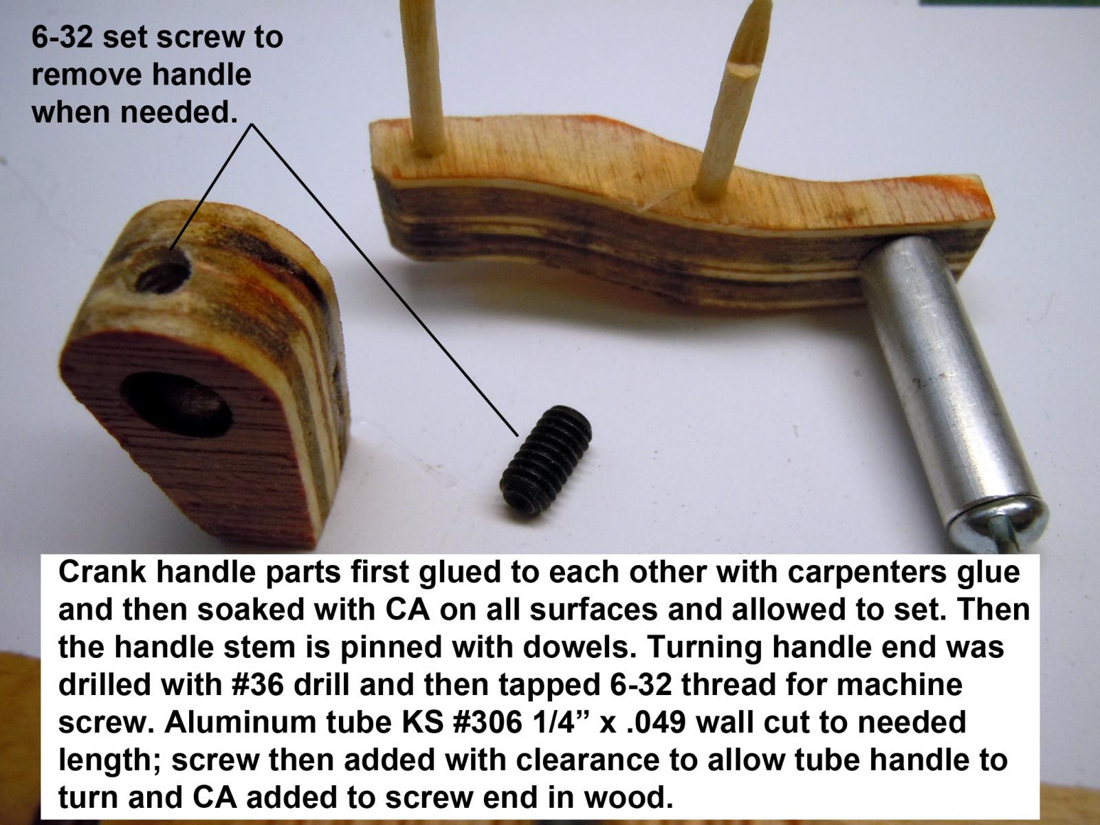
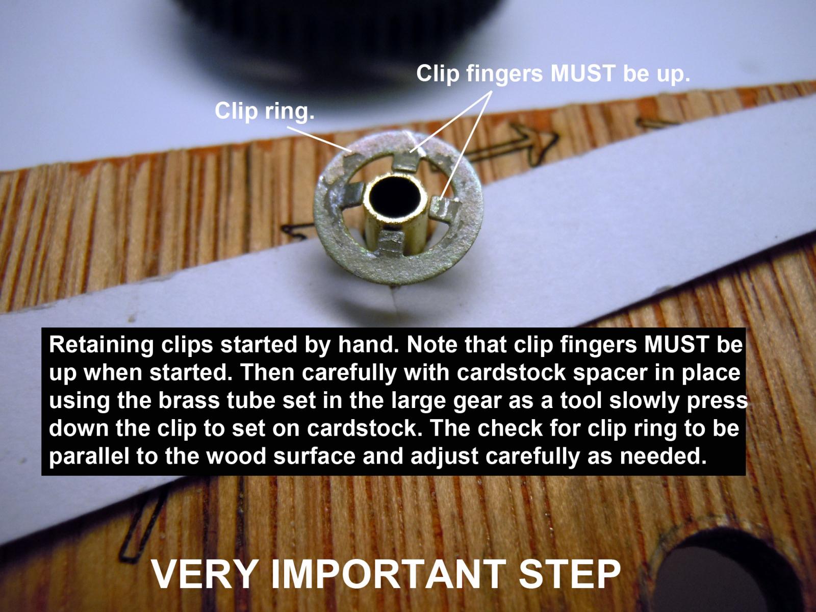
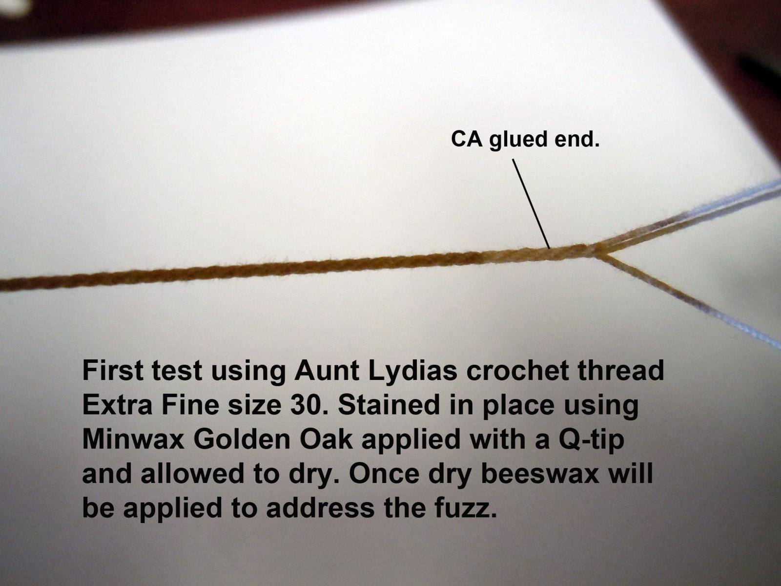
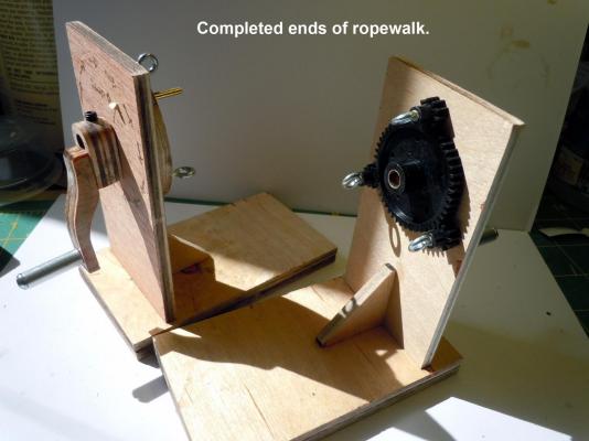
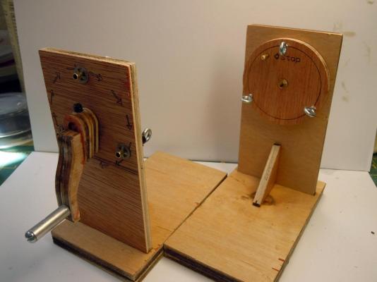
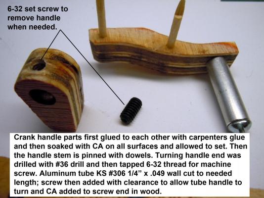
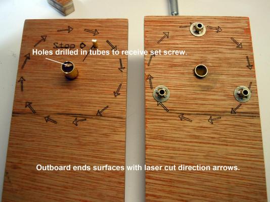
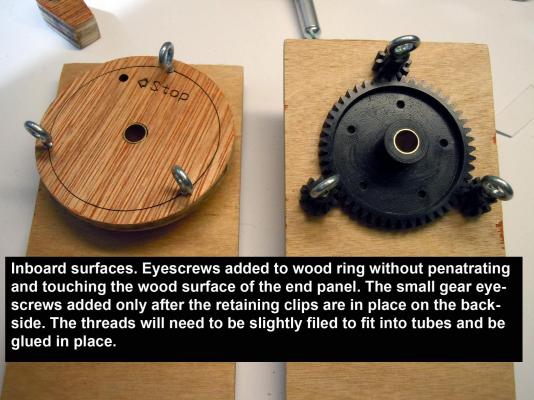
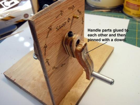
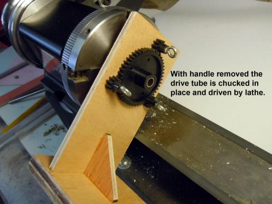
Now lets build a rope walk; as well as improve and enhance what came. Once I opened the kit box I immediately recognized an issue with the plywood the parts were cut into. While not the cheapest grade of plywood it is close. The two sheets were slightly warped so the base units once cleaned and fitted were glued together with opposing curves to flatten, clamped and set aside to dry. Here is what they looked like finished up. The handle parts were glued together and then all edges soaked with CA to strengthen and harden. Once set were sanded and pinned with dowels to help avoid breaking in use. I also cut aluminum handles instead of the vinyl tube that was in the kit. This shows the backside. This is the most important step for a smooth operation. Get the clips spaced with card stock and parallel to the wood surface. I used the tube inserted in the large gear to push the clips in place against the card stock. This shows the eyelet sides or inboard. This shows the handle in place. I opted to pin with a dowel again for strength. I also am using set screws into the brass tube so the handles can be removed. to be setup in my Sherline lathe which I may experiment with once I am a little smarter. I set up and made my first rope about an arms length apart per instructions. I used size 30 to start with I have sizes 10, 20, and 30. The higher the number the smaller the thread. The hand cranks were not the smoothest but worked fine and my first attempt I consider a great success in that in holding Chuck's next to it, it looked the same other than the color. I glued the ends and then stained it in place and let dry. Beeswax took care of the fuzz. In searching around here is a sight I am going to order some brown colored size 30 from. Look around and they have smaller sizes but only in White and Ecru. http://www.dmc-usa.com/Products/Needlework-Threads/Crochet-Threads/Cebelia.aspx Back to more rope making experiments and learning the process to get better.


-
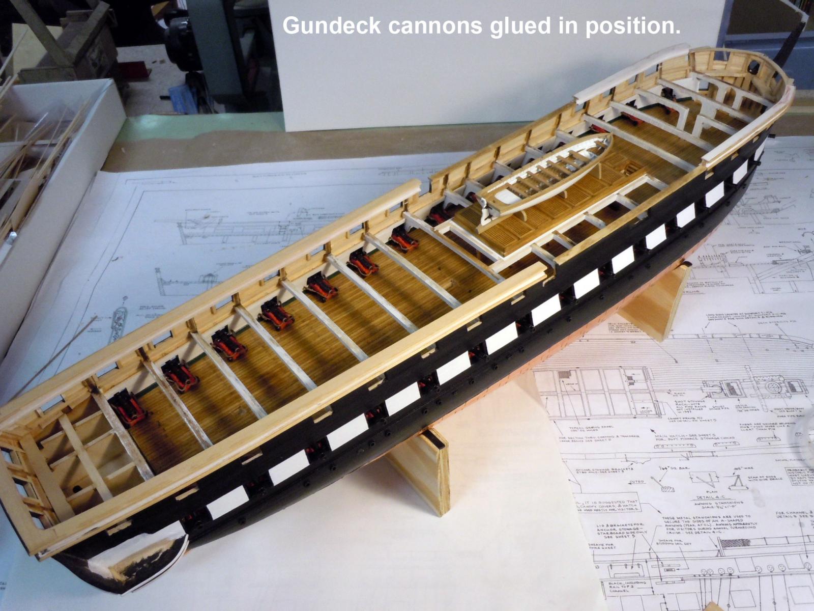
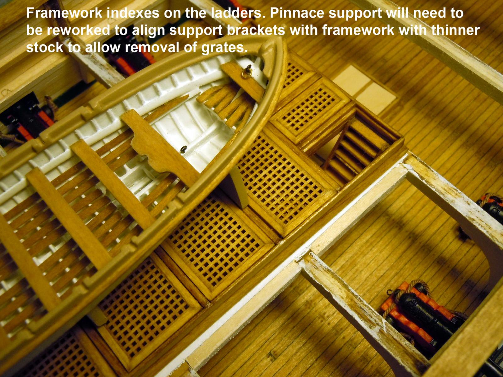
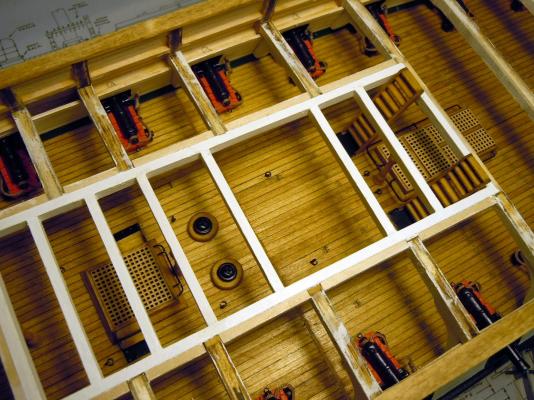
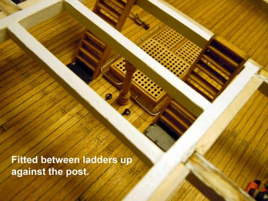
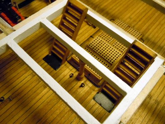
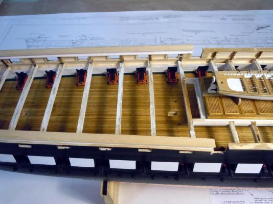
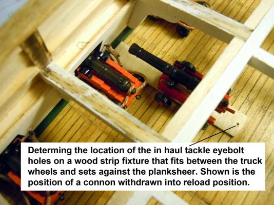
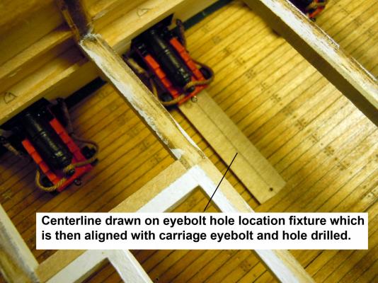
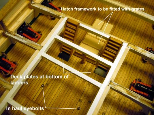
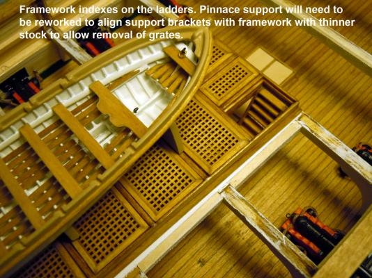
Had a great fun Easter weekend with the grand kids decorating eggs and then the egg hunt in the backyard yesterday. I was able to finish gluing in position all the gun deck cannons. Here they are in place. I then needed to locate the in haul eyebolts for the cargo hatch area. The photos of the restored ship do not show these; so I had to sort them out by using a cannon in the reload position and factor in the tackle blocks. I then made a strip to fit between the truck wheels and drilled a guide hole. I drew a centerline on the strip to align with the eyebolt in the gun carriage for positioning and drilling. I had to add the ladders in position to locate the last eyebolts adjacent to the wood support post that will lay in front of the ladders. I am sure these were positioned to avoid tripping and are shown in one of the photos of the ship. I also added the deck plates at the bottom of the ladders made of .005" brass sheet and added the bolt heads by using a center punch on the backside on a steel plate which provides a great looking head. I positioned the pinnace in place and quickly saw that the support will need to be rebuilt using thinner stock and the brackets will need to align with the framework structure to allow removal of the grates. Now back to gundeck work on cargo framework and grates.

-
David, thanks I suspected that is what you did. I am very proficient with CAD and Photoshop so making stars the correct size is not an issue. I would print them out on photo paper for crisp bright white. I am holding out for 3D stars; I have found some but 1/16" too large. I will keep looking and will use the printing process as a last resort. The only issue with polystyrene is that it will turn almond over time due to UV light exposure, so should be painted. Thanks again!
-
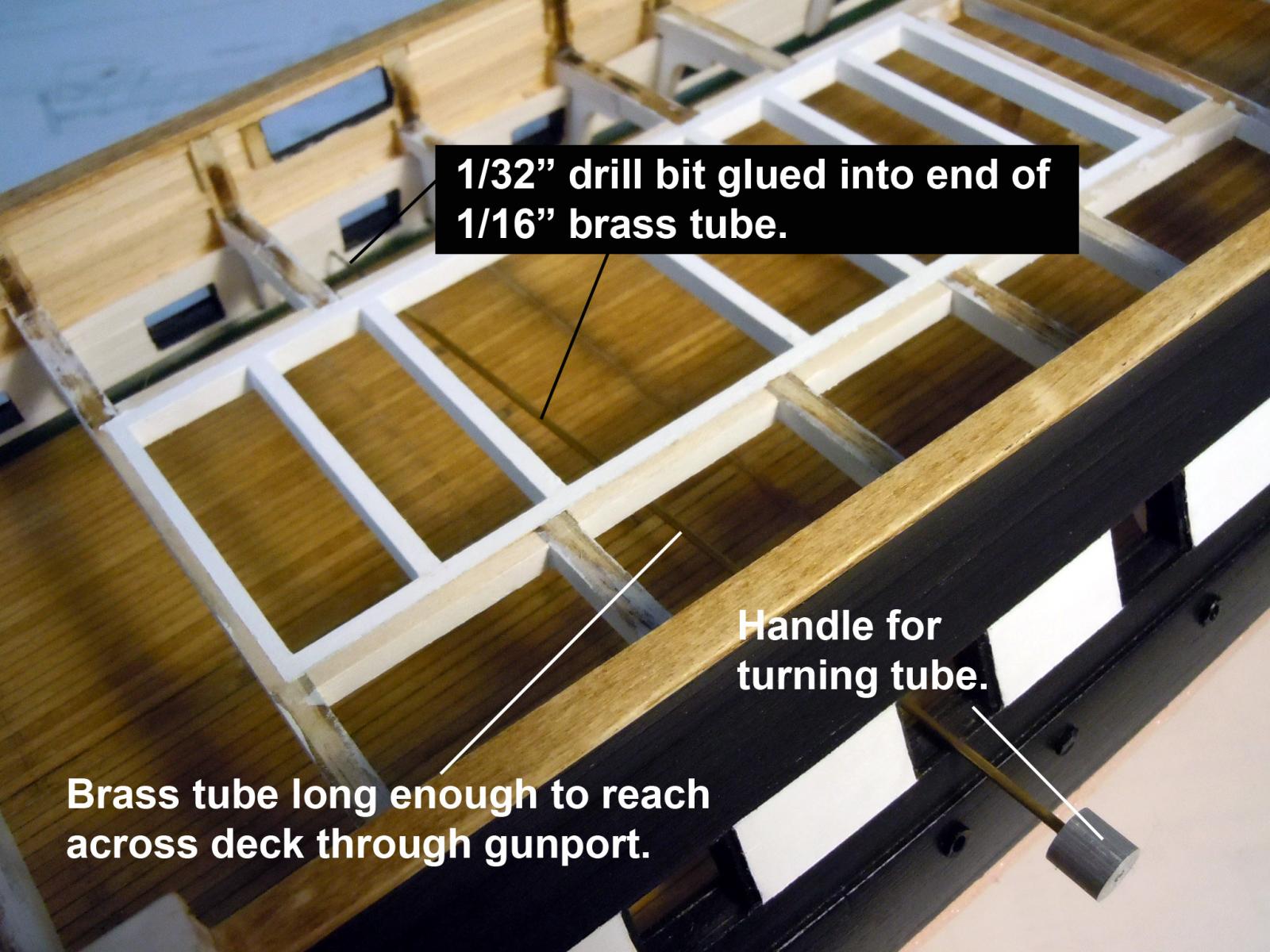
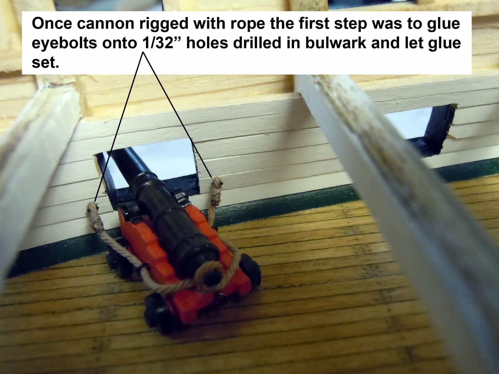
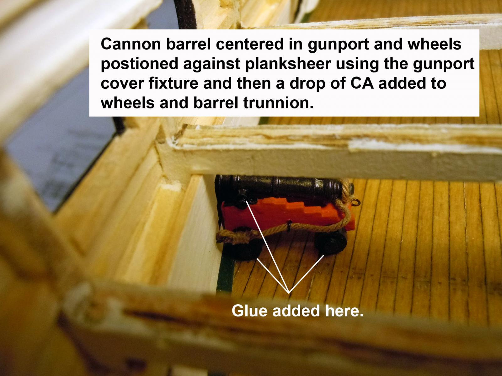
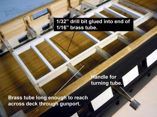
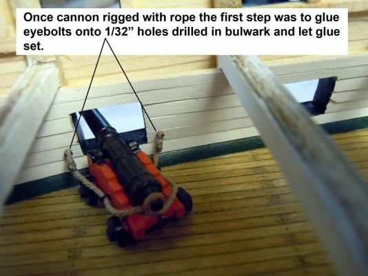
Thank you all for your kind words of encouragement! David I was looking at your build and was wondering what you used for the transom stars? The installation of the cannons has started; I will be doing them in batches to break up the boredom and give the eyes a break at the tedious tying off of the eyebolts. The first challenge was the drilling of the eyebolt holes with all the upper deck structure in the way. I again fell back on past experiences and made a long drill handle by gluing a 1/32" drill bit into a length of 1/16" tube long enough to reach across the deck going through the gunport. Once the holes drilled I first glued the eyebolts in place and let the glue set. The I positioned the barrel into the gunport covers to center the cannon in the gunport, positioned the front wheels against the planksheer and added a touch of CA to the wheels and trunnion to hold the cannon in place. This is why care must be used in gluing the trunnion straps in place and allow the barrel to move in the straps. I am using the planksheer for consistency of positioning. Now back to installing the cannons which will keep me busy for a few days.

-
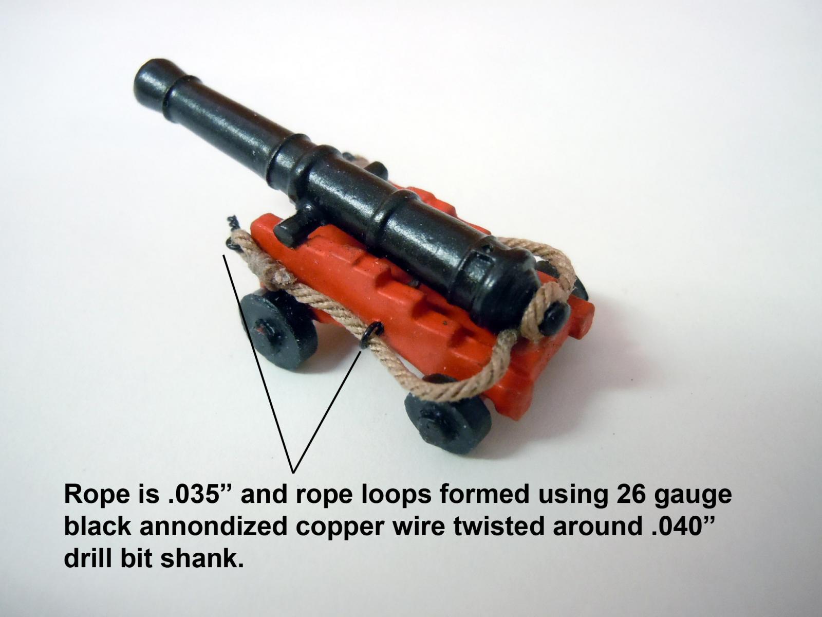
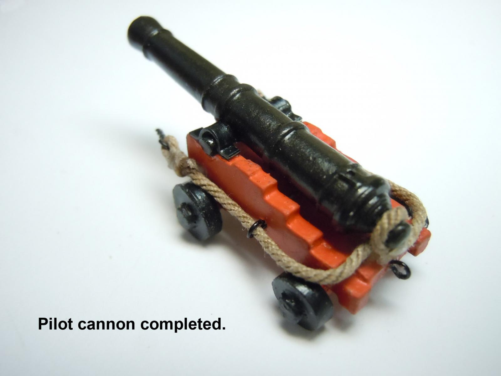
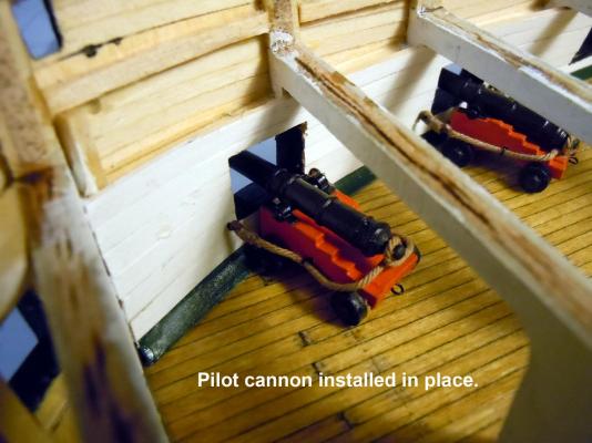
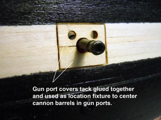
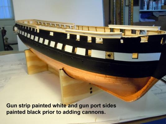
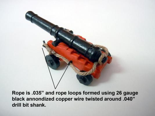
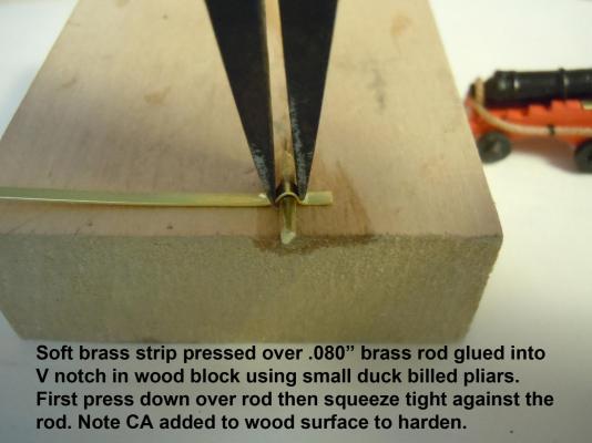
The cannon build continues with all parts now drilled and painted. I built out a pilot all the way to have a guide and bench mark to check against. The challenge I am finding is that there seems to be two different laser cut patterns in the gundeck kits with the carriage of one being slightly larger than the other that impacts the height position in the gunport. I used the brass strip in the kit for the trunnion straps and 26 wire for the rope rings. Keep in mind these will be on the gundeck and only the best ones will be positioned in the cargo grate area for viewing; the balance will only be seen if peeping through the gunports. I tacked together the gunport covers to be used as a location fixture when gluing the cannons in place. I realized before I got ahead of myself that I should paint the gun strip white and the gunport sidewalls black before installing the cannons. Here I have added the .035 rope from Chuck and tied the ends trapping the twisted wire loop that will attach to the bulwark by drilling .032" holes. Here I am using the soft brass strip to form the trunnion straps. The trick is to add the straps without gluing the barrel in place so that it can be adjusted to the gunport later on. Here is the pilot cannon completed with only 29 more to build. Now back to cannon building.

-
Tom, looking great! I can sympathize about the wheels I just cleaned up 120 for the gundeck on my build. As I add them to the carriage I sort through the pile and try to match two of the large and two of the small and then rotate the oval ones to the best fit for level.
- 1,348 replies
-
- 2
-

-
- constitution
- model shipways
- (and 1 more)