xken
-
Posts
841 -
Joined
-
Last visited
Content Type
Profiles
Forums
Gallery
Events
Everything posted by xken
-
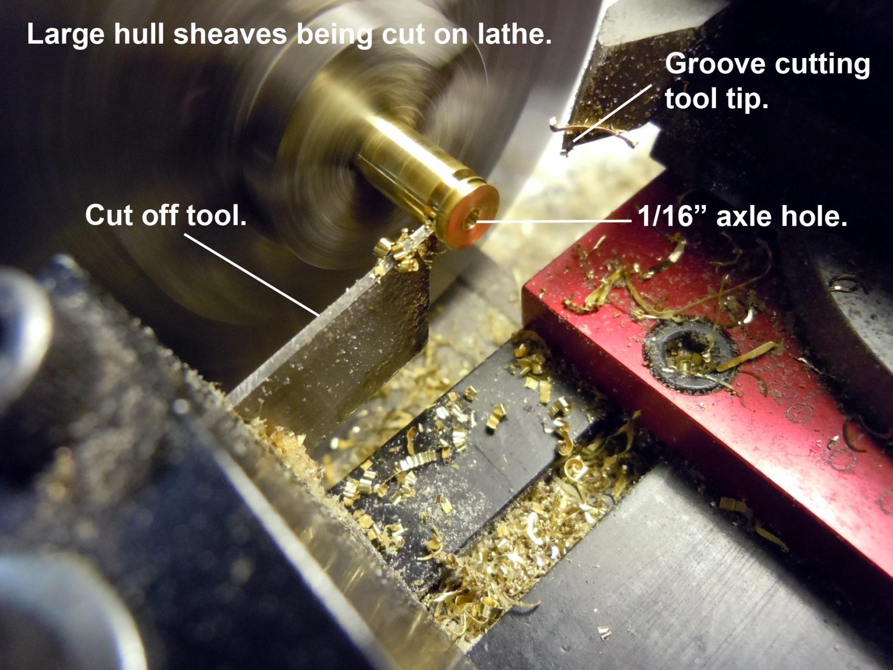
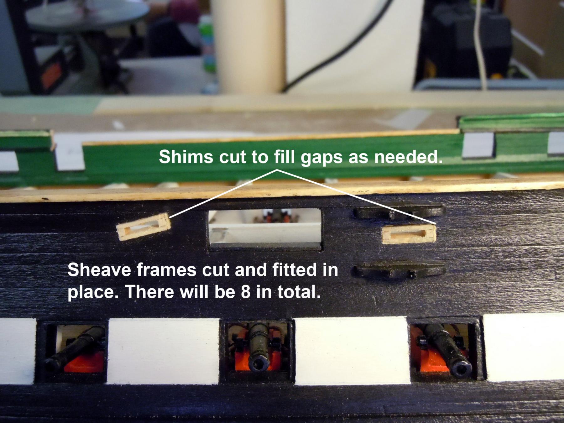
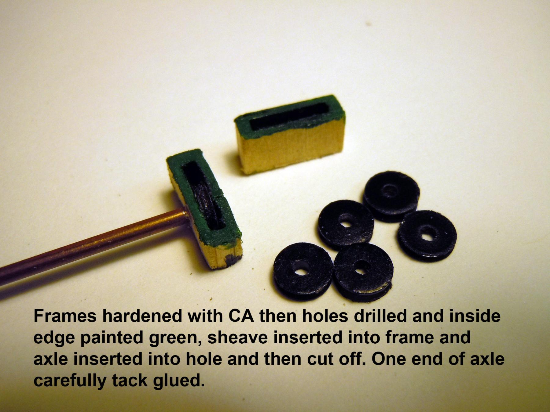
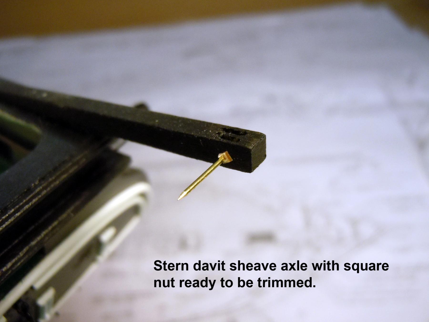
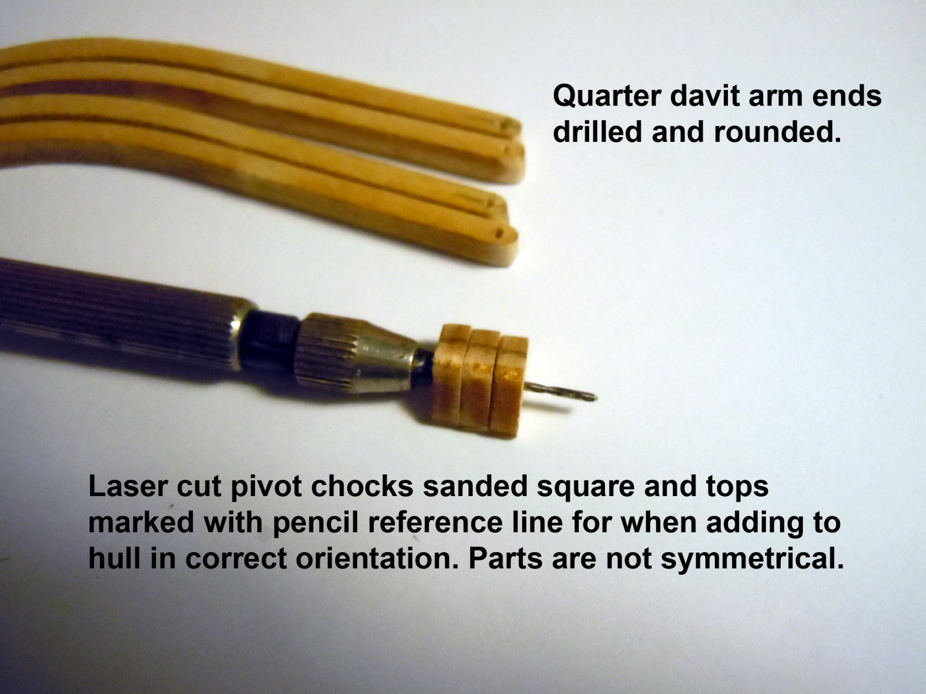
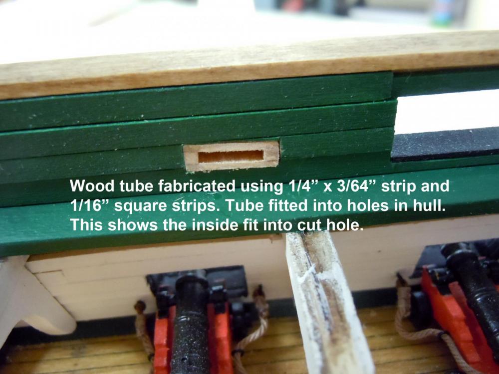
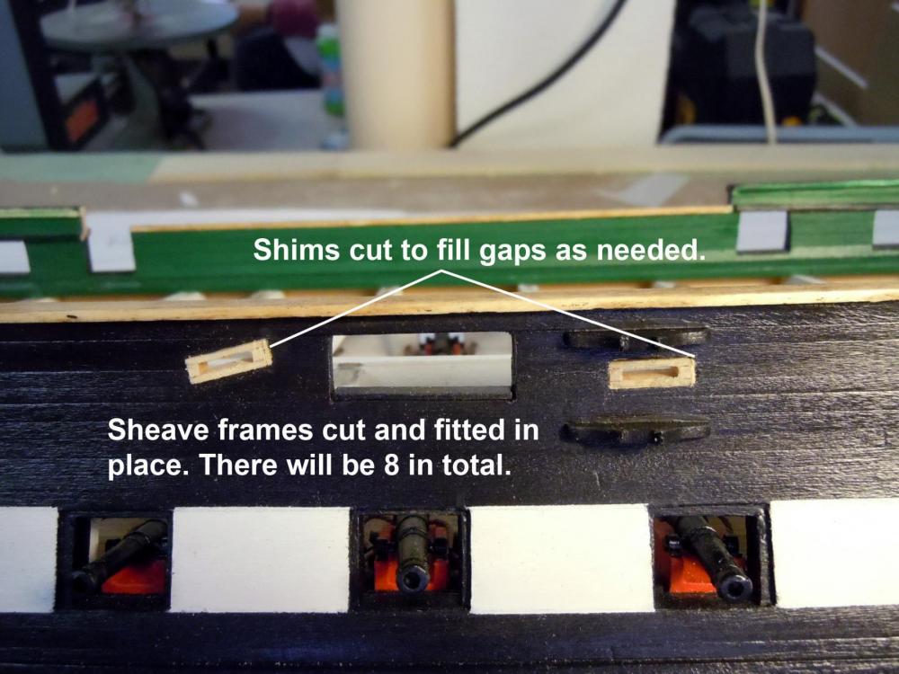
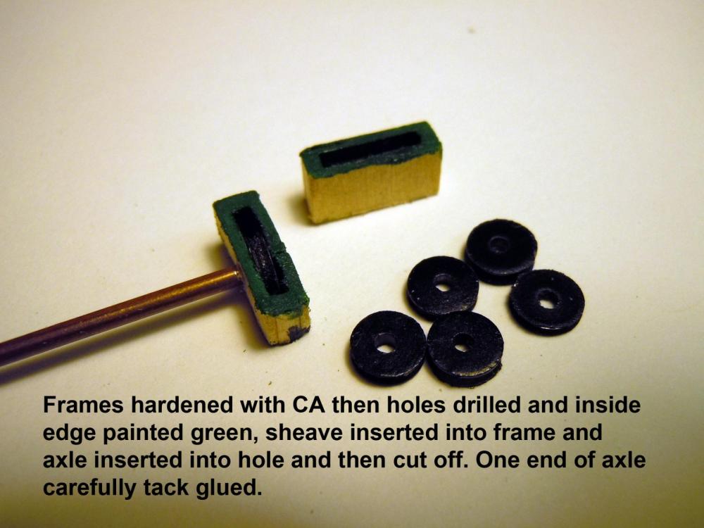
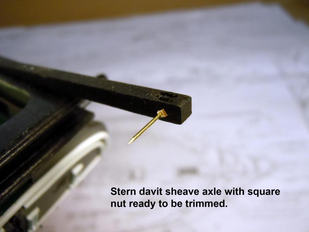
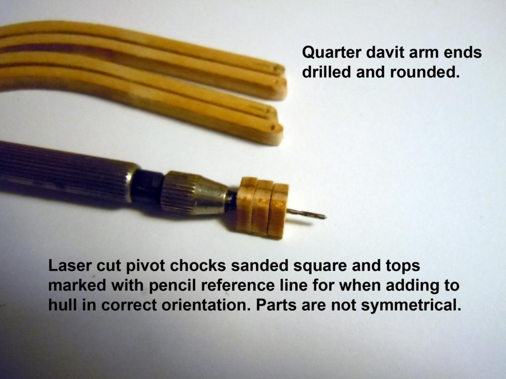
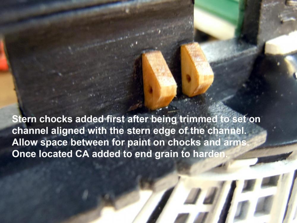
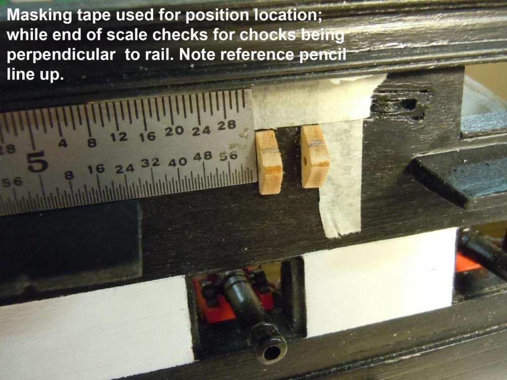
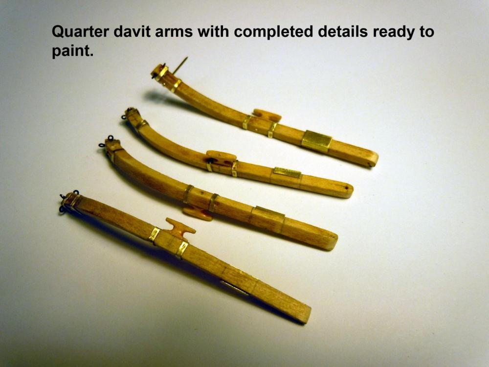
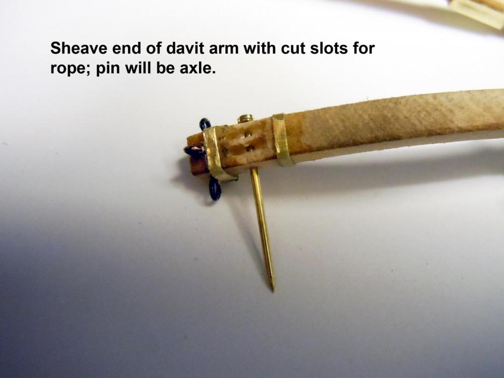
 I have been busy this week helping the kids with their house renovation and renewing my familiarity with joint compounding tools doing what I can with my back issues. Anyway I have done a few things with hull details; adding channels, davits and sheaves. I sheaves started with fabricating a wood tube to represent the sheave frame that extended through the hull walls. Next holes were surgically cut for as tight a fit as possible with any gaps being filled with shims. Once the frame parts were cut they were hardened with CA and then axle holes were drilled. Here are a few pictures showing the process. I also added the stern davits with sheave slots and drilled for axle. This shows the pin with a square nut cut from 1/64" wood stock. I also carved the cleats for each. For the cost of this kit one would think they would include the cast cleats used in the Niagara. So far I have carved 10 for davits and head walls who knows how many more will be needed. Next I moved on to the quarter davits and the bottom of the arms drilled and sanded round. I also noted that the laser cut brackets with pivot holes were not symmetrical and marked the top surface with a pencil for reference when mounting to the hull. This shows the adding of the brackets to the channel that had to be cut and fitted. These were added first and were then used to align the forward brackets. Here are the brackets painted with arms in location. Also note the stern davits with cleats, the channels and sheaves. Here are the quarter davit arms detailed with sheave slots, cleats, eyebolts and reinforcing bands using .005" brass strips. Much easier to see details before painting. These will be set aside and added later in the build. Next I will add the carvings over the gunports; I will save the gunport covers until after the spar decking is installed.
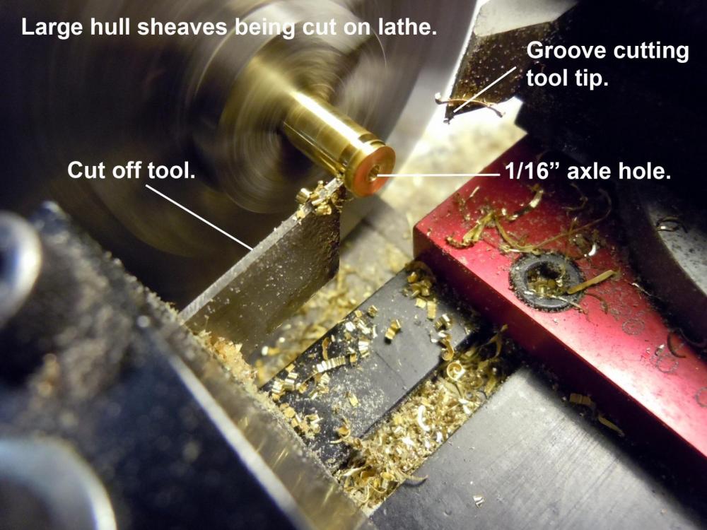


-
David, yes I was thinking the same thing when I saw it and had to read the plans twice. I see you live in Southern Ontario, I was born in Northern Ontario, Marathon at the top of Lake Superior. Now living on the Central Coast of California and do not miss the cold winters at all. Down here the winters are actually warmer than the summers due to the summertime fog on the ocean.
-
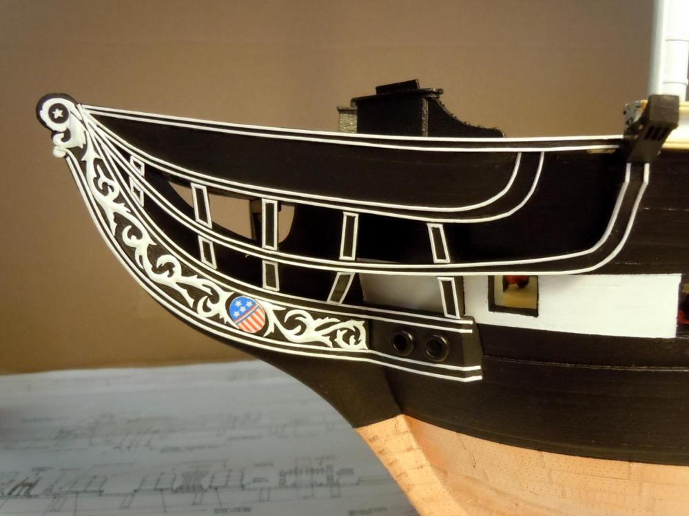
Tom, yes you are correct, the plans show two brace rods, but real ship photos show only one. Both historic and modern. Since I have found other issues with the plans on accuracy I decided to go with the photos. As I have mentioned before one feature on the I-pad versus the PC is the ability to zoom in on photos for detail looks. In the historic photo below also note the difference in the billet head design and decoration with some of the rails not painted white. Being new to ship building I am still trying to sort things out and am learning everyday.
-
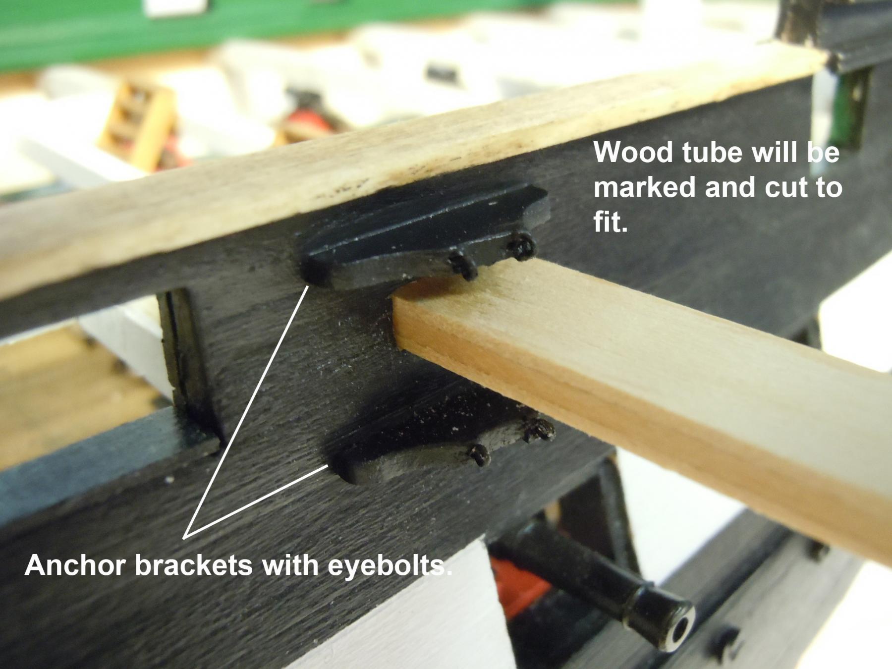
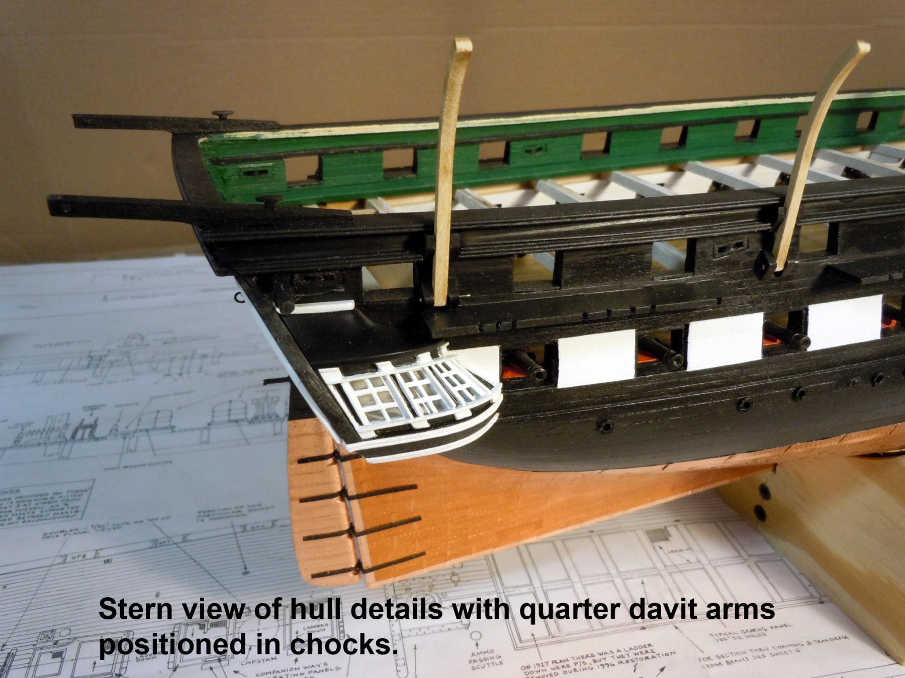
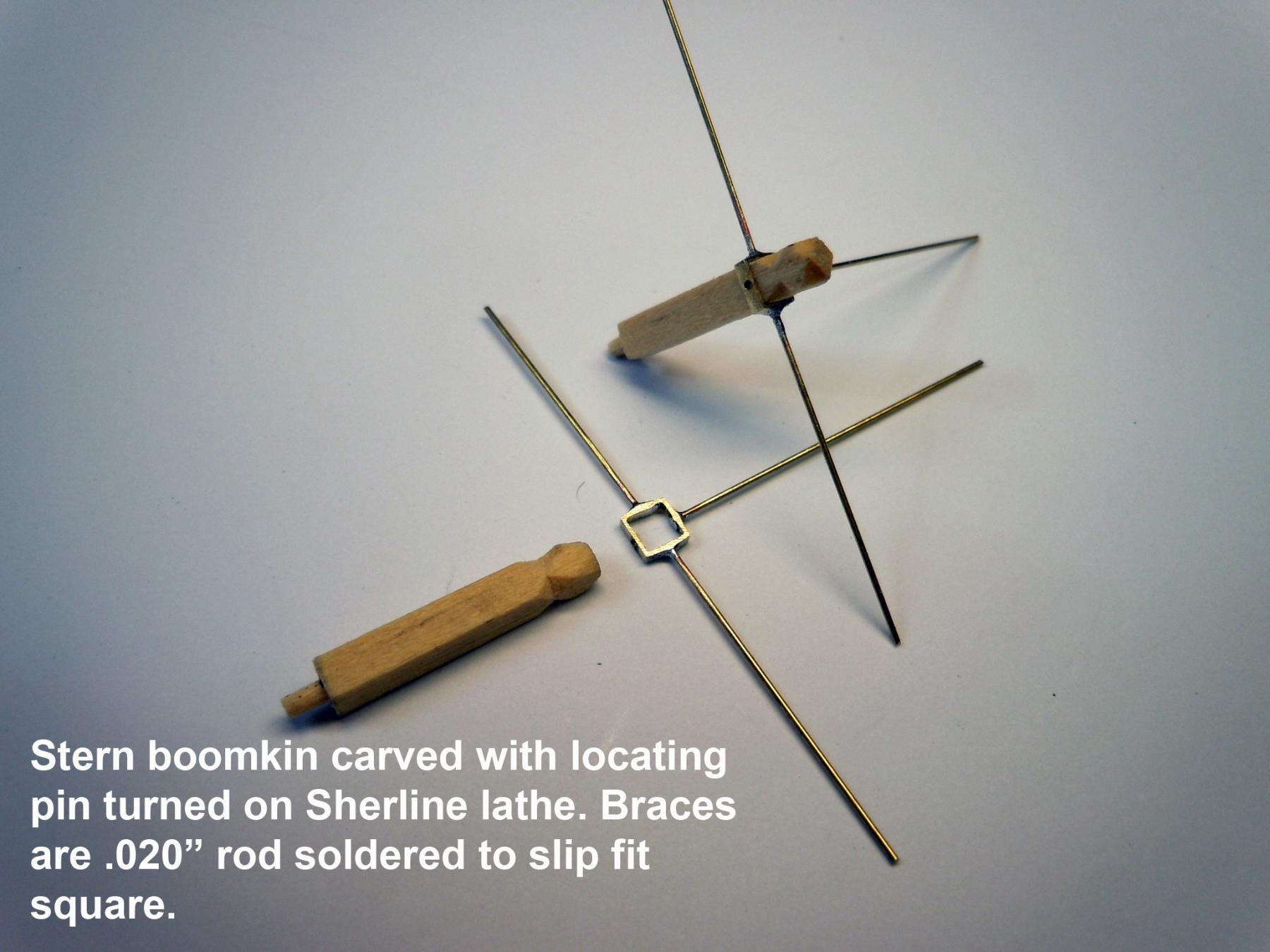
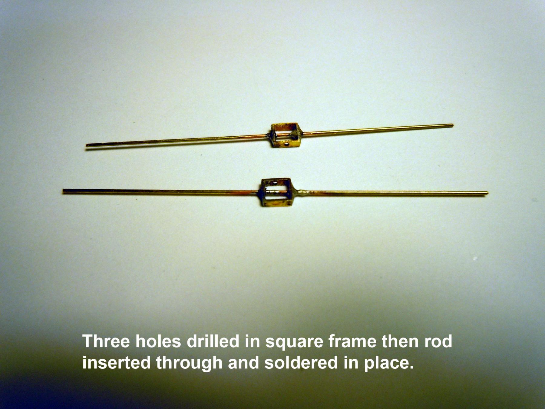
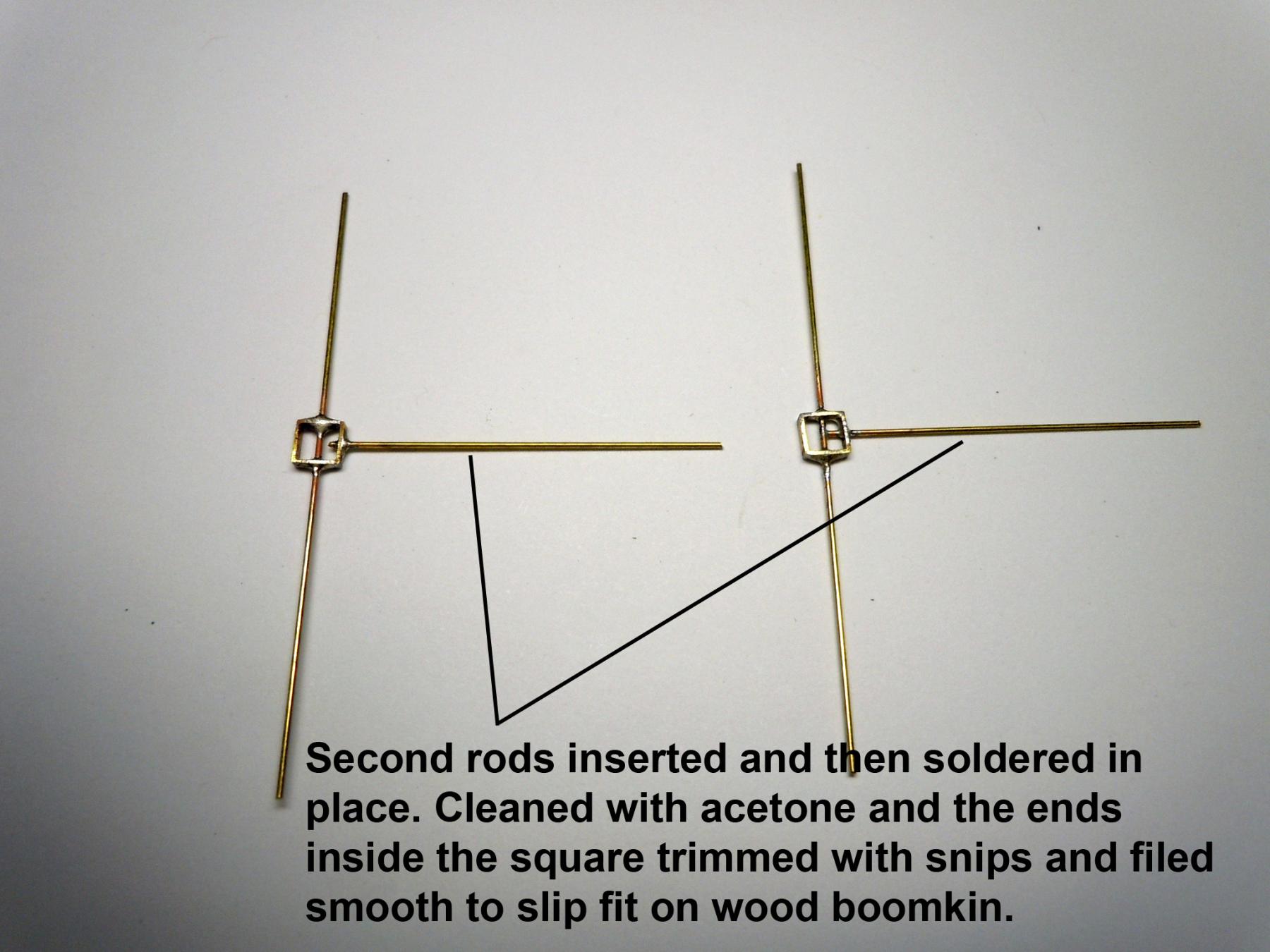
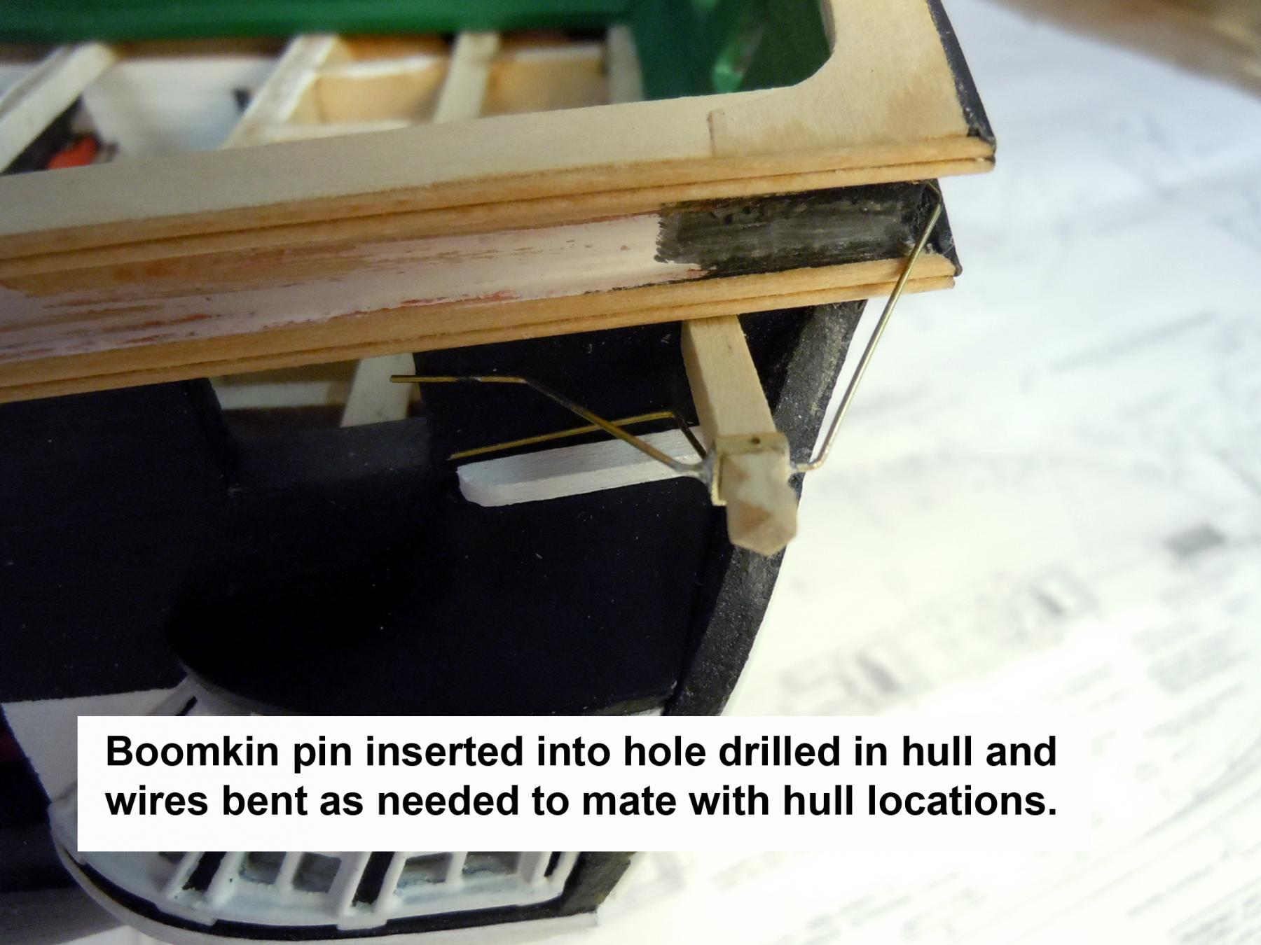
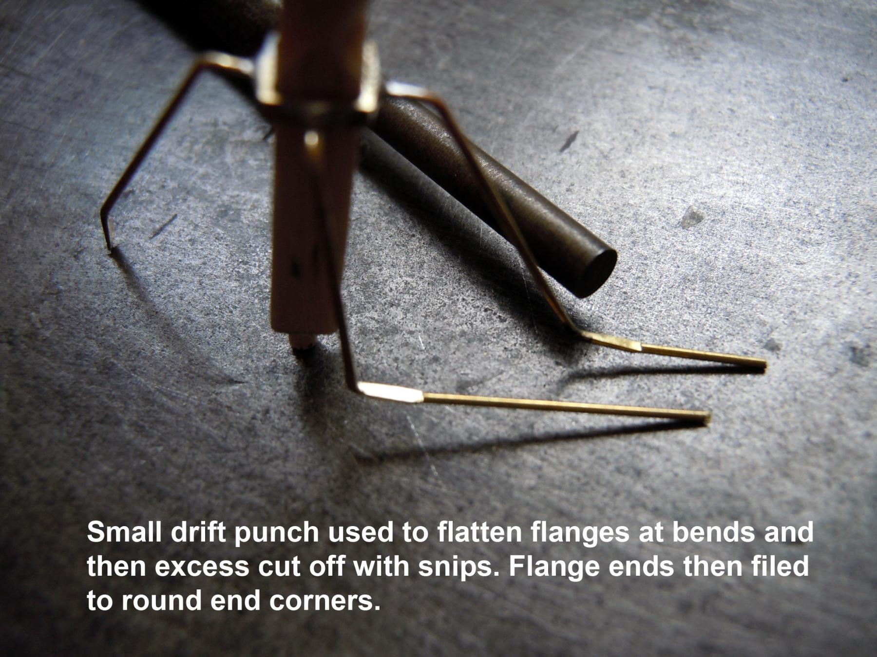
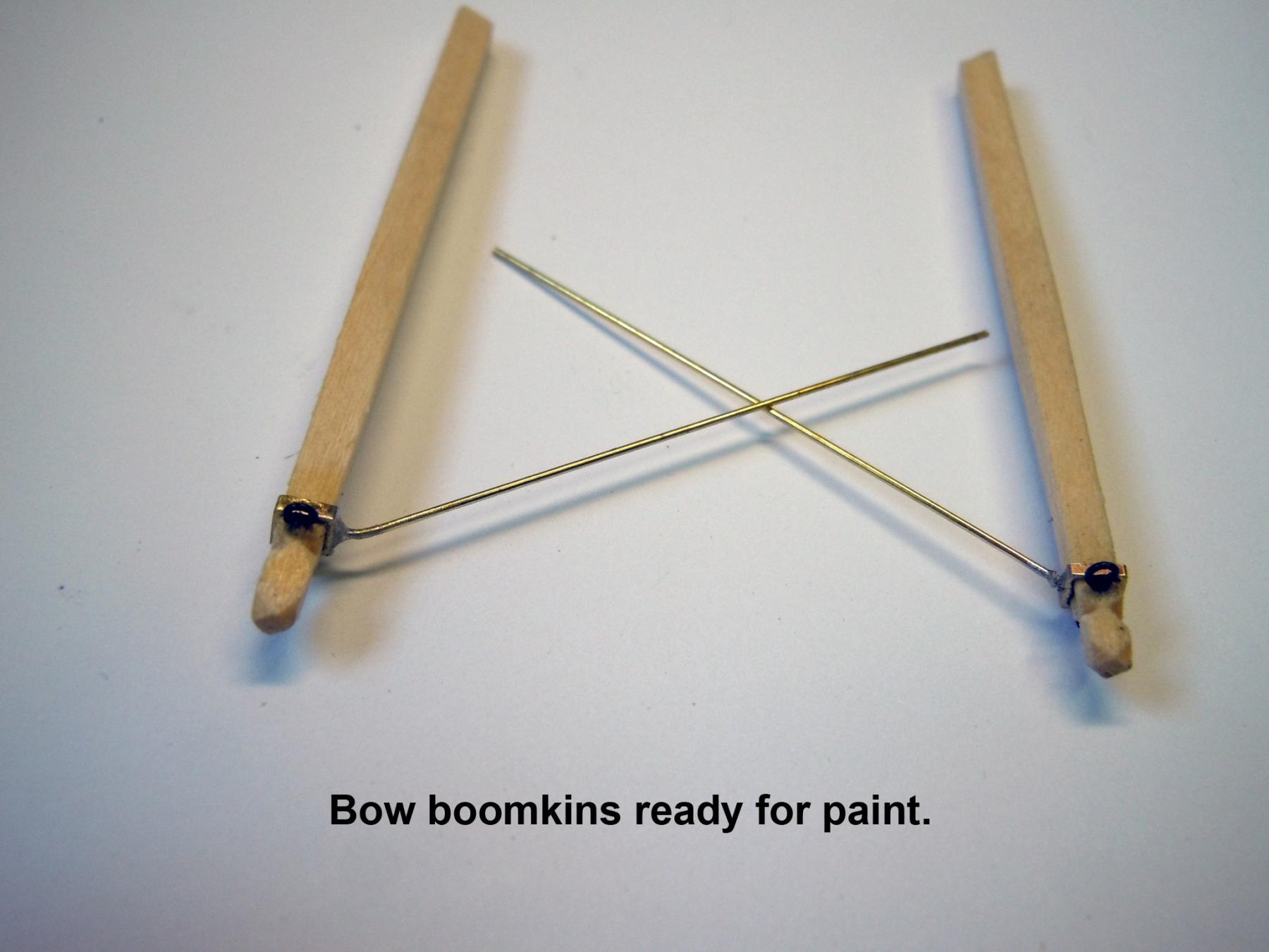
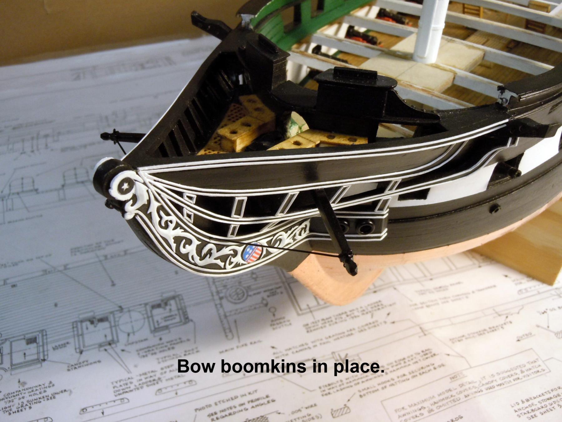
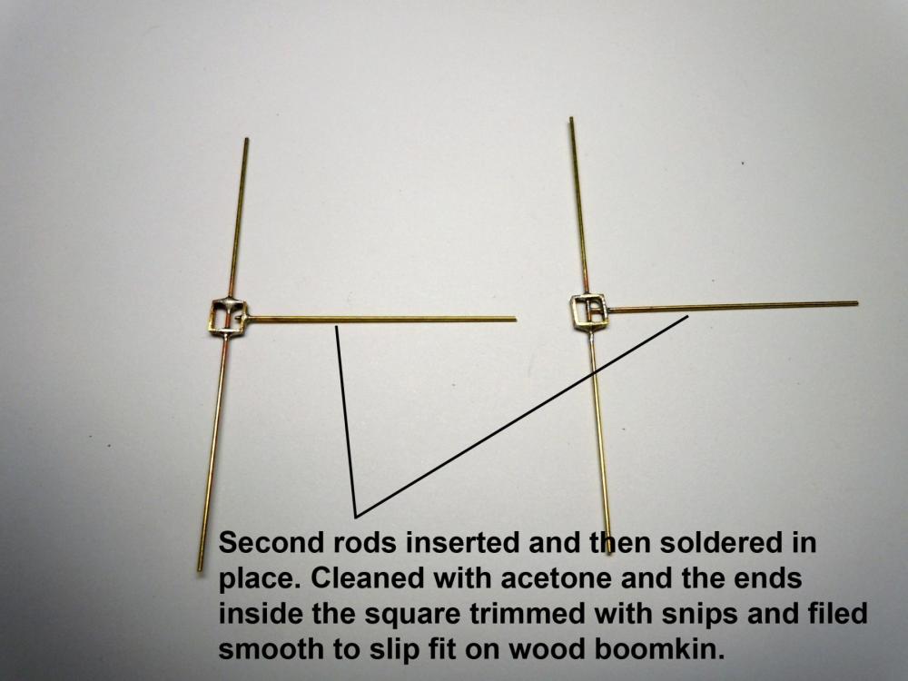
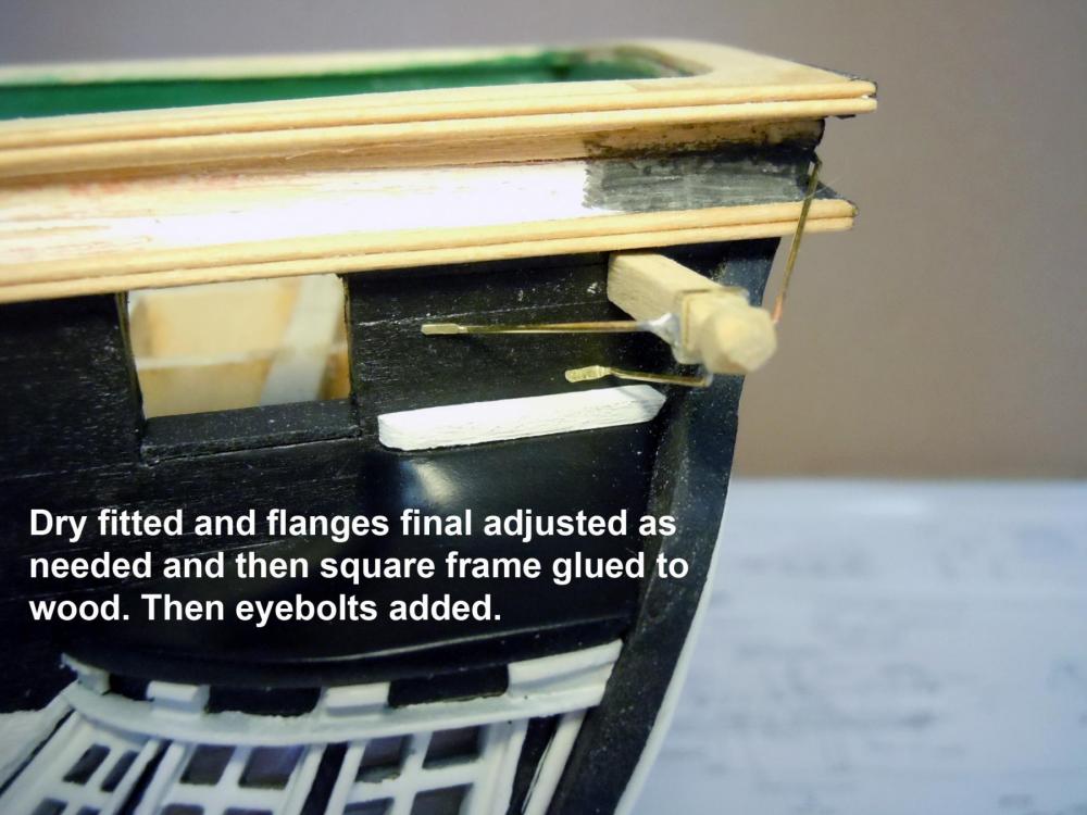
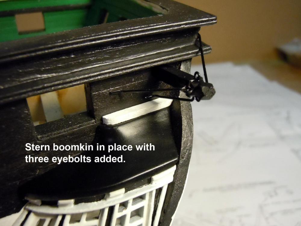
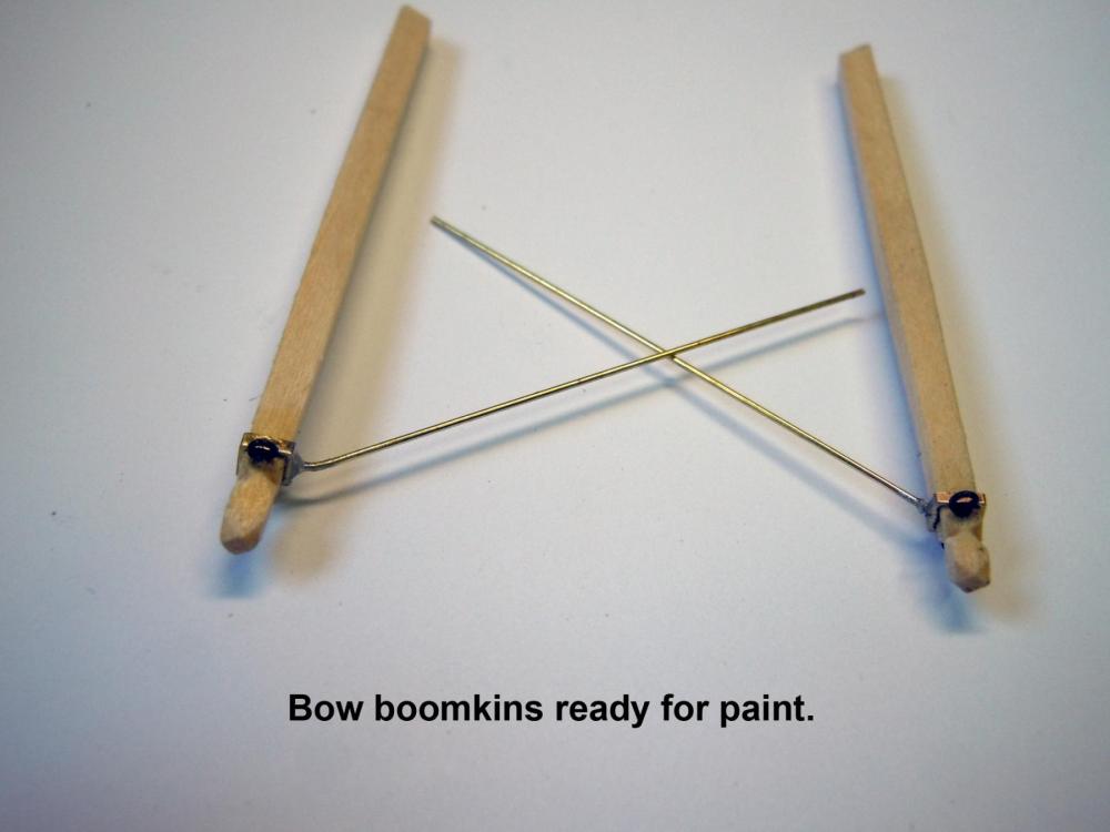
I moved onto the "bumpkins", "bumkins" or "boomkins" or whatever they are called. I used boomkins since it sounds more nautical. First I started at the stern since they appeared to be more complicated than the bow ones. I cut and tapered the boomkins and included enough length to turn a locating pin on the end. I then selected a square tube and cut two slices off the end for frame straps that slipped onto the wood. Next I drilled and soldered three lengths of .020" rod to the frame. Once joints were trimmed and cleaned I positioned the boomkin into the 1/16" hole drilled a in the hull. Next I carefully formed each wire to match the hull surfaces which required removal and bending for each hence the locating pin. When both sides were done the ends at the bends were flattened with a small drift punch to from flanges and the excess cut off. The flange corners were filed round and smooth. They were then final fitted and adjusted and then painted. This shows the final installation at the stern. Then I fabricated the bow ones which were much simpler and the ends cut to match the stem board below the bowsprit. The wire brace indexed into a hole in the black surface between the white strips. Next will be more hull details.


-
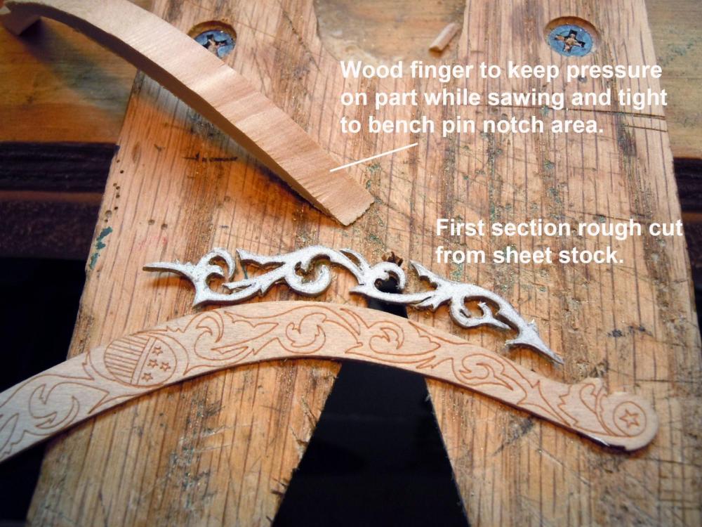
Jon, thanks for posting those nice drawings I am sure they will be helpful for a future builder. The person drawing the plans would have certainly benefited had he had these. Sal, the wooden finger is intended to replace your finger in holding the brass sheet tight to the bench pin and close to the cut. The blade should be lubricated very often to avoid the teeth biting the sheet and snapping the blade. You will know a bite when it happens; but keeping the finger tip close to the cut and tight to the bench pin minimizes biting. The finger is just made from a scrap piece of wood and try to select the wood grain running parallel to the length of the finger for strength to avoid breaking under pressure. I also harden the tip with CA and then sand smooth.
-
Matt, good looking engraving; I look forward to see what you end up with. I have always admired the engraving process.
-
Thank you all for your kind words and I am just glad to share what I can. I moved on and finished up the starboard side created the artwork for the shields and printed out two sets; one in color and one in gray scale which was used as a pattern to cut brass shields to mount the colored set on. Once out of the printer I sprayed them with an initial light coat of Clear Satin and then a second wet coat. This sets the ink and also makes the paper stiffer for easier cutting out. While waiting for paint steps to dry I mounted the carved sections in place very carefully using CA applied with a broken jeweler's saw blade a drop at a time. When glue built up on the teeth I just broke the end off for a new set of saw teeth. Once the sections were glued in place then the shields were added. After all the glues were set both boards were sprayed with Clear Satin for a uniform finish.m When dry then press fir in place. I will let them season for a while before permanently gluing in place. Here are a couple a couple of pictures. The port side closeup and then a starboard side stand off. She now has a face. Now to fiquire out the bow and stern bumpkins and work on the outer hull details. I thought I would just share this for any who wish to follow later or try their hand at this technique.


-
David looking great! I could have sent you a bunch had I known I did not use any of mine that came in the kit. Keep up the great job you are doing. Ken
- 117 replies
-
- 1
-

-
- constitution
- model shipways
- (and 1 more)
-
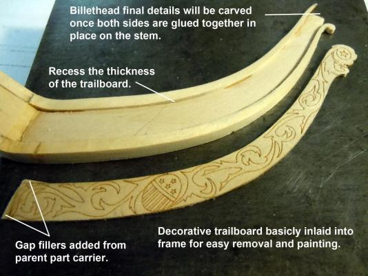
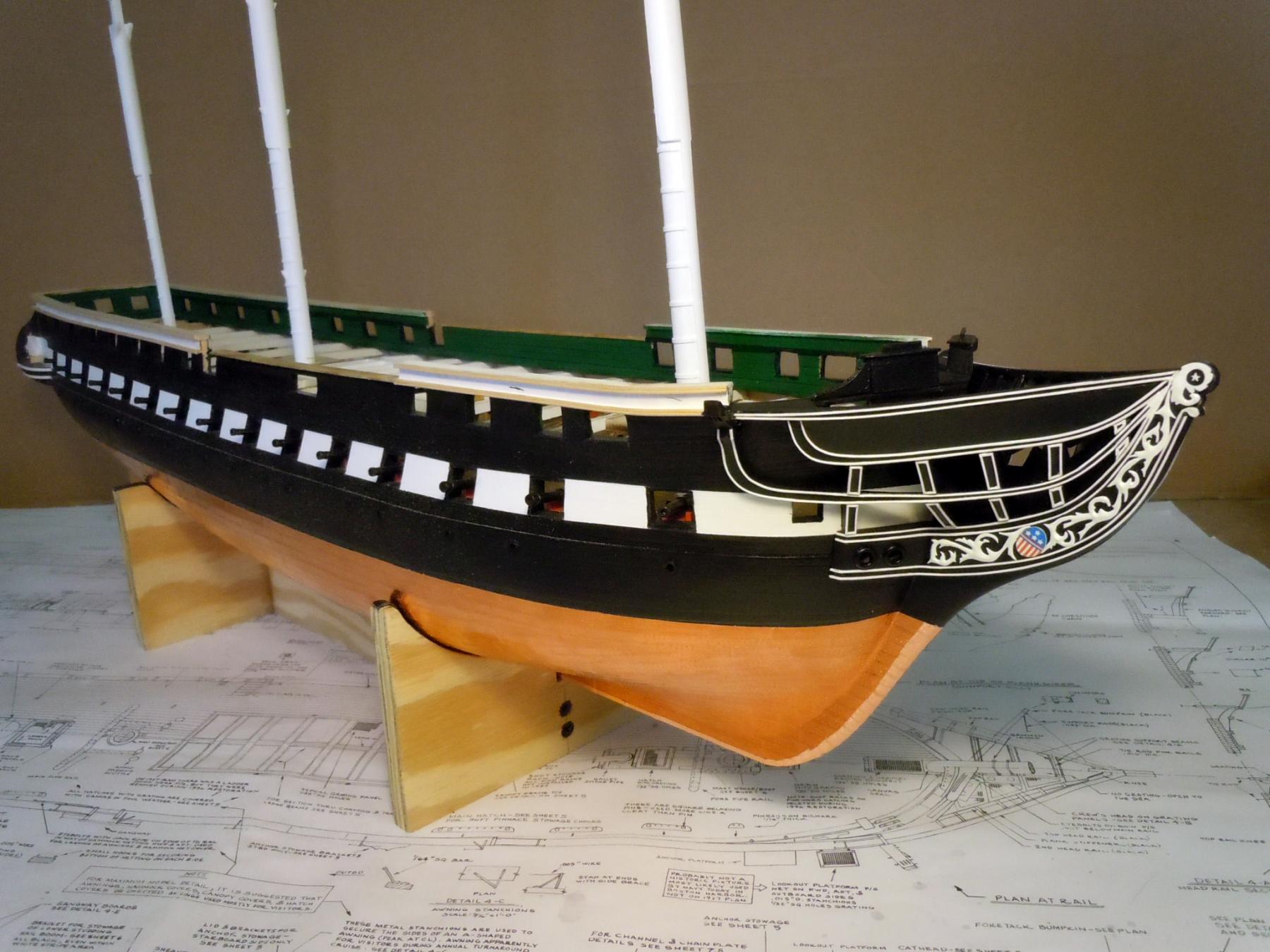
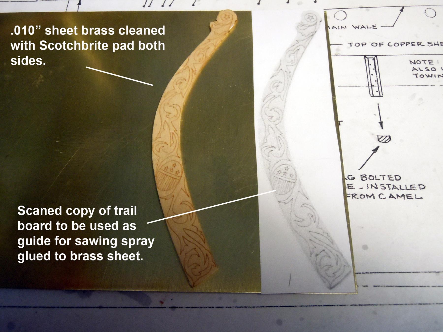
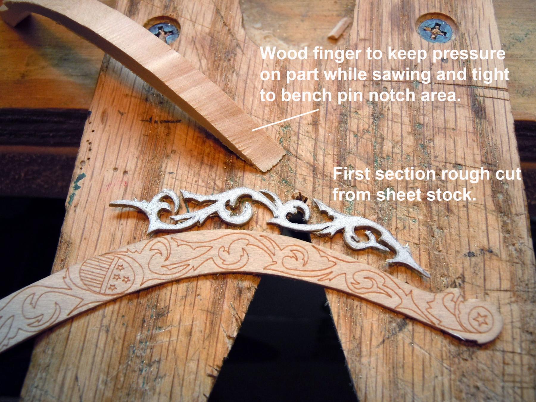
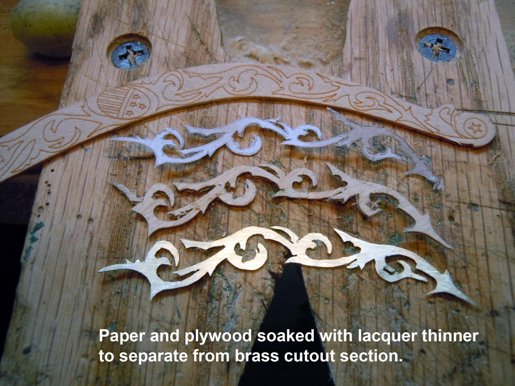
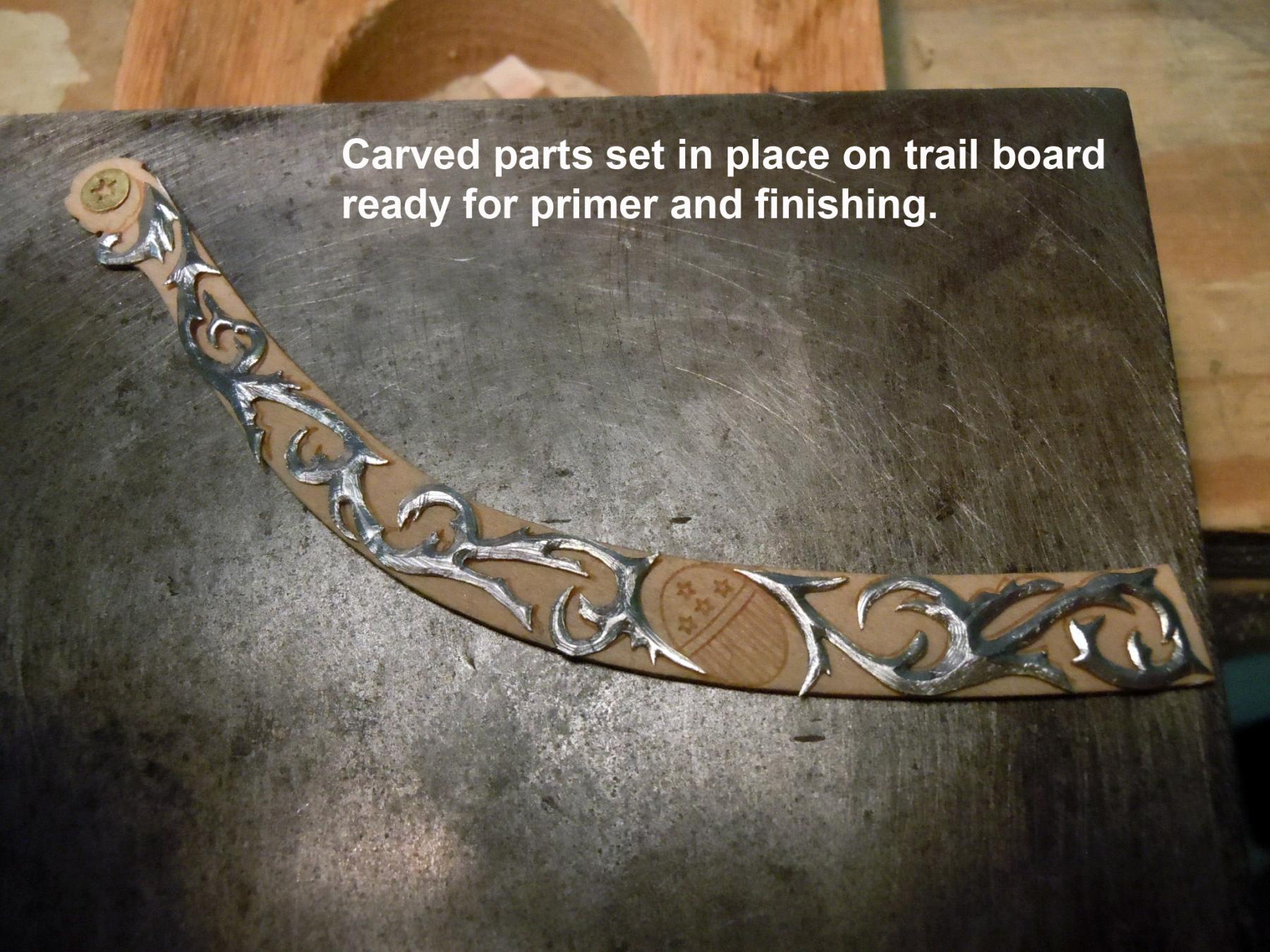
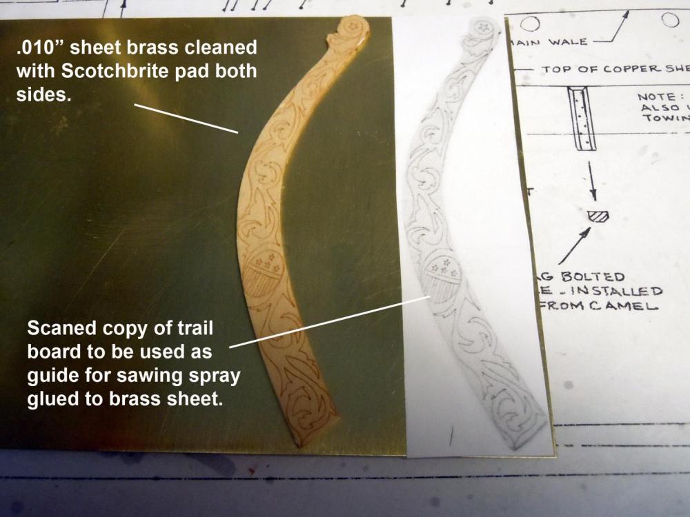
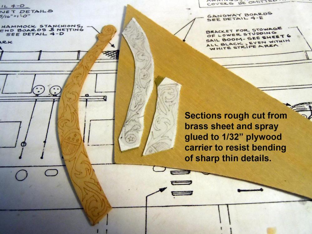
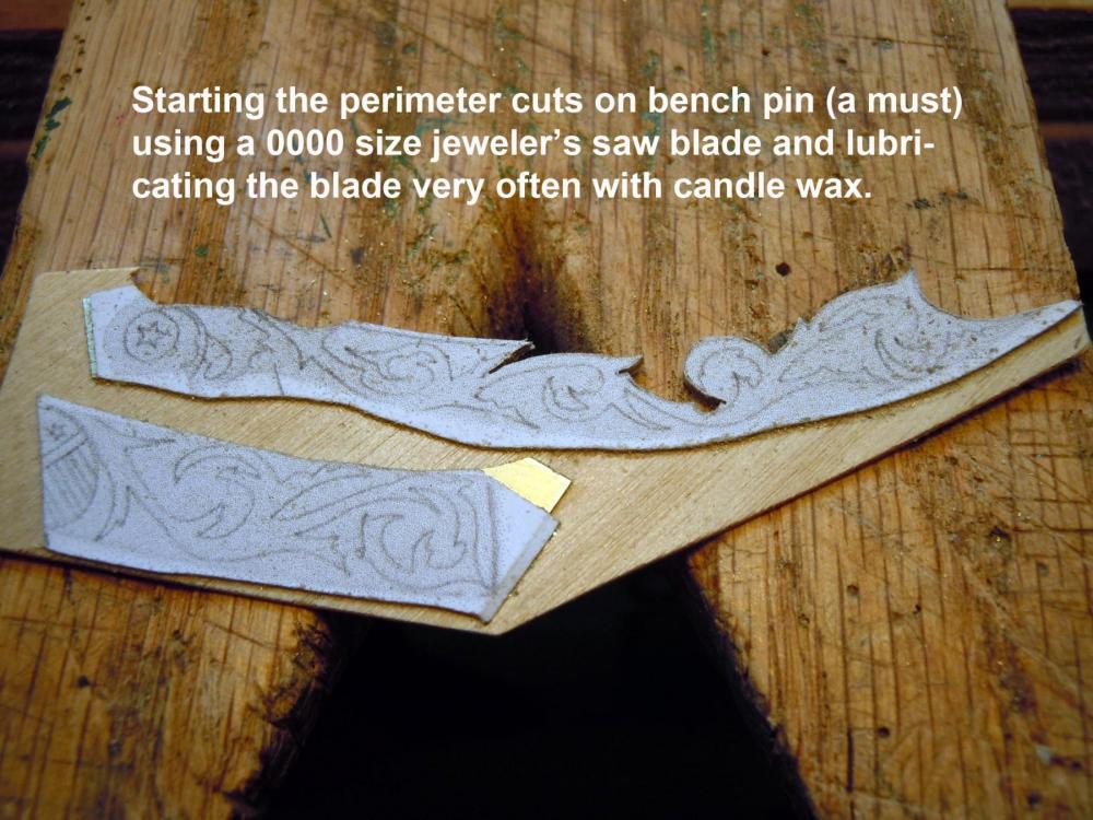
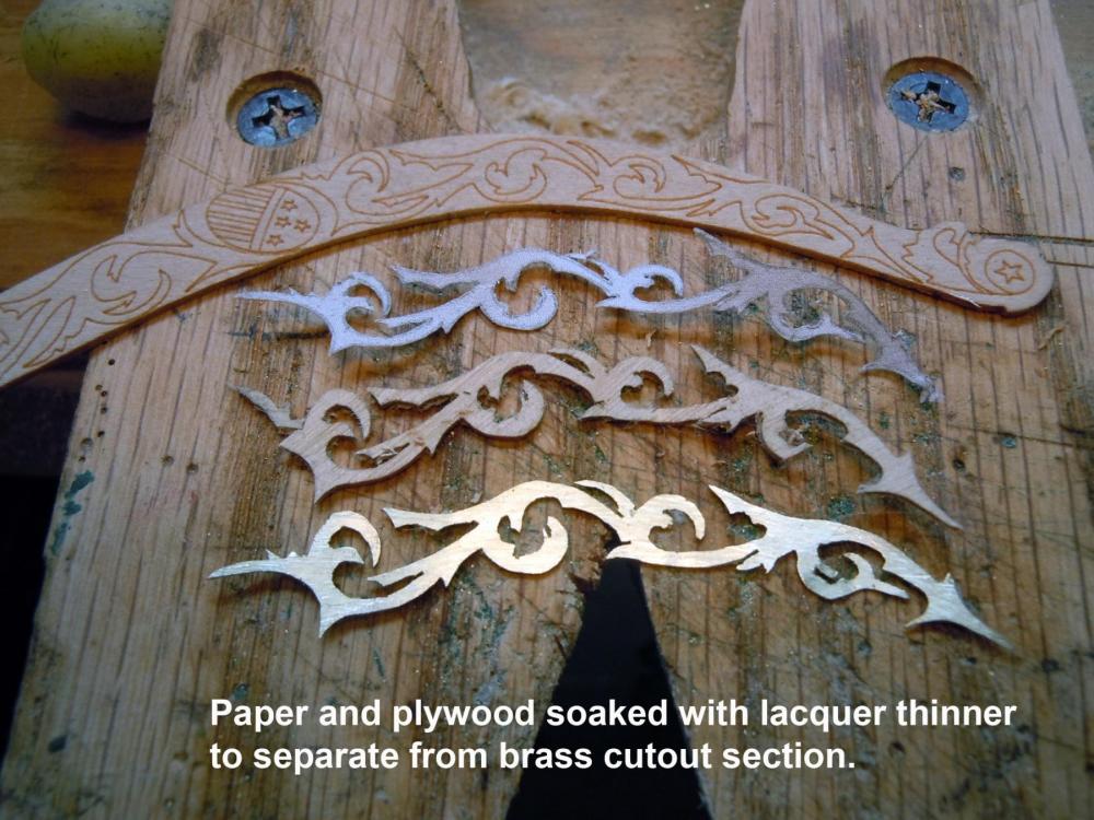
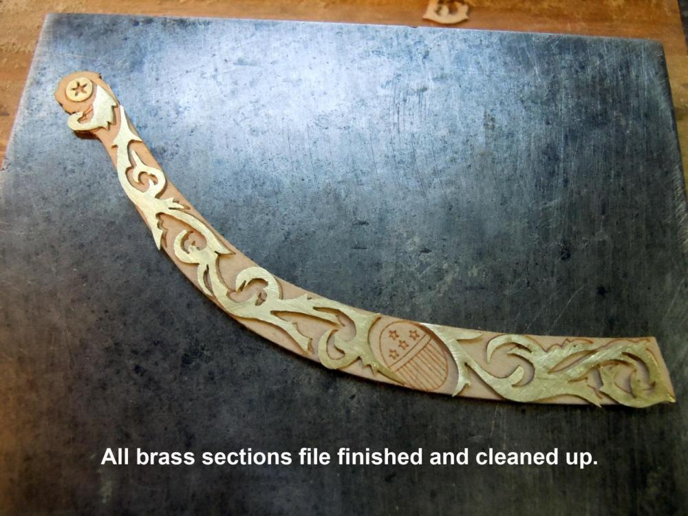
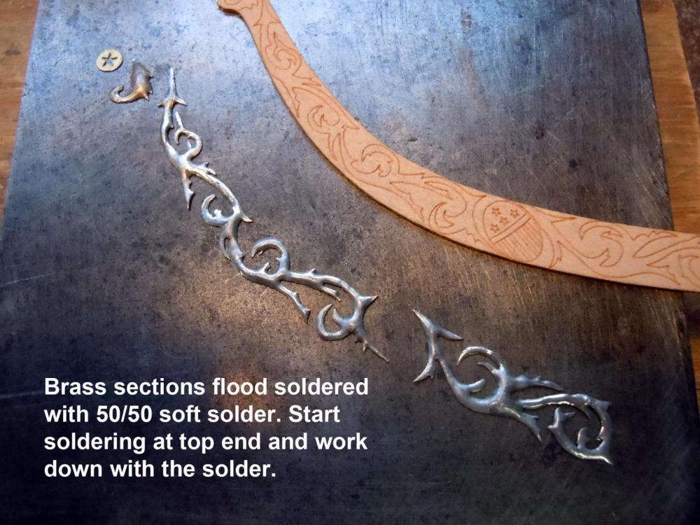
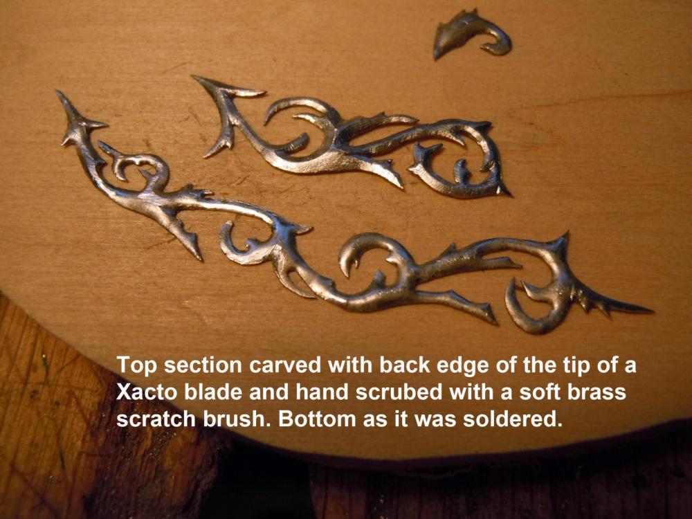
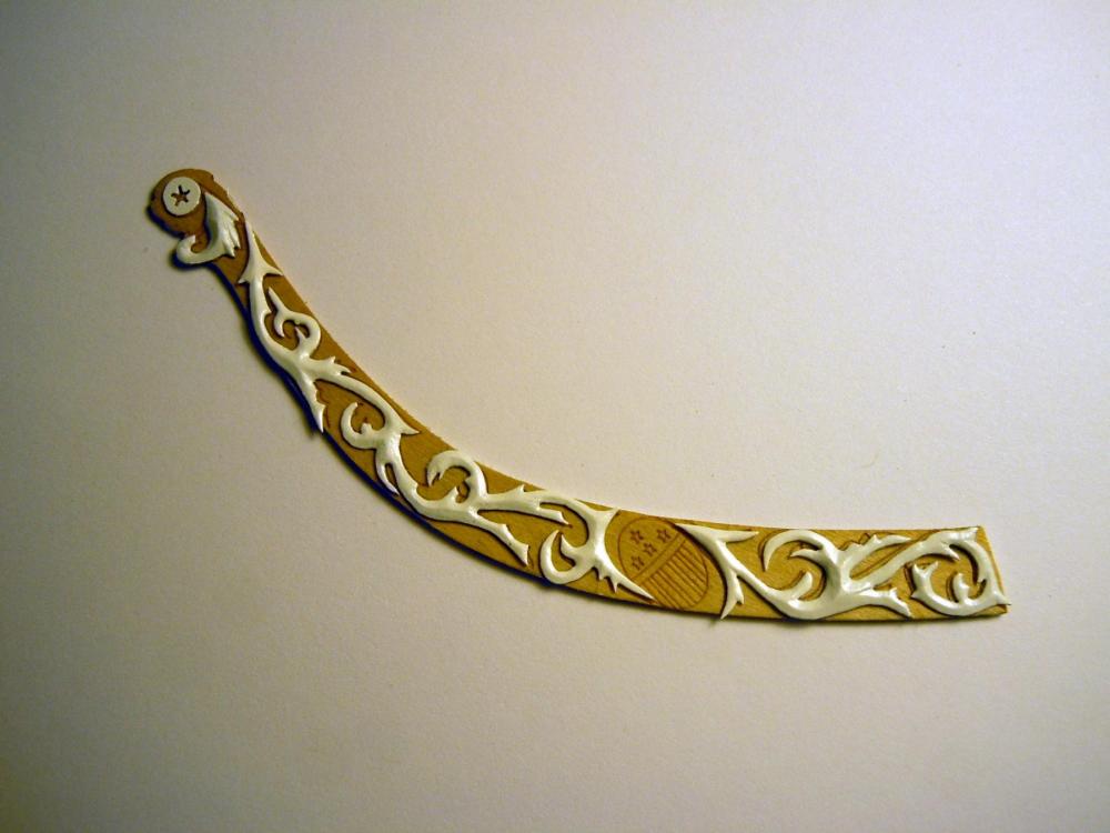
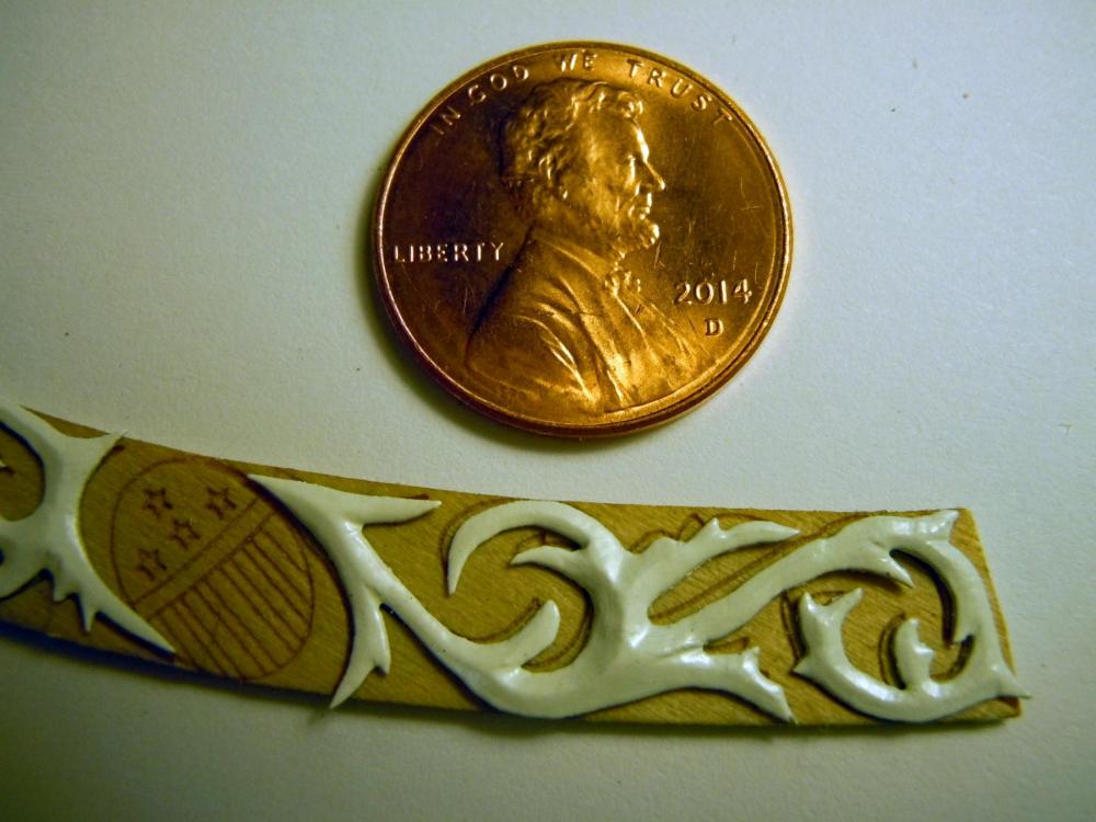
I pondered how to do the trailboard scroll work and decided to go beyond just painting the laser cut pattern which is a fair interruption and slightly distorted to fit the stem. I reverted to my experience with working in brass and scanned the laser cut patterns, cut them out and sprayed glued them to .010" sheet, then subsequently to 1/32" plywood to be sawed out using a jeweler's saw with a 0000 size blade. The plywood provides support and resistance when sawing the small thin pointed details. Use candle wax very often to lubricate the blade and keep clean. Sawing on a bench pin is a must and make a wood finger to keep pressure on the part against the pin when sawing. Unless you have super vision magnification of some kind is a must. Keep the laser pattern close and handy when sawing for reference. Once the sections were cut out the edges were filed and trimmed as needed after soaking in lacquer thinner to remove the paper and plywood. Once ready they were soldered using a 40 watt iron and 50/50 solder starting at one end and working down the part to flood evenly based on the part section. Solder will flow based upon capillary action to bridge evenly as the part thickens and thins. Solder was cleaned with acetone and then again starting at one end and using the back edge of an Xacto blade tip the solder was scrapped/carved to resemble a wood cut. This step must be done with care to avoid having to re-solder if a mistake is made. Using a light close and at an angle to the part really helps since the surfaces will shine once scrapped with blade. Work slowly and carefully. Here is a sequence of pictures: These parts are great candidates for photo etching and would be a great addition for an upgrade kit. The star center was drilled and the blade inserted and the points of the star sawed, then a sharp blade cut the final star points cleanly. This needs a steady hand. One suggestion also is to take a fine half round file and grind the round side flat/tapered to the point to file into the tight intersections. The wood finger is a must as well; sometimes you just have to make your own tools to get the job done. I will now cut the opposite side then work both sides to completion.

-
Jon, just another of the kit's mis-judgments I saw the wrap around to the hawse plate but the kit trailboard when anchored at the top with the round portion on the bow stern it only extends down on the flat surface and would lay even shorter if I had not added the hawse plate like I did. The scroll work would have to be extended beyond the laser part and bend to fit on the hawse plate almost touching the forward hawse pipe. Based on my hull it would be another 5/16" on the hawse plate. I will cross that bridge once I get there; I am still thinking of the best way to the trailboard which originally was carved raised wood decoration. Just another of the kit's surprises that they do not charge extra for.
-
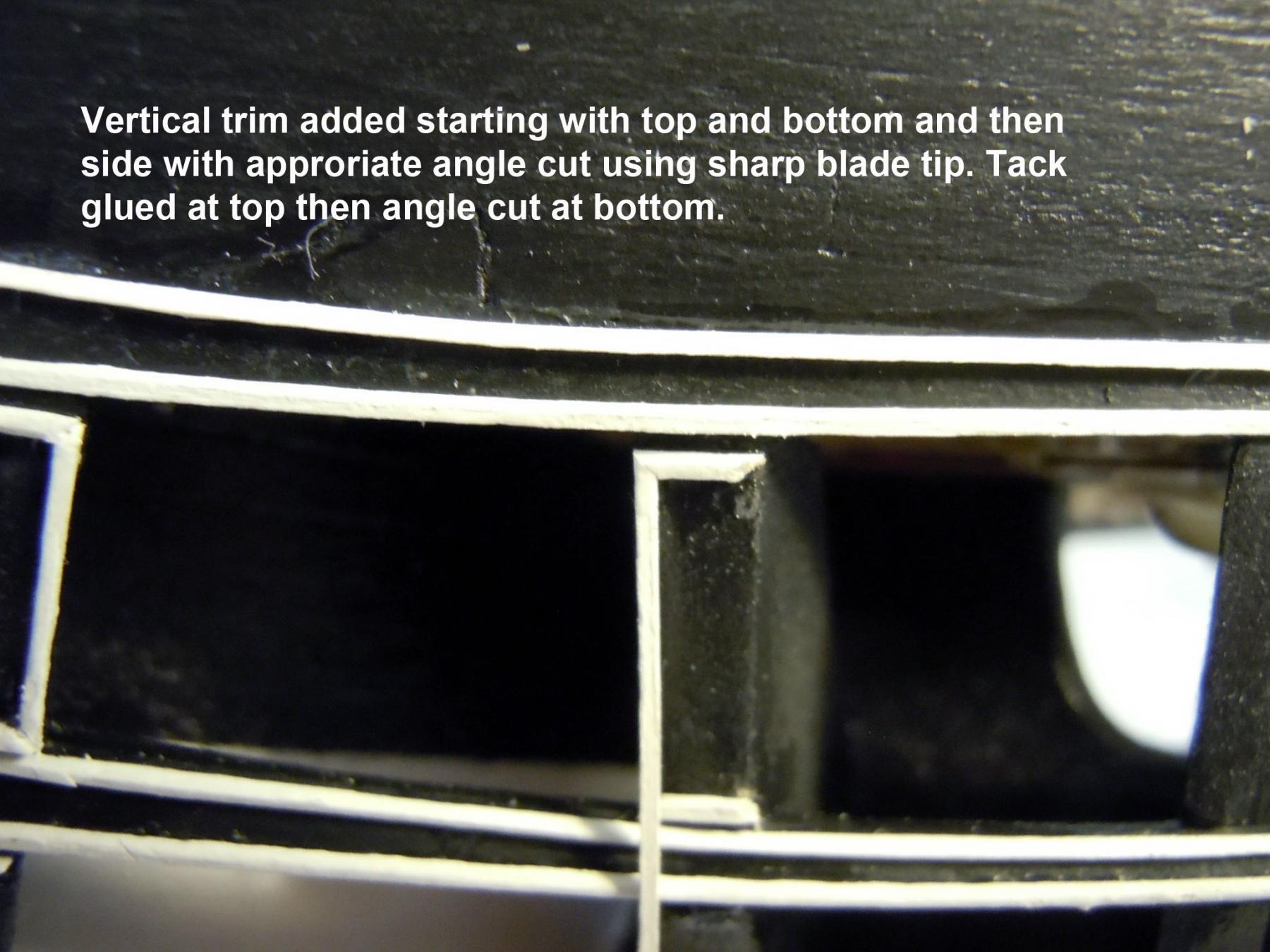
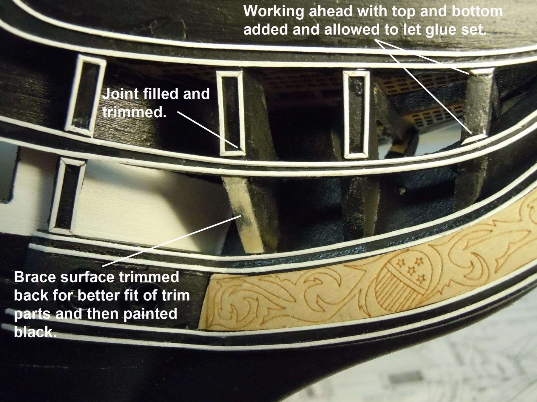
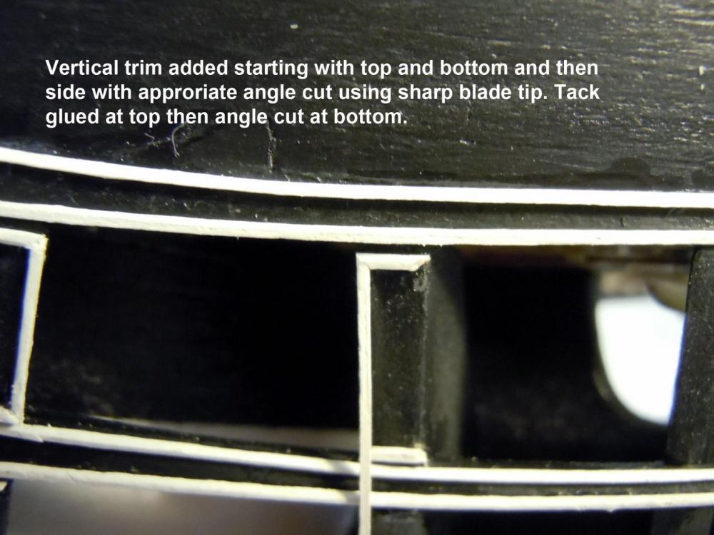
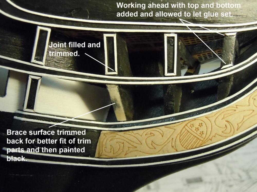
I anticipated the possible delay and started to move forward. The modelling god's are up there laughing at me; I thought I had #8000 somewhere so I started searching back through my boxes of stock and sure enough stuck between two sheets of 1/8" sheets was one partial pack with 4 pieces left in it much to my delight. They were painted sanded and painted again with the 60/40 mix of white paint and dried in the sun. Ends were cut and set in water to wick up the ends and the long stem pieces added first around the trail board. Then the short pieces added; first the top and bottom parts and then the sides with all cut at needed angles. The second brace from the hull required careful trimming to have a good fit to the rail trim. I dry fit all the parts first before gluing just for this reason. I finished the starboard first and these do require a bit of patience and I would highly recommend the use of the rigging tool and sharp blades for trimming. These do not need to be wetted. The #8000 was great to work with but tiny stuff to fit. Once all were dry and set the area was sprayed with Satin Clear to even up the finish and eliminate the CA glare areas. TIP: For those who break jeweler saw blades save them the ends with teeth make great CA applicators in tight spots and glue build up can be just broken off with two sets of pliers. Here is a sequence showing the steps and the finished results; not perfect but good enough. Next to move over to the port side. If you listen real close you can still hear the modelling god's laughing at me.

-
Kurt. Midwest replied 8:15 (pacific),#8000 will be in stock in 1-2 weeks.
-
Kurt, thanks for the feedback! What do you know about Northeastern Scale Lumber? I have cross referenced and found item # HOSCAL2211 which is HO scale 2x2 basswood, no dimensions on site. 14 pcs per pack at $3.65. Jon, I have not used Boxwwod so you may just have to experiment on it's flexibility when wet.
-
Jon, I have years of experience working with every plastic known to mankind while I worked at Rubbermaid in product and business development. Polystyrene will yellow overtime when exposed to UV light from the sun, even ambient light in a room or from florescent light bulbs. It is at times a challenge to form as a flat or half round when gluing with CA and should be cleaned with acetone to remove residual mold release used in the extrusion dies. Chartpak tape is also used and comes in very small sizes and is basically a colored vinyl tape and should be CA'd once in place. This is real old school stuff. Free hand painting was out of the question at this scale.
-
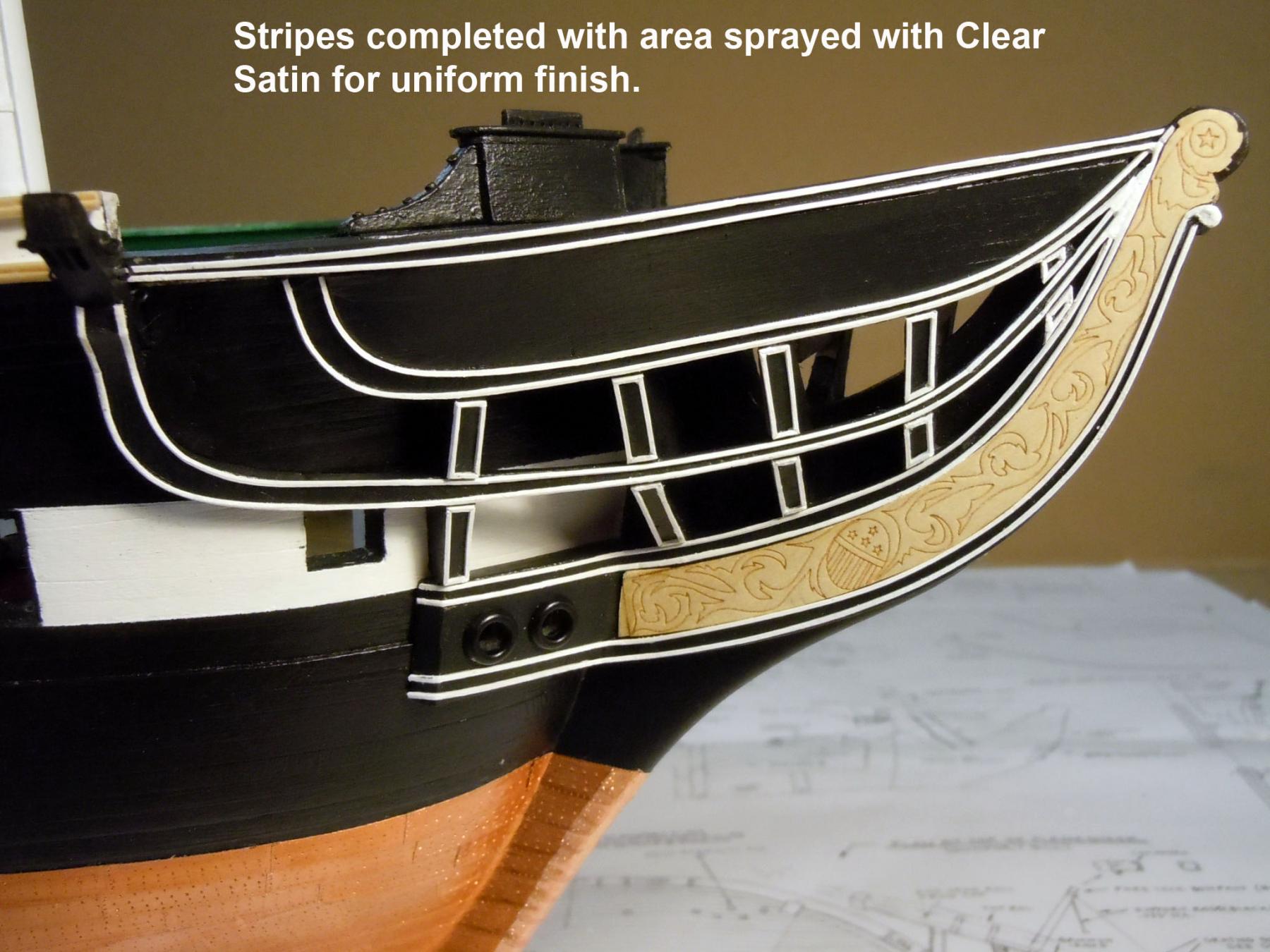
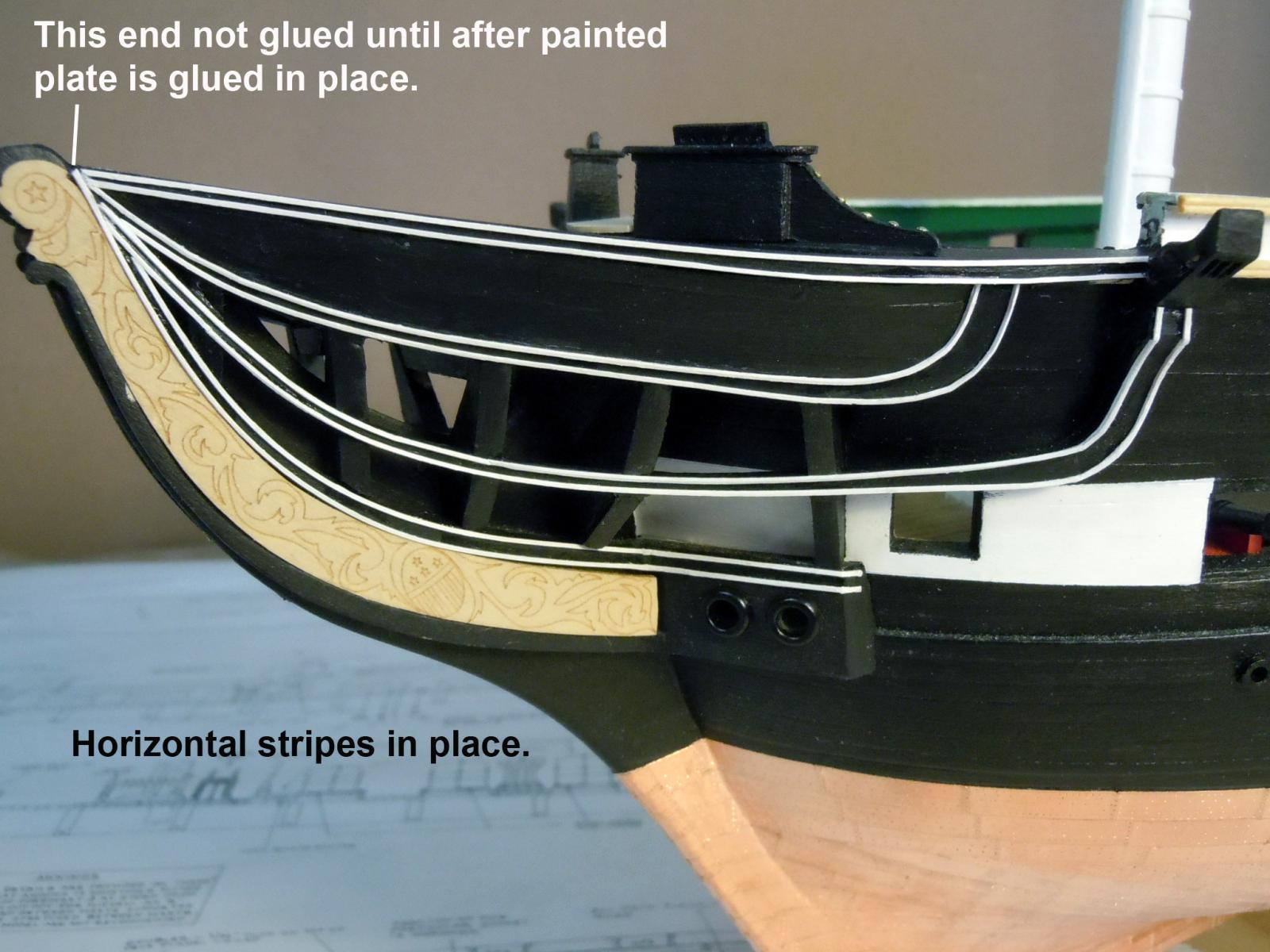
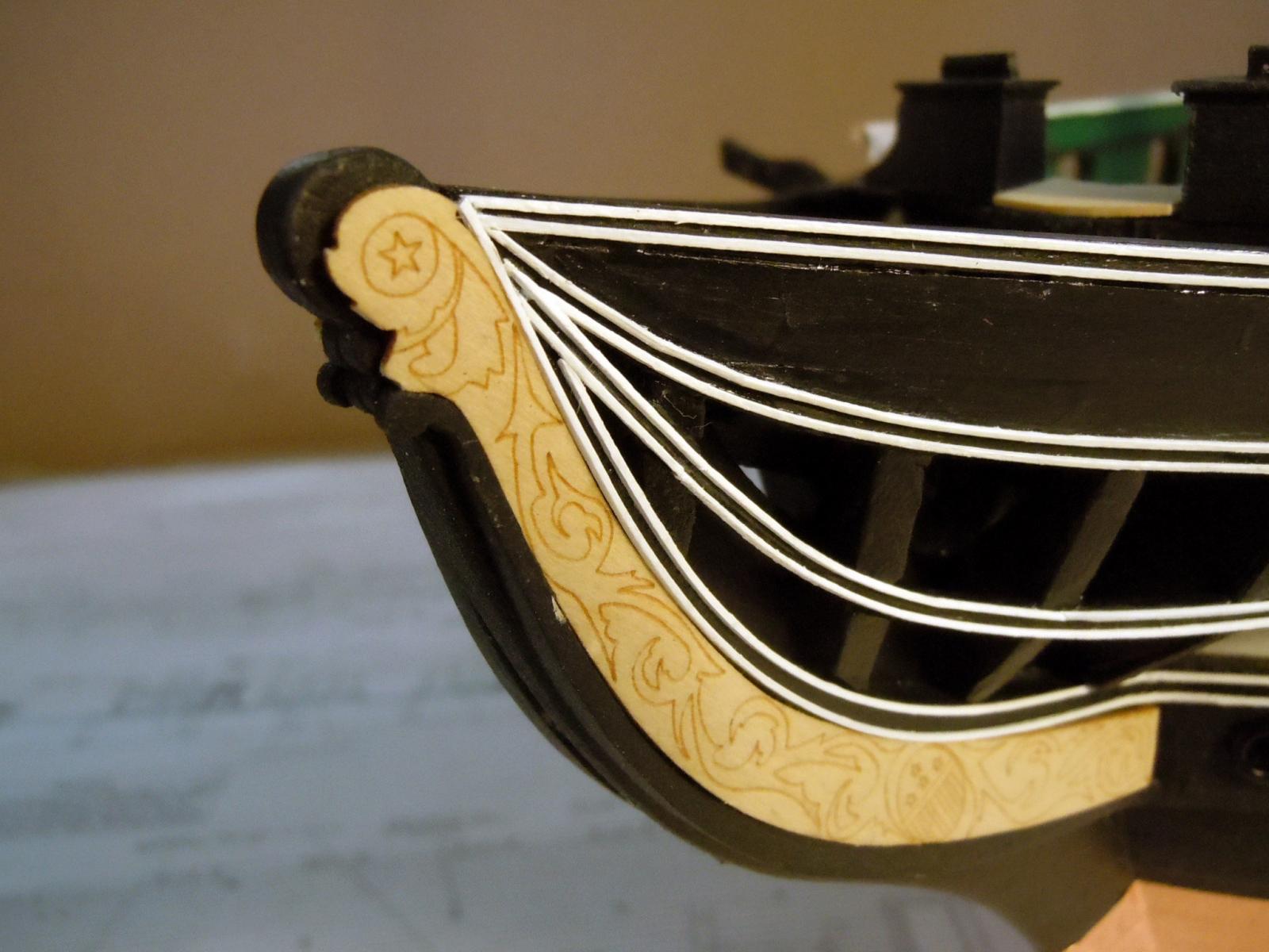
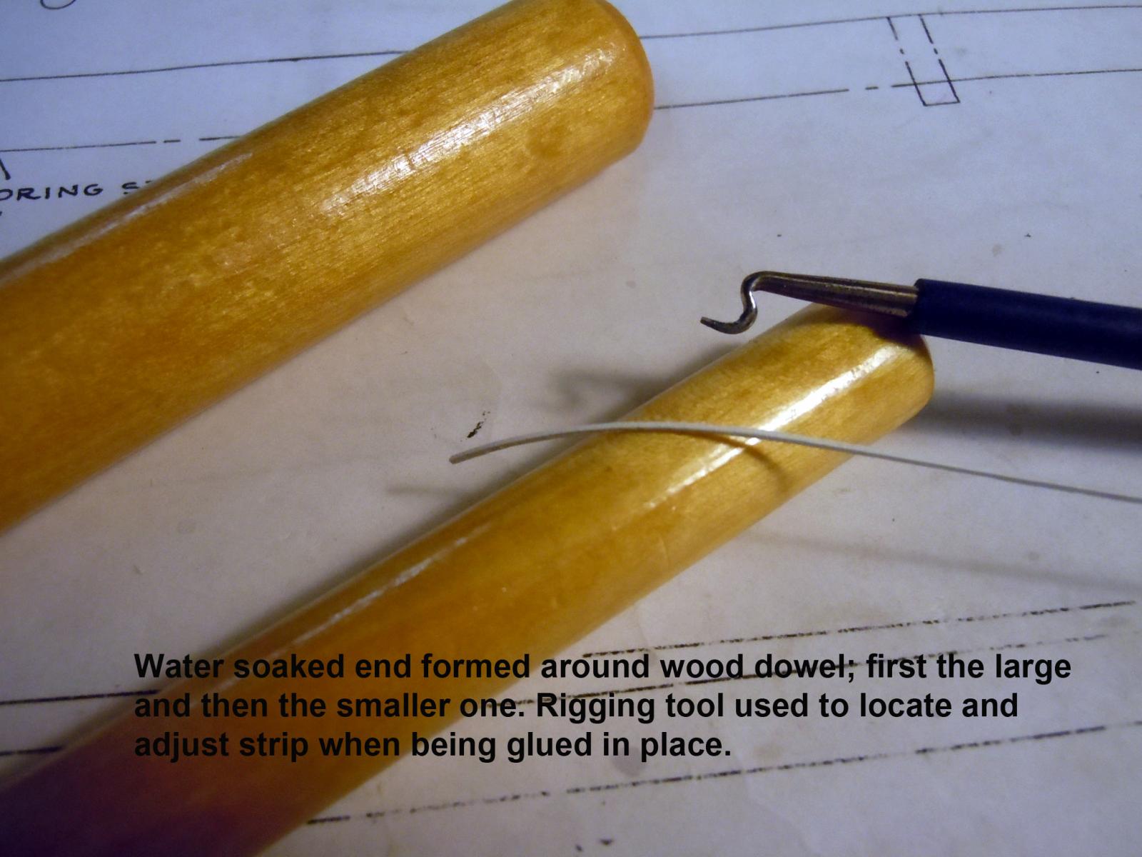
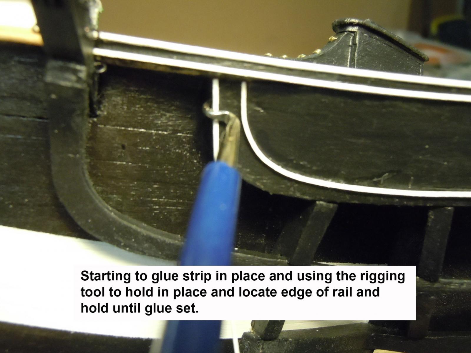
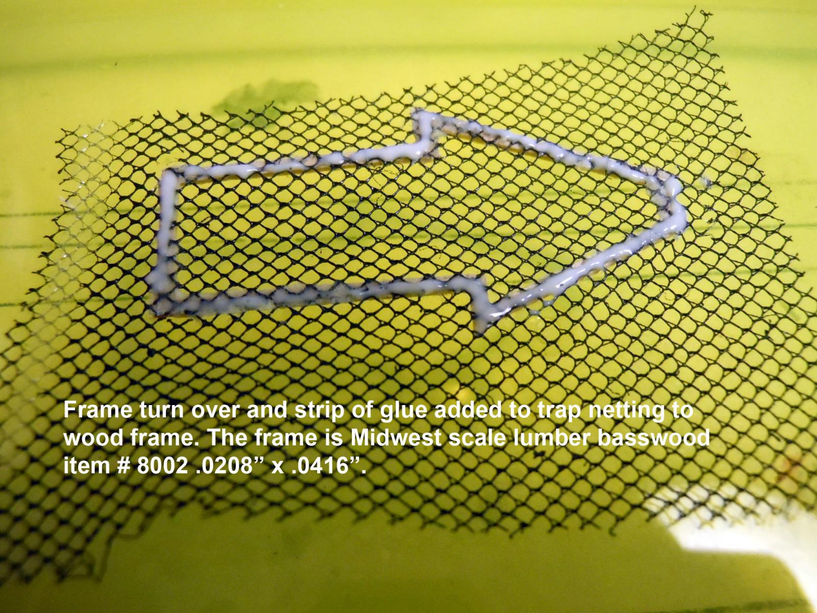
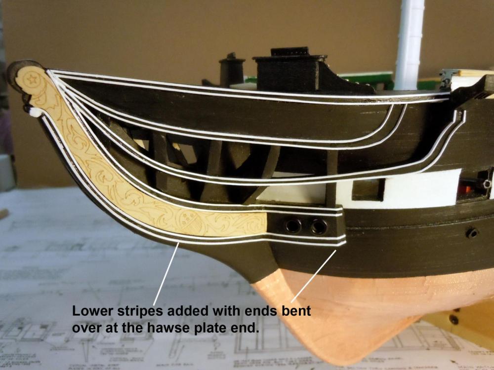
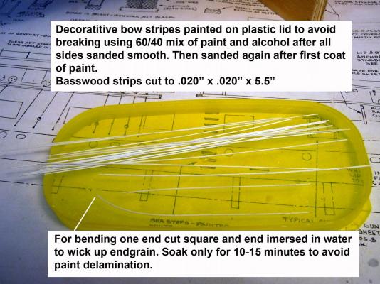
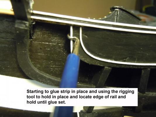
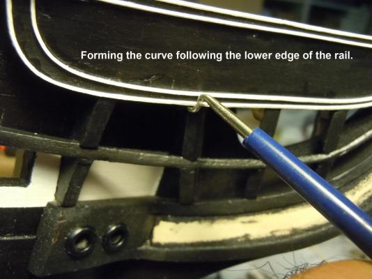
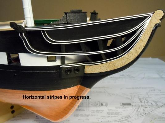
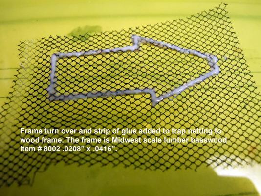
After exploring various alternatives to doing the bow stripes I fell back on my WWI airplane building experiences and went looking for my stock of Midwest Scale Lumber. Of course I was out of the item I needed #8000 (.020" x .020" x 11") checked on their website to order and the item is "Temporarily Out of Stock" so I inquired by email when it would be available again. In checking I found item #8002 which is .0208" x .0416" and I had 5 pieces; so I split them down the middle cutting them in half. One TIP here is to wet with water the strips before cutting with water on finger tips no need to soak. This avoids brittleness and breaking. Next I carefully sanded the cut edges and painted them with 50/50 mix of White paint and alcohol sanding between coats until smooth, no primer. This mix penetrates the wood and the alcohol makes the wood more limber for bending. However, to really bend the curves once the paint was set I cut the ends and set the cut ends in a tray of water to let the water wick up the end grain of the wood. Only wet ends for only 10-15 minutes based on kit paint; too long will delaminate the paint. To form the bends I used wood dowels working from large to small and formed with the cut edge to be the contact glued edge. I started at the cathead end and worked from top to bottom using a rigging tool to assure forming, contact and edge alignment and allow the spring in the wood to form the curves as well. Do not press the wet wood too hard with the tool or you will dent. Using CA do not let fingers come in contact use the tool and move the tool slightly while glue is setting. Only add the CA when you are happy with the fit; at this size you have only one shot. Also when starting and ending allow overhang and slowly and carefully using the tool bend the corners over on the ends. Since I ran out of strip stock I worked both sides to the same point. Hopefully, I will hear back from Midwest tomorrow. Here are some images that hopefully explain the process as well. Note the ends are bent over the ends at the cathead and hawse plate. Now to see if I can carefully cut some strips from the ample supply of #8003 .0208" x .0625" x 11" to finish up the stripes.


-
Weathering a copper hull
xken replied to Ray1981's topic in Painting, finishing and weathering products and techniques
Try this it might work better and not smell as bad. My wife uses this all the time on her copper garden artwork. Here is a link. https://www.jaxchemical.com/jaxshop/shopexd.asp?id=19 -
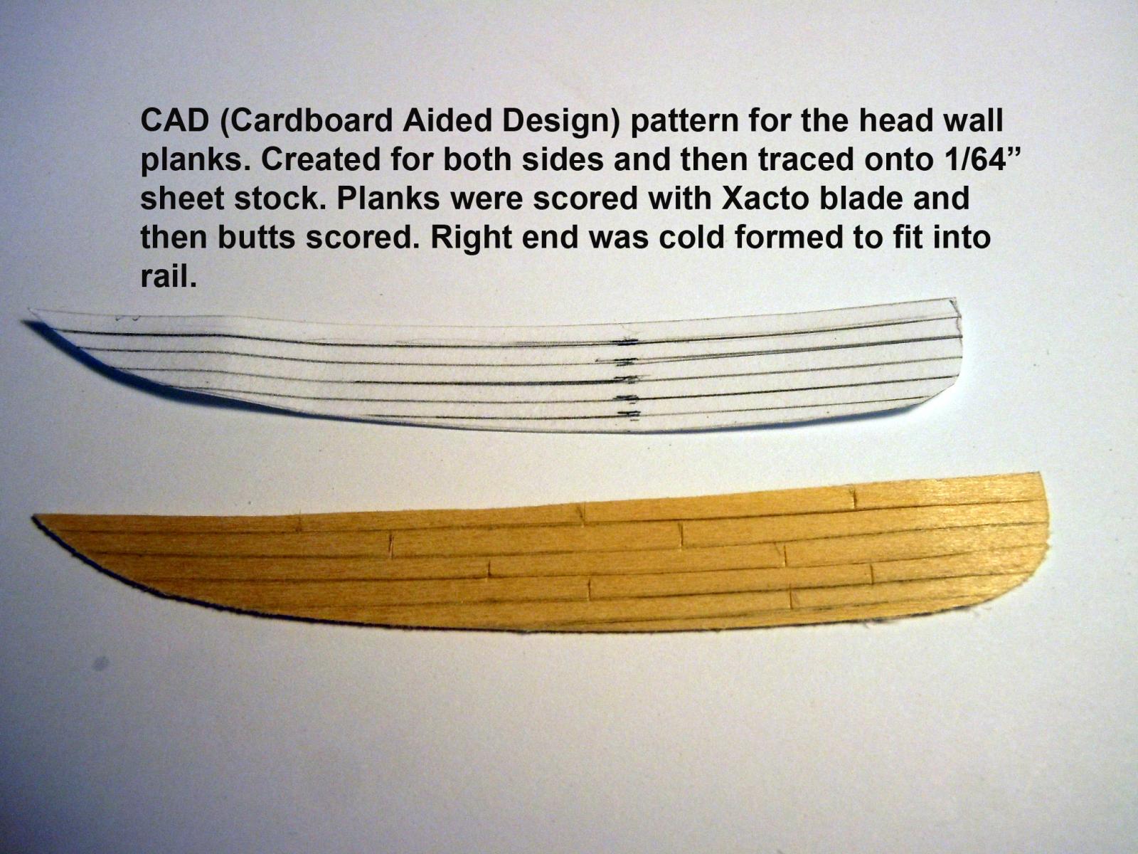
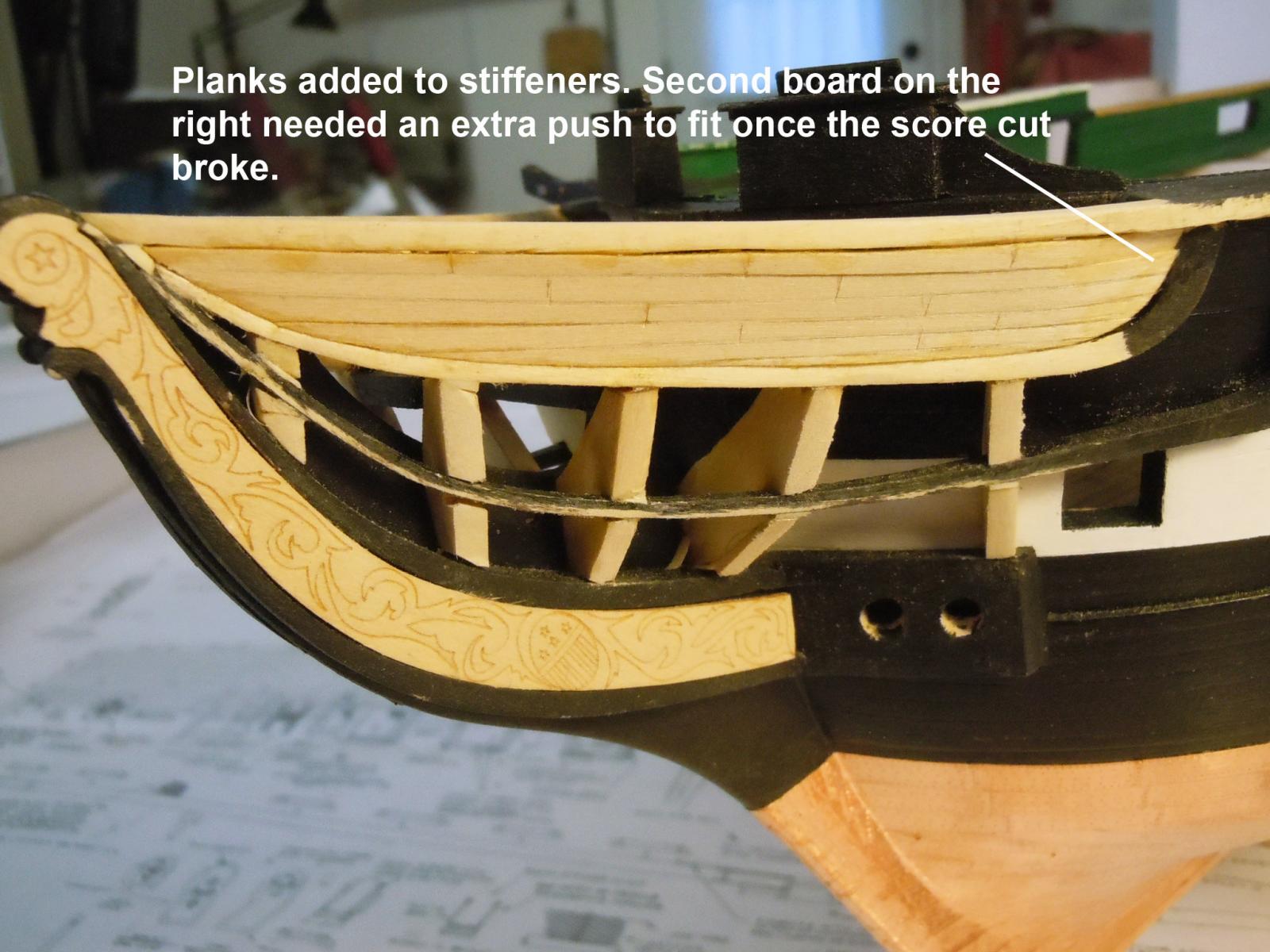
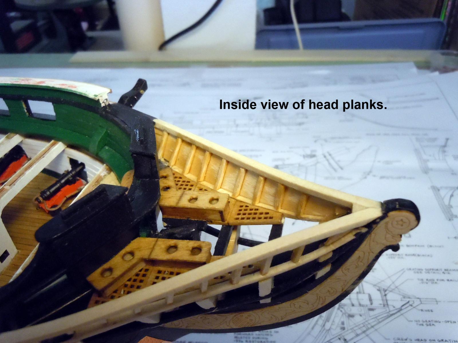
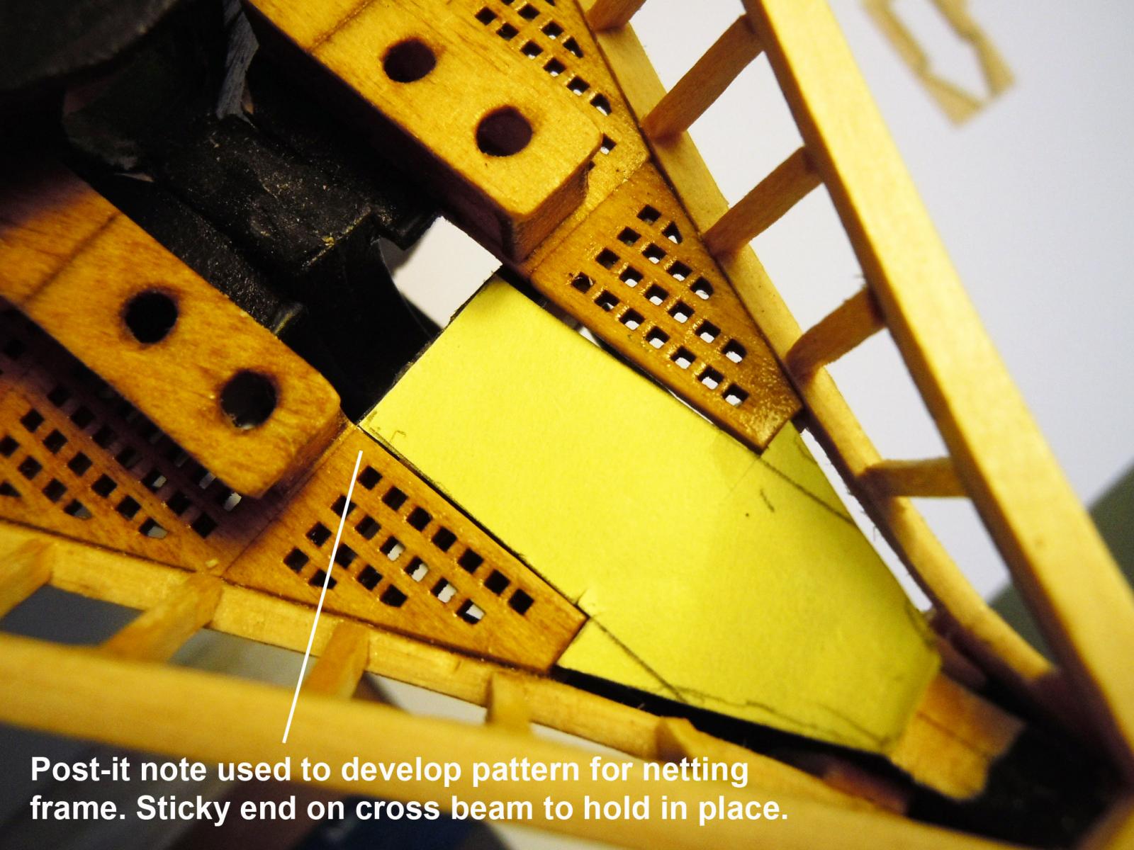
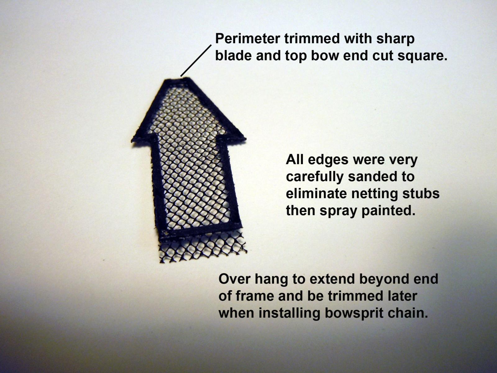
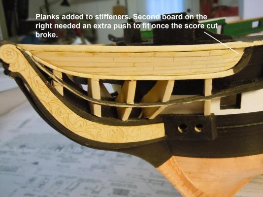
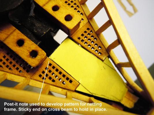
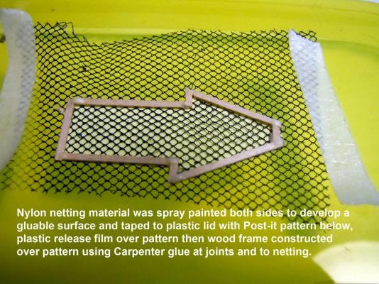
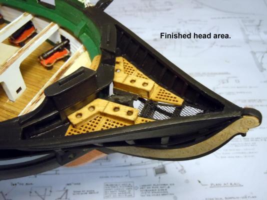
Once the stiffeners glue was set they were trimmed to 1/64" top and bottom on the outside to receive the head planks. I then used my old CAD system to develop patterns for planking. Next I created the pattern for the netting frame to carry the tiny nylon netting I had stashed away years ago for some future use. Nothing glues to nylon so the perimeter frame is a carrier to trap with Carpenter glue. Reached a milestone with the head area completed except for a couple of cleats I need to make and add to one of the stiffeners. Next to make cleats and do some testing on how to do the white trim.


-
Jon, thanks for the clarification, it looks like there were many reworks over the years. Also in the plan images above in one there are 8 stiffeners and another has 9. One drawing must be for revisions.
-
Jon, that was one of those forest versus tree issues; I was so focused on getting the curve and grating to match and just plain forgot to offset the grating and did not realize the errors of my way until the next day when setting the stiffeners. Of course I used an ample amount of CA and trying to fix it would just destroy the grates. A learning experience for others to benefit from; at least I was consistent. As for the bowsprit I have ample room right now and the question I am now trying to sort out is whether to used rope or chain. I consider myself still a novice at ship building and am learning everyday; but I am now wondering about the kit being dated as 1797 and being drawn with a fiddle head instead of a figurehead per the original ship. I think the fiddle head came about after someone chopped off Andrew Jackson's head in 1851. Hopefully some one can clarify this because I am starting to think that the plans are a combination of different period configurations.
-
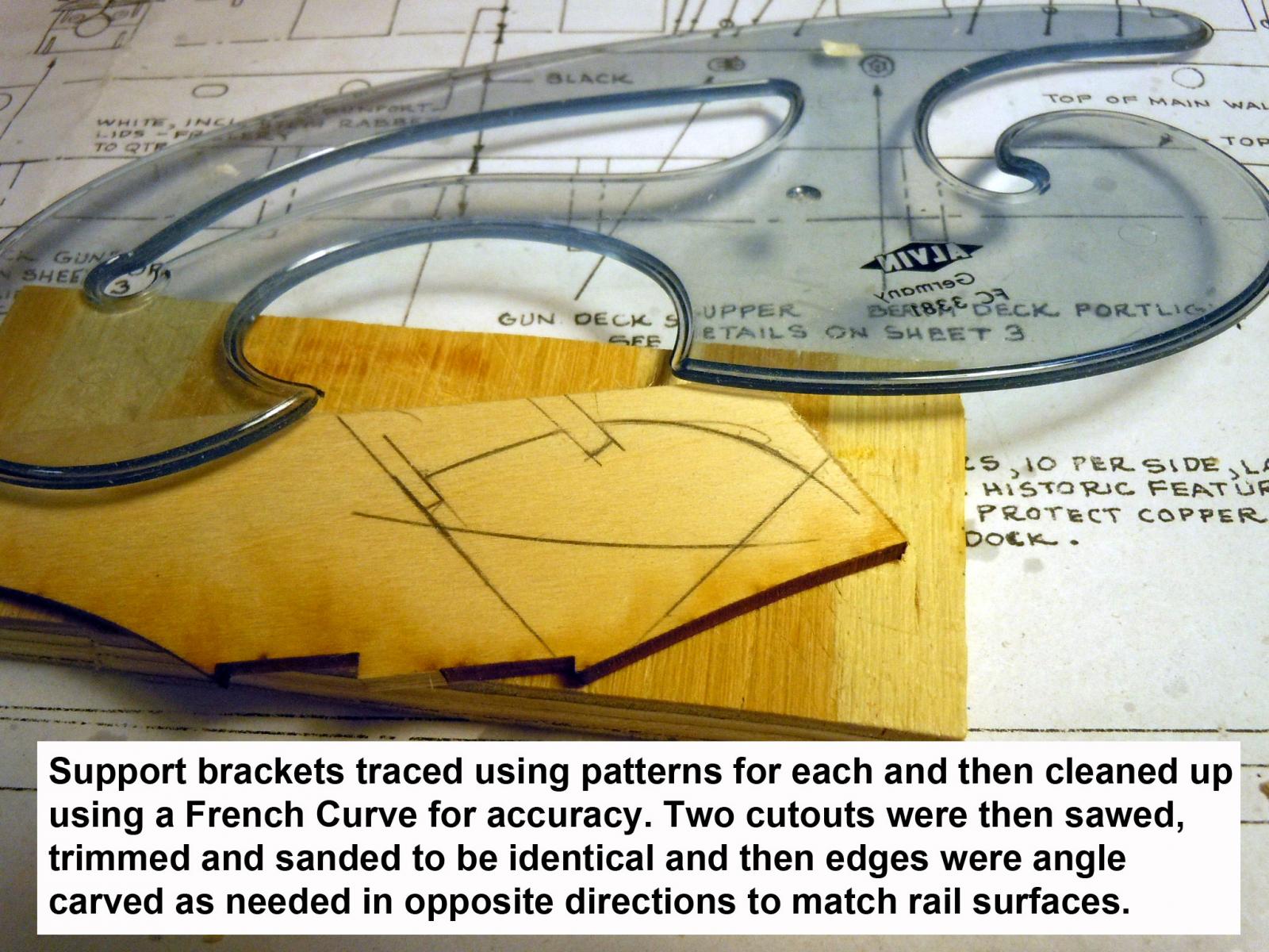
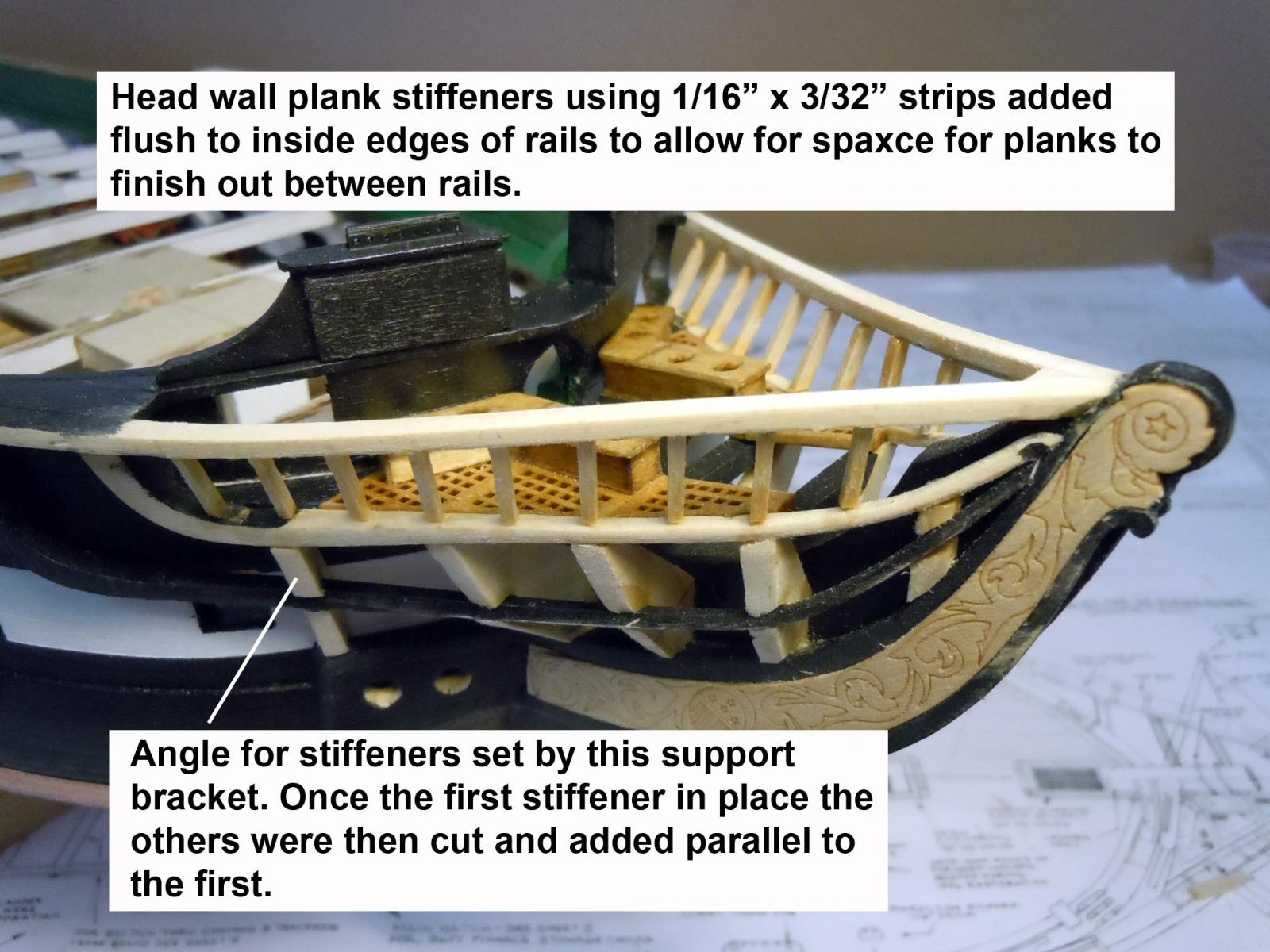
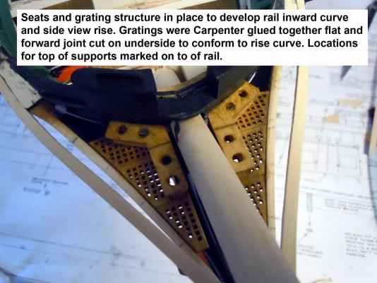
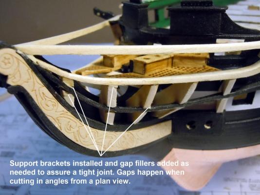
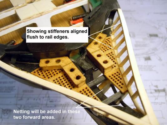
I finished up the head structures to be able to develop the curve for the rails and glued them in place. First I glued the gratings together using Carpenters glue glued the heads to the grating and when fitting the forward joint was cut and broke to match rail and then joint re-glued. Then using the support bracket patterns to make the sets of brackets needed. I used a French Curve for clean lines to saw to. Brackets were then added and fitted with gaps being filled. Gaps are unavoidable but are easily filled for strong joints. Note adjust the top locations of the support brackets to align with the joints in the grating which also set the location for the grating support beams. Once the support brackets are set the cross beams were added at the top of the brackets aligning with the joints of the grating. Note that the beams were painted black before gluing in place. Next came the plank stiffeners using 1/16" x 3/32" strips which required a bit of patience to cut and fit to each location. The angle of the stiffeners is established using the last support bracket and then the rest are added parallel to the first and flush to the inside edges of the rails. Next to decide whether to add netting and paint before adding the planking to the stiffeners.


-
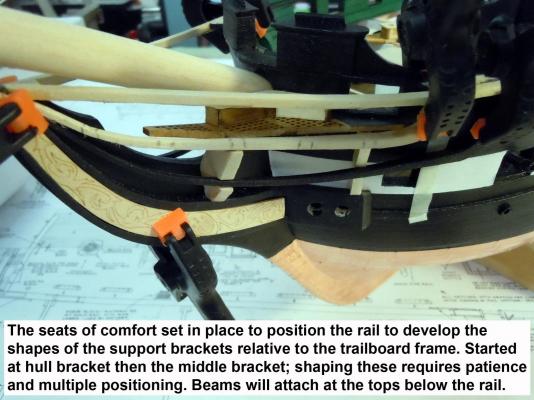
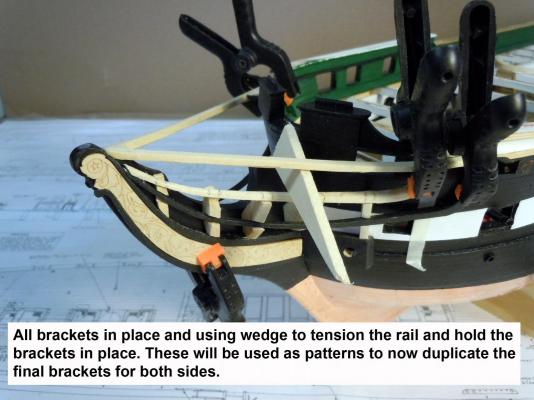
Just a quick update and thanks to Johnathan's help with plans I will have much better results than stumbling in the dark. These brackets are a challenge to develop with curves and angled surfaces. These are what I consider patterns that will be used to develop the final brackets for both sides. Building them required a great deal of patience with many trimmings and repositionings. I made the seats of comfort since they dictated the curve for the rail necessary for the the top of the bracket location. I will now make the final brackets and start gluing in place for final trimming. both bracket surfaces and rail surfaces appear to be flush with white trim strips added to them.
-
Matt, looks like you are off to a great start. To reduce ongoing breakage potential of those tabs I soaked them down to the joint line heavily with CA. The plywood in my kit was extremely dry and not the best grade for the job. Keep up the great work you are doing!
- 117 replies
-
- 7
-
-
- constitution
- model shipways
- (and 1 more)
-
Johnathan these prints are perfect! Thanks for your efforts for posting them. I can get everything I need from these. I am almost there with what I have done so far, but now the results will be even better. Thanks again!
-
Jonathan, Thanks!!!! Those are great pictures and really clear up a couple of issues on the grating I have been trying to sort out as well as the seats being level. Thanks again.
-
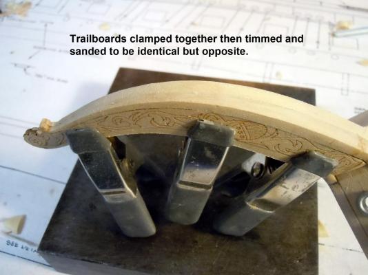
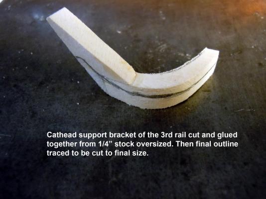
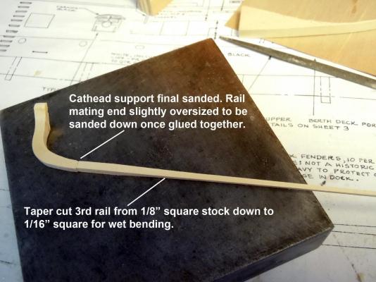
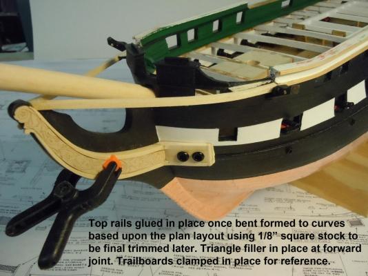
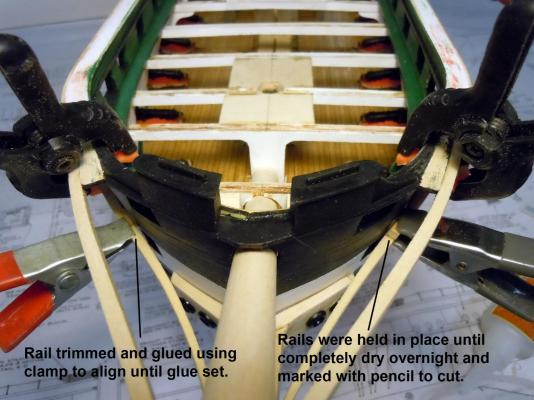
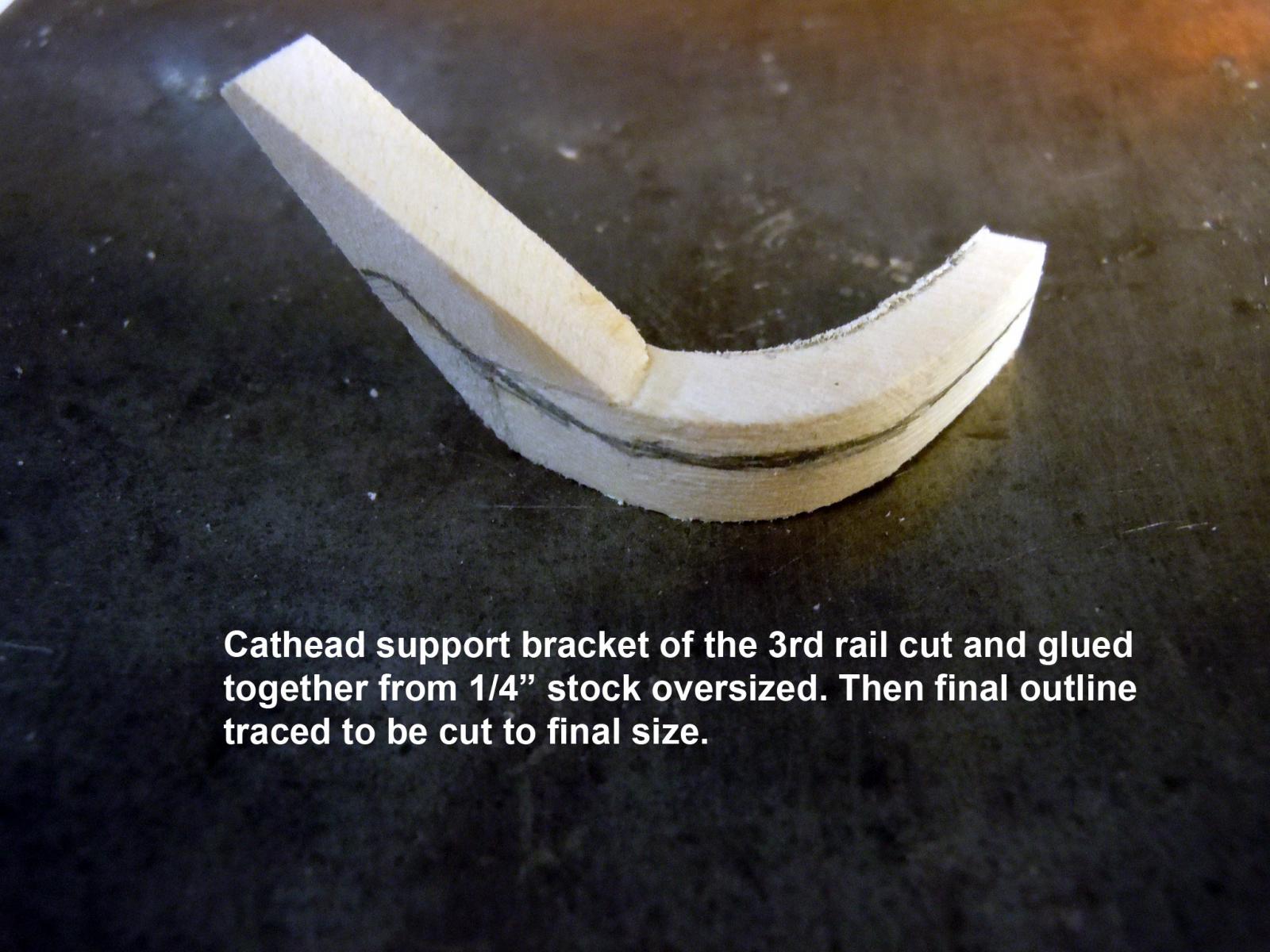
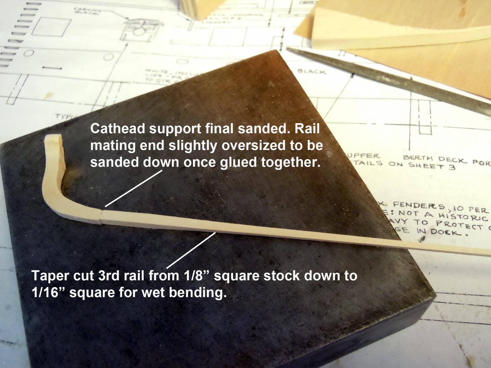
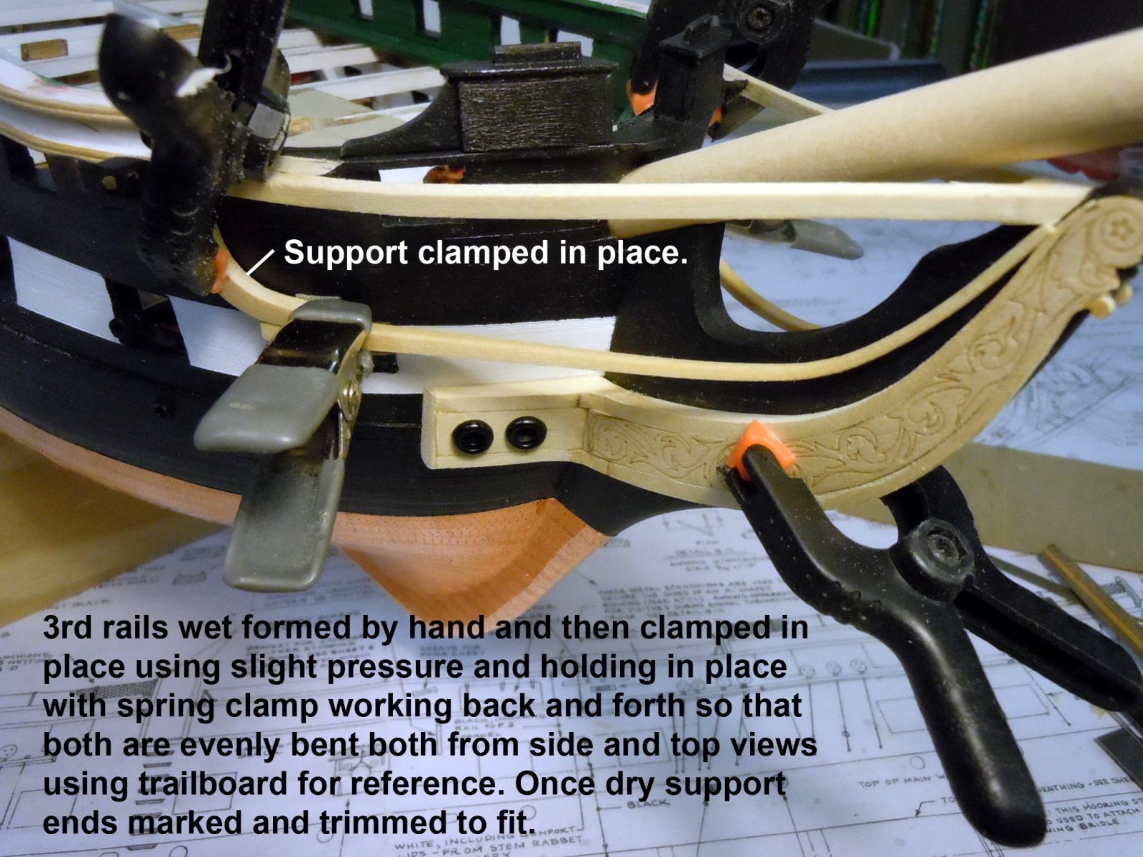
Built up both sides of the trailboard frames and then clamped them together and trimmed and sanded the perimeters to be identical port to starboard. This enables a consistent starting point for the rest of the rails to be built and is a benchmark for building. The trail boards press fit into place and are removable for painting later. Next I started with the 3rd rail that supports the cathead and curves to the billethead. First I built up and cut the two supports directly under the cathead that seats in part against the hull. Moving forward all parts will be made identical but opposite. Next I started with 1/8" square stock and tapered it down to 1/16" square that will be soaked in water and carefully hand formed to required curves using the trailboard frame for dimensional reference. This shows the wet top rails formed and clamped in place while waiting for the tapered rails to soak. These were able to be dry formed with the slight curves using the plans for reference. I am using 1/8" square stock that will be trimmed from the underside. I now have the top rail surface for reference as well as the trailboard frames. I am bouncing between the plans and photos of the real frigate for details. This shows the wet 3rd rails clamped in place and allowed to dry overnight to set to shape using tension between the clamped parts and the index into the rear of the billethead. Once dry the parts were marked and cut to length against the support; the right image shows the rail marked with pencil for cut line to butt to support. The left shows the glued joint of the support and rail being held in place with a clamp for alignment until glue set. Next I am trying to sort out the throne arrangements for the next rail so first I think I will fabricate the thrones and grating to help fiquire out the support brackets and beams. Having a hard time finding images of this bow area other than the one view in the instructions with no information. If anyone has images they can share it will be appreciated.