xken
-
Posts
841 -
Joined
-
Last visited
Content Type
Profiles
Forums
Gallery
Events
Everything posted by xken
-
 Thank you all for your book purchases! I hope you all enjoy and learn some advantages of working with brass as another model building medium. I to received the Anatomy of a Ship - USS Constitution which looks like it will be a great resource for doing the rigging when I get back to it.
 -
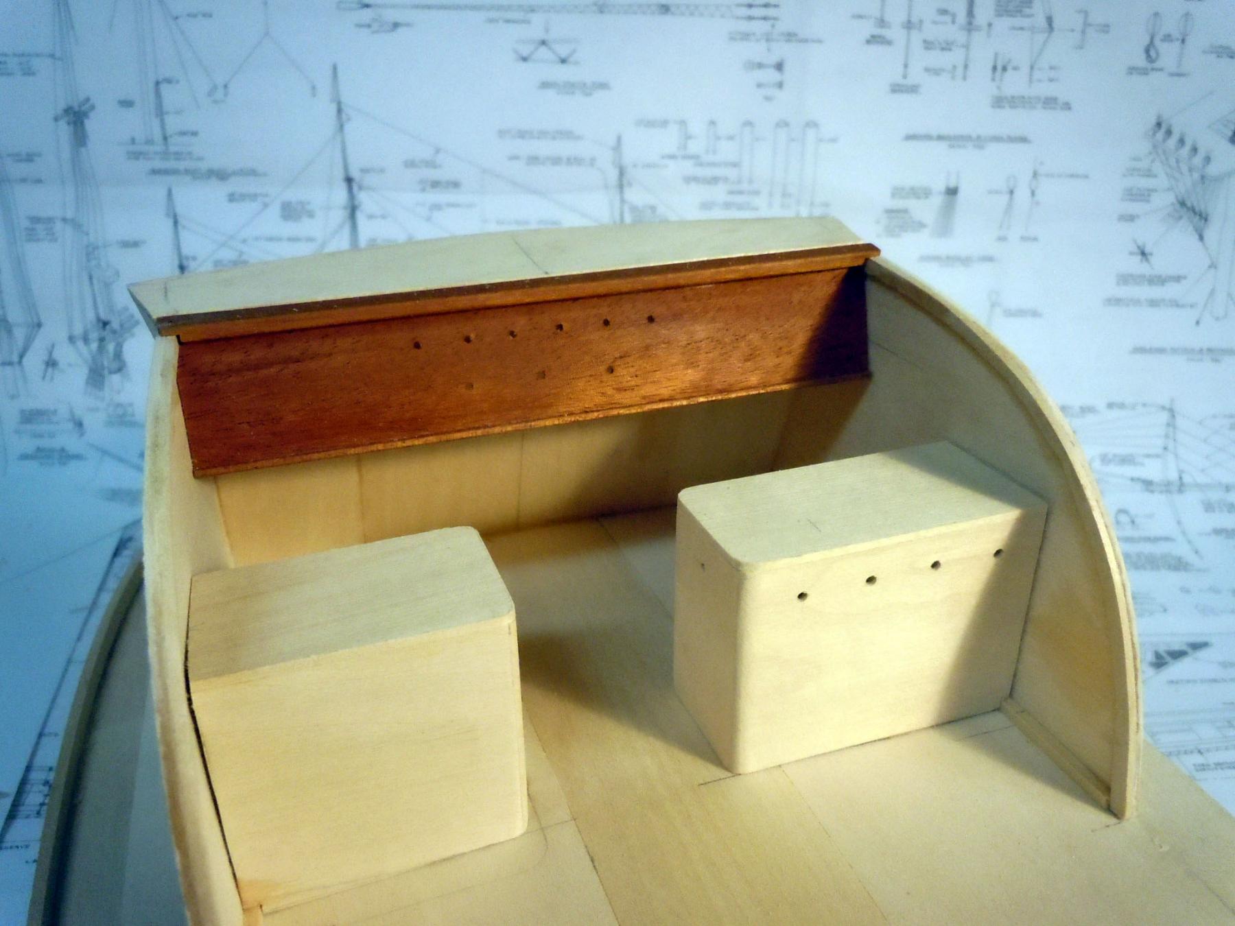
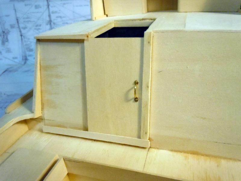
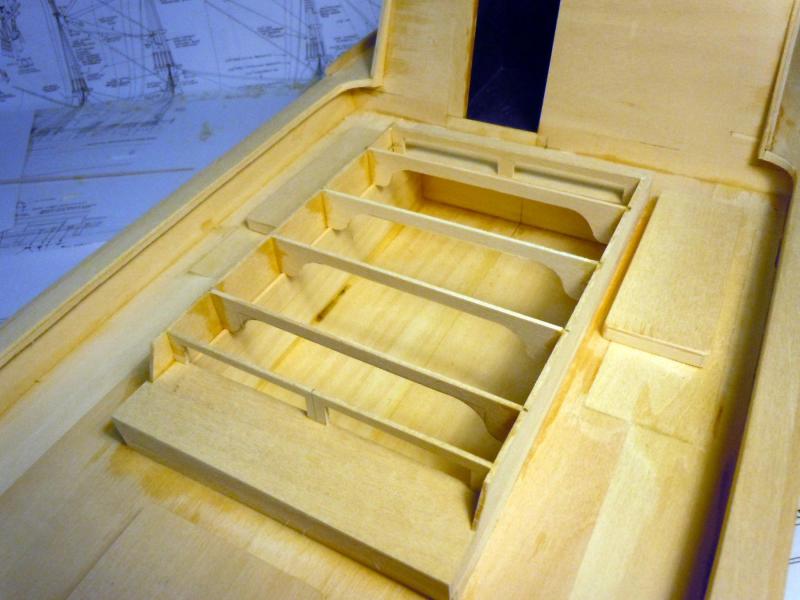
I decided to add the seat blocks as separate parts that can be removed to facilitate painting in the bridge area. After building them up I added indexing blocks on the deck for their locations once painting is completed. The starboard seat structure is also the battery box, hence the vent holes. I will add the 2" thick seat cushions later on down the road. I then reinforced the top horizontal surface of the bridge for the dashboard to align with. Notches were cut in the side wall braces to allow fitting of the dashboard against the side walls. The dash is indexed in and press fits into place. I located the centers of all the instruments and then clear coated the mahogany dash. I will turn the instrument bezels later using aluminum. I then cut the edges of 1/8" wood stock to form the tracks for the sliding hatch door. Originally I thought this hinged, but after studying the photos I realized I was wrong and that it was a sliding door. Once finished up the top and bottom rails were glued in place while the vertical stop is pinned to be removed for door to be put in place. I added the handle just for testing and can be removed to paint the door. Next I worked back and forth adding coaming and covers for the access panels and built up the framing for the the engine compartment that is hinged on the port side. Both the front and rear are open for air flow. The bracing was needed to carry the weight of people walking on them. All the work deck surfaces were coated with a non skid material/paint. Here are a couple of overall views. Next I will finish up the top hinged sliding door for the hatch that indexes with the sliding door. The slide rails are mahogany. I will need to find a source for small piano hinge for the hatch door. I assume that the first section lifts up and the second section slides back to open while maintaining a water resistant seal. Here is a picture of it showing the piano hinge. Merry Christmas to all!

- 162 replies
-
- 11
-

-
- dirty dozen
- fishing
- (and 2 more)
-
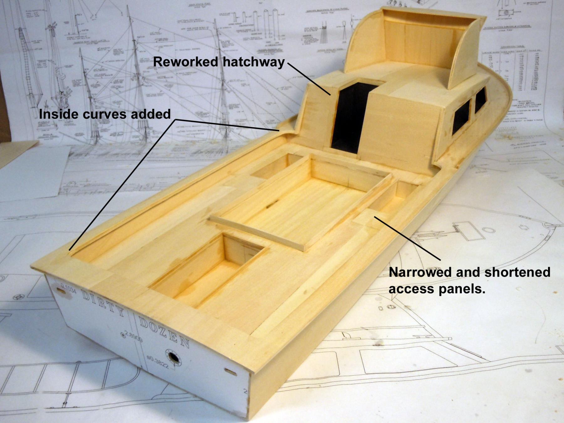
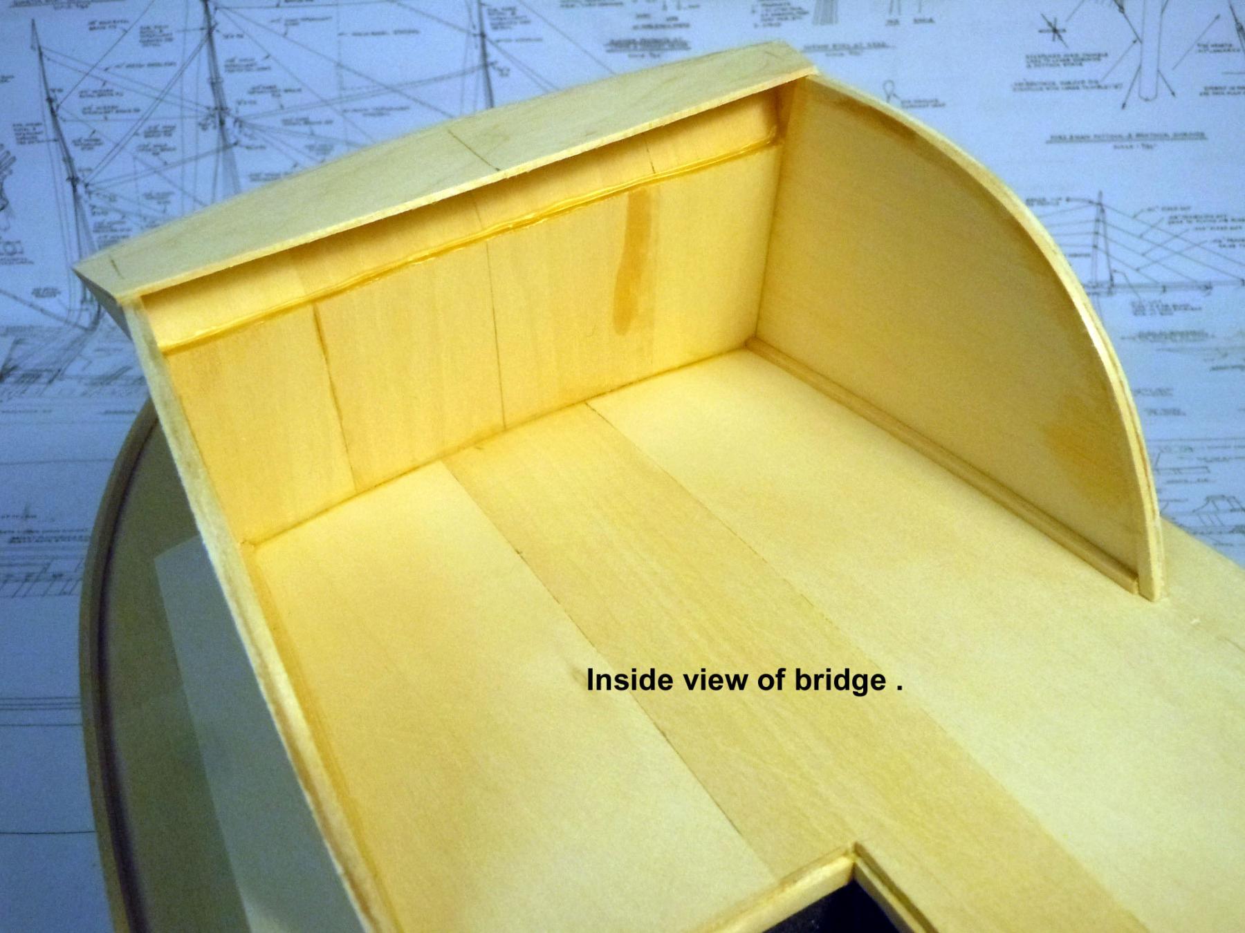
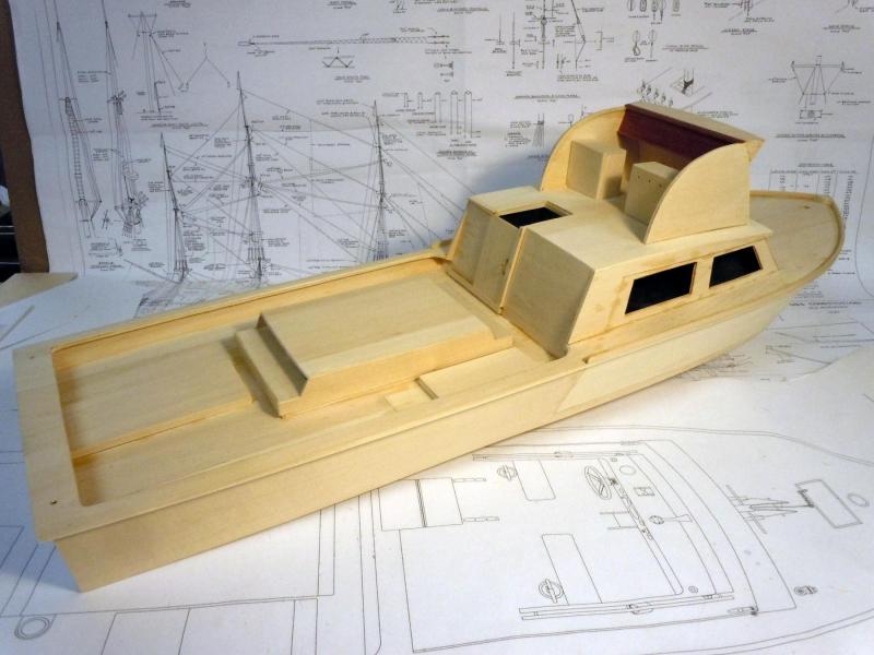
I added the cabin roof once dry and set then moved onto the bridge structure which required some edge mating to have both a clean exterior and interior. The challenge was matching the curves and bends. While waiting for glue to set on the bridge walls, I added inside curves to the work deck corners. I also spent time studying photographs and realized that I needed to narrow the hatchway door opening for the sliding door to work and that the two side access panels were too long and wide and reworked them as needed. Here is an inside view of the bridge work showing the inside clearance area at the top for the dashboard with gauges to come. Next to add the coaming, seats and compartment covers.


- 162 replies
-
- 14
-
-
- dirty dozen
- fishing
- (and 2 more)
-
Professor thank you for your encouraging words! No I will not neglect this build, but rope making in not overly exciting. I am making black standing lines between operations on the DD build. What kind of flying were you involved in? Last Saturday I ordered the Anatomy of a Ship- USS Constitution and hopefully Santa's elves will get it here before Christmas from the Constitution Museum store. Since my next step will be into rigging I am hoping it will be a valuable resource. In the meantime I am concentrating on the Dirty Dozen build for a Museum Board Update Presentation on Jan. 10.
-
Kurt, thanks I knew they must have had a name. I will be adding more to the other access panels as well.
- 162 replies
-
- 5
-
-
- dirty dozen
- fishing
- (and 2 more)
-
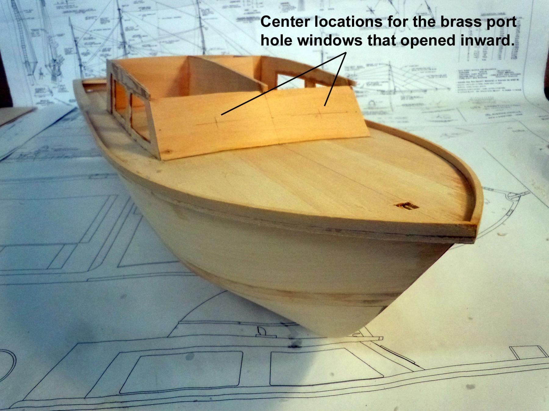
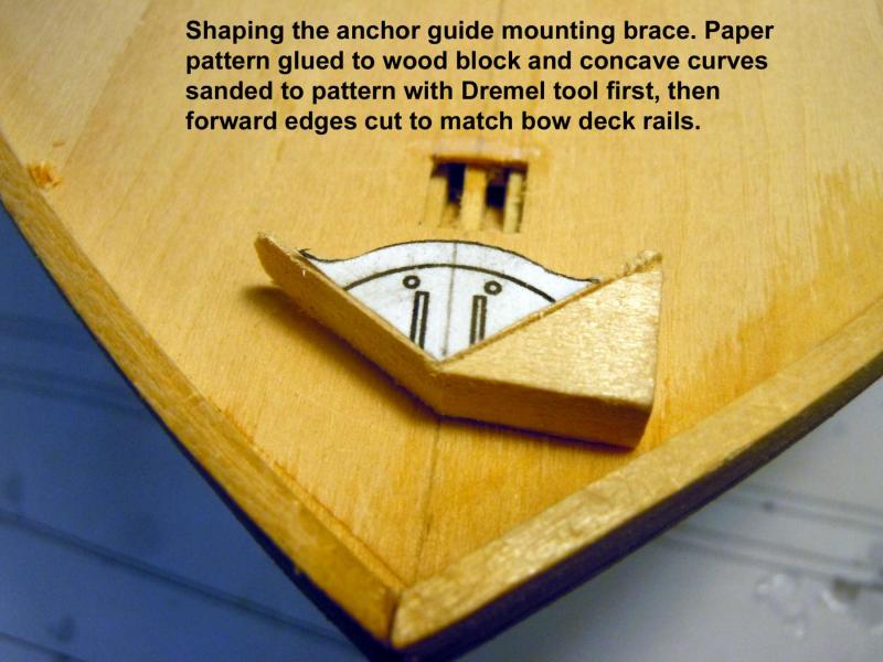
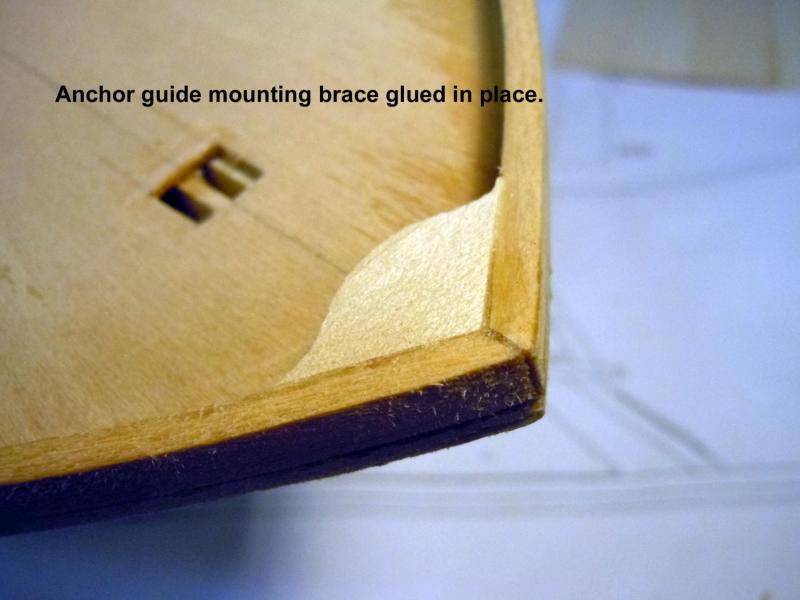
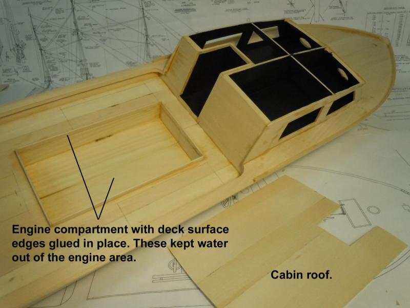
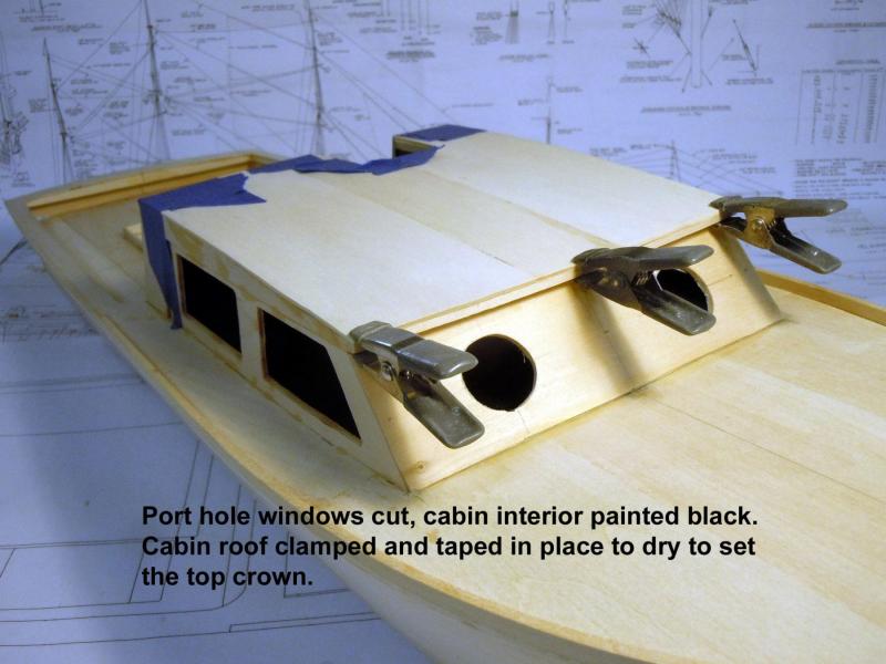
Ken, thank you! I had a Deja-Vu moment when working with the card stock back to about thirty years ago BC (before computers) I used these techniques while building RC airplanes for my son. The system still works well for me. I know if I built a 3D computer model in a program like SolidWorks I probably could print out a lay flat pattern; but with my computer skills I probably would still be at the computer building the 3D model. Yesterday I added the anchor guide mounting brace which on the real boat had concave curves blending into the deck rails. I finished up the cabin area by gluing pieces together for the roof. I also added a center lateral cross brace to defining the roof line and providing an additional glue surface for the roof since more structure will be added on top of the roof. Once all the fussing and blending was done I then painted the inside cabin surfaces black. This way rather than paint window surfaces black I can add more depth with clear windows. Painting these is much easier to do before the roof is glued in place. While waiting for paint to dry I cut out the large engine compartment and added the raised edges that prevented the water from flowing into the engine compartment. I am sure that there is a name for them. But I added then for increased strength before cutting out the smaller compartments. I also cut the round port hole window in the front cabin wall. Lastly, I added the wet roof to dry over night to the cabin to set the crown in it.
- 162 replies
-
- 12
-
-
- dirty dozen
- fishing
- (and 2 more)
-
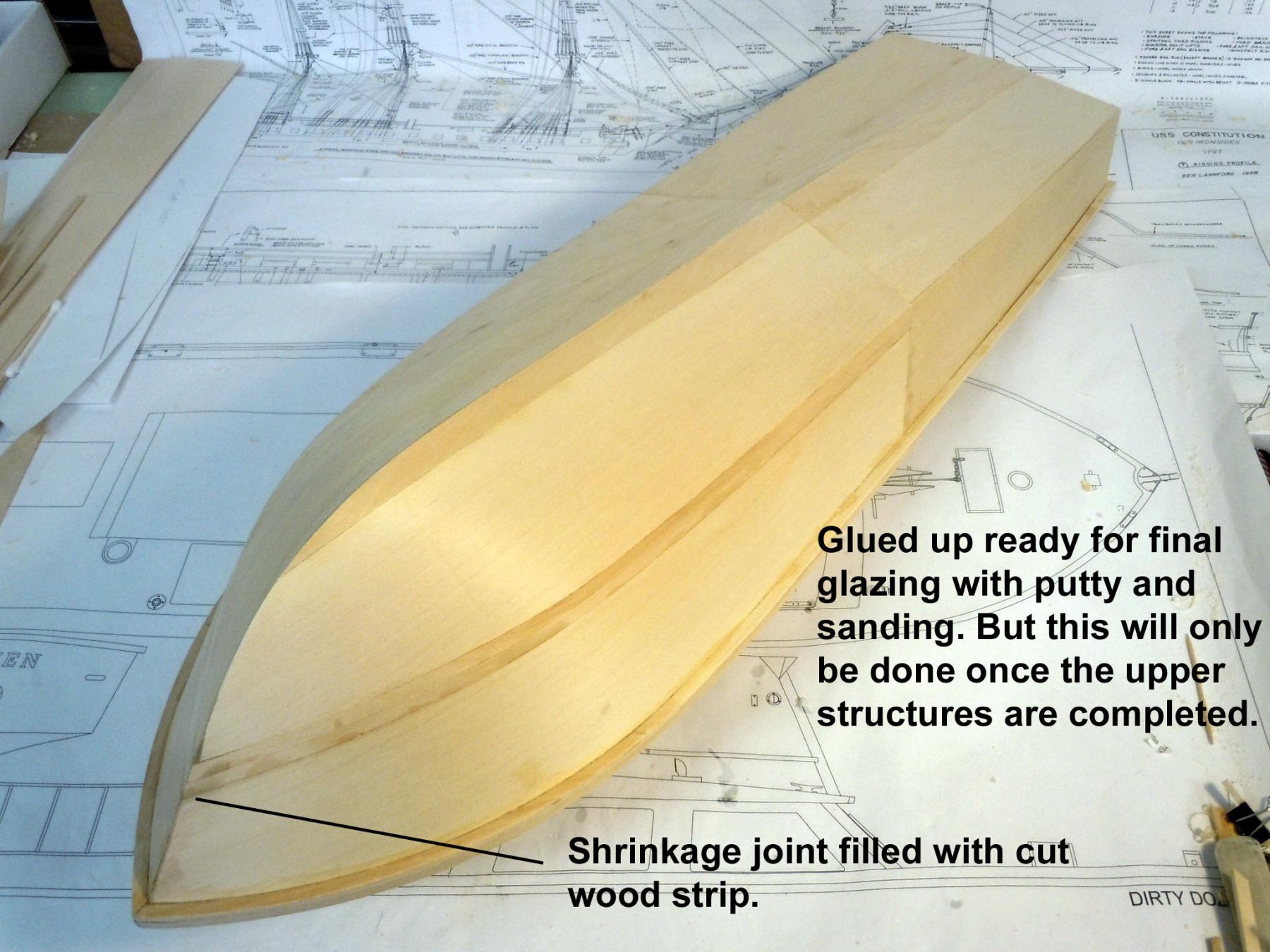
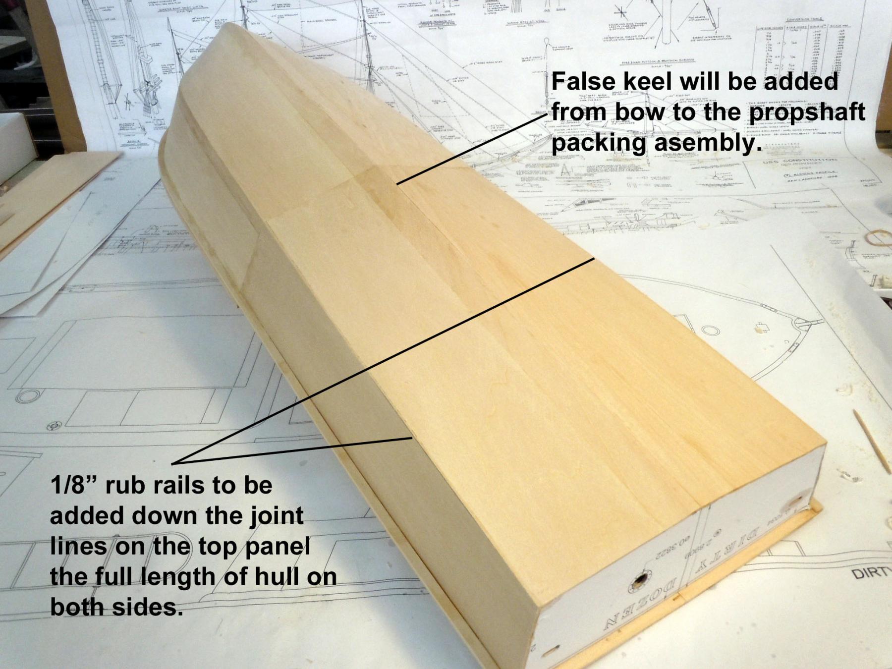
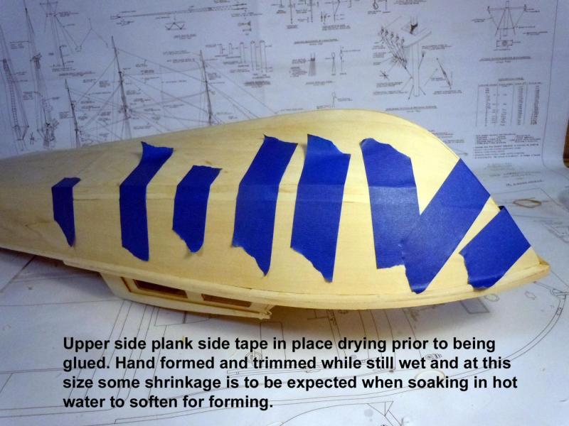
Steve, Brian thank you for your kind words. Brian I will be fine tuning the plans once complete and I know that the museum plans to sell some form of them as a fund raiser for the museum. The full size plans are CAD size D 34" x 22". As for the price of the plans I have no idea at this point. In fact you may be able to help the museum...what would you be willing to pay for a set of plans? Finished closing up the hull last evening after soaking and hand forming and trimming the edges for a tight fit. I knew going in that hot water would expand the wood a bit especially at this size and that it would vary based upon the individual sheet of wood. Both sheets had tight fits when wet and a 3/64" gap developed at the bow once completely dry. Not a big problem, just cut a wedge sliver and filled the gap. There will be a false keel and rub rails to be added down the road. For now the hull will be allowed to set and I will move on the the upper deck structures and once all the structures are complete I can get back to glazing putty and finish sanding the hull. This shows the cut side taped in place and drying. Here are a couple of overall views. Now back to the upper deck and I located the holes for the two forward cabin wall port hole windows. I will add the eyebrow for more structure before cutting out the windows.


- 162 replies
-
- 9
-
-
- dirty dozen
- fishing
- (and 2 more)
-
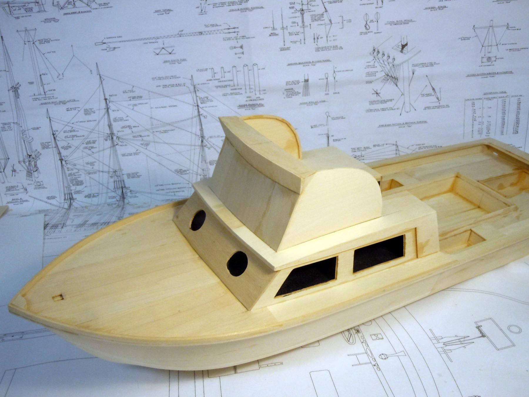
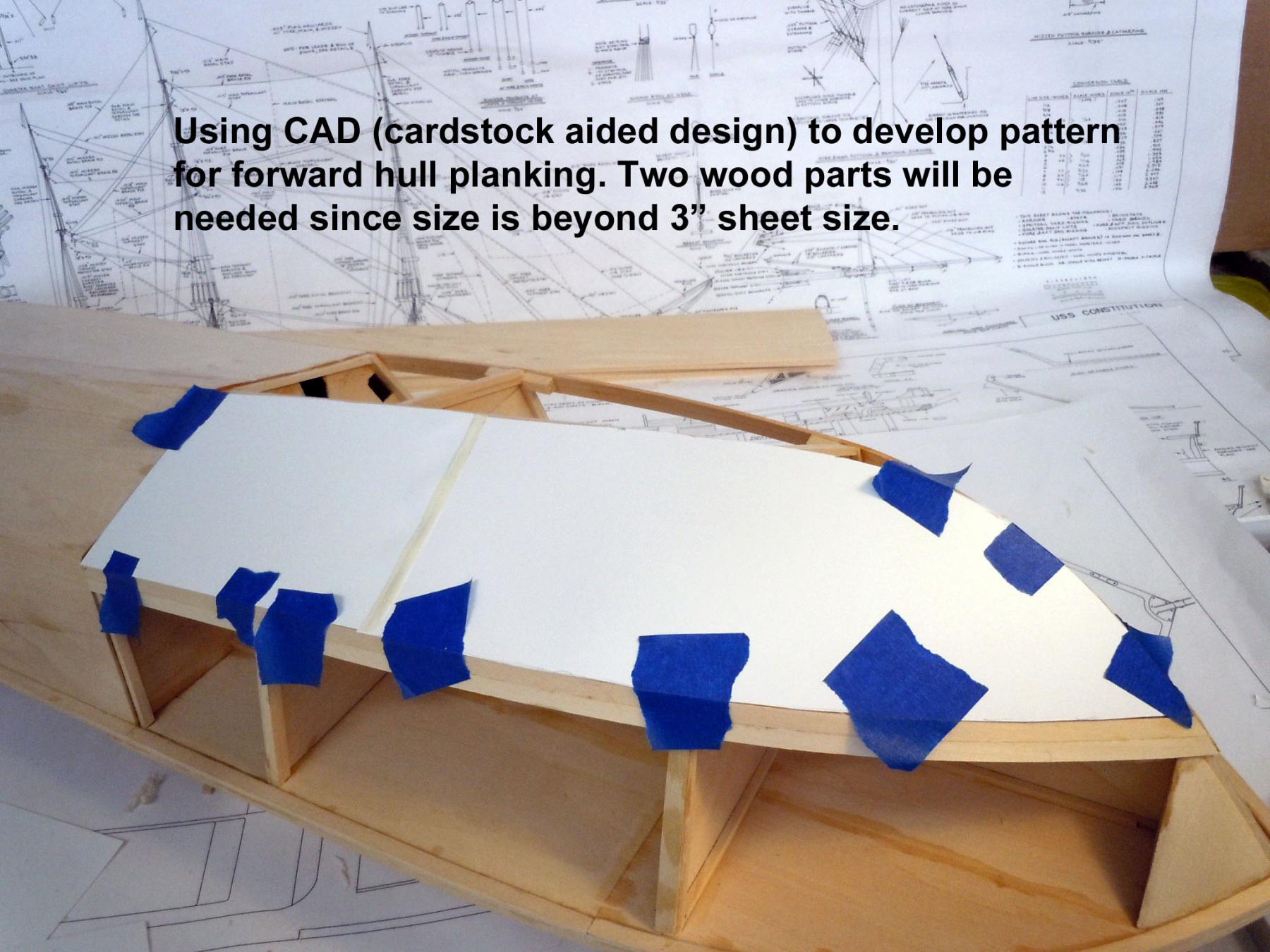
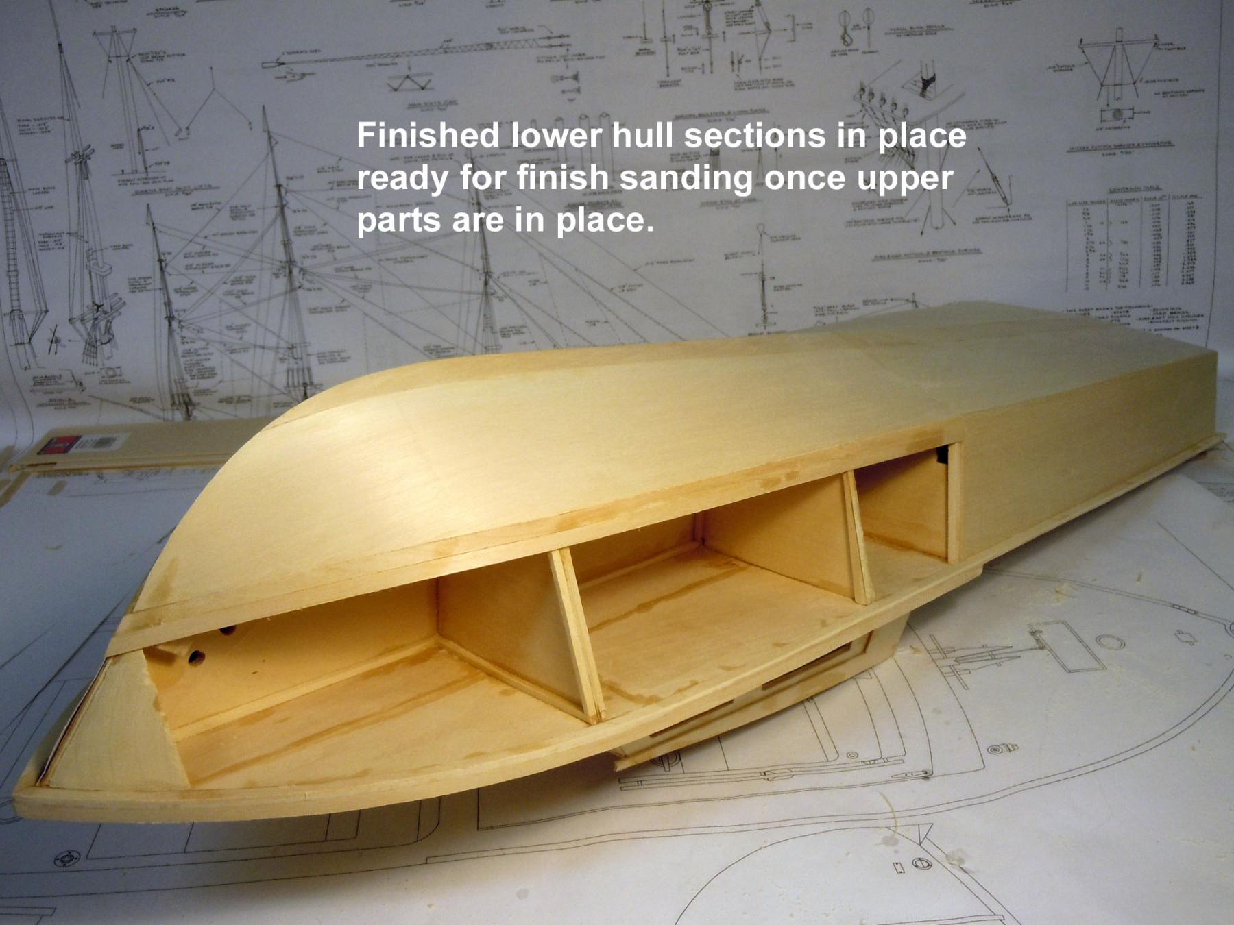
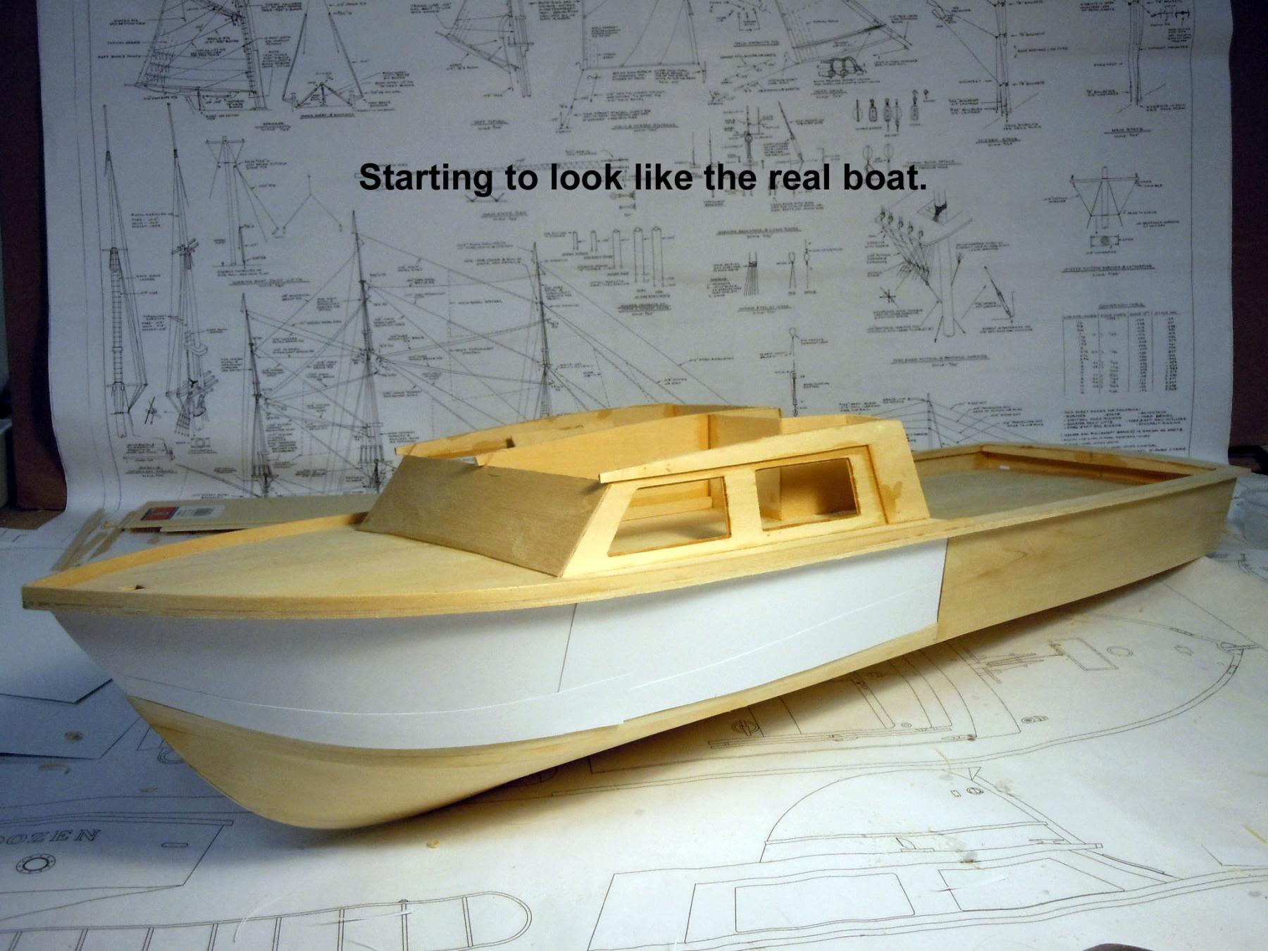
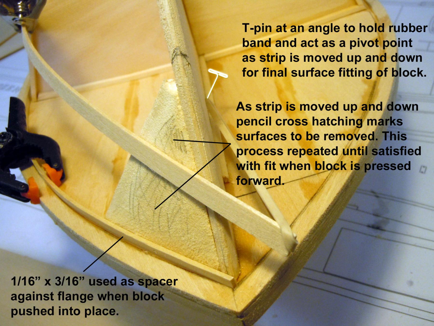
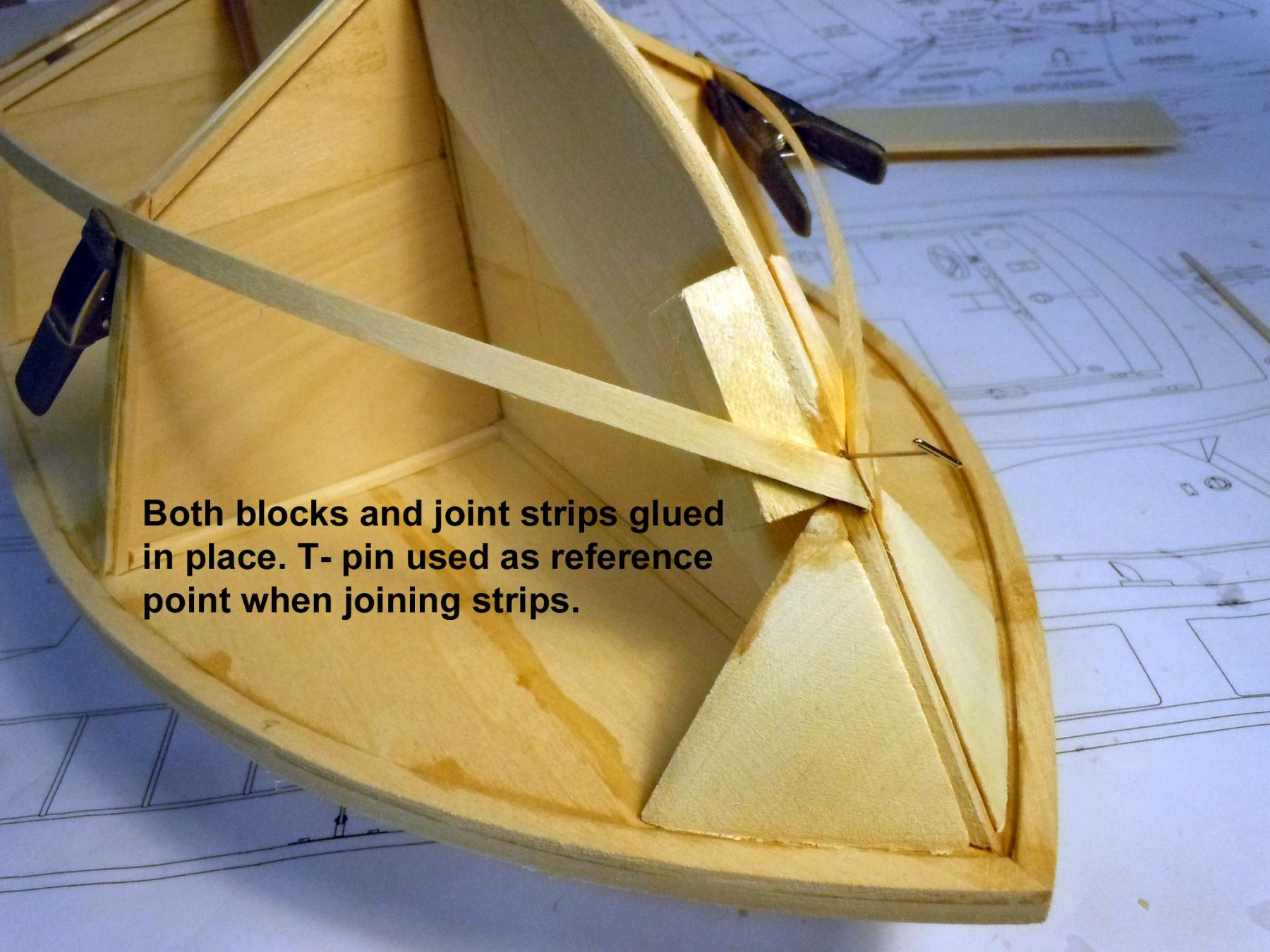
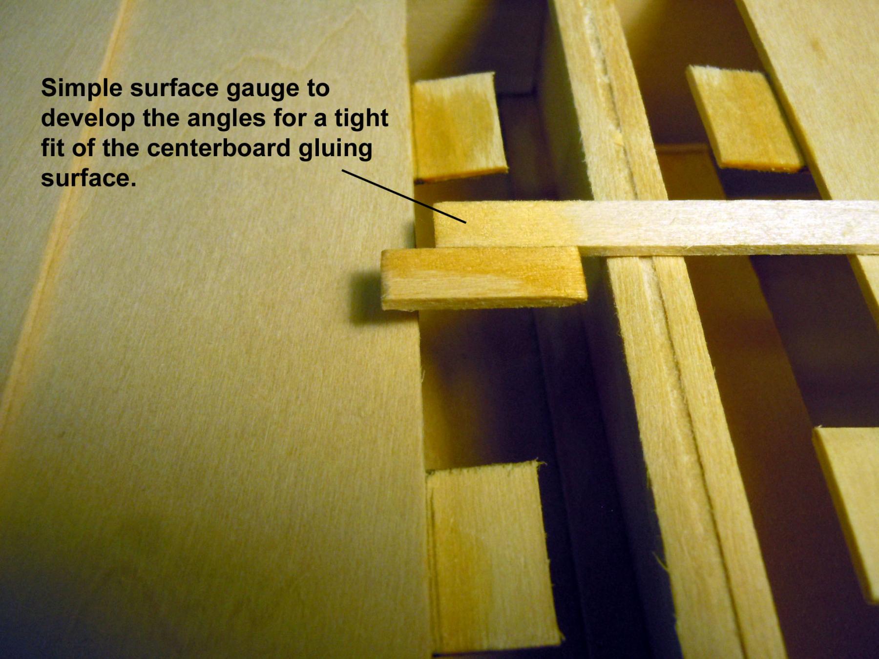
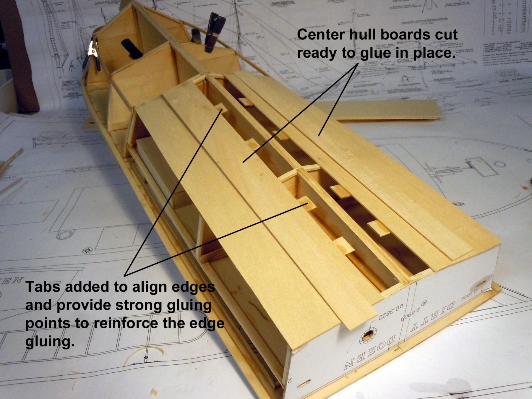
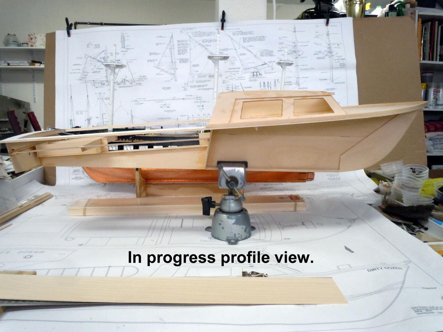
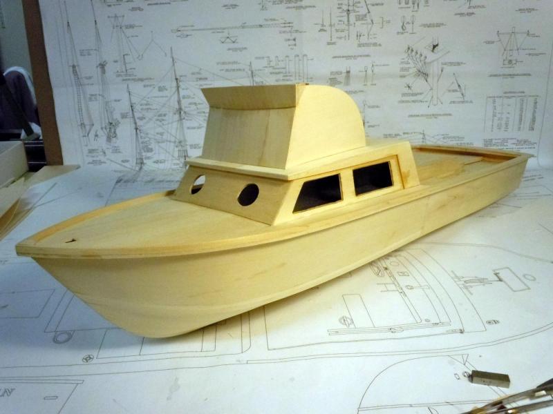
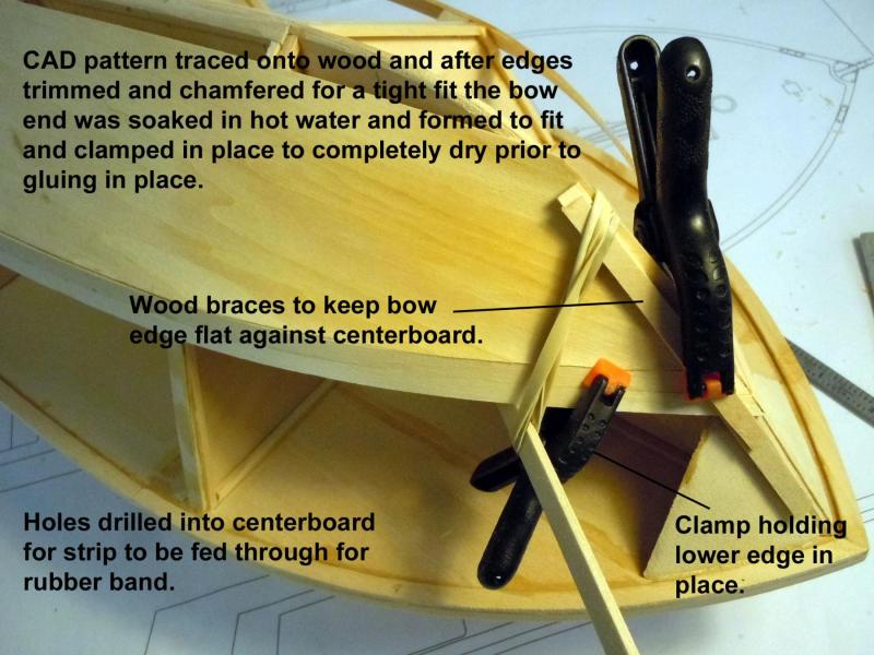
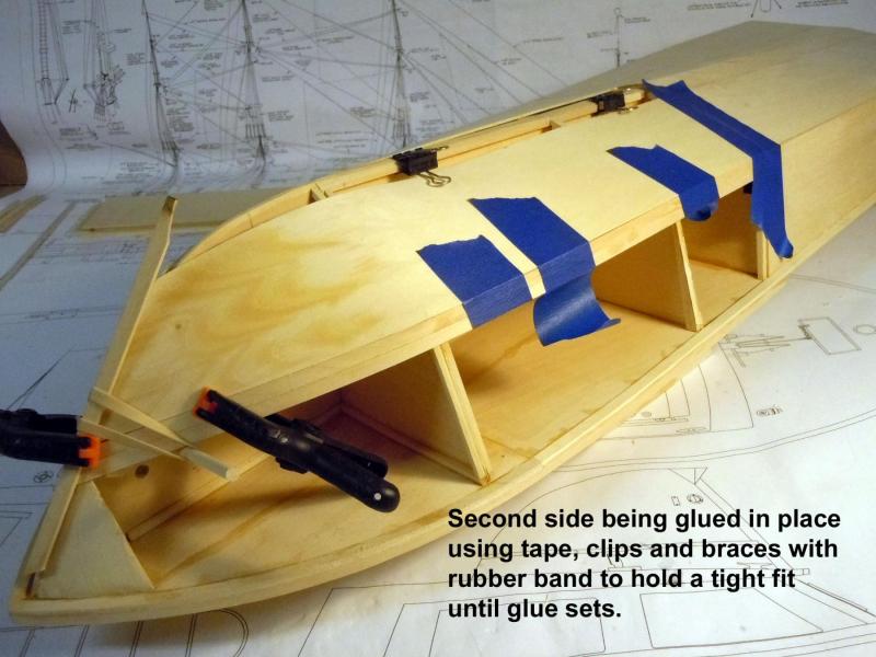
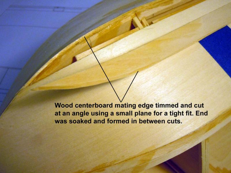
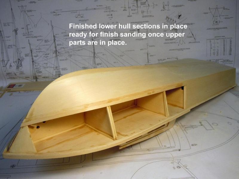
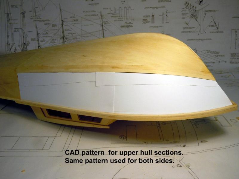
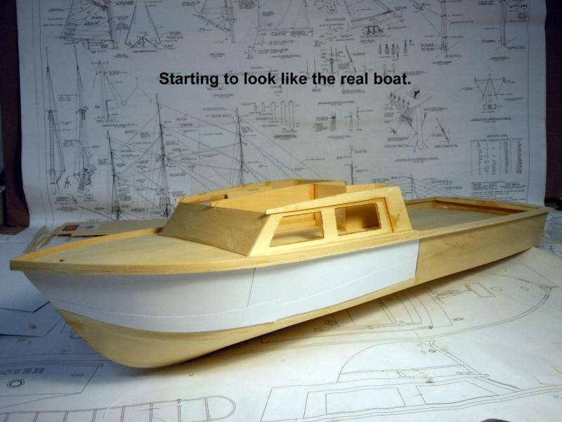
I fell back on my vintage CAD system to develop the planking for the forward hull using Cardstock Aided Design. Time spent to cut carefully with multiple pieces as needed and this one pattern can be used for both sides. Here you can see the pattern taped in place. The 3" width of the Basswood sheets I have will require using two parts. Once the first wood part is cut the top straight line is traced on the CAD pattern for the second piece. The wood pattern was cut and trimmed with a small plane to angle cut the curved lower edge and forward bow portion. The bow end was set in hot water to soak and formed into place with edges being trimmed as needed for a tight fit and the piece allowed to dry enough to glue in place. Holes were drilled in the centerboard to insert a dowel to hold a rubber band with a braces to keep the bow edge in place. yellow glue was applied to all edges and gluing surfaces. Here is the other side being glued in place with forward rubber band clamping and tape to hold edges tight. Spring clamps were positioned to hold the top edges just snug to the bulkheads. Some finger pressing was needed to adjust the lower edges until the yellow glue tacked off due to slight stretching of the tape. Here the top filler parts were cut using the CAD pattern; curved edge trimmed with plane and soaked in hot water to form. Here you can see the chamfered edge while the lower mating edge is the finished straight edge. Tape and tacking with CA were used to hold in place while yellow glue set. Note that gluing tabs were added to the upper edge of the lower hull part. Here are the lower hull sections in place and ready for finish sanding once the upper parts are installed. Here I am back with the CAD system developing the pattern for the upper hull. Note that a second 3/16" strip was added to make up the difference for the 3" sheet width. Here it is starting to look like a boat. The lines reminded me of it looking like a small P.T. boat.

- 162 replies
-
- 11
-
-
- dirty dozen
- fishing
- (and 2 more)
-
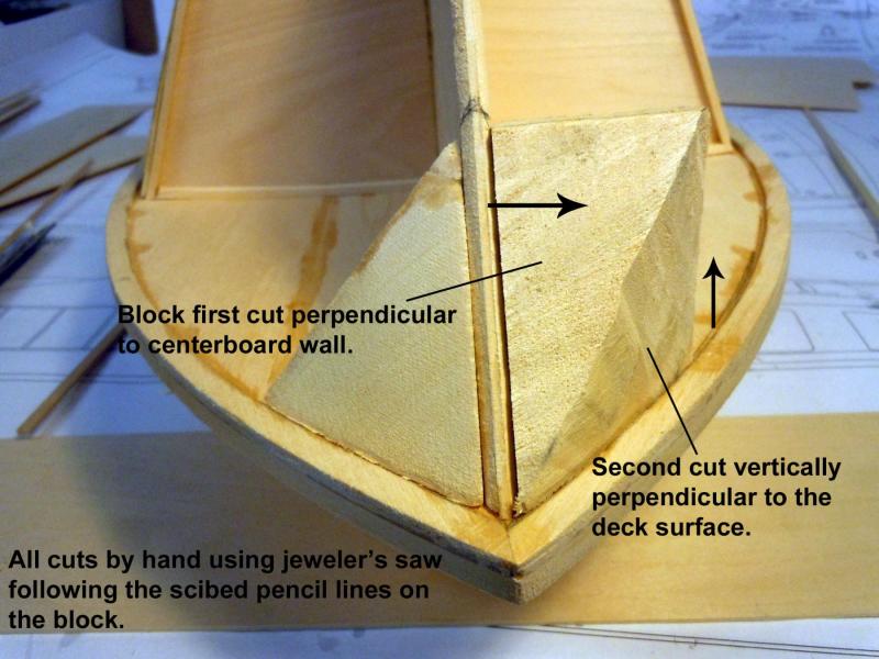
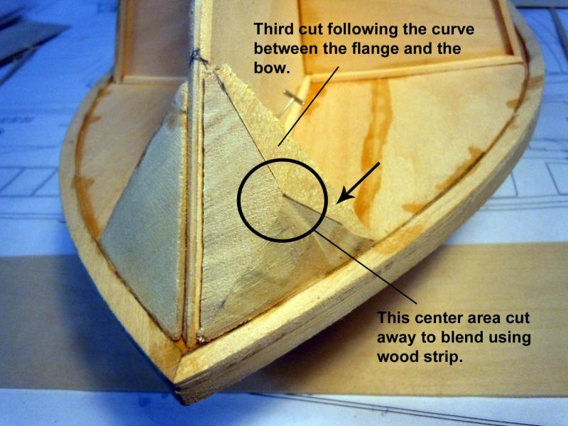
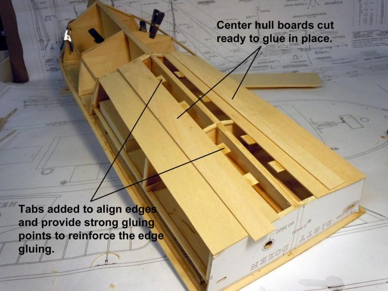
Patrick, yes I like being good friends with Mr. Geometry, he has saved my butt more than once. I had a good productive day yesterday and made good progress on the hull. I have added notes in the pictures that should explain what is happening. I have discovered that the hull planking will require some strip planks because of the 3" width of the sheets I have. Now back to the forward hull.


- 162 replies
-
- 13
-
-
- dirty dozen
- fishing
- (and 2 more)
-
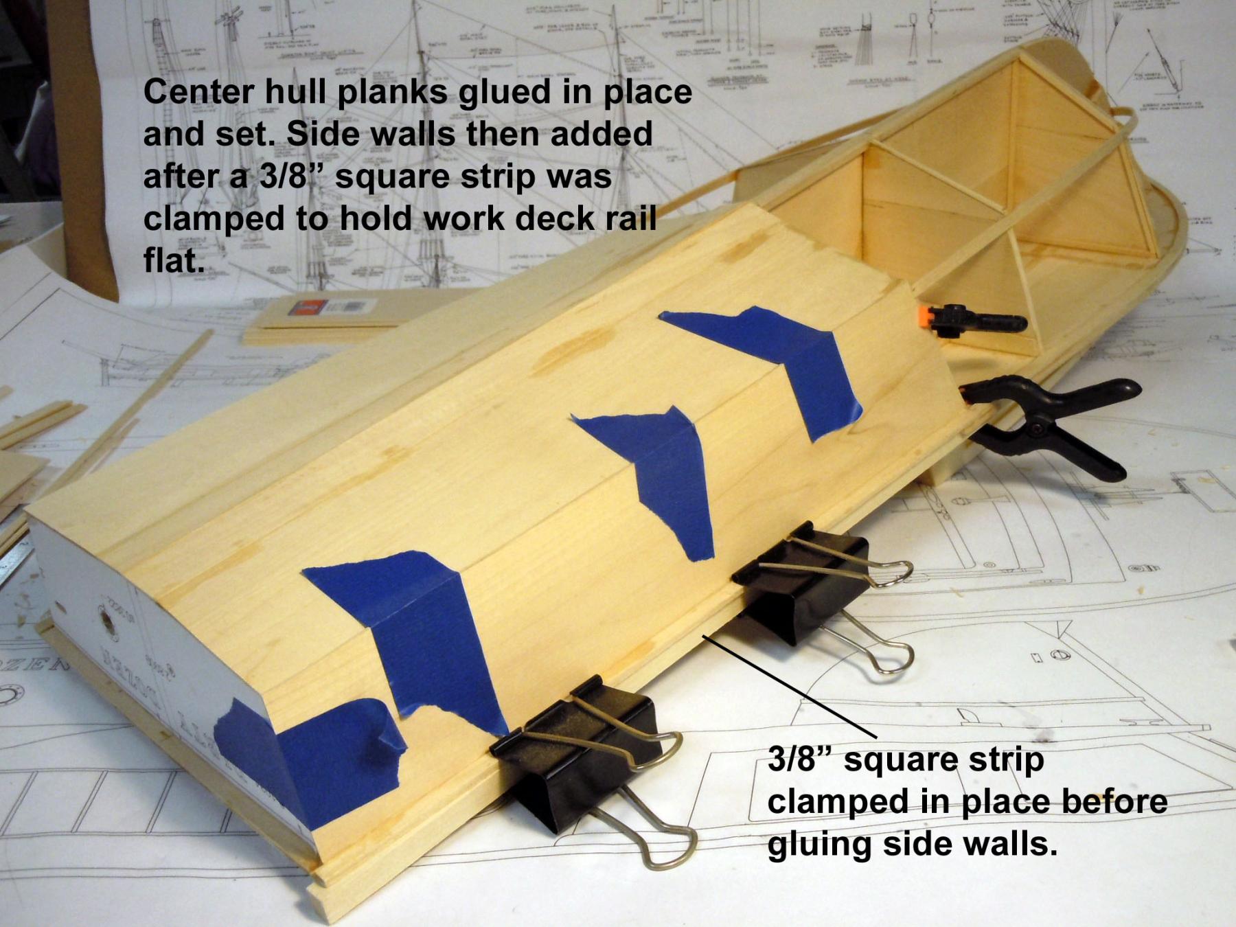
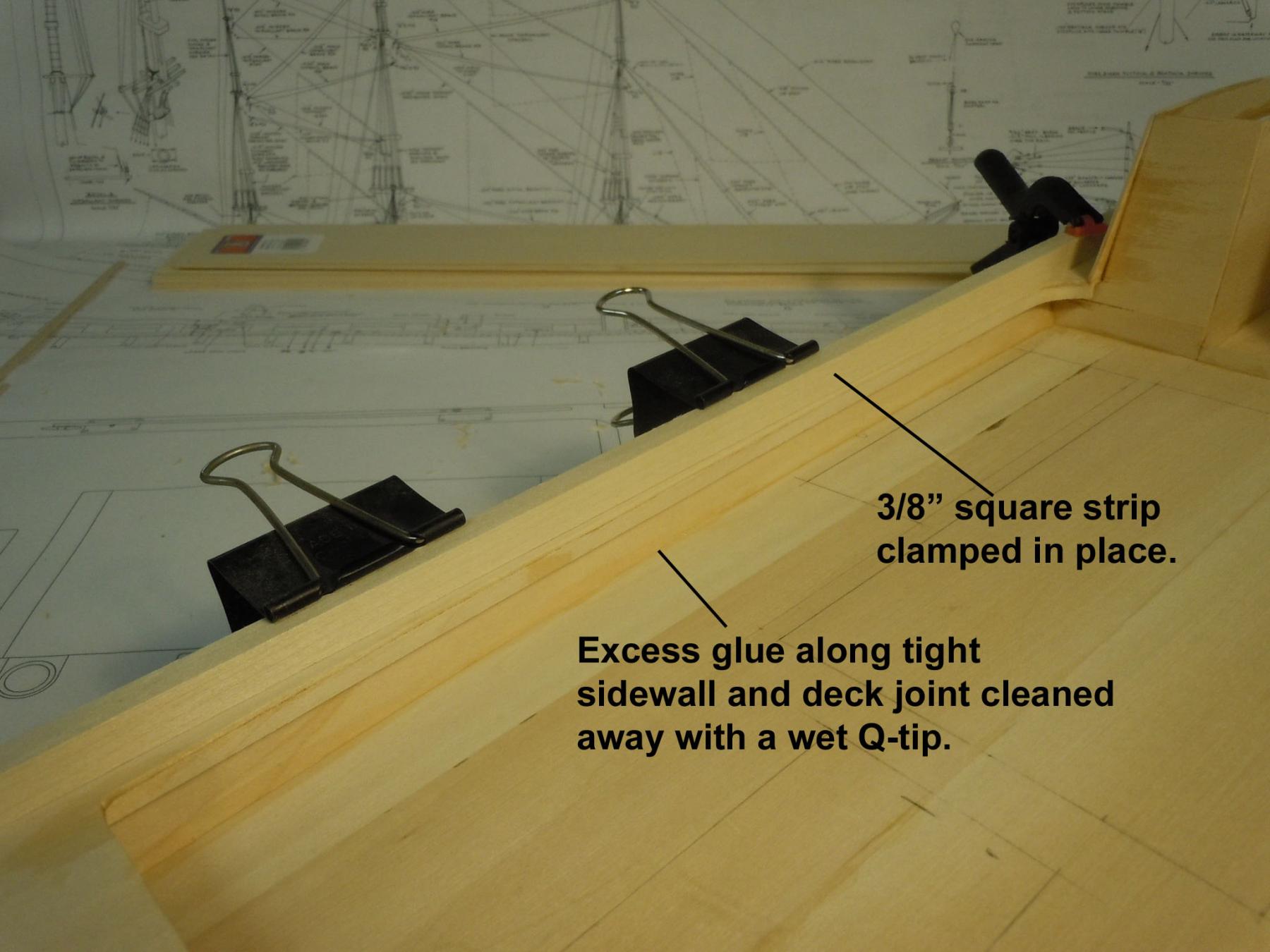
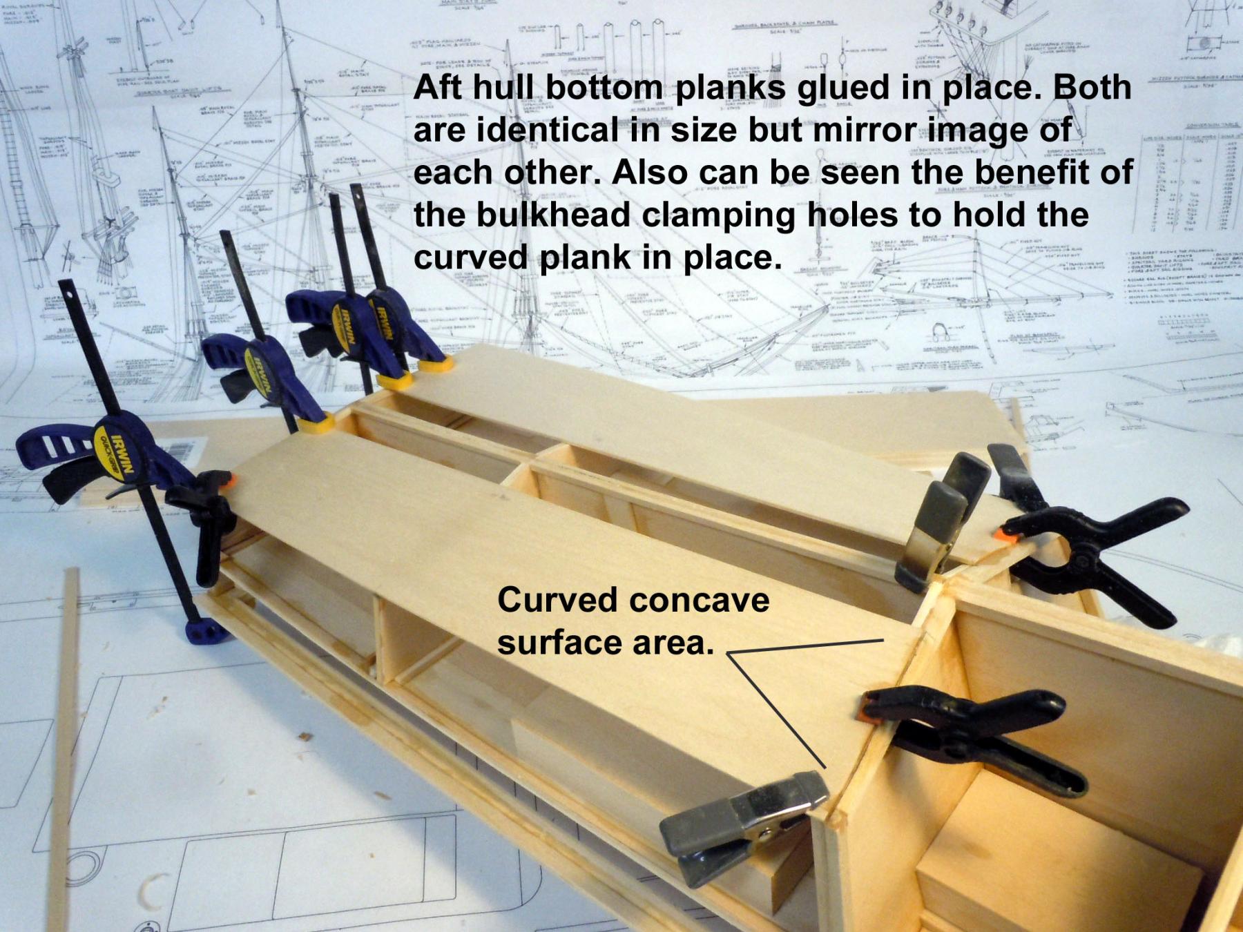
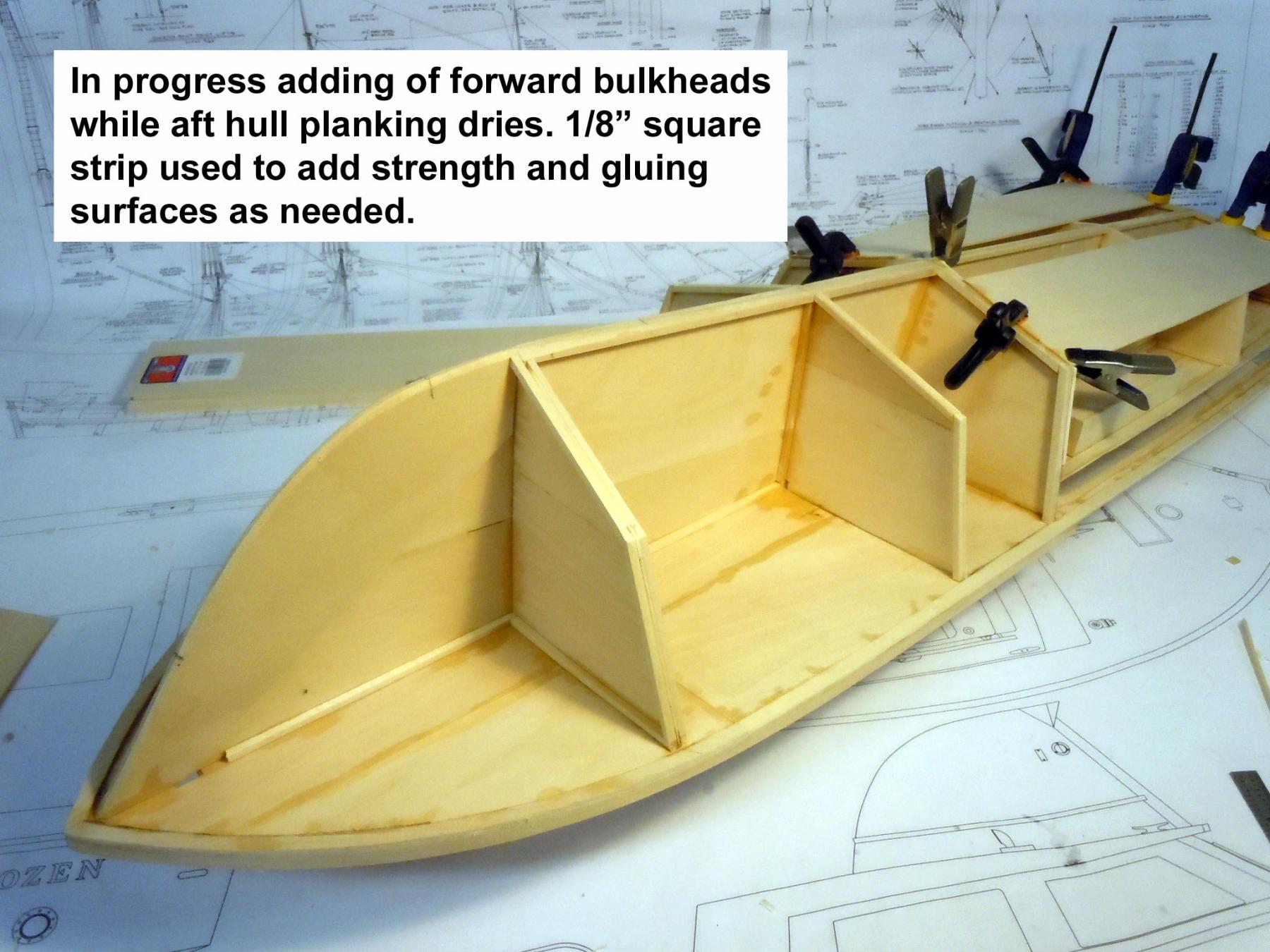
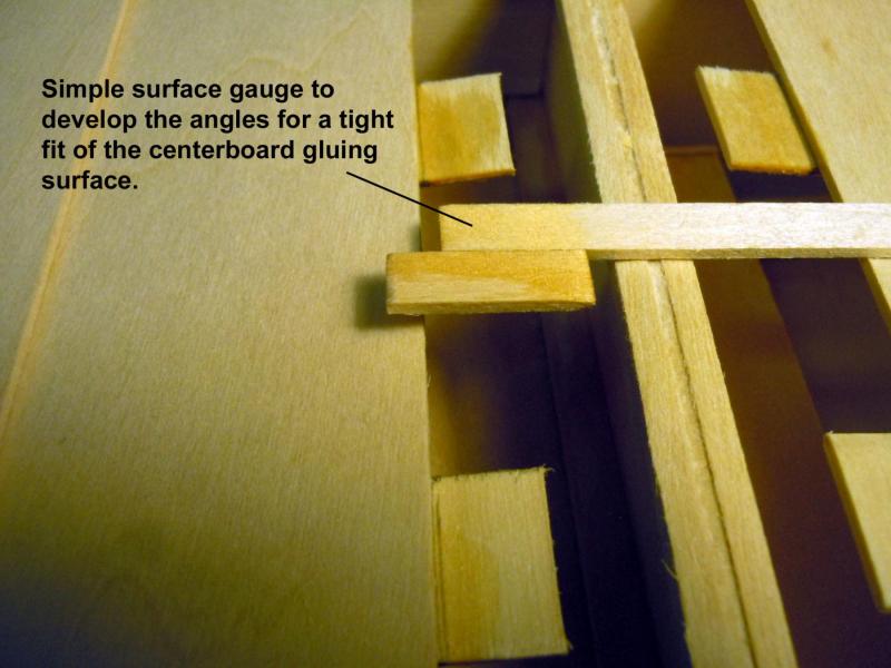
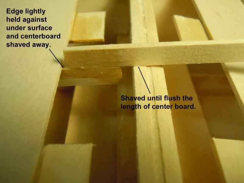
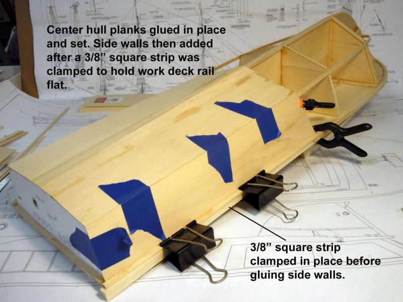
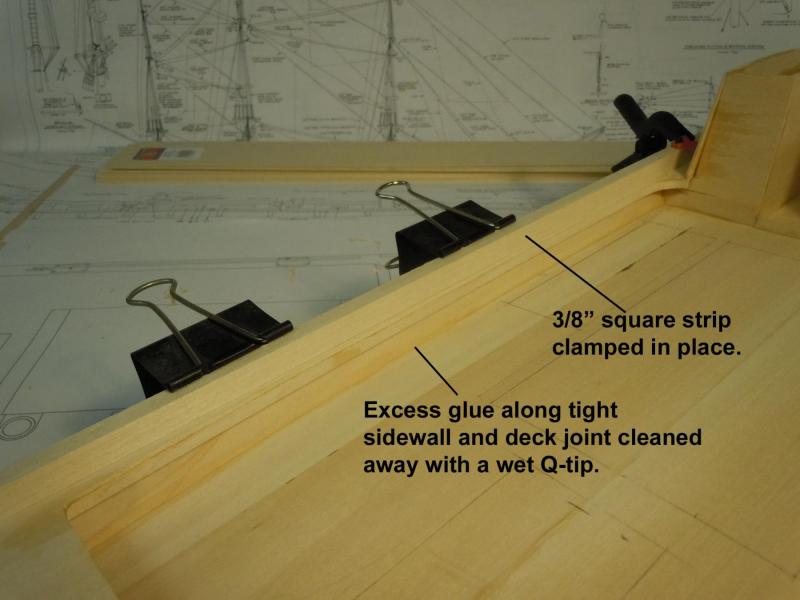
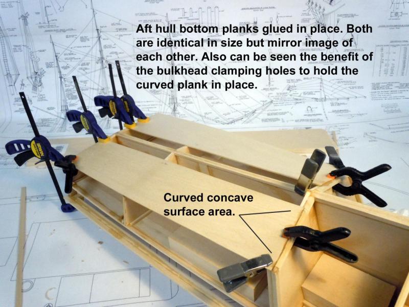
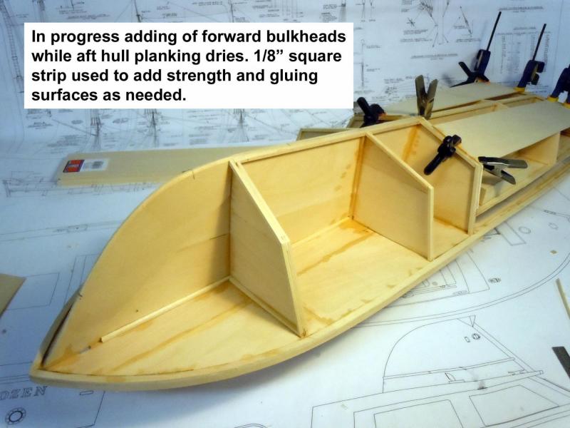
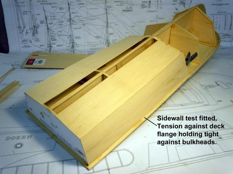
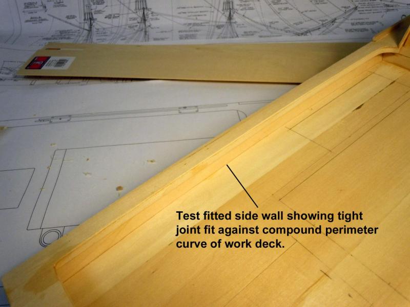
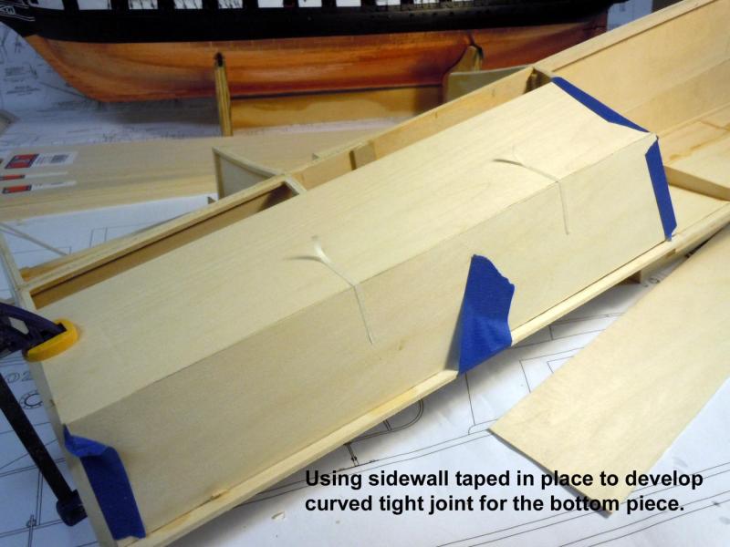
As I worked back and forth on the forward bulkheads I decided to add the aft hull planking using 1/16" x 3" Basswood sheet. I cut two identical pieces but mirror imaged for port and starboard sides. Here they are glued in place and note the advantage of using the clamp holes cut into the bulkhead to hold the concave curve of the hull. Here is an "in progress" of developing the forward bulkheads making both left and rights and reinforcing them with 1/8" square strip stock which will also add a good gluing surface as well. I have decided at this point to add a solid nose at the bow to define the junction point of the wale joint of the hull. Later a wood strip will be added at this joint line. While waiting for the bulkheads glue to set I decided to test fit the hull sidewall to check my joint fit between the work deck and sidewall. I was very glad of the results. My friend Mr. Geometry came through for me again! Now back to the forward bulkheads and the center boards for the aft hull bottom.
- 162 replies
-
- 10
-
-
- dirty dozen
- fishing
- (and 2 more)
-
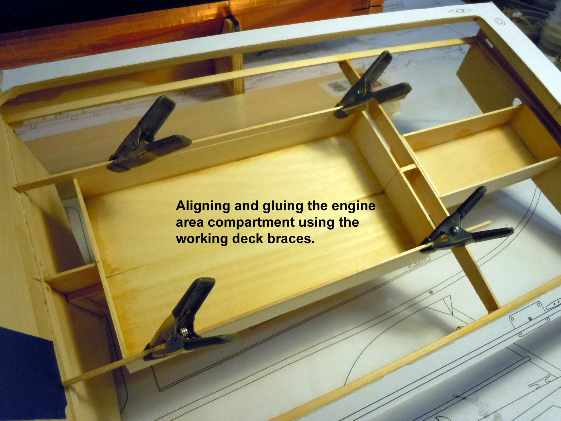
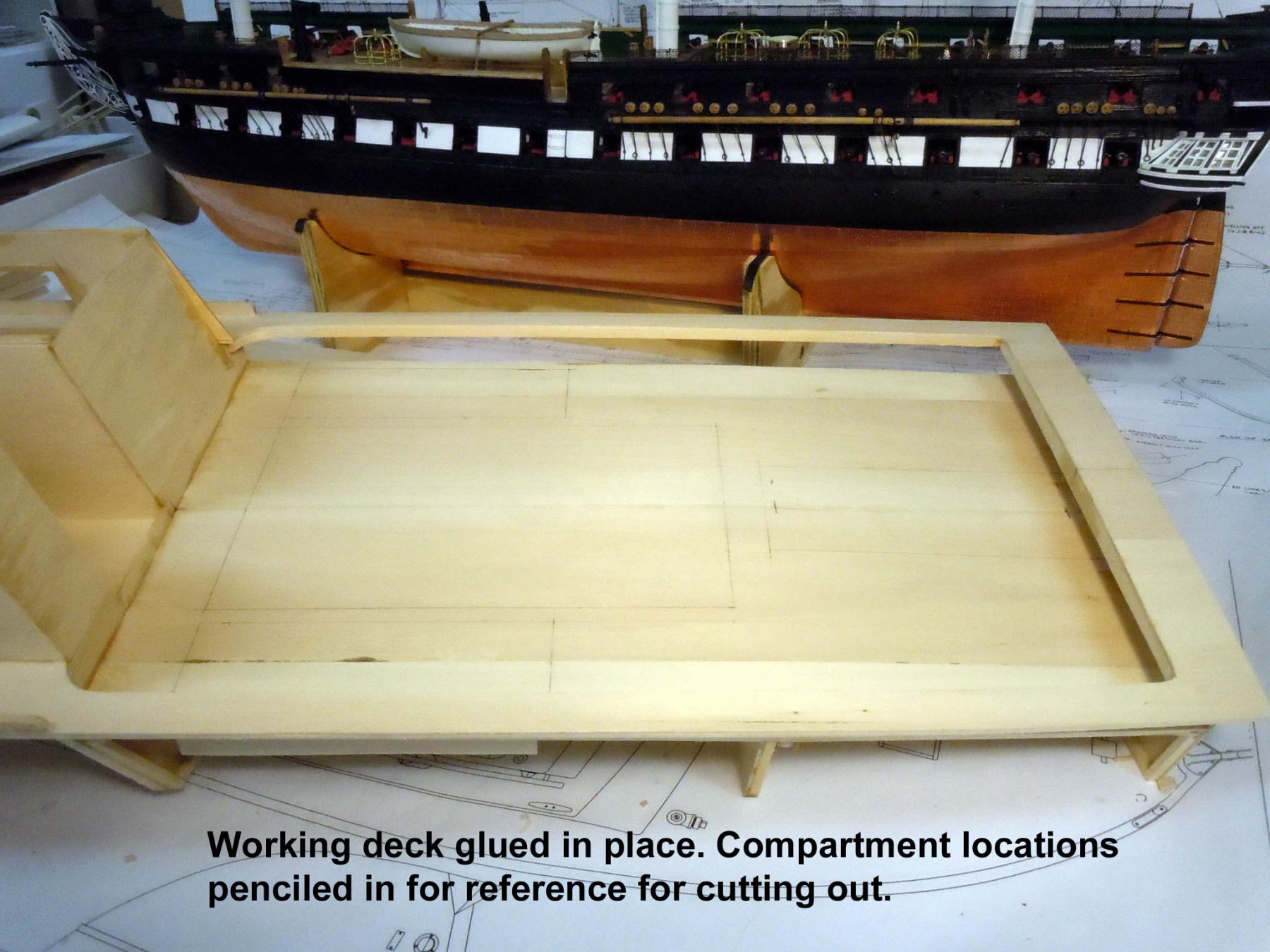
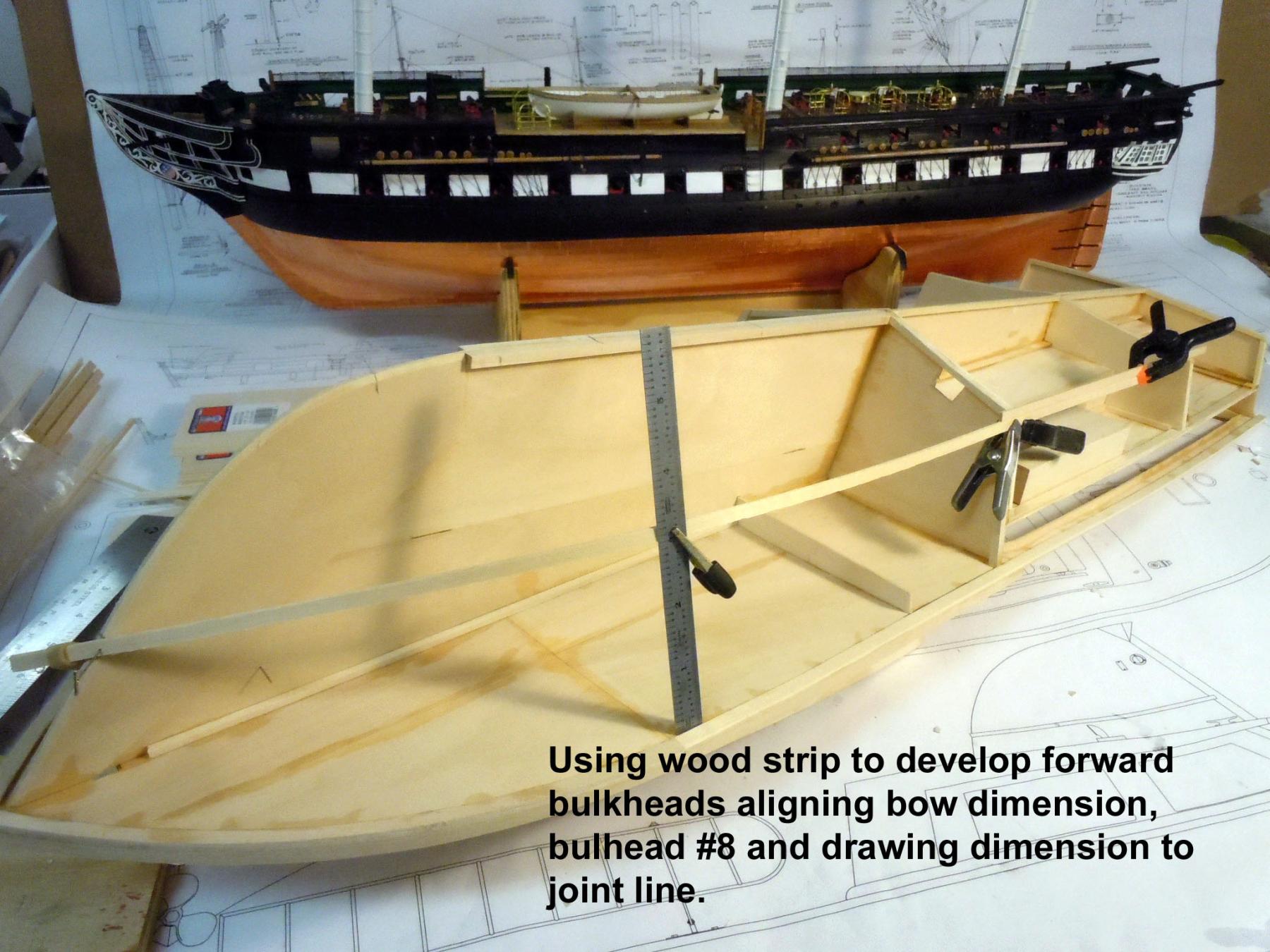
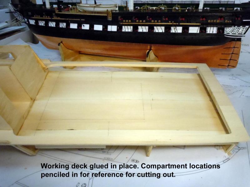
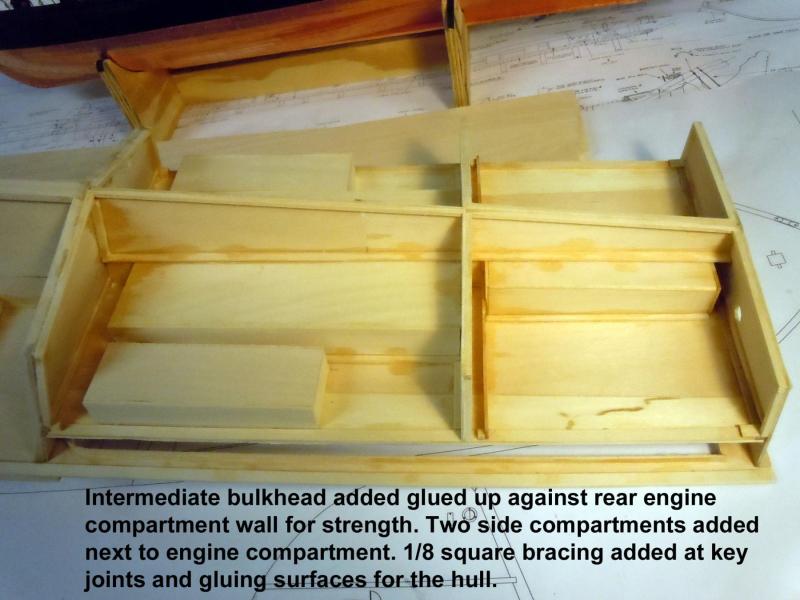
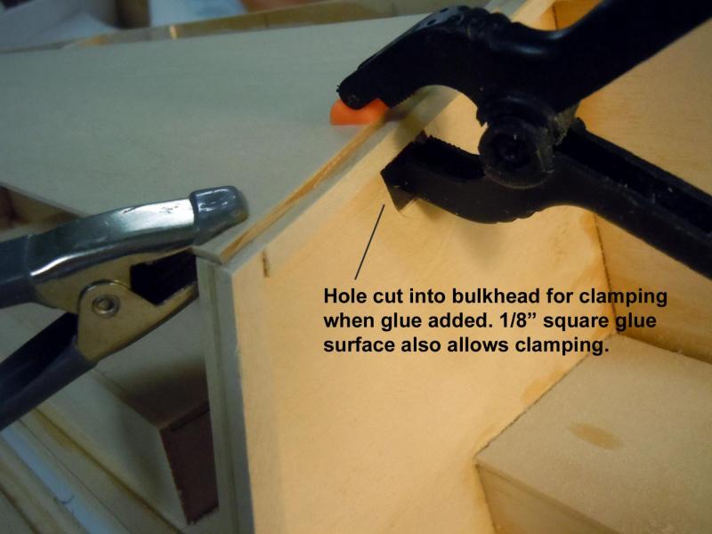
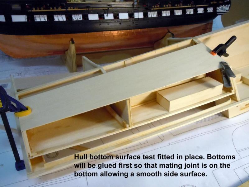
I moved on to the engine compartment and built up the basic box with with the top edges shaped to match the work deck. I located and glued it into position align on the center line and used strips clamped to the side to match the deck surfaces. Here is the working deck glued in place with the compartment locations penciled in for reference when it comes time to cut them out. I will leave the deck solid until the hull is completed for extra strength and reduced flexing. Once the deck glue was set I added the two compartments adjacent to the engine compartment. I am not sure what they were for but could have been battery and air compressor for the diver. Here they are in place. I also reinforced all key joints that will help when deck surface is cut away. I also added the intermediate bulkhead to develop the hull curve from the transom to bulkhead #8. I cut clamp holes in bulkhead #8 to assure a good tight joint when glued. Next I cut the bottom surfaces of the hull using a side piece to develop the tight edge joint. I will glue the bottom surface on first so that the side surface will be smooth and joint free when viewed. Next I am moving to the forward portion of the hull and using a 3/13 x 1/16" strip to define the hull sweep using the bow reference mark, bulkhead #8 and the reference dimension from the CAD drawing and clamping the strip to the ruler mark. From here I will develop the froward bulkheads. I am also pondering the notion of a solid carved nose section; but will decide that once the bulkheads are in place. Back to the front bulkheads.


- 162 replies
-
- 16
-
-
- dirty dozen
- fishing
- (and 2 more)
-
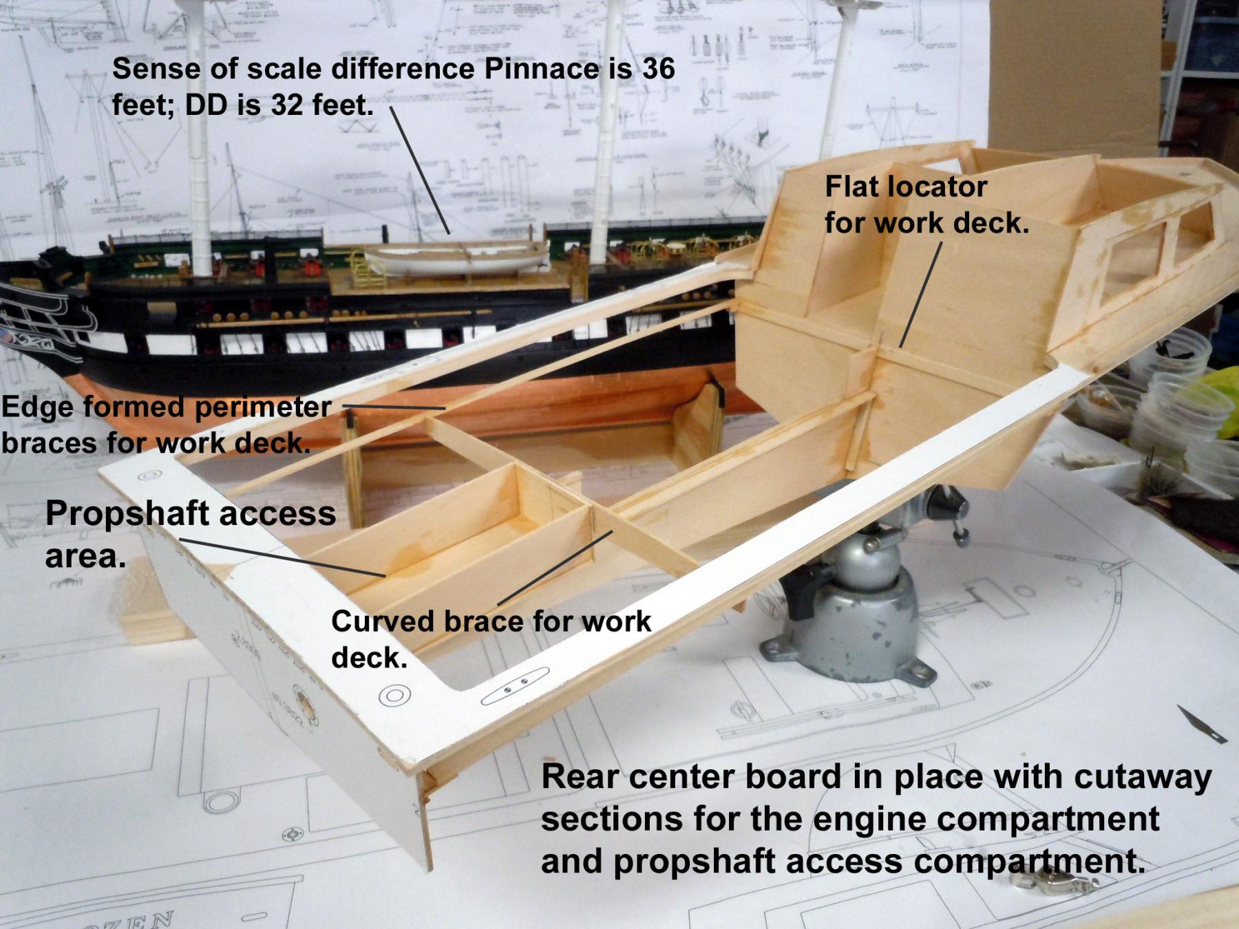
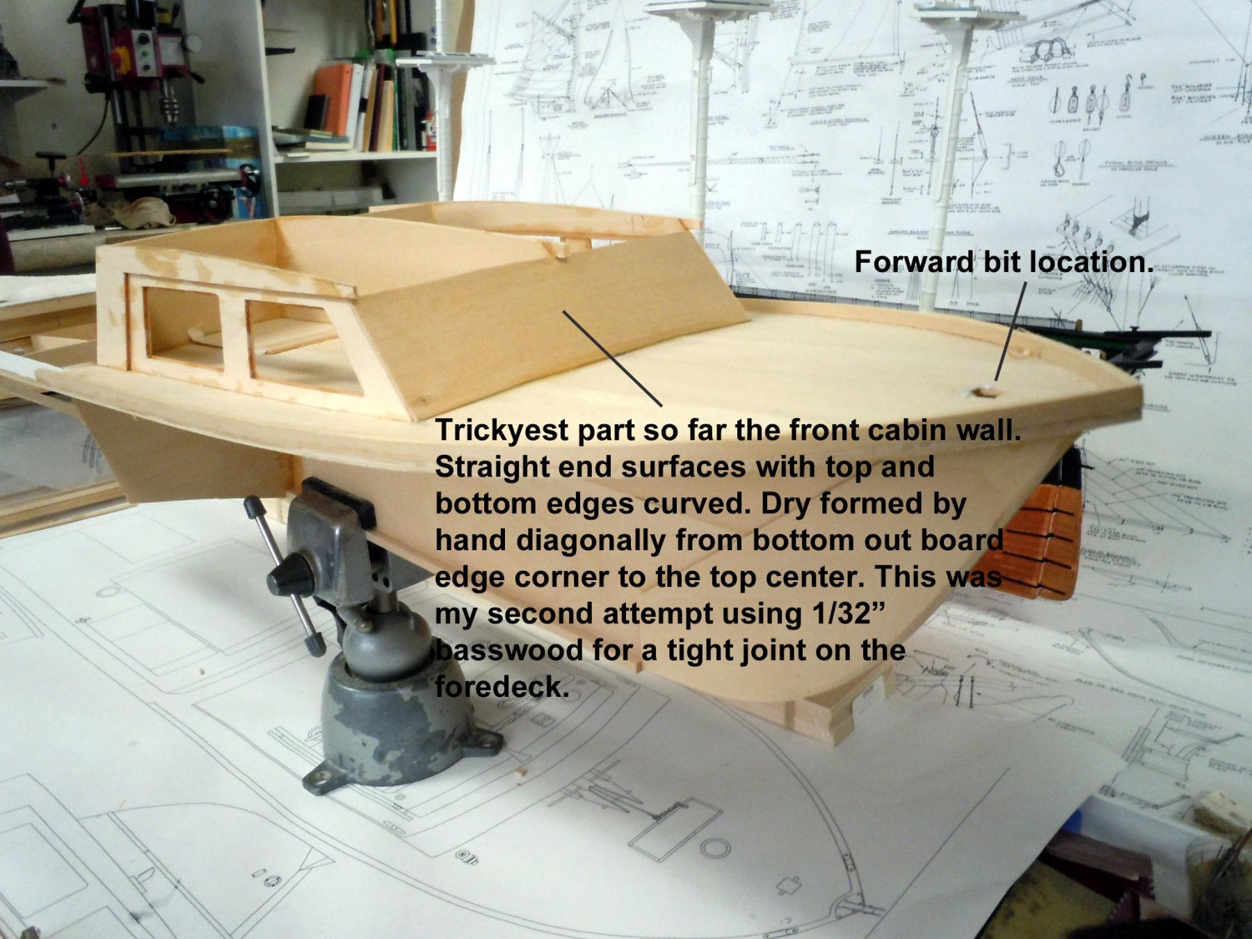
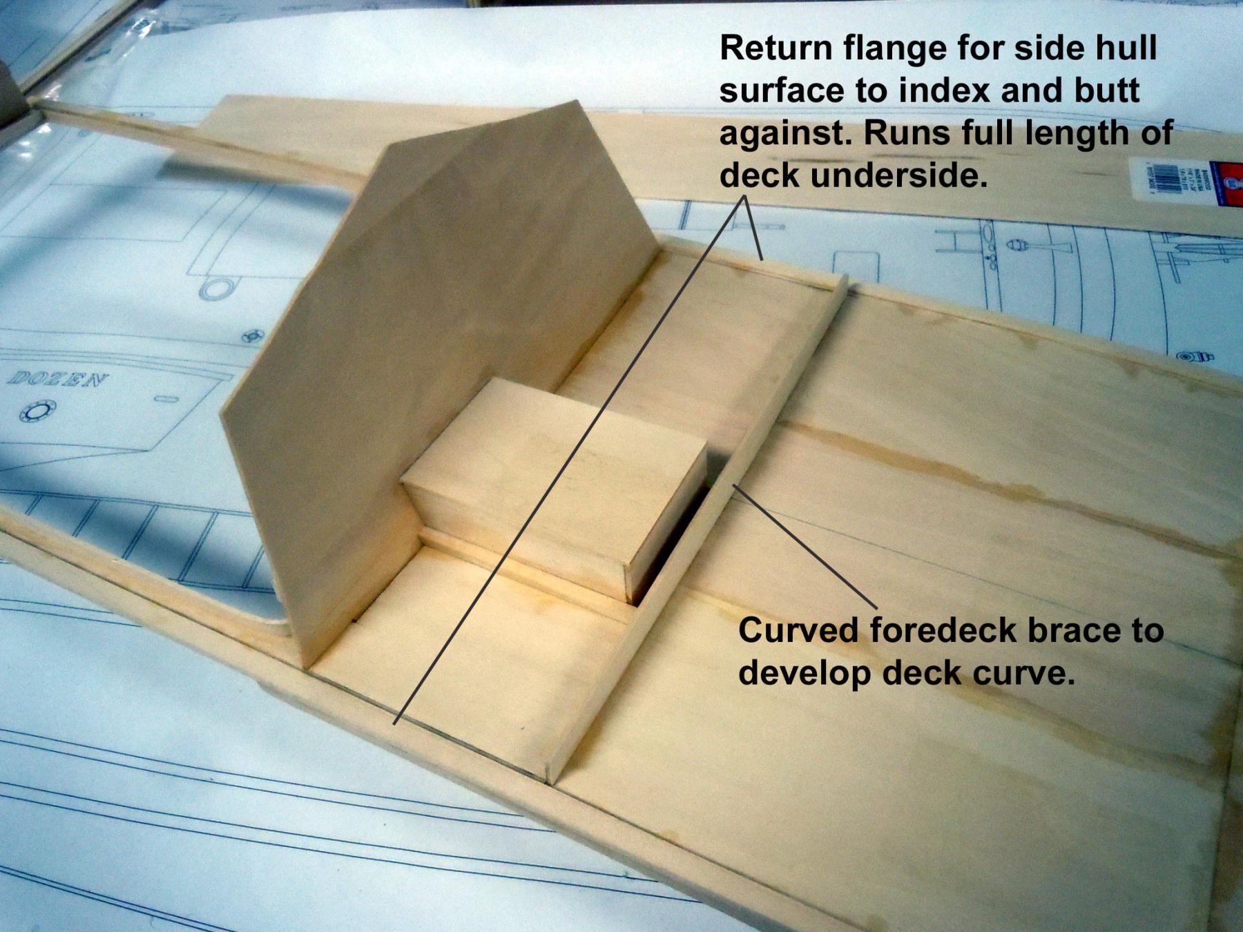
Bob, she is not there now, but could be out somewhere, I will keep checking time to time. Tom, it only appears fast but that is the advantage of drawing the plans in CAD because as you are drawing you are building it in your mind as well. I get my prints 34" x 22" D size for a $1.75 a print; sure beats tracing and I use the prints as patterns. I just have to keep in mind angled surfaces and wall stock cut for joints when cutting the wood. I added the return flanges for the working deck area to the underside of the deck. These needed the ends soaked in water to form the curved corners adjacent to the rear cabin wall. While soaking I added the curved brace to the rear edge by tracing the deck curve and then cutting to the correct center height. Then I added the center board from bulkhead #8 to the transom. Added stiffeners to keep the centerboard straight and provide a gluing surface for the compartments. I also glue up the working deck surface edge gluing 4 pieces to the needed sizes and while waiting for them to set I formed the working deck side perimeters by edge forming them dry since they are slight curves. I then added the prop shaft access area box with the top edge trimmed to the working deck height. These compartment are easier to add now and will provide structure as well as gluing edges for the working deck. While waiting for glue to dry I then added the cabin front wall which was the trickiest part so far with straight gluing surfaces at the edges but curves top and bottom and it took me 2 attempts to get a tight fit at the fore deck. I dry formed it by slowly and carefully bending diagonally from the lower side corner to the upper center to develop the curve. The part was slightly over sized side to side so once glued in place the edges were trimmed to match with a sharp blade. I also had to go buy a second bulk pack of Basswood sheets. Just a tip; if you have an Ace Hardware in you area I buy a 15 sheet bulk pack much more cost effectively than other wood outlets. Now to build the engine compartment before adding the work deck surface. This will help define the need bulk heads for the hull.


- 162 replies
-
- 11
-
-
- dirty dozen
- fishing
- (and 2 more)
-
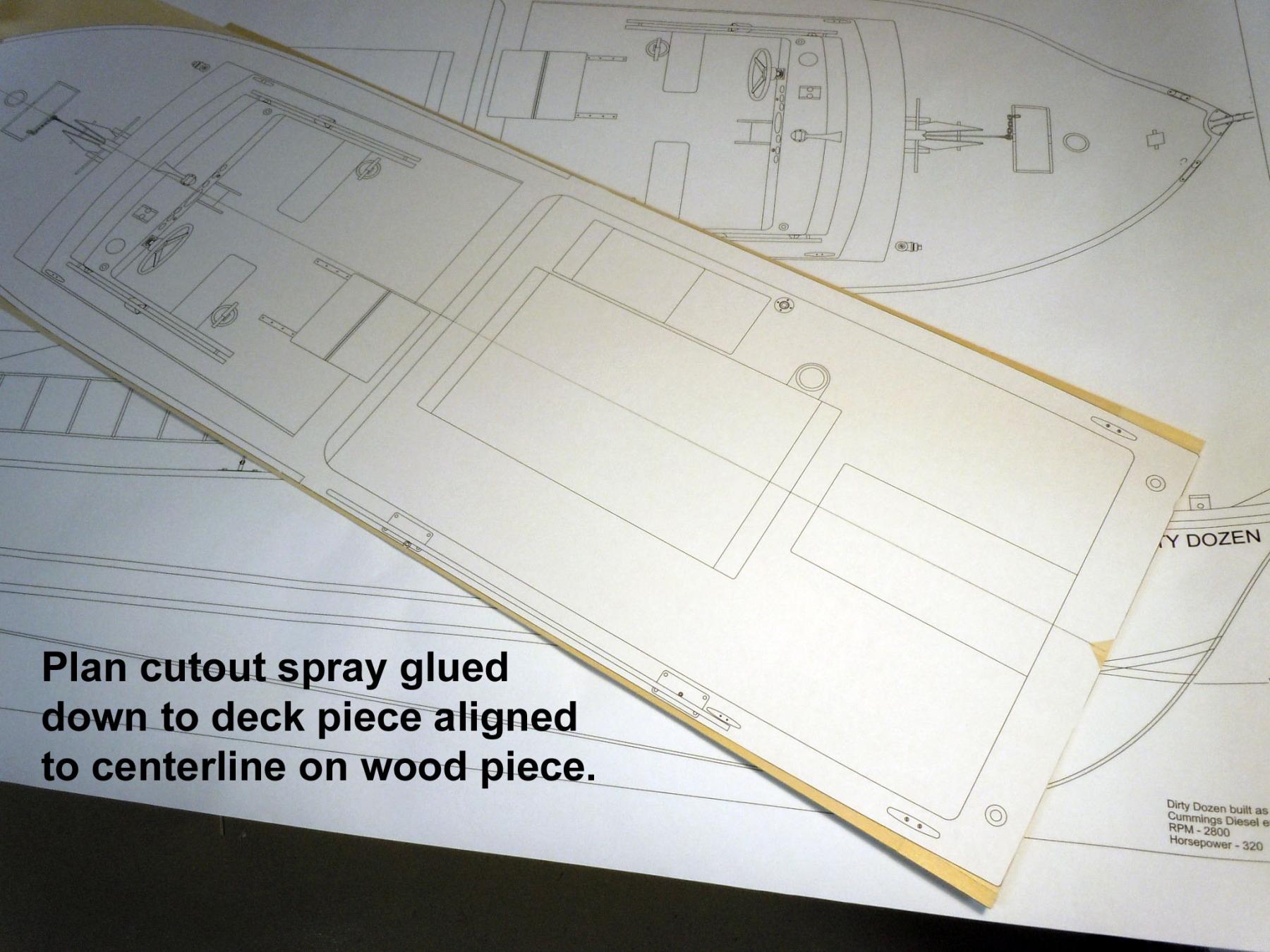
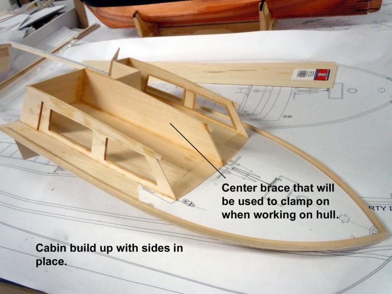
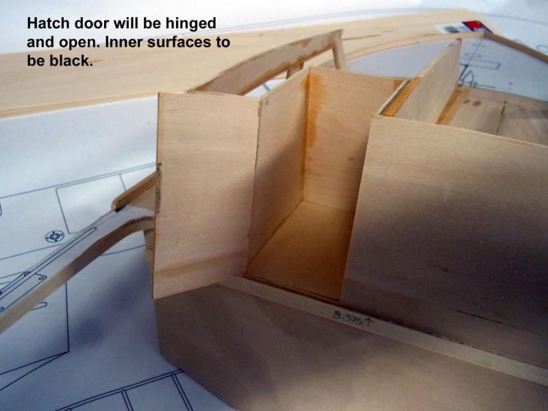
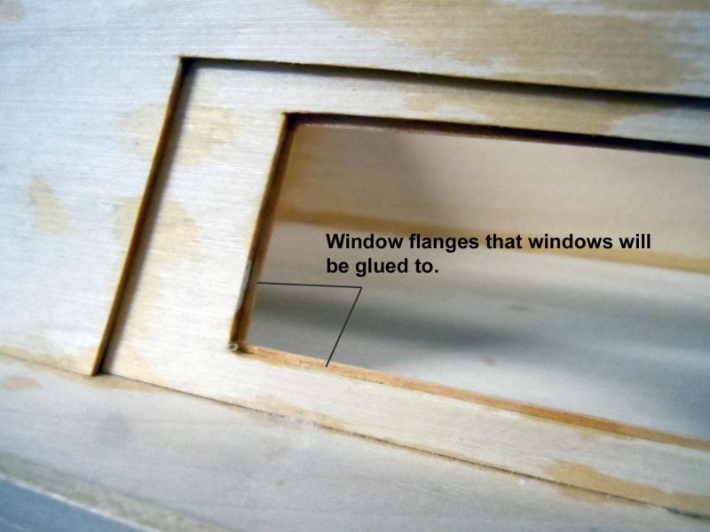
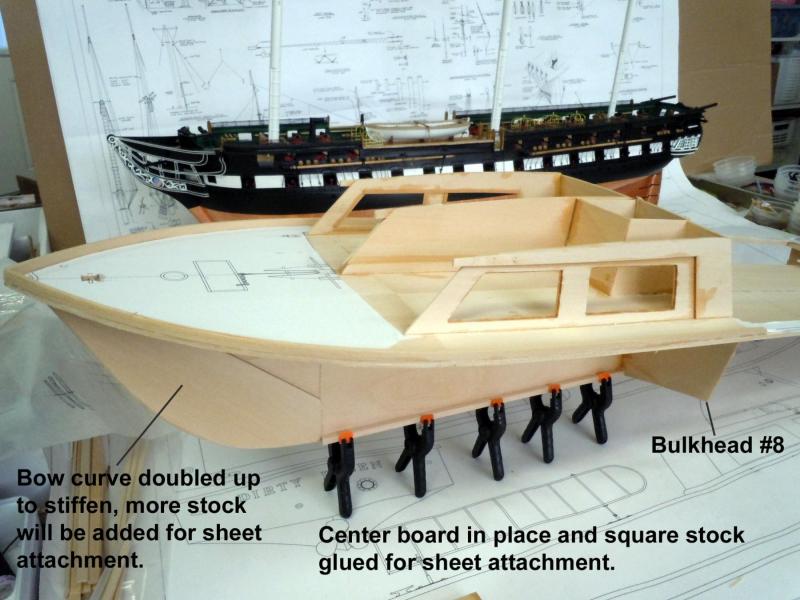
I added a deck brace to develop the curve from the forward edge of the cabin area to the bow. Next I build up the cabin sides with window flanges to provide gluing surface for the windows. I also added a center piece to provide a clamping surface while working on the hull. The cabin roof will go on once the hull work is done. Here is a picture showing the hatch door open This shows the window flanges using .020" strip stock. Here I added the center board of the forward section of the hull with edges pre-carved with slight angles. Again I used the prints for patterns. When gluing the prints to the wood I use 3M 77 spray glue with a light tack coat to lightly stick to the wood. To remove the print I just wipe with a coat of lacquer thinner and then clean off the glue residue with more thinner. Next I will move to the rear working deck area and add the center board there.

- 162 replies
-
- 14
-
-
- dirty dozen
- fishing
- (and 2 more)
-
Bob , next time I am down there I will check to see for you. We get many fishing boats that visit here from up north. Is she a local boat?
- 162 replies
-
- 3
-
-
- dirty dozen
- fishing
- (and 2 more)
-
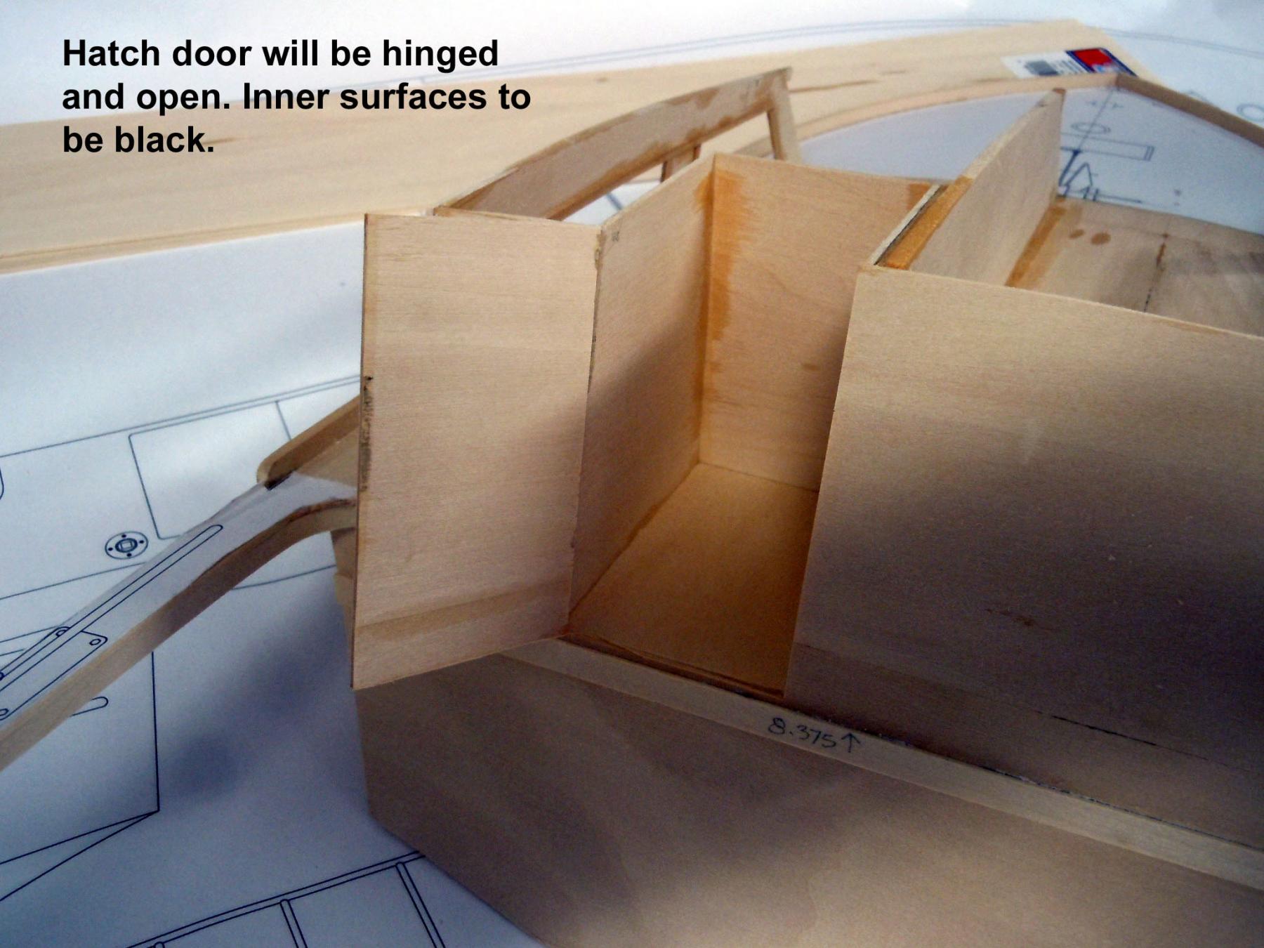
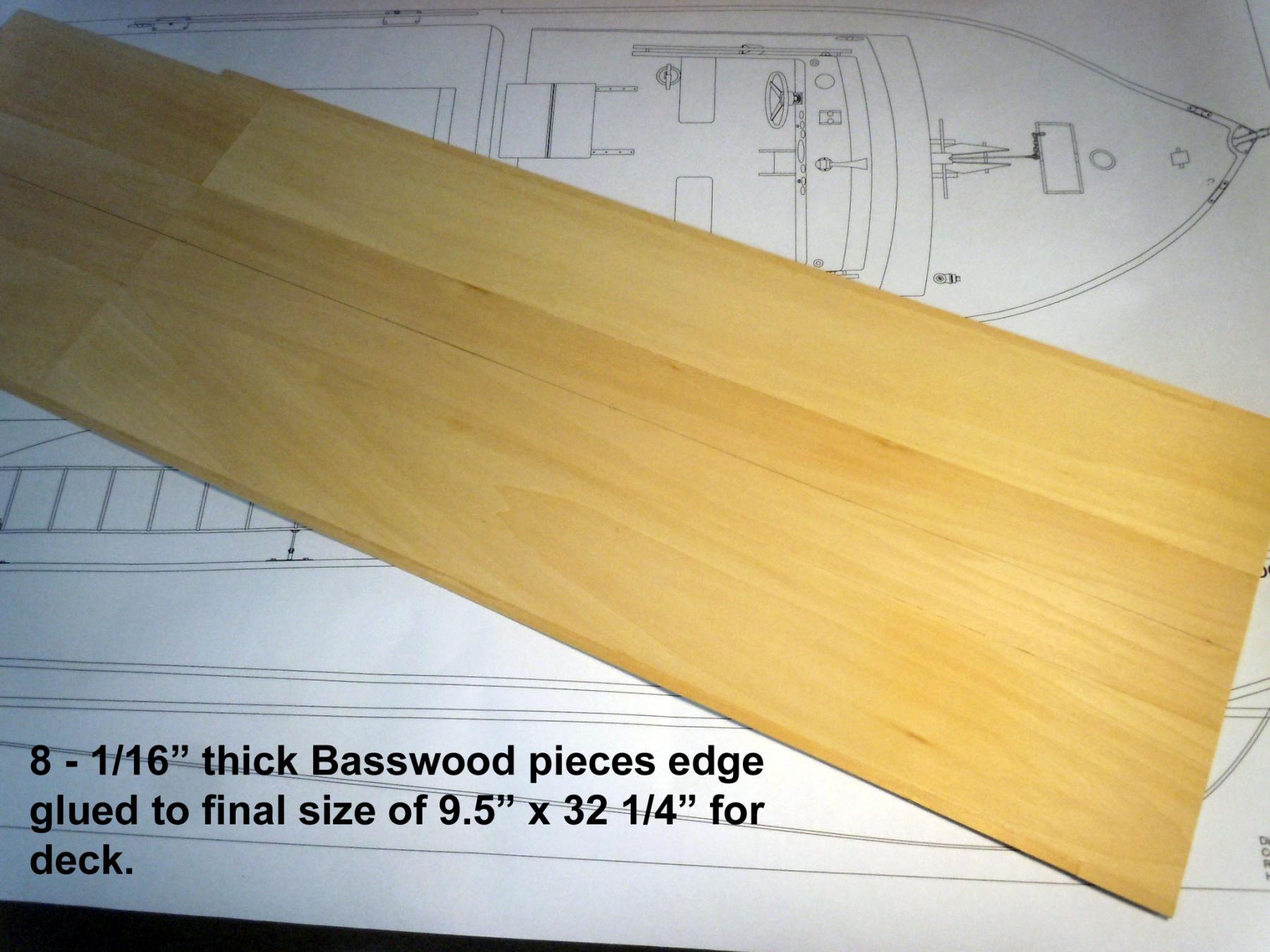
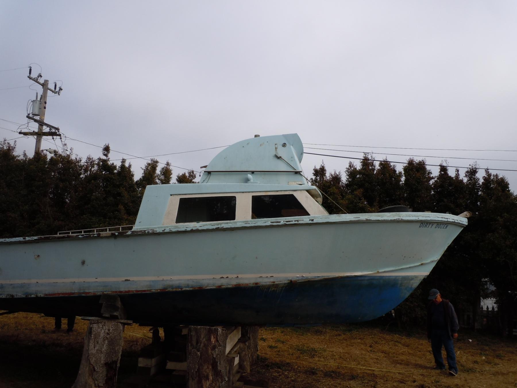
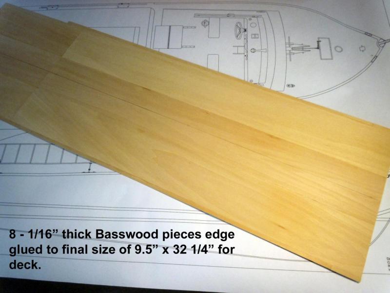
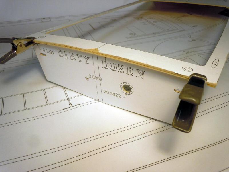
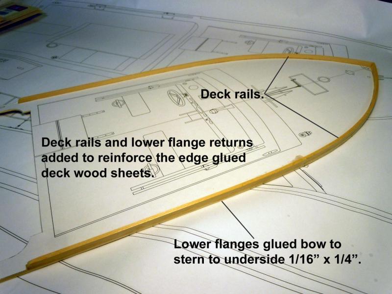
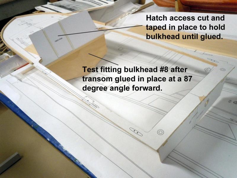
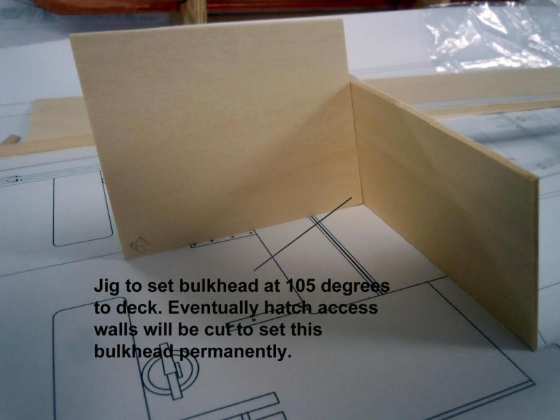
With Kurt's encouragement I am stepping into the Darkside of scratch building a boat and I might add much sooner than I thought. This build will run in tandem with my Constitution build. This build is a commission for the local Maritime Museum here in Morro Bay in which the building is in the process of starting to build with a targeted completion date of October to correspond with the Boat Festival. They have requested a 1 inch to the foot scale model with an overall size of 32" long. My first step was to laminate together 1/16" thick x 3" Basswood sheets to the plan size of the deck. The real boat was a local marine grade plywood build with a Cummings diesel engine. I did enough of the CAD drawings to get off to a good start and I use the CAD prints as patterns to cut out parts as seen in some of the following build pictures. I am not new to scratch building models and the interesting thing is that there are no instructions and plans unless you obtain them or draw them. I use CorelCAD to make the basic rough drawings and then print out what I need as I progress and often refer back to the CAD files as I build for dimensions. One thing about scratch building is that it is much like playing chess and one has to be two or three steps ahead so as not to build yourself into a bad situation. The other thing that happens is off hand building in space and building in structure as you go. Here are images of the build start on Saturday beginning with the sheet glue up and building in structure with rails and flanges to strengthen the deck sheet. To establish the deck curve I built up the transom and will progress building from the stern. The transom flange was cut to 87 degrees relative to the deck. The beauty of having the CAD file is exact degrees when measured in the computer file. Here the rails and flanges were added for strength and hull set back indexing edges with the flanges. Next I moved onto bulkhead #8 which is angled and forms the rear wall of the cabin. I also pre cut the hatch door and taped it back in place to maintain part geometry. The horizontal supports for the working deck has been added to #8 as well as the inside of the transom aligning with the supper holes. Next I made a 105 degree jig for the bulk head this will be used to develop the geometry for the false interior that will be blacked out. I will attempt to have a work hatch door with sliding access panel. Next I plan to move to the forward cabin for additional structure and strength before moving to the hull.


- 162 replies
-
- 11
-
-
- dirty dozen
- fishing
- (and 2 more)
-
Geoff, Thank you for your kinds words. I am bonding with my ropewalk making various thicknesses of black standing ropes for shroud lines and stay lines. Not exciting work but needs to be done. I am using the DMC Cebelia 310 #'s 10; 20 & 30 crochet thread. Great stuff to work with and I am making 4 foot lengths at a time. Kurt, with years of experience as a product design consultant and corporate executive one major lesson I have learned is that regardless of the project people basically want " The Hope Diamond for a quarter." So you are correct in establishing the expectations up front and then exceeding them upon completion, for a happy customer. On this build I know up front that I will be donating some of my time to get the Maritime Museum up and running and that there will be more builds down the road. I really have no problem at this point in time in giving back to the community that I live in; which I have done most of my life as I could wherever we lived. I am a firm believer that if you do not invest in the future you will not have one. http://www.morrobaymaritime.org/about.html Back to rope making.
-
Tom, she is looking great! Keep up the great job you are doing. Ken
- 1,348 replies
-
- 3
-
-
- constitution
- model shipways
- (and 1 more)
-
Kurt, would I post it in the "Scratch build" section or someplace else? It will be educational for me as well.
-
Finishing up the rough in drawings for the Dirty Dozen and forwarded them to the Maritime Museum President for the nod to move forward on building it. Here are a couple of "in progress" drawing files. Dirty Dozen.pdf Lofting Lines.pdf In the meantime I have been making black rope of different sizes for the standing rigging and will be busy for awhile.
-
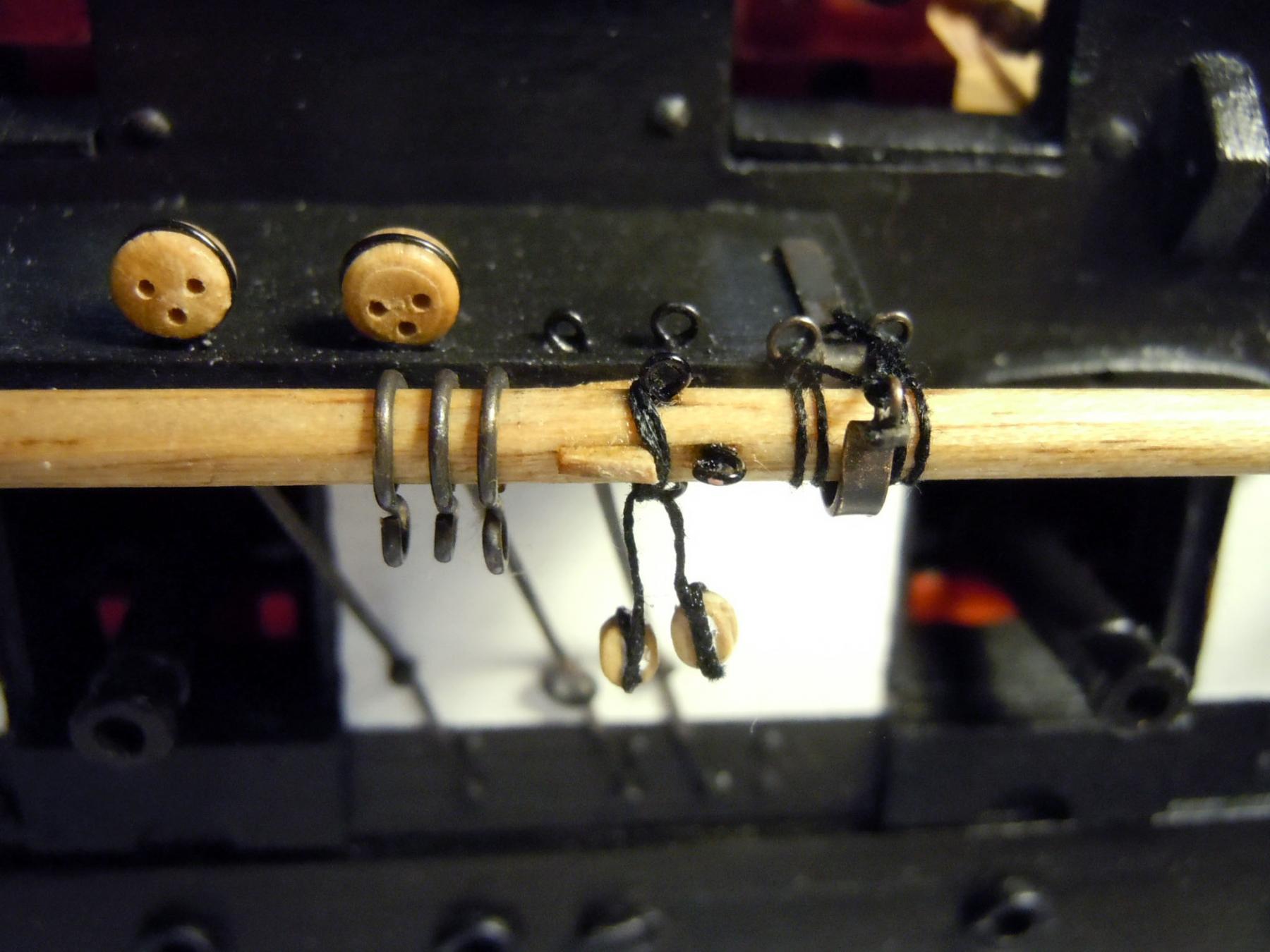
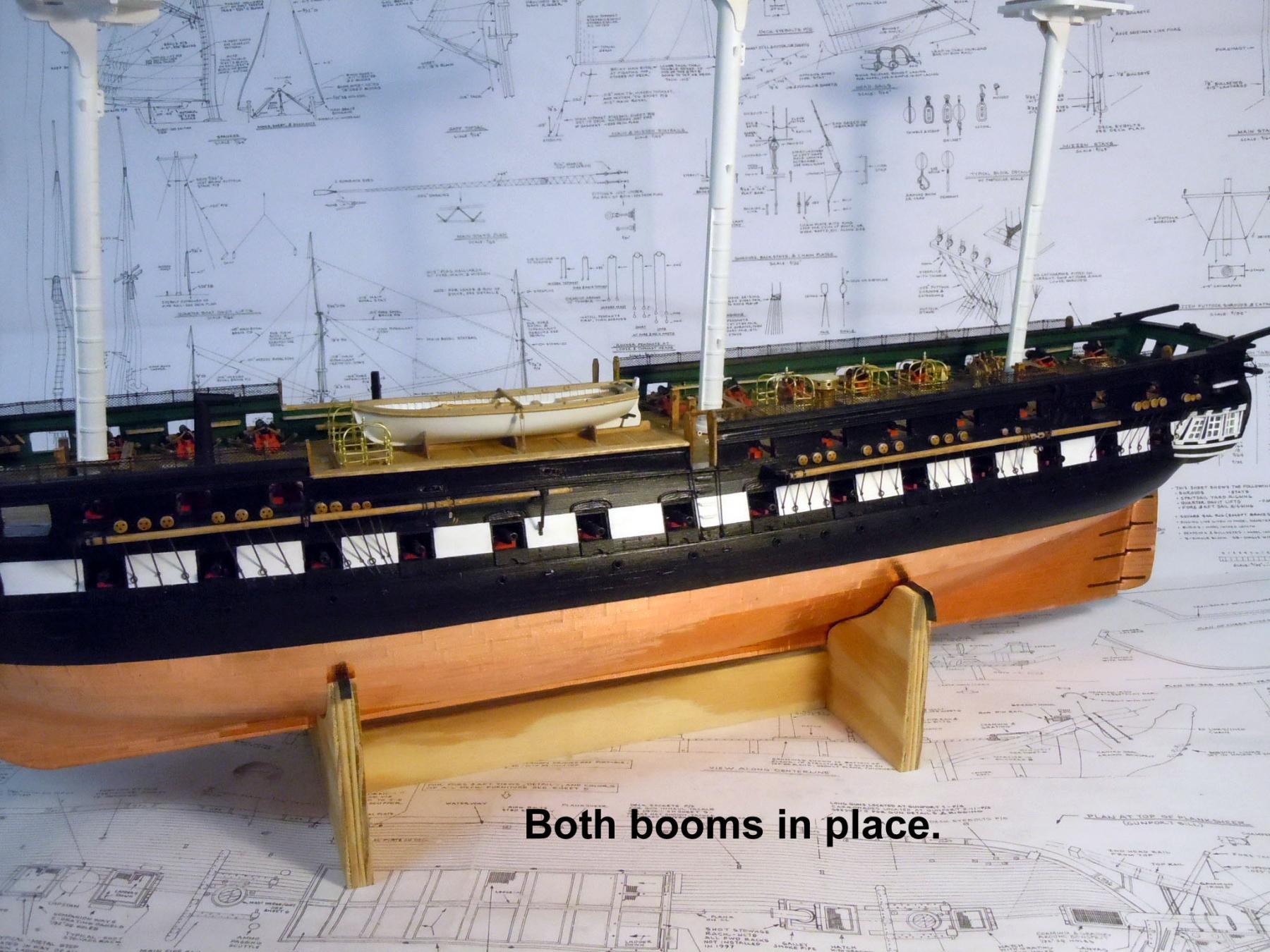
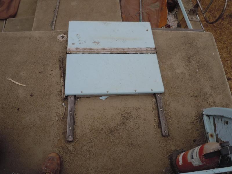
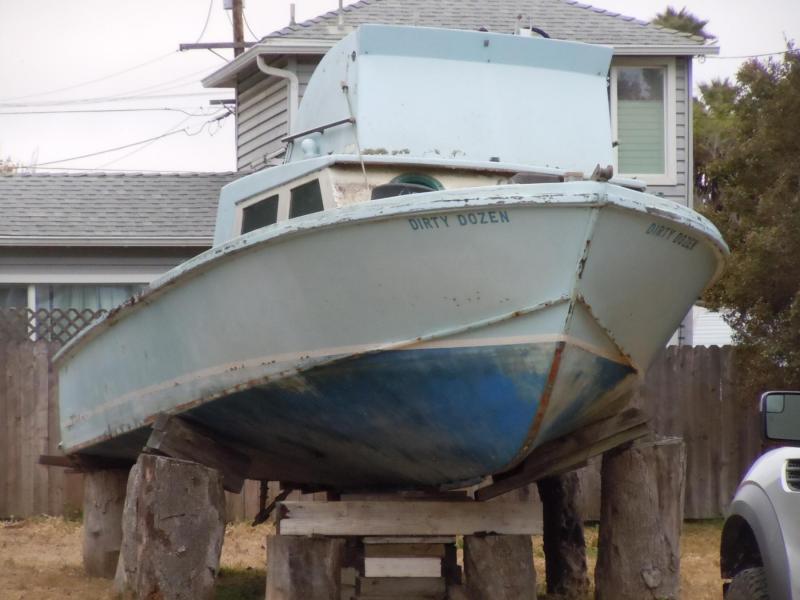
Mark, just a misunderstanding no need for the corner. I finished up both waist studding sail booms. Here are pictures of details and overall views they are done pretty much the same as the forward ones. Only major difference was the support brackets on the channel versus a support bracket mounted to the hull. I have no information on the bracket locations and if someone does please advise. I also got word from the local Morro Bay Maritime Museum to start the CAD drawings for the first abalone fishing boat that they want for a display. Morro Bay I guess was the capital of the abalone fishing industry years ago and this will be the first major display to be done. Looks like I get to do my first scratch build sooner than I thought. It will be 1" to the foot scale for a 32" long model when completed. The boat subject is a very well known local fishing boat called the "Dirty Dozen" that was built in Morro Bay using plywood that was later clad with fiberglass. I was able to document and photograph before it was broken up earlier this year. Not as glamorous a build as the Constitution but will still be a little challenging for a scratch build and a chance for me to support the local museum effort. Here are a couple of pictures and as you can see it was rough. I will now be working on both projects as time allows, the deadline for the Dirty Dozen will be sometime in the fall of next year when the first phase of the building is completed.


-
Mark, I was referring to the studding sail boom for the mizzen mast swinging out from the hull like the two seen in the picture that I think you are calling the lower one.
-
Captain Steve, the booms fold back towards the stern along the channels. I will add the main boom as I did the foremast one already built. Same size and securing brackets. Stay tuned I will post pictures once completed.
-
Captain Steve or others...I have read mixed reviews about the AOTS-USS Constitution what are your opinions about the book? Is it worth purchasing for reference material? I value more the opinions of those who are builders and using the book. Also if someone has a used one for sale I would be interested in buying it. Let me know if you have one.
-
Tom, boat fittings are looking great! I will follow in your footsteps since I have not made these yet on my build. Keep up the great job you are doing.
- 1,348 replies
-
- 2
-
-
- constitution
- model shipways
- (and 1 more)
-
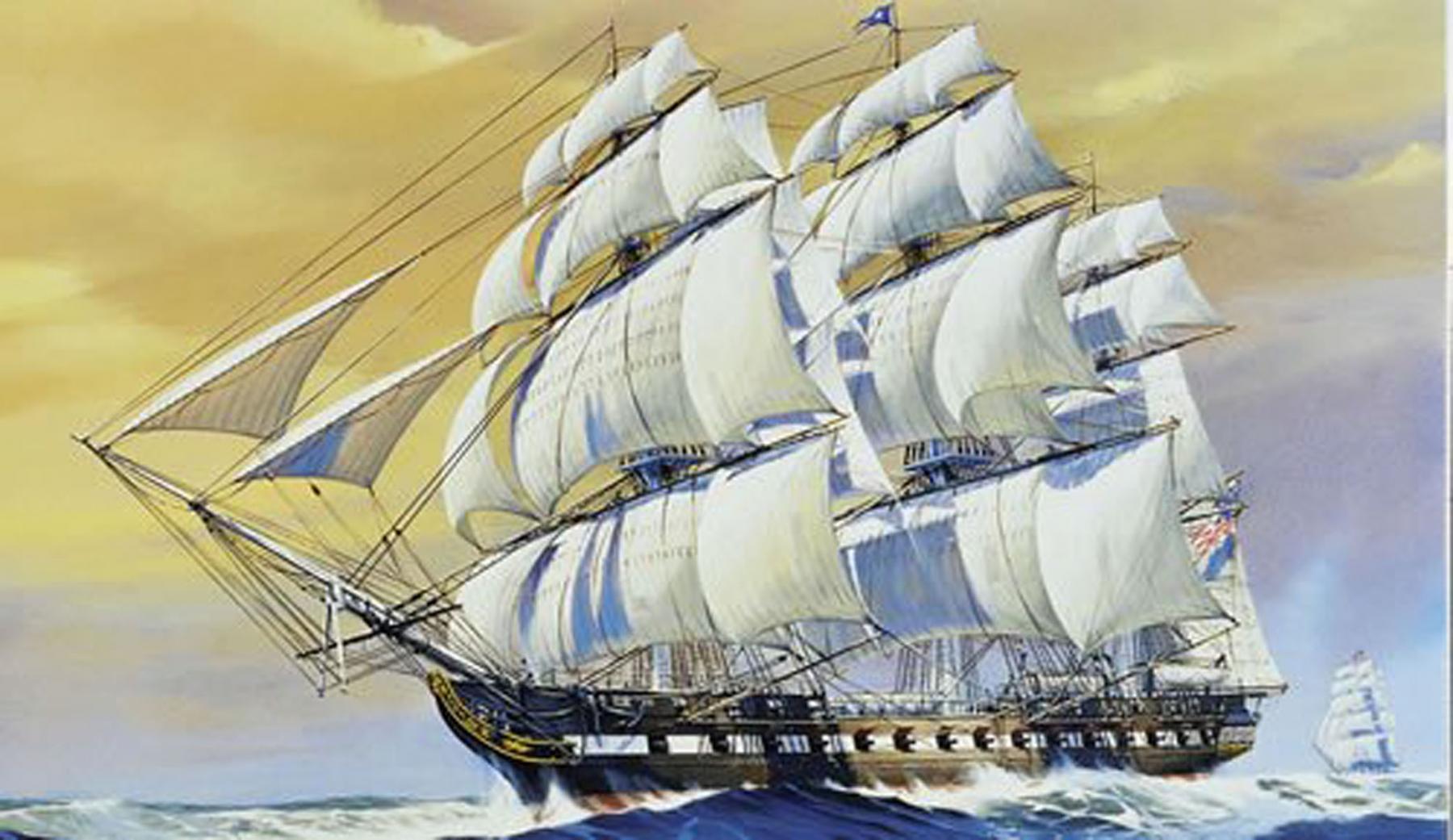
Rich, not sure yet about adding the hammocks. I will do some experimenting first. Captain Steve, looks like I will be adding two more booms. Thanks for your efforts! I am looking at purchasing that book since the illustrations look great and show much more detail that I may need down the road. Here is one of the pictures that I was referencing that clearly shows both fore and main booms deployed under full sail. No mizzen though. Back to making the two additional booms.