xken
-
Posts
841 -
Joined
-
Last visited
Content Type
Profiles
Forums
Gallery
Events
Everything posted by xken
-
 Greg, great idea just wondering how big a magnet would be need to get through the pinnace as well.
 -
George, good idea and will have to see when I get that far.
-
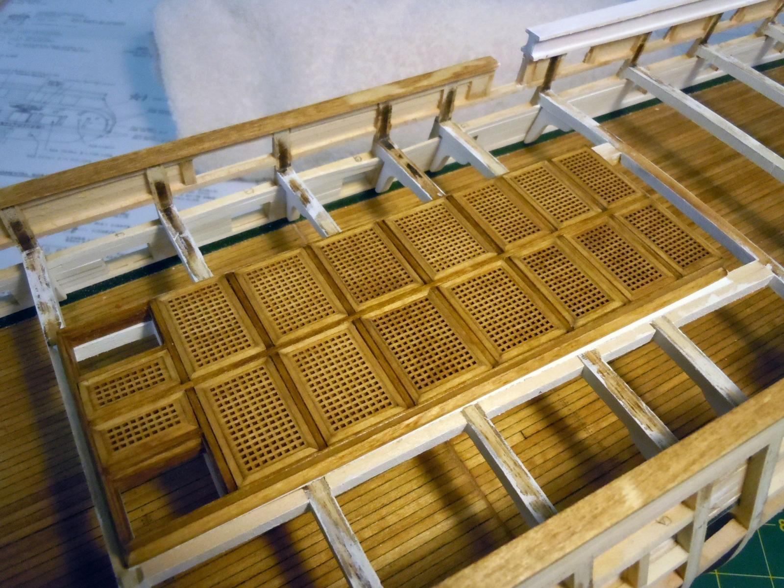
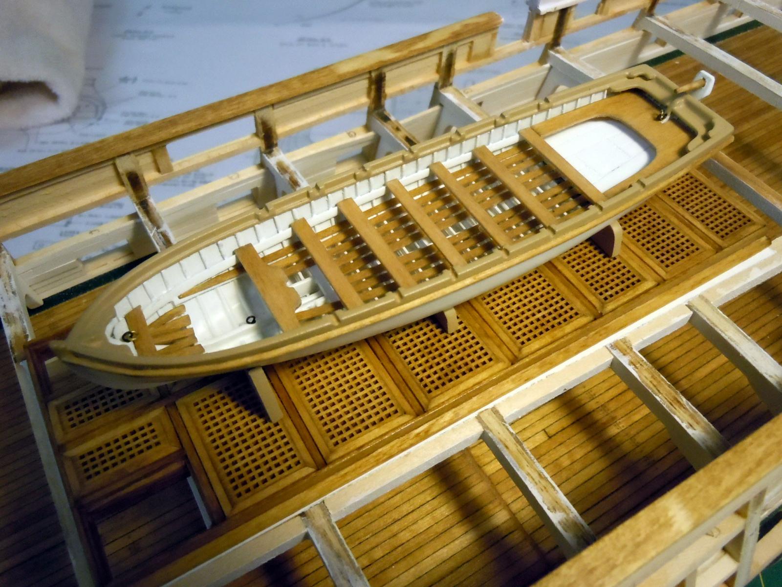
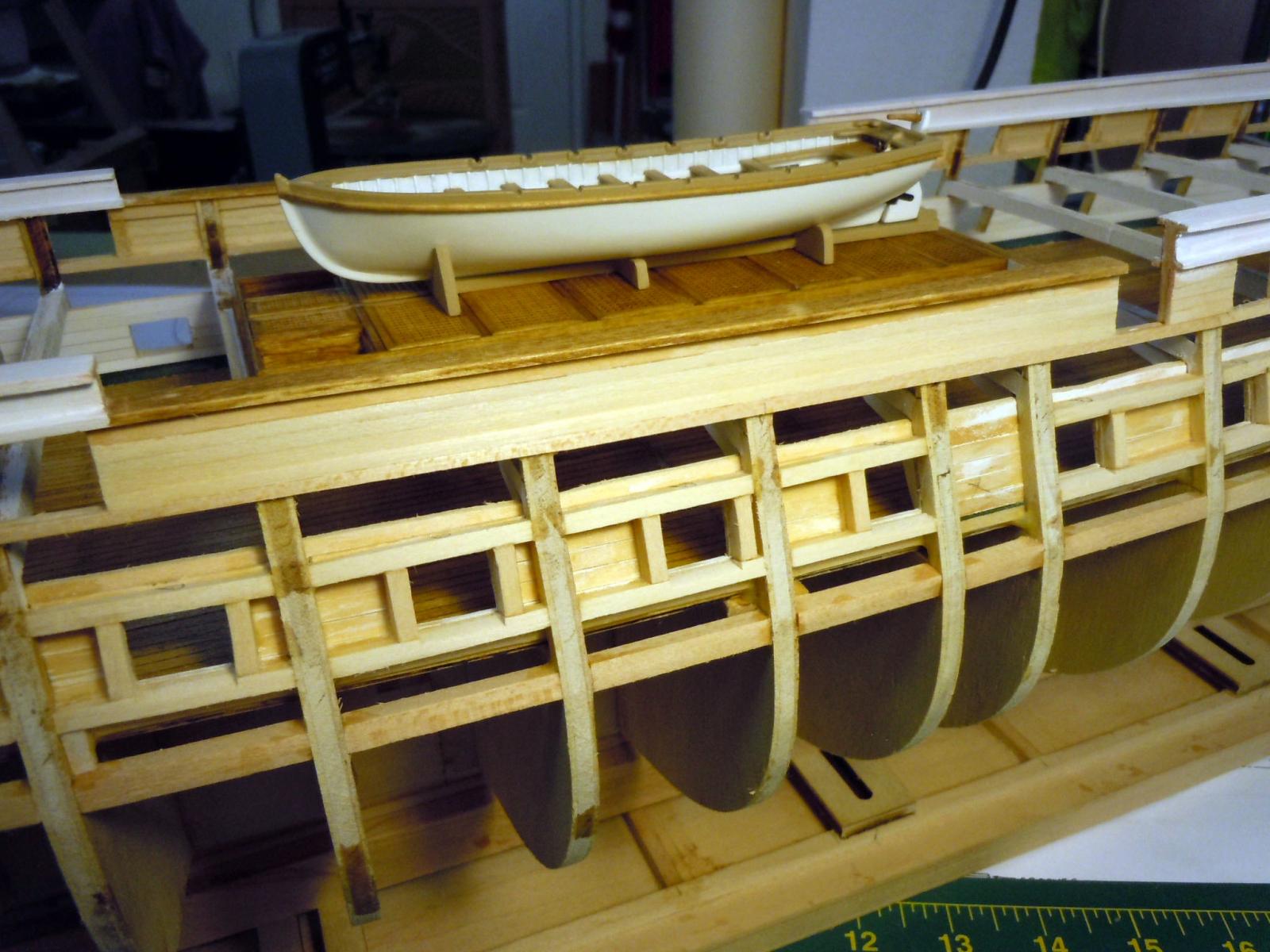
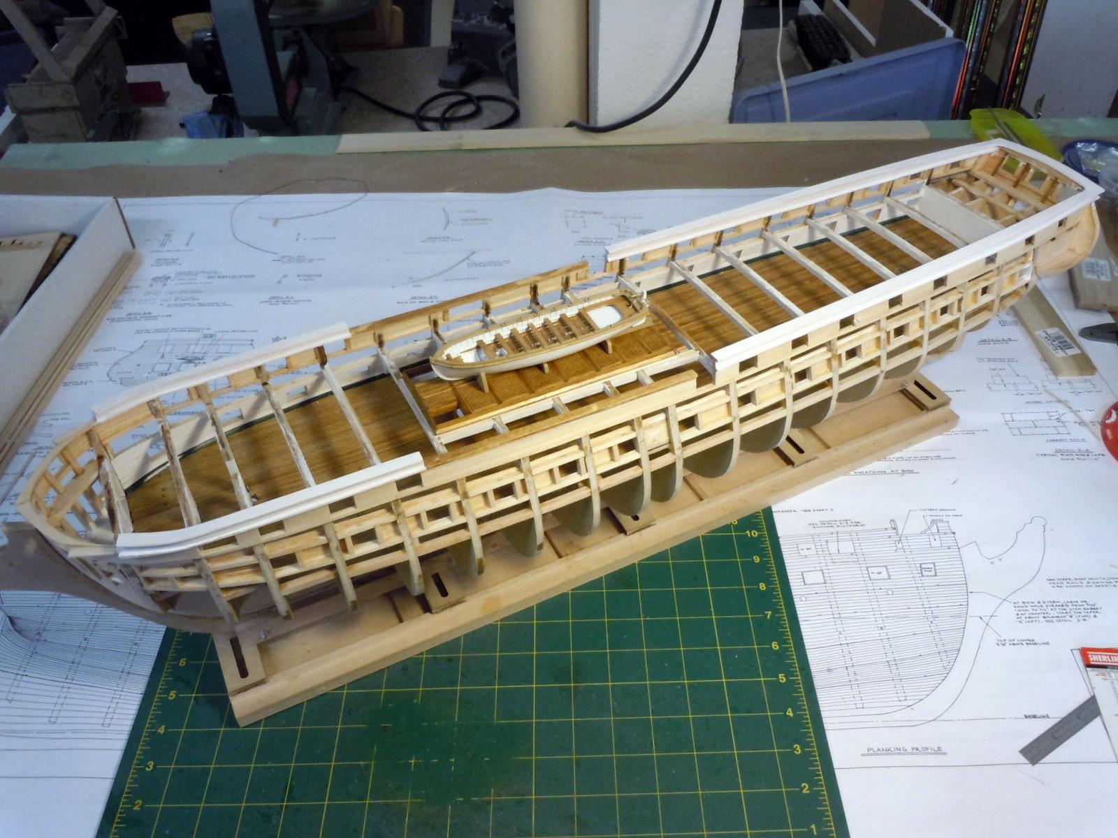
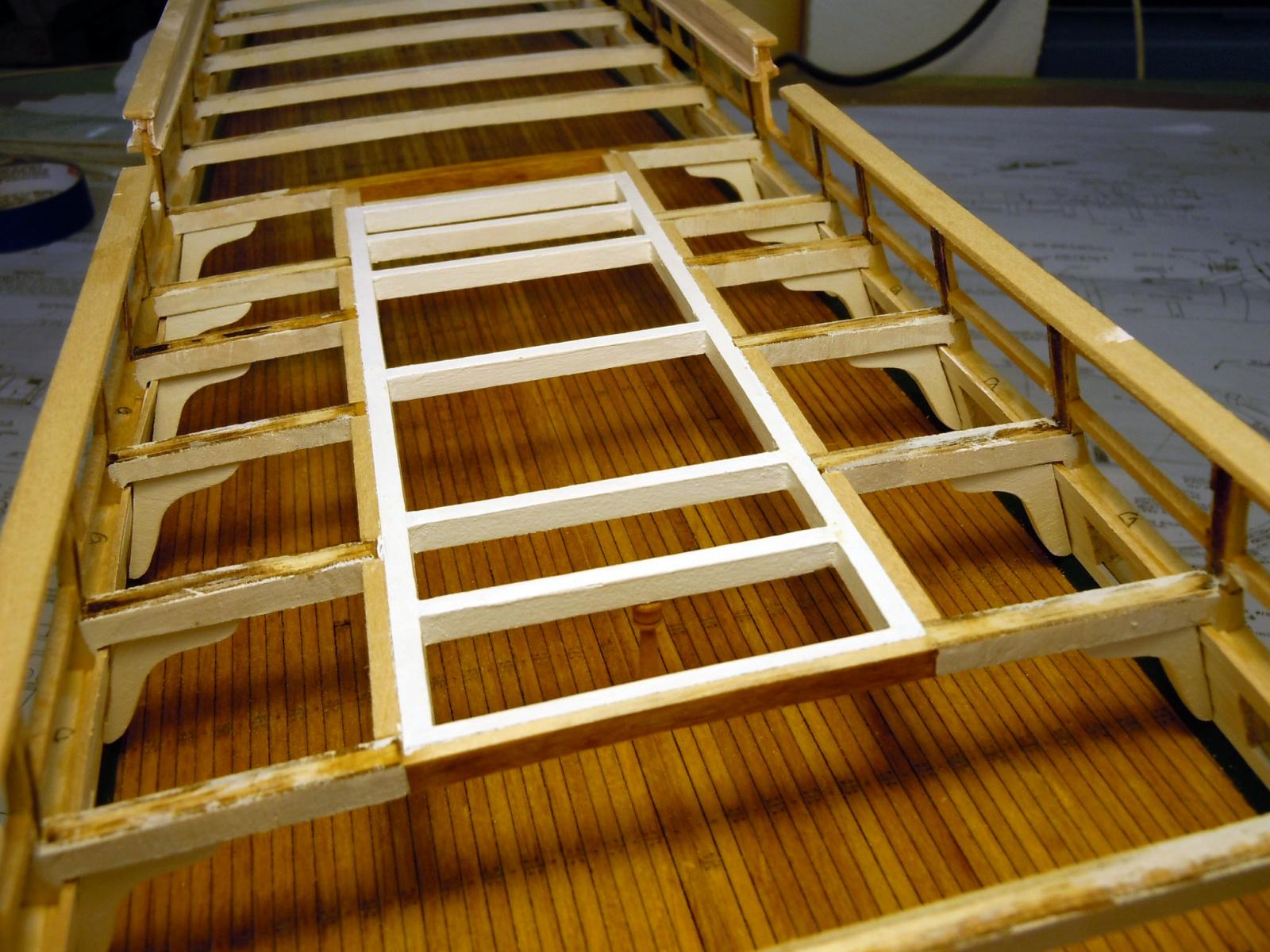
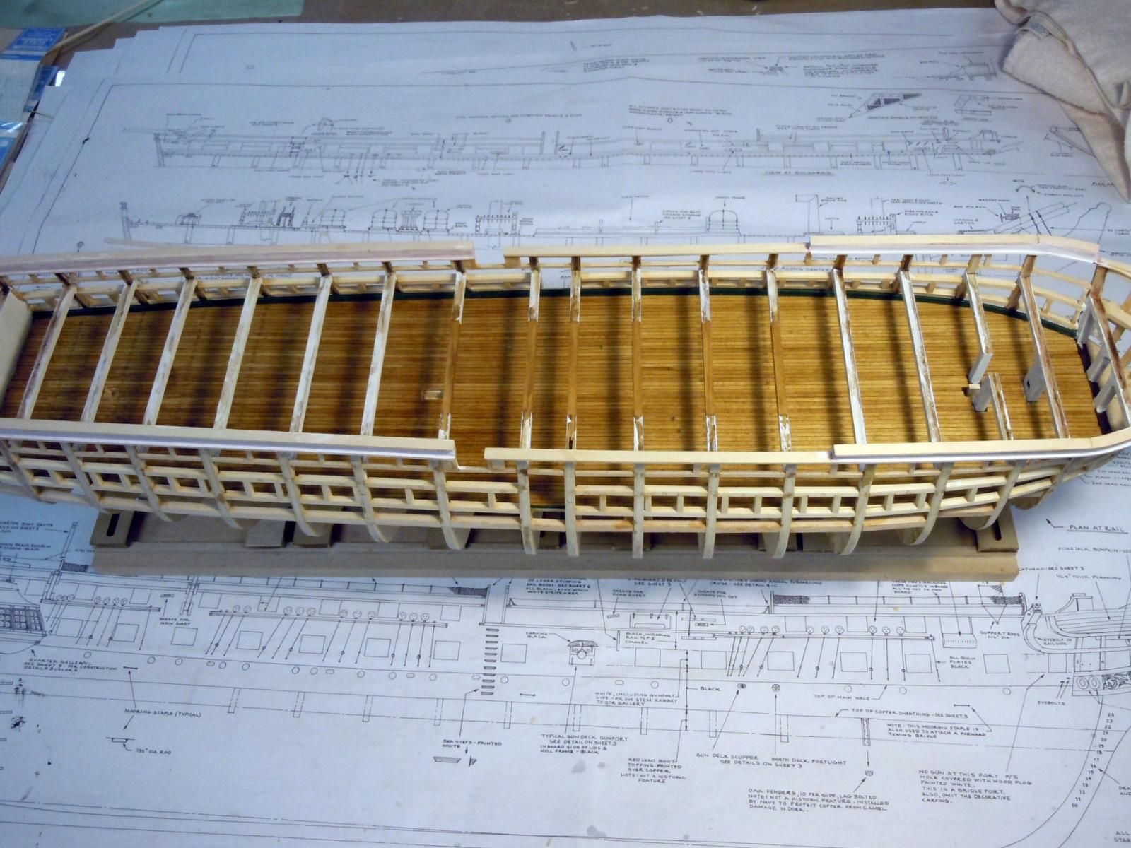
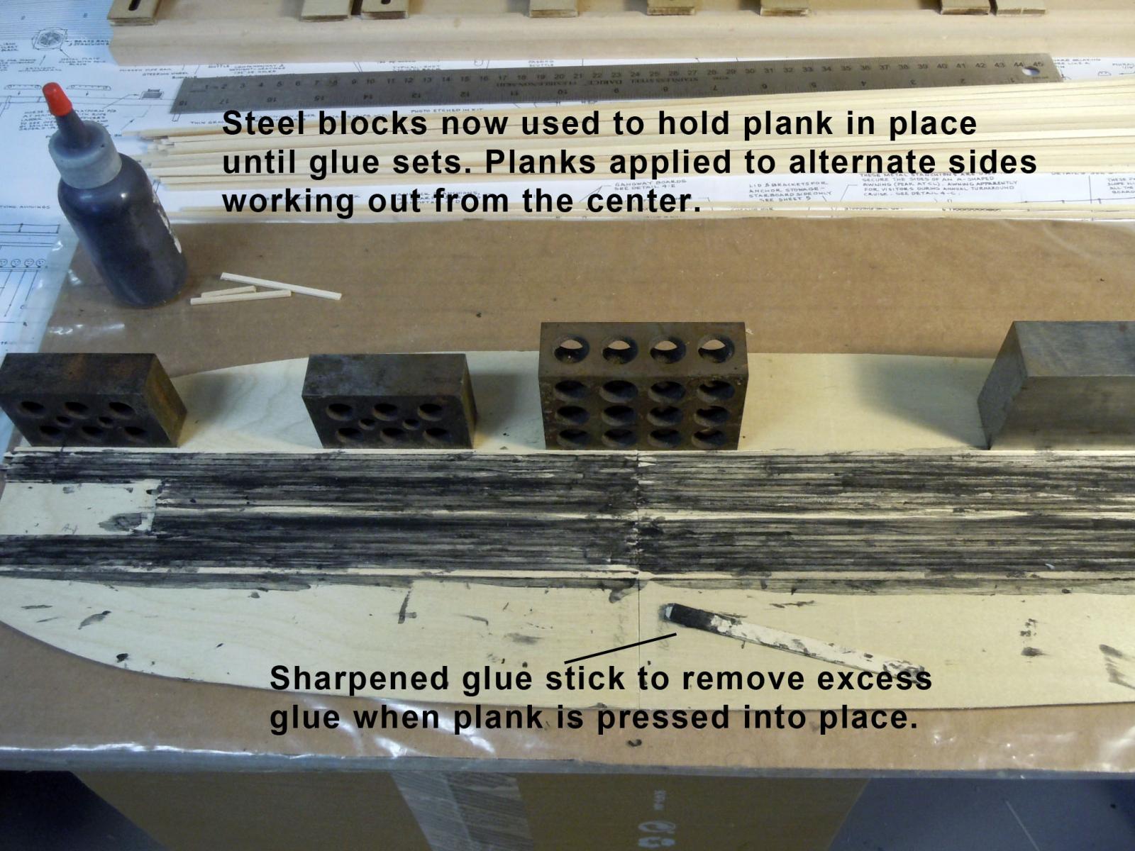
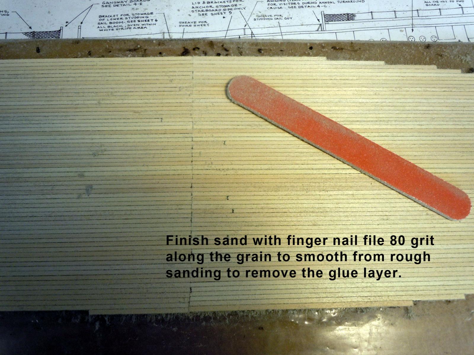
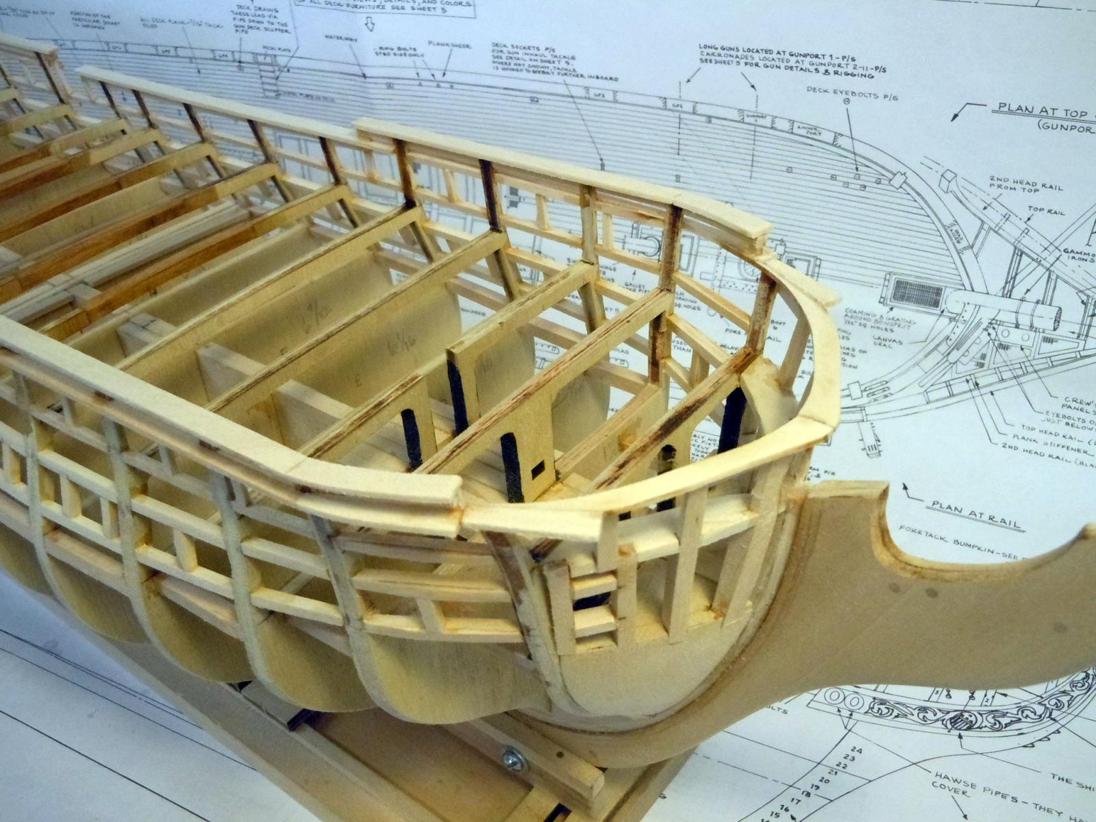
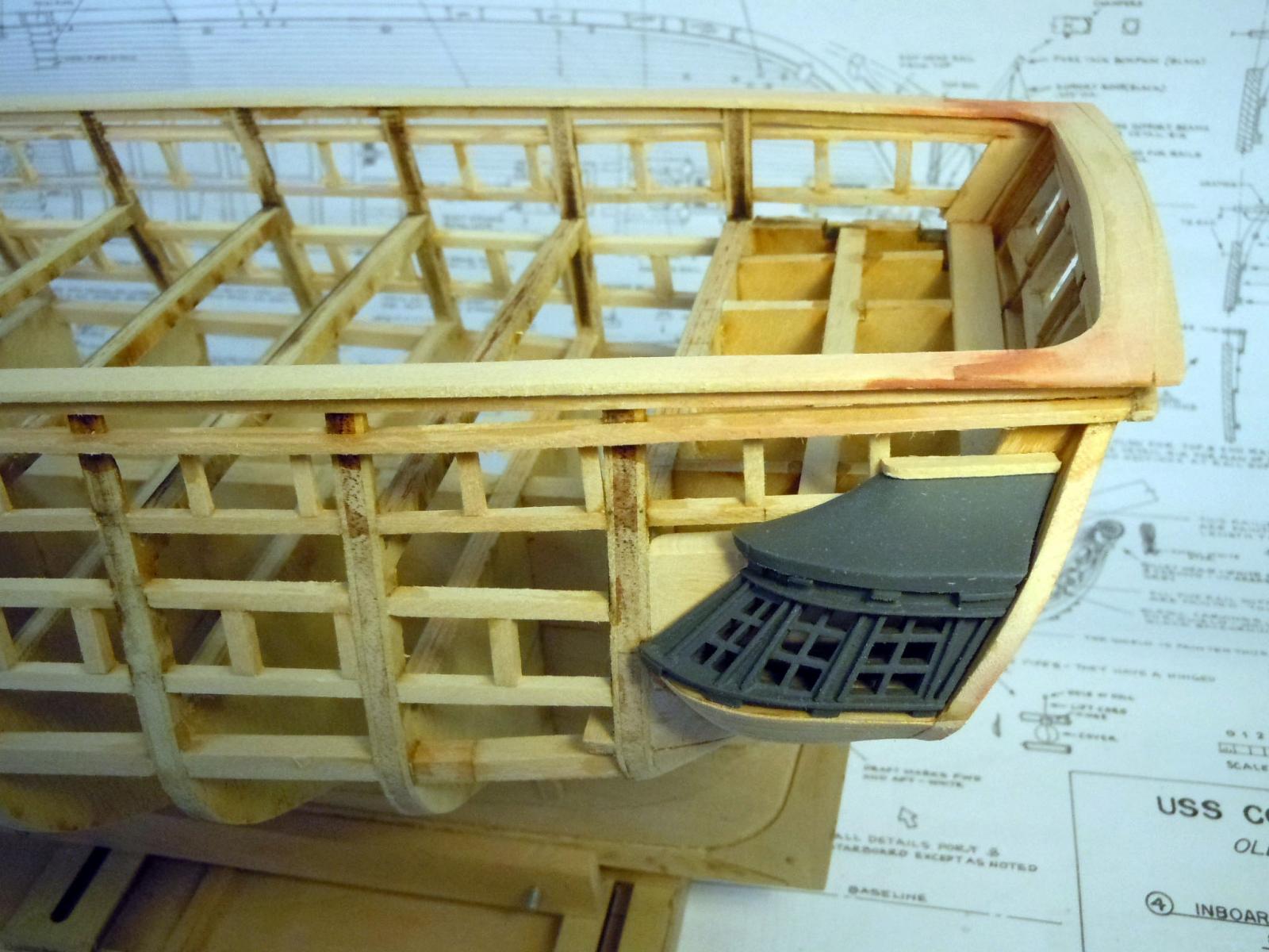
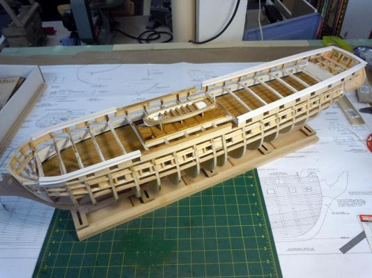
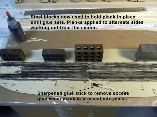
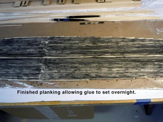
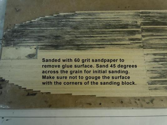
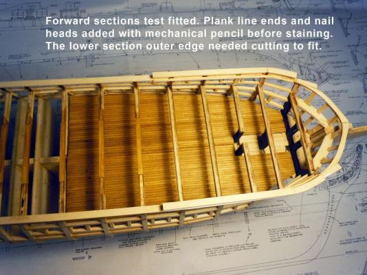
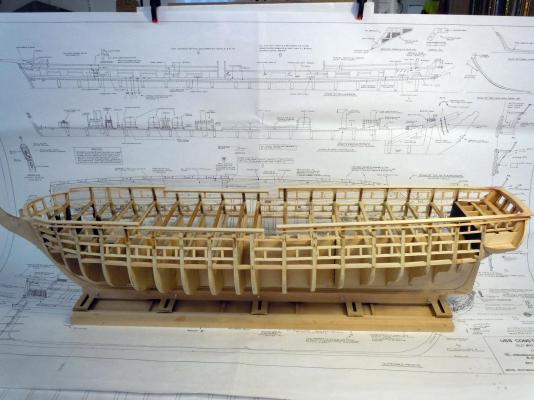
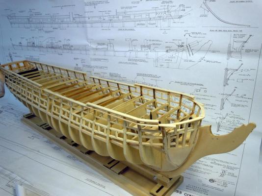
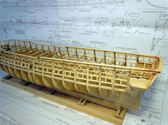
Back at ship modeling; I spent the long weekend helping my wife at her craft show merely as grunt labor. I finished up the modified main hatch grating and stained them. Here they are set in the main hatch framing. I also finished up the inner gundeck walls. I primed and painted the strips white before installing the planking. I could not resist setting the pinnace in it's stand upon the grating. I am still thinking on how to be able to lift the frame structure up to see the gundeck below; just another bridge to cross when the rigging is completed. After some pondering and thinking I decided it was not a time to add the cannons to the gundeck since the hull needs to be inverted to plank the hull. I started planking the hull per the instructions starting at the rails. One lesson I learned from the Niagara was to bevel the butt ends at 45 degrees for a positive interlock and also edge glued each plank to the adjacent one. This slows down the process a bit, but I work one side and then the other allowing glue to set. Here are a couple of views of the in progress planking. I also let the gunport planks dry overnight before trimming; so you will see some trimmed and others not. The planking on the bow required soaking before bending and edge forming clamped in place and allowed to dry in place, again overnight before gluing in place. Here is an overall view of where I am at so far. Now back to the planking which will be a slow process to get correct especially where the copper plating will go.


-
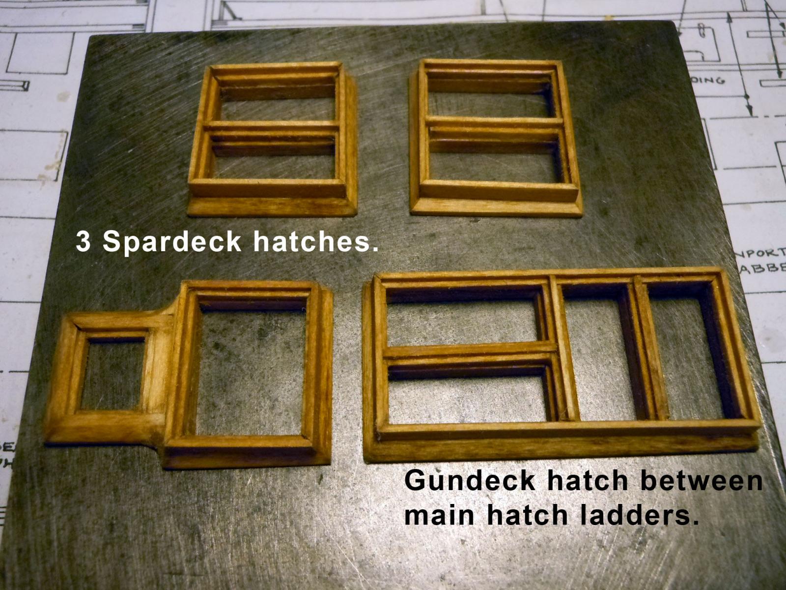
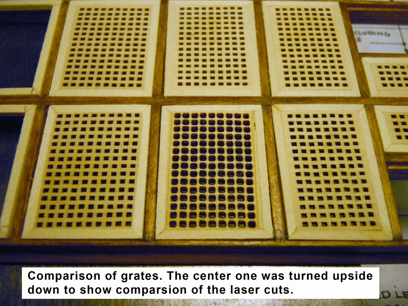
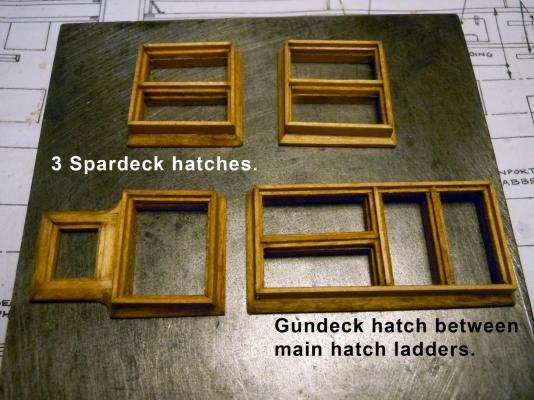
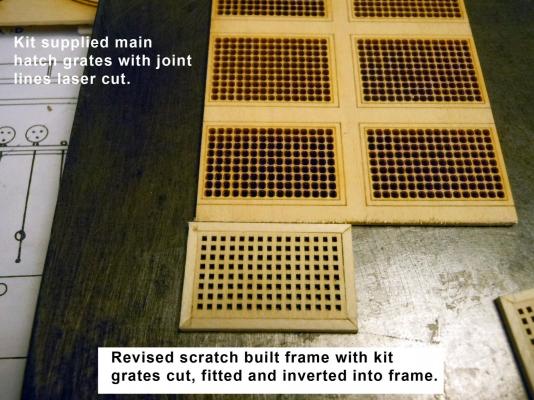
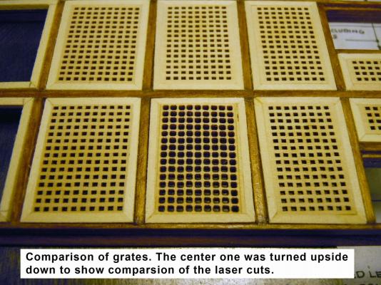
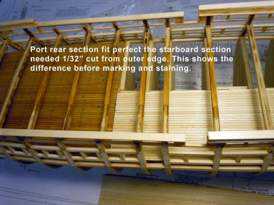
A quick "in progress" update on hatches and grates and to clarify an issue on laser cut parts. As a kit designer for both Model Expo and Fine Art Models I have to explain common errors on the ship kits I have built so far. Somewhere in the development process when the laser files were created they did not take into the fact that certain opposing common parts need to be mirror imaged and that the finished dimension of the cut part is on the bottom surface of the wood sheet not the topside. The size of the parts are impacted by the thickness of the wood sheet being cut. Here are the hatches fabricated so far waiting for grates. I glued these parts together on the steel block since the wood glue does not stick to the residual oil film on the surface of the block. Once tacked off they are set aside. Here are pictures of the main hatch. The kit part has the frame lines burned in around the grate openings which are to be 1/32" square, per the plans. So I fabricated the grate frames using 1/16" square strips on the steel block and set into the frame location to set once tacked off. I then sanded the char from the bottom surface of the sheet with the grates and very carefully sawed and sanded to size the inverted grate into the frame with the crisp grate openings showing. The difference is quite striking and only tells me that there is a great lack of understanding of designing laser cut parts in these kits. Here are a couple of pictures showing the difference. Now back to more hatches and grates. I just wanted to share the above while I was thinking about it.
-
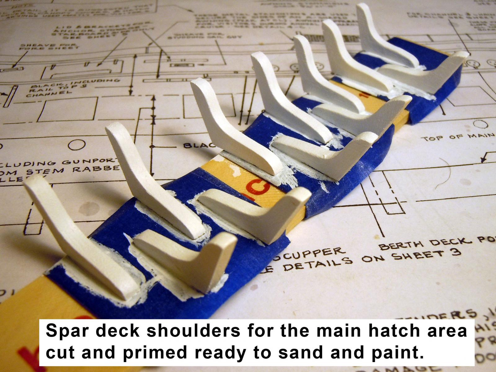
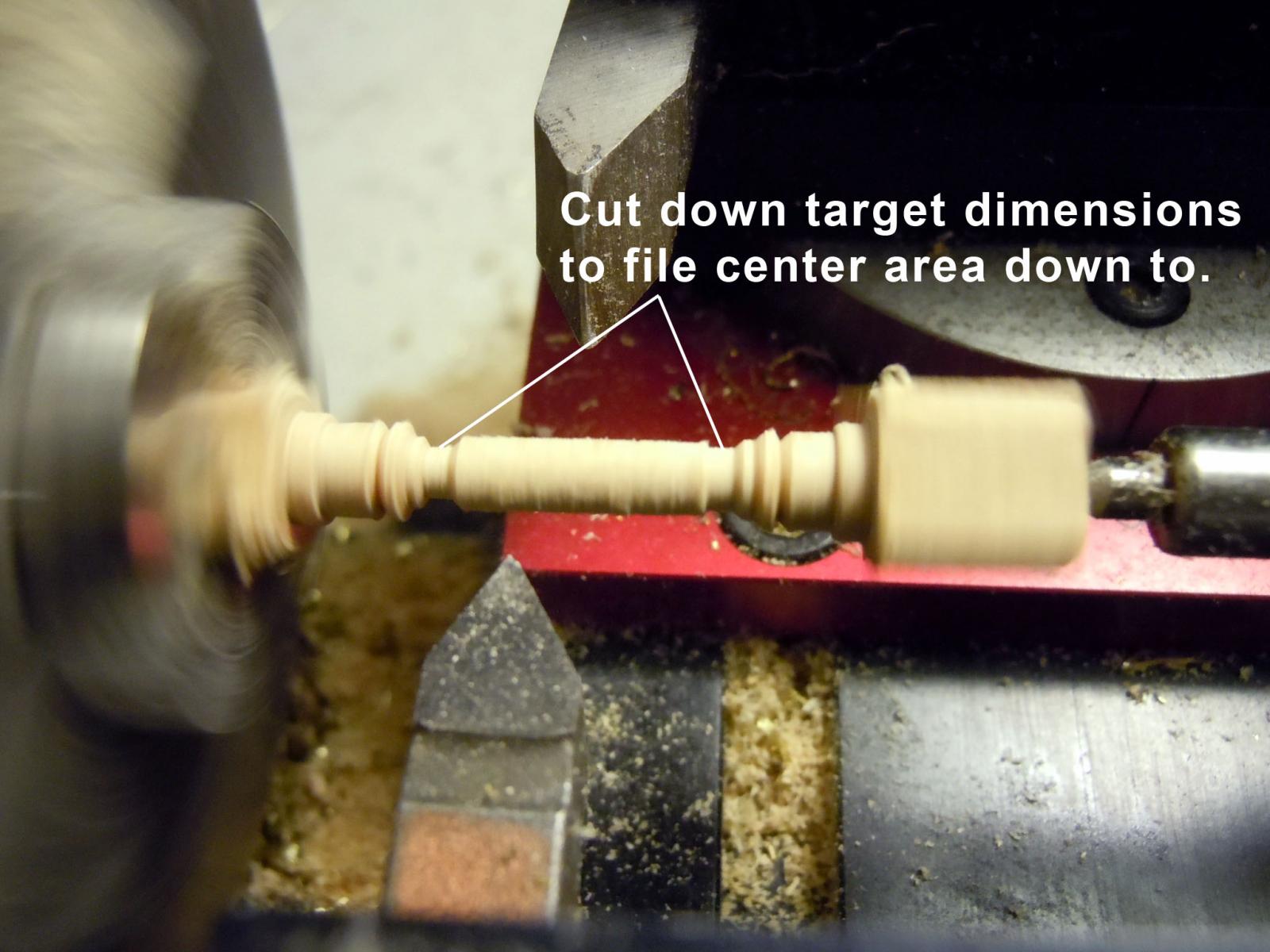
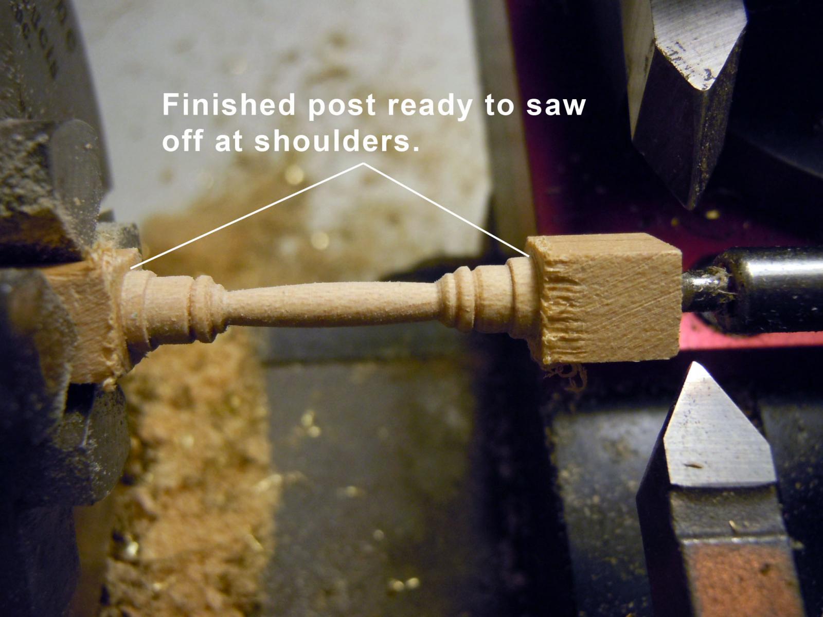
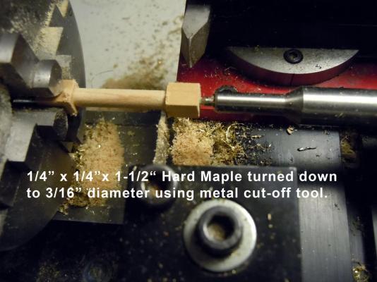
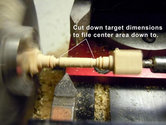
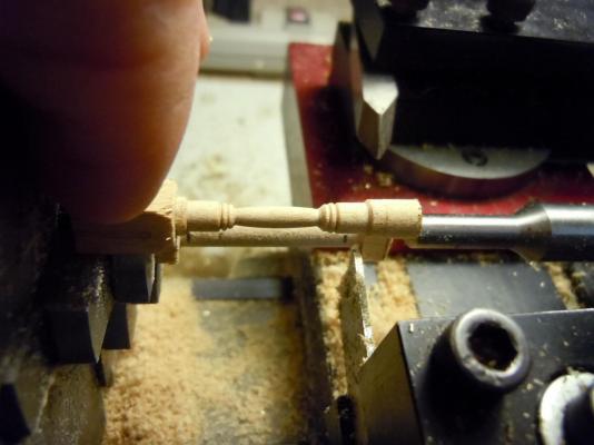
I cut and sawed the spar deck shoulders for the cargo areaand then primed and painted them. The jeweler saw made short work of cutting them. Next I glued them in place. If I had to do this again I would install them before adding the side wall to the gundeck. But since the bulkheads are not in the correct positions to complete the framing I will just do the shoulders. Here they are in place. Next I turned the three main hatch deck supports on the lathe using hard maple. Hard maple holds detail much better than basswood when turned. Here is a sequence showing the process. Here I used a triangle needle file to form the bow with the reference cuts to the shoulder. This is small enough for the file to work with great results. Once one was done it was easy enough to transfer reference marks by indexing and aligning the square end into the chuck next to the one to be cut. Now back to making more hatches and ladders for both the gundeck and spar deck based on what can be seen through the main hatch opening and others.


-
Great build! I just reviewed it from the beginning and very impressive work. I am looking forward to seeing your final paint scheme. Keep up the great work.
-
George, I am not familiar with any ; but I am sure if you contact the Weller Tech support they may be able to provide the information that you need or point you in the right direction.
-
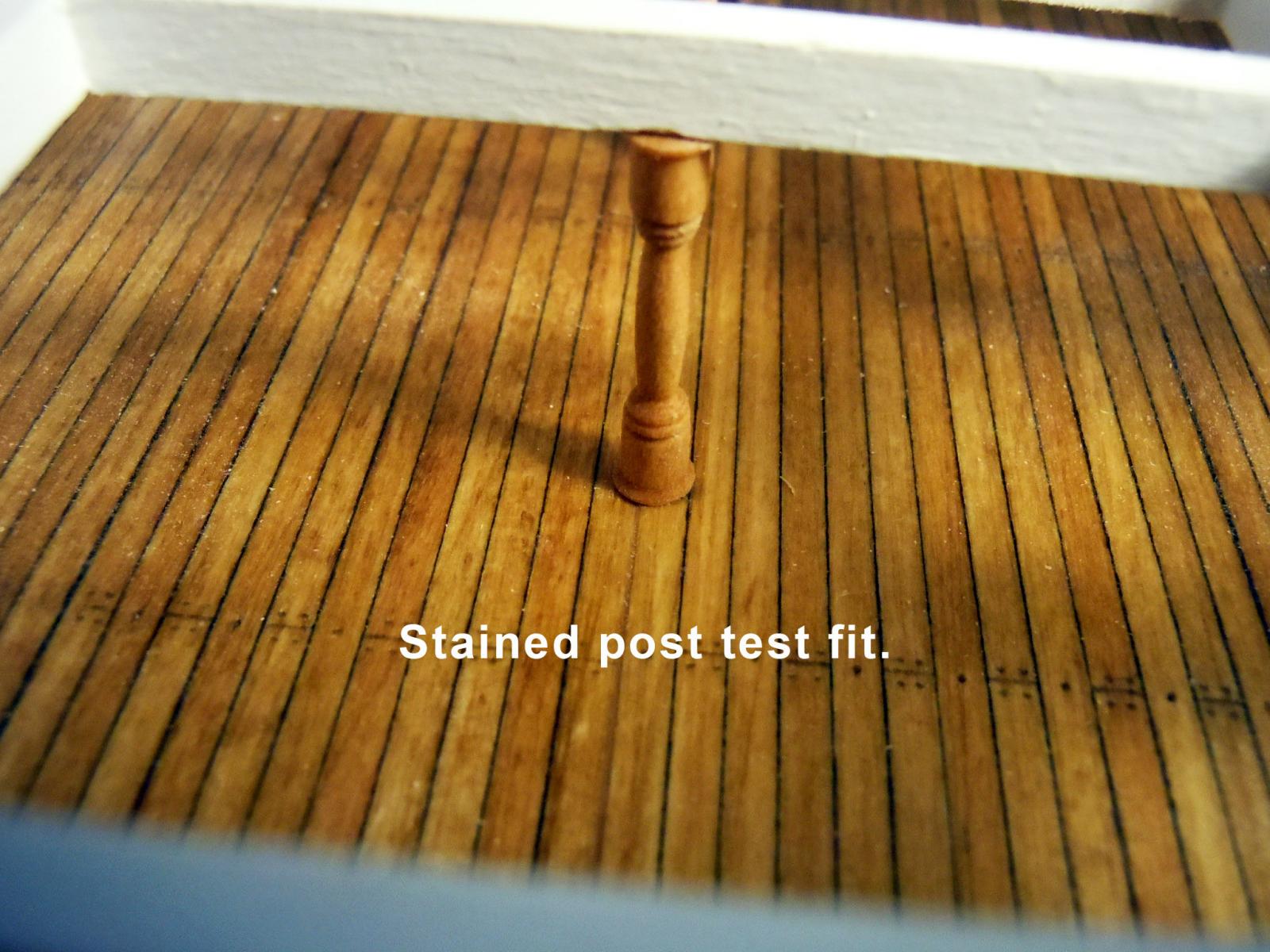
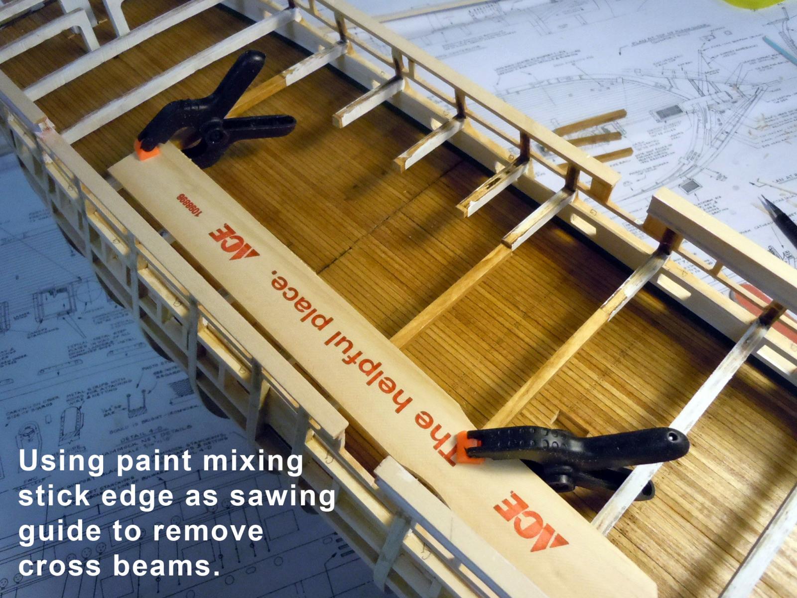
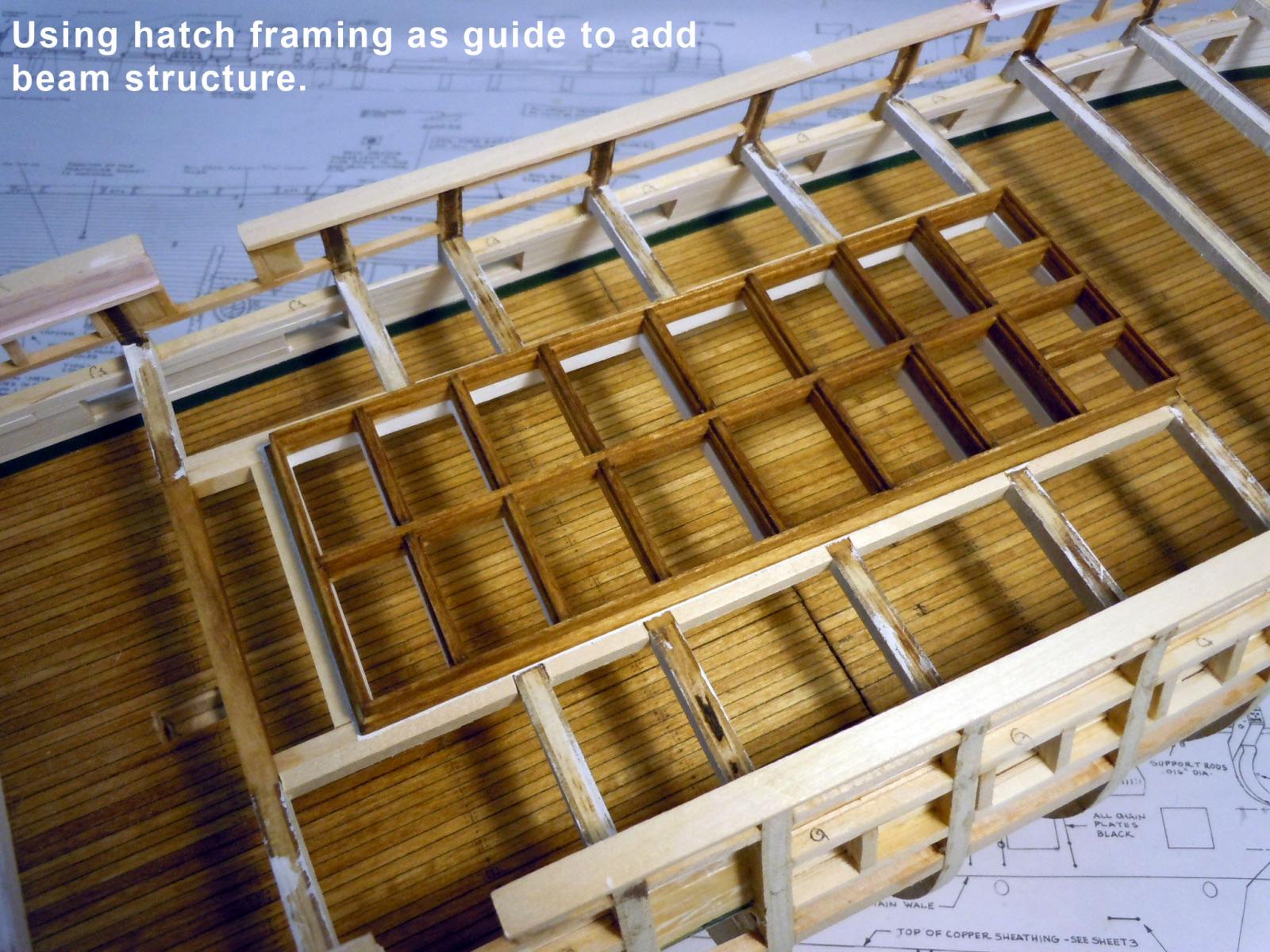
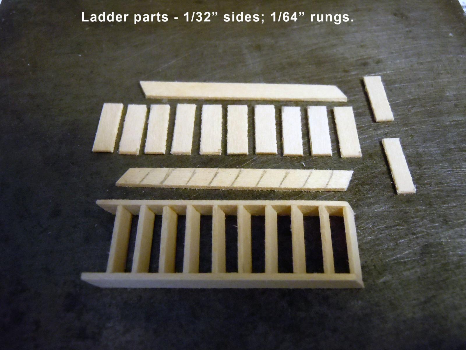
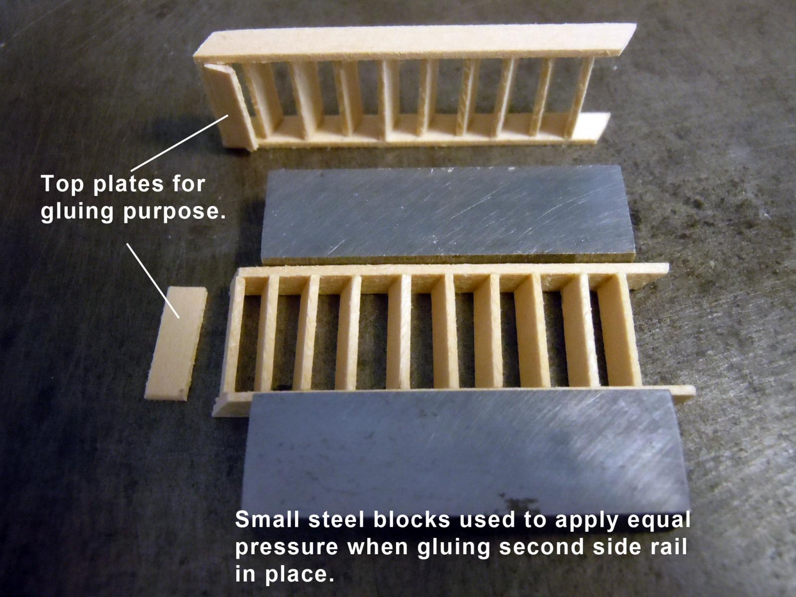
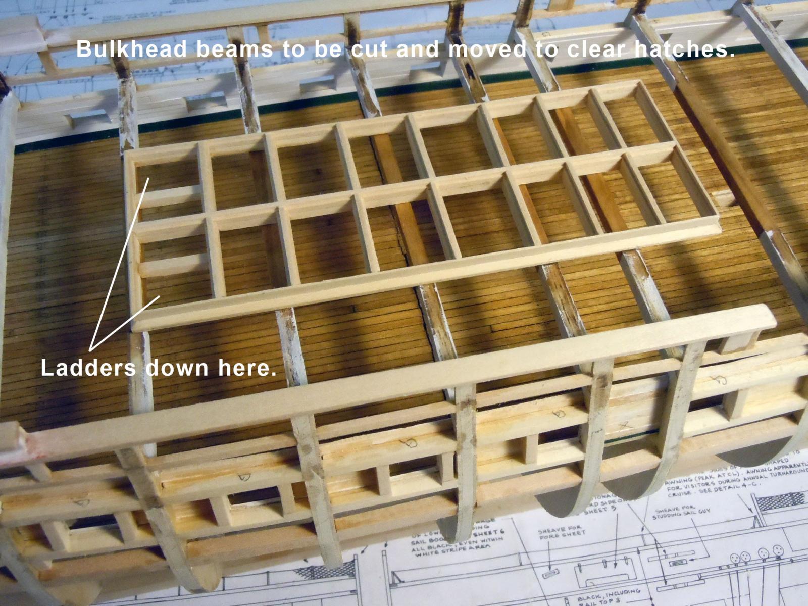
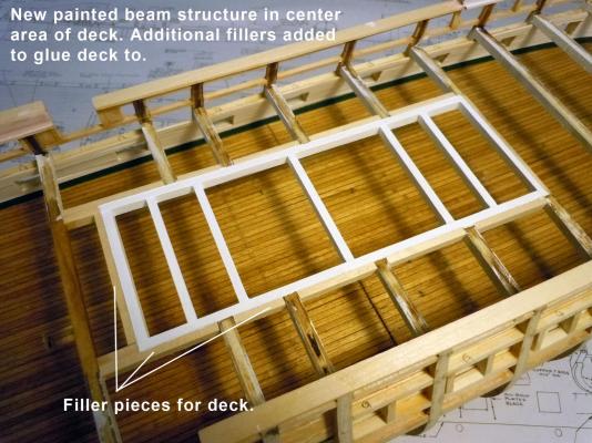
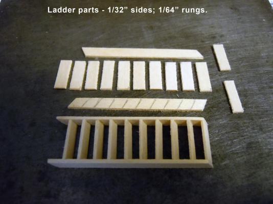
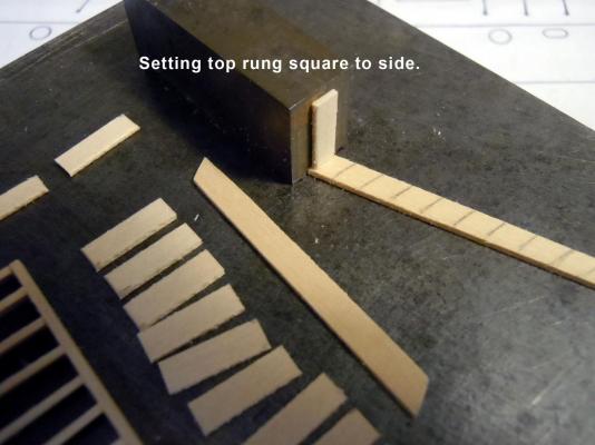
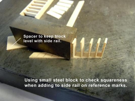
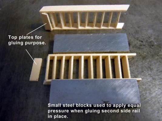
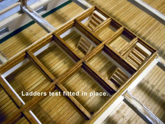
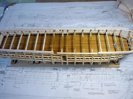
I finished up the framing structure for the grates and then used it in position to mark the deck beams for removal. Once marked I clamped a paint stick as a guide for the mini saw blade. I rubbed the saw blade side with candle wax as a lubricant to reduce grabbing when sawing. First I added the perimeter framing using 3/16" x 1/4" wood stock. Once the perimeter was set the cross beams were added one at a time using the grate structure as a guide for correct placement. This shows the added beams in place and painted. I also added fillers around the perimeter to be able to glue the deck to when needed and left them unpainted for better adhesion. Next I built the two ladders for the main hatch. After checking around at numerous pictures I counted eight rungs visible from the gun deck to the underside of the spar deck beams and that the top of the ladders ended at the grate stops. Next I used "Mr. Geometry" to determine the spacing of the rungs and marked the locations on one of the side rails. Here are the ladder components. First I added the top rung and used a steel block to square up until the glue set. I then added each of the rungs working my way down the ladder. Glue was carefully added to the ends of the rungs and the second side rail added aligning to the top rung and carefully pressed together using small steel blocks for equal pressure and let the glue set. Here are the two ladders test fitted in place. Now to stain the ladders and fiquire out the post hand rails.


-
Tom, I see your test sailcloth after drying was fairly wrinkled. Try ironing the sailcloth with spray starch to smooth out the fabric and then brush on the 50/50 mixture. Then once dry on low heat on the iron smooth again. Looking great keep up the great work you are doing!
- 1,354 replies
-
- 2
-

-
- constitution
- model shipways
- (and 1 more)
-
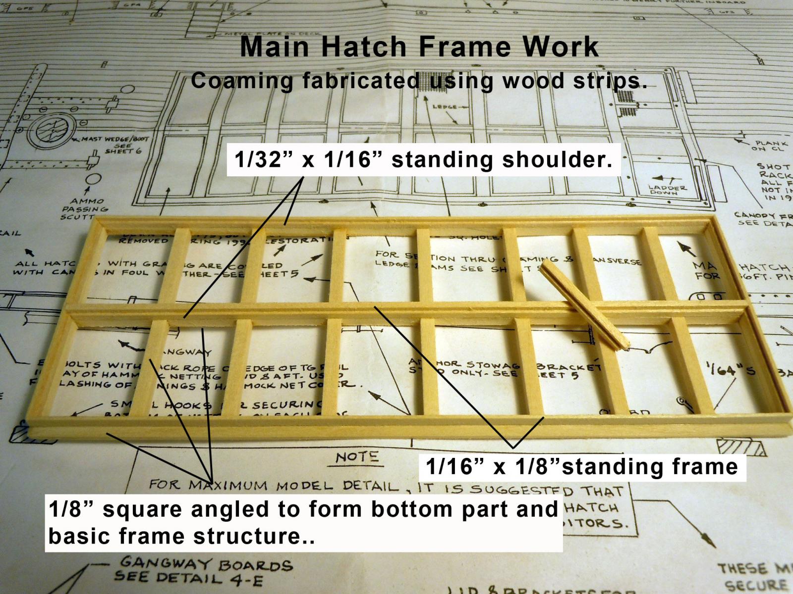
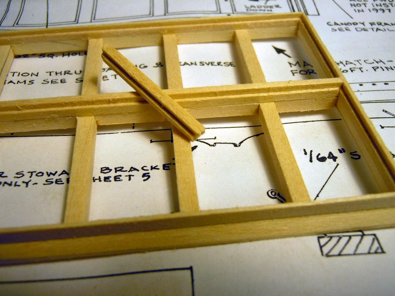
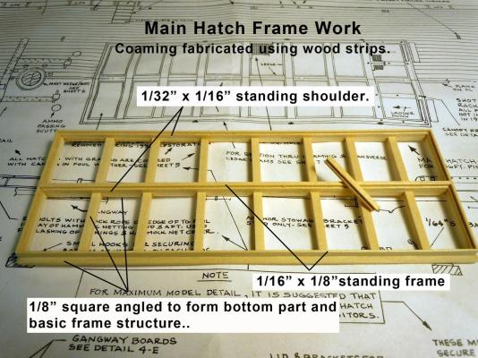
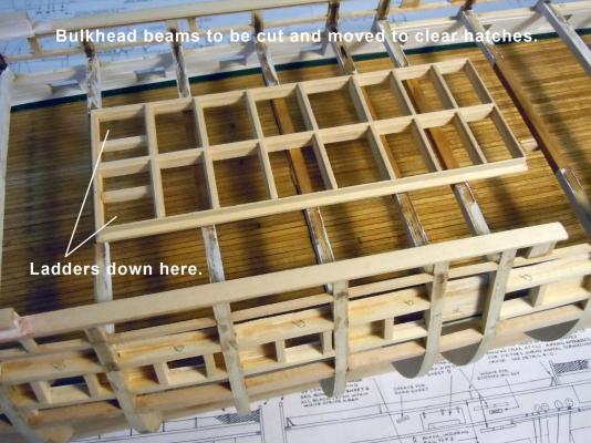
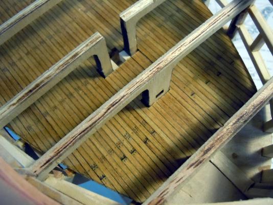
Tom, not sure if that will ever happen especially when I create more work for myself. I finished off the gundeck side walls and cut and trimmed all the gun ports for now. I have seen two color versions of the side walls, one green and one white. I assume both are correct for different time periods. I am favoring the white to match the gun strip down the road unless informed otherwise. I then moved onto the main hatch and fabricated the frame structure using various sized wood strips. I then set it on the hull framework measured twice using the mast center points and saw that beams went through grate openings. I checked various images that I could find and the walk around clearly shows the beams under the frame work of the main hatch. I understand that the model kit did not intend the gundeck to be finished out so I am sure this structure was not considered. Here is the main hatch started Here is a close up detail while in progress. Here is the main hatch finished up set in place and ready to be stained for the bright finish. Now back to doing some critical surgery on the hull beams.

-
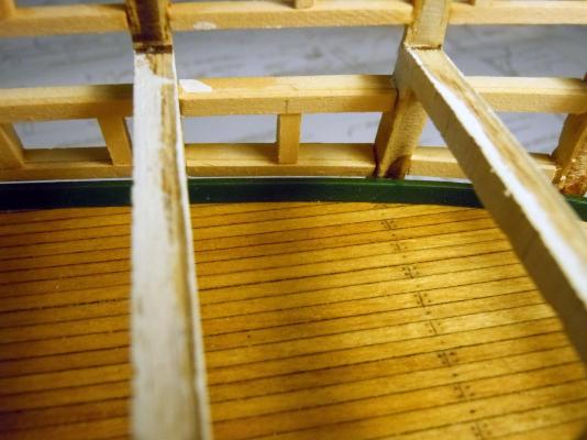
I filled in the decking area that will be below the bowsprit since it will be partially seen through the gunport. While waiting for the gundeck planking glue to set I moved on to the waterways and shaped them taking the deck thickness into consideration and then painted them green prior to installing them in place. I started with 1/8" x 1/8" x 24" wood strips and cut the angle using reference lines on the sides with my mini plane. Once the angle was trimmed to satisfaction I then cut off the bottom thickness to the edge of the angle; this was the thickness of the deck. The boards (3) were installed with the 24" length butted to the stern wall with a 45 degree angle cut on the bow end. This provided an entrapment for the forward bent piece to be installed. The forward bow piece was carefully and slowly wetted on the back unpainted sides to allow bending, care is needed not to get too wet or the paint can be affected. I did one at a time wetting and carefully bending to the point I could dry fit and cut the ends one engaging the 45 degree angle and the bow end butted to the wall. This shows an overall so far with the waterways in place. Next I turned to the inner walls and quickly realized that they had to be thickened by 1/32" since the framing was done with 3/32" square strips rather than 1/8" square strips. Not hard to do just time consuming. I then primed, sanded and painted the inner wall strips 1/32" x 1/8" x 24" leftover stock from the Niagara. I decided to do enough for both the gundeck and spar deck. Here is the start of the inner walls thanks to Tom's great walk-around link. When both sides are done I will be able to look through the gun ports to decide how much detail to add other than the cargo loading area. Now back to adding the inner wall strips and cutting gun ports as I go.
-
Nigel, outstanding carvings they look fantastic!
- 270 replies
-
- 3
-
-
- red dragon
- artesania latina
- (and 1 more)
-
Tom, on your sail canvas; try a mixture of 50/50 white glue and water then soak the canvas with a brush and allow to dry on a piece of wax paper. Then punch it and you will get a cleaner cut. Keep up the great work you are doing, I am slowly following in your footsteps with my build.
- 1,354 replies
-
- 3
-
-
- constitution
- model shipways
- (and 1 more)
-
Bob, thanks every picture helps! Check out the walk around link that Tom posted it has everything I need to know. Thanks again!
-
Tom, Thank you very much for that link and your timing is perfect because I have started the waterways and was wondering what color they should be. Thanks you again! That is what is great about this site is the sharing of information.
-
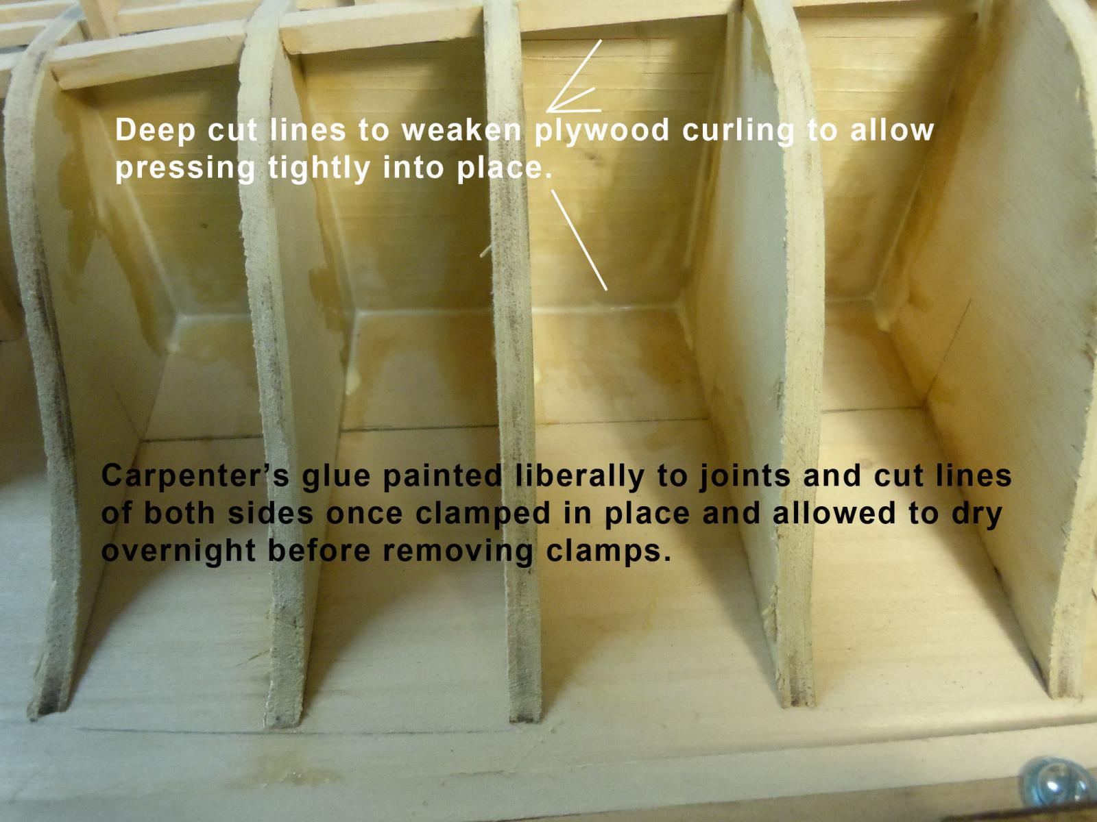
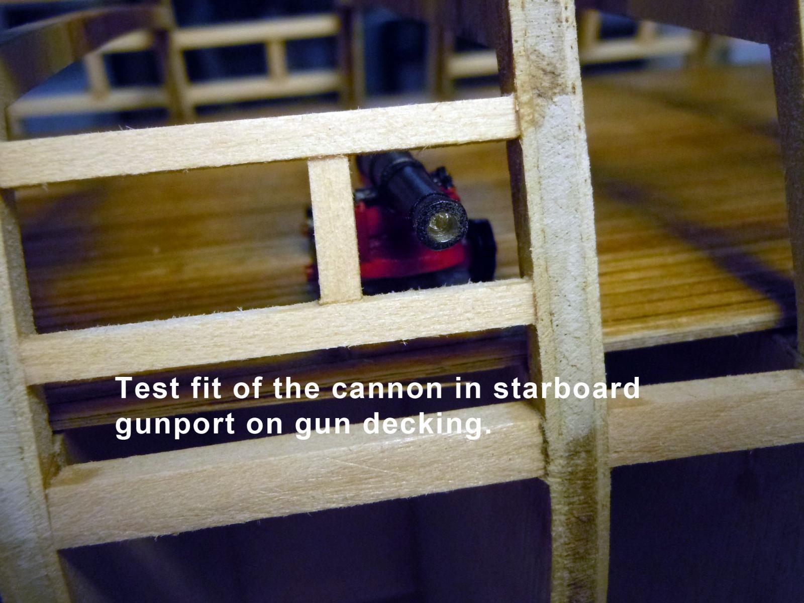
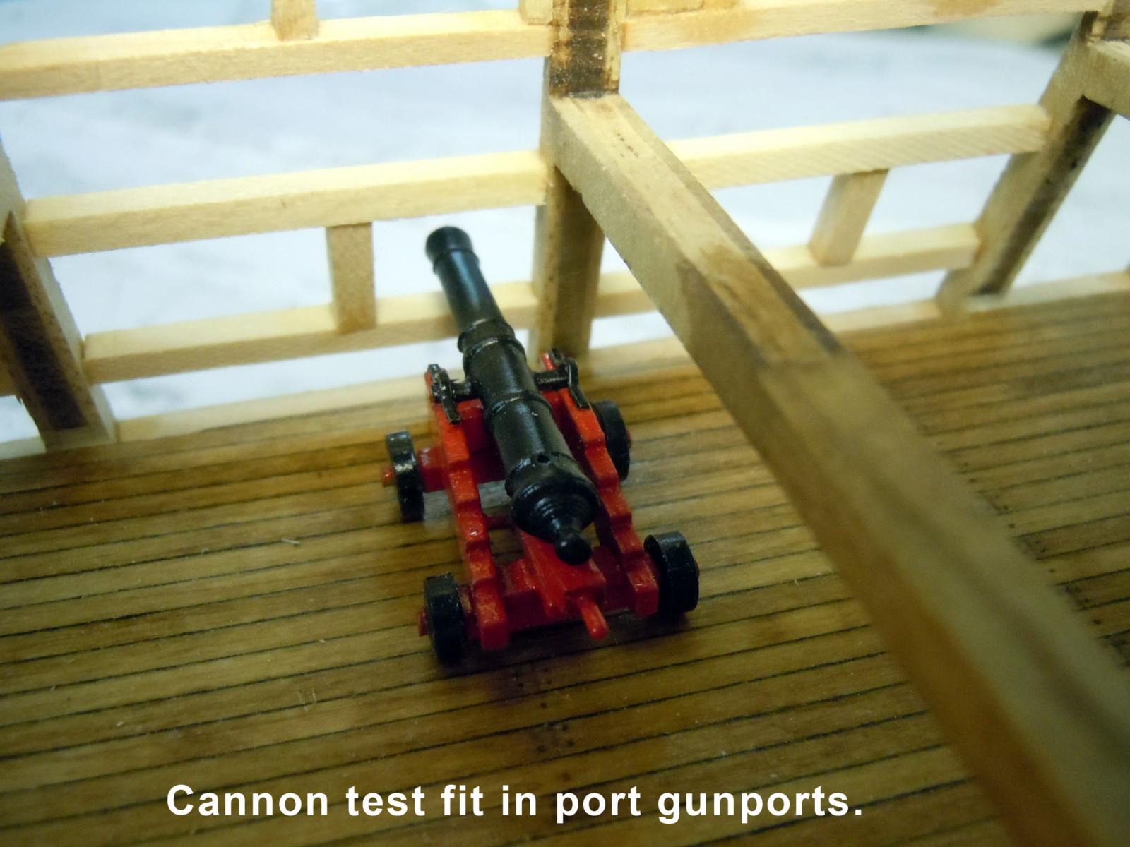
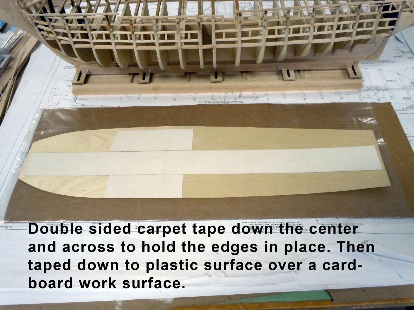
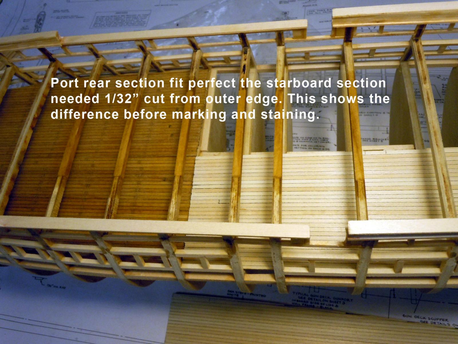
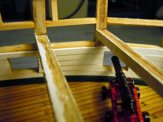
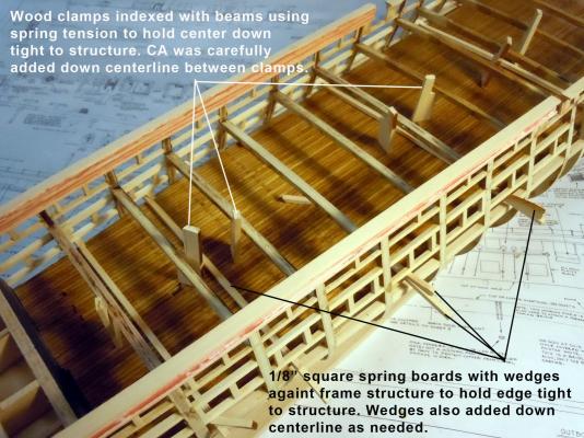
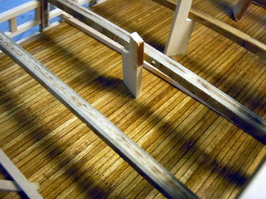
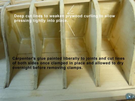
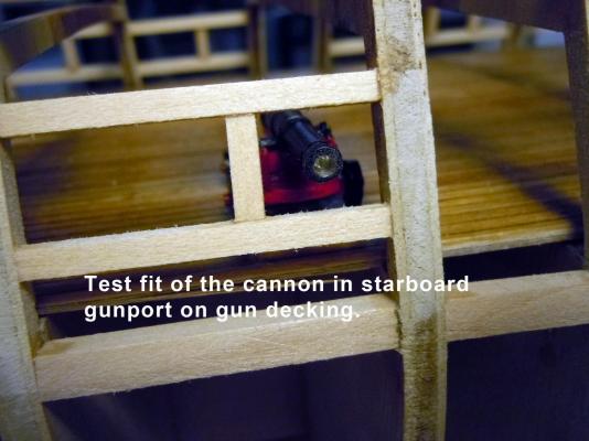
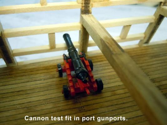
Well the experiment partially worked. The 1/64" plywood even though weighted down when the decking was glued to it still curled enough to not fit tight against the bulkhead structure. I had to deep cut the plywood side at 1/8" intervals to weaken it enough to bend into place. Here is a series showing the process I used. The forward sections were clamped and glued down first and then the rear sections. Next time no plywood and I will use fabric instead. The glue was allowed to set overnight for both setups for and aft. Then once the glue was set and clamps removed the true test was the fitting and checking of the cannon in all the gunports. I had a big smile they all fit dead center. Now to add the inner walls and structure which will be painted all white. Does anyone have an image of the back wall with the doors to the cabin areas? I have not found a picture yet in all my looking on the net. I now have to decide how much detail to add to the gundeck.
-
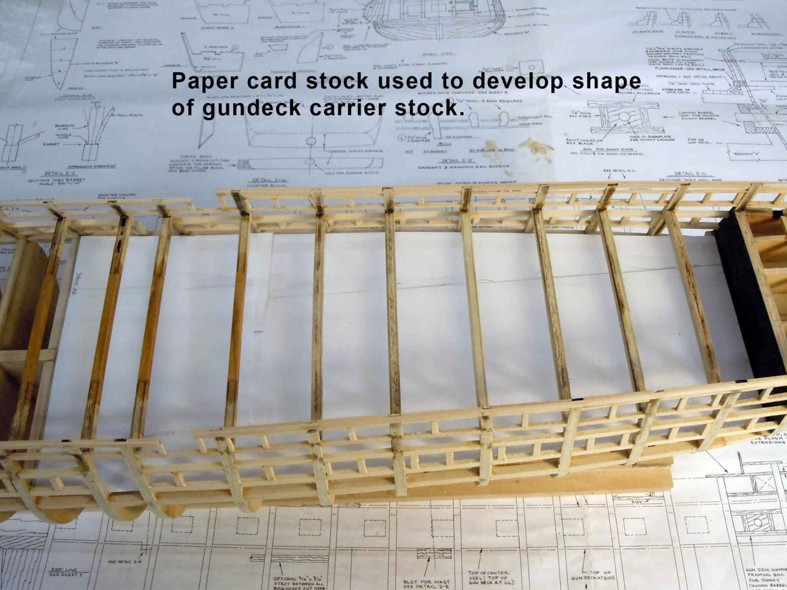
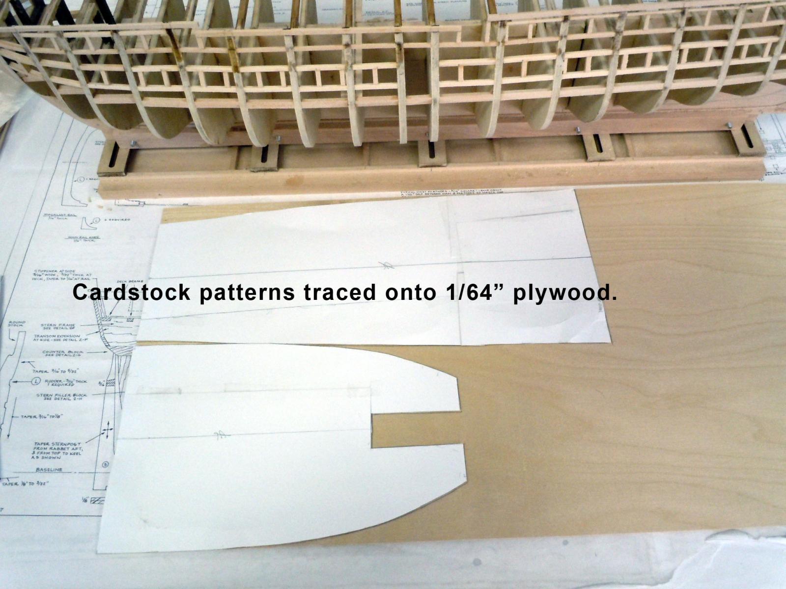
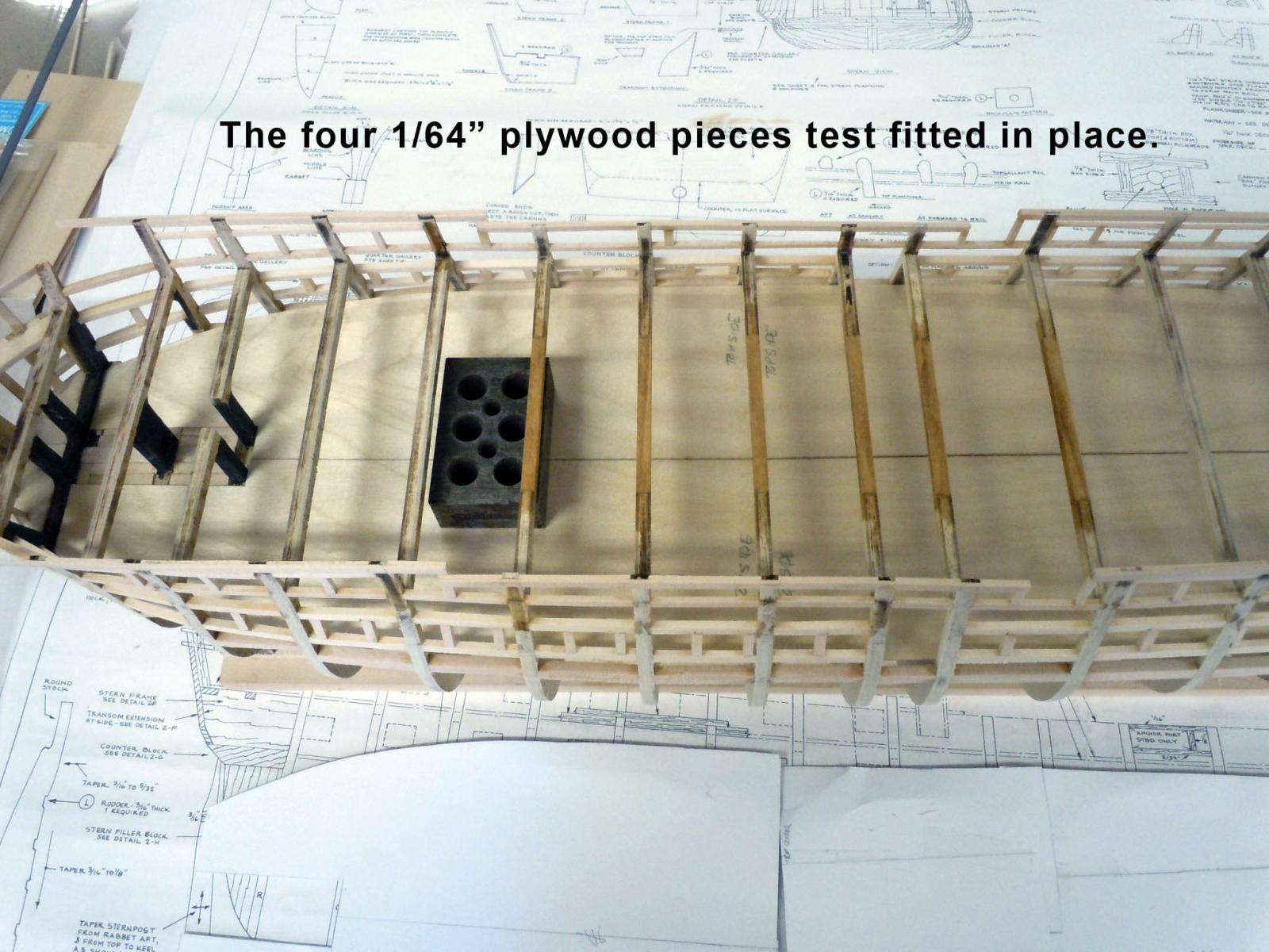
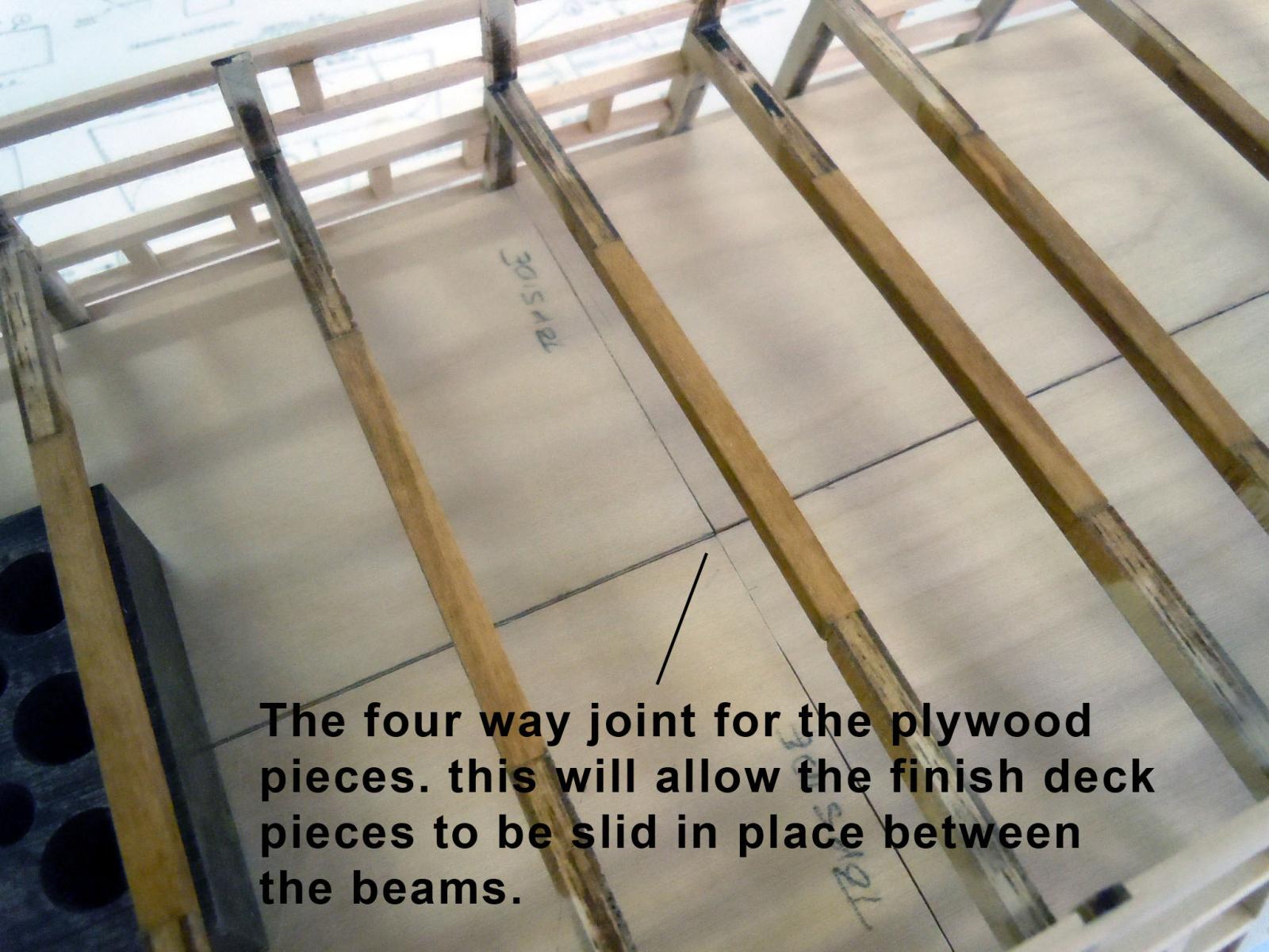
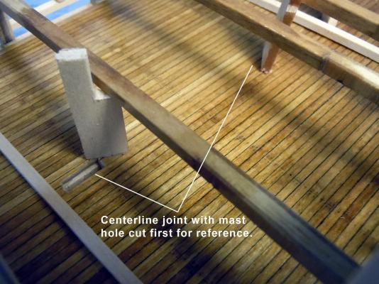
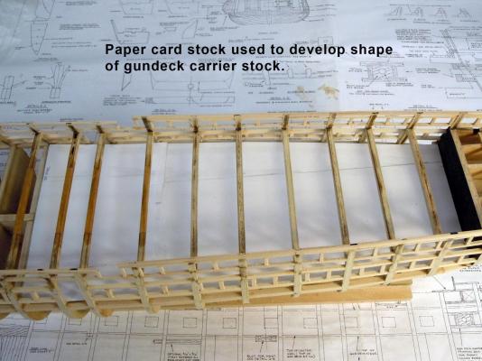
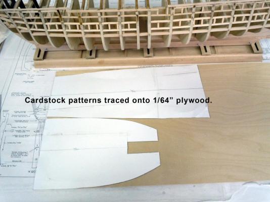
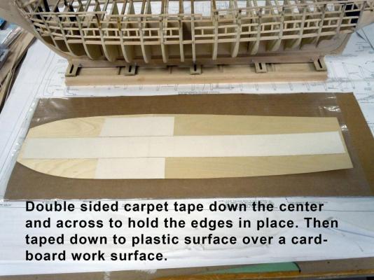
I started with card stock patterns of the gun deck. I have added comments to the pictures to be self explanatory. I hope all had a great holiday season. We had the best gift of all; our son and daughter-in-law are having twins in June.


-
Tim, none of my individual photos is over 2MB or even 1 MB, however I was trying to post a sequence of 12 photos to show the deck build. I even tried only posting only half with no success. Will keep trying when I get a break in building. Thanks. Tim, just went back and checked all images sizes, the largest one is the one above at 541K.
-
Working on the gundeck but having trouble posting updates so this is a test with one image. Hope this works. Admin----Well it worked with one; is there a size limit on posting?

-
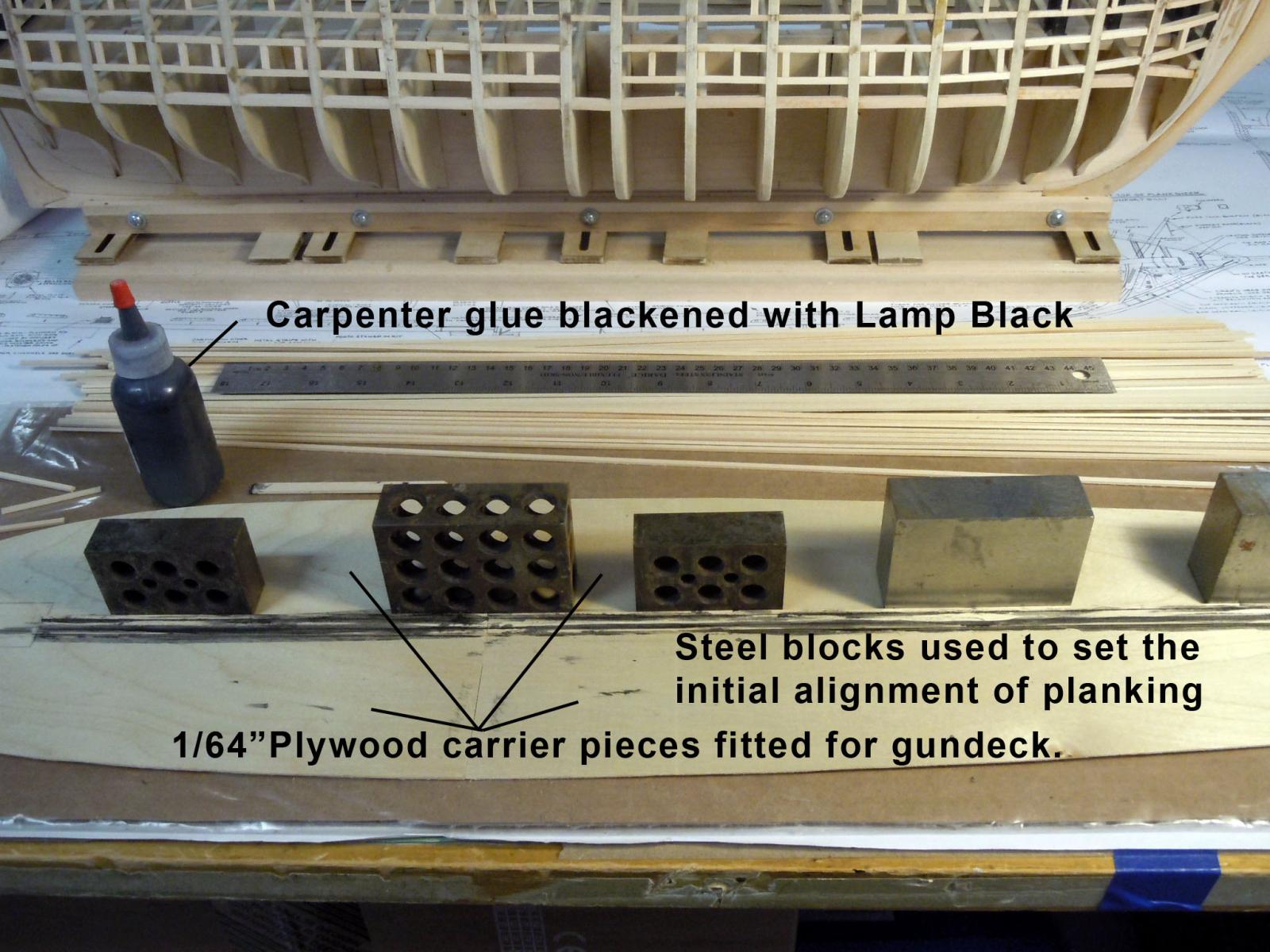
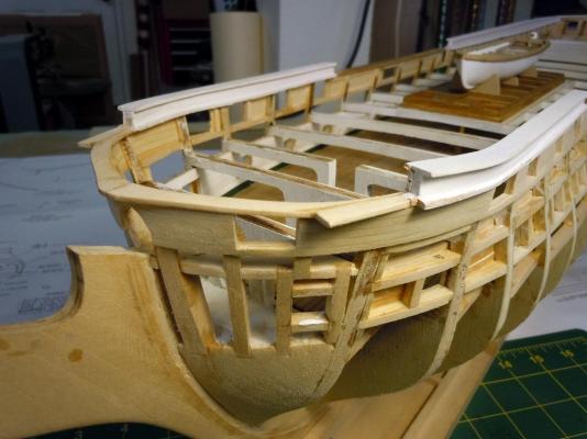
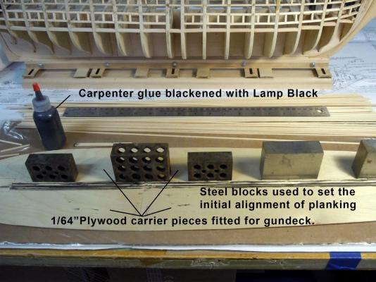
I spent some time installing the main rails and topgallent rail. This will strengthen the top structure for when I turn the hull upside down to add the hull planking. Here are several views of them in place. I just had to do a little filling at the rear joints where the rail met the laser cut part. I also had to thicken the laser cut part on the inside to allow overlap with the inner wall planks. The exterior transom planking is already in place. My deck planks arrived today so I will now start gluing the deck planks for the gun deck. These will be glued to four 1/32" plywood carriers that have already been fitted to the gundeck shape. I will also use black glue like I did on the Niagara for the joint caulking lines.


-
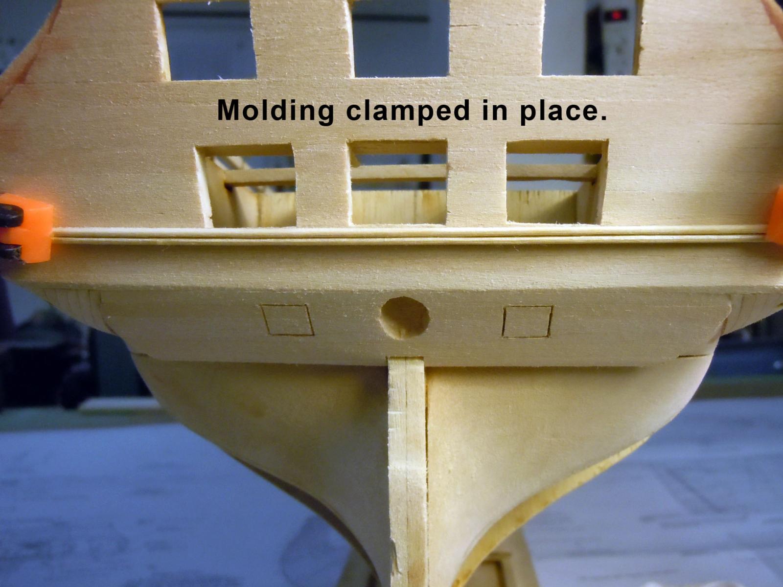
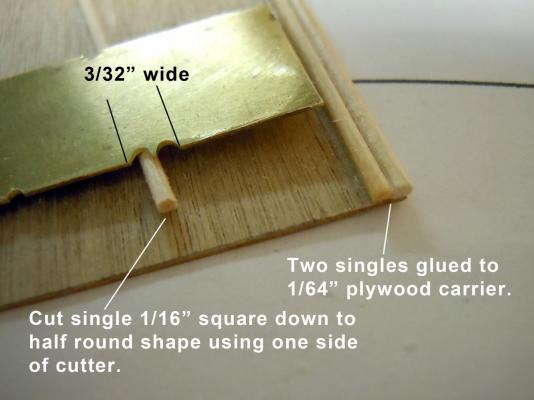
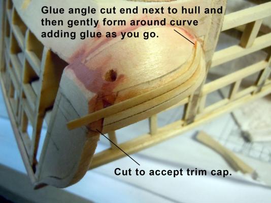
George thanks for the video link, very informative. I checked around looking for how other builds handled the trim molding and saw reference to polystyrene. Unless painted polystyrene will yellow over time due to UV exposure resulting in a light almond color. I then filed two half rounds in a piece of .020" brass sheet to a width of 3/32" wide. I then carefully and gently cut a 1/16" square strip down to a half round shape cutting a short section at a time on a steel block. Once two lengths were cut I then glued one onto 1/64" plywood as a carrier on an edge or a scored straight line. I then glued the second strip butted up against the first and allowed the CA to set. Then using the double section of the cutter I carefully cleaned the center joint again on the steel block. The key to clean cutting is determining which way the grain goes to allow easy cutting. If you are chattering of chunking the wood you are cutting the wrong direction; turn the strip end for end. Here is the finished molding clamped in place and is ready for priming and painting later once the transom is painted black. Now to cut a couple of more lengths for the transom and side galleries. For those not wishing to make a cutter Northeastern Scale Lumber offers a 3/32" double bead, product code 332DBLBEAD at 24" long for a $1.45. This is a great site for purchasing various types of scale lumber including ready made deck sheets 3" wide x 24" long.

-
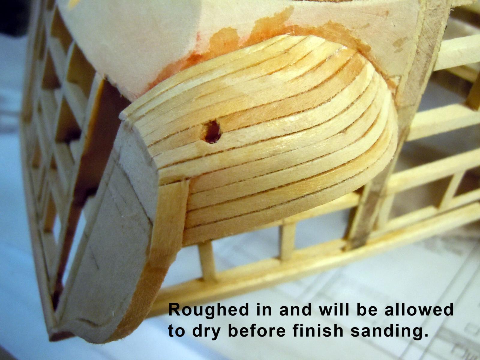
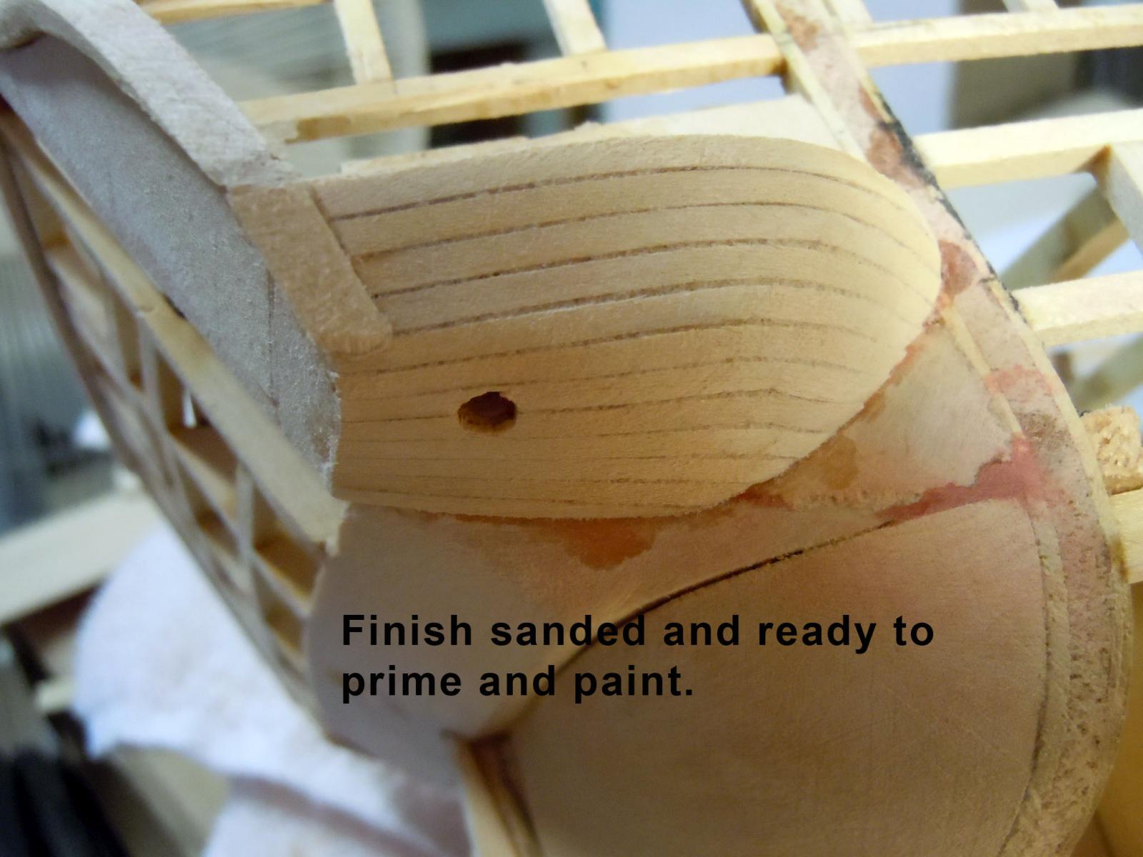
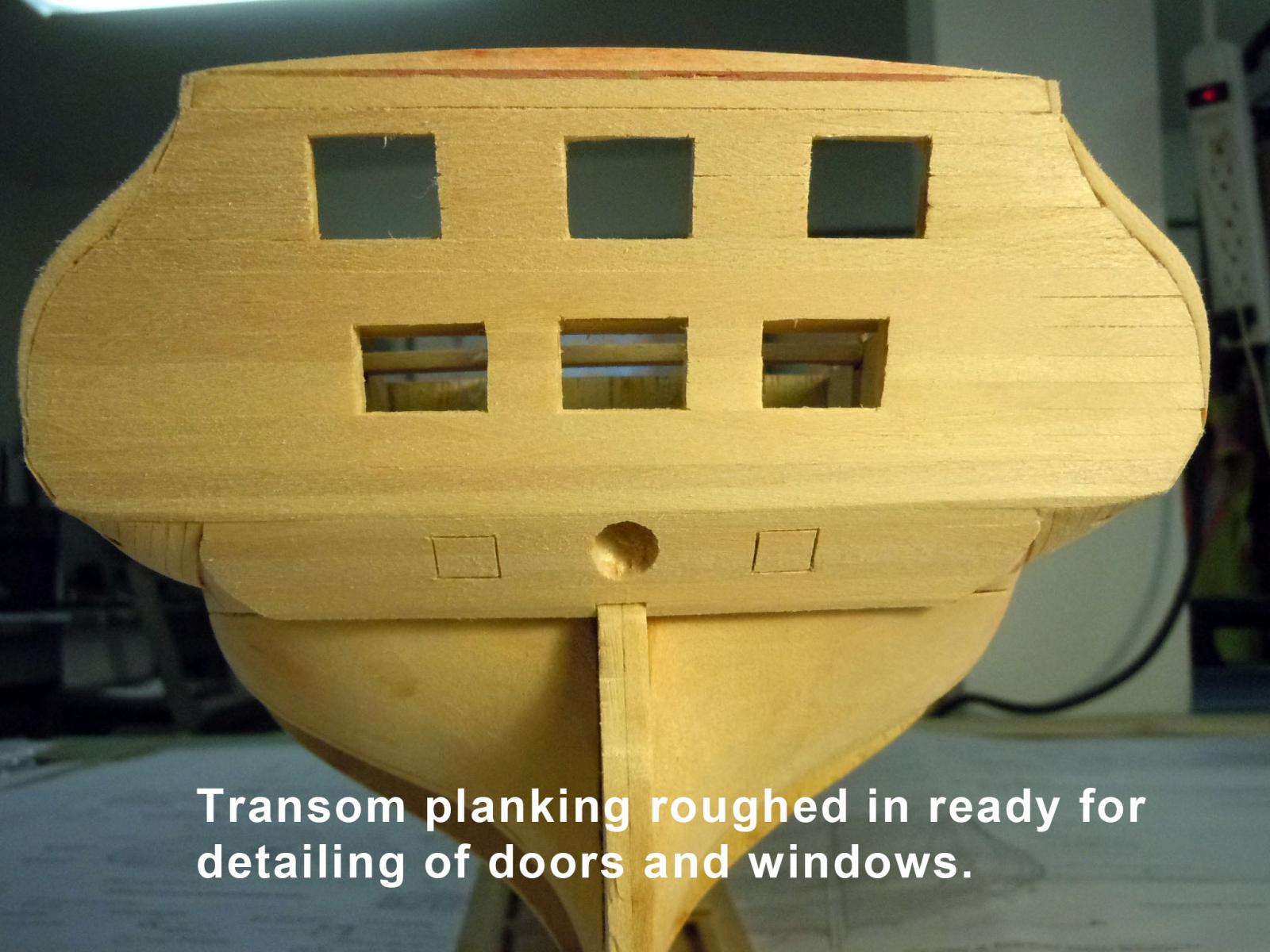
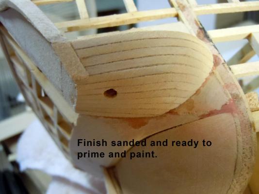
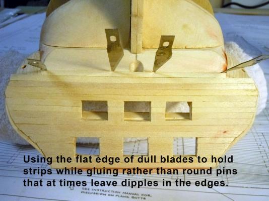
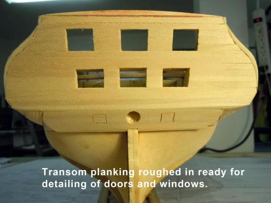
Captain Steve and Tom, thank you for your advice I will proceed with the three window setup. While waiting I planked the bottom of the galleries using Midwest #3008 basswood strips. At .0208" they were very pliable once soaked in water. Here is the start keeping in mind to trim to allow for the cap plate. Here they are roughed in. I used CA for this process on the wet strips which held right away. Once completely dry they were then sanded. The hole is for the head. After deciding to go the three window direction I then proceeded planking the transom after adding the window structure. Here is a tip that I use occasionally; I use the flat side of the tip of a blade to hold strips rather than pins which sometimes leave dimples in the edges, especially in wet strips. Here is the transom completed with the planking ready to move on to other details like window trim and gap filling. Merry Christmas to all!


-
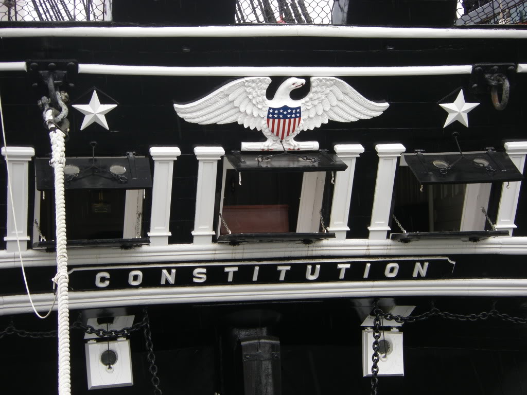
Captain Steve thanks for your help and images! Do you know if the five window really existed or was it just in a painting? I see the six and the five with the same year 1812 in paintings. I have found absolutely nothing on the 5 or 6 window configurations with enough detail to build. I have found some great photos of the current three window and may just end up sticking with it since it offers the best reference details. Again thanks for your help! Have a Merry Christmas and a Happy New Year! Ken Here is a great photo showing the detail of the trim work.

-
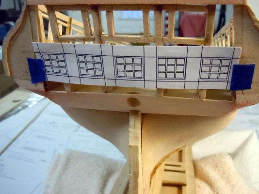
Tom, I did a quick sketch using my other CAD system (Corel CAD) with the same configuration of three panes up and across and the bottoms aligned with the gallery windows and the same height. I do not think this layout is correct because these windows need to open while the Gallery windows do not. I looked at George's photos and the gray one from 1914 shows only two pane windows that do open. I do not have a picture of what they should be and am hoping Captain Steve can supply an image from that book he has like he did for the galleries. Here is the CAD sketch of the five window layout. Captain Steve please help if you can?
-
George, thank you very much for those pictures. I see I have a few minor adjustments to make on the galleries. Also good to see my assumption on the bottom and tops of the windows are parallel to each other. I knew there was molding and now I know what they should be. Merry Christmas and Happy new Year to you and yours as well!