xken
-
Posts
841 -
Joined
-
Last visited
Content Type
Profiles
Forums
Gallery
Events
Everything posted by xken
-
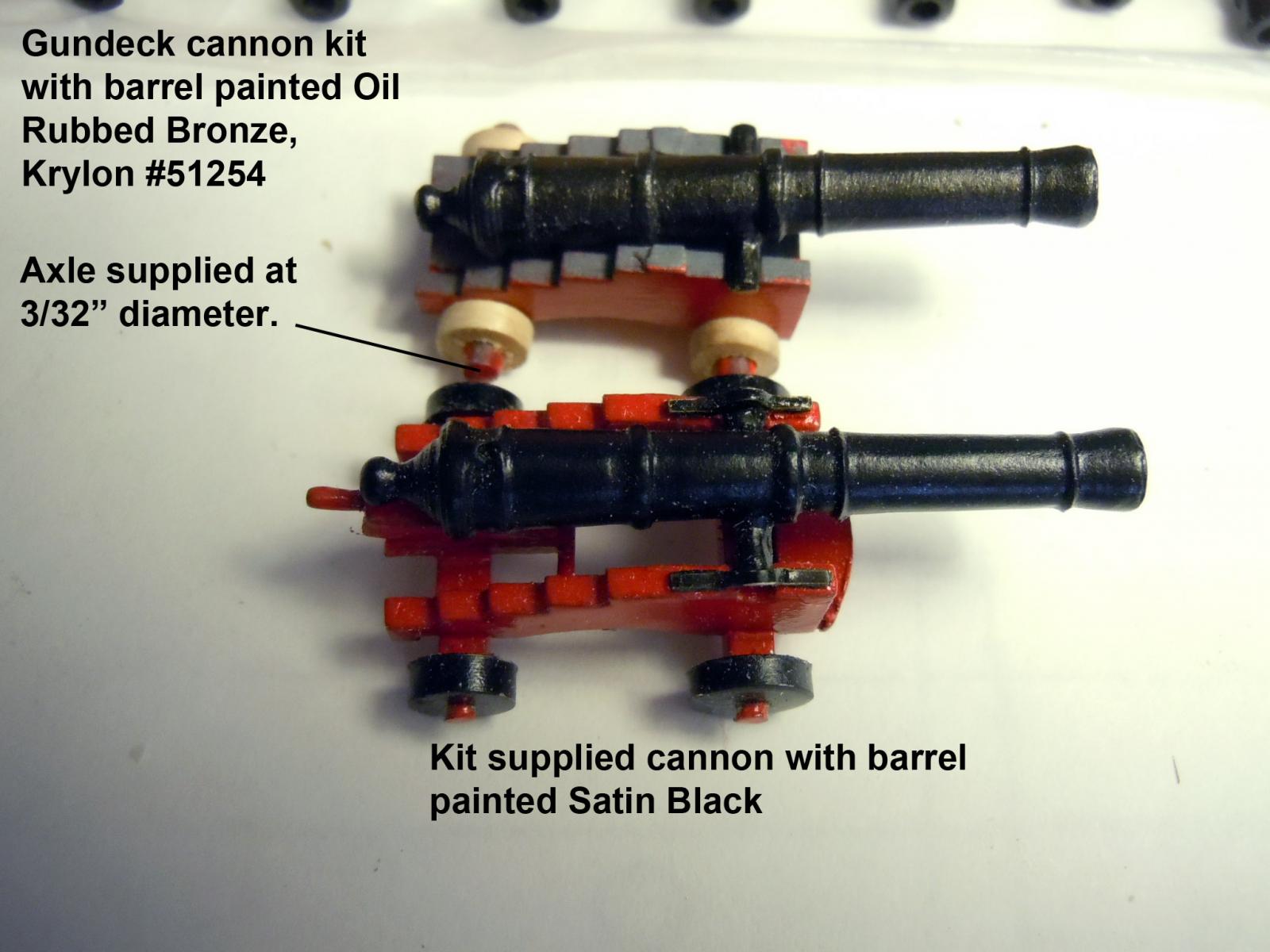
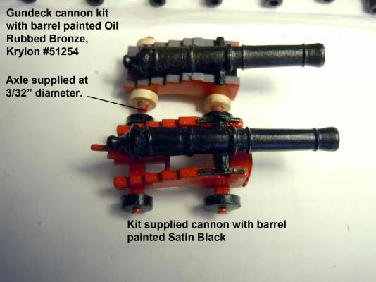
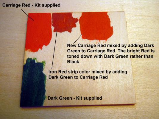
 Jon, thanks for the feedback on the rope, I have seen their rope walk and was wondering about it's effectiveness. I am working on the 30 gundeck cannons again the quality of cast parts and wood dowel choice were less than good. Of the 30 gun barrels only 2 were round with the rest being various forms of ovals; and a great deal of time spent to clean up. Also 3/32" dowel supplied for axles when it should have been 1/16" based on the laser cut holes in the wheels. I substituted 1/16" dowel which saved a great deal of time reaming the holes in the wheels just to fit the 1/16" dowel. I found a Krylon spray can Oil Rubbed Bronze that I really like for the barrels, It really tones down the harshness of pure black. I also tested the Carriage Red and thought it just too bright and pinkish so I fell back on my art education and checked the Munsel Color Wheel and verified that green was the opposite color for tinting versus adding black which would just change the value and turn it muddy. I also found by pleasant accident by adding too much green I had a great color for the Iron Red strip. I will tint the Carriage Red container to the toned down new red and have an ample supply for all the cannons. I will also be able to darken some for the Iron Red strip down the road. Here are some pictures of about three days of clean up. Here are the gun barrel colors, also the gun deck cannon kit design is slightly different the the kit supplied cannons. Here are the red colors I will use rather than the kit supplied Carriage Red; slightly toned down with the Dark Green.
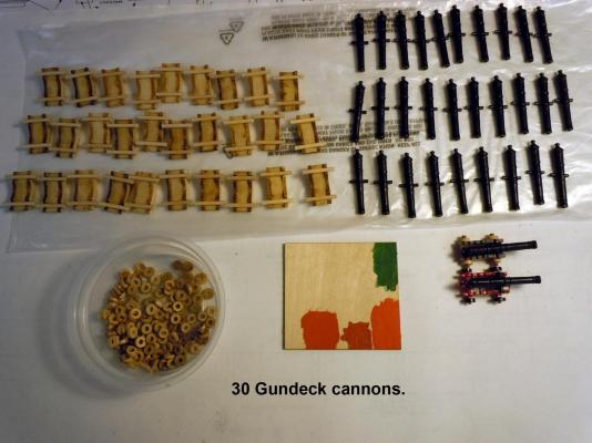
-
David, Here are some of my random thoughts on painting strip or otherwise.... go to an automotive outlet and buy a roll of 1/8" masking tape; this will provide a clean narrow edge. Once applied carefully burnish down with a piece of wood strip with the end cut at an angle to navigate the overlapping edges of the copper. Once burnished the way to avoid color bleed is to seal the tape edge with a couple of clear coats first let completely dry and then paint with color. Any bleed if done correctly will be minimized and if bleed occurs it will be clear. I use a Krylon Matte finish applied in light coats not full wet when spraying. Keep in mind the clear spray will adhere to the copper much better than any water based paint and the water based paint will require a couple of coats. Remove the tape as suggested above carefully and at a 45 degree angle towards the painted surface. Another issue on the copper plating based upon my build observation. I should have let my build set and "cook" longer in the sun to completely dry prior to coppering. I live on the central coast of California and my studio is an unheated 2 car garage vented to the outside and subject to heat swings overnight this time of the year mid 40"s to mid 70's and I am seeing what I think is linear expansion and contraction with exposed corners "popping" overnight. This is one of the reasons I am delaying my painting of the strip to the very end...one to stabilize the hull drying and second to avoid any damage due to the sensitivity of the paint on the foil. Non ferrous metals such as copper, aluminum and such should be primed with the green etching primer "zinc chromate". An acid etching primer is available at automotive suppliers; but is is gray and will run the risk of bleeding when sprayed on the bare copper. Again, just my rambling thoughts. Great job on the coppering so far!
- 117 replies
-
- 4
-

-
- constitution
- model shipways
- (and 1 more)
-
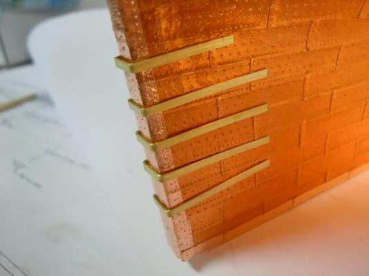
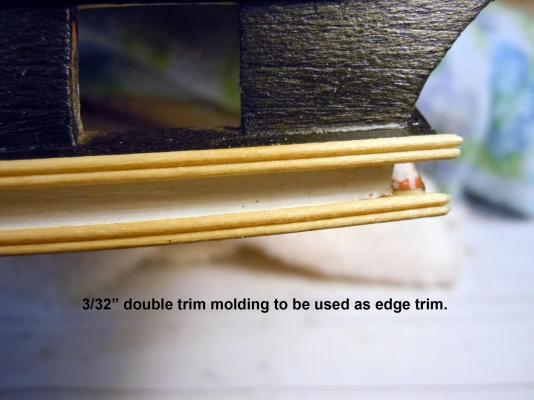
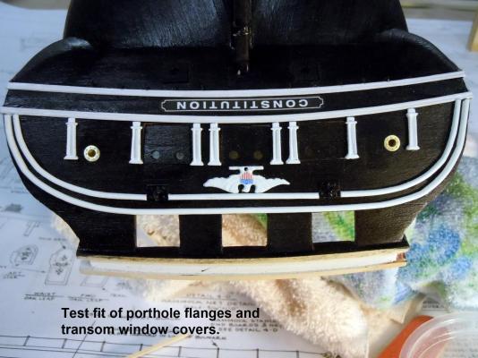
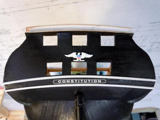
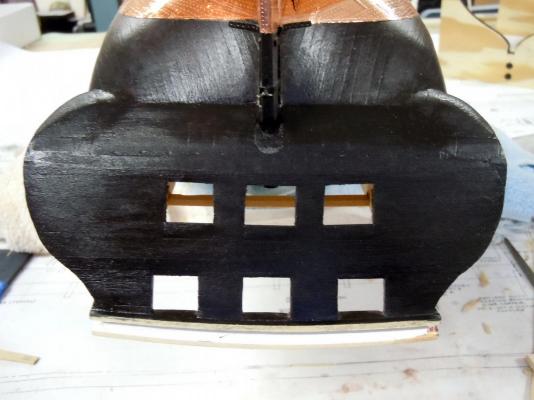
Finished up the porthole frames and installed them along with the pulling ropes for the window covers. While at a local dollhouse store looking to see if they had any stars; which they did not I ran across a supply of wood trims and profiles and the ones I thought appropriate for ship building I purchased. In the little treasure trove were several 3/32 double half round boxwood trim pieces that I will use to add to the edges of the main rails. Here is a picture of the trim in place on the transom rail before staining and again the height is 3/32" Here is a picture of the finished transom for now minus the anchor chain which I will add towards the end of the build due to its delicacy and my at times clumsy handling of the hull. Next I will ponder my next move which will include adding some of the rail trim and move on to building the cannons for the gundeck. Any tips or advice on painting the bow decoration strips and scroll work, hand painting is not one of my strengths. Also still waiting for any thoughts on rope walks and making of ones own rope.

-
David, thank you! It is getting there slowly but surely. In looking around I saw one build discussing lighting and I also saw some with bolt heads in the inner walls and thought I would share this link to a sight for 1/8" brass nails which are great for round headed applications and also all the electrical needs for lighting. While this is a dollhouse site the electrical products might have ship application for lighting. I forgot to mention the round head diameter is .048" or about 3/64". http://cir-kitconcepts.com/shop/index.php?main_page=index&cPath=12
-
Don, yes it is a self centering and what it is great at with the four jaw is holding square brass stock and turning down square headed bolts. The Sherline is precise enough I have turned down 1/16" square headed bolts. In fact, Kurt could attest to the quality since he used cast ones on his Allerton build. I have also used the lathe to seize shroud lines as well, works best with the hand wheel.
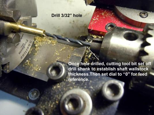
-
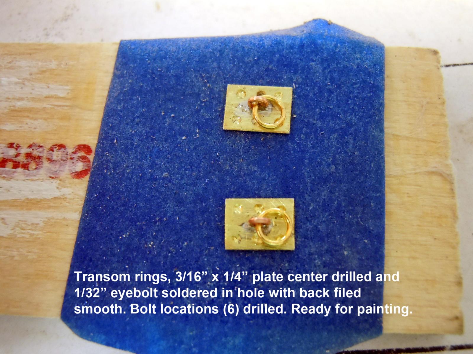
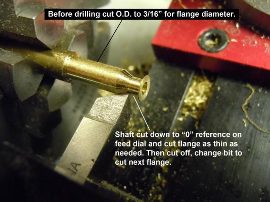
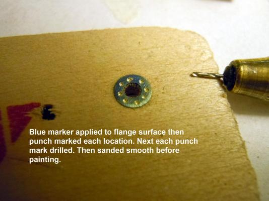
Before I could added the molding I needed the transom rings which I fabricated with brass sheet, twisted eyebolt soldered in center then drilled for bolt locations. Once finished they were glued in place and molding added being cut and fitted around them. Next the window covers were cut and fitted with both halves glued at center joint. Then I decided that the windows really needed their flanges. Here is a sequence show how I cut them on my Sherline lathe with the thickness of the flange being .008" thick. Here you can see the results in place, but upside down. Now to cut the rest of the window flanges 2 down 8 to go. Thinking ahead what are builders thoughts on a rope walk and making one's own rope?

-
Jon, my guess is that you are correct and I think they would be water slide decals.
-
Found a source for stars; best option so far looking at the 5/16" and 3/16" gold stars. Let me know your thoughts, right now the 5/16" might be just a tad too big. I like them for there definition and crispness. https://www.usamilitarymedals.com/collections/devices-attachments?page=1
-
Kurt, tell me about that spin caster you have, ie what type. Anybody have a source for 3D stars for the transom of the Constitution?
-
David, here is a start check this link: http://www.hobbylinc.com/cgi-bin/s8.cgi?cat_s=UPB&tag0_i=873 Kurt, don't tell me tell Marc he needs to get it into production.
-
David, the only way is with white decals. White can be printed but only on an ALPS printer which are usually commercially owned. Just need to find a decal supplier and send the artwork. Another option is finding a railroad decal number set or maybe a couple. When I have time I may check around for some.
-
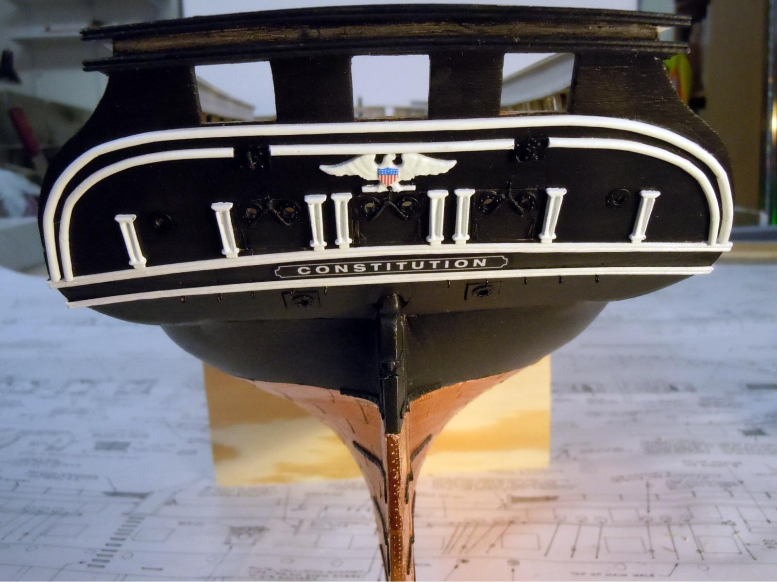
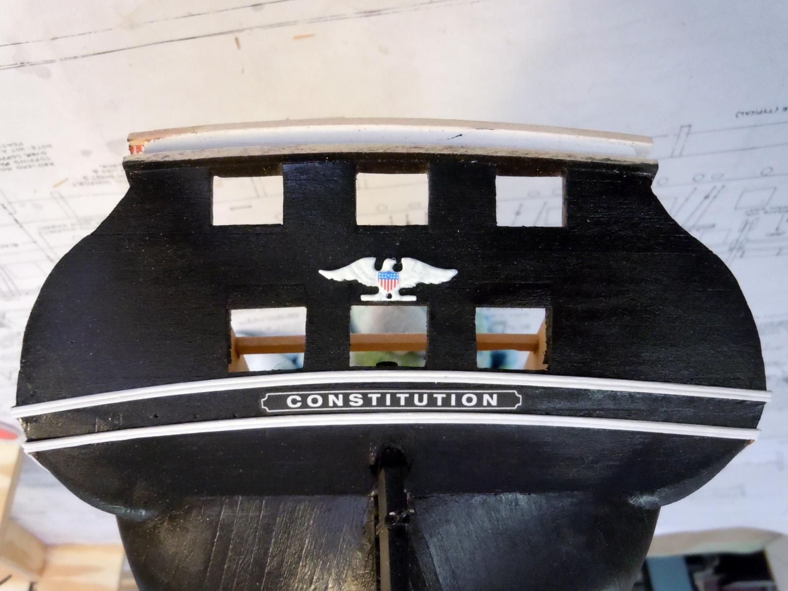
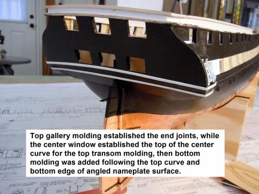
Tried painting the nameplate with a 0000 brush and I did not consider it acceptable. I fell back on Photoshop and did the nameplate, the eagle shield as well as the bow stars and shields. I am working on the curved molding and need to fabricate the ring plates prior to adding them. Here is a picture of the eagle and nameplate as well as the artwork I did to share with others; however only for personal builds no copying for resale applications. For sizing reference the eagle shield is 5/32" high; length of nameplate is 2" black edge to black edge. Once I printed them I sprayed the paper with Krylon Matte Finish; first a light coat to set the ink and then a heavier coat; this aids in stiffening the paper and easier to cut with scissors. They were glued in place using Carpenter glue and a light coat applied on the back of the paper with a toothpick. The nameplate corners may need trimming and edges once cut out blackened with a black marker. Now to fabricate the ring plates.

-
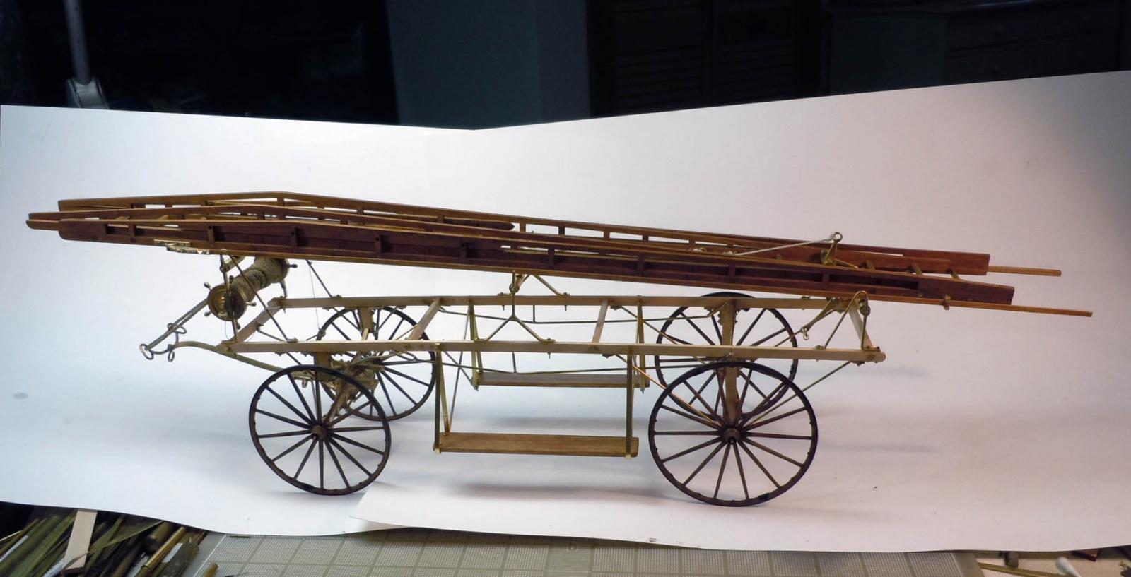
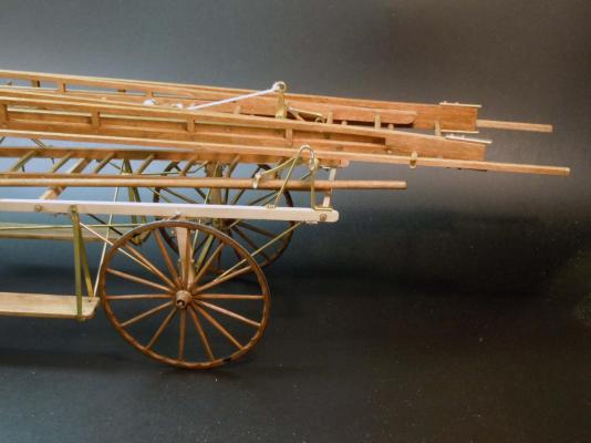
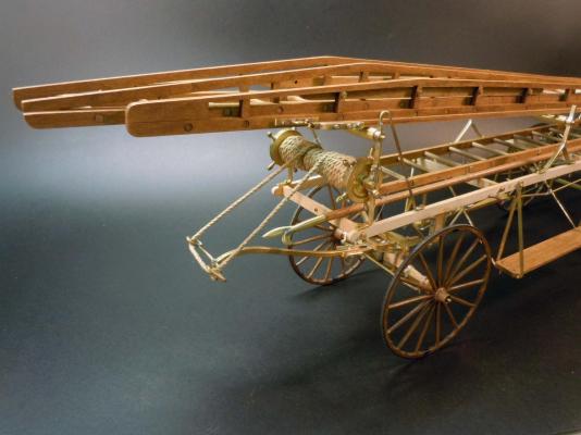
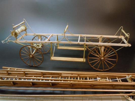
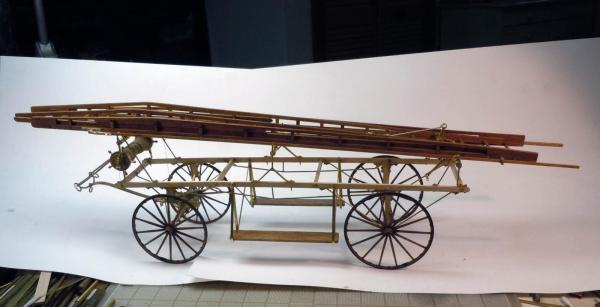
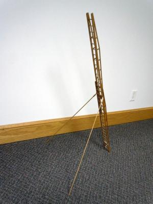
]Kurt, the Ladder Wagon was completed and delivered the Hearse is on hold, just need to complete the plans and instructions when I get the go ahead. Here is the Ladder Wagon prototype with working ladder.
-
Kurt, If you ever wish to pursue casting parts I could connect you with the guy that did the Allerton parts his work is excellent and reasonable. On the 00-90 bolts he even captured the threads enough to be able to thread a nut on.
-
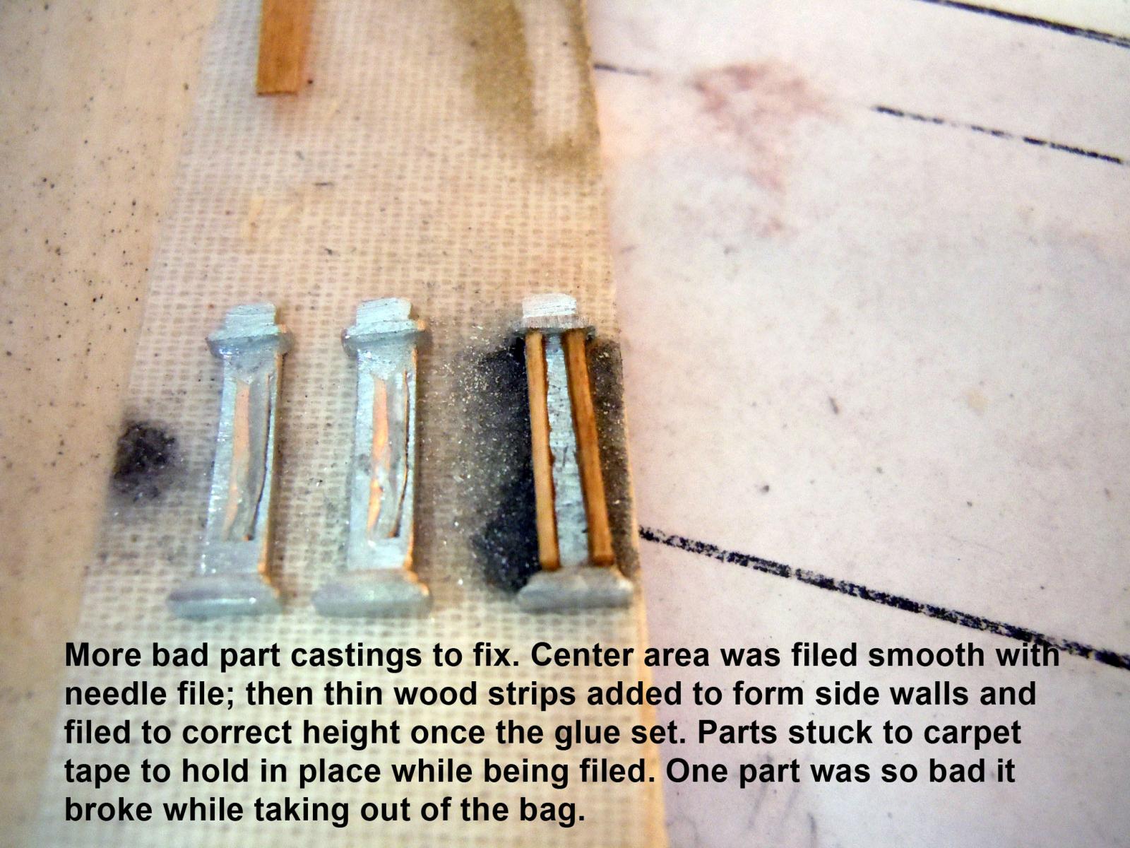
George, you are absolutely correct and this is the reason why I started scratch building years ago. Raw materials are much more cost effective and no one else to blame than yourself. I have designed kits for Model Expo and the castings I received were much, much better in quality than these, then of course I supplied the master parts for the molds to be made from and worked directly with the supplier.
-
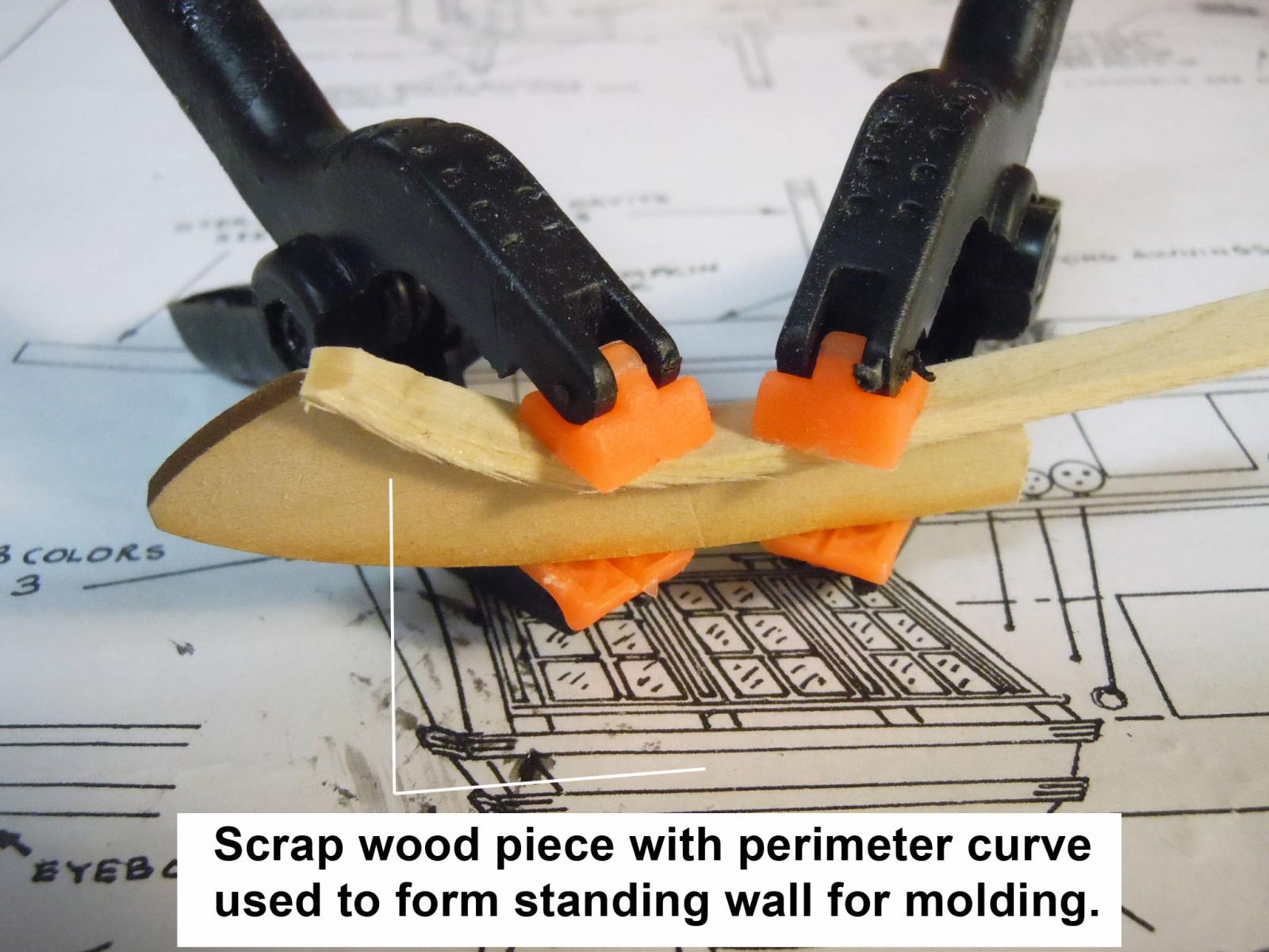
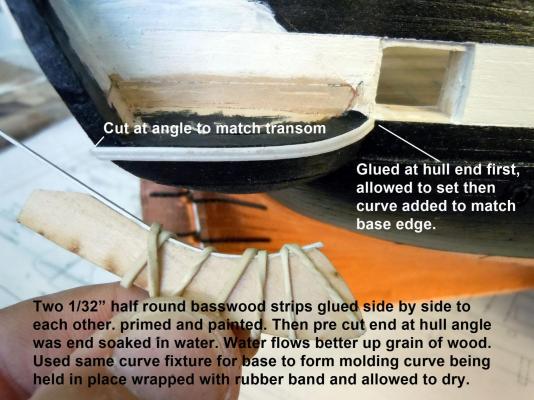
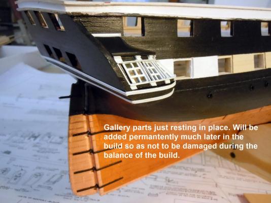
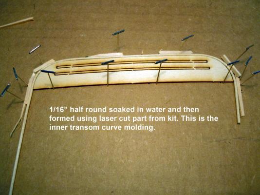
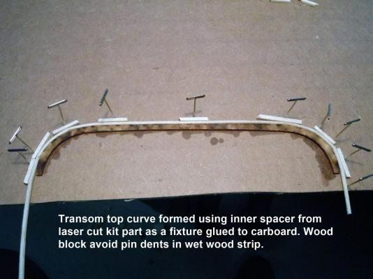
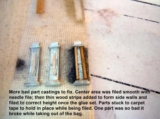
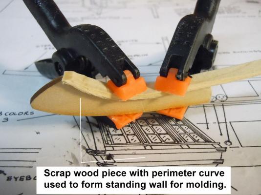
Had some fun time with the granddaughters so my daughter could have a business meeting. Moved on to adding the gallery and transom moldings after making new ones at a smaller scale of 1/32" half round strips made with brass cutter. I will leave the gallery components off until later in the build to minimize potential damage while handling the hull. Here are in progress forming of the curved transom moldings, the kit ones were junk in my mind and out of scale as well. I am using 1/16" half round moldings again using my brass cutter. While waiting for moldings to dry I turned to the metal castings for the decorations around the windows; and much to my surprise more junk castings. One even broke taking out of the bag; glued the pieces to a 1/64" plywood carrier to save it. Now back to fixing the above parts, not a good one in the bunch.
-
David, you are off to a great start! Did your copper rolls match?
- 117 replies
-
- 2
-
-
- constitution
- model shipways
- (and 1 more)
-
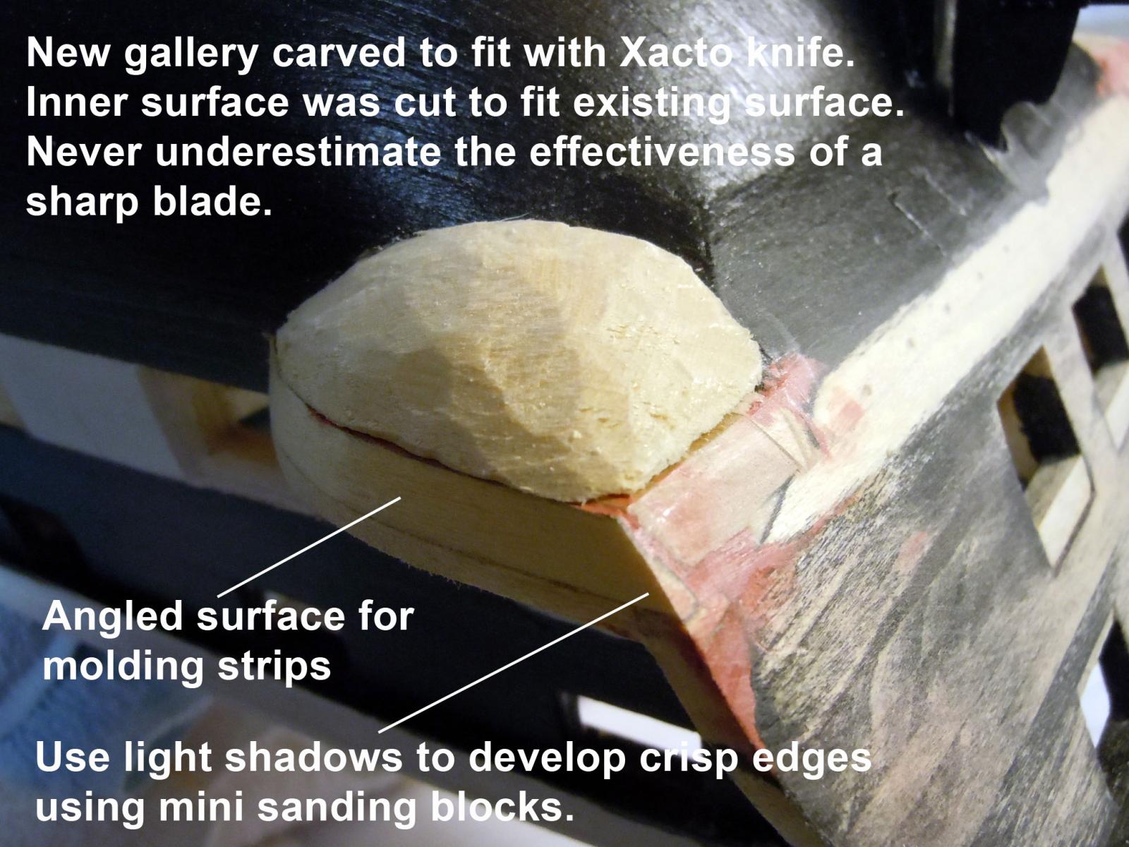
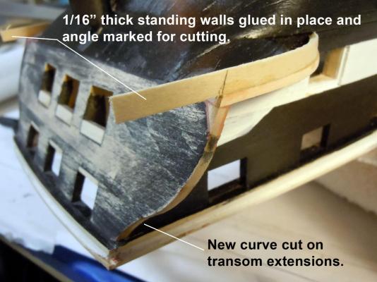
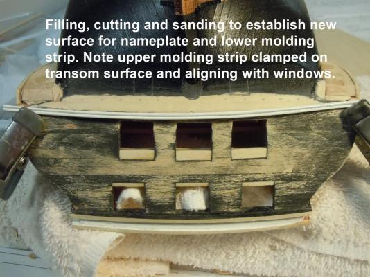
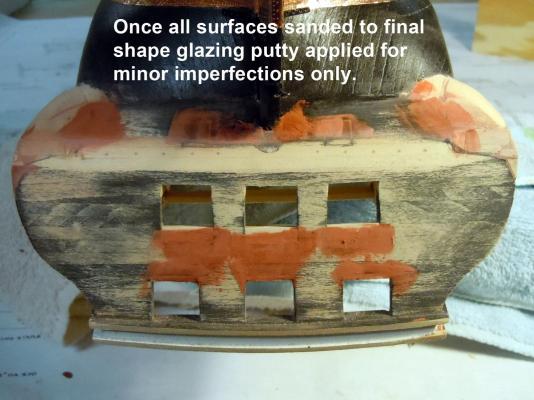
Thank you all for your kind words and encouragement! I look upon this rework not so much as a mistake, but a lesson in ship building and an opportunity to hone my wood working skills. It should also be a warning to add the gunports first, take care with the rework of the transom framing (page 12) and only add the transom extensions (page 13) after the gunports and align the bottom edge with the gunports. The extension parts are laser cut too short (1-5/8") by about 1/8" the difference of 1-1/2" on plan rear view; versus the side view of 1-3/4" (angled). Anyway I am back on track and here are pictures of the stained rework and some of the wood definitions can still be seen along with rework joints which will be blinded up with molding and decorations. Now I will add the new molding I made while waiting for stain to dry using 1/32" half round to the angled side surfaces first and then to the transom. After they are in place then the rest of the transom will be addressed. Again thanks for your words of encouragement.
-
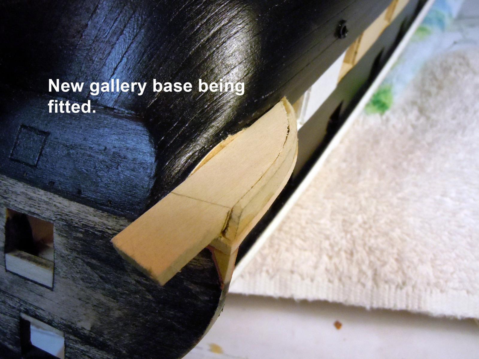
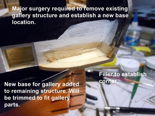
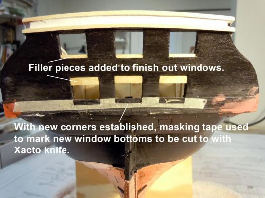
Well my inexperience of ship building reared its ugly head again and not understanding certain relationships of ship elements. However, in looking around at previous builds I see others did the same which lead me back to the instruction manual and page 13, Fig 1-11 adding the transom extensions. In my opinion these extensions should not be added until the gundeck and spar deck gunports are framed in. Then the extensions should be added and aligned with the bottom edge of the gunports to get the galleries located in the correct position. This also assumes the issues with the transom framing is sorted out as well. The following rework is for the benefit of those who will follow since there is no clear instructions in adding the bottoms of the galleries and molding which are critical visual elements of the build. The pictures are self explanatory and questions or suggestions are welcome. The solution I am describing is based upon looking at several pictures of the real ship and the interpretation of them. Once finally ready, I will add the pre stain wood conditioner and then the black stain and then clear Satin finish. The one regret is that I will lose the wood board definition due to the previous staining process filling the grain and now being sanded. Hopefully the transom molding and decoration will mask this up. The lesson I have learned is to refer to the pictures of the real ship, check the plans and resolve any differences. I will look at the instruction manual with a real jaundiced eye; but I am learning more about ship building.


-
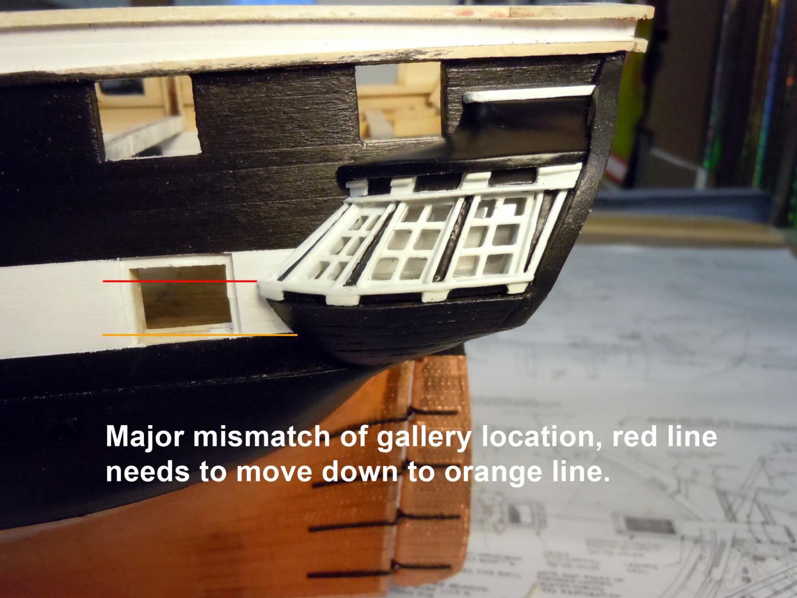
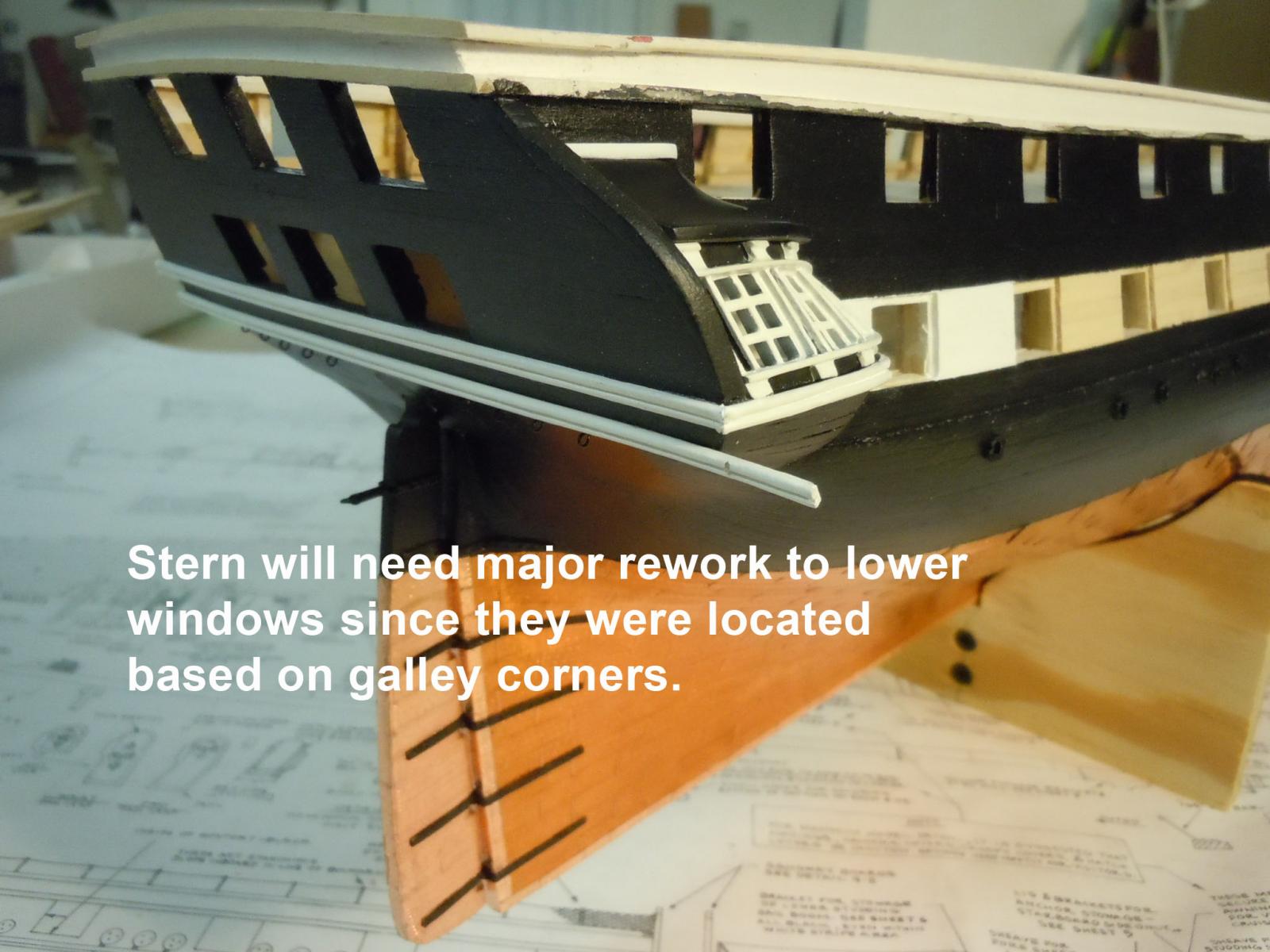
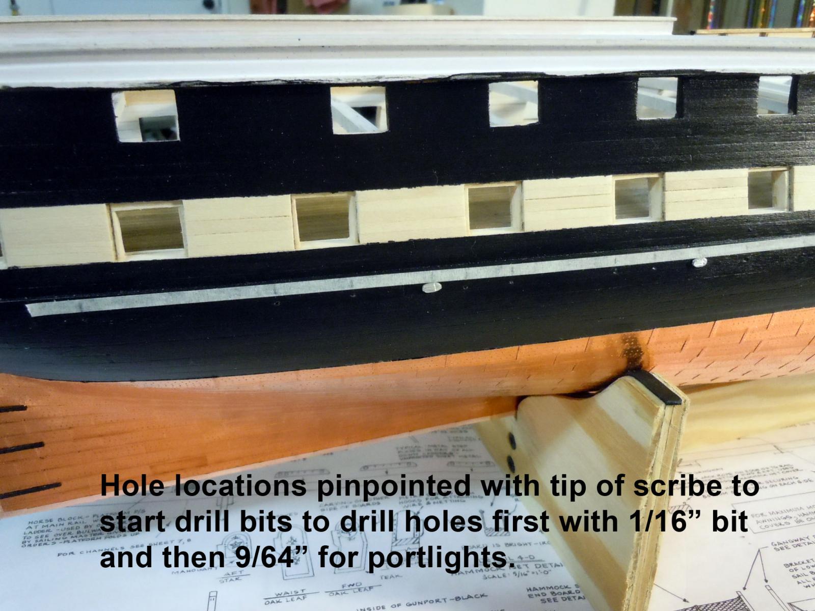
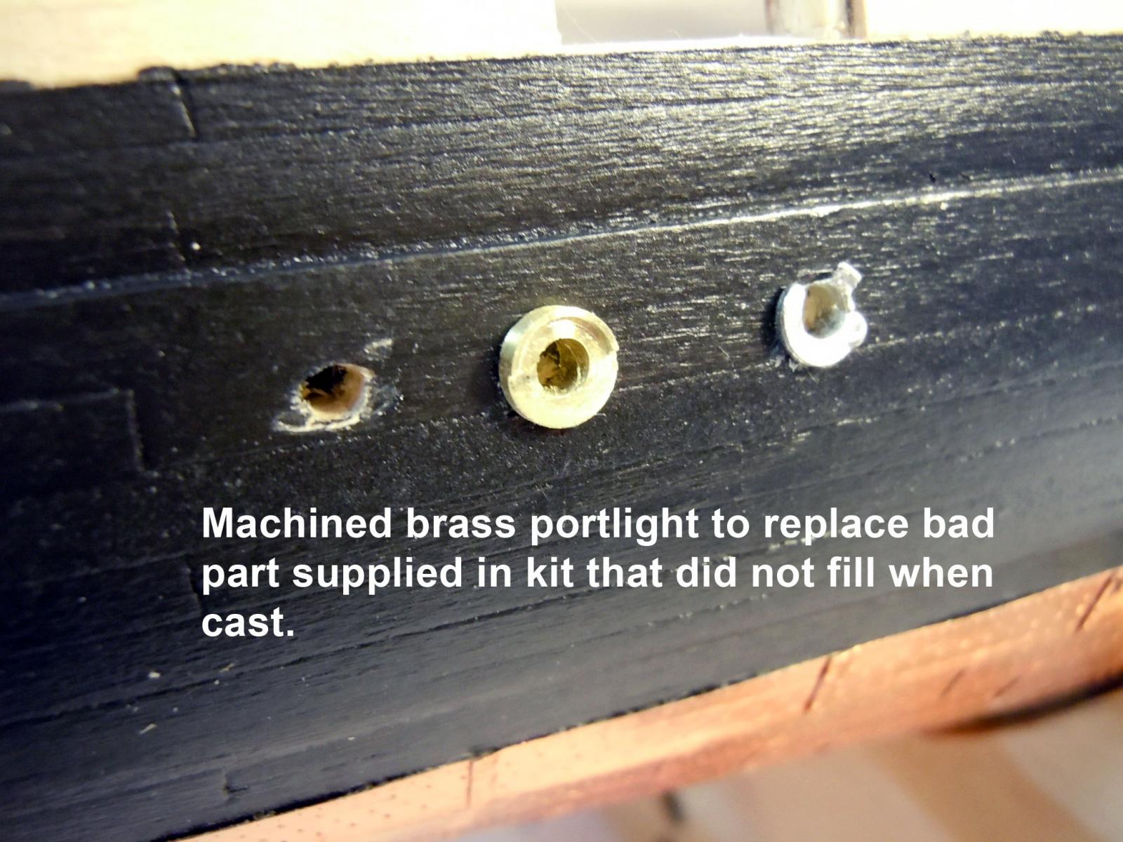
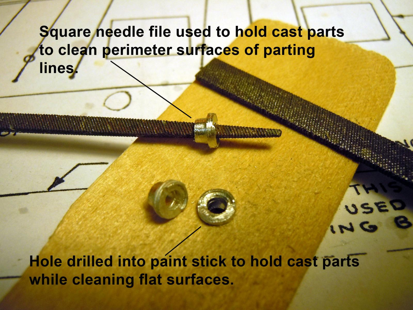
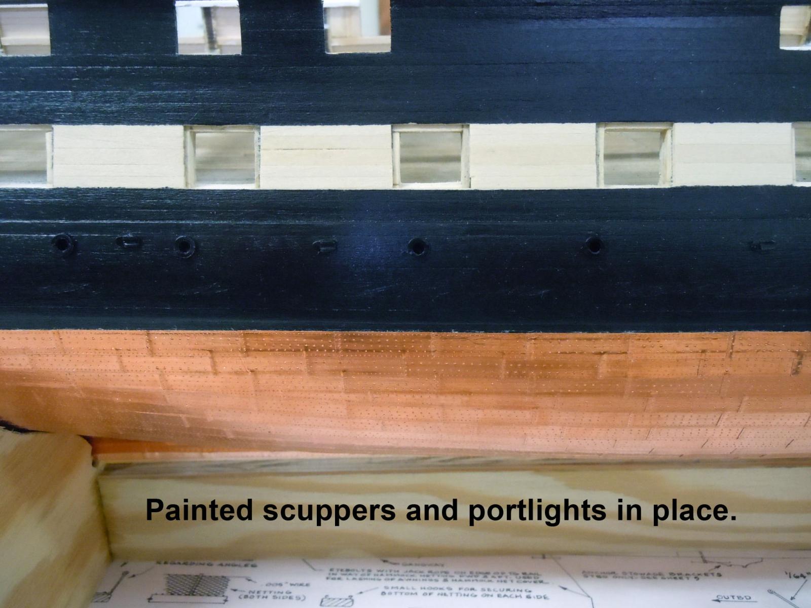
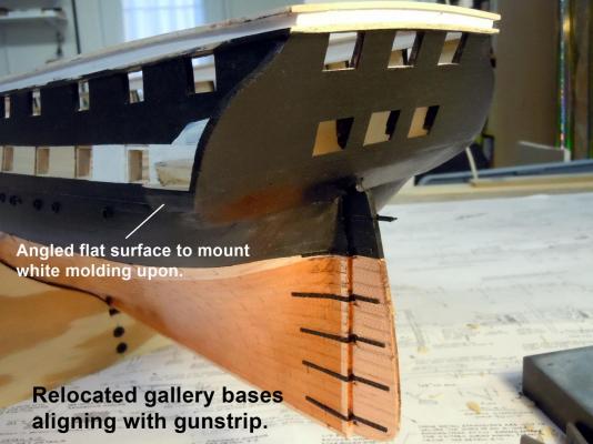
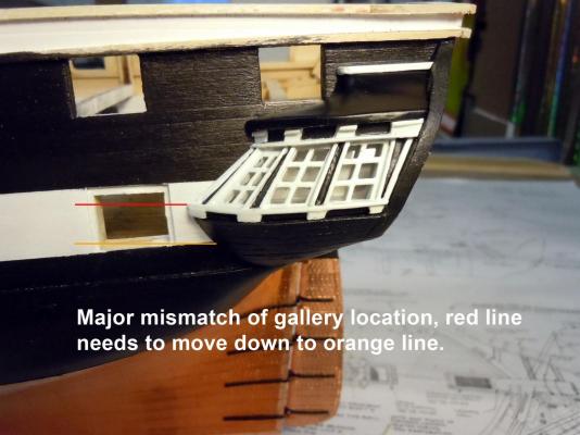
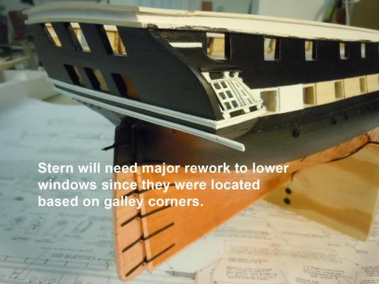
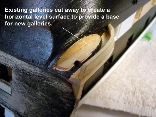
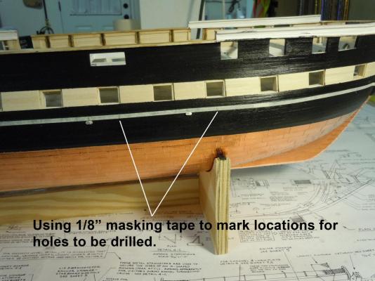
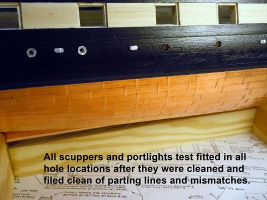
Moved on to the portlights and they required drilling holes in the hull; measuring locations was critical. also it turned out that one of the castings did not fill when cast; so I had to turn one on my lathe. I used 1/8" masking tape aligned with the top edge of the wale to use for marking the locations for the scuppers first and then the port lights. Here is the incomplete cast port light; should not have been included and is just a piece of scrap. Just a tip for holding the lights to clean the parting lines and true up roundness. The back edge of a Xacto blade tip was used to scrap the face smooth. It is hard to photograph black on black but here they are in place. Moved on to the stern molding and discovered a major dependency with the gallery locations that will require major surgery and rework since they did not line up with the white gun strip. Once I sort things out I will post the rework and what I think caused the problem. In checking other builds I see the same problem that I have which I think stems from the issue with the transom framing. It will be a major rework.


-
Jonathan, You are correct the . is next to the / on the keyboard, it should have read 1/32" (.032"). At times my brain works faster than my fingers and my eyes just overlook everything. Just keep me honest!
-
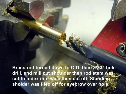
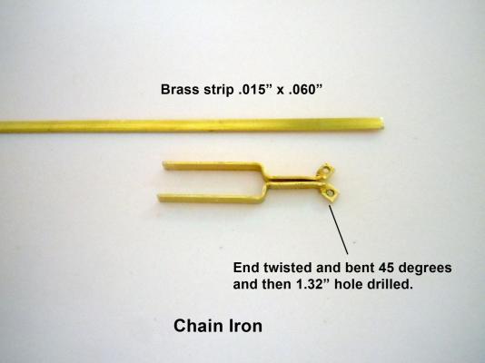
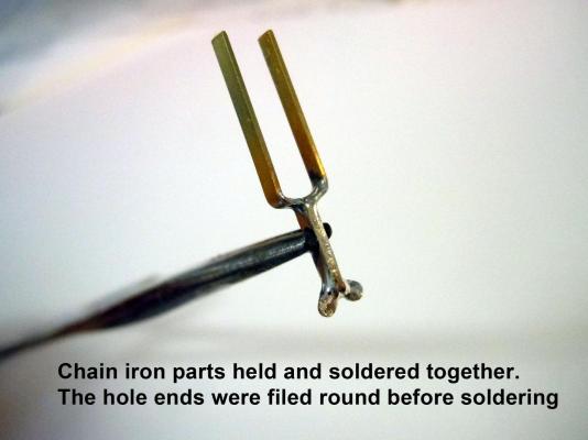
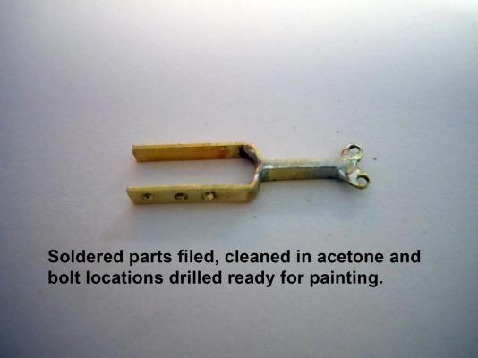
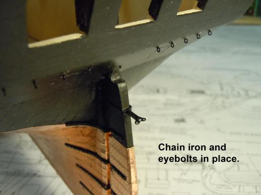
Here is how I fabricated the chain iron using a brass strip and making two identical parts and soldered together. They were just bent and formed with small pliers. This shows it in place and I also added the chain eyebolts that I formed using black anodized copper wire twisted around a 1/32" drill bit shank. Next will be the scuttles and portlights. I see already that I will have to make one since one was only partially filled in the casting process.
-
George, Thank you the plans and instructions were a little sketchy about doing it. David, peel back both rolls of tape to see if they match. Usually at least two lengths of the roll.
-
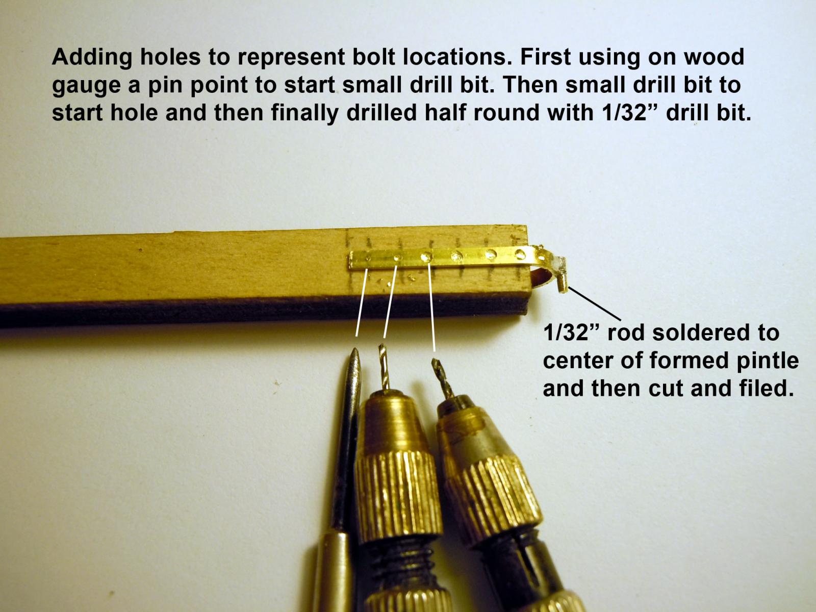
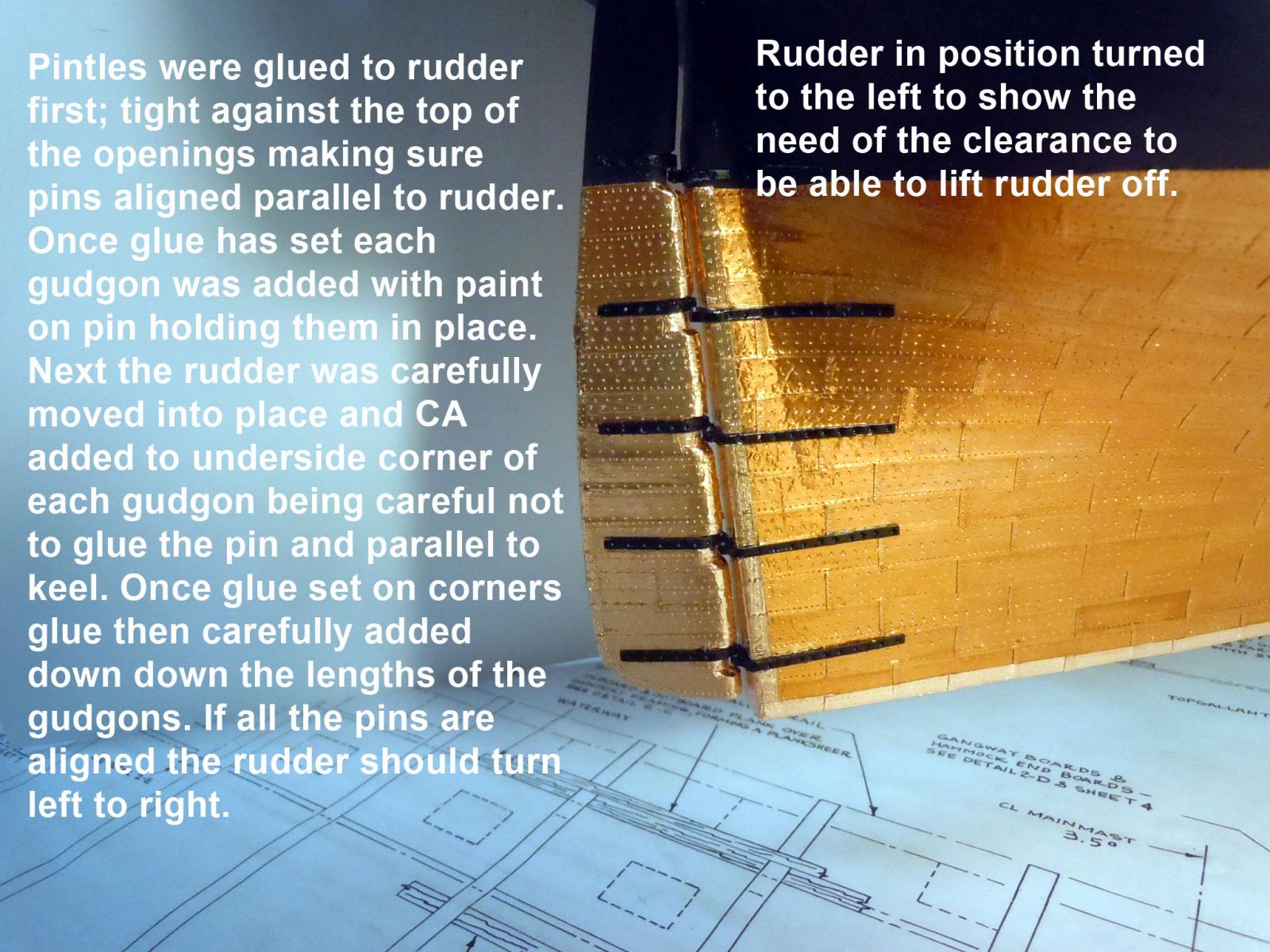
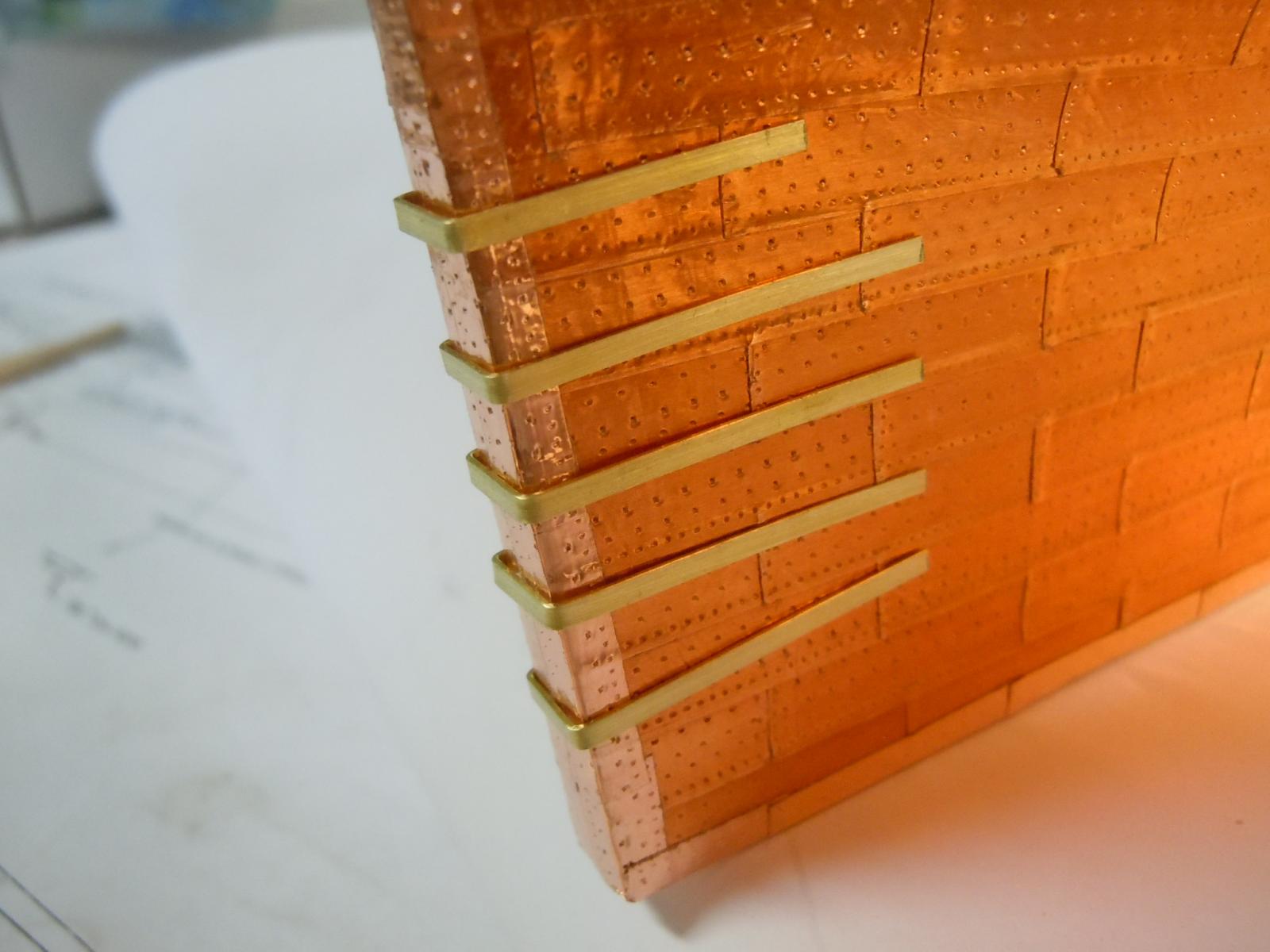
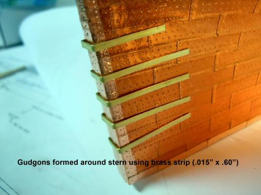
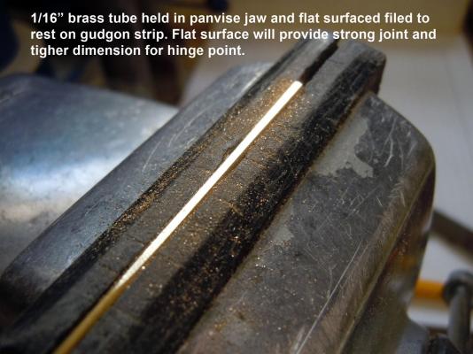
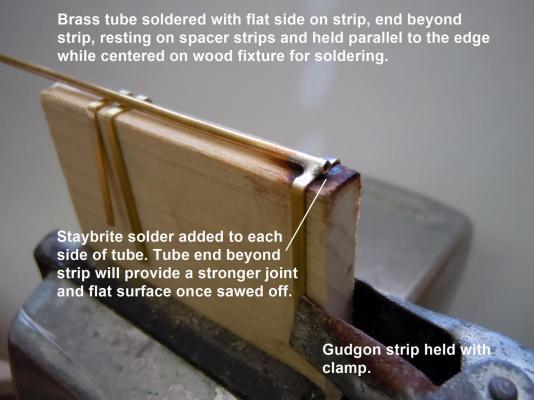
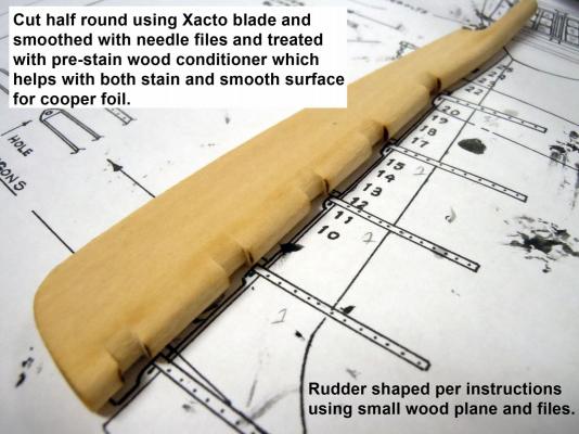
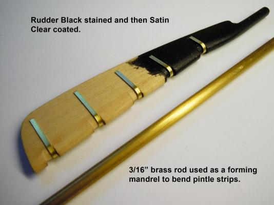
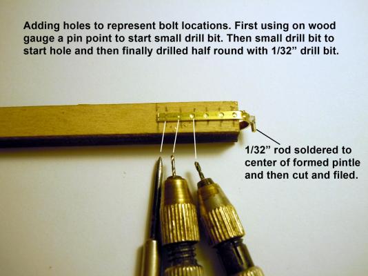
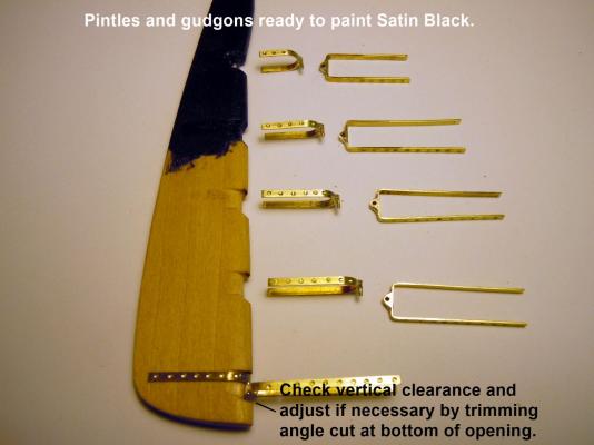
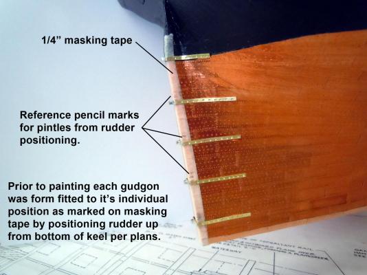
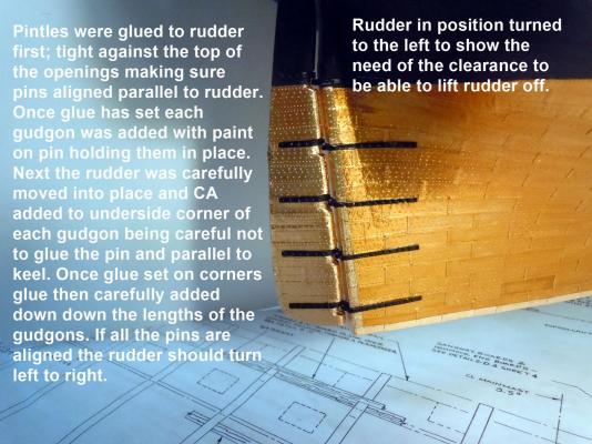
Back to building after having out of town guest for a couple of days. I finished up the plating of the hull with the two tone copper foil. After checking around and discussing with my wife who is a silversmith the best solution for now is to leave the copper foil alone and let time do it's work. The big concern is that any polish or chemical treatment may cause the edges to lift and create a bigger problem. Since I still have plenty to do on this build time is not an issue. I moved onto the rudder and wanted it to be movable so I used a stronger brass strip (.015" x .60") than what was provided in the kit. I also used 1/32" rod and 1/16" tubing to be the hinge elements of the pintles and gudgons. On critical point is that when soldering make every attempt to make sure the tube and rod are centered when soldered in place for a good functioning five point hinge. Here is a sequence of pictures that are self explanatory; but if questions please ask. One other thing I discovered is that the pre-stain conditioner is great for adhesion of the copper when dried and sanded. I did not include the plating of the rudder which is pretty straight forward. Next onto the chain iron as long as I am in the stern area.
-
David, Here is a picture that may help. I started at the stern corner using the full size plates and added the first plate halfway down the stern post then cut it to the corner then pressed the second half onto the stern post; then folded the second half of the plate onto the keel and pressed into place with half on the side of the keel and half on the bottom of the keel. Then subsequent plates would overlap correctly forward to the bow and up to the water line. In short the plates were bent in half down the keel on both sides overlapping to the bow.