xken
-
Posts
841 -
Joined
-
Last visited
Content Type
Profiles
Forums
Gallery
Events
Everything posted by xken
-
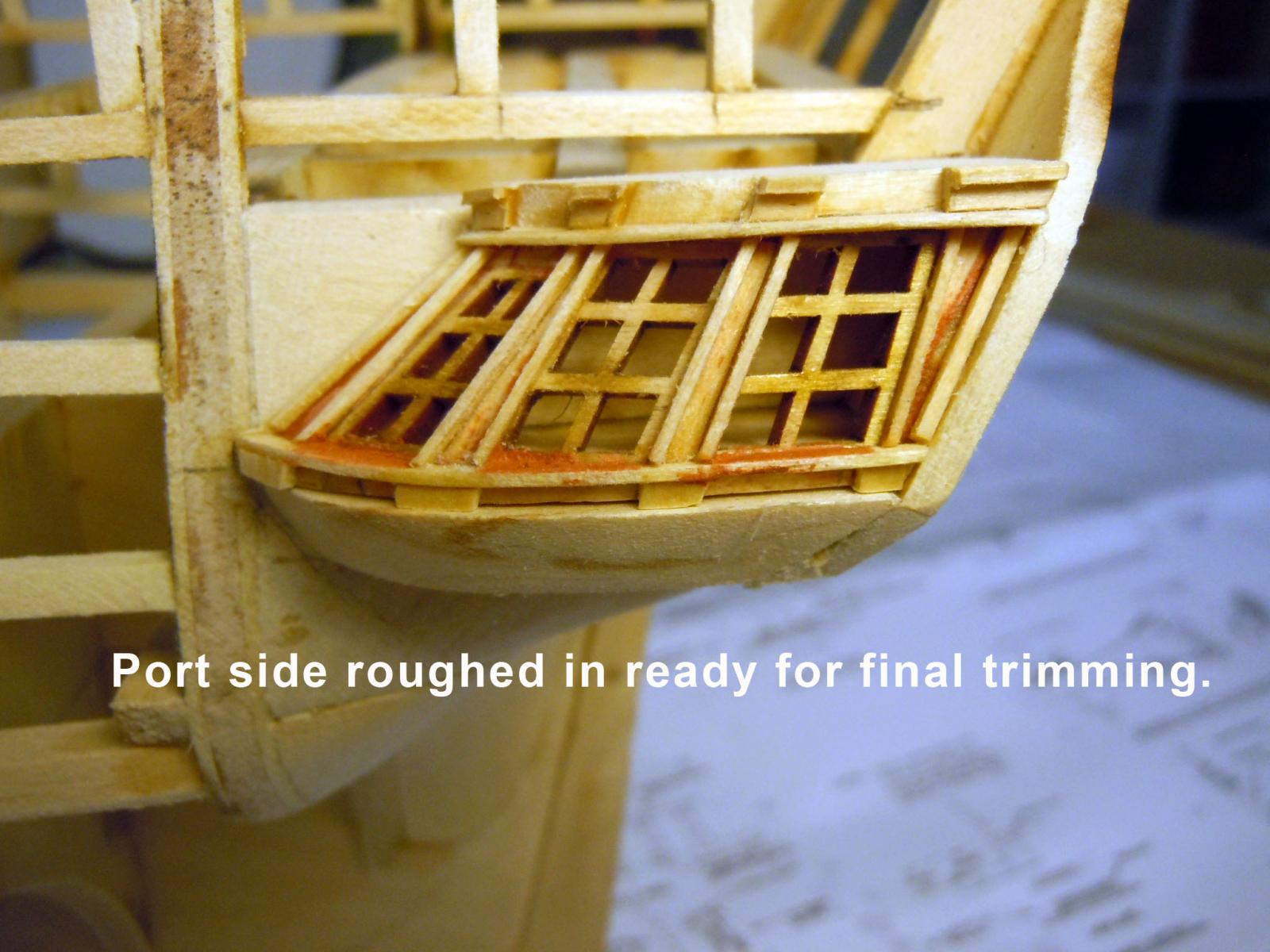
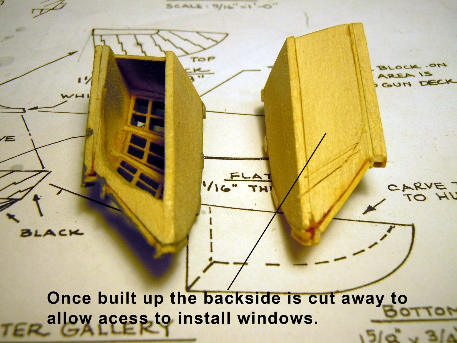
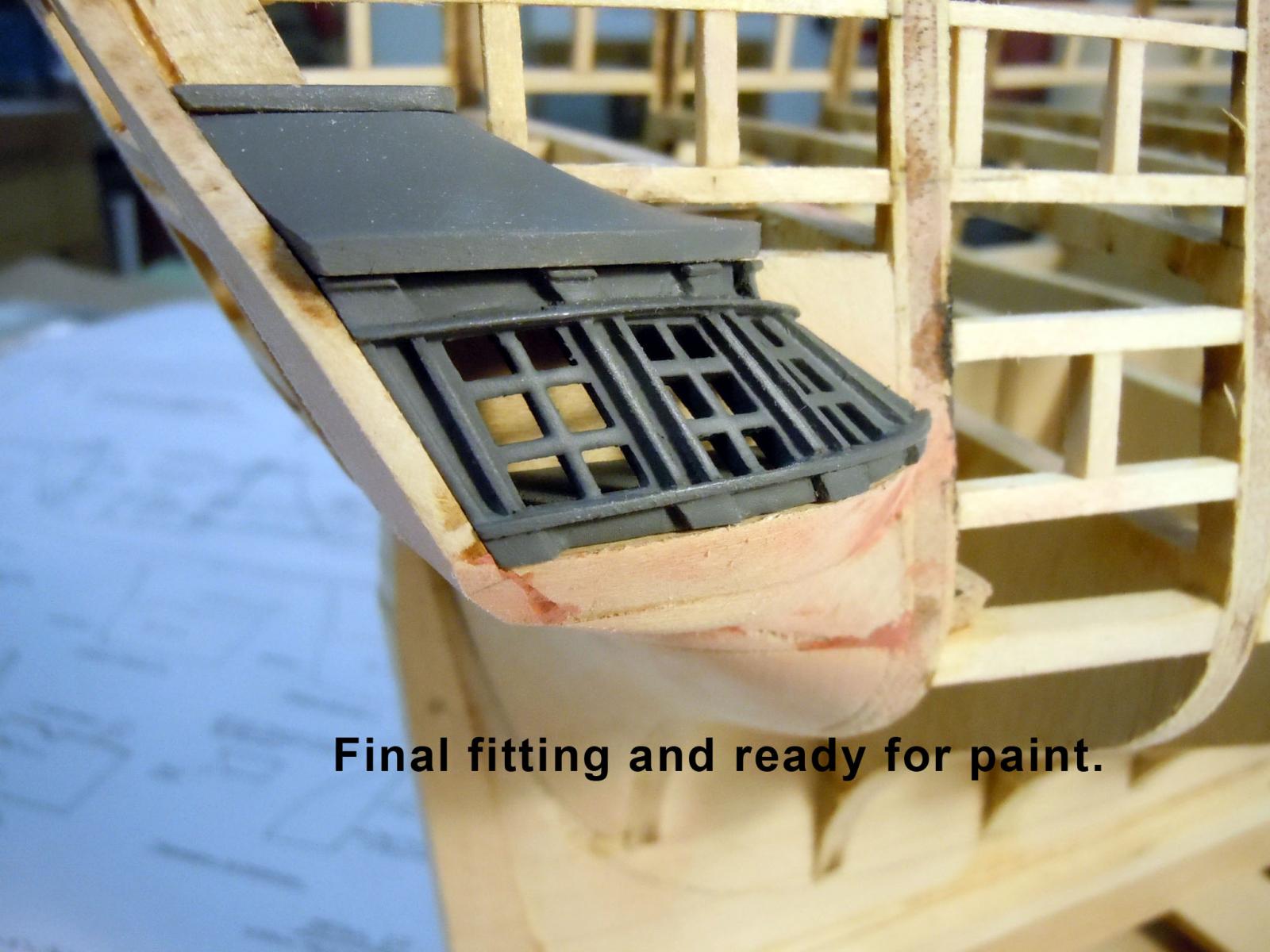
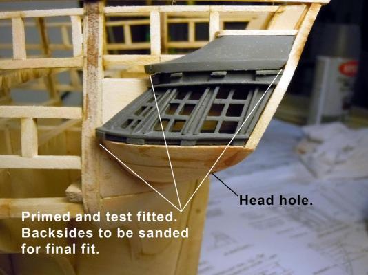
 After much debate with myself and checking other builds I decided to do the best with what is provided with the kit and the direction specified which is C2/6 as shown by Captain Steve's options. Here is the rough in of the laser windows and you can readily see the problem with the window closest to the hull. The bottoms of the windows are parallel to the base line but the tops are off on a tangent. I am making the window sections removable for easier painting/replacement down the road. Here is the port side roughed in to match the starboard side. Here is how I made the removable section structure and once built the back side was cut away to allow painting and window installation. Here the parts are primed for final fitting and adjustment by sanding the inboard sides of the components. This shows the final fitting of the starboard side ready to be painted later. I also added the bottom filler with the head hole drilled before forming. Next I have moved onto the transom and added the gunports and now have to decide whether to continue with the kit direction of only three windows or add five windows as I have seen on other builds. I would welcome advice and background of the three versus the five window transom. I have heard that my order for deck strips will ship today.


-
Captain Steve, thanks for sharing! It looks like the center one is what is drawn up on the plans and I am presently building with out of scale details. I will just do the best I can with what I have. Thanks again!
-
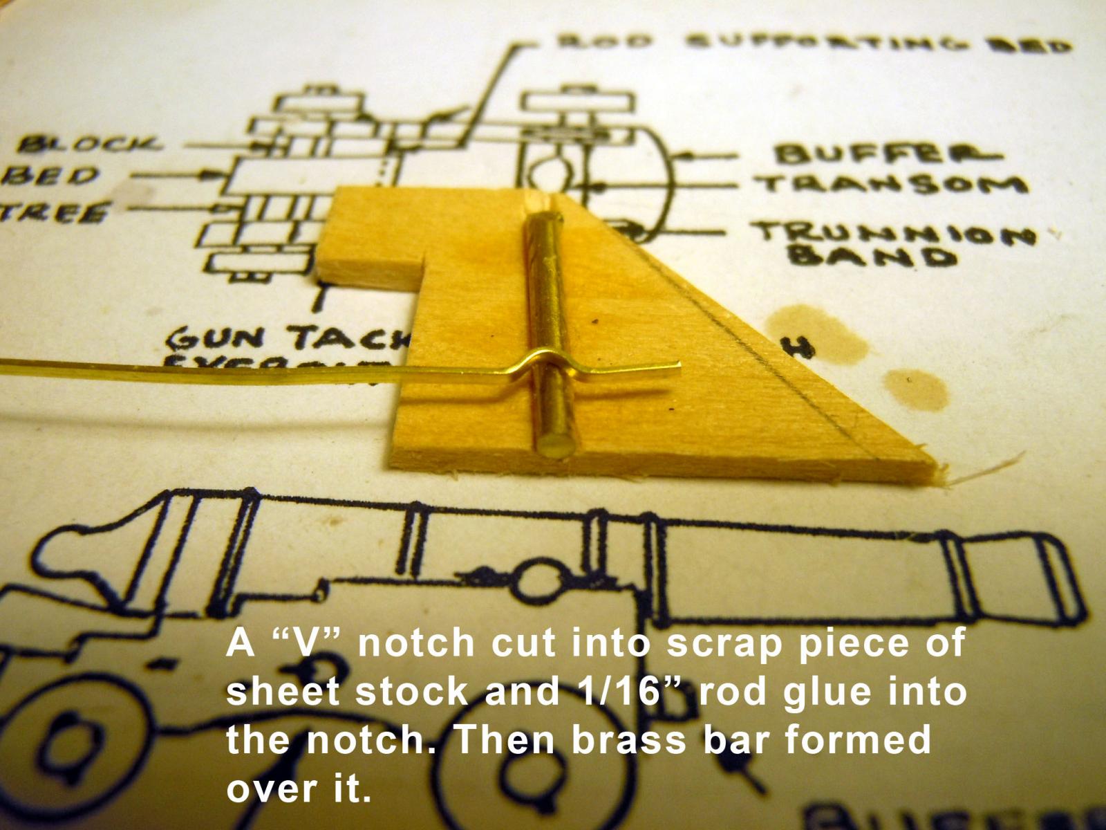
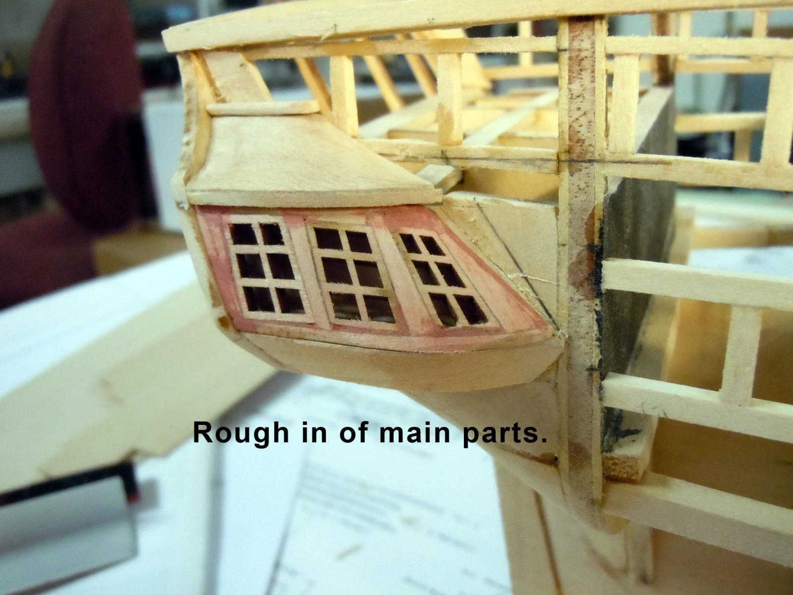
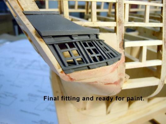
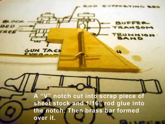
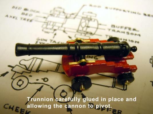
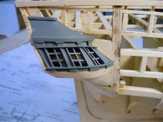
Tom, thanks and here is the rest of the gun. I used the brass strip supplied with kit and stretched it to straighten. I cut a "V" notch in a piece of scrap wood and glued a 1/16" piece of rod in the notch about halfway down. I then formed the brass strip over the rod using the blades of a common screwdriver. Cut the straps to match the forward edge of the carriage and matched the length on the other side. Here they were very carefully glued in place with drop thickened CA so as not to glue the cannon trunnion so that it will be adjustable with the quoin in the gunport. Next while waiting on the deck strips to come I decided to build up the quarter gallery areas. I really struggled with the window shapes, but first carved the bottom filler piece at the required angle and dimensions off the plans and glued it in place parallel to the base line. I then decided to build a removable shell that holds the window area and glued the back piece the height of the windows and parallel to the bottom filler. Then added the angled rear part the required height and then the top shape again based on the plans. This formed the shell. I assumed that the bottom of the windows were parallel to the baseline as well. I then started adding each window and the filler blocks on each side and carved the top filler per the plans. In my mind the windows look odd angling down. It seems as though the window laser pattern was taken from a side view rather than a straight on view which accounts for the awkwardness in appearance. I almost decided to scrap the kit parts and scratch build them to look right but I could not find a clear image anywhere showing the inboard window detail. Here is an "in progress" of the parts so far with some fussing and trim work needed. I have to say quite a bit of rework was needed to get to this point and try and make the windows look correct. I just wish I had a good reference image; most of what I find are side views or rear views not showing the inboard window. Anyway I have made the section removable for either easier painting or replacing if I find better reference material.


-
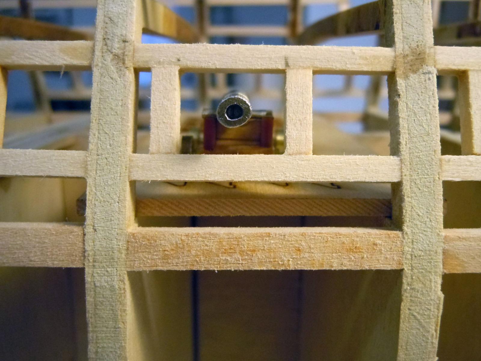
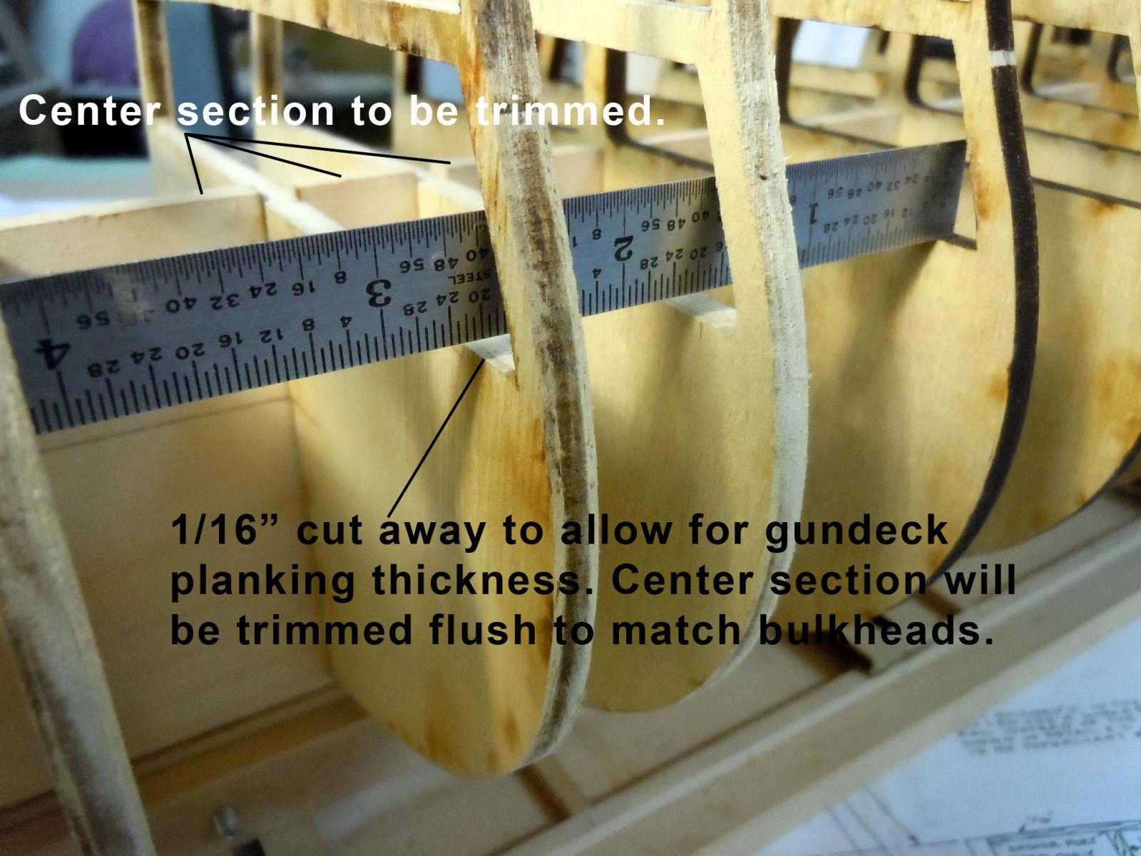
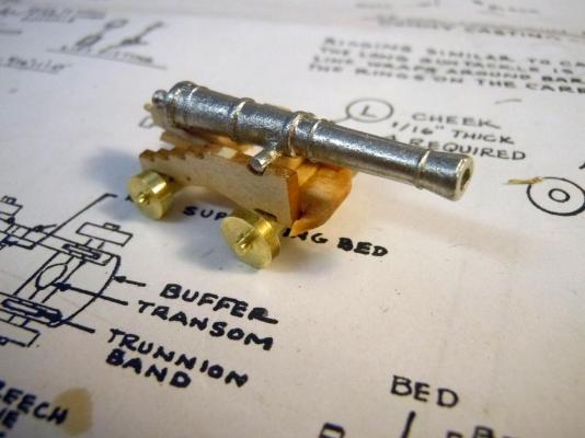
Tom, Here is the long gun built up. I turned the axles and wheels out of brass for accuracy the front wheels are 1/4" diameter and the rear are 7/32" diameter. The quoin is at the rear most position and can be slid fore and aft to adjust the barrel in the opening. I am assuming that it is suppose to be centered. Here it is centered in the gunport opening on the gun deck. I also had a brain fart and misspoke above; I only cut away 1/16" on the bulkheads not 3/32". The deck I will fit in place will be 3/32" thick so I think I am good for now on where I am headed. I also will smooth more on the barrel and true up the opening. Hopefully I will get my order soon for the 30 long guns.

-
Tom, thanks for the heads up! I am learning that the assembly instructions and plans are merely guides and are to be taken under caution. I am reminded of the old carpenter's adage " Measure twice and cut once." They are more like "Here it is you figure it out." The one good thing about building ships there are many independent components that can be built separately. Thanks again!
-
George that is what I was referring to about the dimensions on the planes. For the gundeck I removed 3/32" from the bulkheads to compensate for the deck thickness 1/16" planking + 1/32"plywood carrier and used the plans as reference lines. But that still does not mean it may be correct. Maybe I should build a cannon and verify while waiting for the order to come. Now is the time for fixing if not correct. Thanks for bringing it up!
-
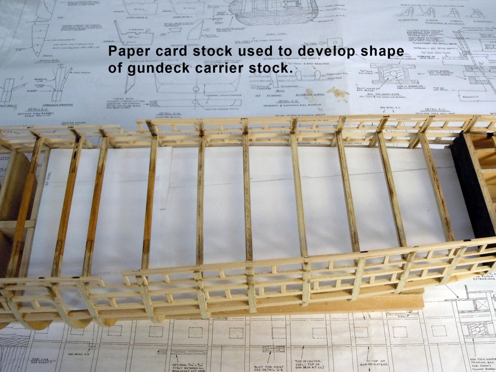
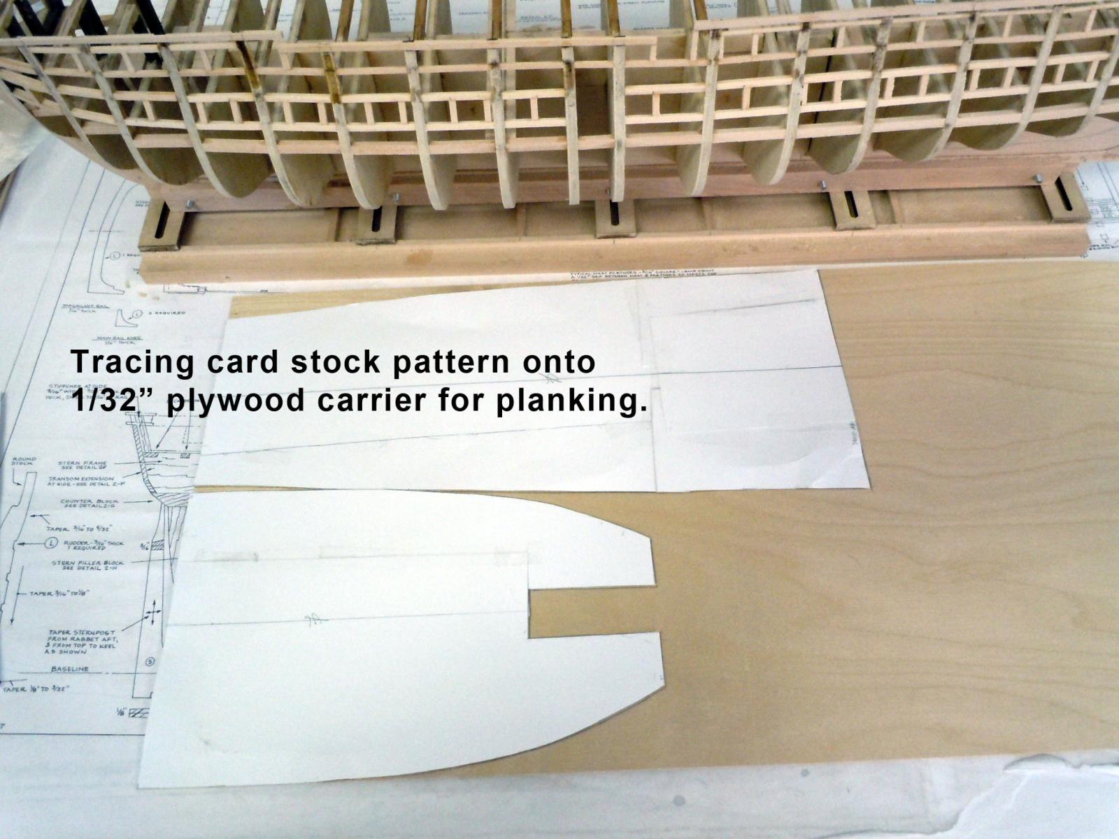
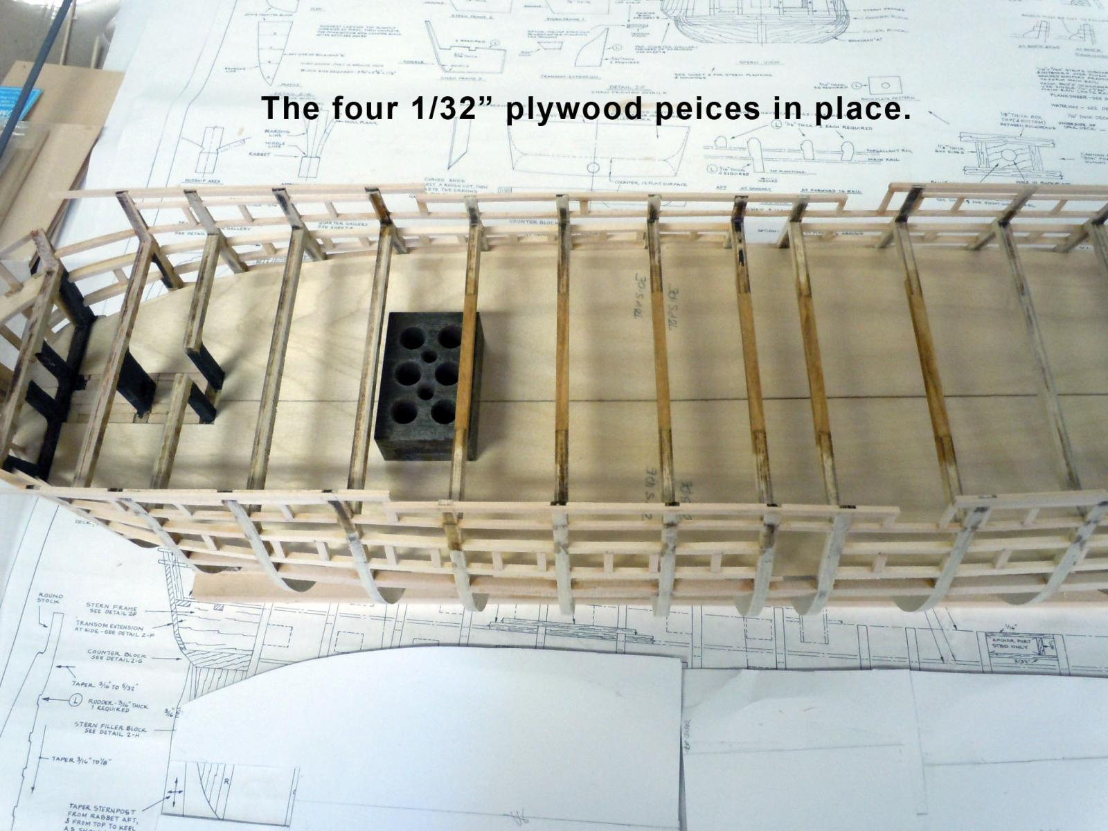
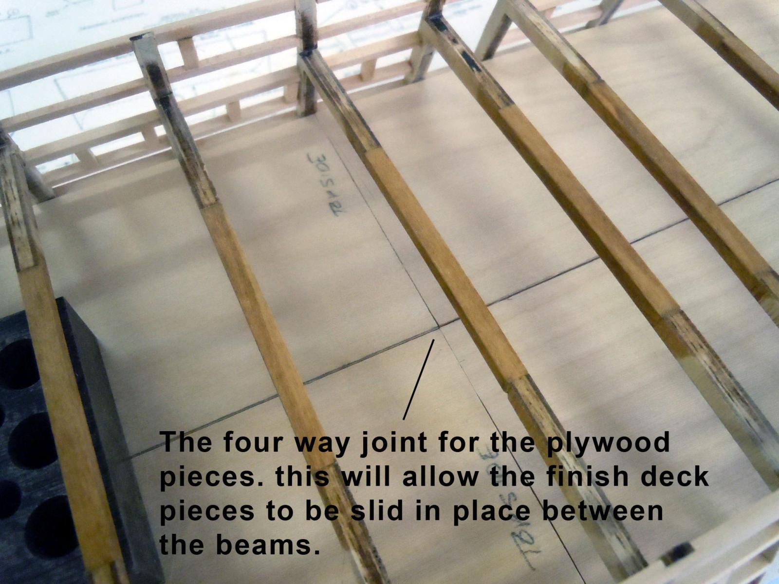
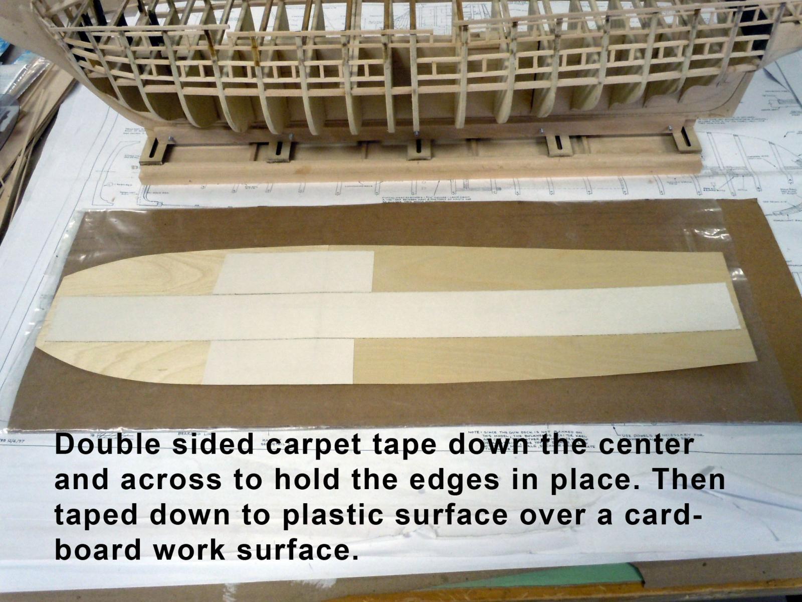
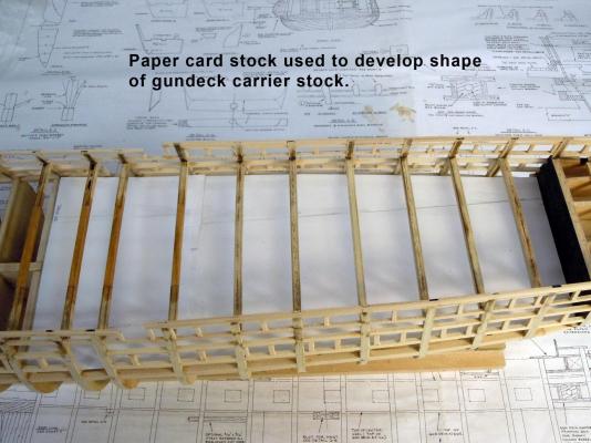
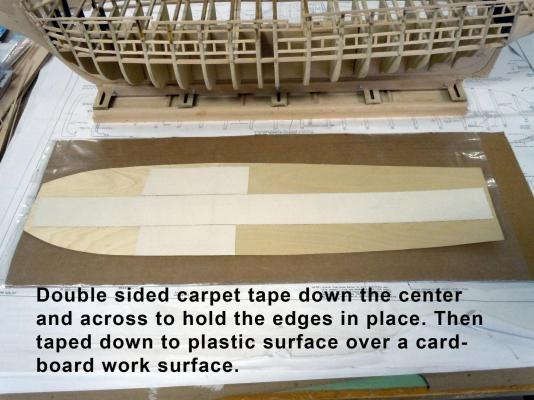
George, we will see I sent John an email showing the picture and needing another 36 or so; but I also asked for a quote for 90 strips for the gun deck. We will see. I am a little hesitant to start without having all in hand. I have the gundeck carrier completed and ready for planking. First I created a pattern using paper card stock, my sophisticated CAD system (Cardboard Aided Design). I then transferred the pattern to 1/32" plywood which will be the carrier for the deck planking. I then final fitted the plywood halves in place. Once fitted I then cut them down the centerline so that there will be four sections to the deck that will slip between the beams in place. This shows the four way joint that will be below a beam. Next I carpet taped the underside down the tight joint and taped it to a plastic covered cardboard work surface. I intend to us blackened white glue to represent the caulk lines. Now I will look around to see what I can do until the order comes from ME.


-
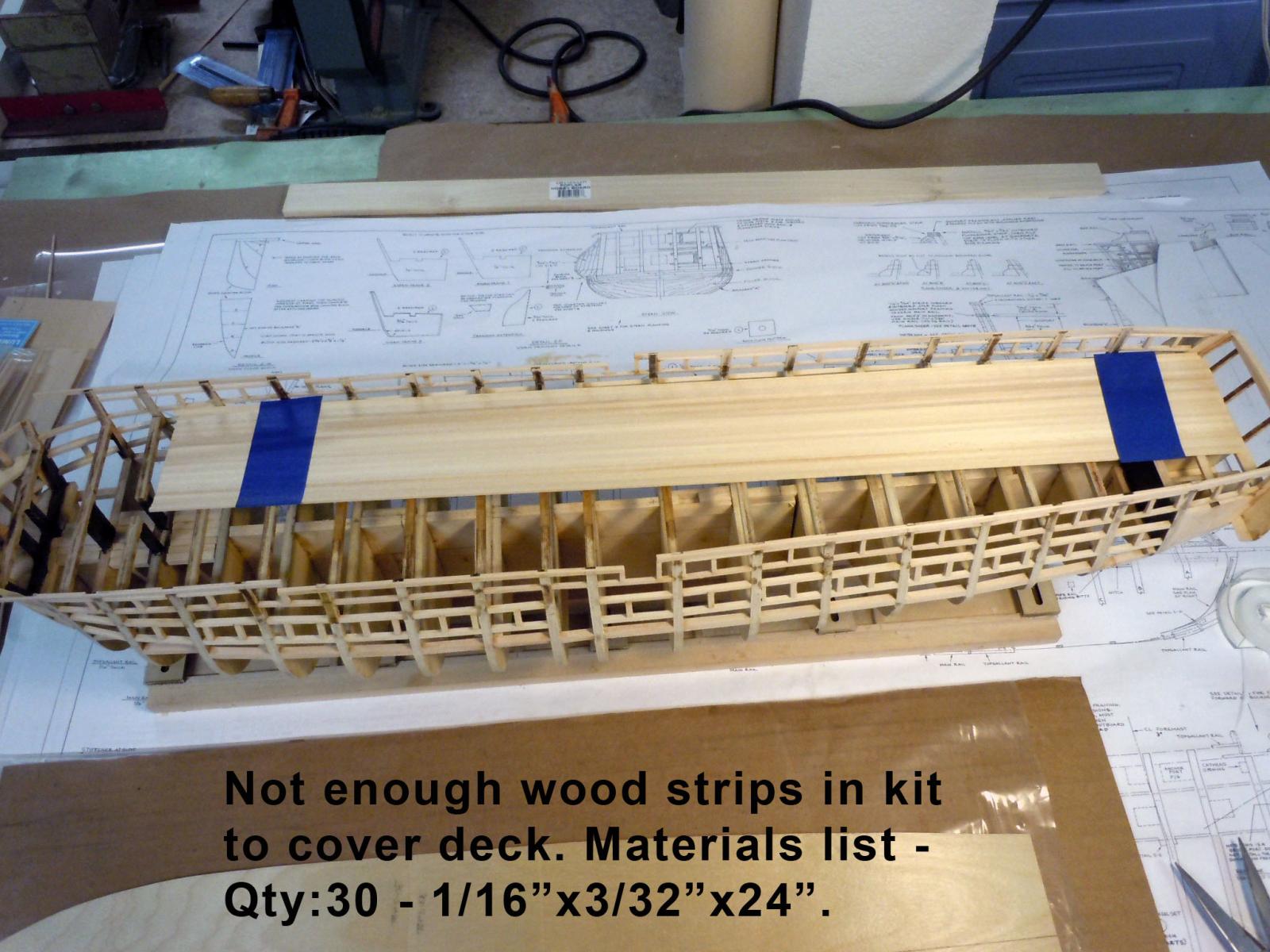
George hopefully the dimensions of the plans are accurate because that is what I used. My next "what the heck?" Not enough wood strips to do the deck. Materials list says 30 -1/16" x 3/32" x 24". Only about half of what is really needed. See attachment. Has anybody else have this issue and how was it resolved. I will be emailing ME for more.

-
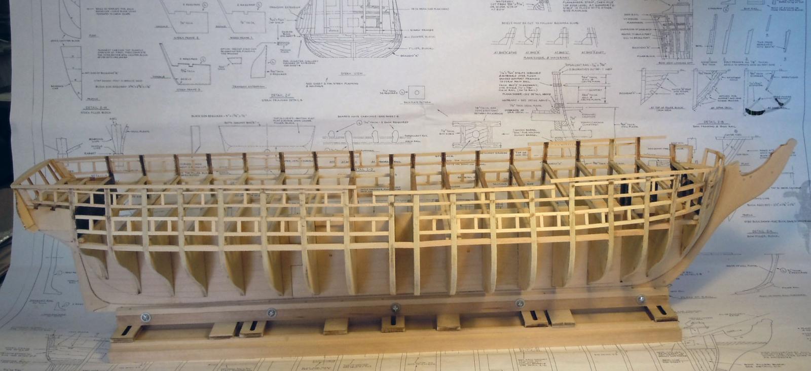
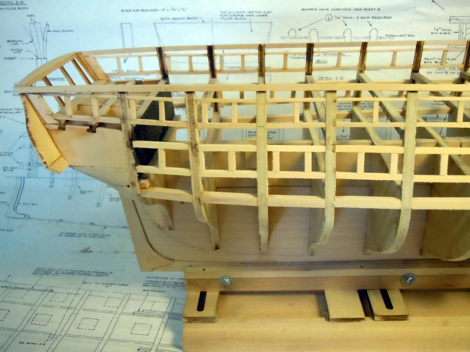
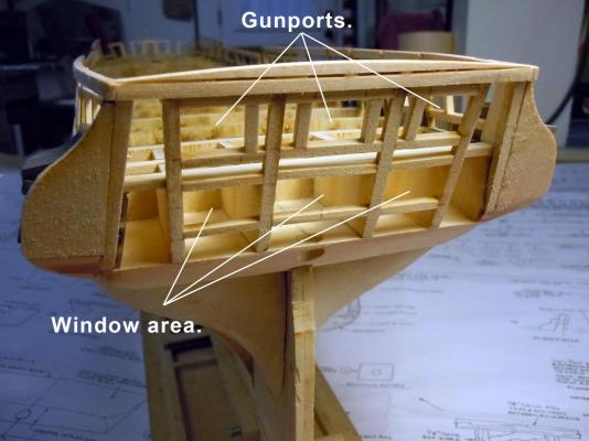
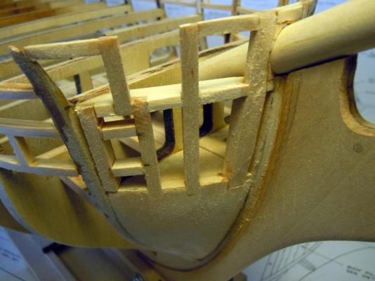
I moved on to the gunports, logic being the side of the hull being much stronger to work around while adding the decks. Here is an overall of all the starboard gunports in place and the entire hull sanded smooth ready for planking later on. Here is the stern section where filler blocks still need to be added. I also fitted the bowsprit and filled around the area that penetrates the hull. Here is a close up of the bow section. Now to finish sanding the post side of the hull to smooth out the gunports. Then onto the gundeck planking which I intend to do the same way as I did the Niagara deck only in two sections that will be inserted at the widest station bulkhead "H".


-
Geoff, thanks for the heads up! I think I will make a cradle for it much like I did for the Niagara. This one will go to my son who lives in New York City; but will go to his house at the end of Long Island. Thus it will have to survive a cross country drive and I think the cradle will be stronger and easier to cushion.
-
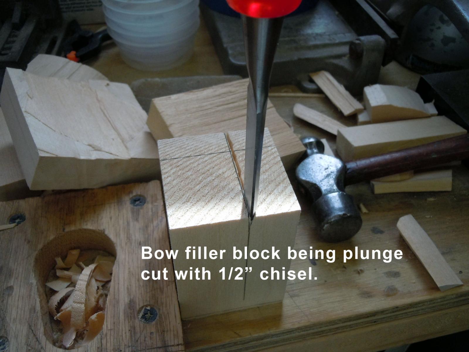
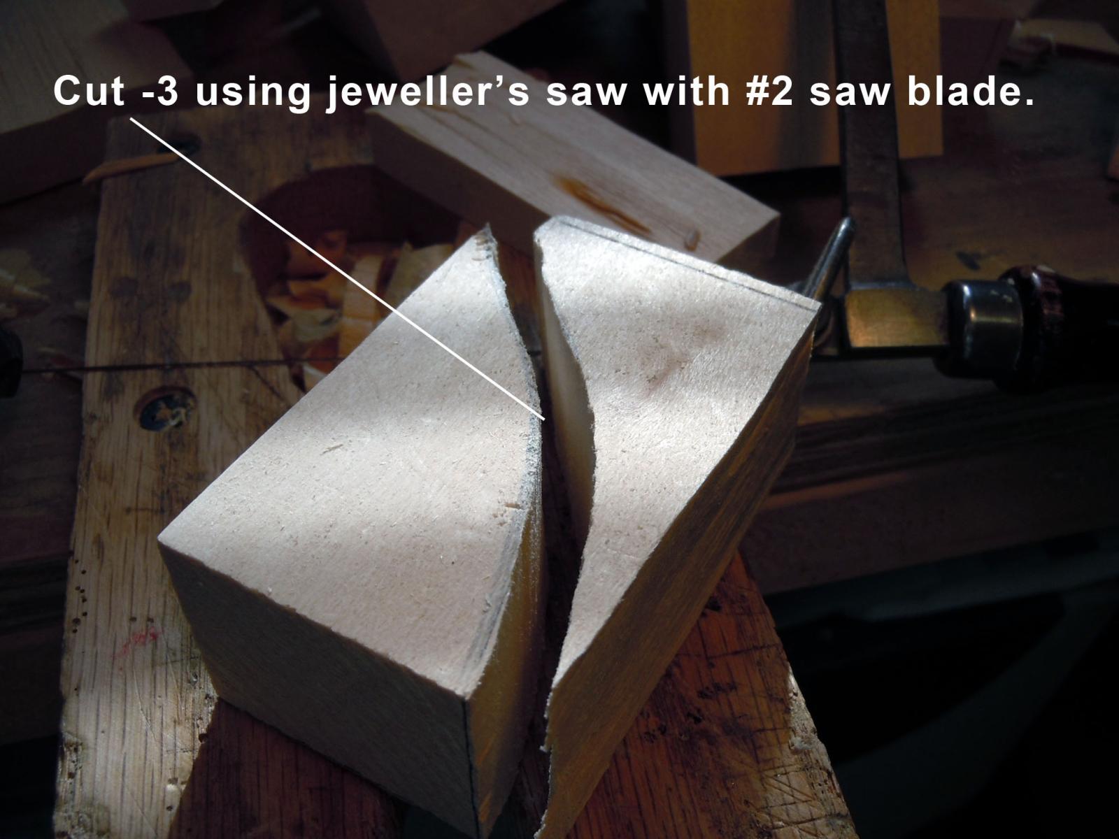
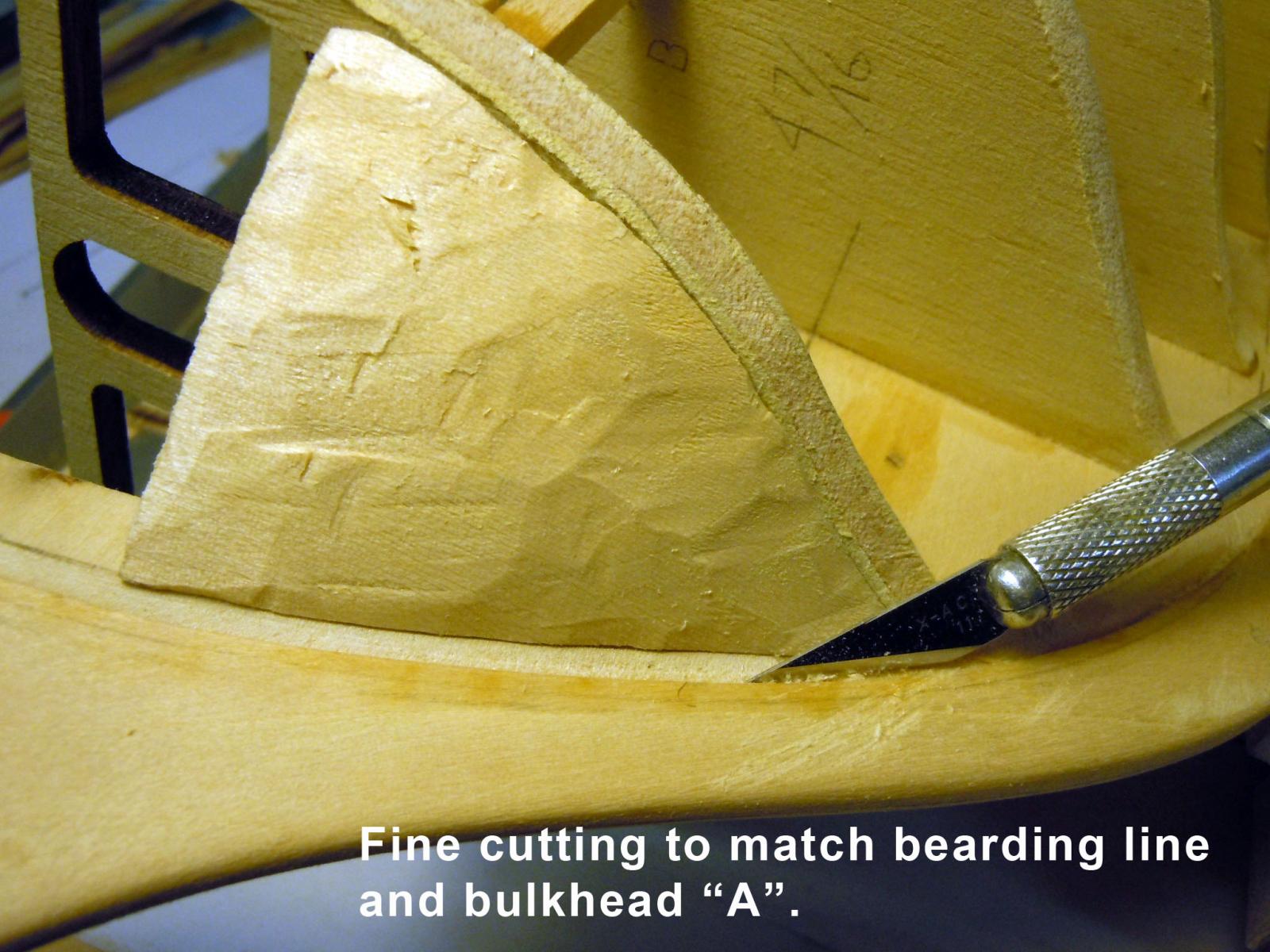
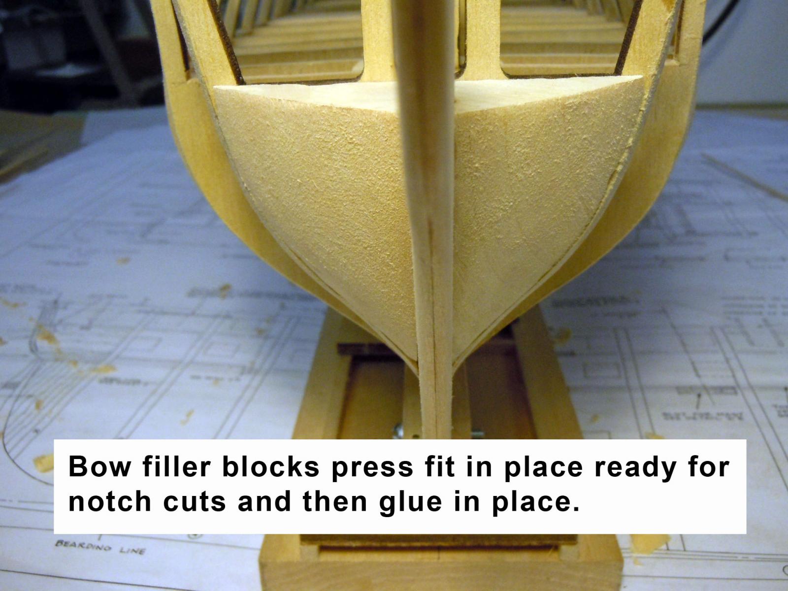
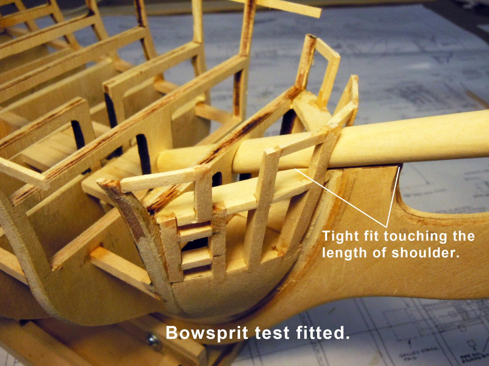
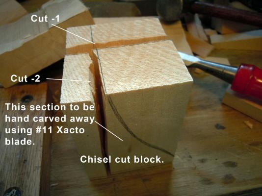
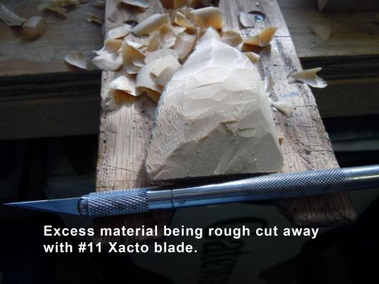
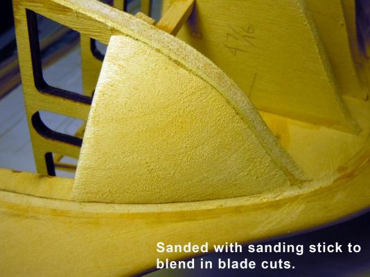
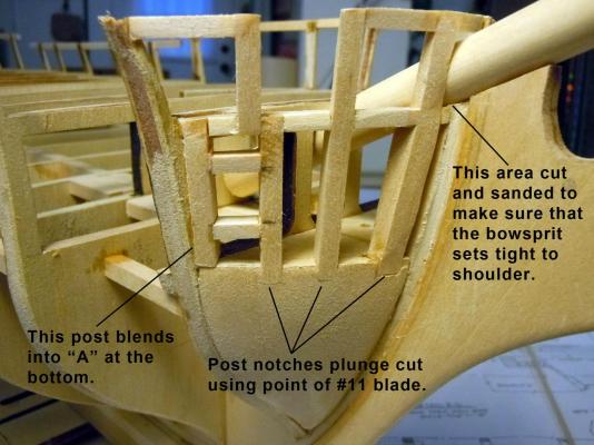
John, thanks for the compliment about carving. I moved on to the bow filler blocks along with the bow posts. I am showing a sequence of carving the blocks with no power equipment since I have neither bandsaw or sanders. First I used a 1/2" sharp chisel to rough cut the blocks down to size needed with drawn on profiles as guides. Once the blocks were cut I then used the jeweler's saw to cut the curve. I recommend using the bench pin to cut on. Next again working on the bench pin I rough cut away the excess material using a new sharp #11 blade. Next I set the block in place and fine tuned the fit now using the beading line and bulkhead as guides. The block was then sanded smooth to eliminate the blade cuts. Tip: I found a selection of finger nail files at the drug store that are great and more cost effective as sanding sticks. The orange course one works best. This shows both blocks held in place by a tight fit vacuum (no glue). Once satisfied with the blocks I cut and fitted the posts and braces to finish off the bow structure. I cut the notches by plunge cutting first the top and then the bottom at 90 degress using the straight back of the blade as reference. Once the plunge cuts were done the two sides were cut resulting on the notch for the post. Once the structure was complete I test fitted the bowsprit and cut and sanded the shoulder to have the bowsprit fitting tight on the shoulder. Here is a view looking down on the bow structure. I hope this explanation helps sort out some of the confusion that may be caused by the plans.


-
Markku, Your build is looking great and I will be following in your footsteps with my build. Keep up the great work you are doing!
-
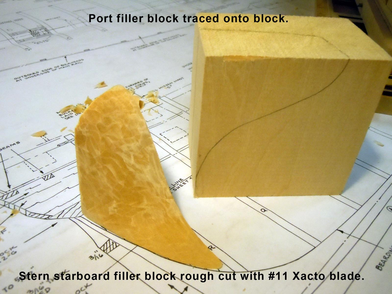
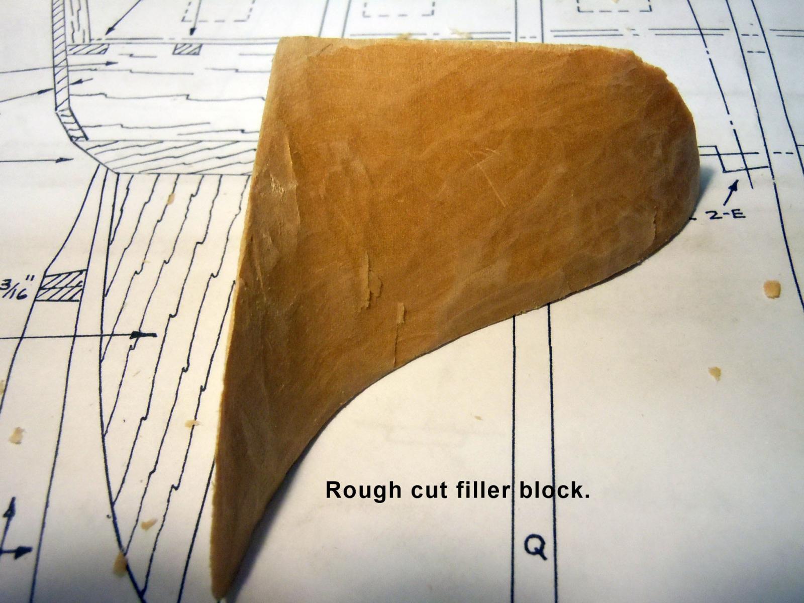
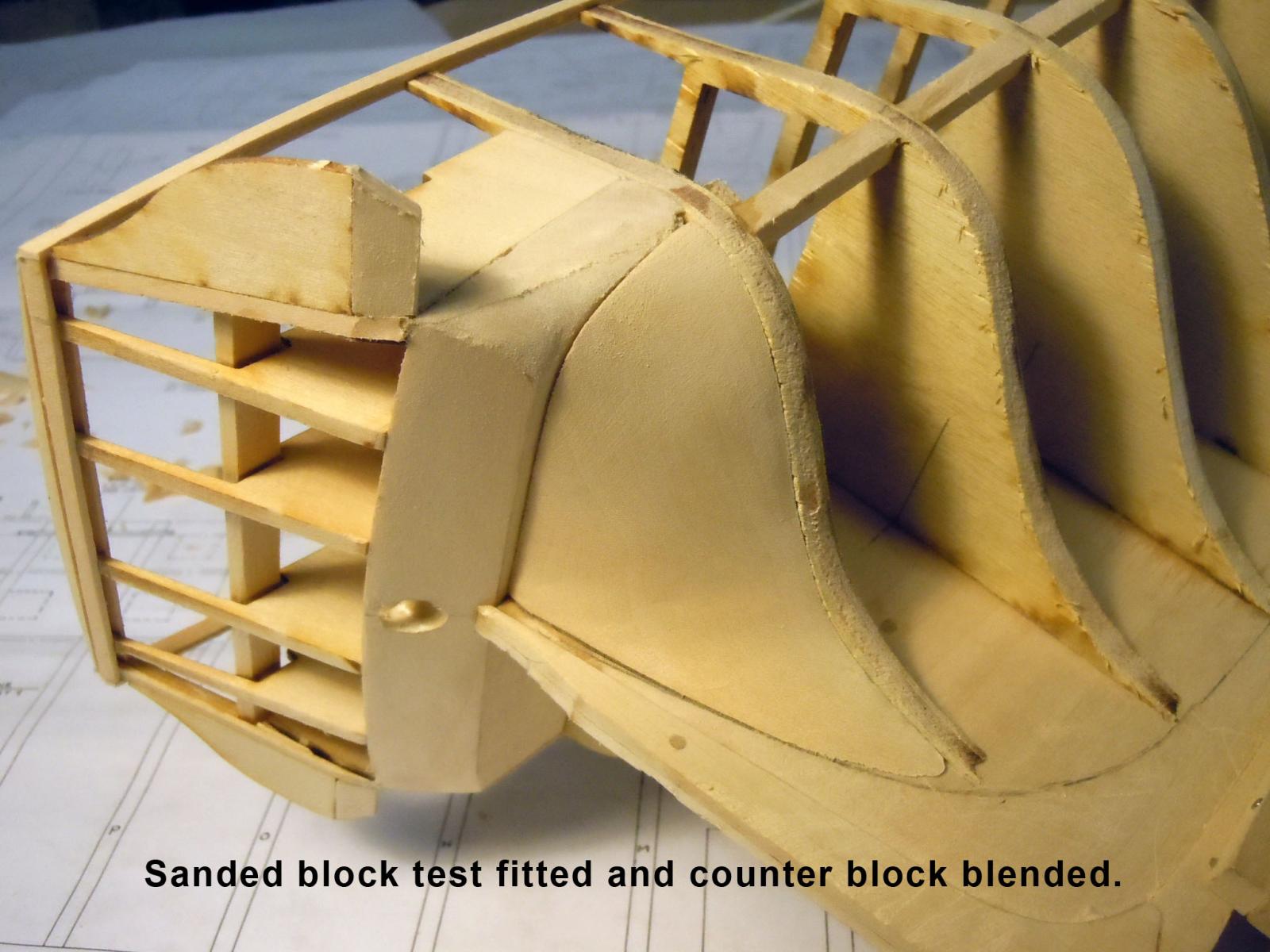
Tom, Geoff thanks for your encouragement. I moved onto the stern filler blocks which not having a bandsaw was a slow process of sawing by hand. Once cut out I carved away using my trusty #11 Xacto blade and rough cut the shape. Here are a couple of views of the rough cut. This shows the starboard block on the plan with the port side still trapped in the wood block. A rear view. Here I test fitted the sanded block in place and blended in the counter block. I will wait until the port block is cut before gluing in place.


-
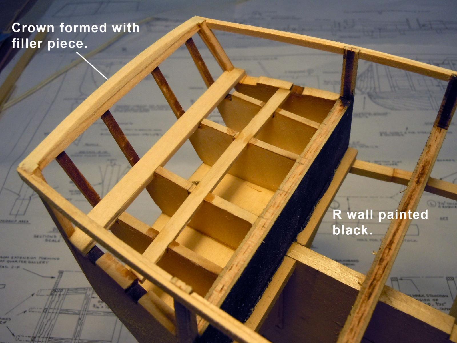
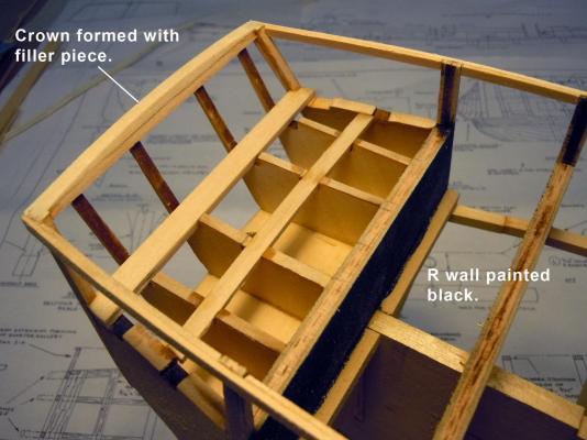
Geoff, Tom, thank you for the advice! Here is my solution using some of the kit parts with new corners. I also reinforced the tops of the bulkheads with an outboard plank since they are sensitive to breaking off. I also added the crown to the top of the transom as well. Next I will work on the filler blocks. Jud good thought but look at the detail on the plan sheet in the background of the picture and you can see that it is not parallel to the keel.
-
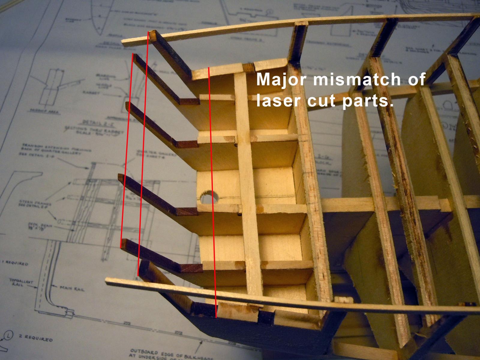
My first "What the heck" major mismatch of laser cut parts. Not sure how this setup could miss so bad but will start to fix. I hope this is the only one; but I am always the optimist. I will break and adjust the two outboard corners since they will be covered with planking. The thinner center ones can be brought into alignment with planking.

-
Tom, thanks for the feed back! Also is it worth it to purchase the book you have? I see it is available from amazon for about $30.
-
Tom, thanks this technique comes in handy at times. I have a question for you. In looking at your build it appears that in the center opening that the kit beams do not align with the beams you have installed or the openings for the grate frames; I am assuming that you referenced the book for accuracy and that your layout is correct versus the kit deck beams? I really would appreciate your feed back and if possible the dimensions of what the beams should be. Thank you in advance. Ken
-
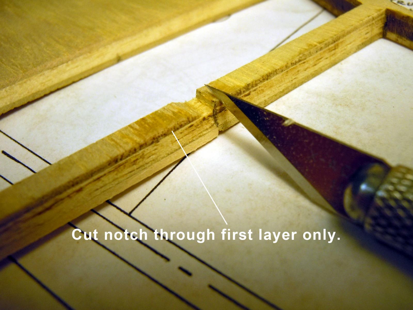
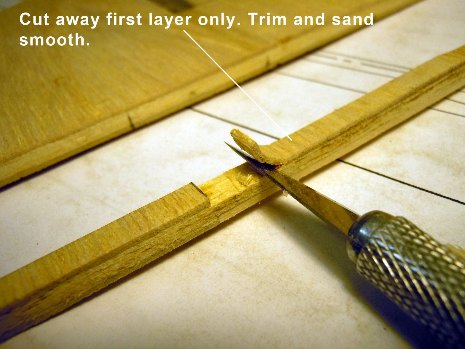
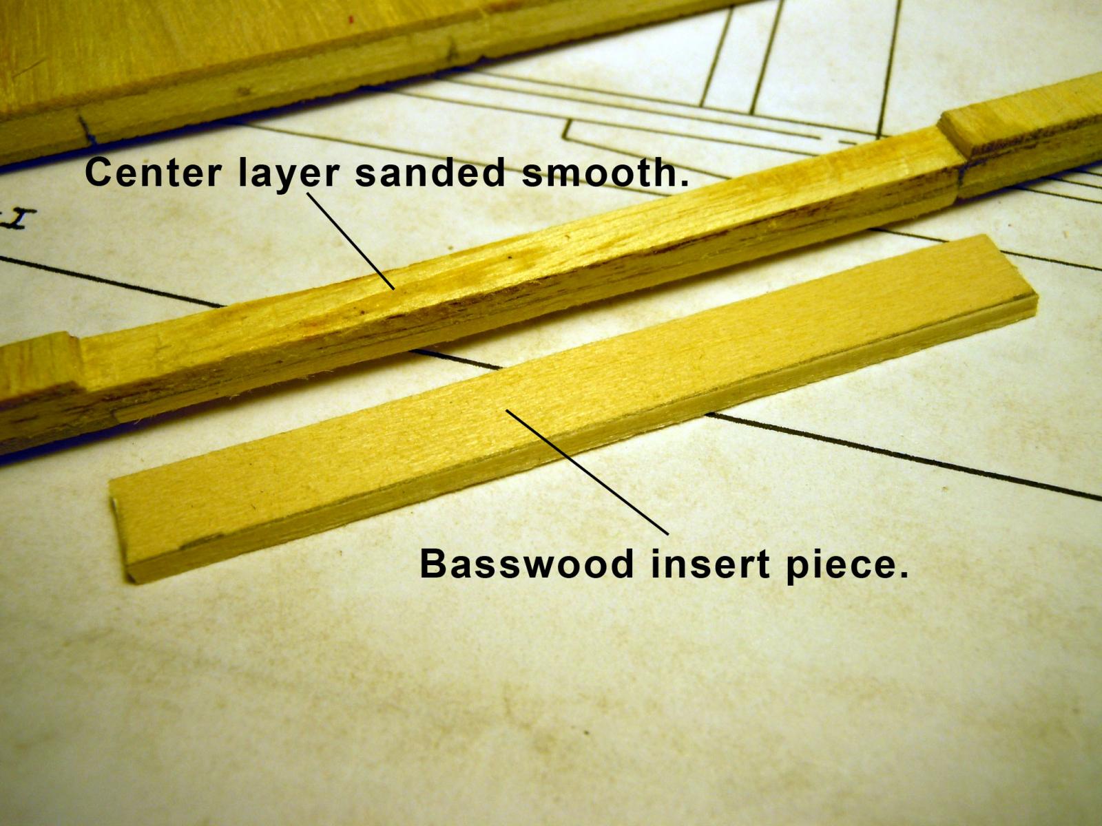
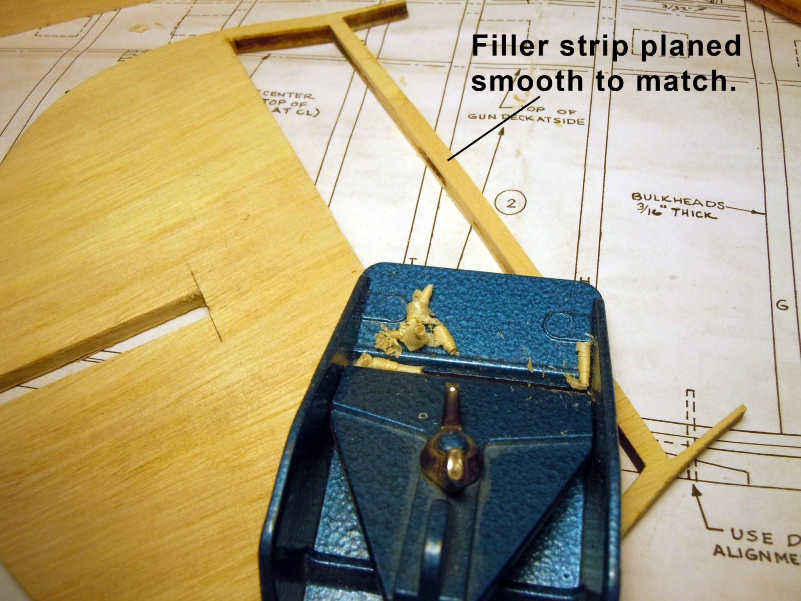
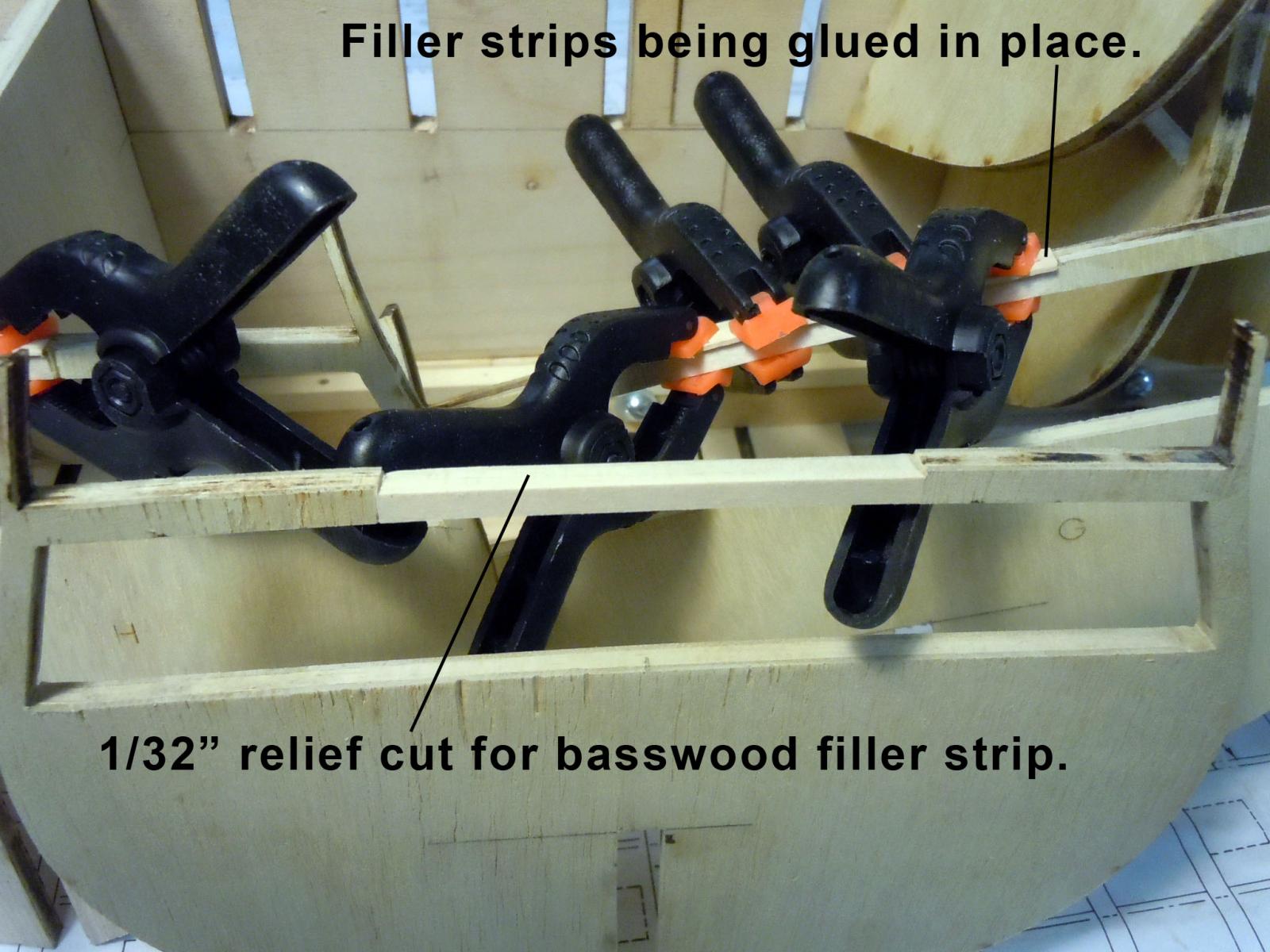
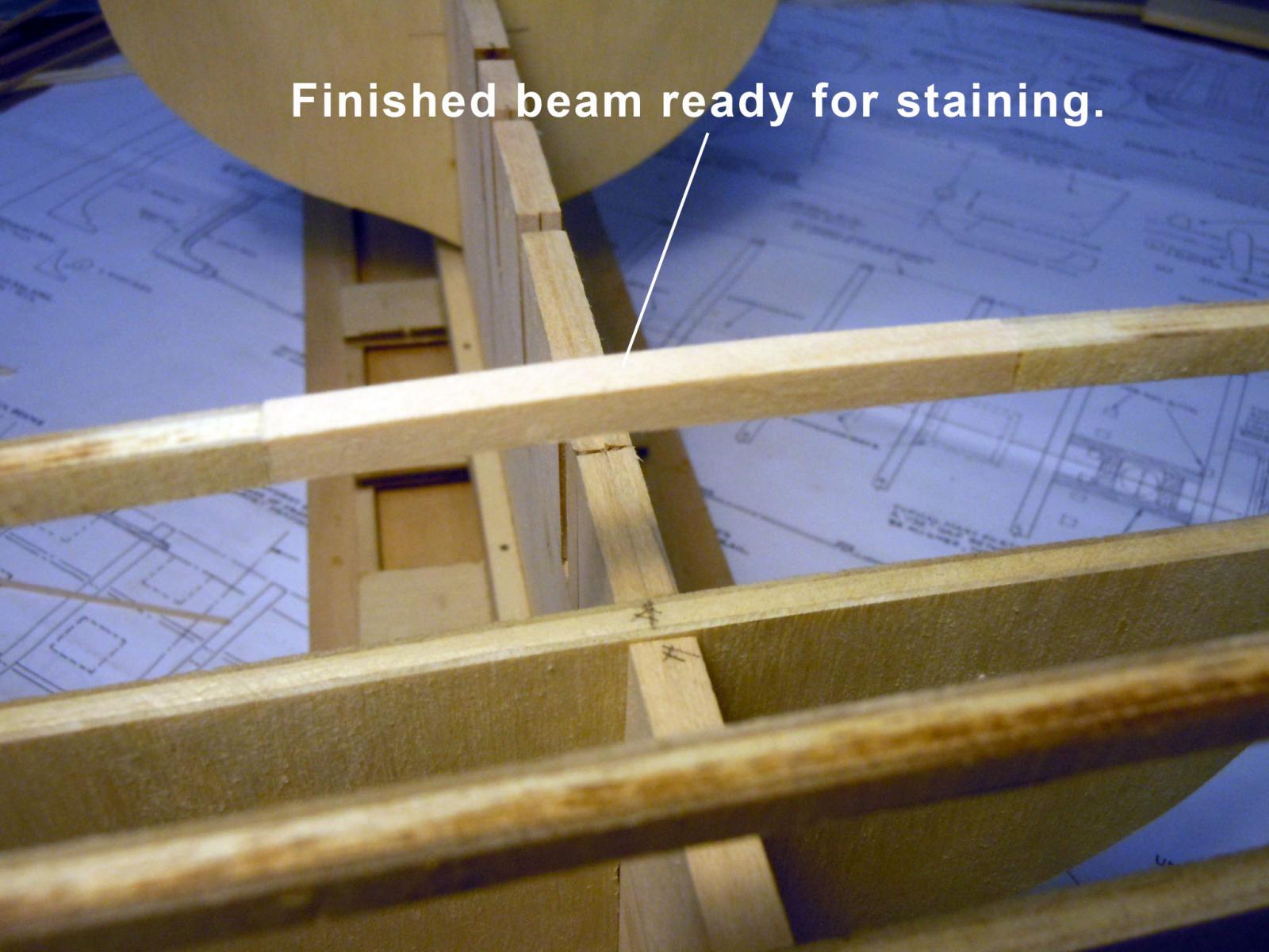
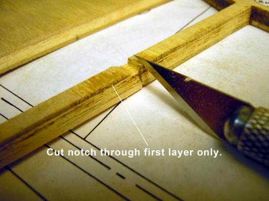
In checking around I saw the need for replacing the center sections of the beams in the area of main hatch where the pinnace will rest. I am thinking that if possible this area will be able to be lifted to see the gundeck. I did not wish to cutaway the plywood beams and loose strength and geometry so I fell back on a technique from my airplane building days of delaminating plywood. The kit plywood is a three layer lamination. First I marked off on the two sides the length from the centerline that will be seen when hatch area is removed. Then I cut a vertical cut at each end to the depth of the first layer on one side. Next I cut a notch back to the vertical cuts and by carefully twisting the blade removed the first layer material on the side at each end. Then carefully inserting the blade and cut away the first layer of plywood. Once cut away the area was sanded smooth and level. I then glued a 1/16" thick basswood strip into the gap and let set. Once both sides were laminated with basswood strips and the glue completely set I used a small plane to remove excess material down to the plywood surface. Then finish sanded the surfaces. Next the top of the beam was notched down 1/32" using a #11 xacto blade carefully maintaining the arc of the beam. Once cut a basswood strip was glued in place. When the glue was completely set the excess material on the edges was planed away and sanded smooth. Here is a basswood claded center section of the beam ready for staining. This process went fairly quickly since there was a continuous operation of working six bulwarks. Next to look to see what else can be done before gluing the bulwarks in place.


-
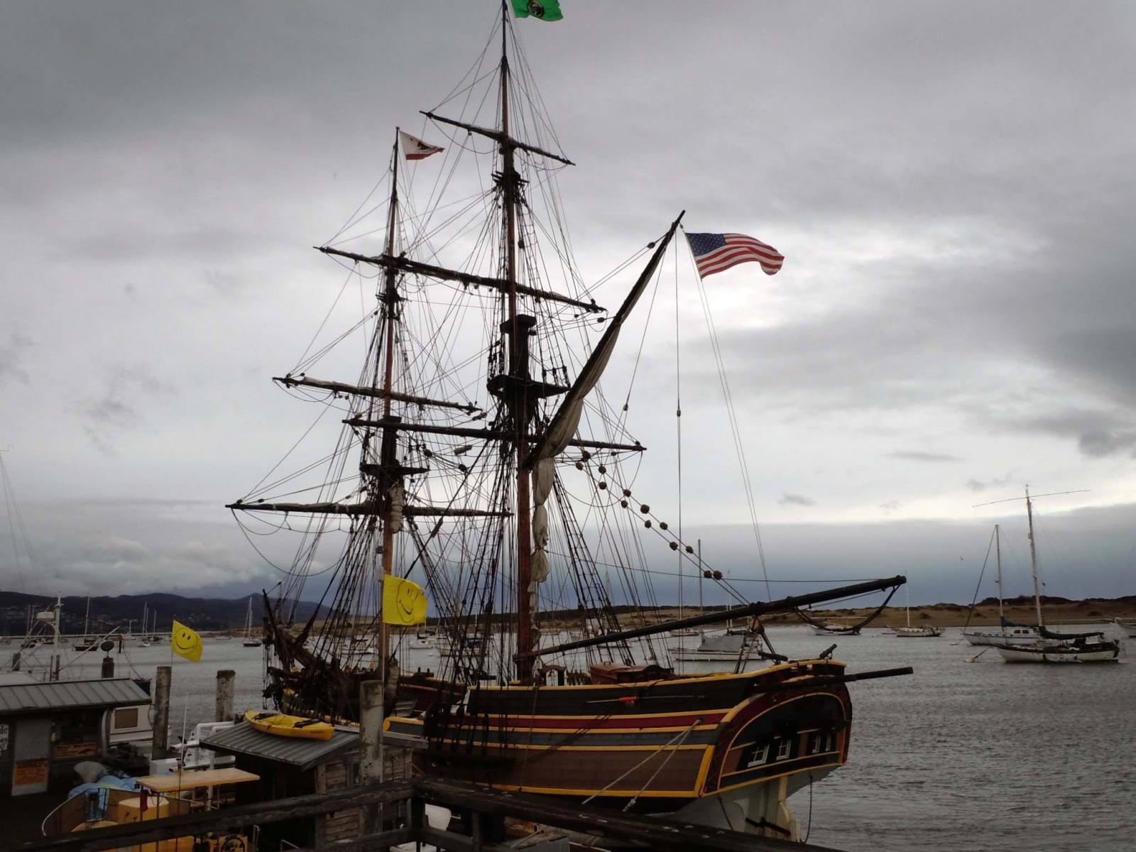
Spent the afternoon on a two hour cruise on the Lady Washington. I now have a much better understanding of the dynamics of the rigging having seen the crew set sails, work them and then stow them. I took 147 photos of details of everything; enough to scratch build if I choose to. The cruise was fantastic once we cleared the harbor and got into the open sea with 8-12 swells. Loved watching the bow rise and fall and the ship roll; at one point almost at a 45 degree angle. I was on the rear quarter deck near the tiller and had a great chat with the captain and listen to him call out maneuvers for the crew. This ship is rigged very much like the Niagara and as I looked around recognized most everything. This ship was the fast British ship in the movie "Pirates of the Caribbean". This was just a great personal learning experience. Here she is heading out of the harbor at Morro Bay.

-
Geoff Great work! I will checking in on your progress I am just starting my Constitution build.
-
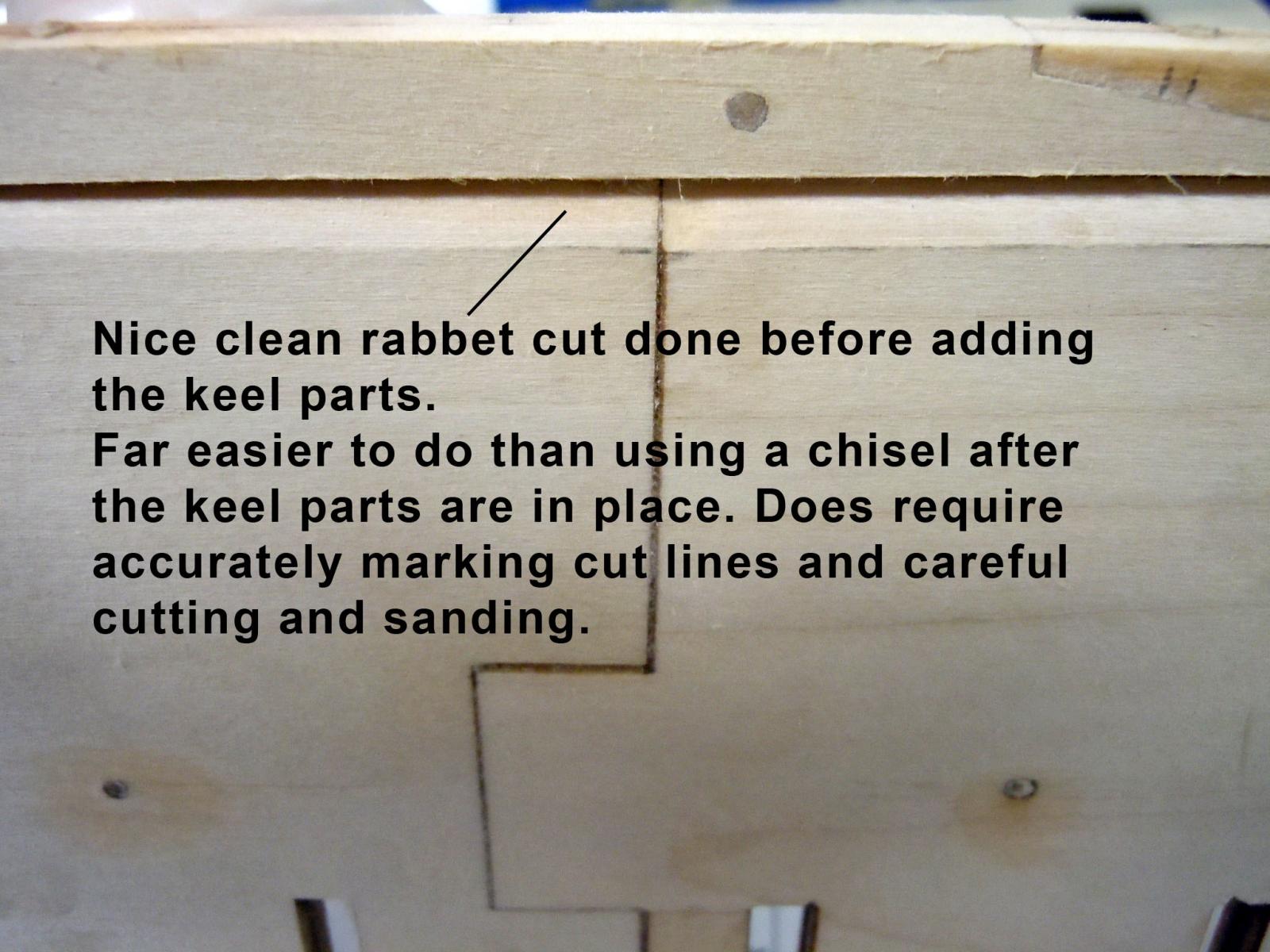
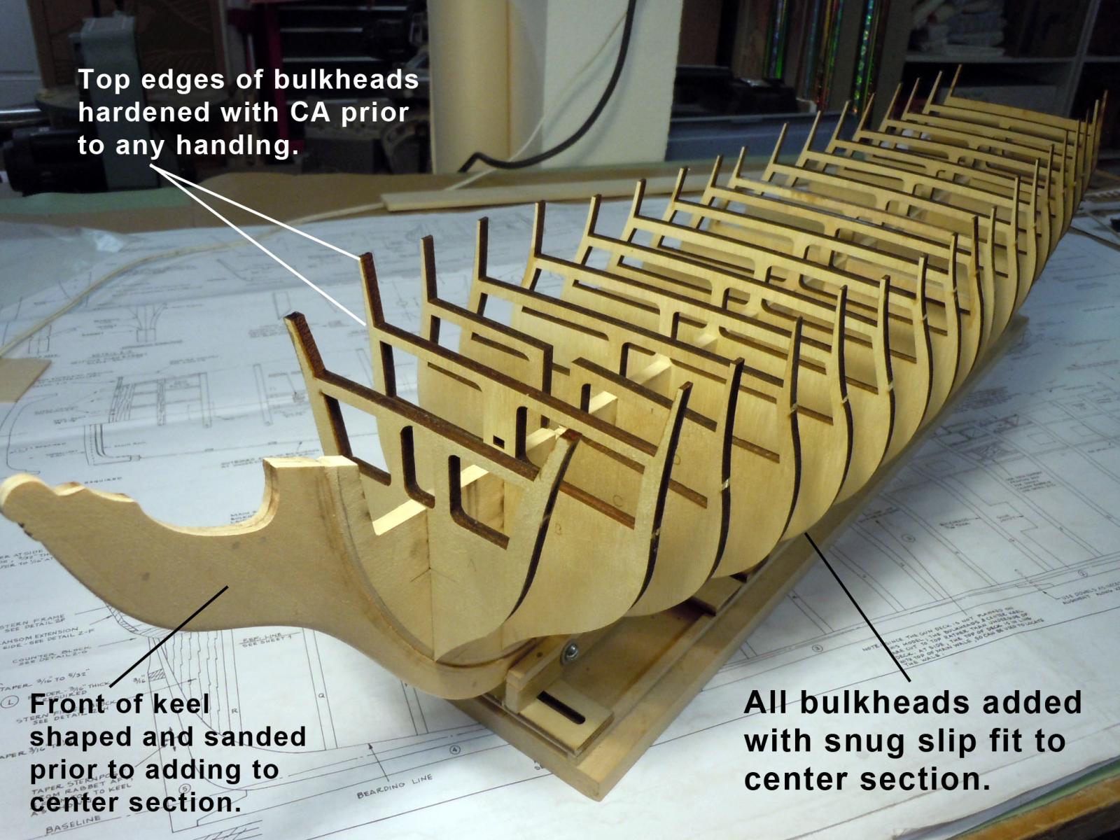
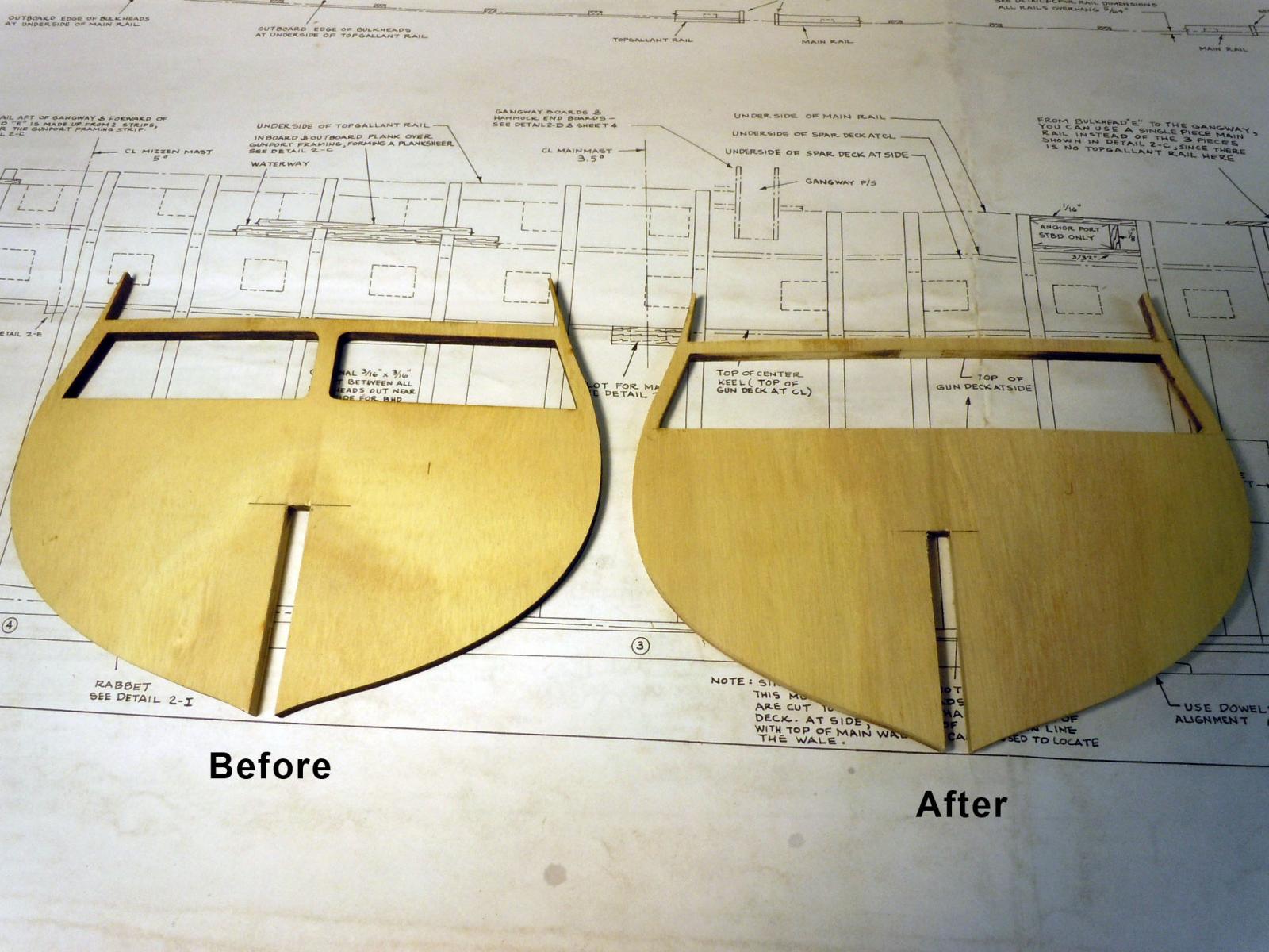
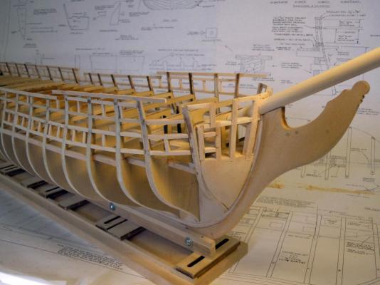
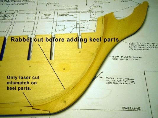
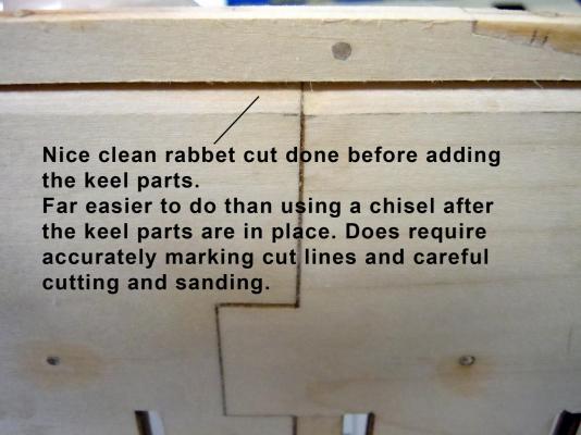
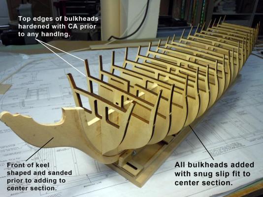
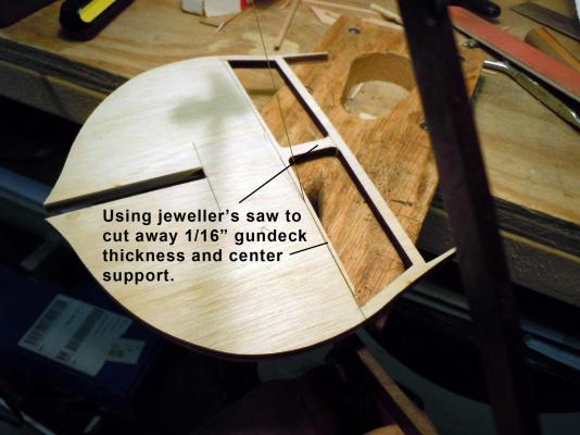
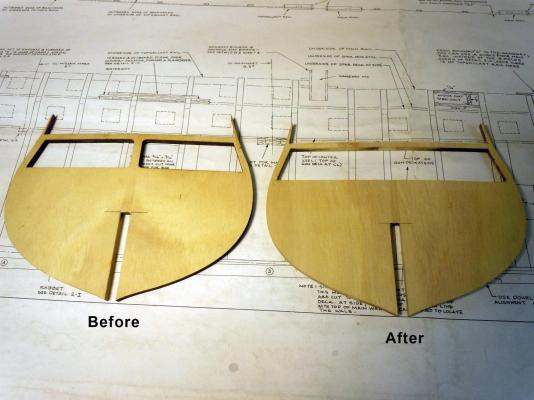
A lesson learned from the Niagara build was to do the rabbet cut on the center section prior to adding the keel parts. I carefully marked the cut to lines and then proceeded to cut and sand both sides. I also cut,tapered and sanded the bow keel part before gluing to the center section. The only minor mismatch was at the bow end. Here is a close up of the rabbet cut once the keel was added. Next I moved onto the bulkheads and I started in the center and moved fore and aft sanding the slots in the center section and bulkheads to achieve a snug press fit. TIP: Once the bulkheads were removed from their carrier I hardened the thin top sides with CA because they break off very easy. Once all bulkheads were in place I marked the area needed to be removed for the gundeck planking and the center support. I used a jeweler's saw to remove the needed material. Here is a before and after showing the difference. Here the difference can be seen with the bulkheads in place. Now back to finishing up the rest of the bulkheads and then trimming the center section.

-
Greg, had a great time with them and if I had known how much fun grand kids were I would have had them first. I have purchased a ticket for a two hour cruise on Sunday>
-
Just back from visiting what may be my first scratch build if I live long enough. The Lady Washington. It was a quick trip with the grand kids and will go back for photo details. I was able to buy two pages of basic plans. They say this was the first American built brig to round the horn to San Francisco. Here I am with the grand daughters. The Brig Niagara is now berthed at there house.


-
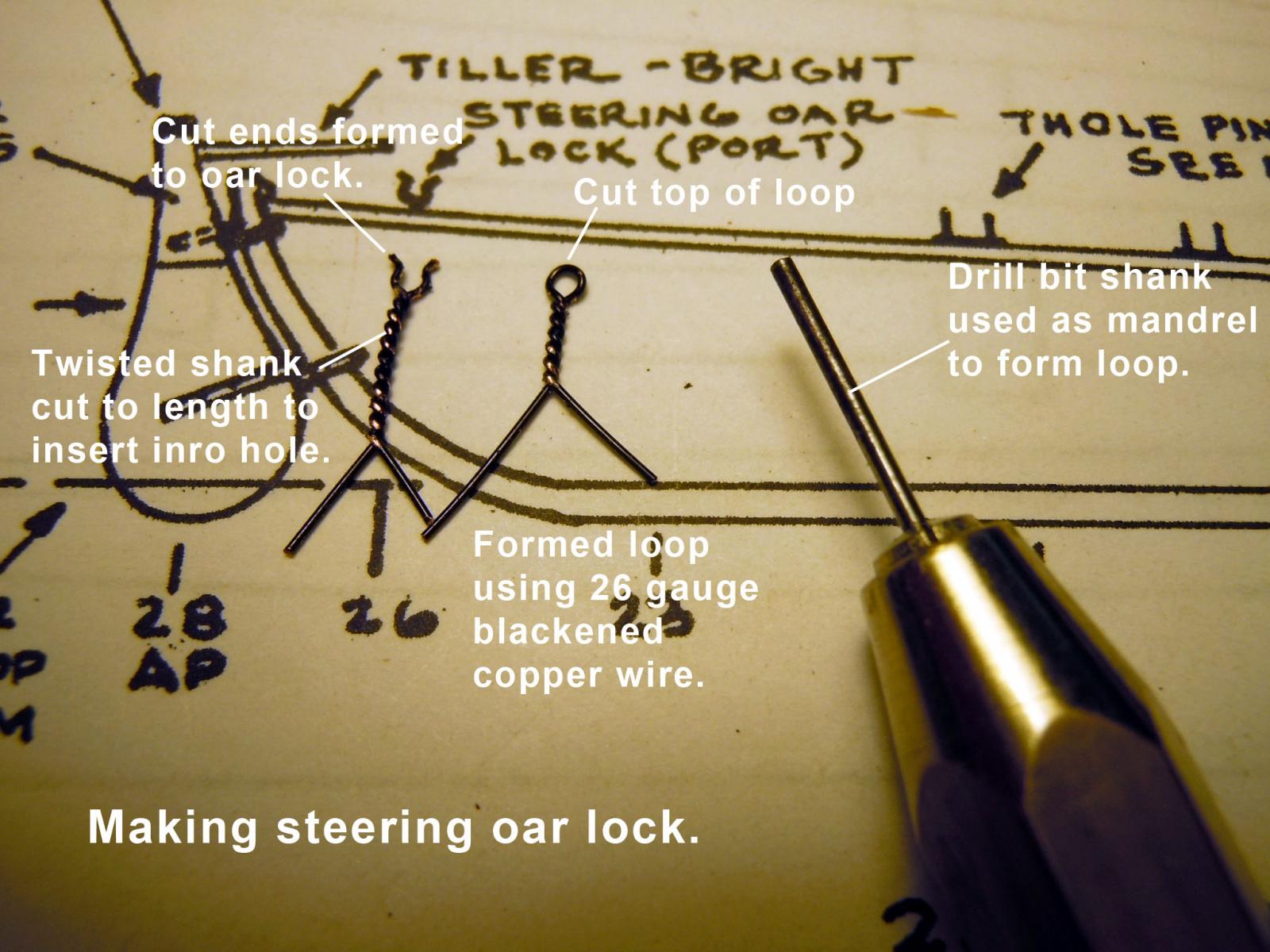
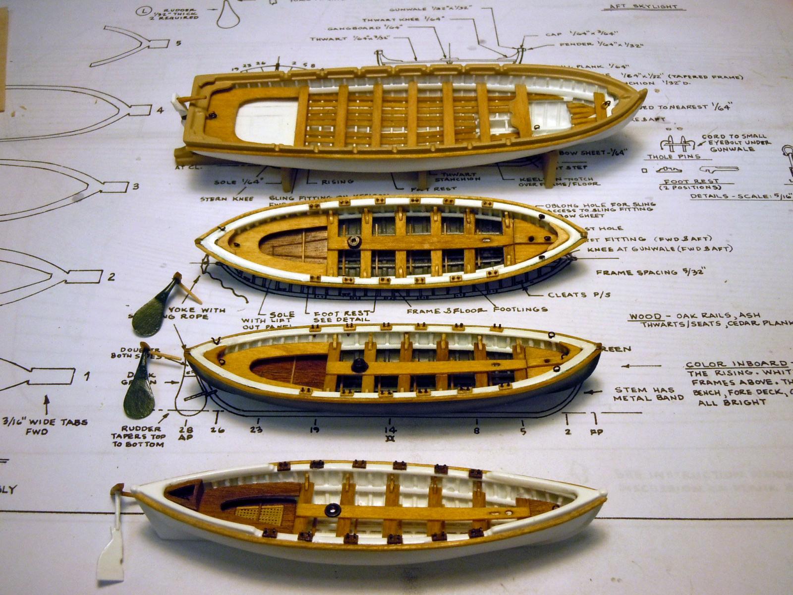
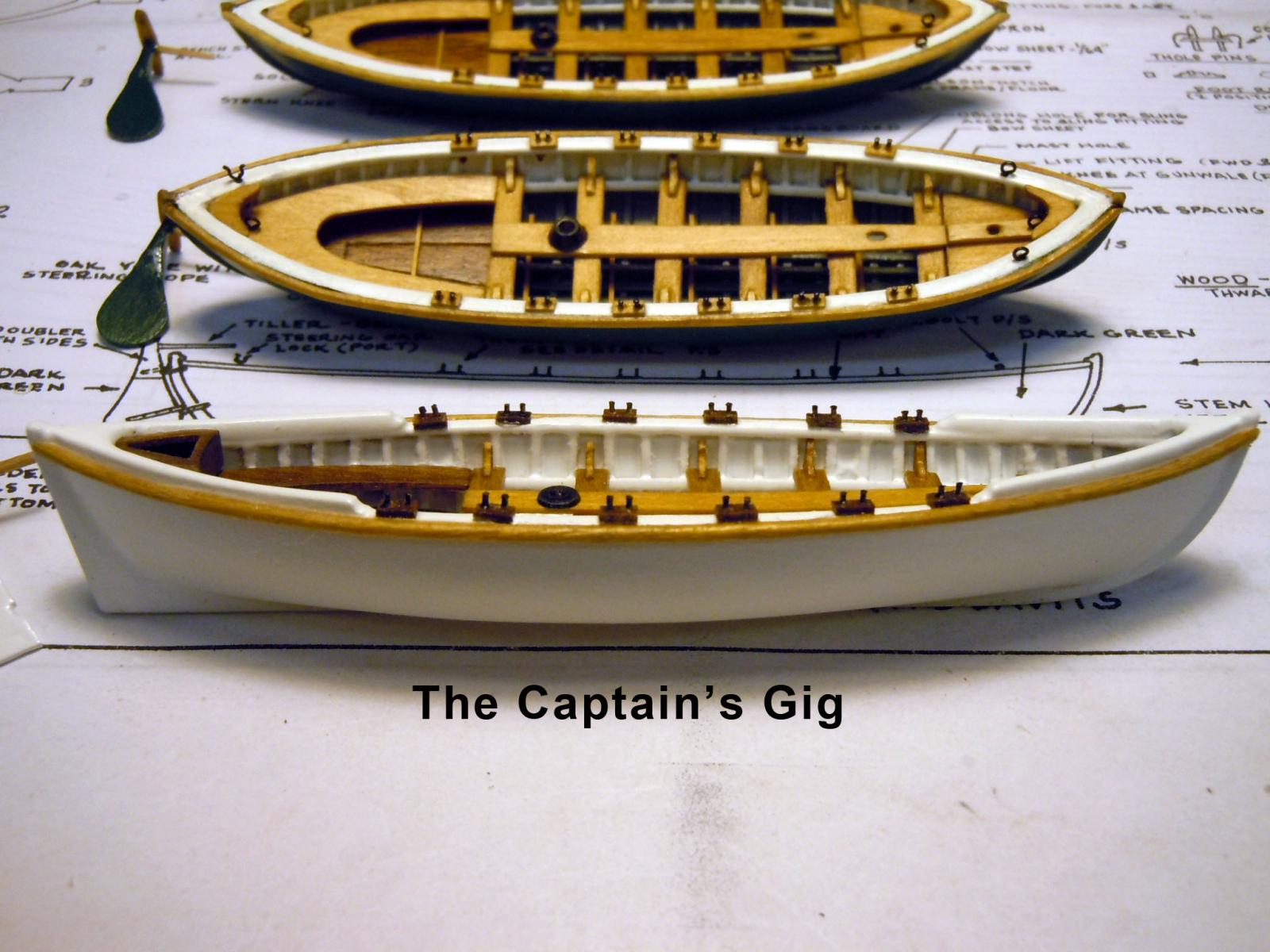
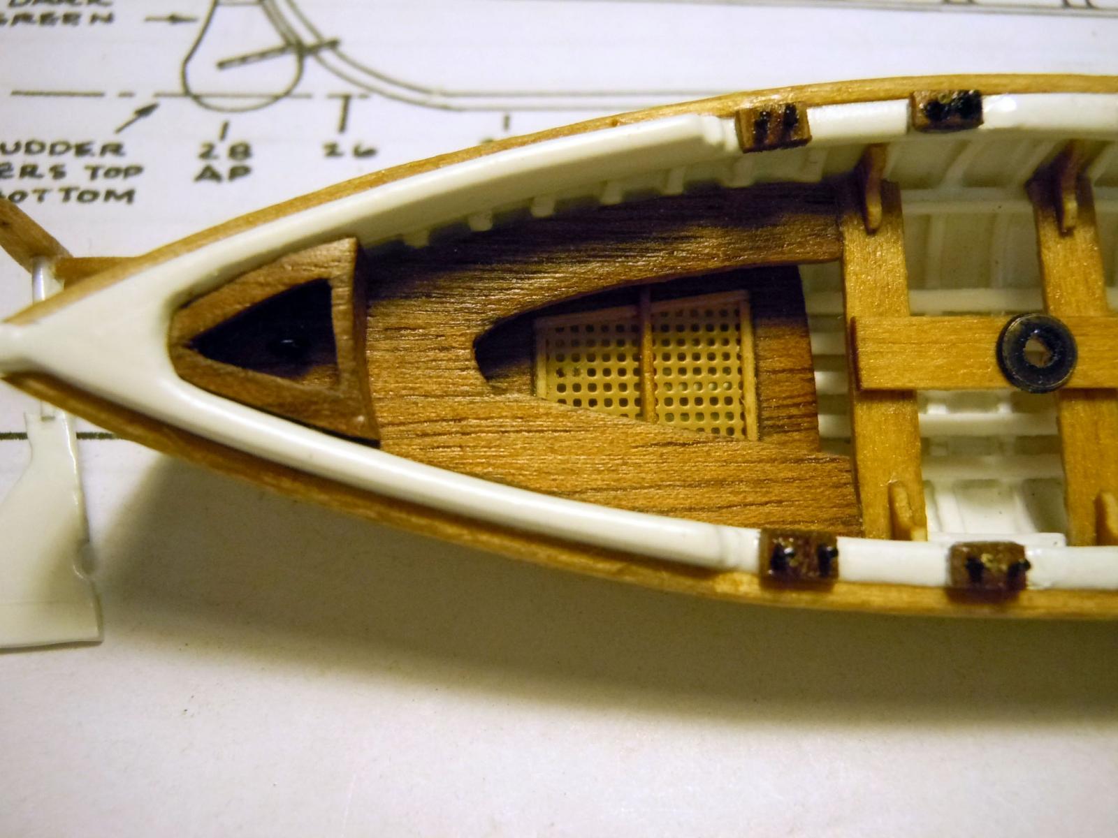
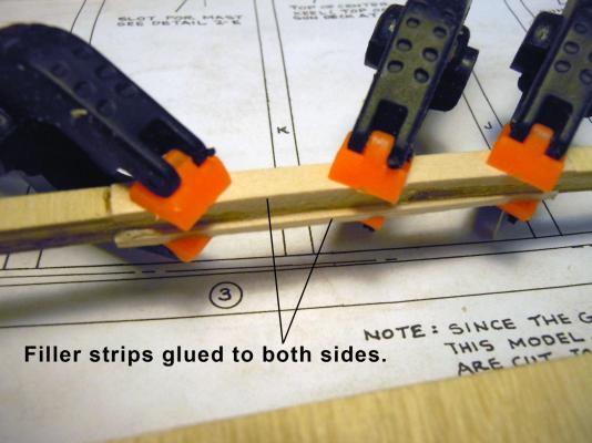
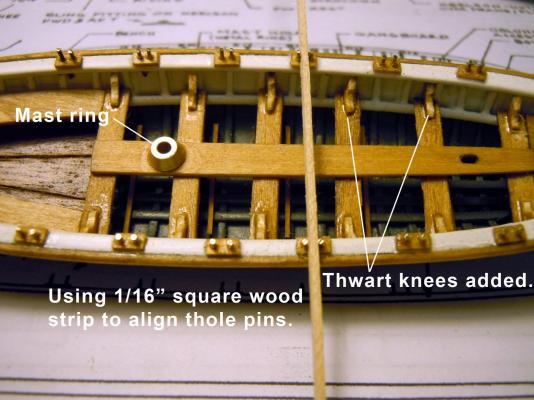
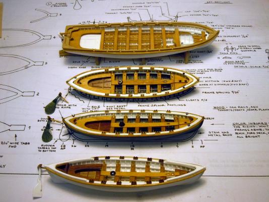
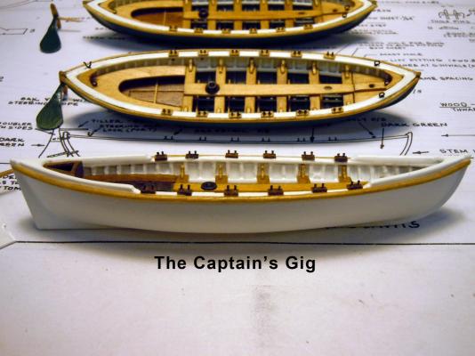
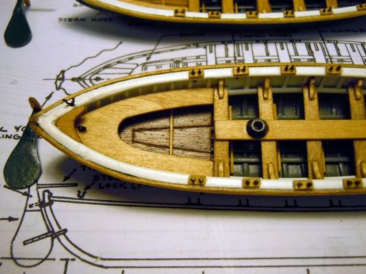
Just finishing up the four small boats and thought I would share a couple of details on them and how I made them. First is the steering oar lock that is located on the stern area port side on the whale boats. I formed a wire loop using the blackened 26 gauge copper wire using a drill bit shaft as a mandrel. I then cut the top of the loop and very carefully formed the needed bends with small needle nose pliers. Next the thole pins were added into small pieces on the top of the rail. I then used a 1/16" square wood strip as a gauge to cut and file them evenly. The mast rings were turned using brass rod drilled and cut with the angle needed. Here is an overview of the boats with tillers off to the side. I still need to add the hinge hardware which I will do while waiting for the glue to dry on the center keel. Following are a side view of the Captain's gig which is 4.5" long and a couple of closeups The rear grate is photo etched part. Now back to the center keel assembly. On this build I will cut the rabbet cut prior to adding the bottom keel parts which should save considerable time. We will see.


-
George, Thanks! I am a great deal more knowledgeable now about ship building than when I started the Niagara. This will be a slower build with more attention to "ship" details. I also ordered the 30 cannon set to build out the gun deck and will be sticking my nose into other builds to learn more regarding the gun deck. This build will go to my son who lives in NYC and has a house at the end of Long Island. The Niagara was transferred yesterday to its new berth in my daughter's house. Her husband is a container ship Captain for Maersk and really appreciates the model detail. Happy Thanksgiving to all!