HOLIDAY DONATION DRIVE - SUPPORT MSW - DO YOUR PART TO KEEP THIS GREAT FORUM GOING! (Only 24 donations so far out of 49,000 members - C'mon guys!)
×

Robert29
-
Posts
417 -
Joined
-
Last visited
Content Type
Profiles
Forums
Gallery
Events
Everything posted by Robert29
-
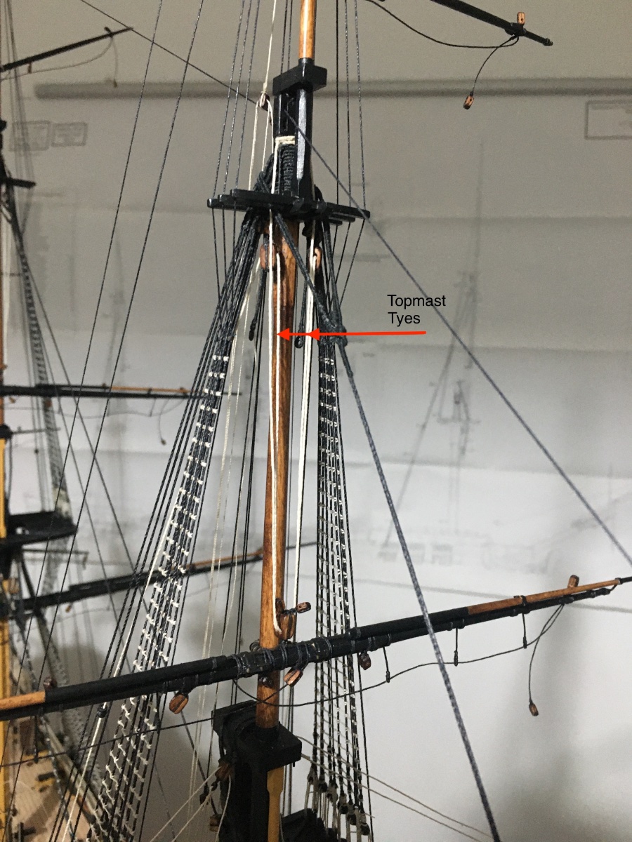
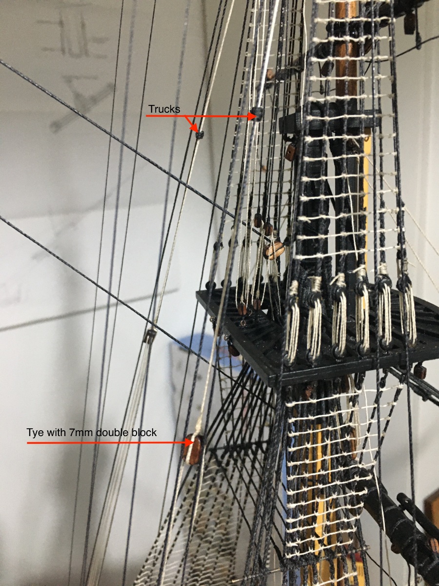
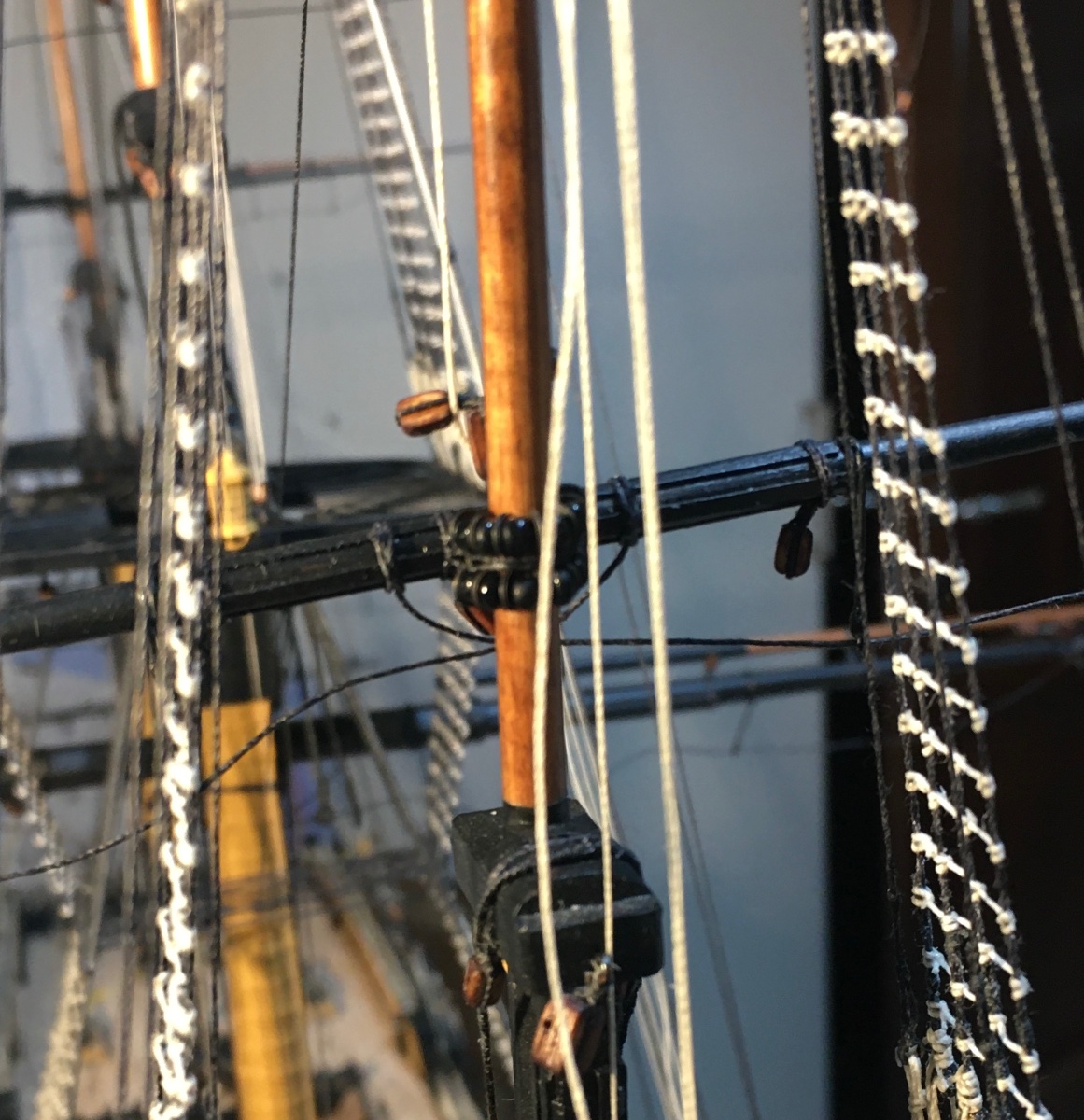
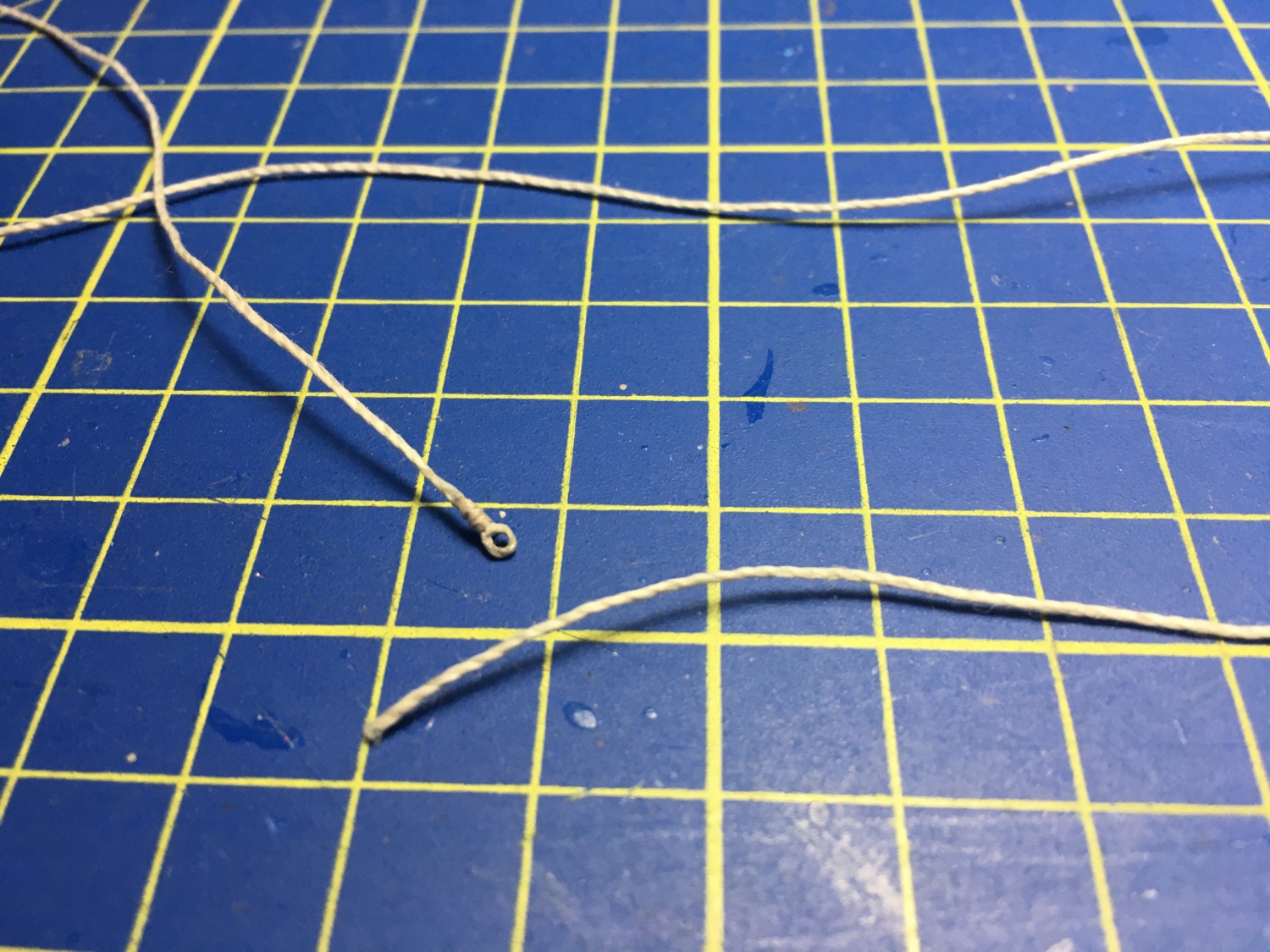
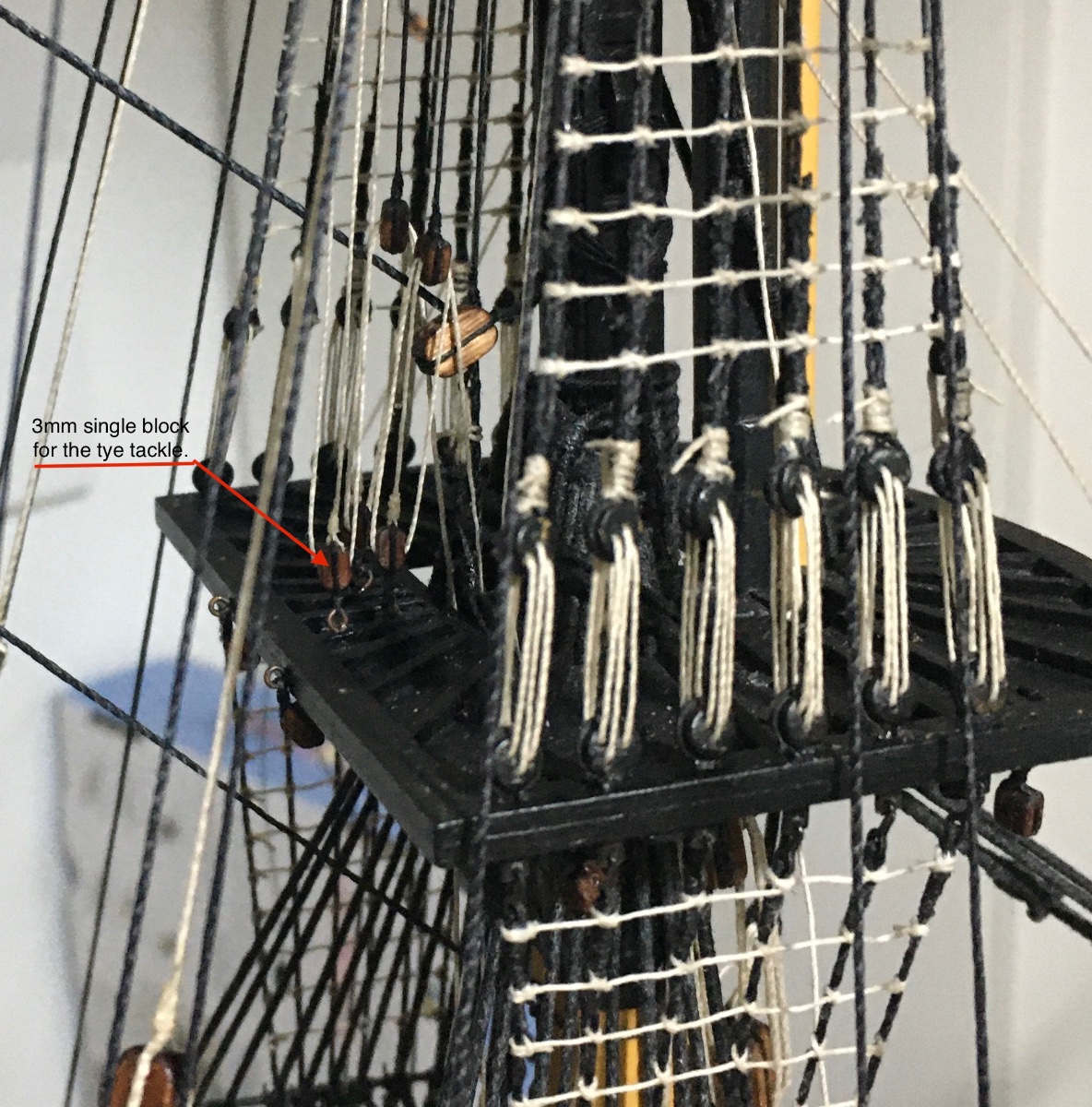
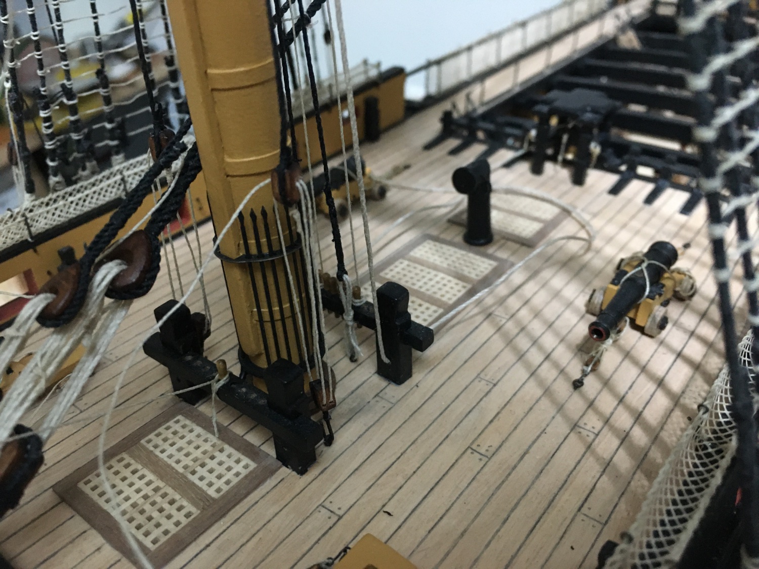
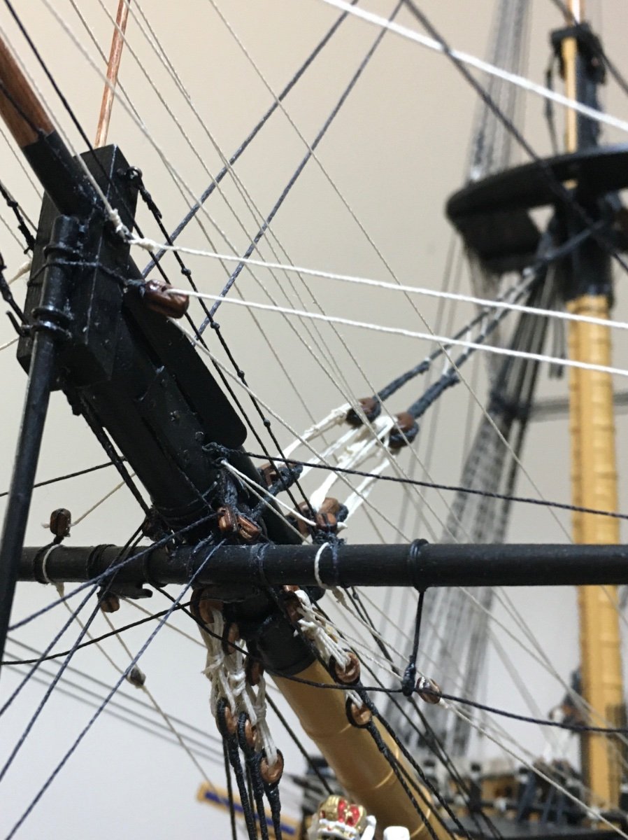
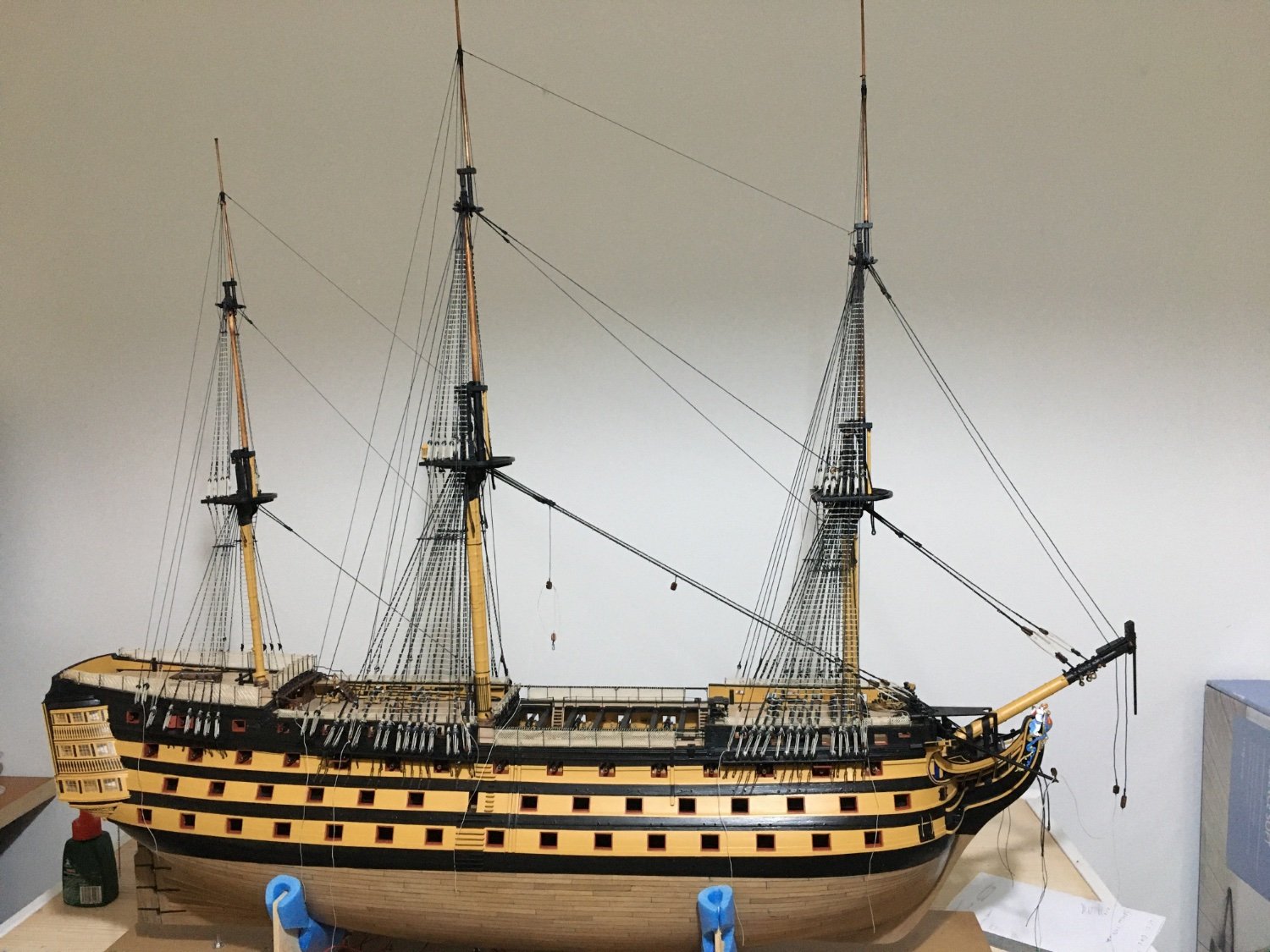
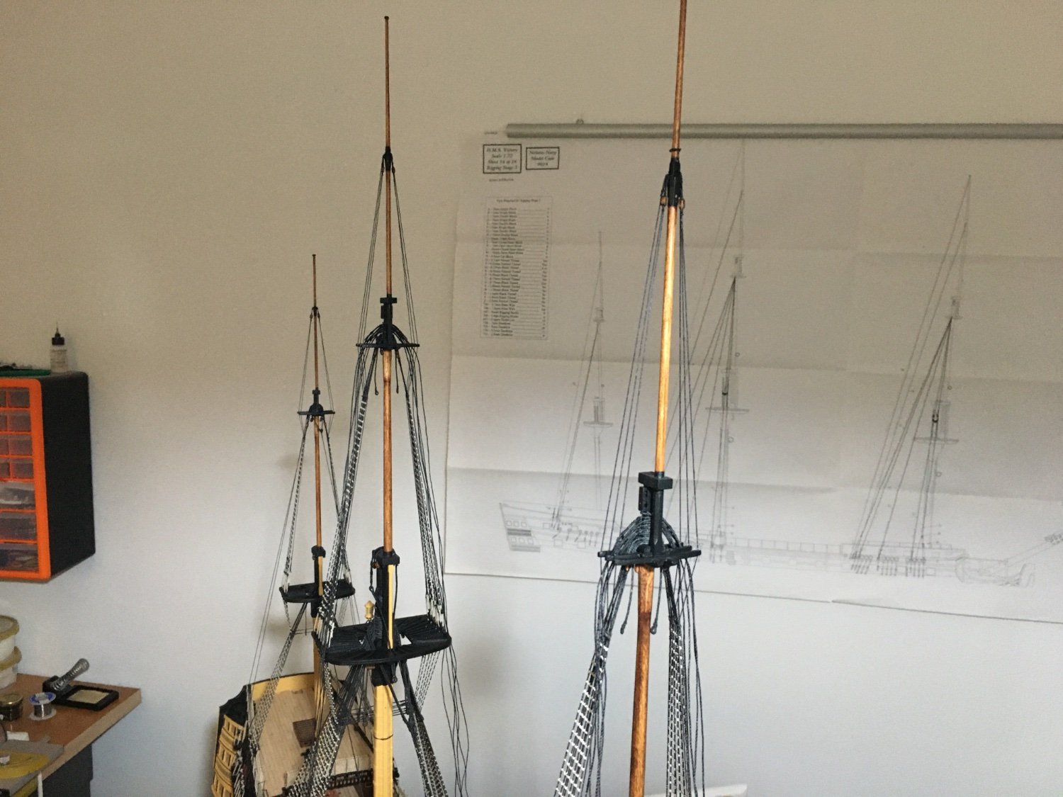
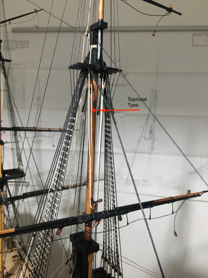
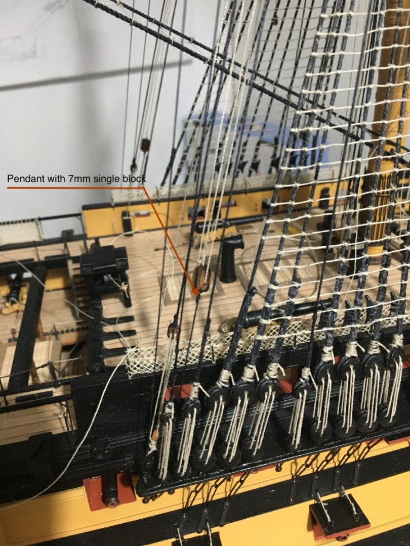
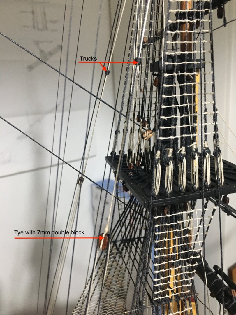
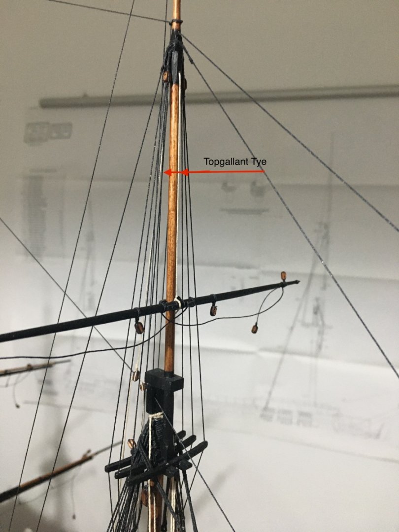
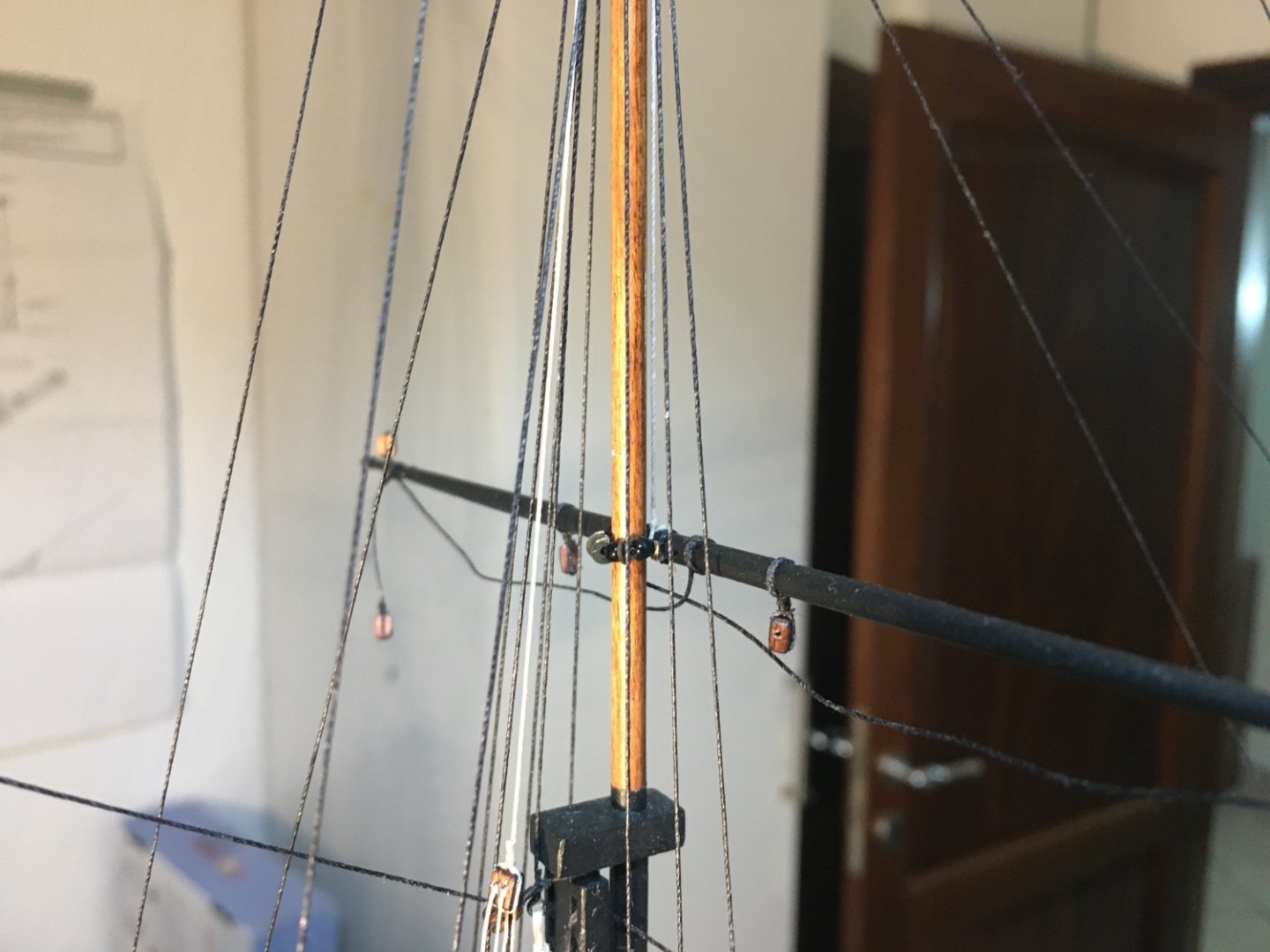
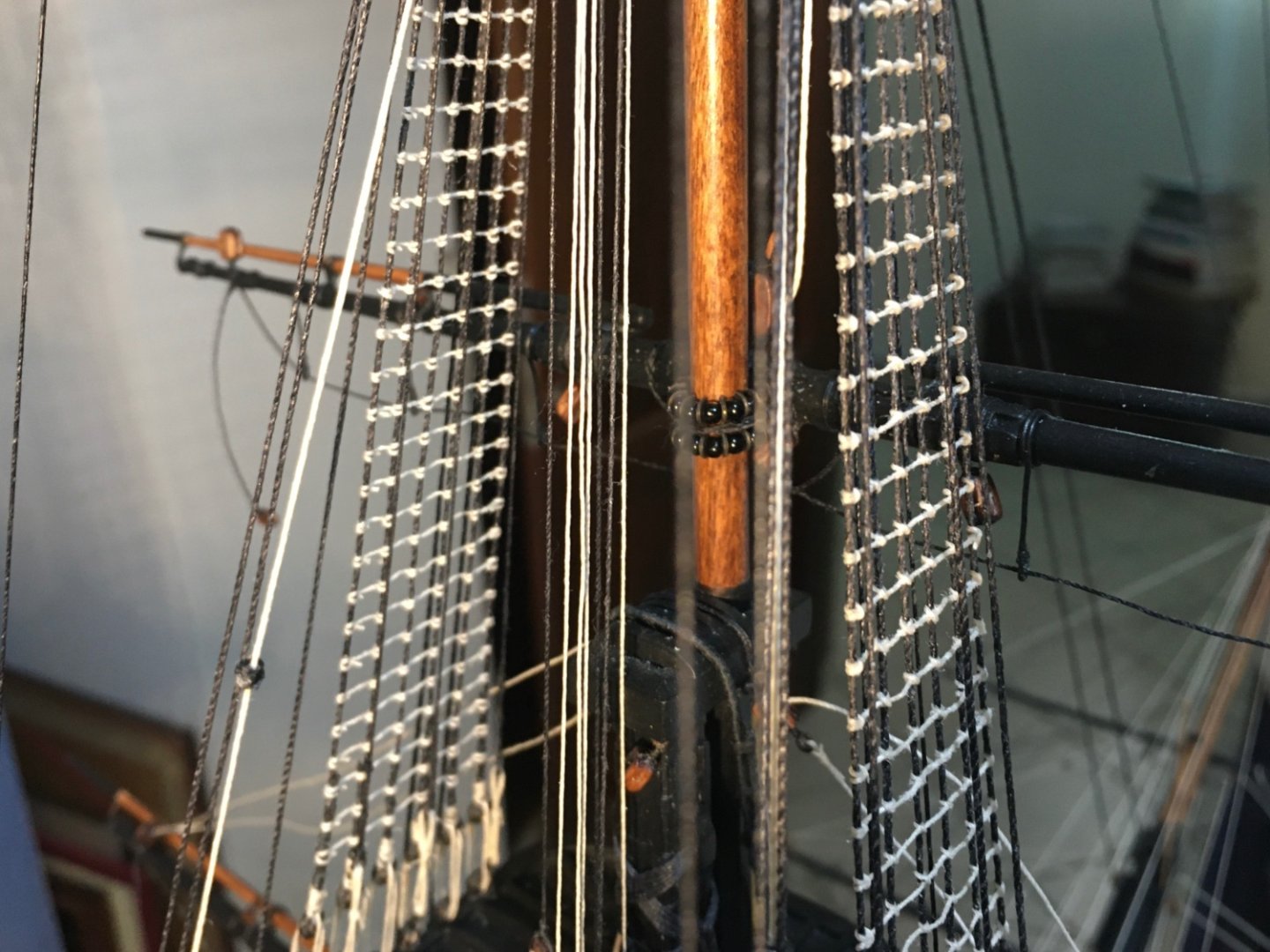
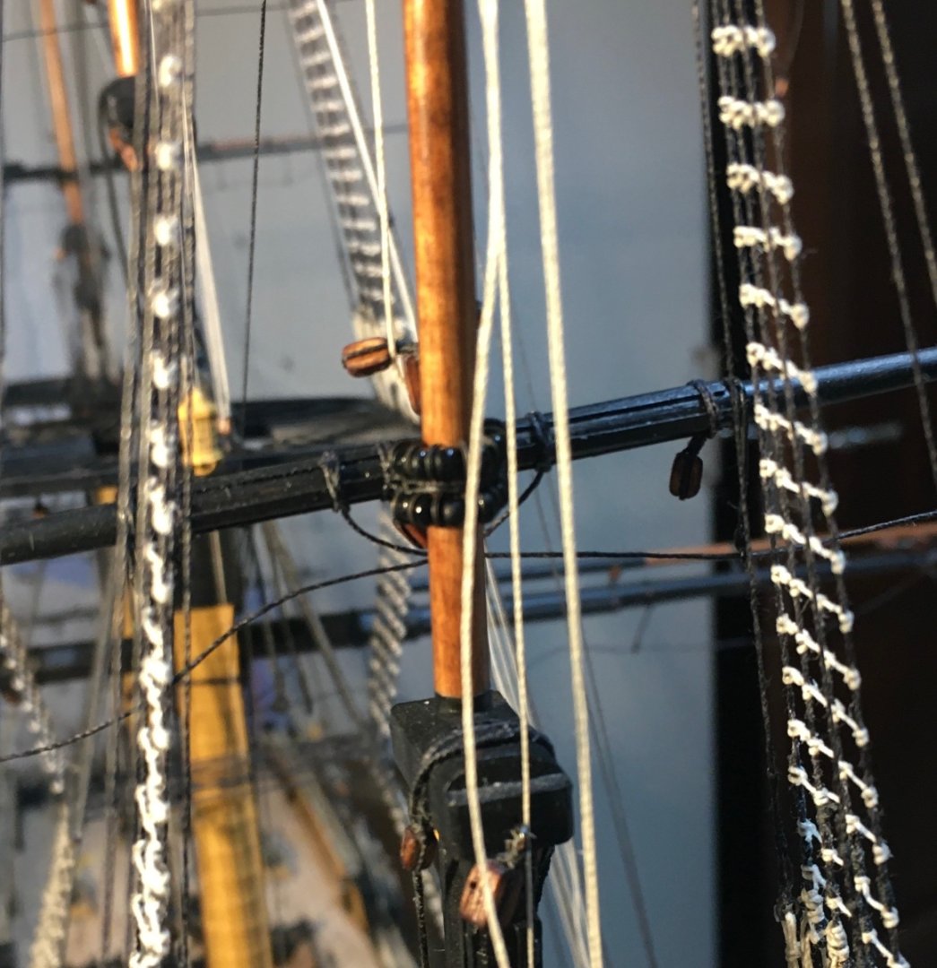
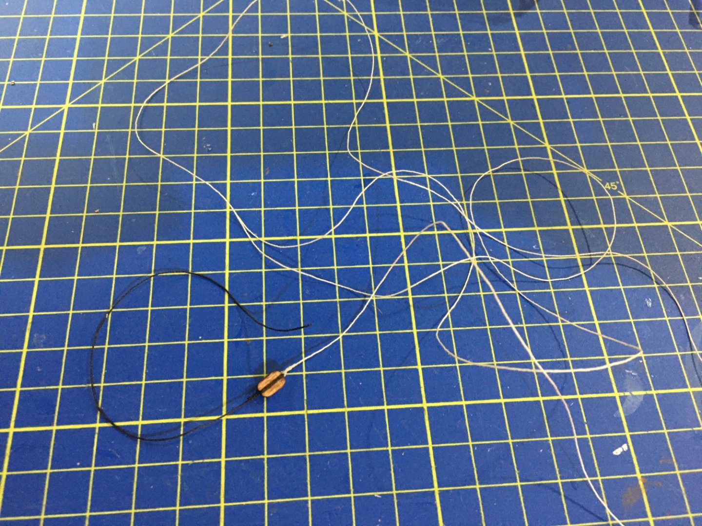
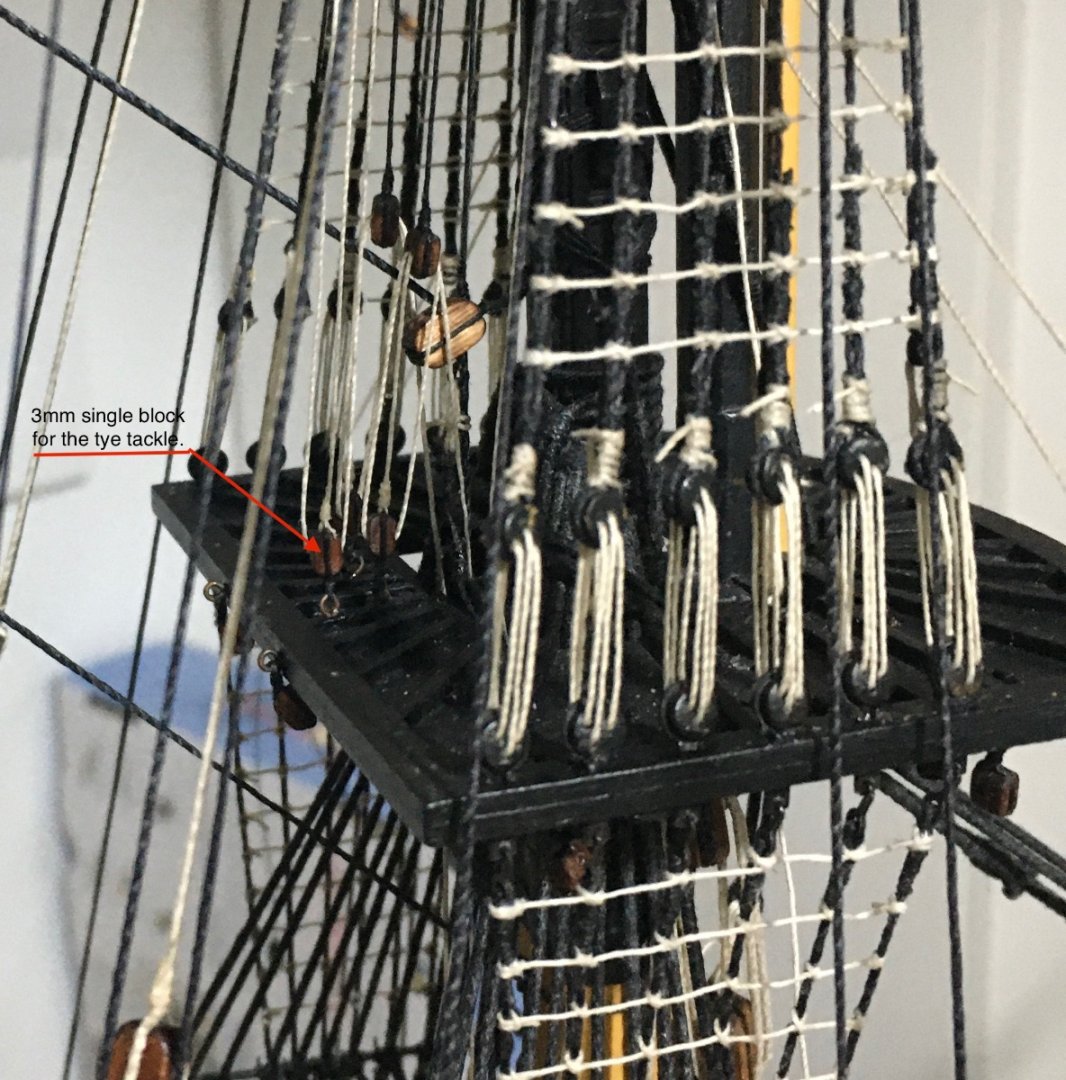
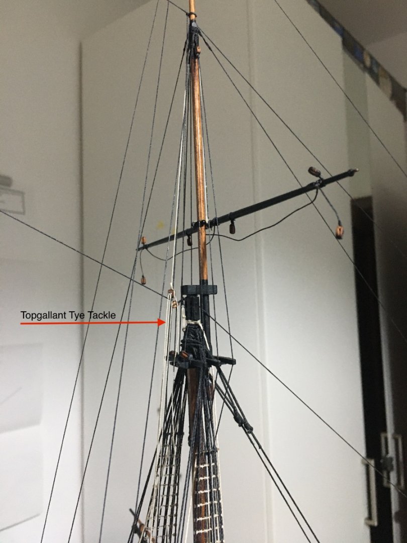
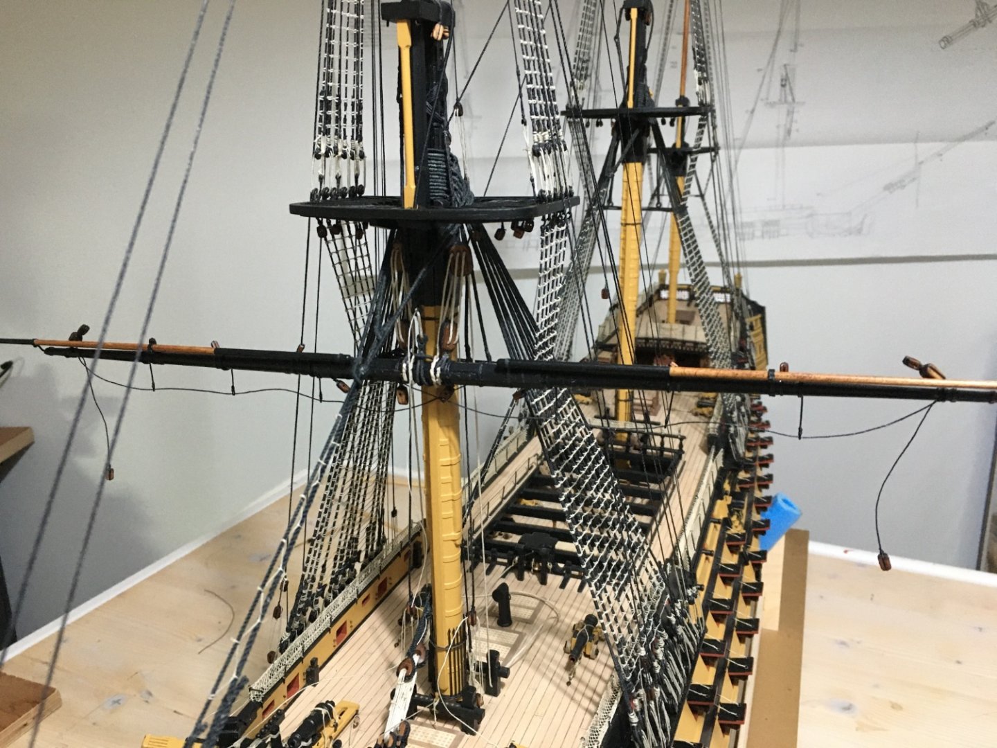
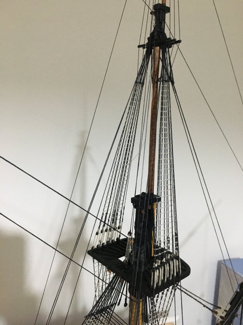
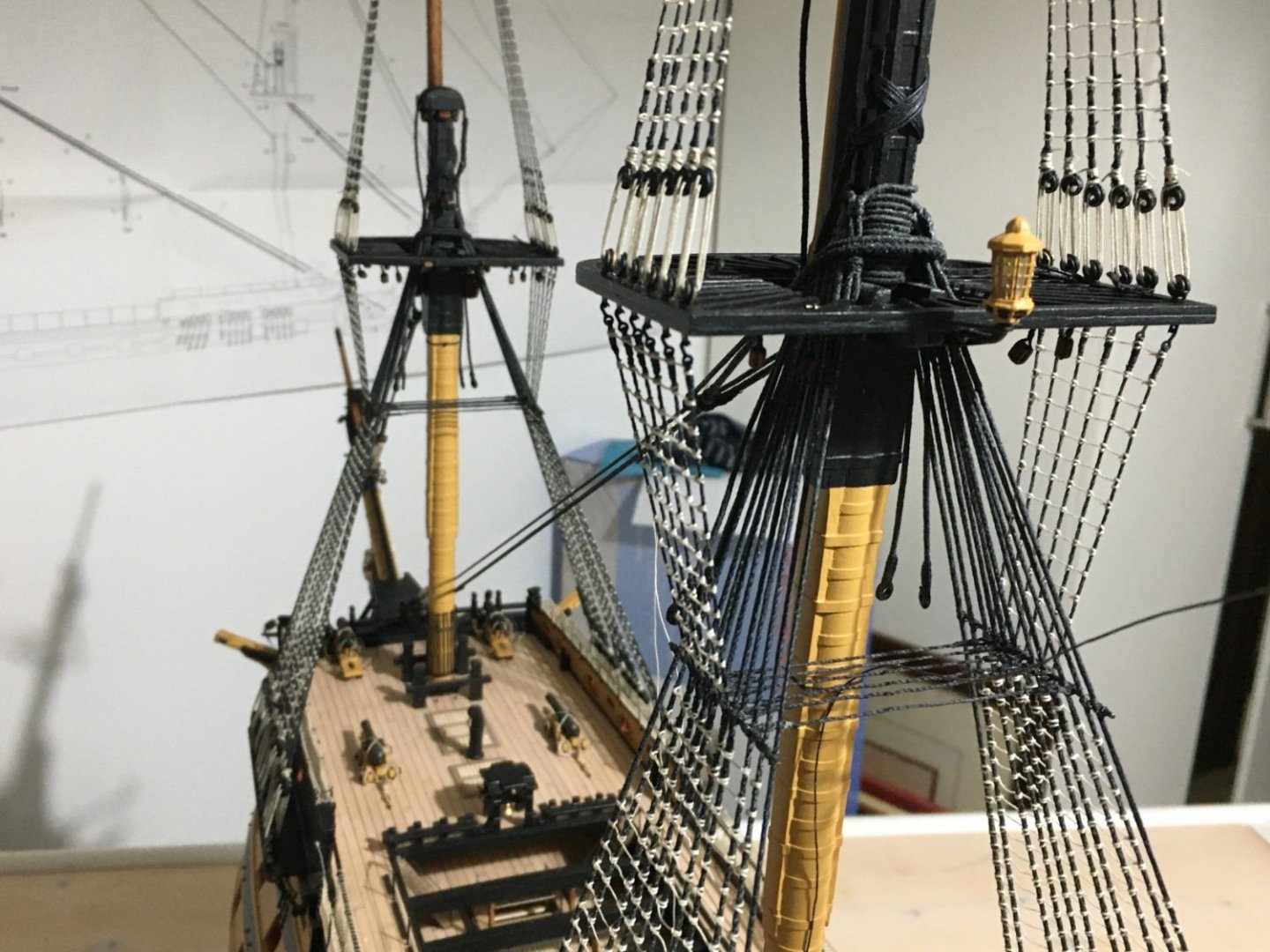
 More work on the yards. All yards for the three masts in place and their respective rigging in progress. Still a long way to go, but little by little getting there. Belaying the lines to the bitts is taking me ages. If anyone has a good idea how to do them is more than welcomed to share it. Basically now I have all the truss pendants, jeers, parrells and ties for all yards in place, except that some of them still need their ends to be belayed. I think I will not belay them for now until I rig the lifts, which will keep the yards more stable and in place. For now I am also not bothering about the exact sagging effect of the yard horses as while doing the rest of the rigging I keep hitting them and, so I will set them later on. Fore Topmast Parrells. Mizzen Topmast Parrells Fore Togallant Parrells Topmast Tyes prepared with an eye at one end so that it will be looped to the mast. Pendant prepared for the tye tackle. Tyes secured to mast, go down to the 7mm tye block, up again to a 7mm block, down again through a truck. Tye passes through truck attached t the topmast standing backstay and a 7mm double block seized at the end of it. Pendant seized in place to the eylet at the rear of the channel and a tackle is formed. Foremast Topgallant Tye tied to the middle of the yard, up and through a hole drilled in the hounds, down again and a 3mm double block is tied to the end of the tye. Block on Fore Top to form tackle. End of tackle goes down through the top to the deck. Belayed to the 7th pin. The rest of the Tyes are rigged more or less the same way, with obviously some difference such as belaying positions. I am missing one truck so the tye for the Mizzen Topgallant has to be put on hold until I receive a new one. My next step is to work on the lifts, buntlines and leeches but I think I will take a short break, working through all those lines I am starting to see double.🤩 Robert
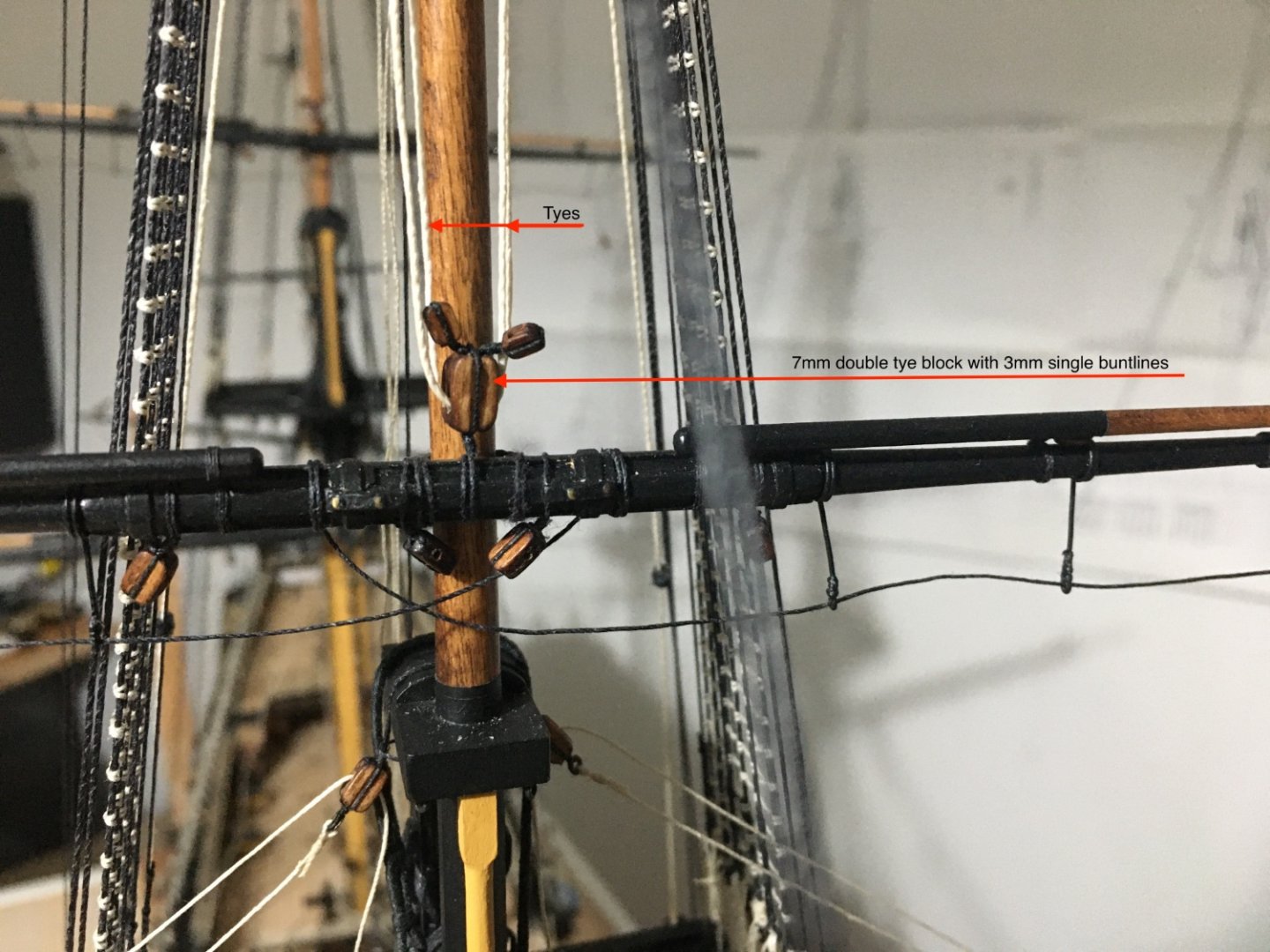

- 527 replies
-
- 11
-

-

-

-
- caldercraft
- victory
- (and 1 more)
-
Wow, great work on the stern fascia and the quarter galleries. Glad you took the extra work on the quarter galleries to create that bit of depth in the windows. It makes such a difference. When I was doing mine as per manual instructions I was so disappointed with the result and just couldn't leave it like that. Keep up the great work Graham. Robert
-
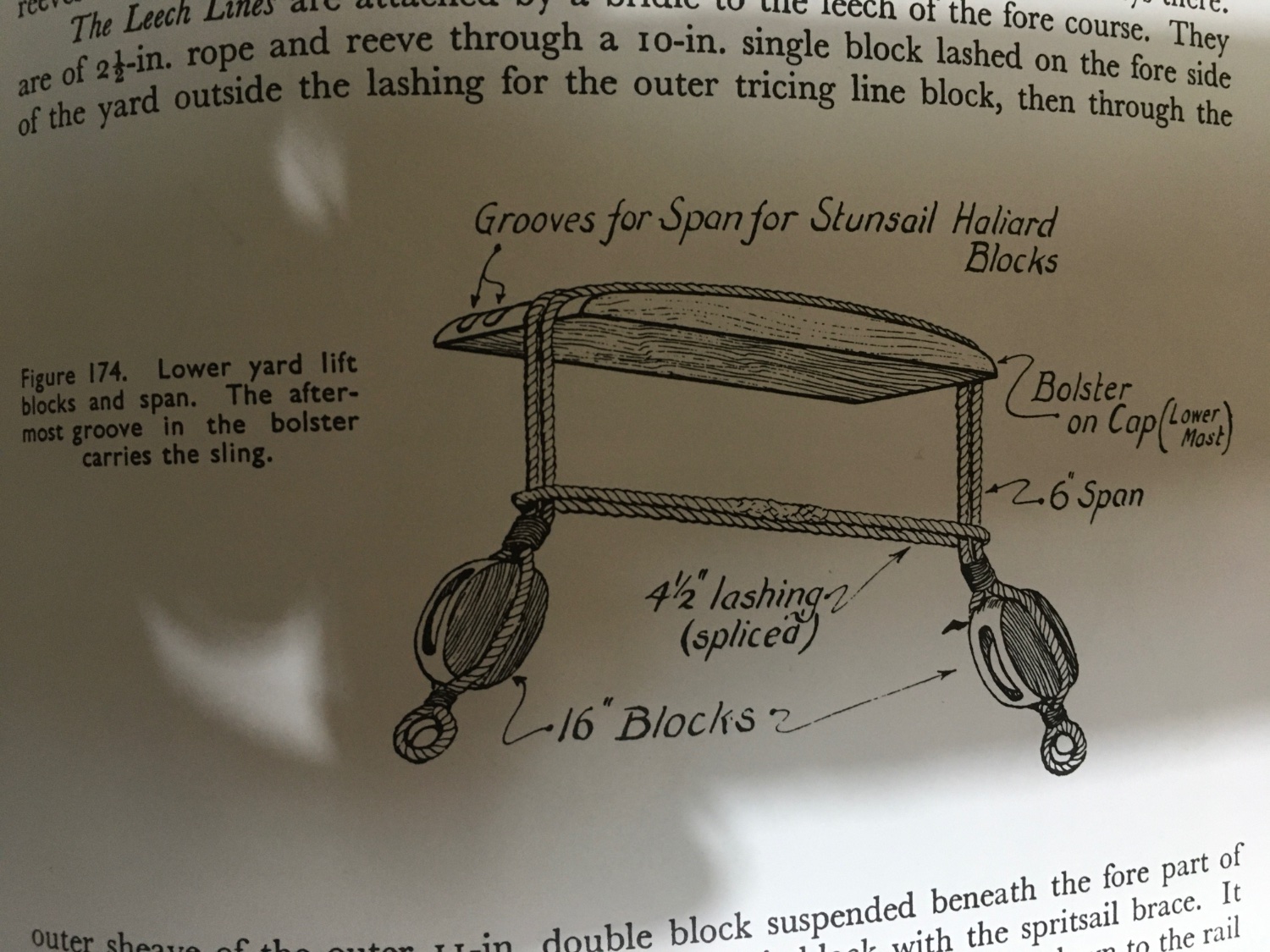
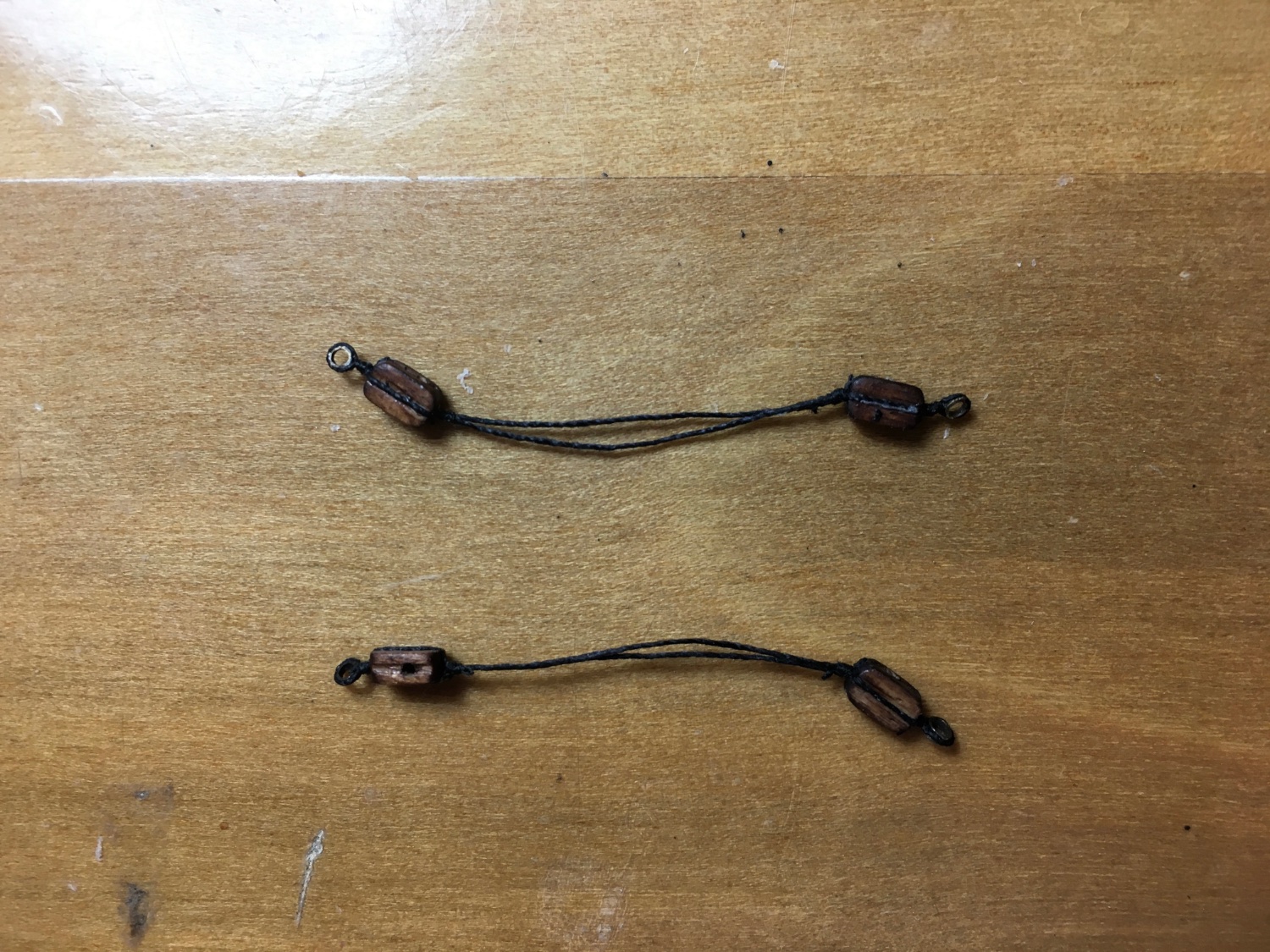
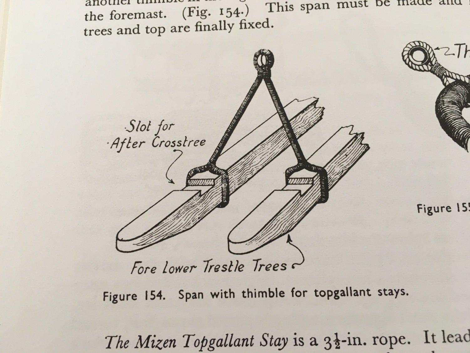
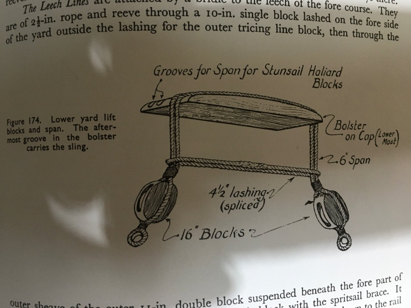
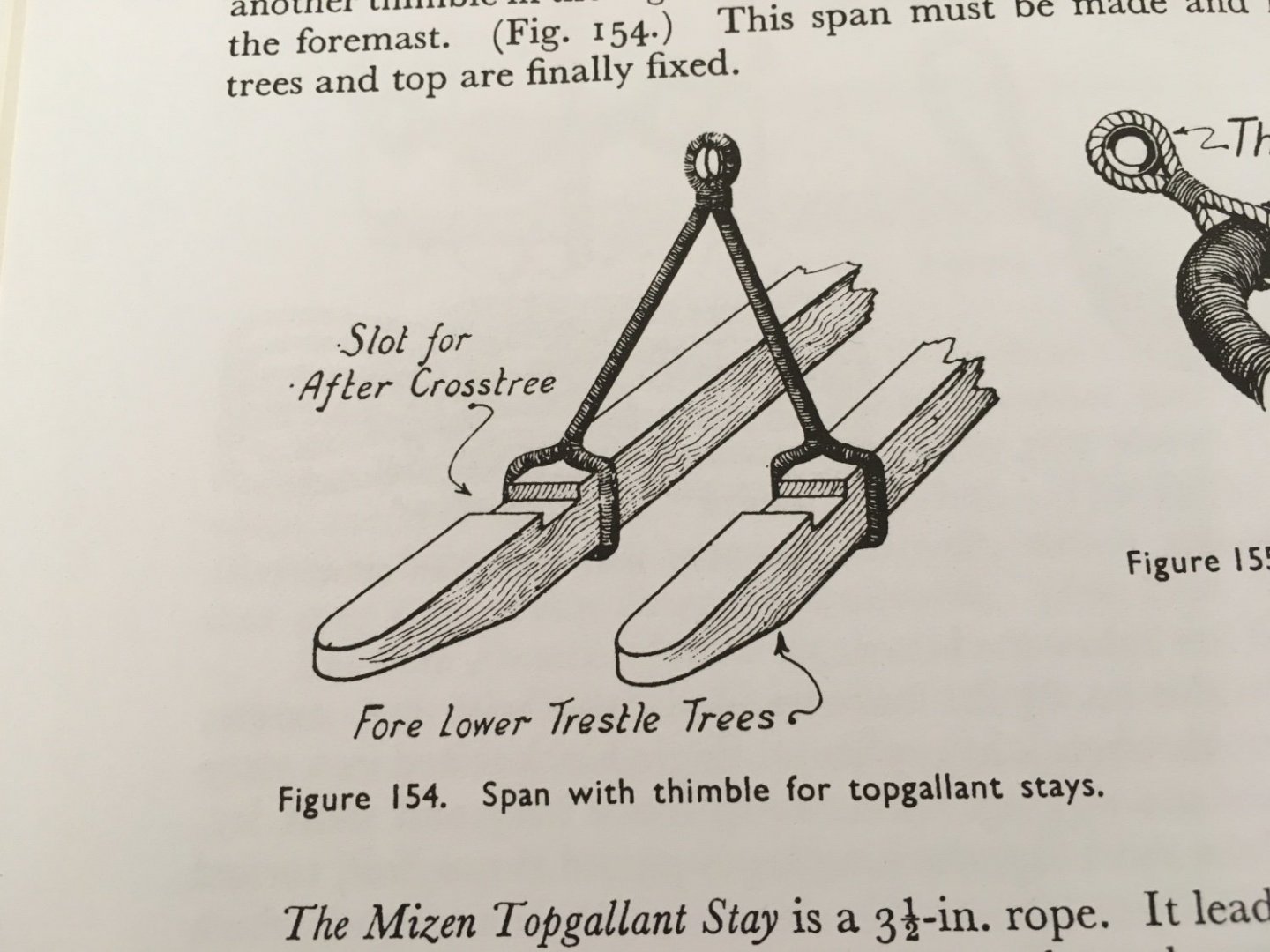
Graham and Martin, thank you for your comments and thank you all for the likes. My next step was to ship the Fore Topmast Yard. Whilst studying how to rig the parrels and seeing if I need to rig anything else before I fit the topmast yard I realised that the lifts for the lower yard have to be tied to the ars of the blocks tied round the bolster. I tried to tie the lifts to the ars of the blocks as later on it will be more difficult. But there was no way of doing it without damage. The thread round the block was tight and glued. So I removed them and replaced them with others I made as per Longridge drawing. The way I originally made them, no eyes or thimbles on the ars of the blocks. Drawing in Longridge Span with blocks and thimbles on the block's ars to take the lifts. Yard Lift Blocks in place. Now I can easily attach the lifts to the thimbles, even at a later stage. Robert


- 527 replies
-
- 8
-
-
-
- caldercraft
- victory
- (and 1 more)
-
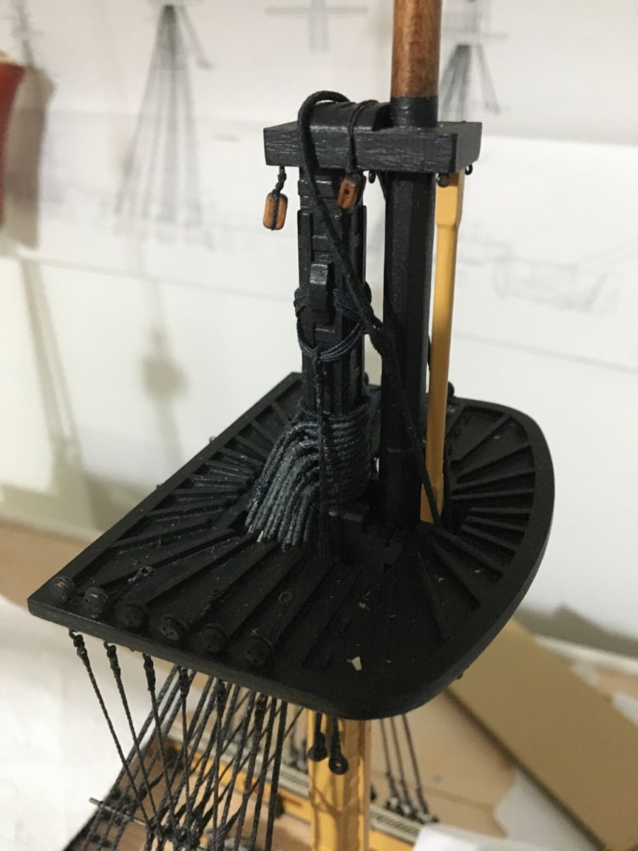
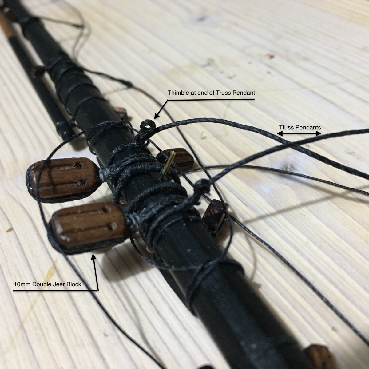
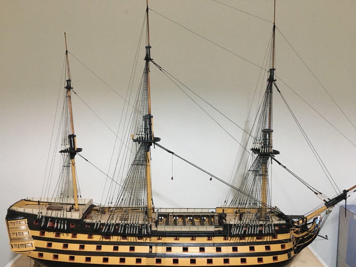
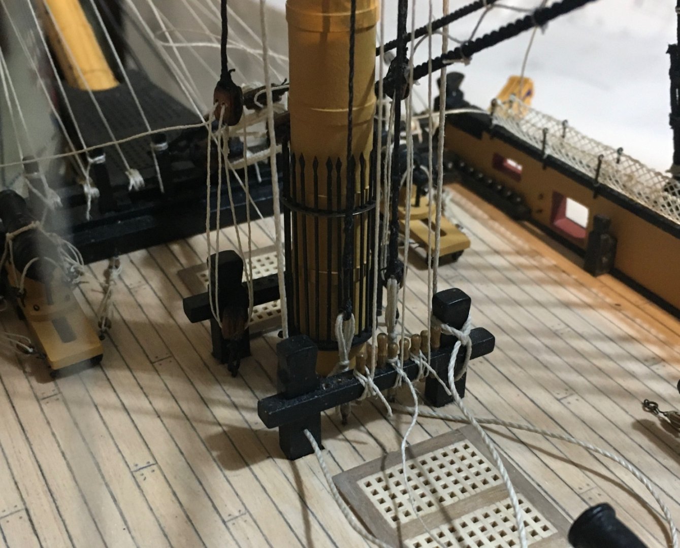
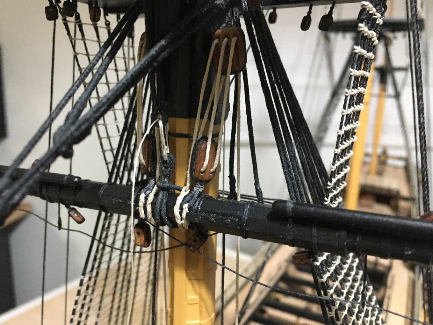
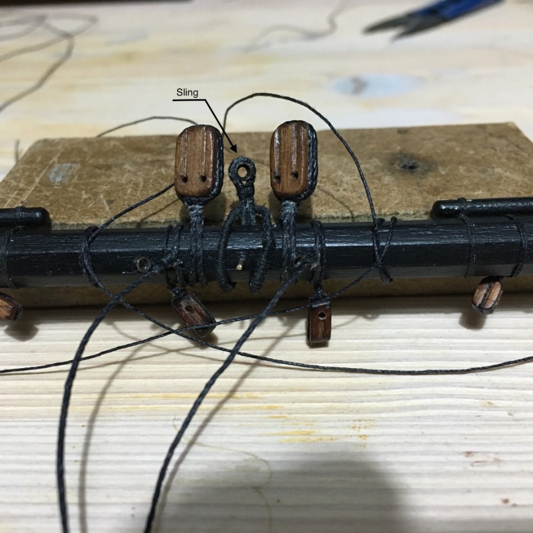
Thank you Ron. Good luck and enjoy your Victory Build. I will be looking into your build. A long overdue update. It has been 2 months since my last update. Had other priorities and my build was on 'go slow'. Also had to go for my grandson's first birthday in UK, Stratford-Upon-Avon, and spend some days there, where my daughter lives. I started fitting the first yard on the fore mast. I tried to rig as as much as possible on the Fore Yard as it is much easier done when it is in hand than when it is in place. In the manual the sling is made in one whole piece which goes round the yard and up around the mast cap with two knots simulating the thimbles. In actual fact it is made up of two slings, one which goes round the mast cap with a thimble on the lower part, which I had already prepared some time ago, and another sling round the yard with another thimble. With the yard and sling in place the two thimbles are lashed together. The loose thread showing in the picture is the inner end of the horses, for the moment left loose so I can tension them later on with a sagging effect. Truss pendants rigged in place with a thimble at the end. Yard in place. Jeer falls and sling lashing still need tensioning and finishing. The Jeer falls were also secured round the yard before fitting yard in place. Blocks at end of Truss Pendants had to be rigged after the yard is in place otherwise you wan't be able to pass the thread through the thimbles at the yard. Robert


- 527 replies
-
- 10
-
-
-
- caldercraft
- victory
- (and 1 more)
-
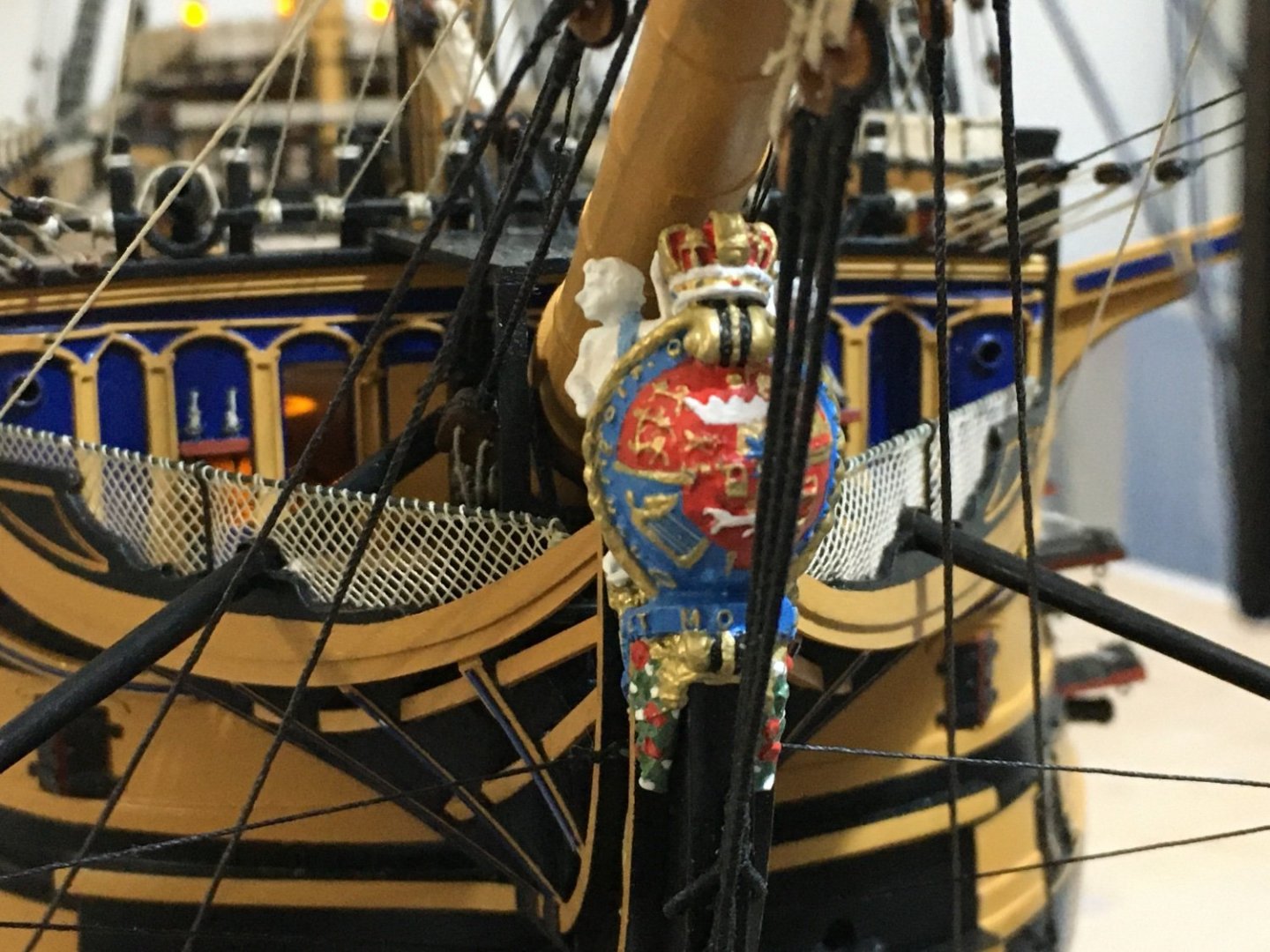
Thank you RockinBudgie. Mort, sorry, forgot to reply to you about the hearts on the bowsprit. I made them from 3mm dead eyes. To be honest I ran out of 3mm dead eyes and made a couple of them from 5mm deadeyes. I just drilled a hole in the centre bringing the three holes into one bigger hole and some sanding. Robert
- 527 replies
-
- 1
-
-
- caldercraft
- victory
- (and 1 more)
-
Beautiful decking Graham and great job with the treenails. Robert
-
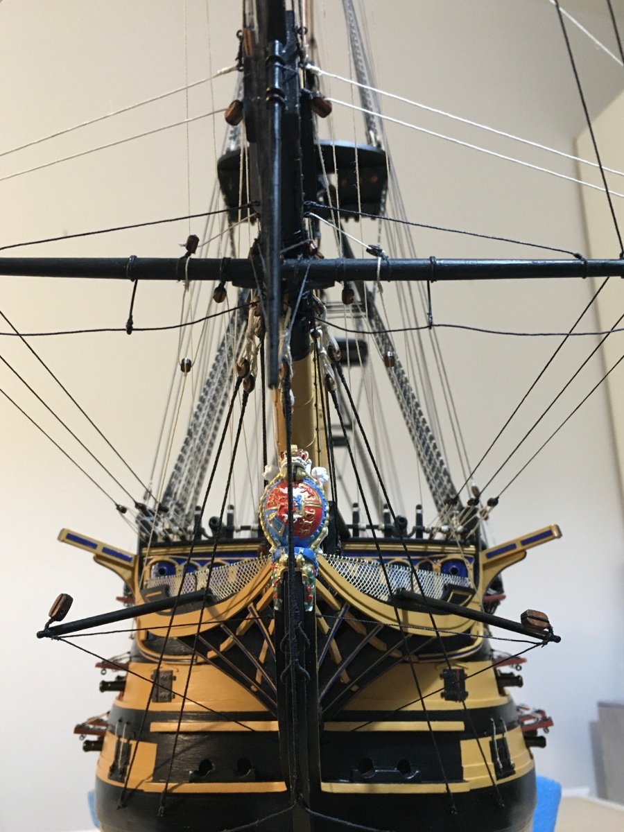
Thank you Graham and thank you all for the likes. With all the gunports shipped and all Stays and Backstays in place I thought its best to concentrate on the bowsprit rigging and finish as much as possible before moving to the Fore, Main and Mizzen yards. It involved more work than I had thought. Because I added the travellers, Jib Outhauls and Inhauls I had to divert quite a bit from the kit rigging instructions. I basically followed the rigging as per Longridge book. With nautical terms being all new to me it was no easy task to follow and make the changes from the kit's manual to Longridge. There were some differences of bowsprit rigging/belaying from kit's manual to Longridge. I did them to my best understanding and ability and I apologise for any rigging which might not be truly as per the Victory's prime. Here are a few images. I still have to make the rope coils and fit them at the belaying points. Robert


- 527 replies
-
- 14
-
-
-
- caldercraft
- victory
- (and 1 more)
-
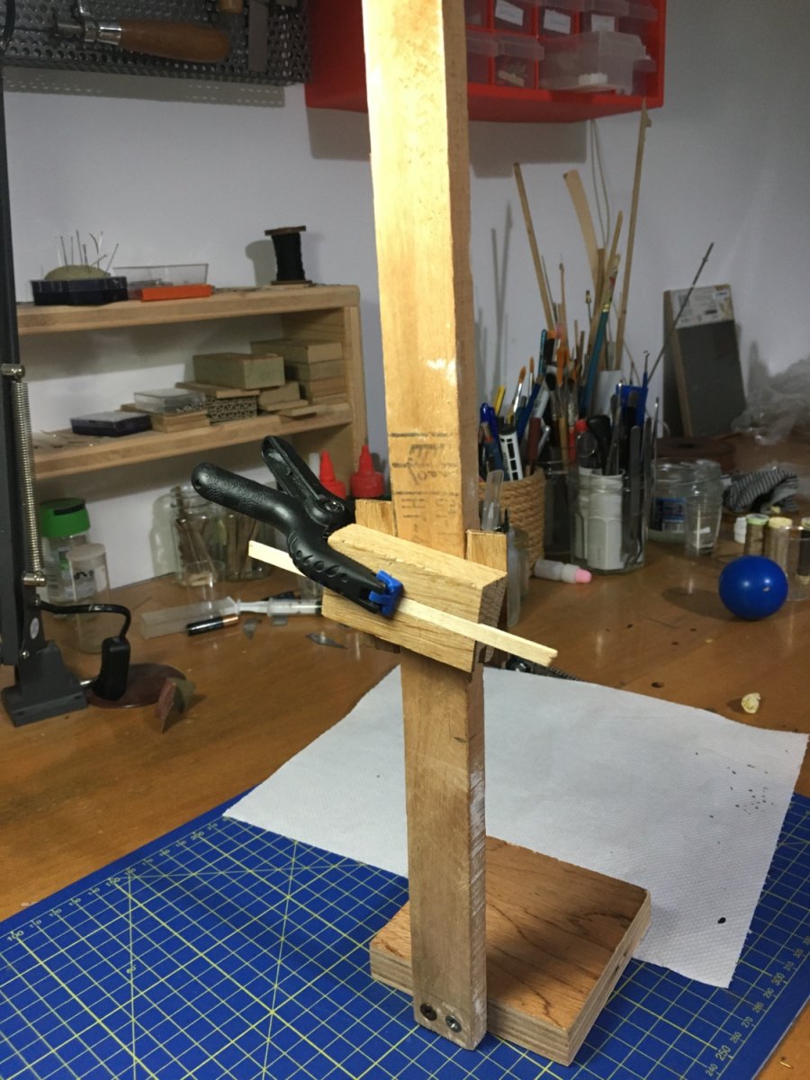
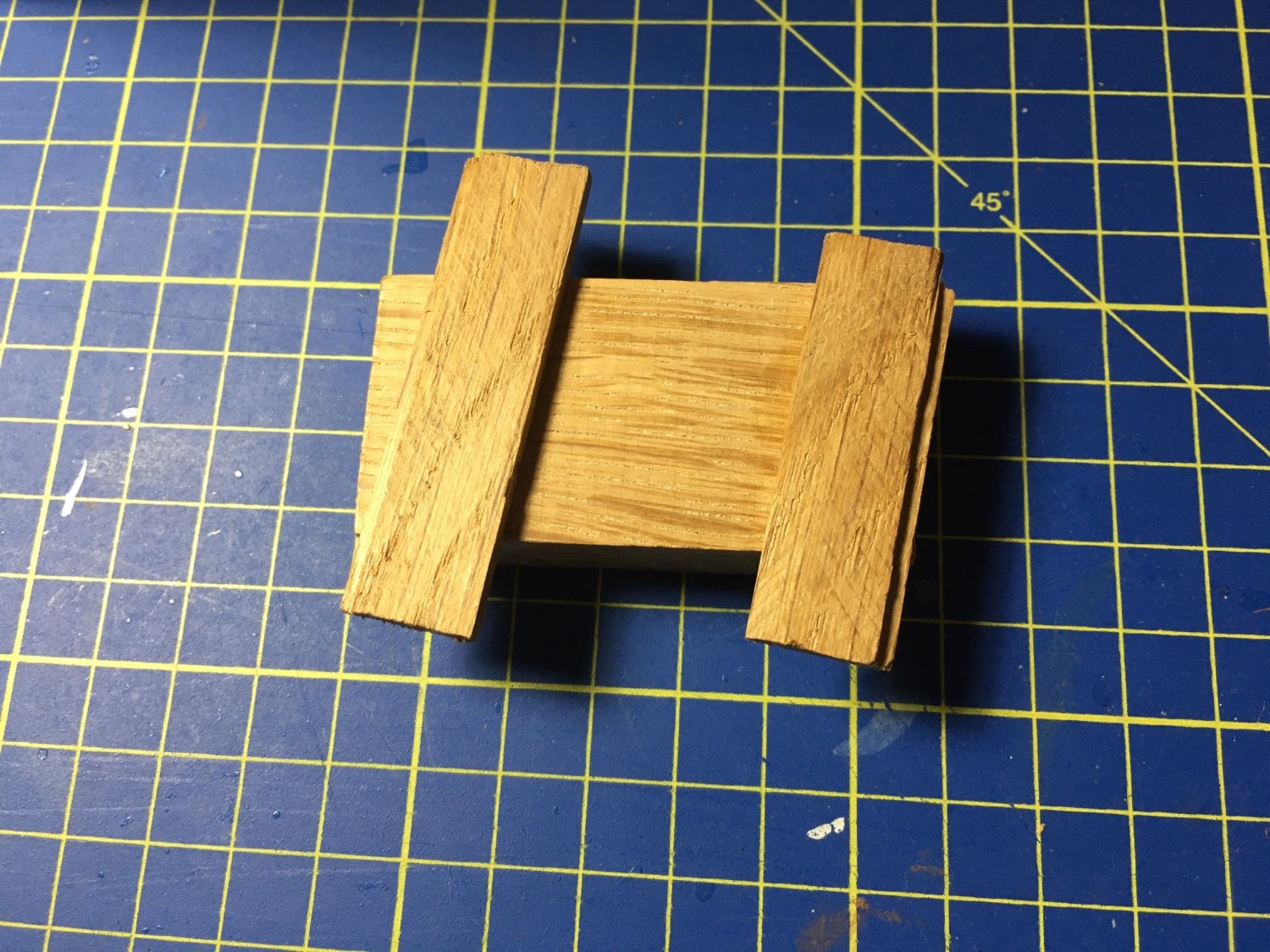
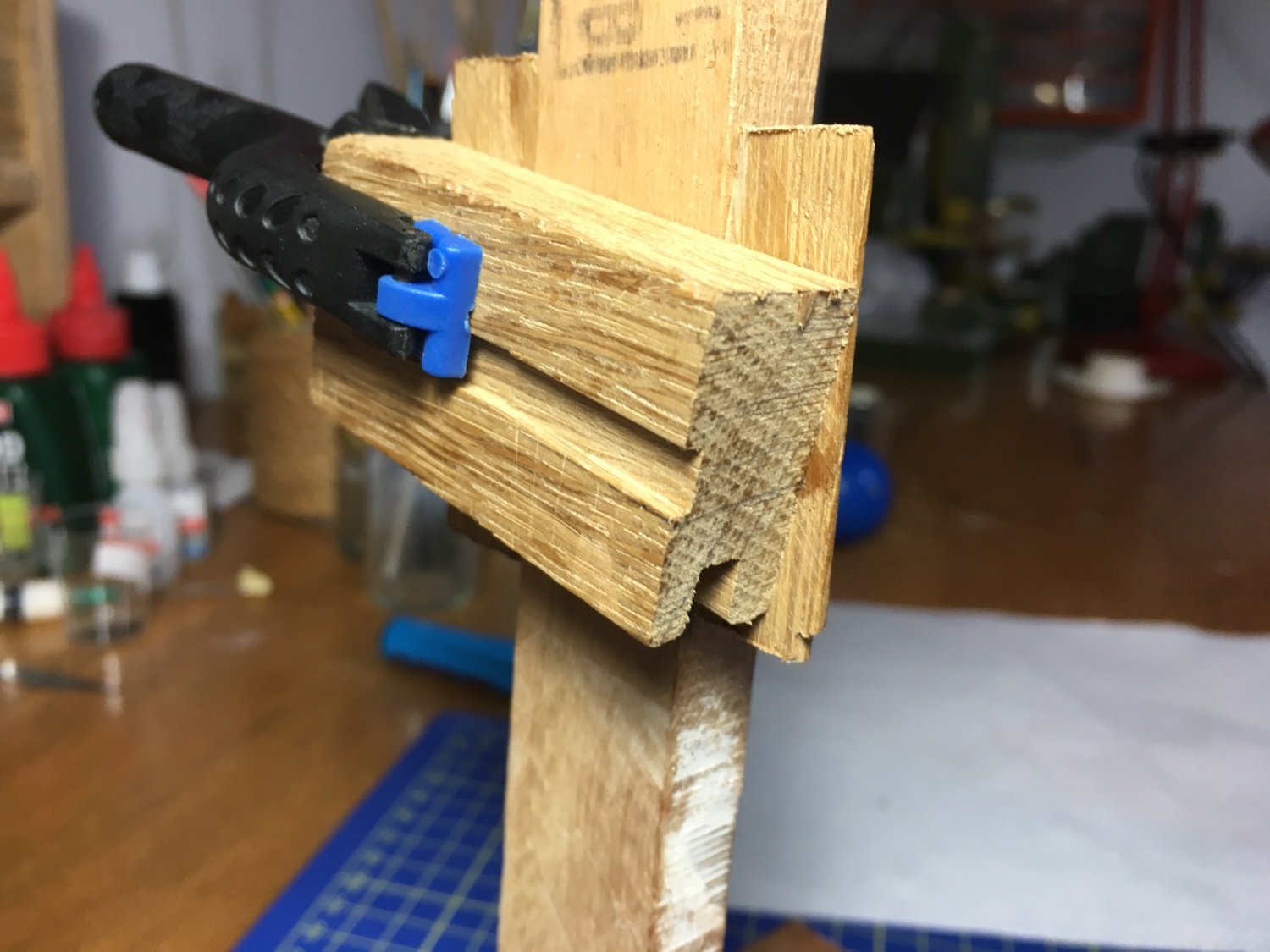
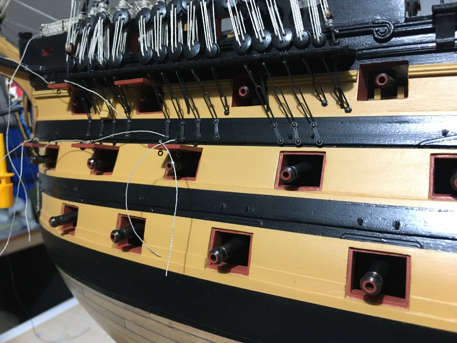
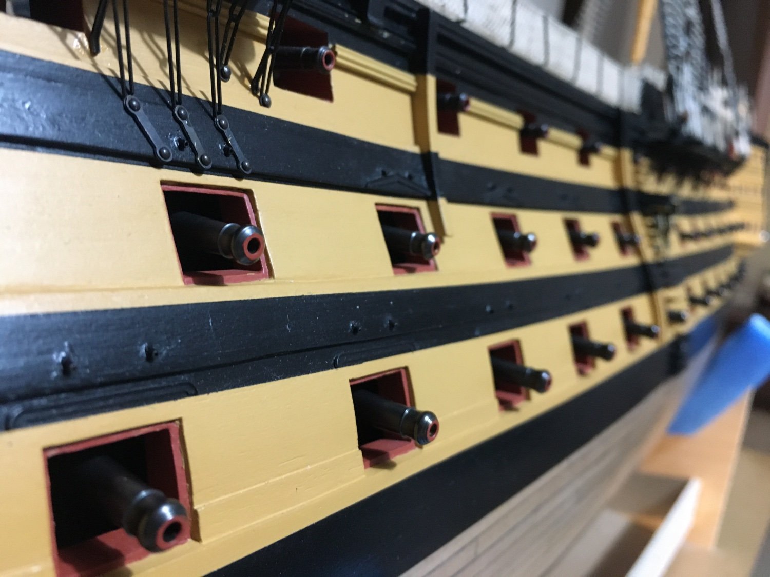
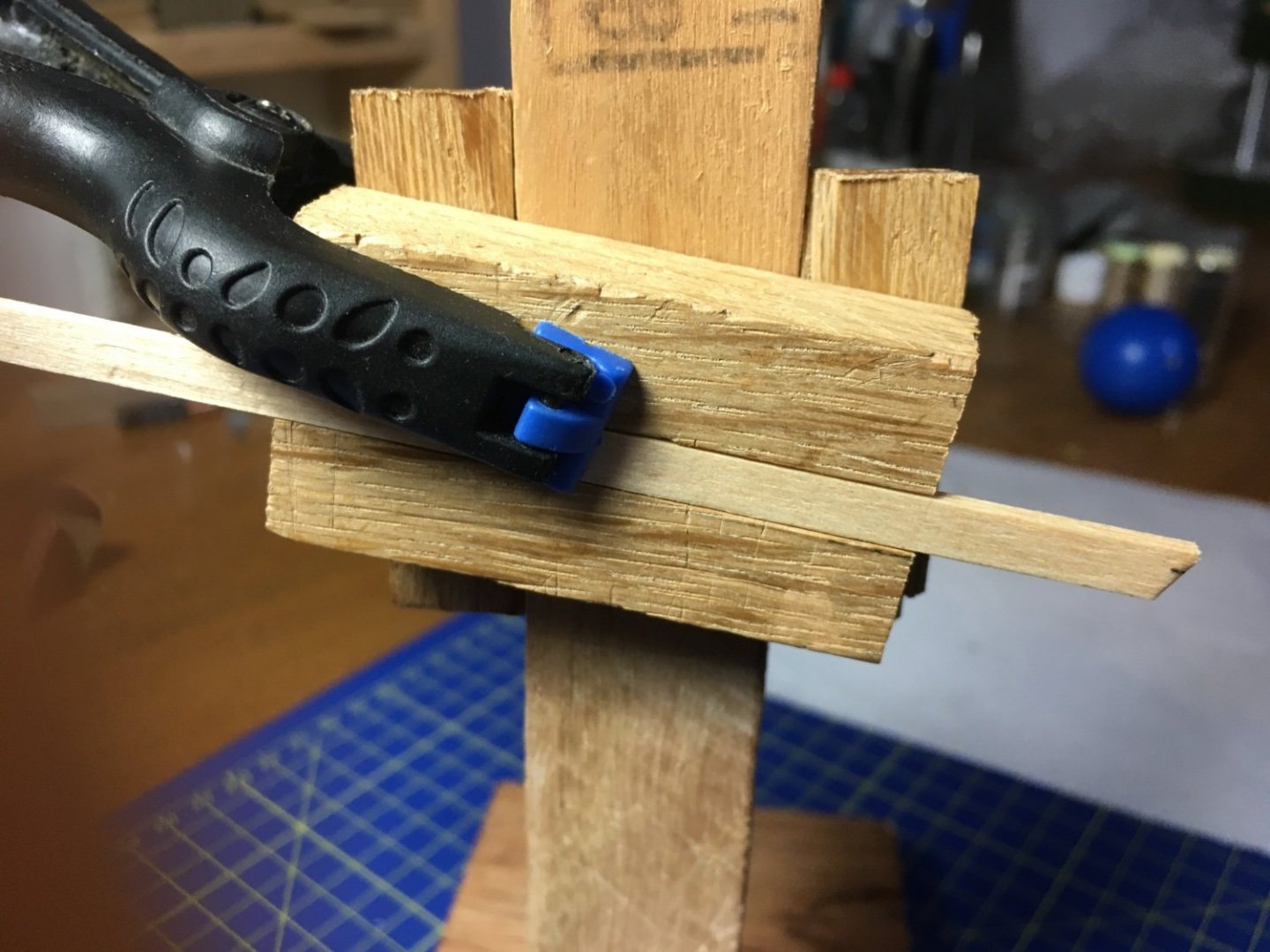
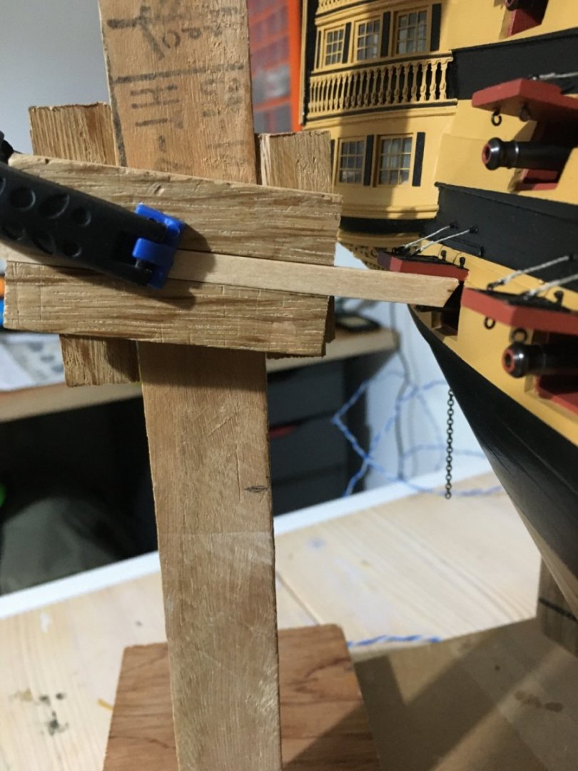
lan and Oldsalt, thank you for your feedback. Yes you can only do so much to replicate what was during their prime. I think it depends on three factors. a) How much you are ready to source, b)how much details you manage to source and c)the ability to replicate them on the model, depending on your skill, sometimes very difficult or impossible because of the small scale. In my opinion sometimes it is better to leave some details out than try to replicate them with a poor result. I finished all the gunport lids. I had made the lids some time ago and put them away to finish some rigging before fitting them in place as I am sure I would have nocked down a few of them. Probably I will still manage to nock down a couple of them, but at least the risk is minimised. I made a jig to keep the opening angle of the lids the same as much as possible. Here are a few images, quite crude but very useful. It was made from scrap I had laying about. I found a piece of wood, I think it was cut fro some sort of wall panelling. It had a groove on one of the faces. I glued two pieces of wood to it to act as guides to go up and down the upright stand and always keep the block at the same angle. Put a strip of wood in the groove. So basically now I have the block of wood that can move up and down, depending on the height of the gunport, and the strip which can slide in and out to the required distance. Jig in use. Here are a few images of the finished job. Robert


- 527 replies
-
- 11
-
-
-
- caldercraft
- victory
- (and 1 more)
-
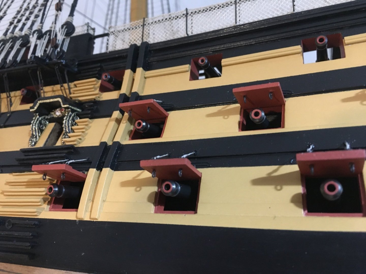
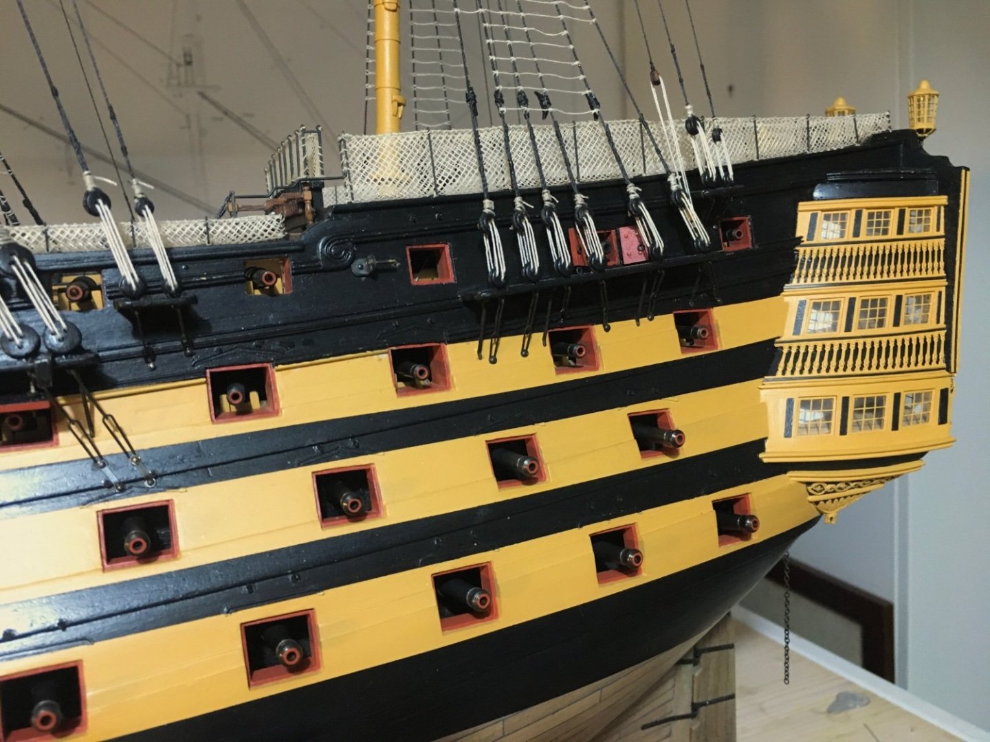
Graham and Allan thanks for your comments. Allan also thank you for your gunport comment. When I was doing the gun ports I just went along as per the kit manual instructions, which indicated four port stops. Then I saw some photos of the HMS Victory at Portsmouth and the gunports in these images do not have a stop at the bottom sill. But by this time I had already done all the linings of the gunports and it was too late to change them without doing other damage, so decided to leave them as is. So you are right, I do have an extra stop in the gunports, but I was always under the impression that the extra stop I have is at the bottom sill. Actual image of gunport on HMS Victory at Portsmouth. I have started fitting the lids and as you can see the hinges and the way the lids are fitted aren't exactly a replica of the real one. In fact the way they are fitted in the kit the lid covers the top stop. Allan just for curiosity's sake, do you think that, maybe, the gunports at the HMS Victory at Portsmouth were altered during a restoration? Robert

- 527 replies
-
- 2
-
-
- caldercraft
- victory
- (and 1 more)
-
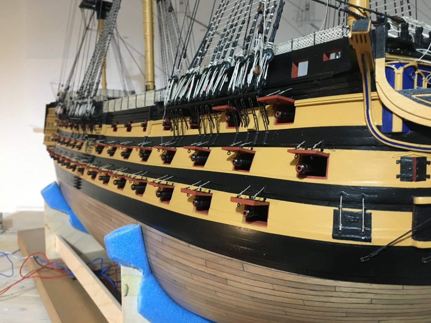
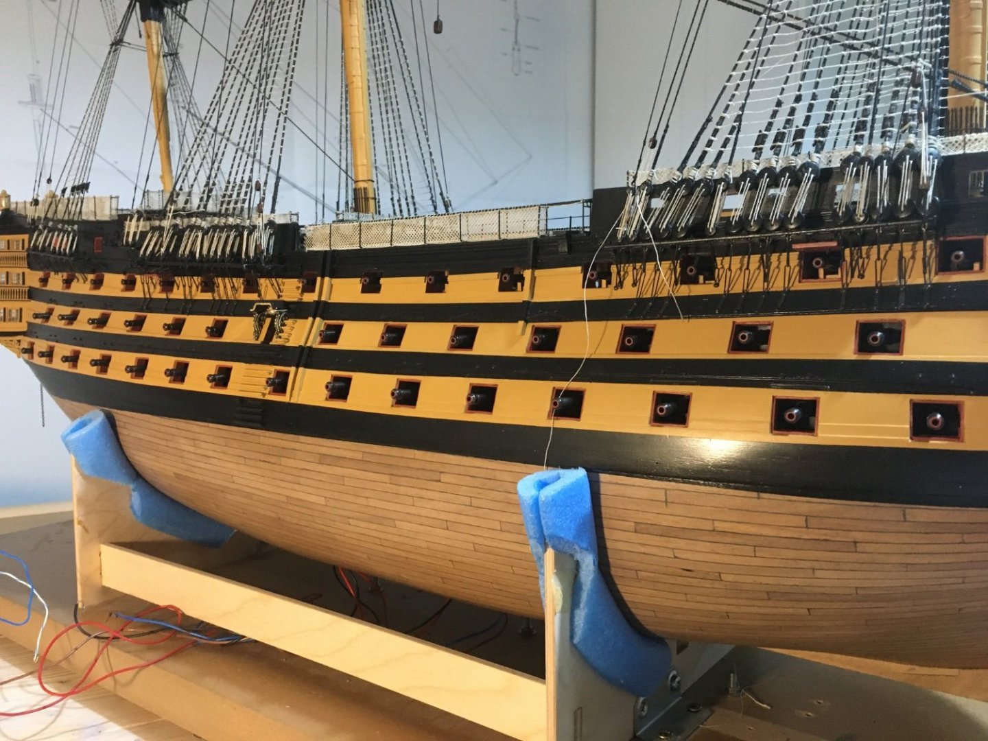
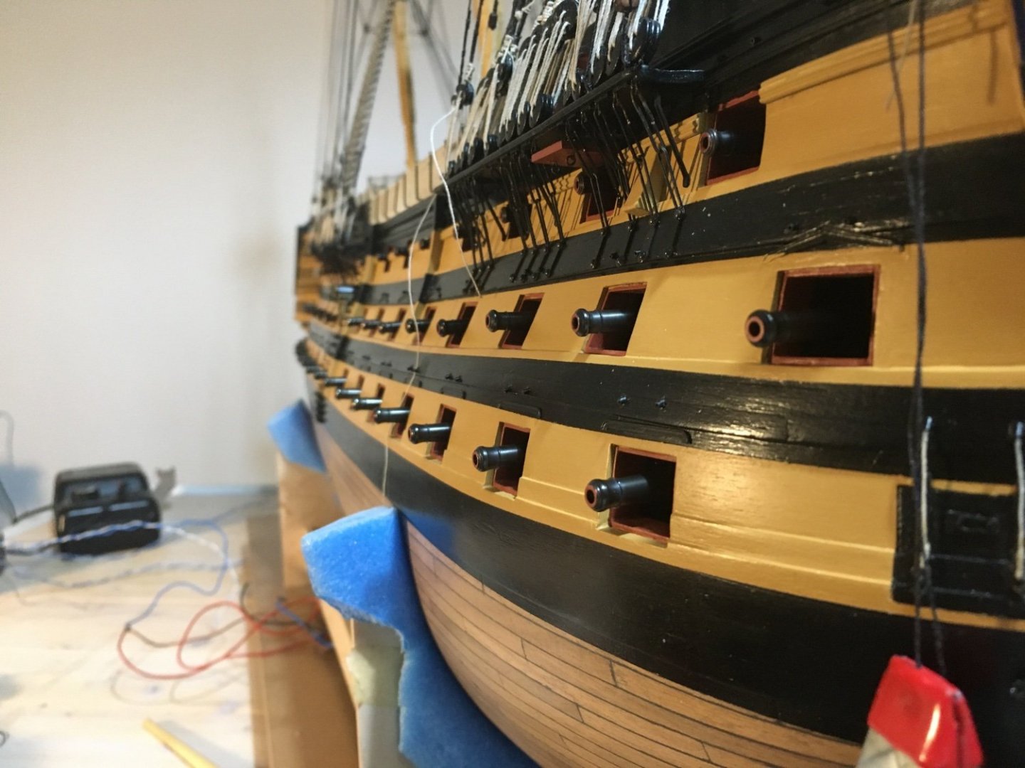
All cannons in place. Now to start installing the gunport lids. Robert

- 527 replies
-
- 9
-
-
-
- caldercraft
- victory
- (and 1 more)
-
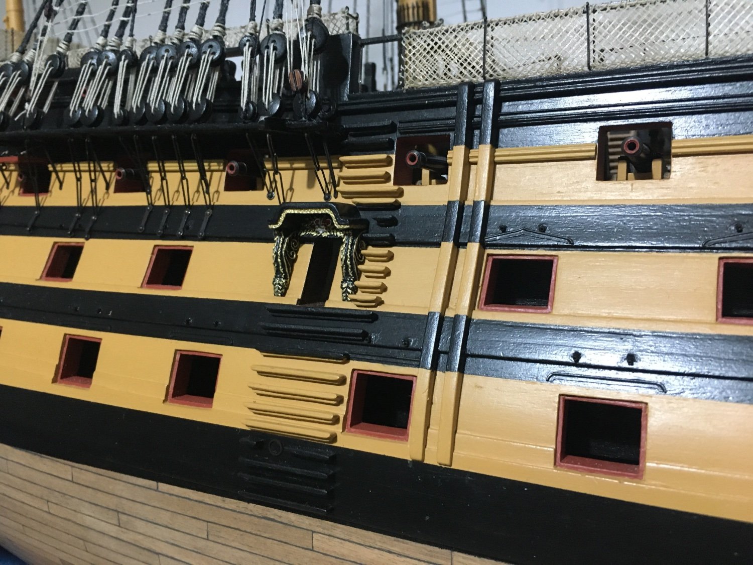
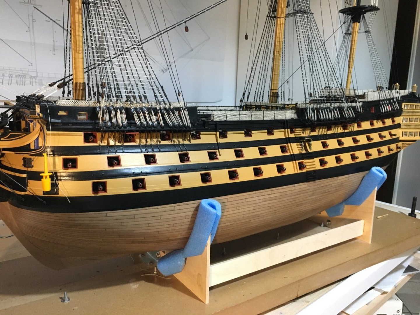
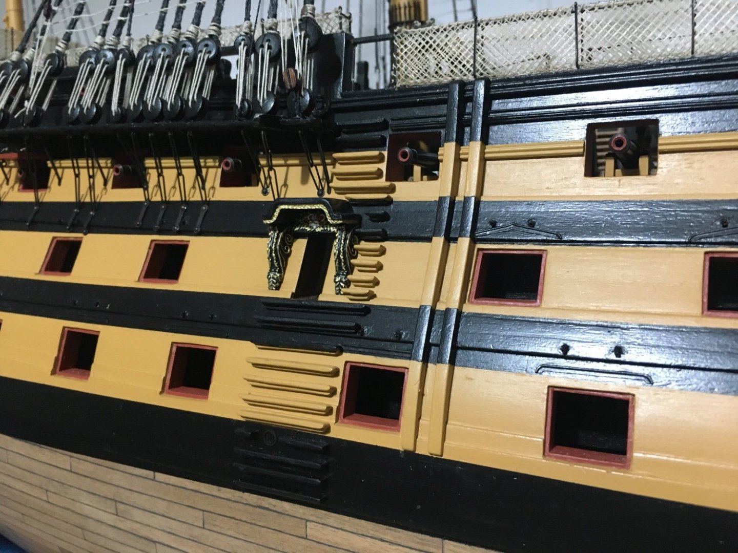
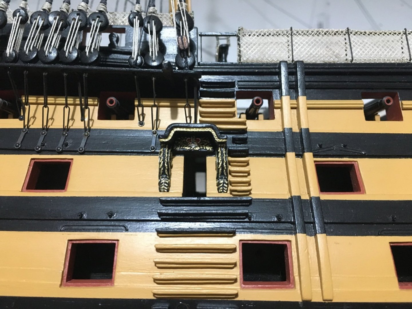
A small update, I fitted the side entry ports which I had prepared some time ago. Robert
- 527 replies
-
- 8
-
-
- caldercraft
- victory
- (and 1 more)
-
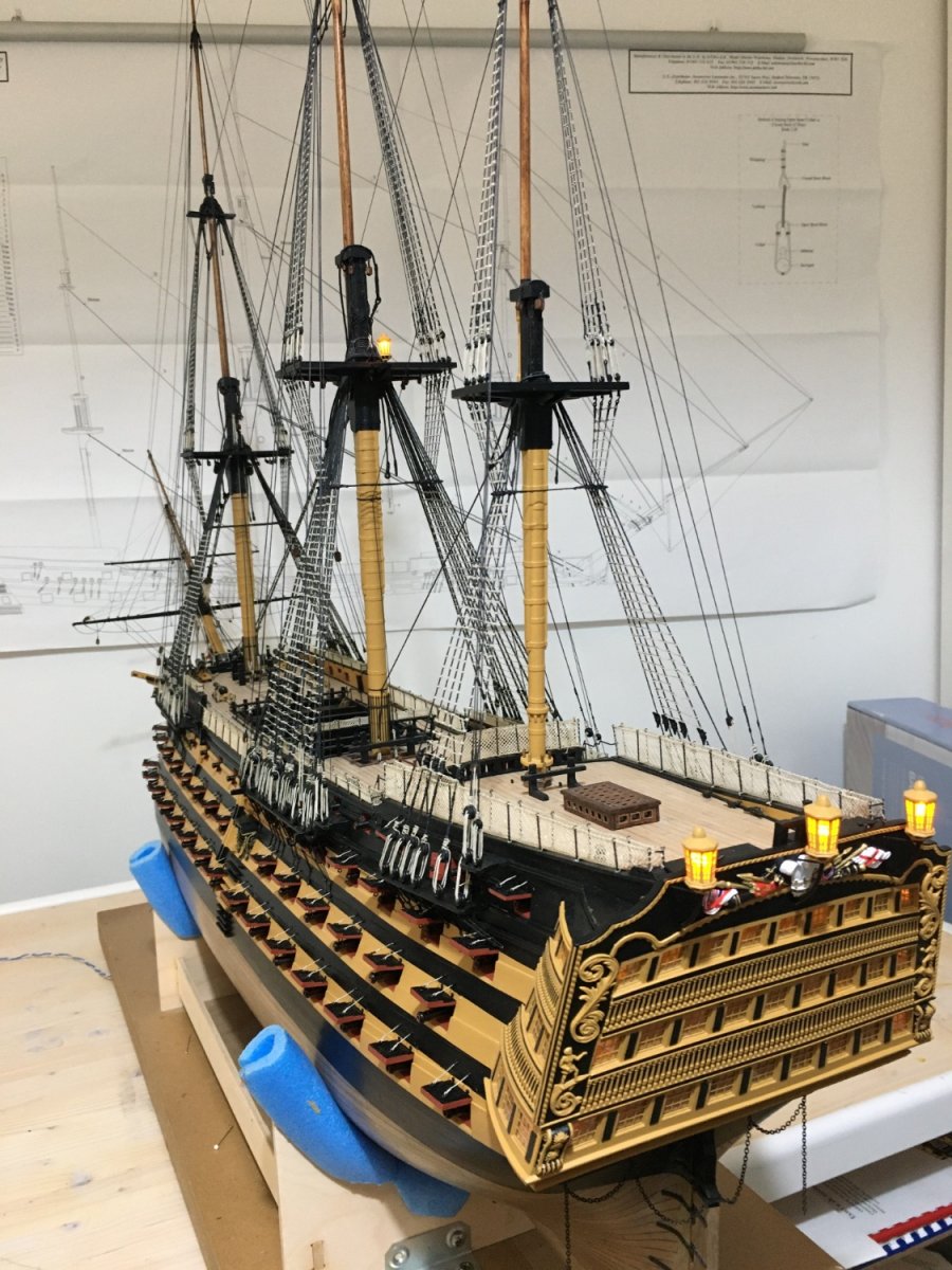
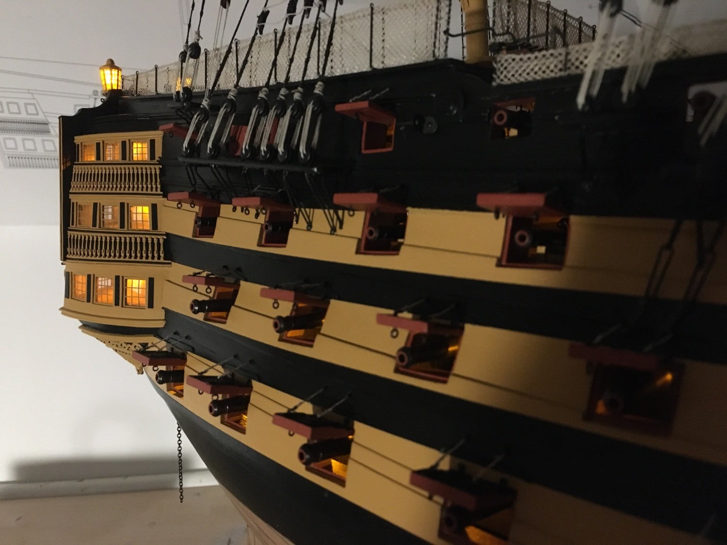
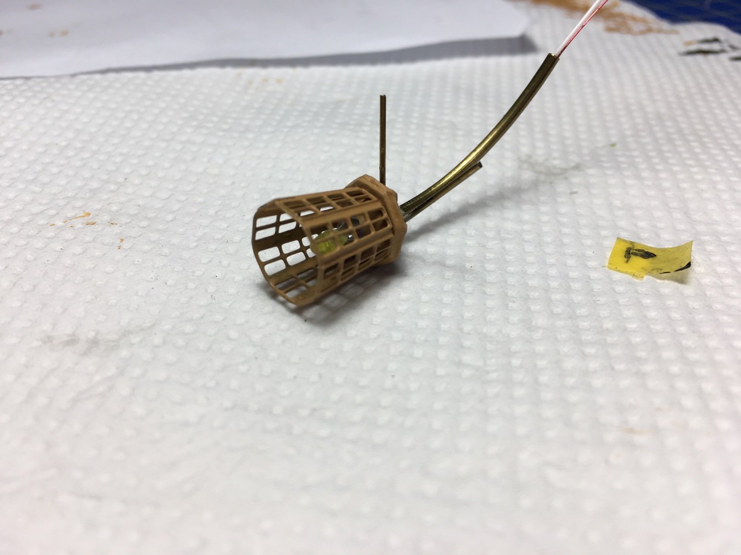
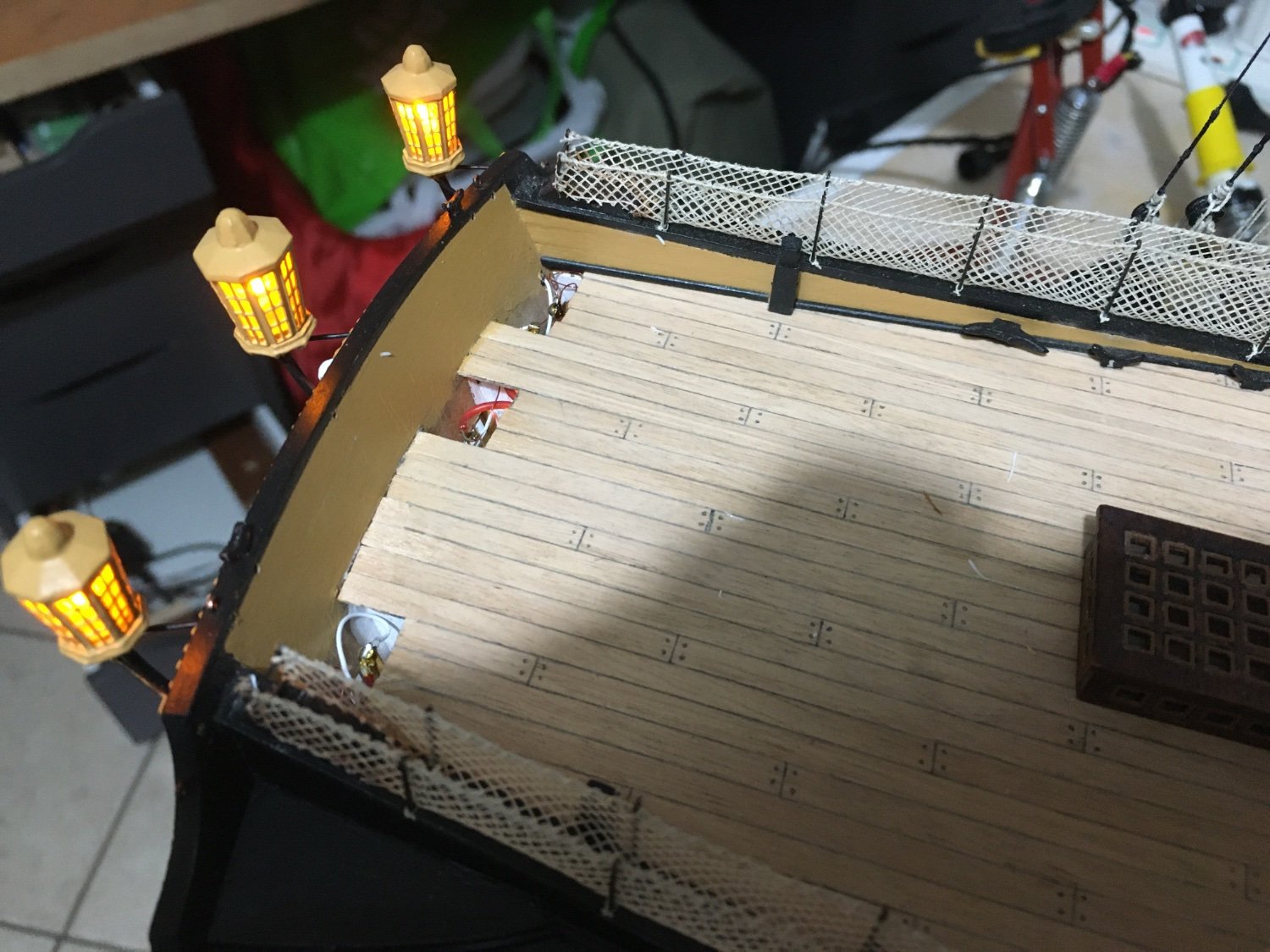
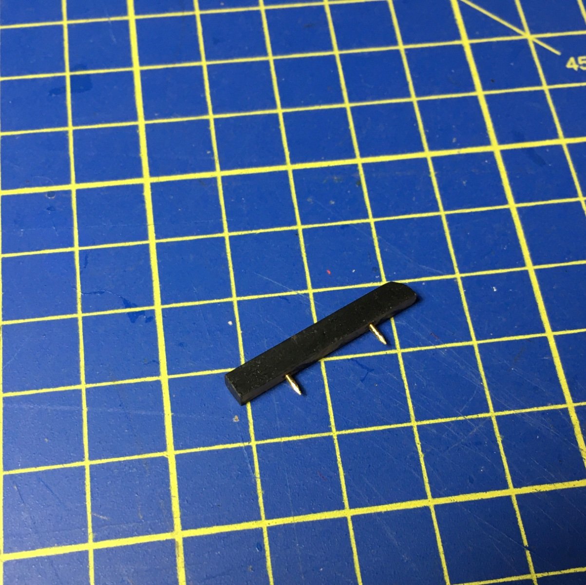
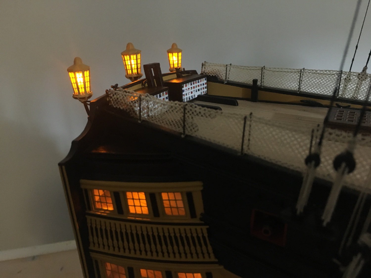
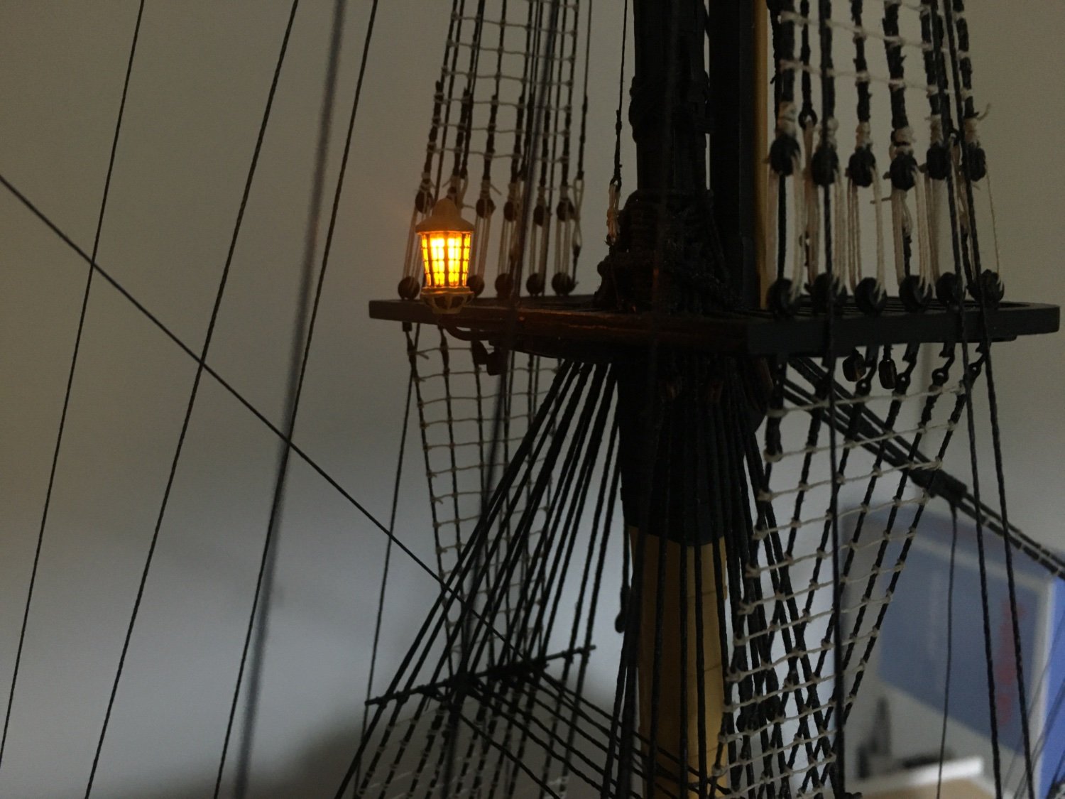
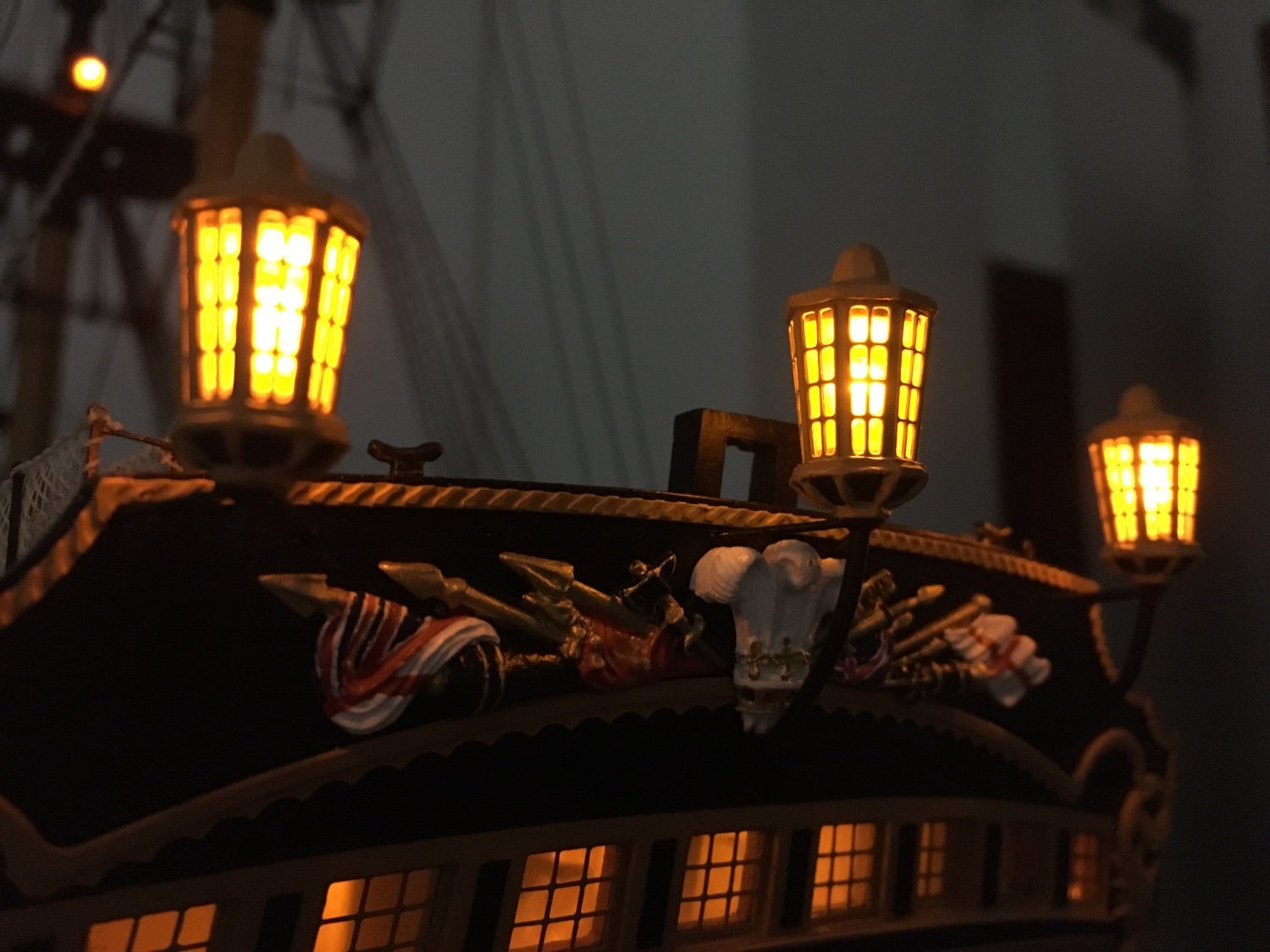
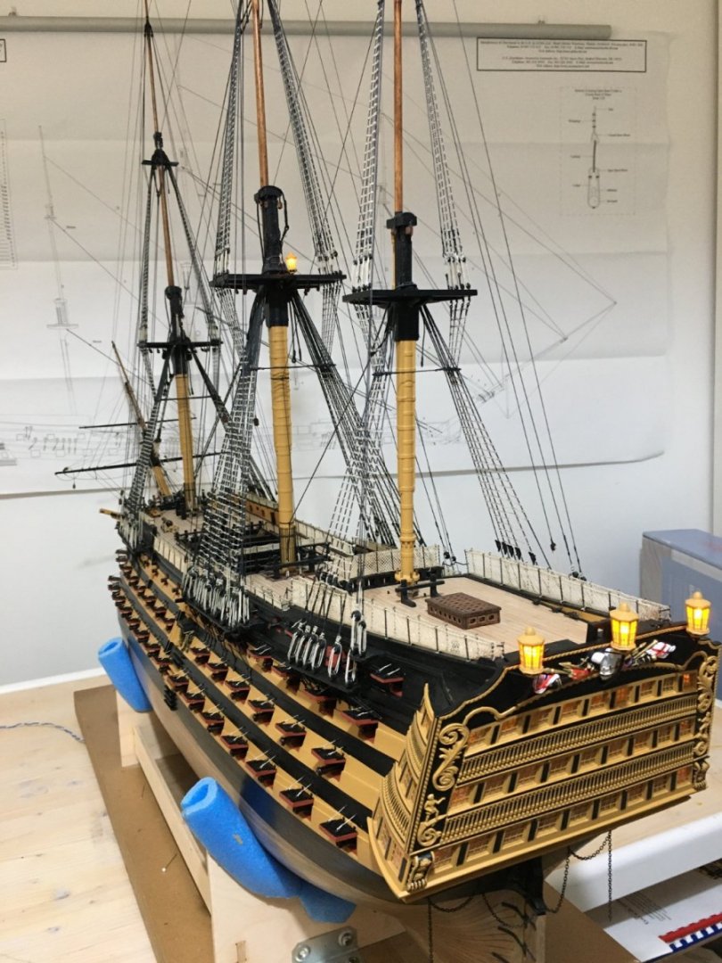
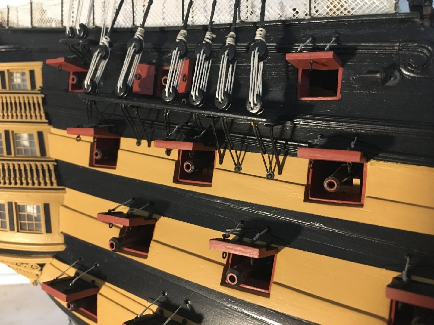
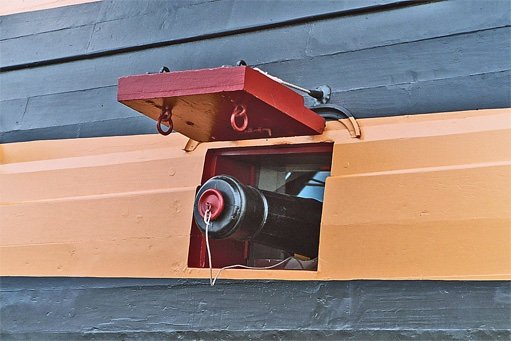
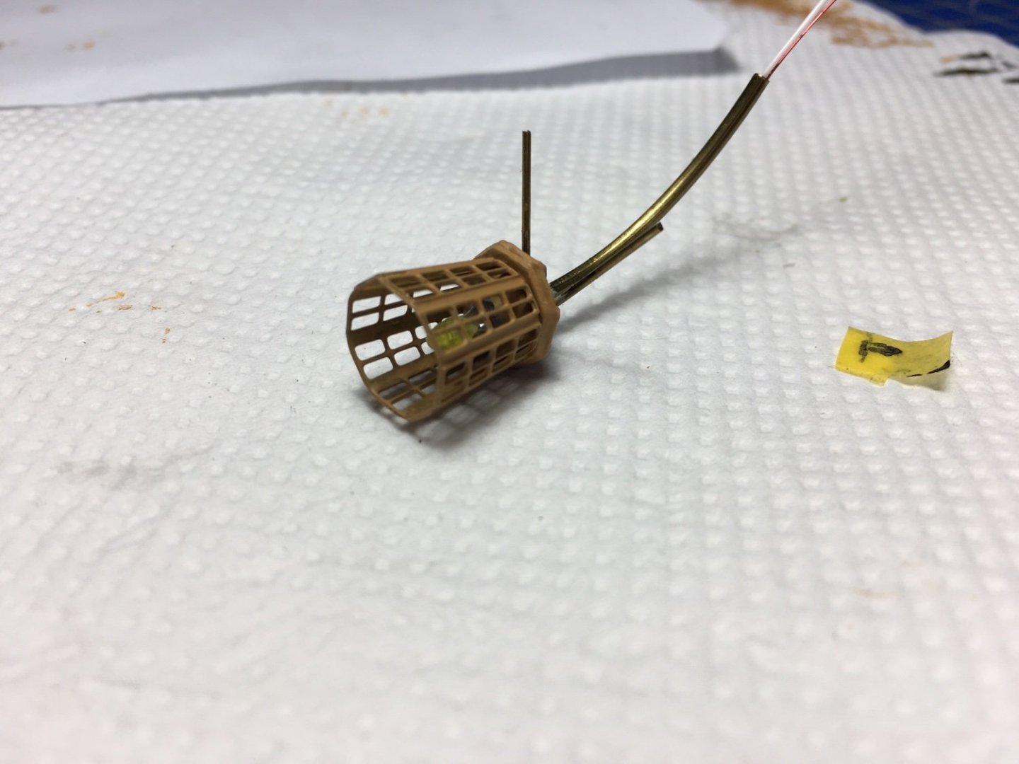
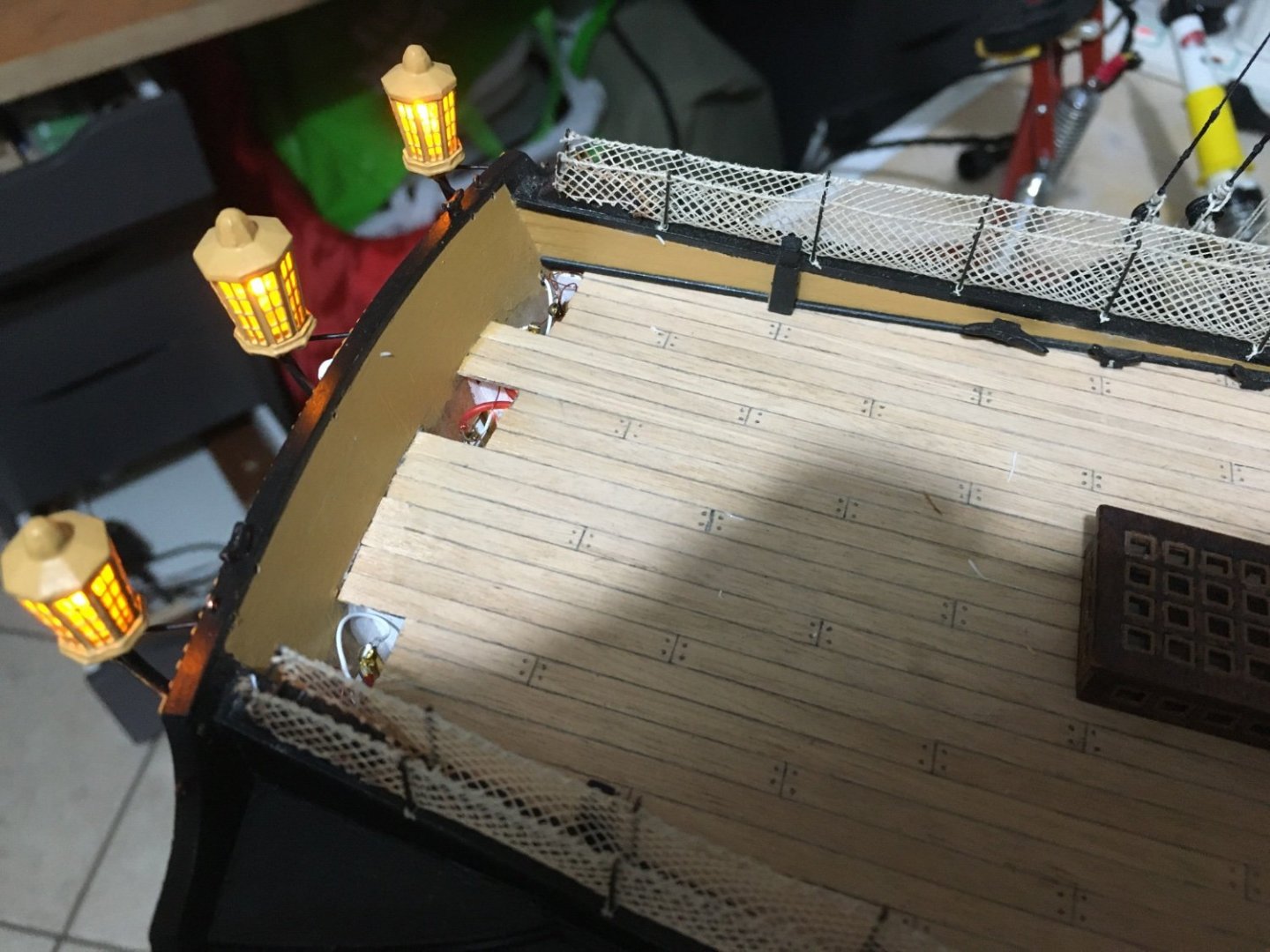
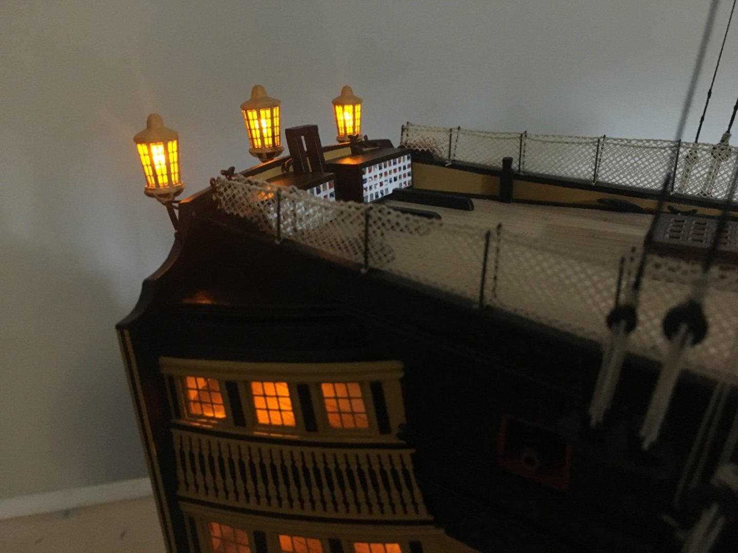
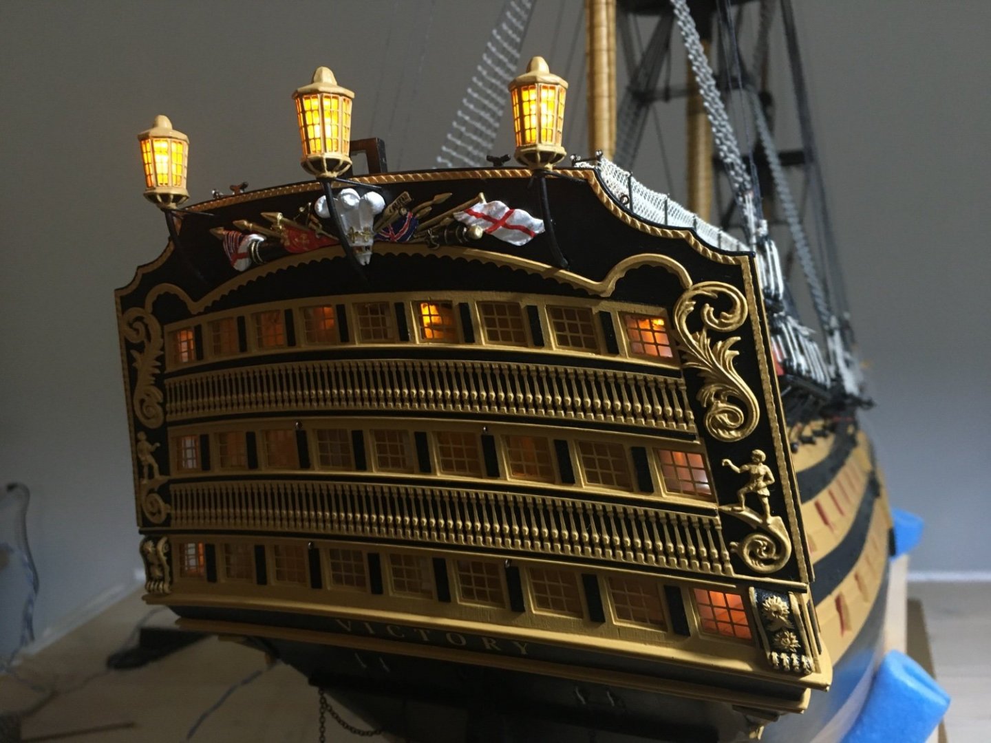
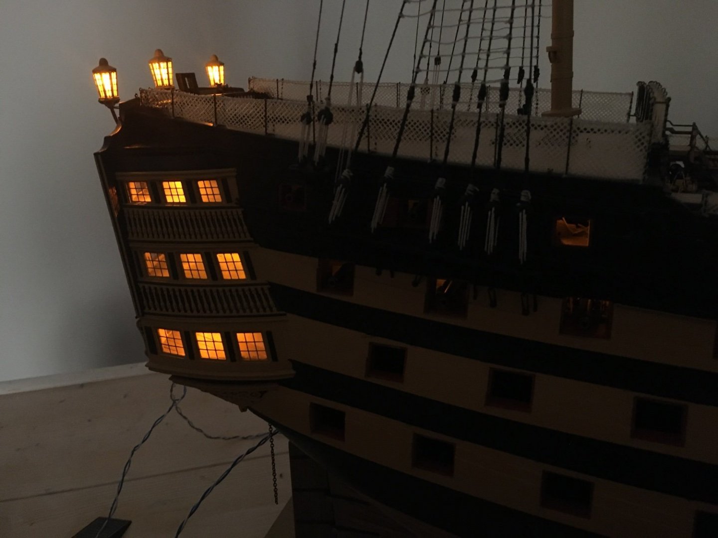
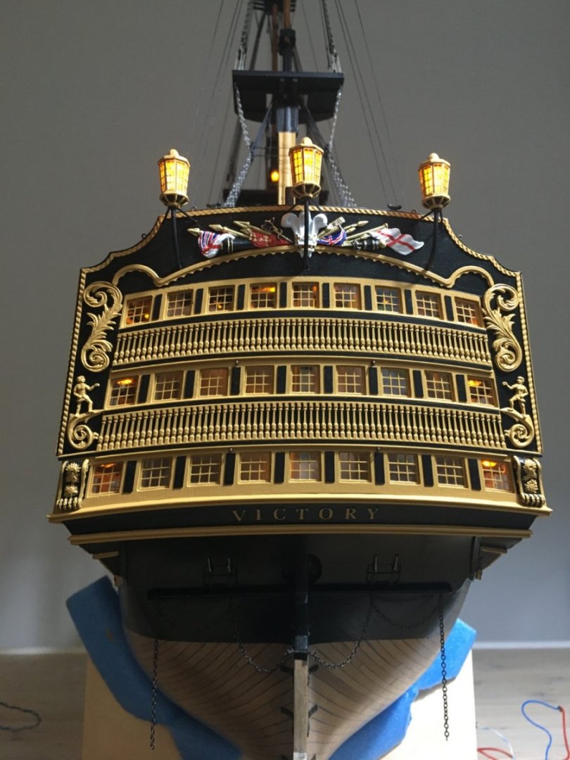
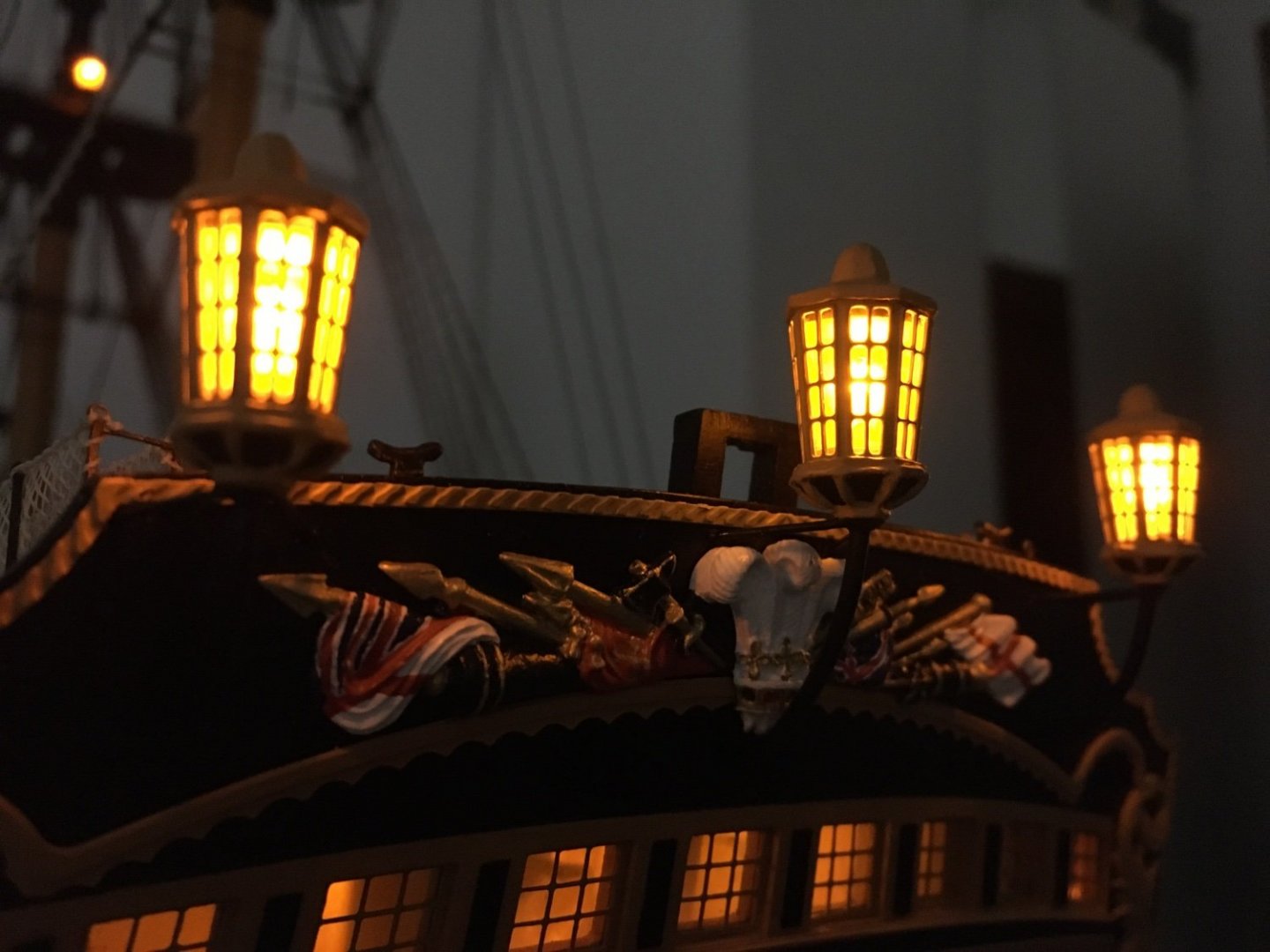
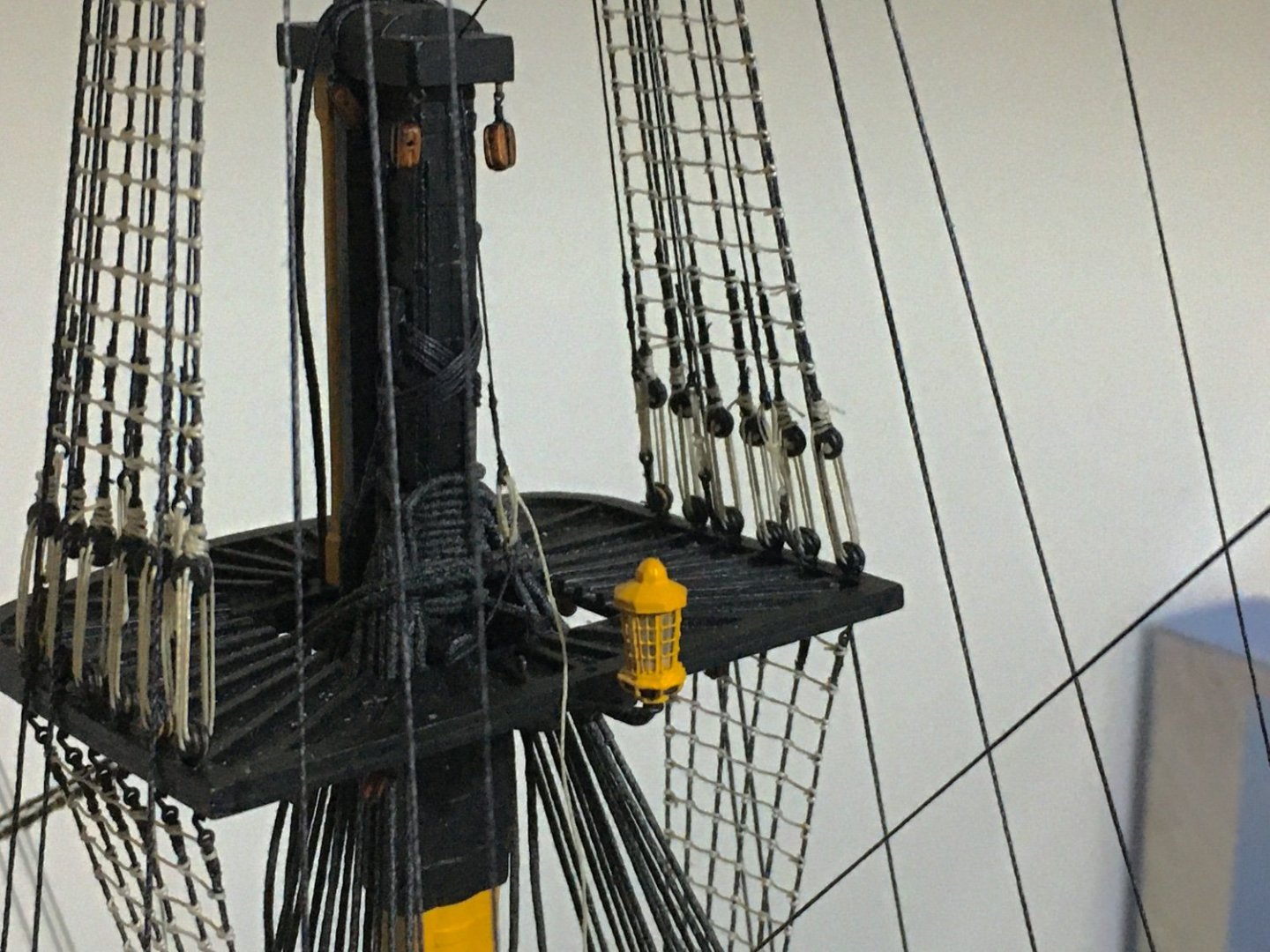
Thank you Malcolm, and thank you all for the likes. Stern lanterns in place. I was very eager to fit them and see how they look. I left them up to now to avoid nocking any of them while doing the rigging. But now I had to ship them as otherwise it would be very difficult to wire and solder them in place with more rigging in the way. I had already prepared the brass work and wiring of the LED's inside the lanterns. I painted the three parts, that is the base with the brass arms and led's, the cage and the top and assembled them. Soldered the wirer from the open spaces I left on deck and checked that they are working fine. Flag lockers in place and covering the openings I left for soldering the lanterns wiring. I did not glue the lockers so that I can still have excess to the soldered wires if need be. The outer transom knees kept the lockers in place. Instead of gluing the knees I fitted two cut nails in their underside and pinned the knees in corresponding holes on the deck so I can easily remove them. Lanterns and stern windows all lit. Lantern on main mast top. So basically now I have finished all the lights and wiring. It did involve quite some work, and to be honest at first I was a bit hesitant if I should go for the lights or not. But now I am glad I decided to go for it, I think the result was worth the extra effort. Robert


- 527 replies
-
- 11
-
-
-
- caldercraft
- victory
- (and 1 more)
-
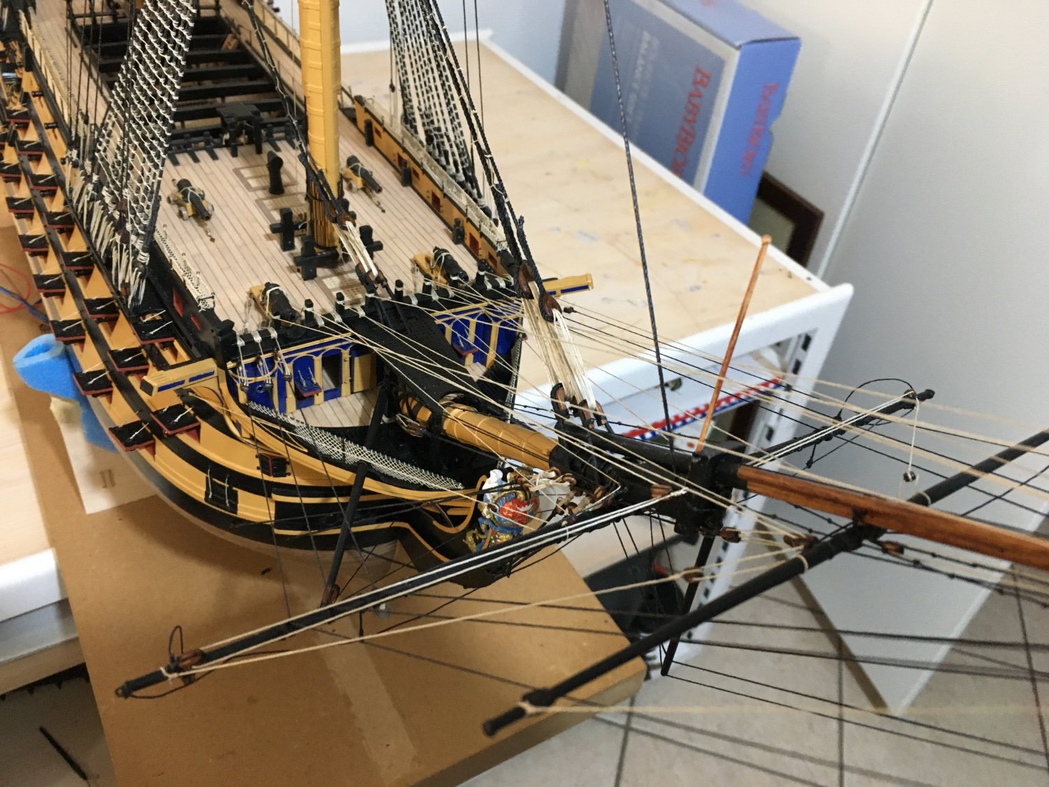
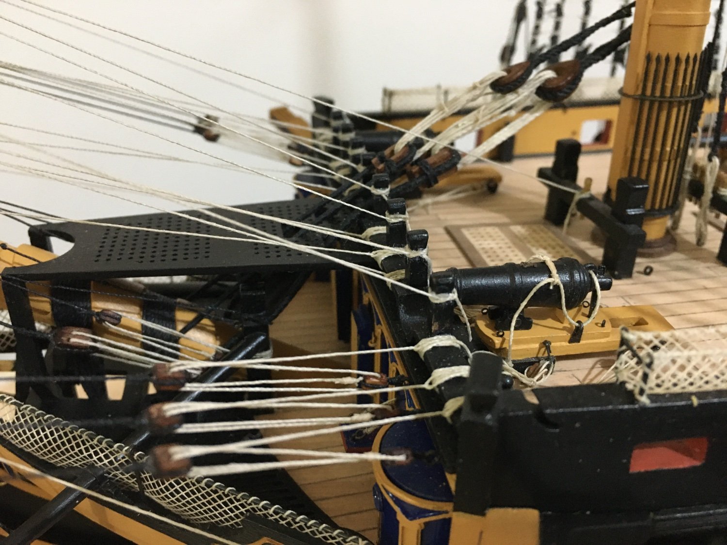
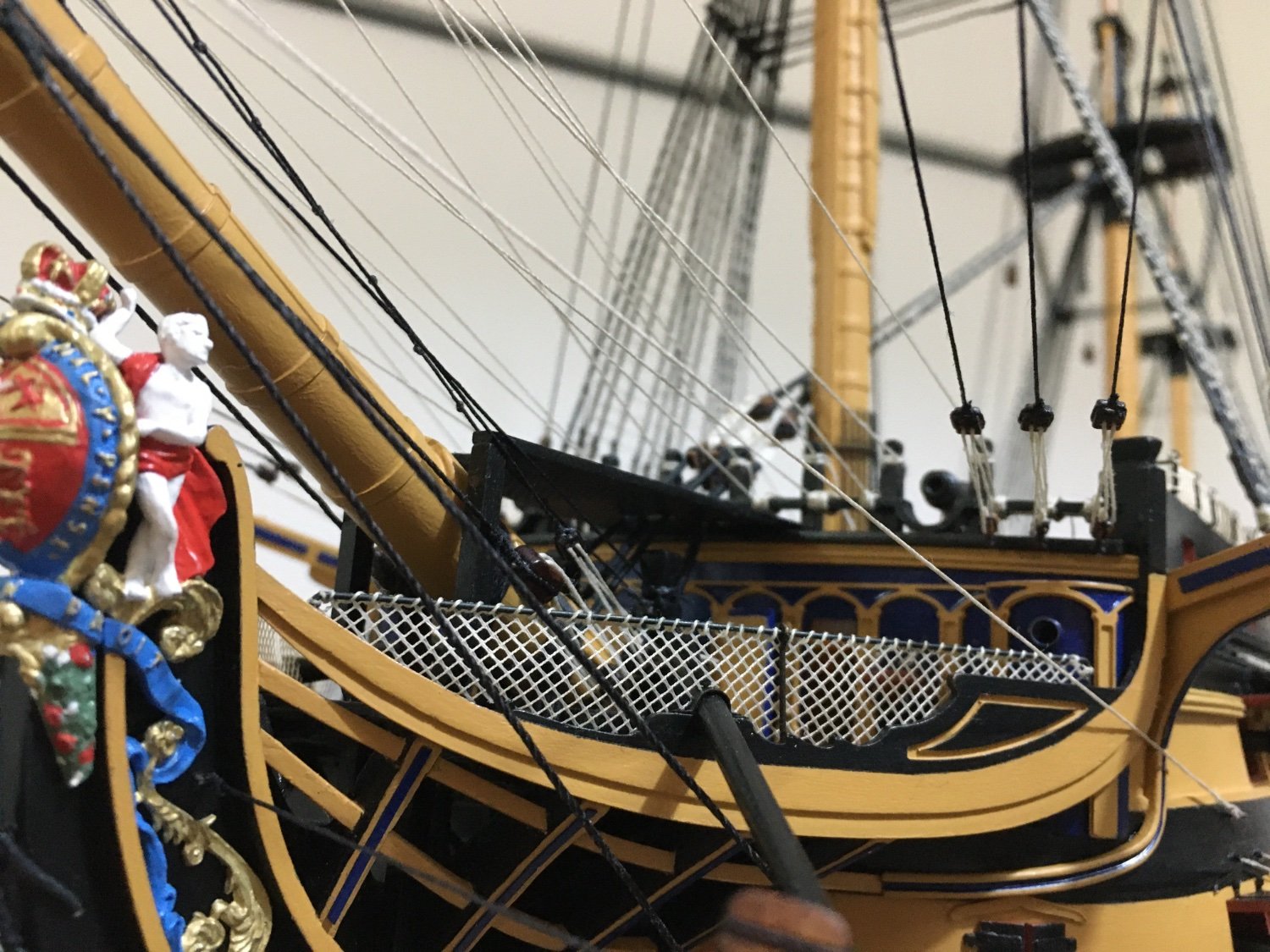
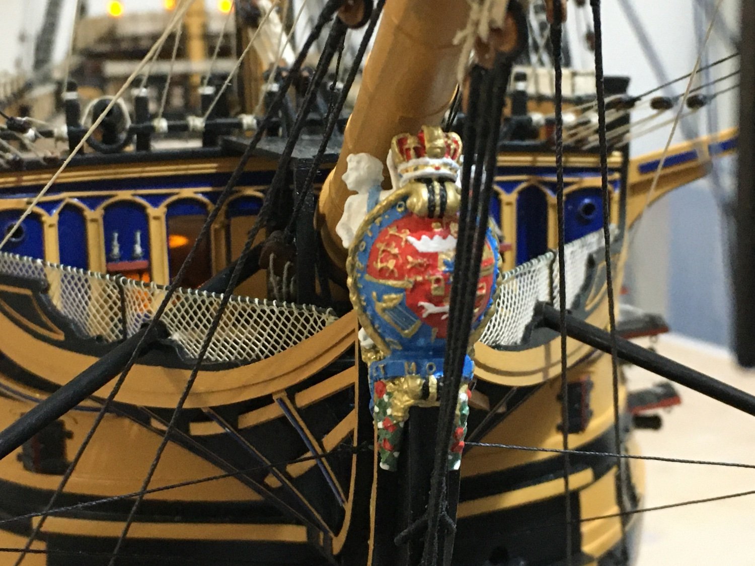
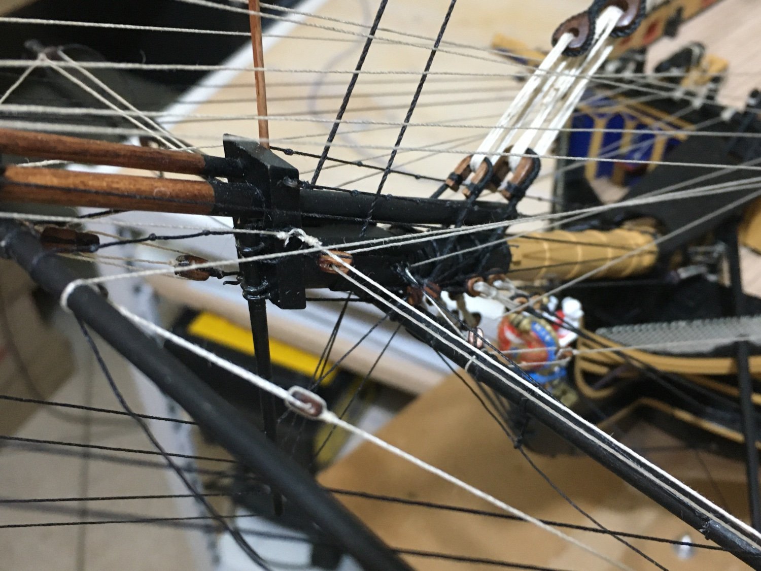
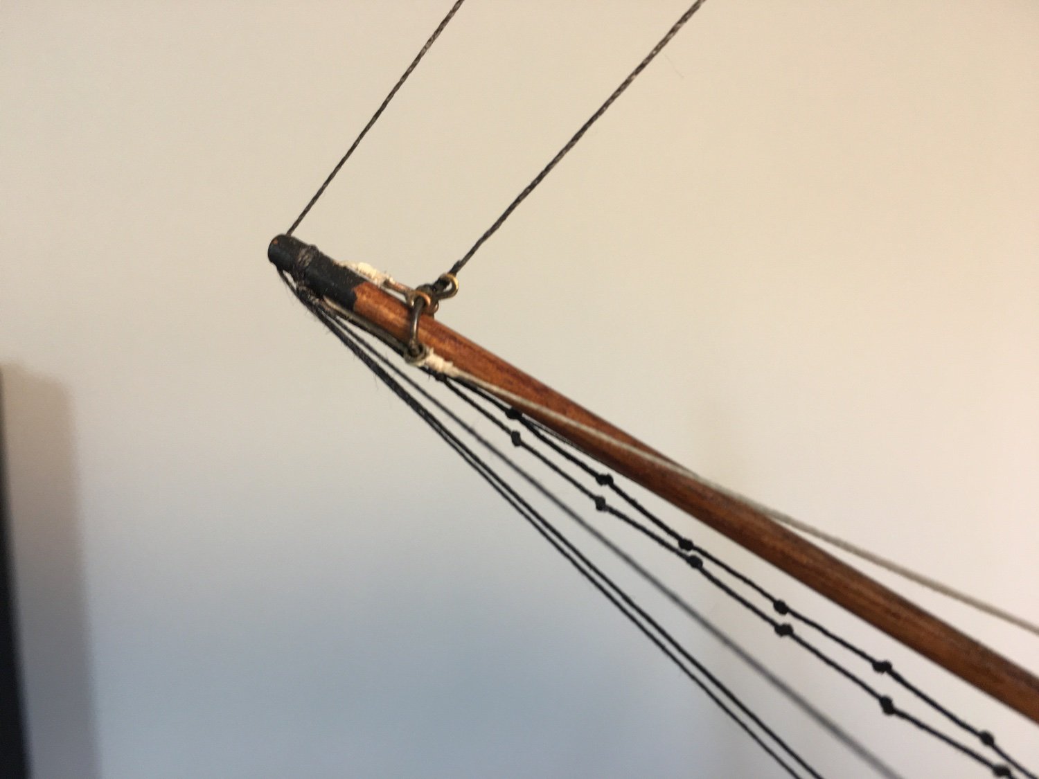
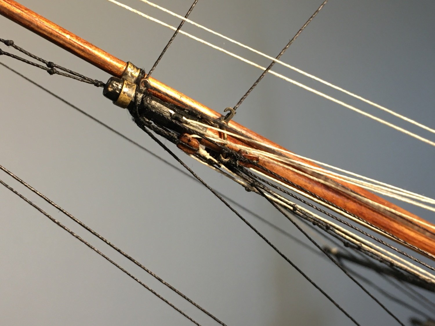
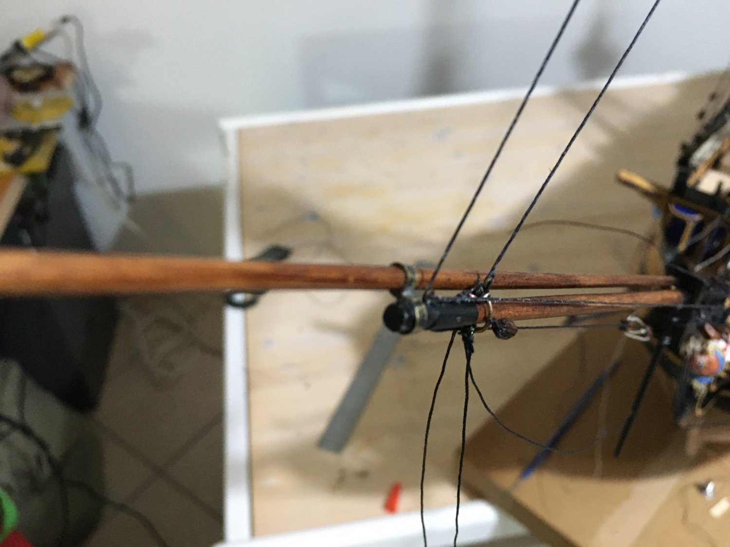
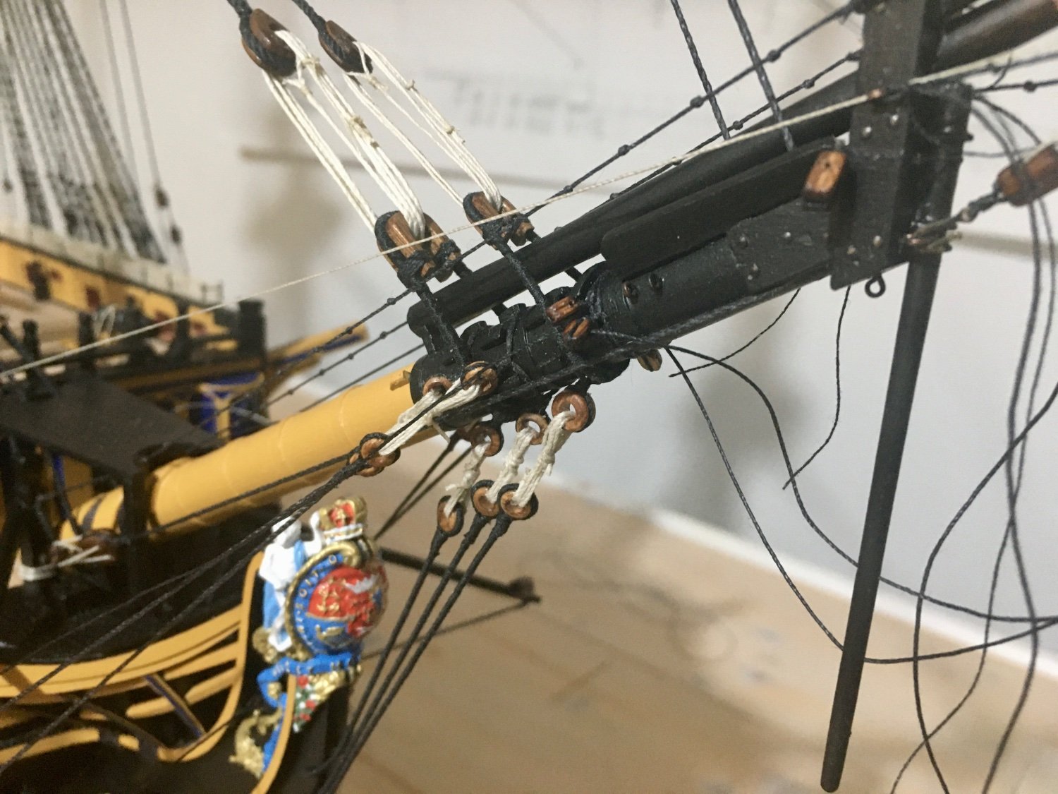
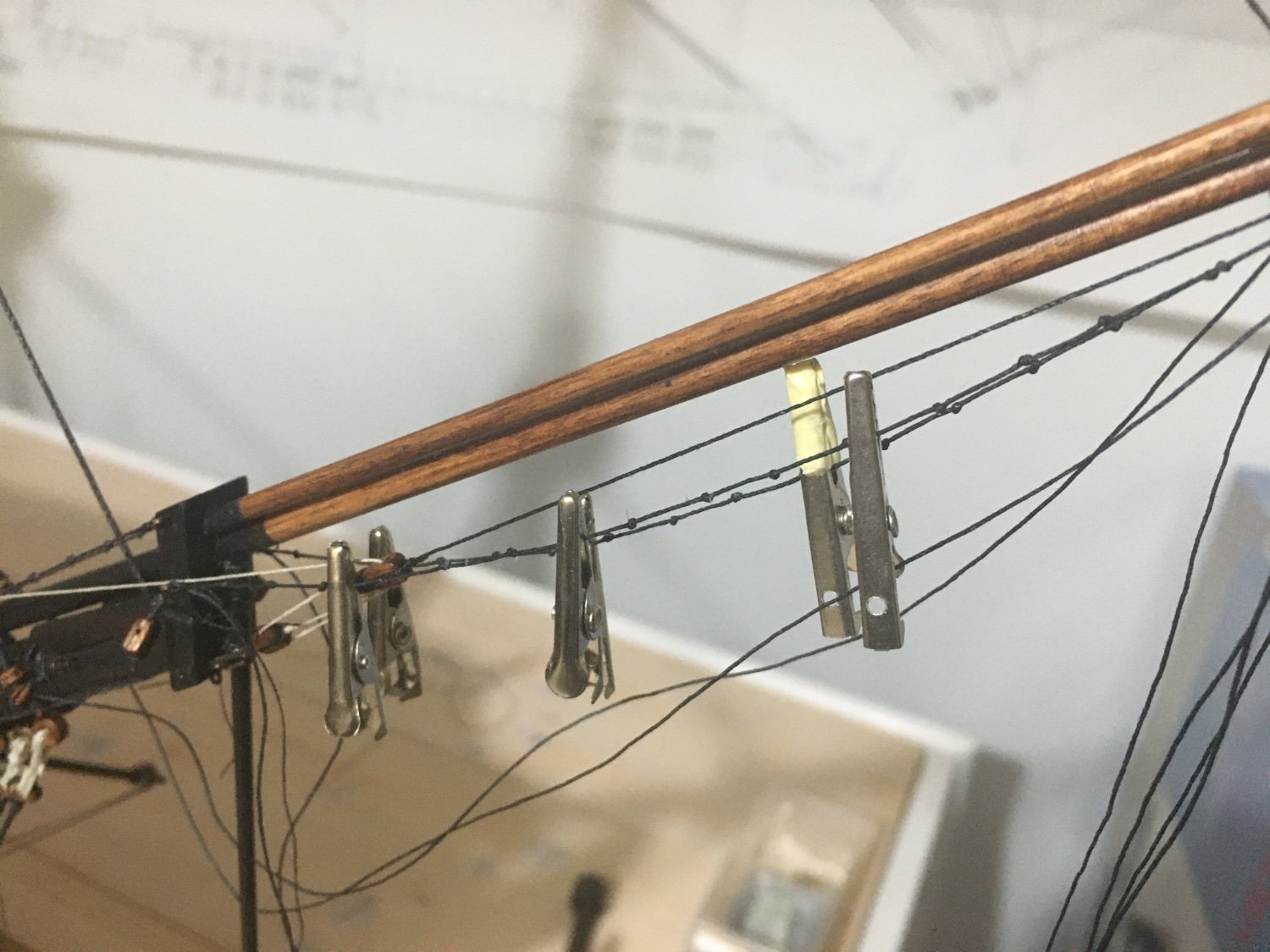
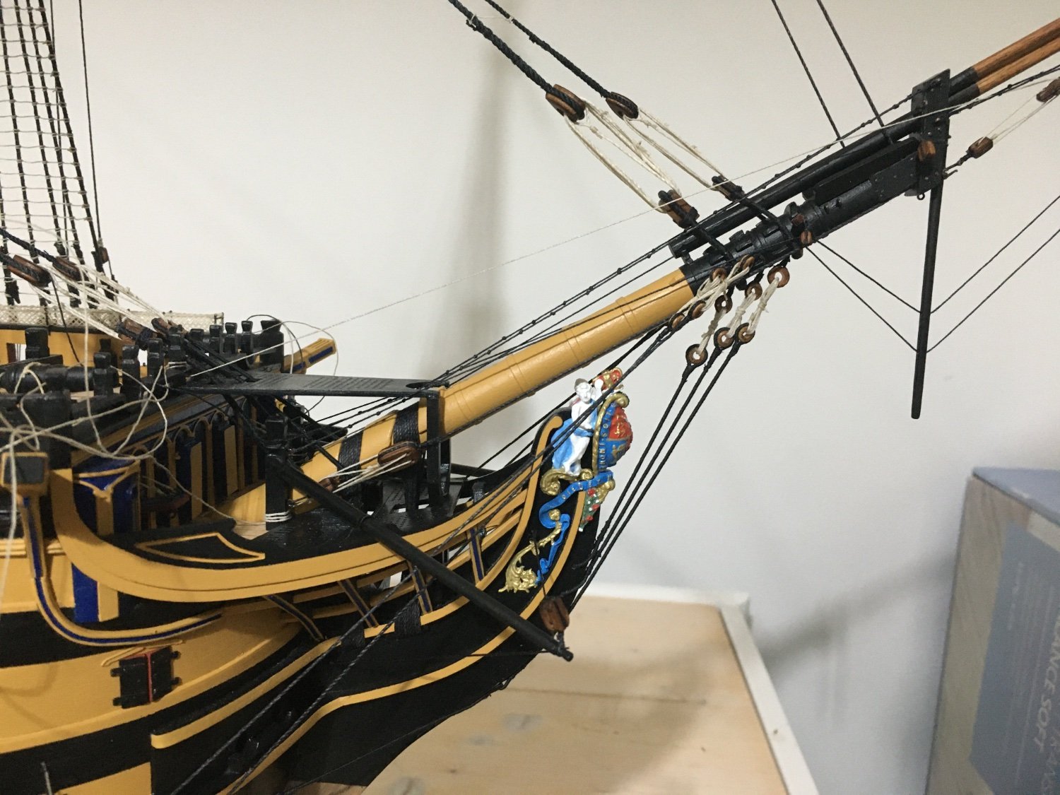
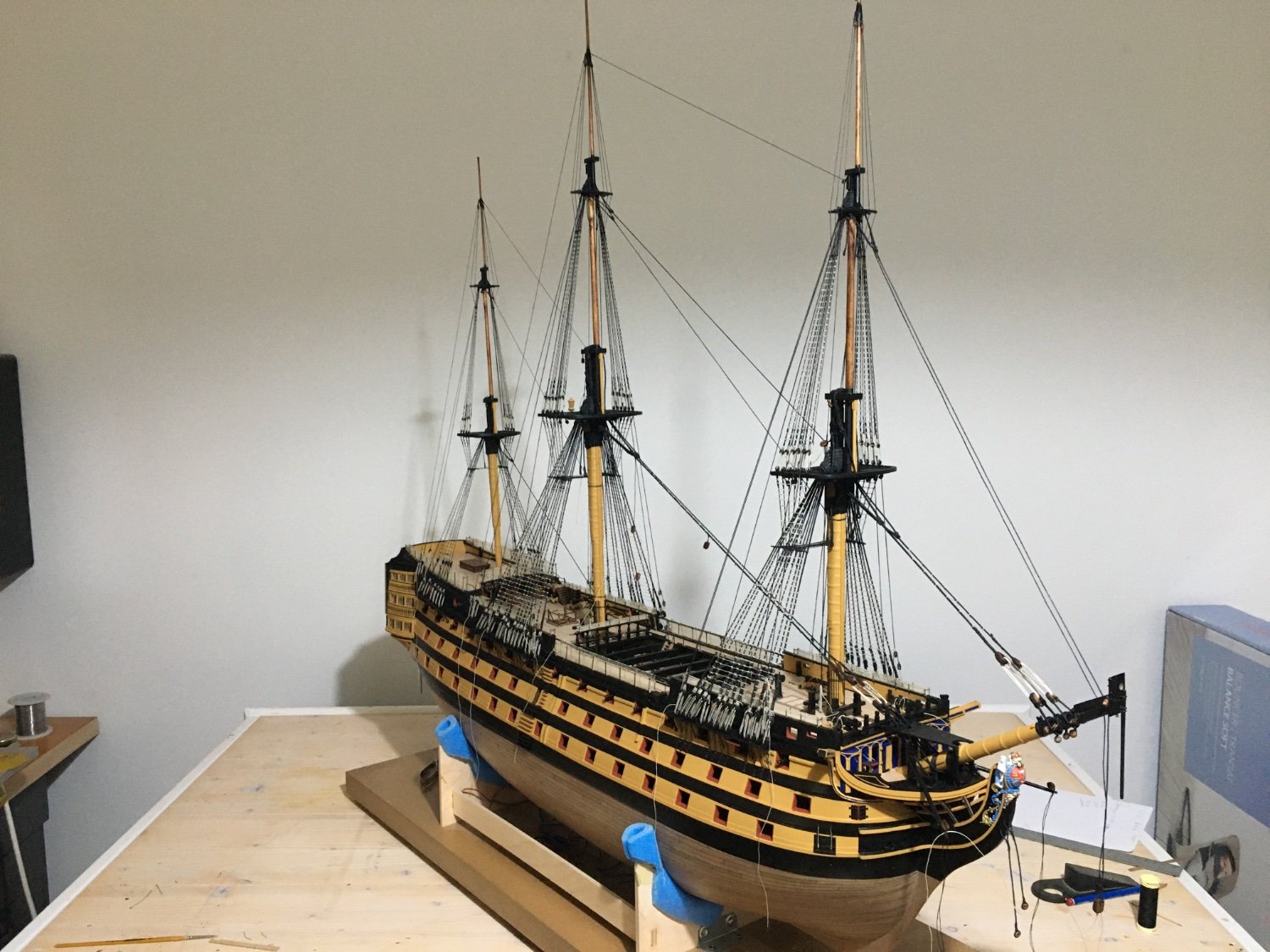
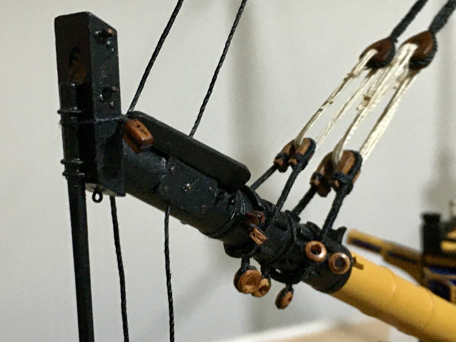
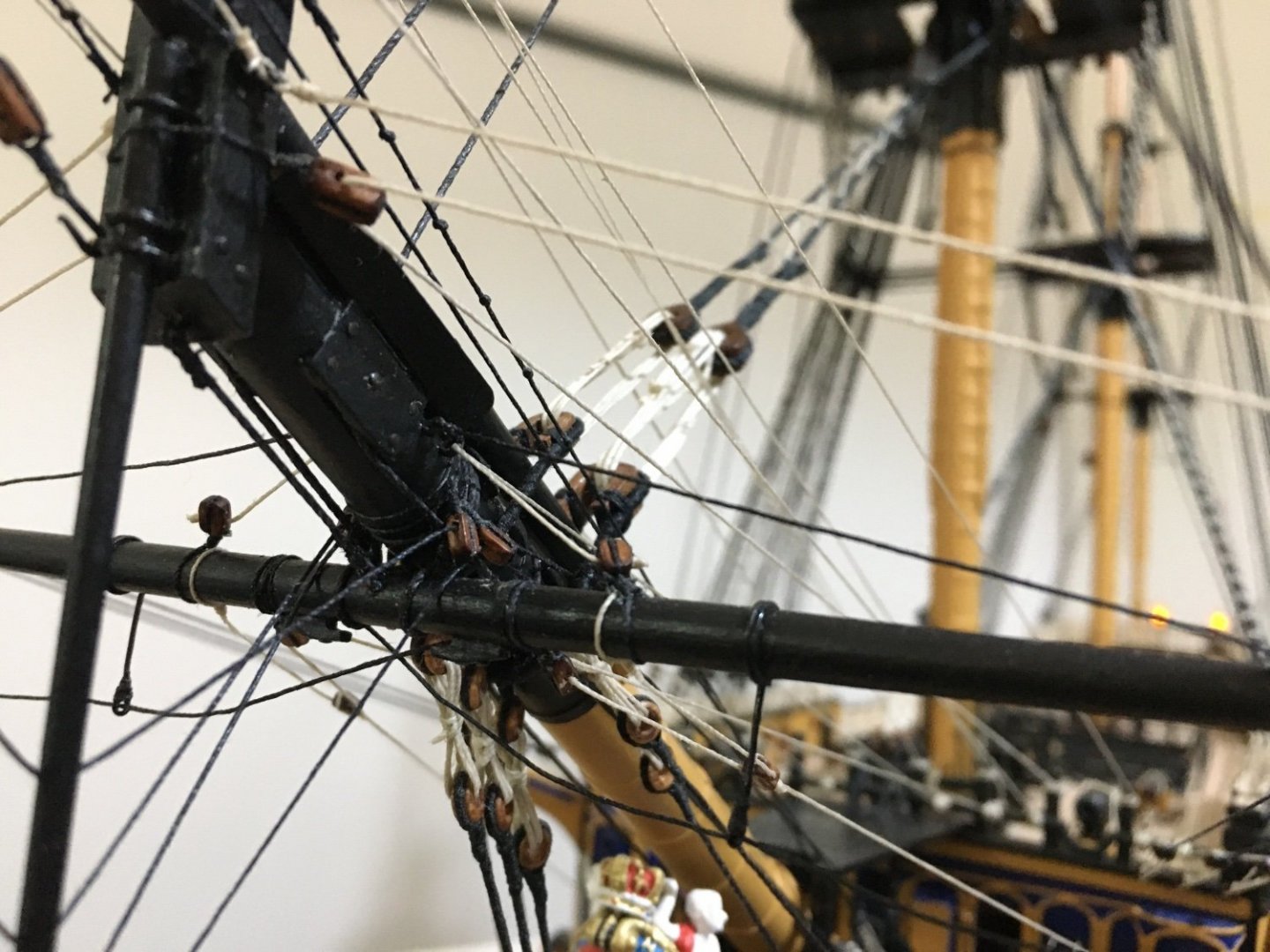
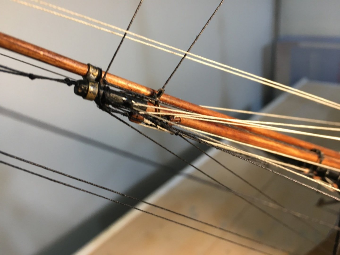
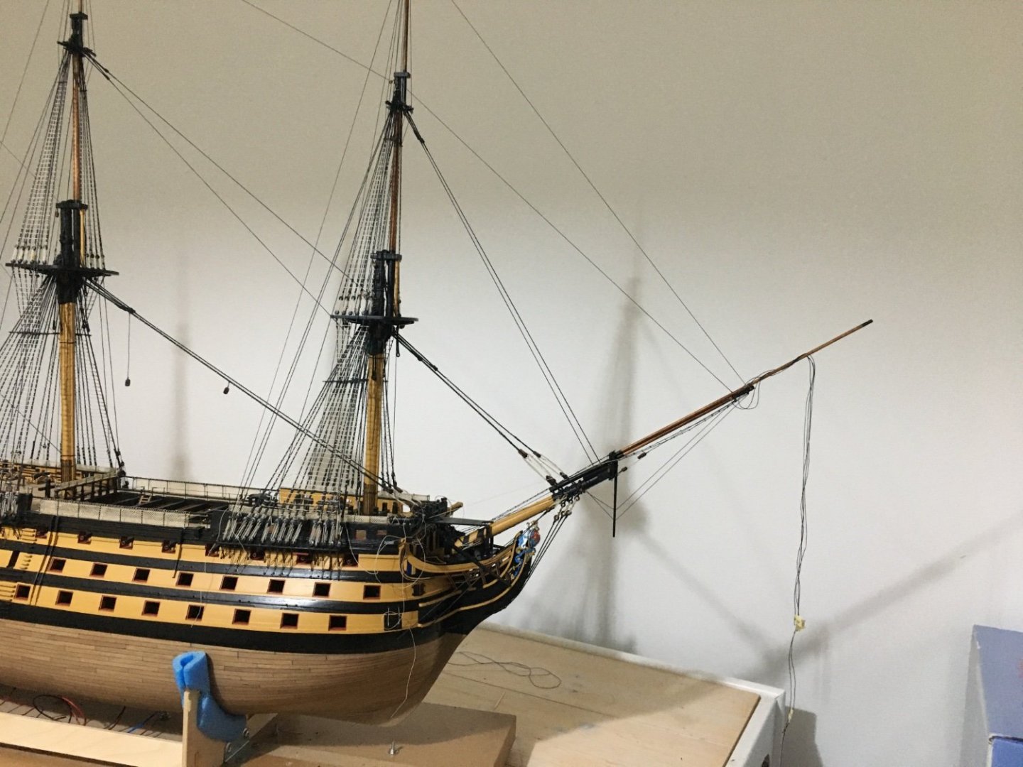
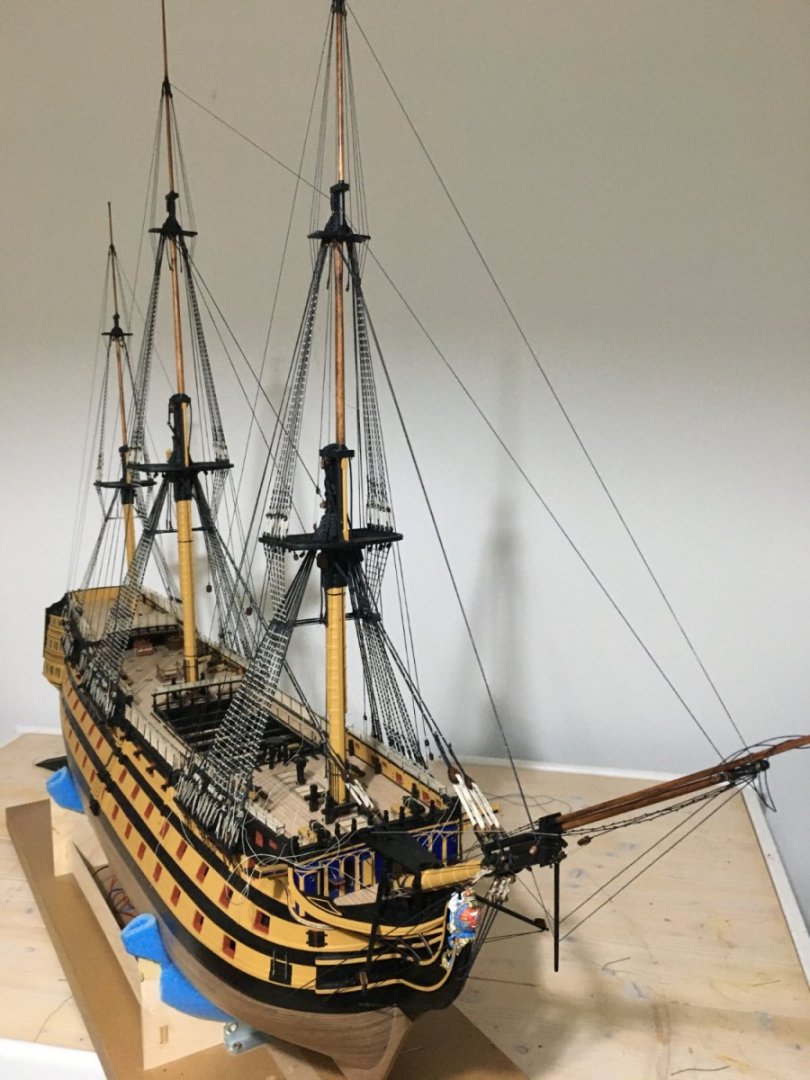
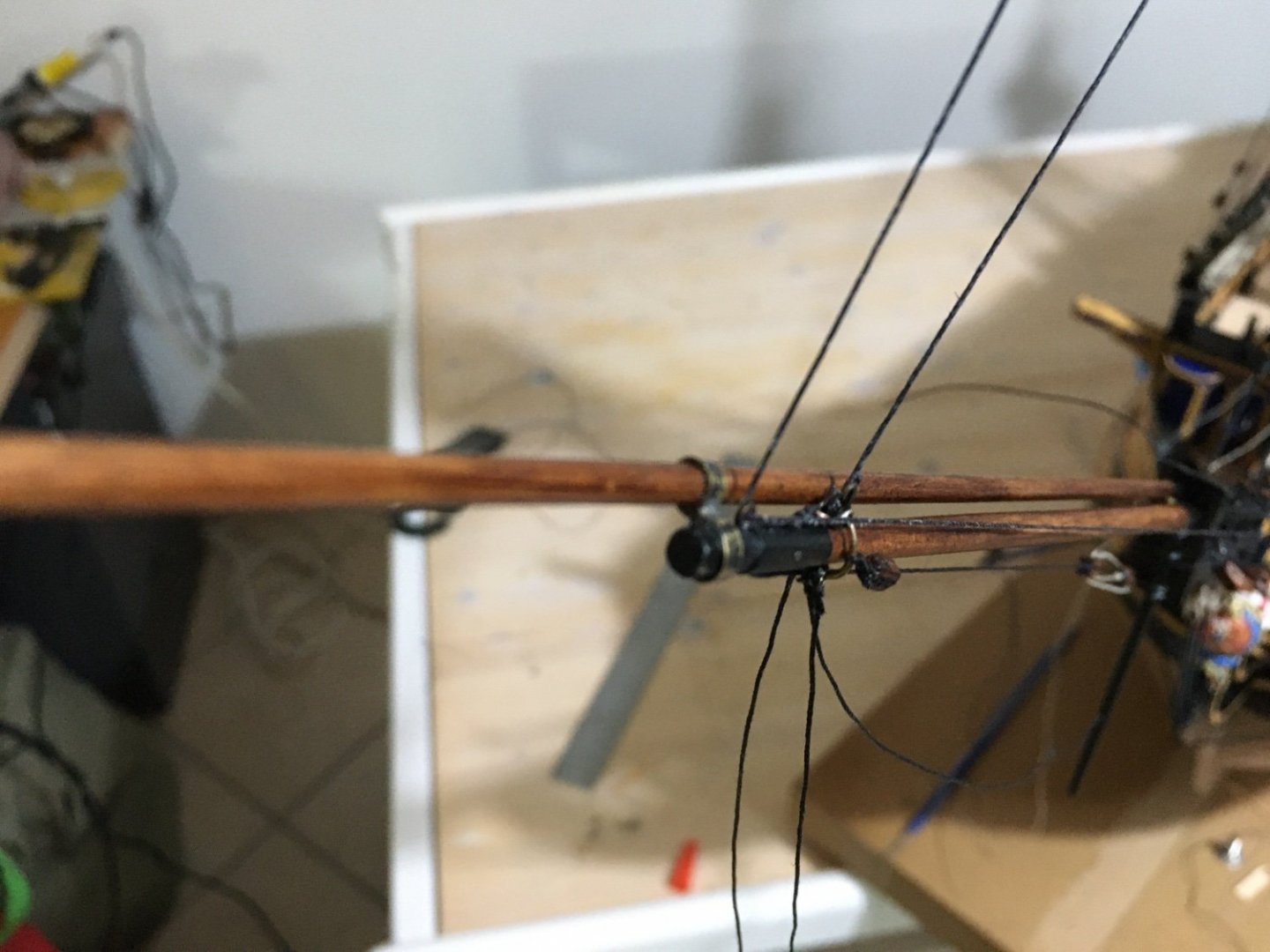
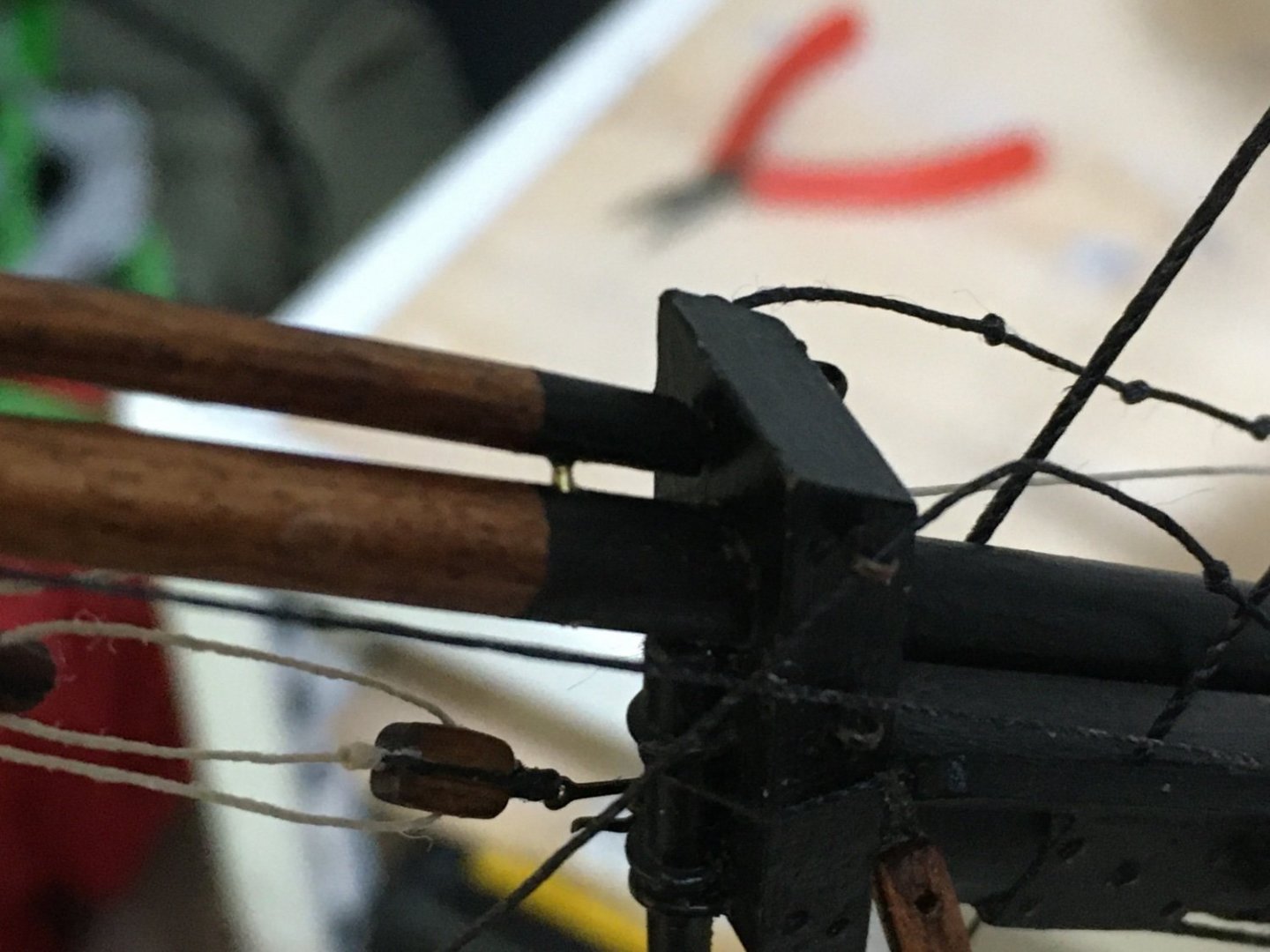
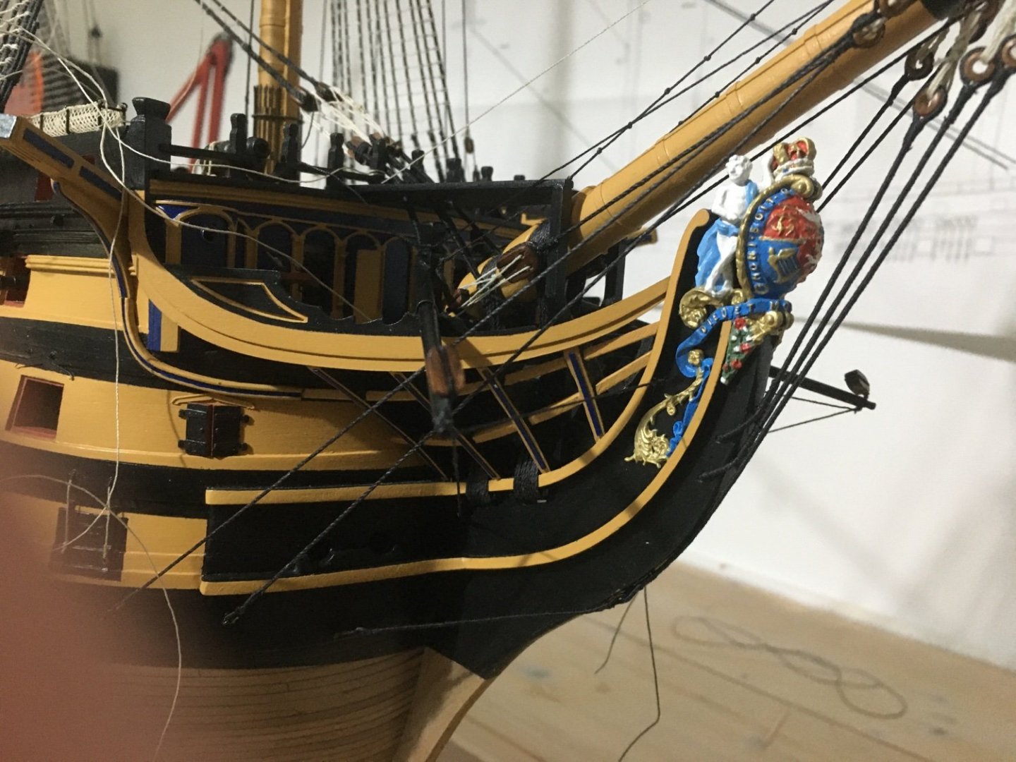
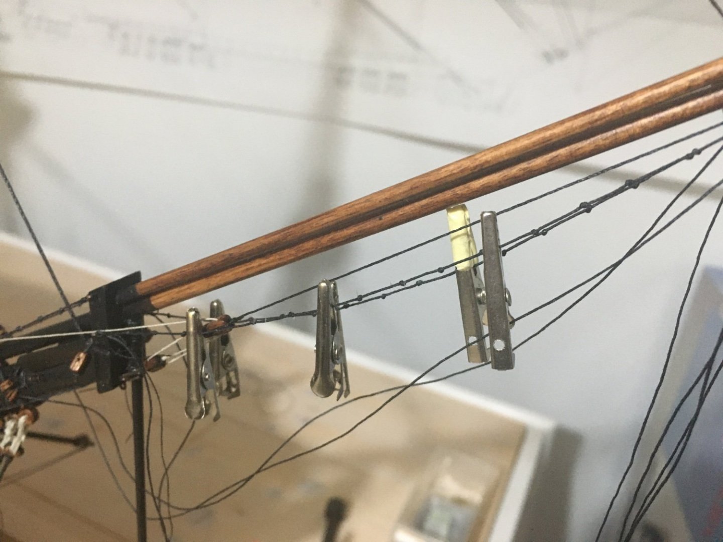
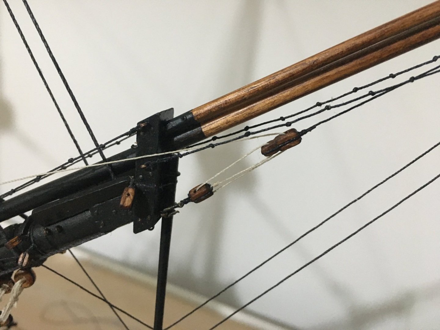
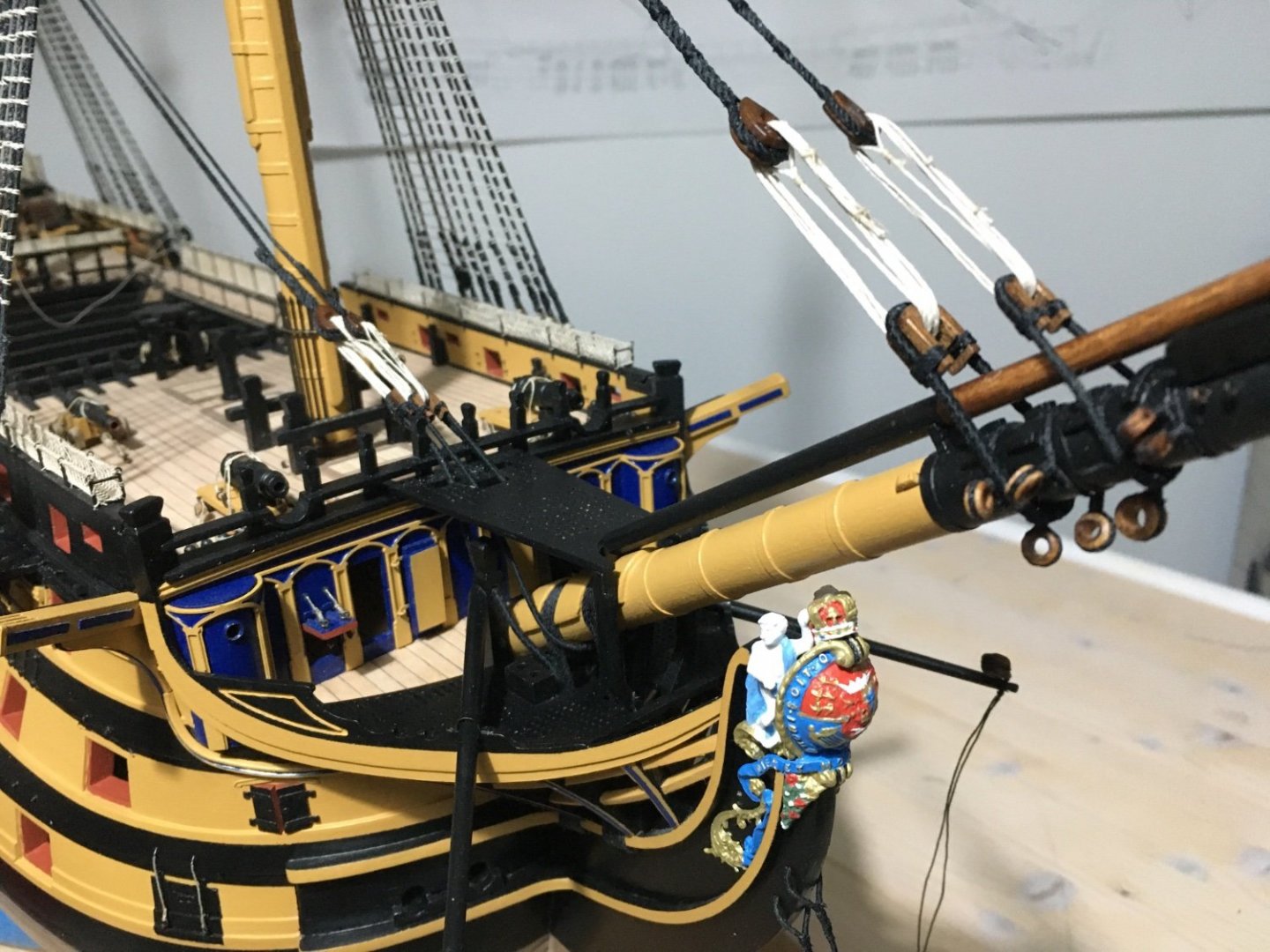
Proceeded with more work on the standing rigging, backstays and bowsprit. Fitted the Jiboom in place and after inserting the traveller also fitted the flying jiboom with the brass rings I had prepared earlier. To reinforce and keep in place the flying jiboom at the back end I drove a piece of brass road trough the flying jiboom and the jiboom. Later I painted black so it doesn't show much. Finished the bowsprit shrouds and the Boomkin Stays. You can also notice the Man Rope which run from a copper eyelet on the side of the bowsprit cap to an eyelet on the knighthead. As I had added the travellers I had to divert quite a bit from the instruction manual for the jiboom and flying jiboom rigging. Part of the rigging which in the manual were indicated to be secured to the jiboom end had to go to the traveller. Also I included some more detail which was omitted in the manual. I referred for these details in Longridge. You can notice the still unrigged travelling guys seized to a thimble in the traveller and the guy pendant seized to the notch in the end of the jib. They are to be rigged later as they have to go through eyelets in the spritsail, still to be shipped. The jibboom horse also in place. To give it that sagging effect I wetted the horse with diluted PVA glue and put some clips along it as weights until it dried. Here you can see the tackle for the Jib Outhauler. Long tackle block made by attaching two blocks together. The rope for the long tackle block is first secured to the shackle on the traveller, then passed through a hole (representing a sheave) in the jibboom and then the long tackle block seized to it. Inner and outer martingale are also in place. The martingale ends and some other rigging although they are tied to there respective places, they are not secured, glued and trimmed for the moment, in case I have to loosen them for other rigging. Now before I start fitting the yards and the driver gaff and driver boom on the stern I think I better carry on fitting the stern lanterns and the gunport lids as otherwise the yards will be too much in the way. Robert


- 527 replies
-
- 10
-
-
-
- caldercraft
- victory
- (and 1 more)
-
Beautiful rigging Tom. You make me wish I had a go at making my own ropes on my Victory. At that time I thought it is too much work, but I can see it is a rewarding process. Keep it up. Robert
-
Beautiful detailed work Jason. That extra attention to detail with of course your craftsmanship makes all the difference in a model build. Just awesome. Robert
-
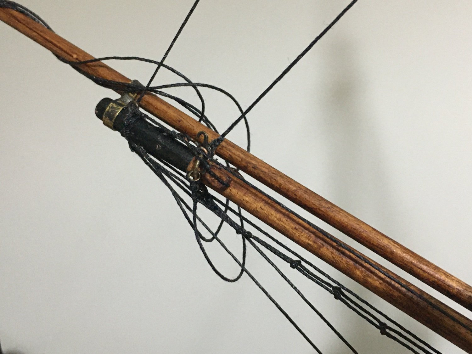
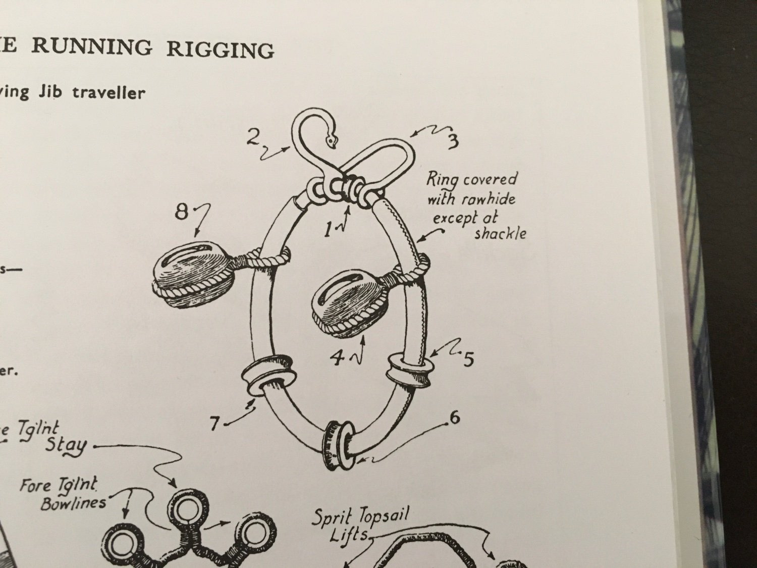
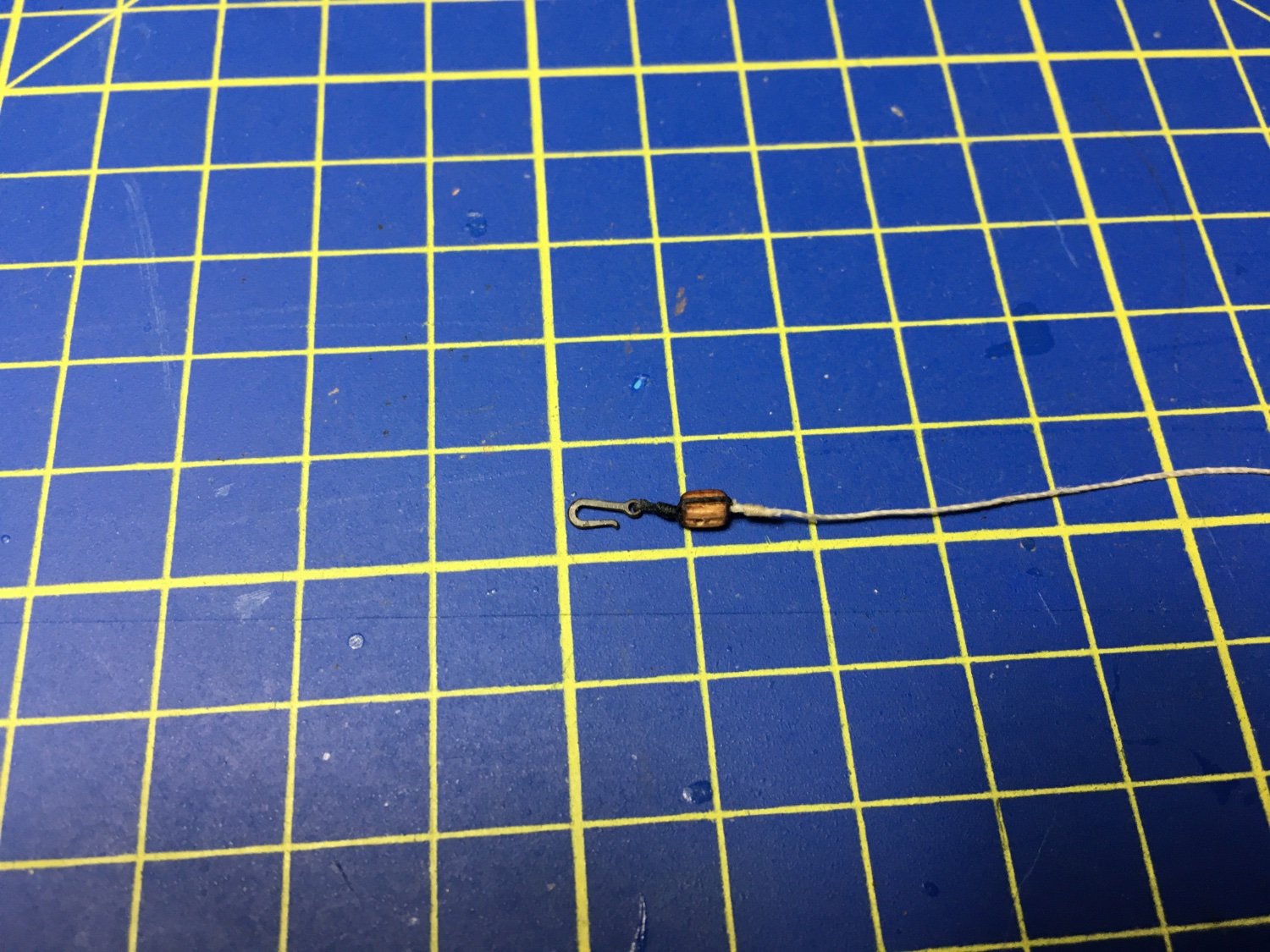
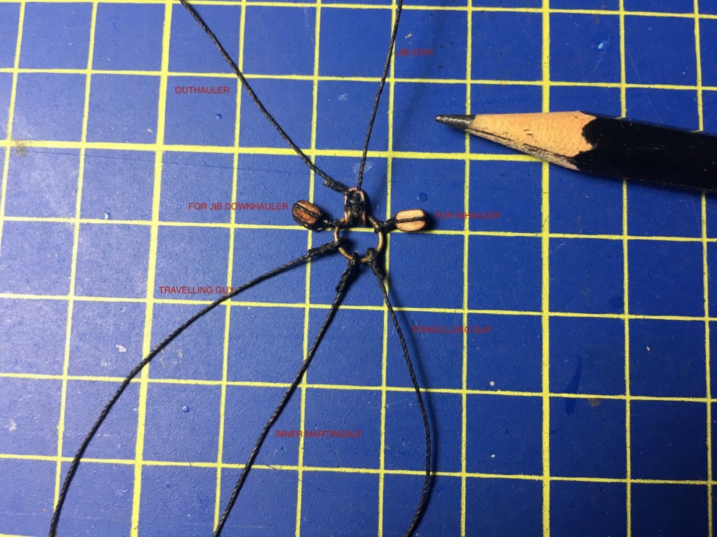
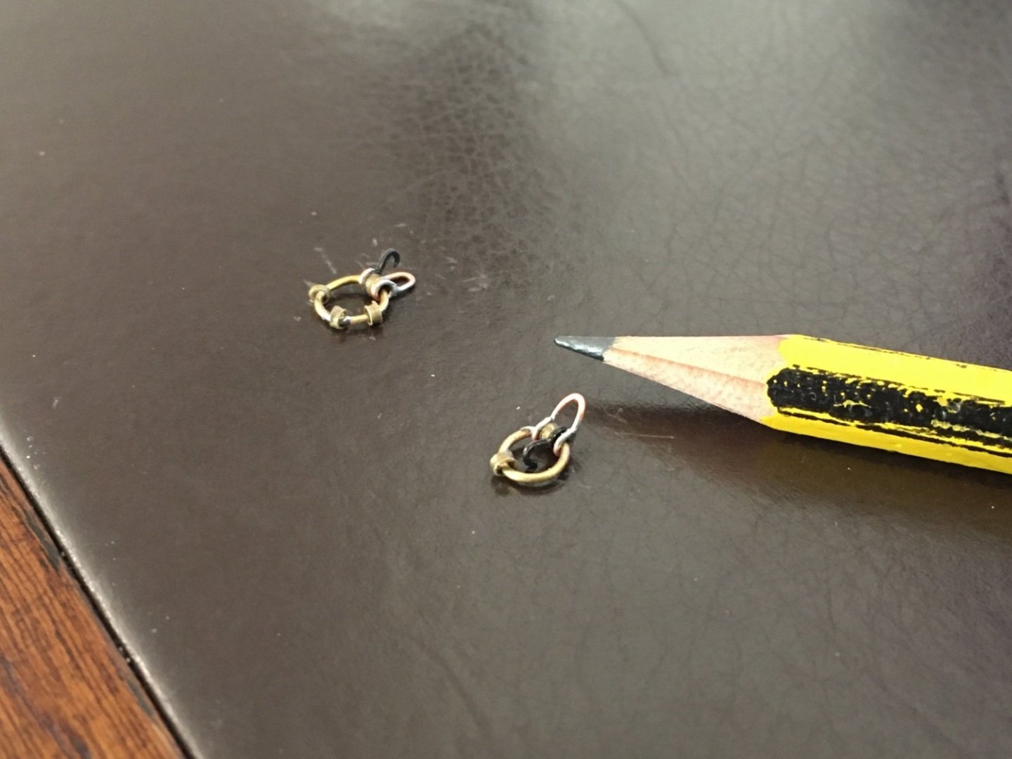
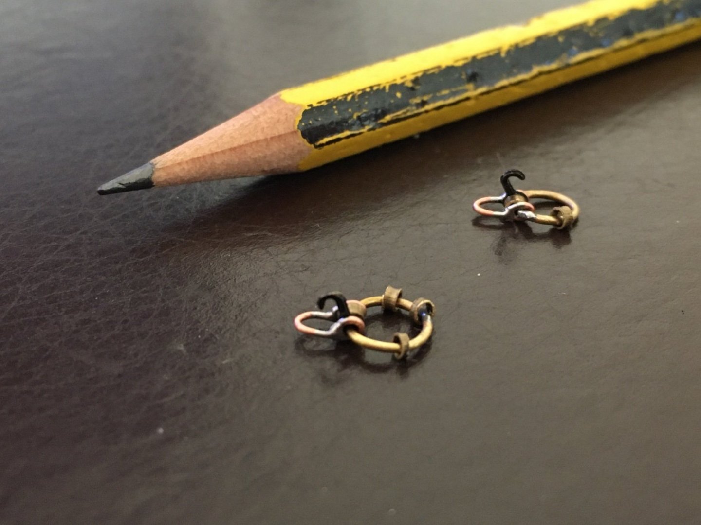
Graham and Ian thanks for your nice comments. Ian, to be honest I was quite confused how to go about rigging the bowsprit and its traveller. Going true some builds to find some details, in Bill's log I came acrossI the correspondence between you and Bill re the bowsprit rigging. With my Longridge, Bill's persistence to detail and your excellent hints I think now I have a good idea how to go about it. I seized all the ropes that go to the traveller before I fit it to the Jib as I think it would be much more difficult to seize them when it is in place. Hopefully I got it right and I will rig all the attached ropes to their respective place. According to my understanding from what I gathered from Longridge, Bill and Ian here is an image of my traveller withe ropes all marked which hopefully I will rig to their right place. Robert
- 527 replies
-
- 6
-
-
- caldercraft
- victory
- (and 1 more)
-
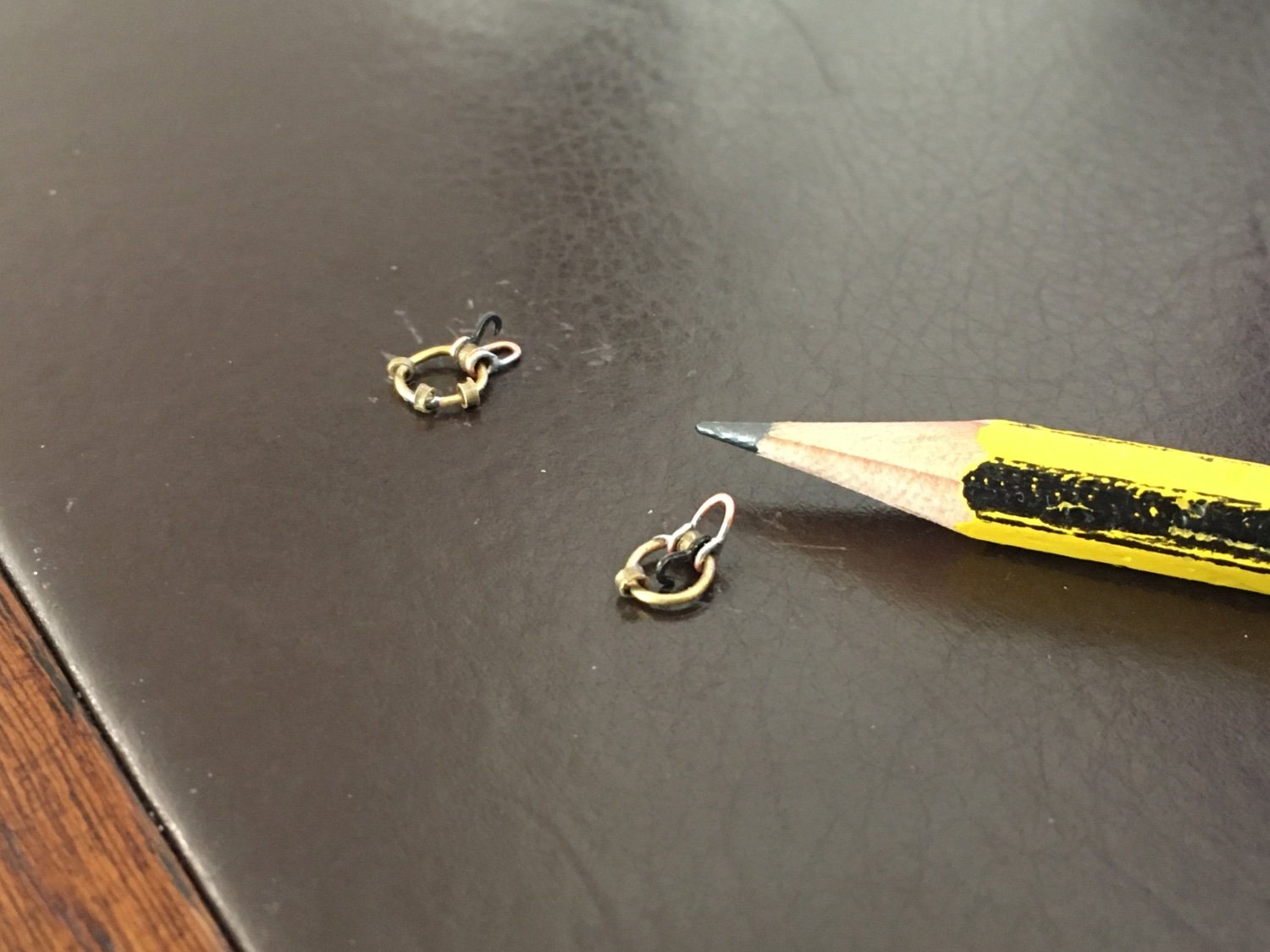
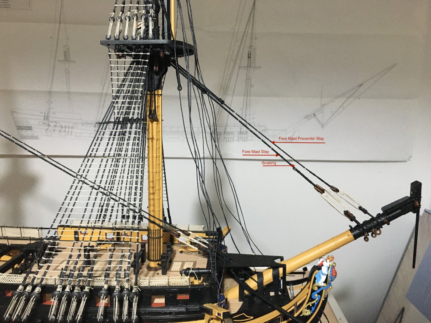
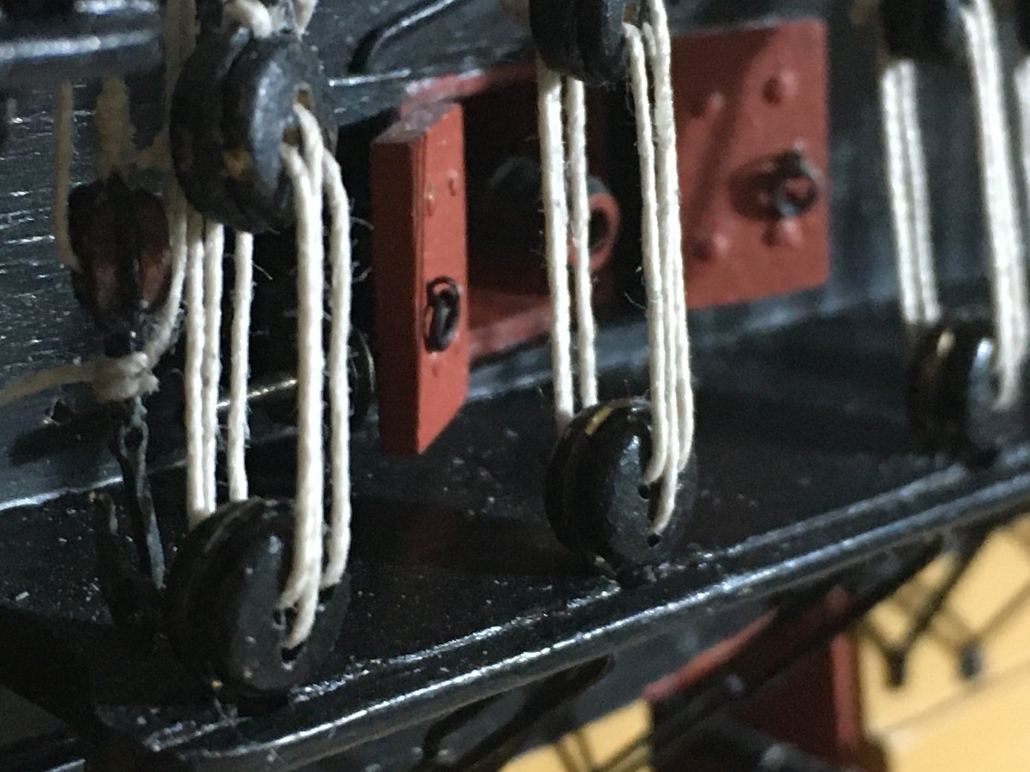
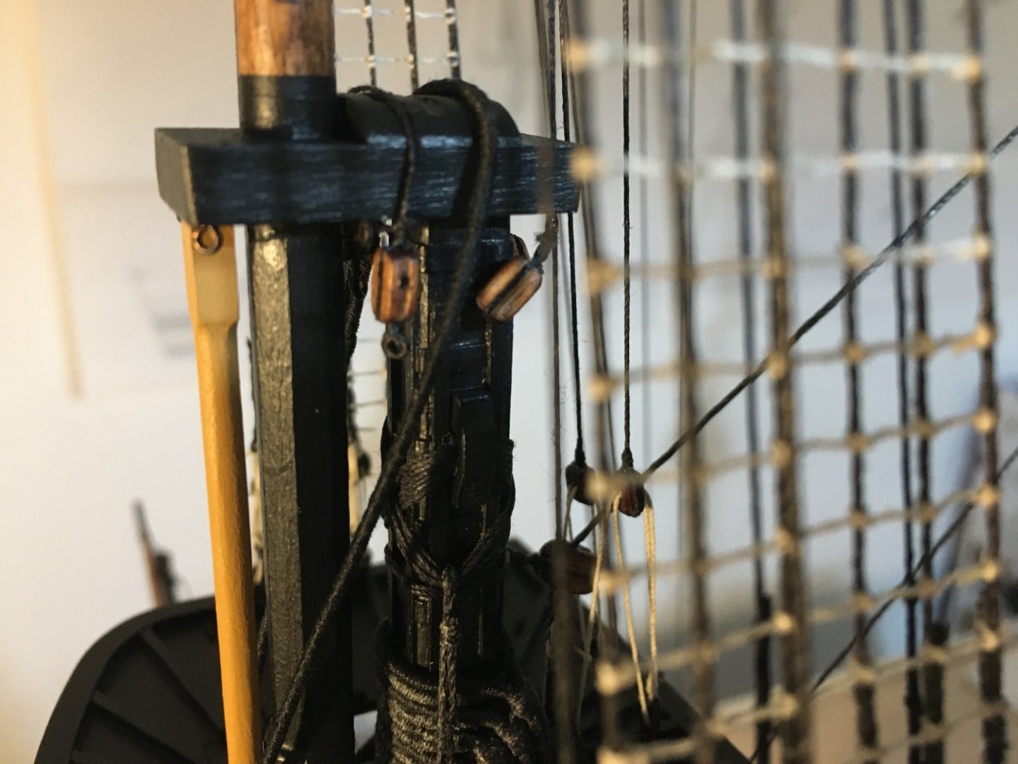
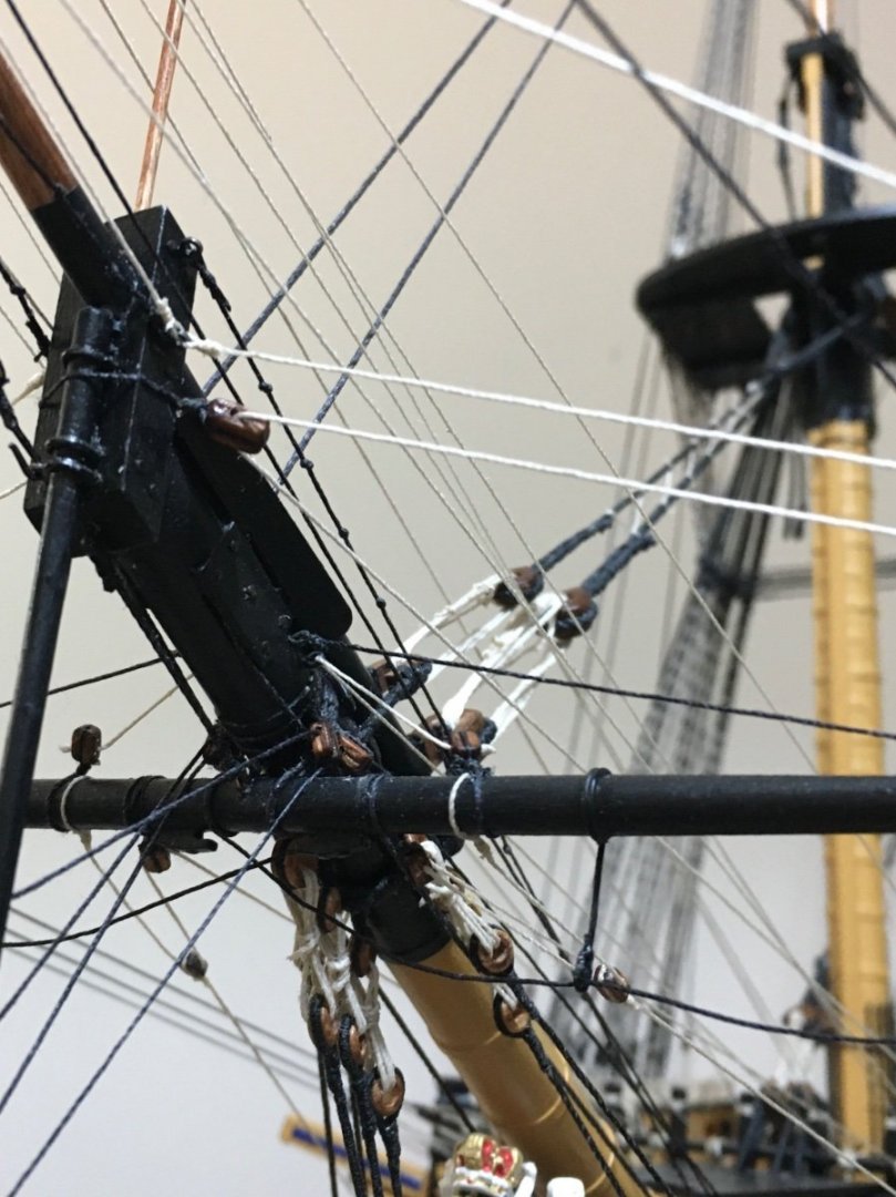
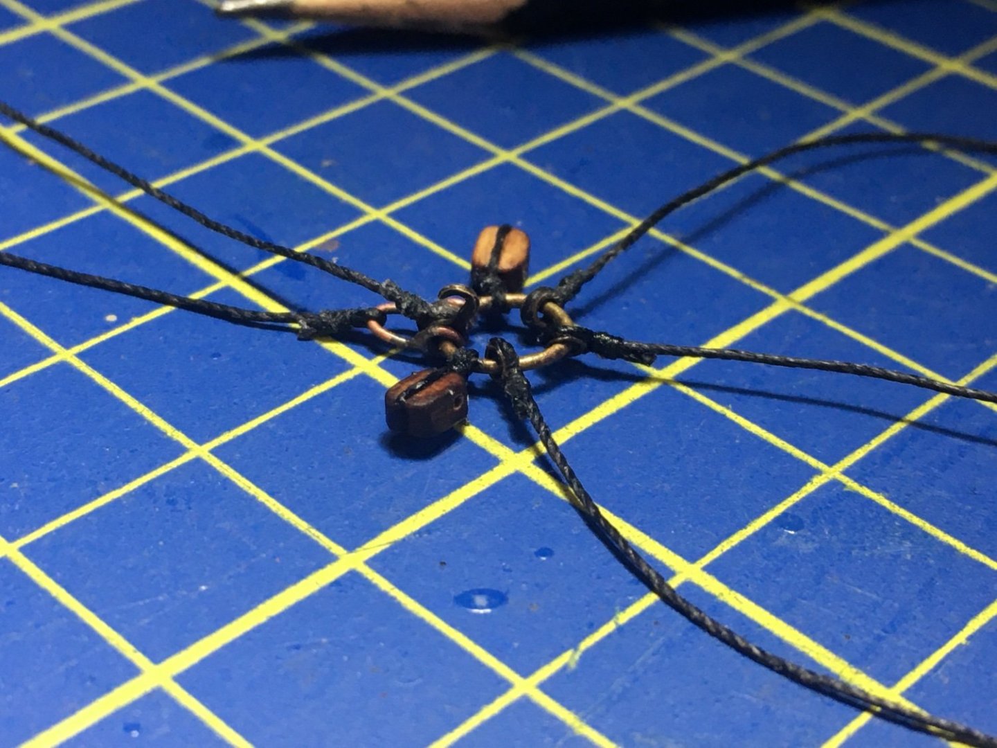
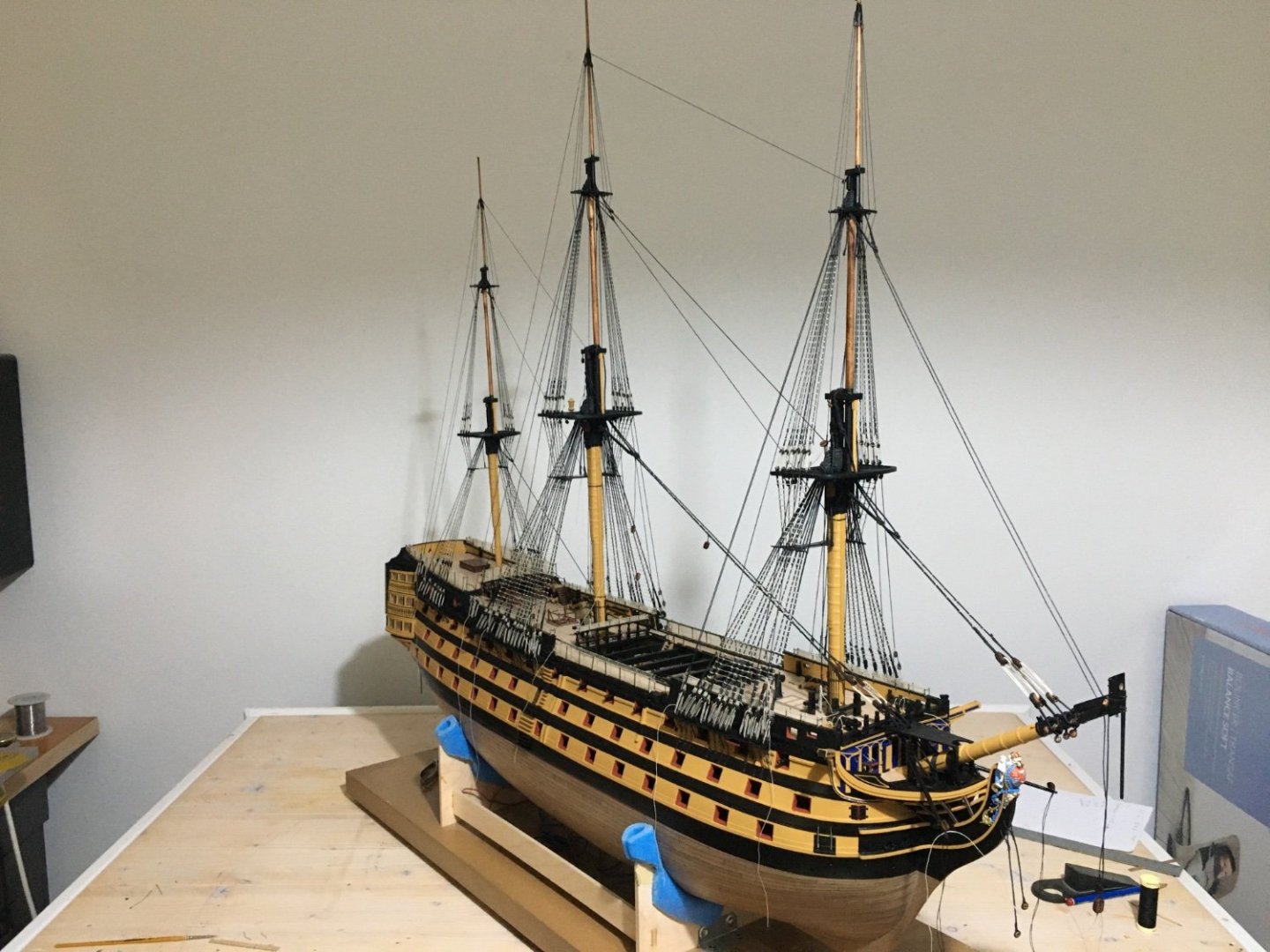
More work on the stays and backstays. The Fore Topmast Preventer Stay and the Fore Topmast Stay passing through the sheaves in the bee of the bowsprit and their respective blocks seized at the ends with the falls also seized into their ars. They are to be belayed to the knightheads. The Mizzen Topgallent Stay secured to a span around the main top trestletrees. The Main Topgallent Stay secured the same to a Span around the fore top trestletrees. They are not tensioned yet. Span with thimble for topgallant stays as shown in Longridge's book. When I came to the Jib Stays, the manual tells you the standing end is made fast at the end notch of the Jibboom. Looking into Longridge's book it is made fast to a 'traveller'. The manual has completely omitted this traveller. After studying the rigging that goes to this traveller, of which some in the manual is rigged to a different point on the Jibboom and the Flying Jibboom, I decided to include the two travellers. It was pretty confusing for me to find what goes where. So with a diagram from Longridge I had a go at the travellers. About the blocks, I am not sure yet if I will include them as I am thinking that on such a scale it might start to be too busy. Ring and shackle made up of brass rod, thimbles made up of brass tube and hook from extra small hooks supplied with the kit. Ends of ring and shackle soldered together. Robert


- 527 replies
-
- 4
-
-
-
- caldercraft
- victory
- (and 1 more)
-
Just came across your build log and visited some of your other builds. Really beautiful detailed work Olha. Videos very informative as well. Congratulations. Robert
-
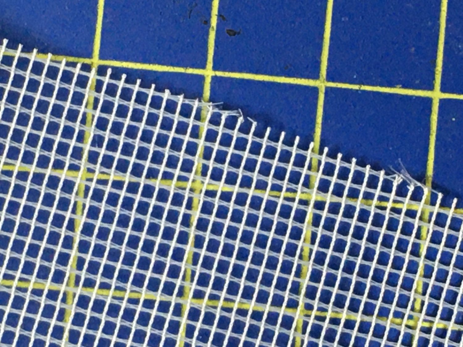
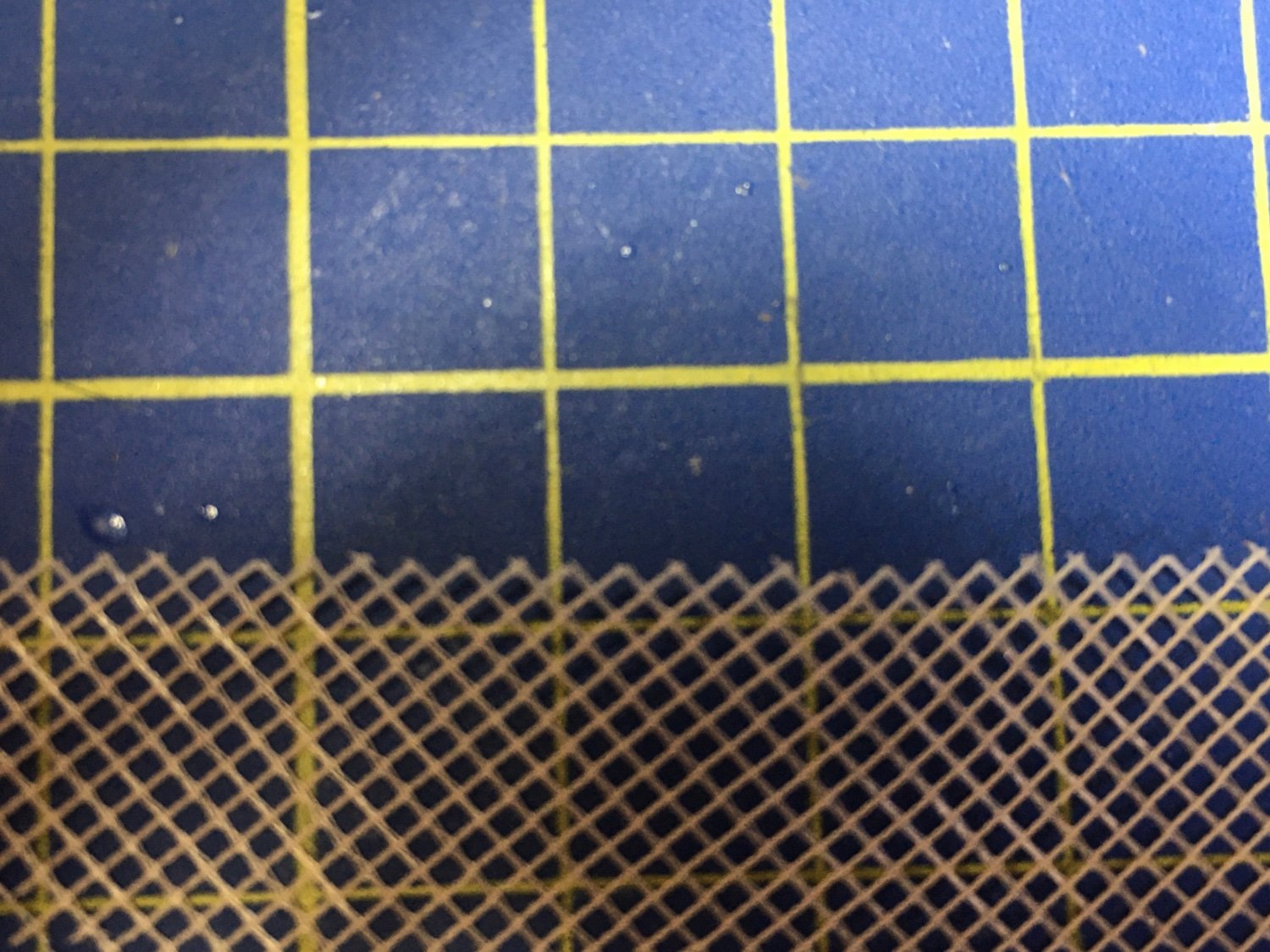
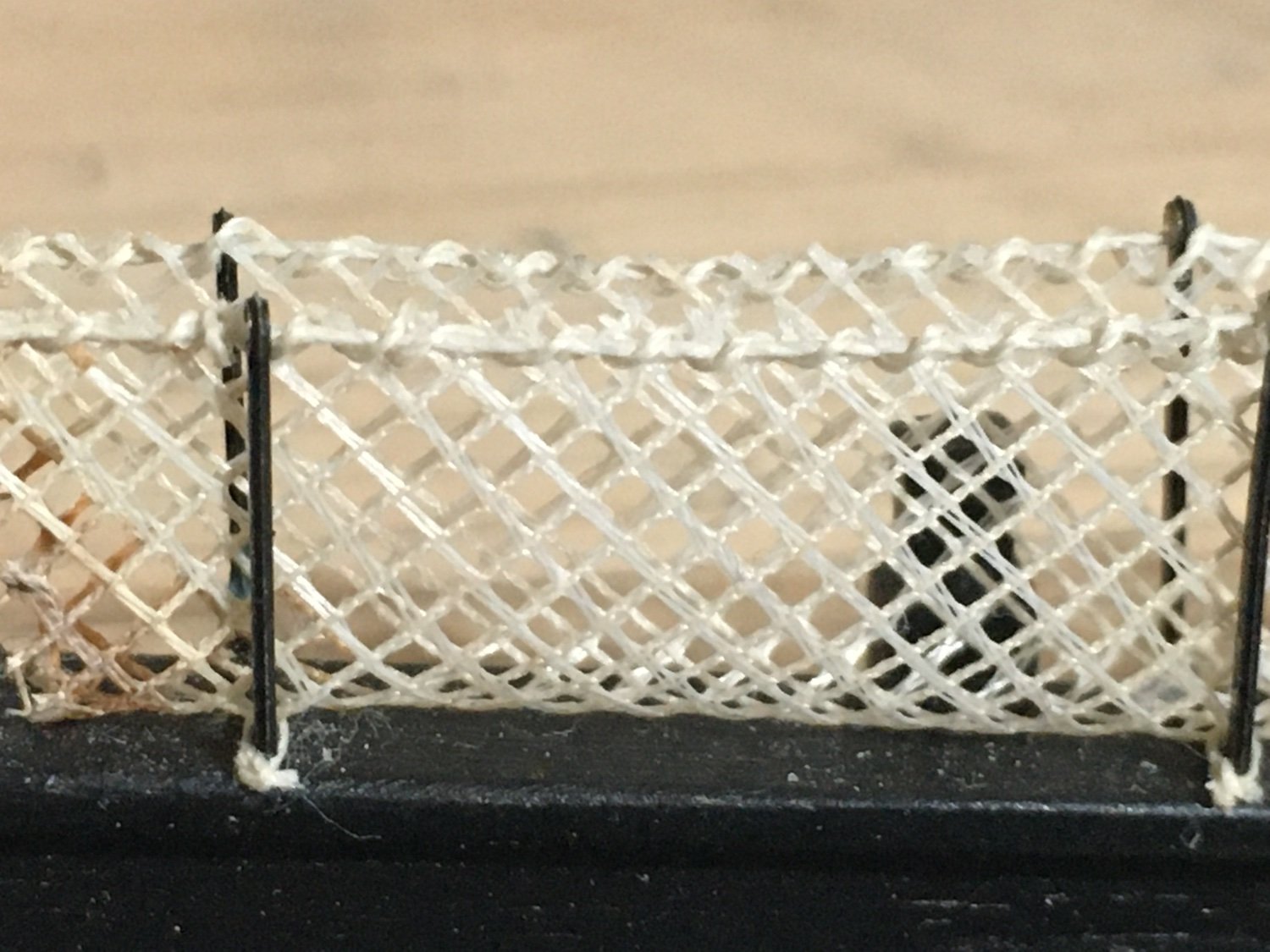
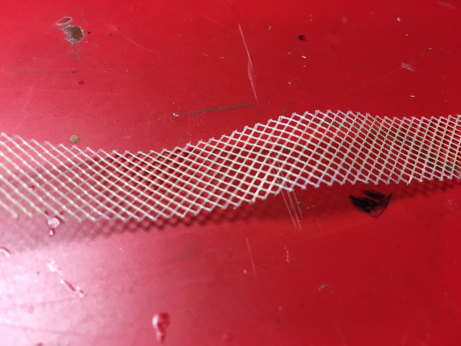
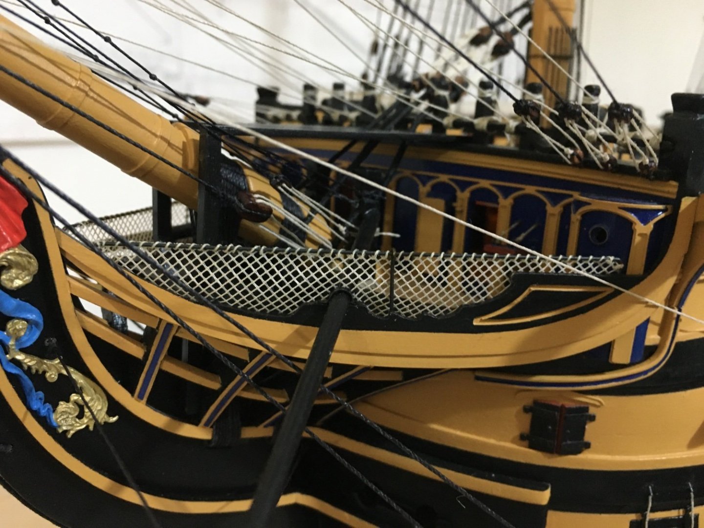
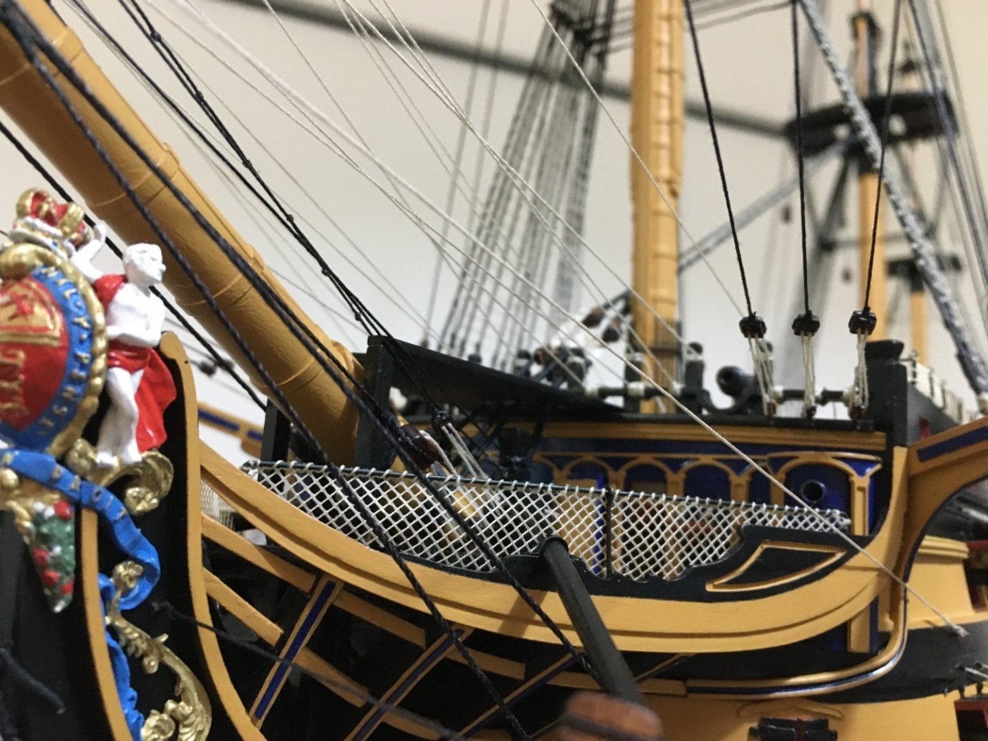
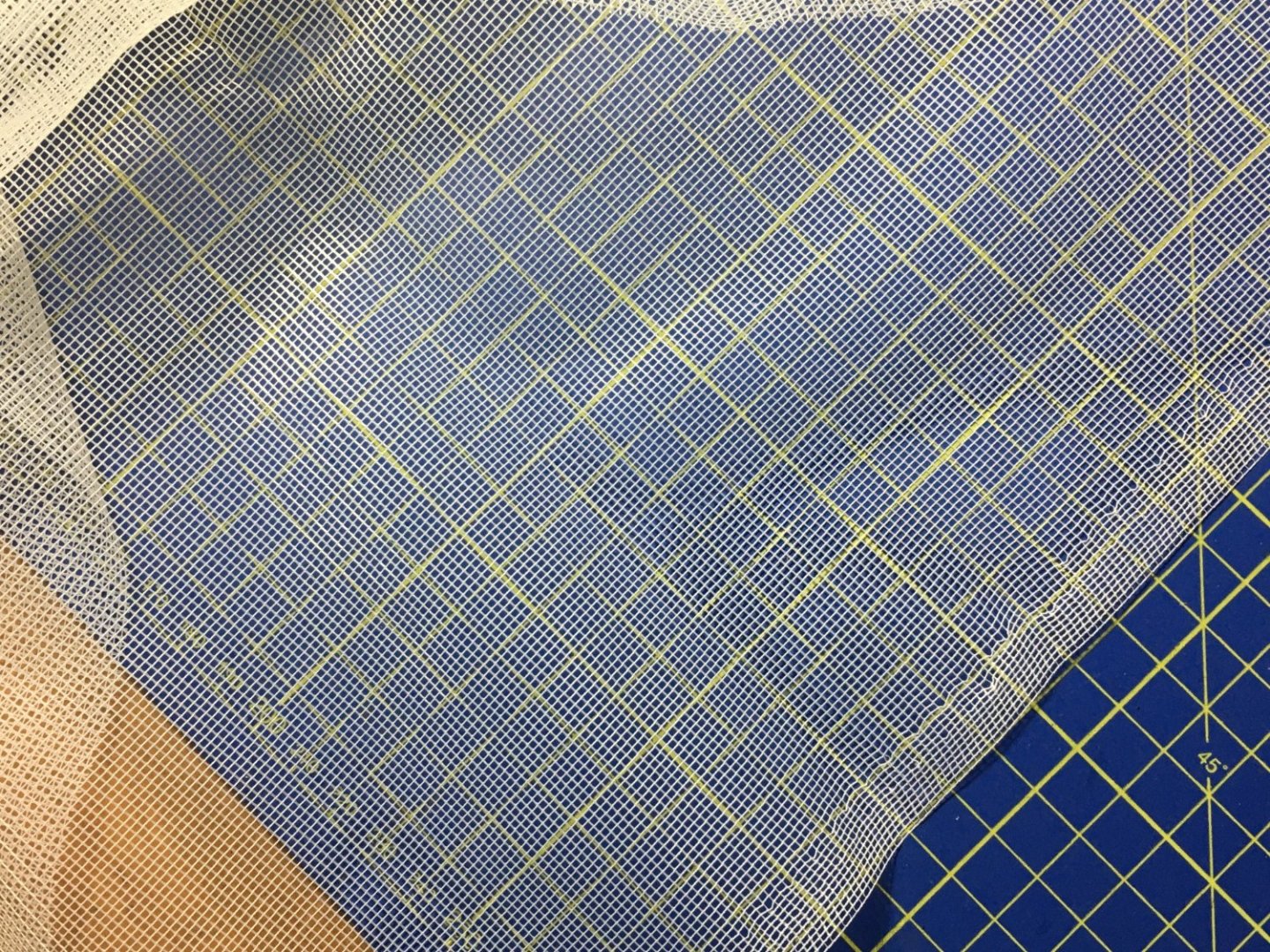
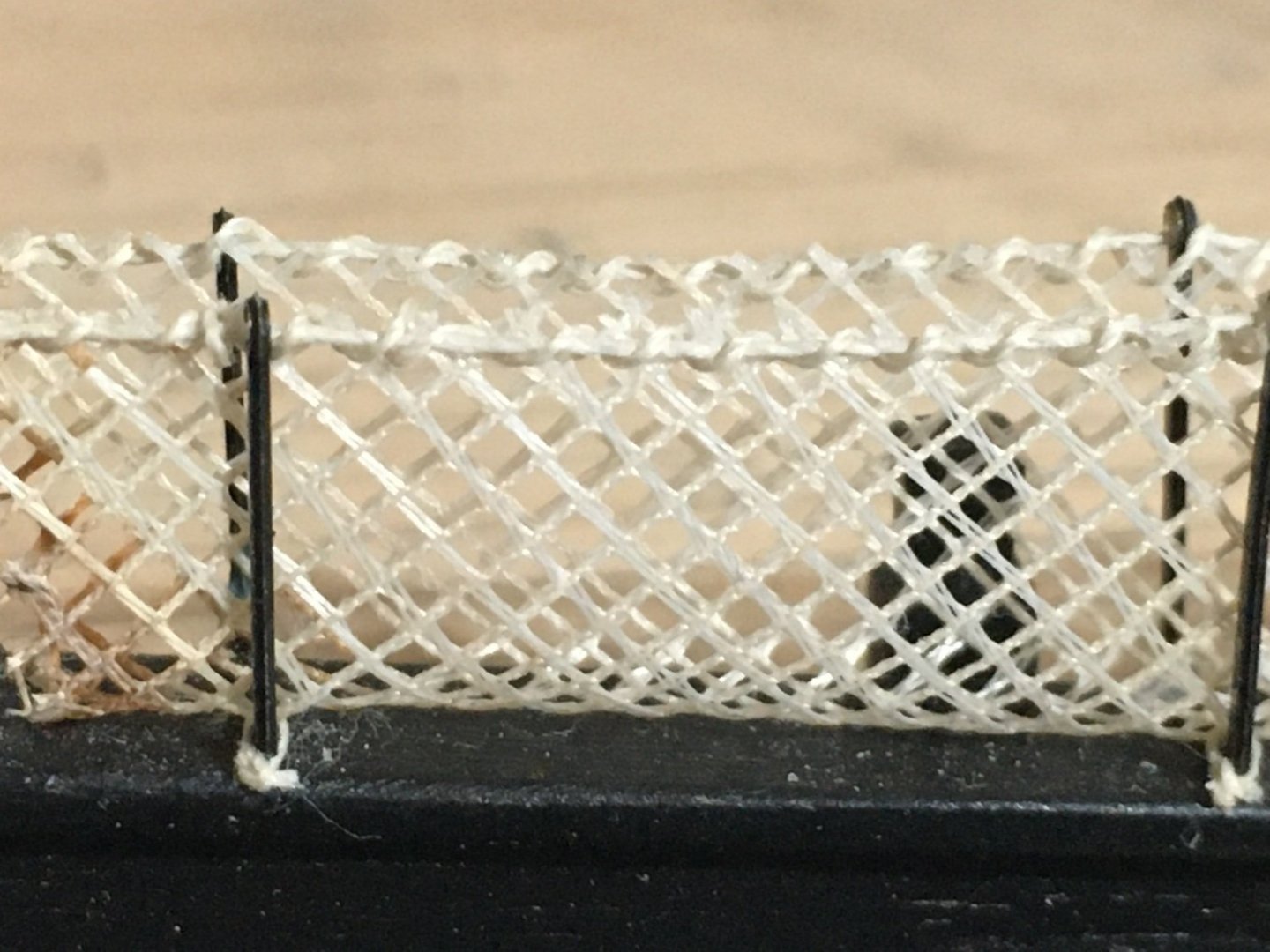
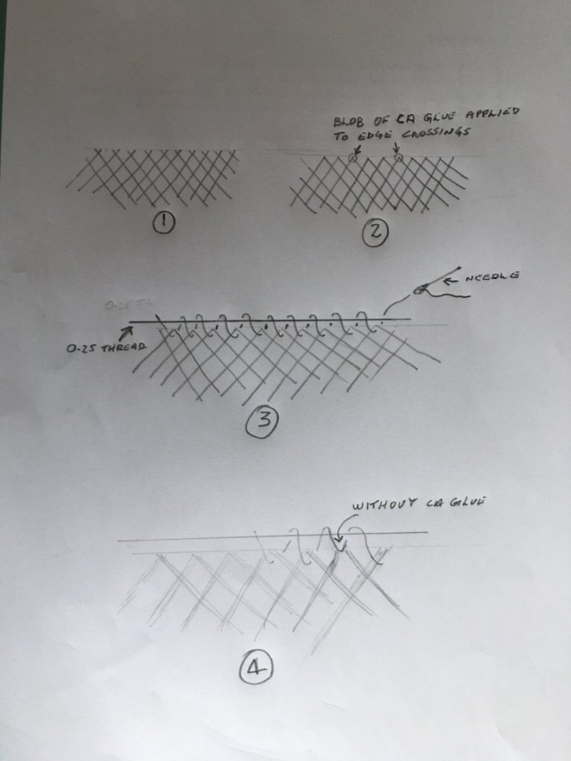
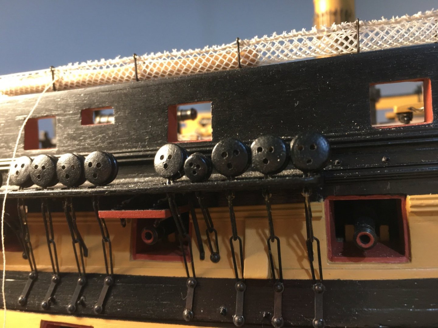
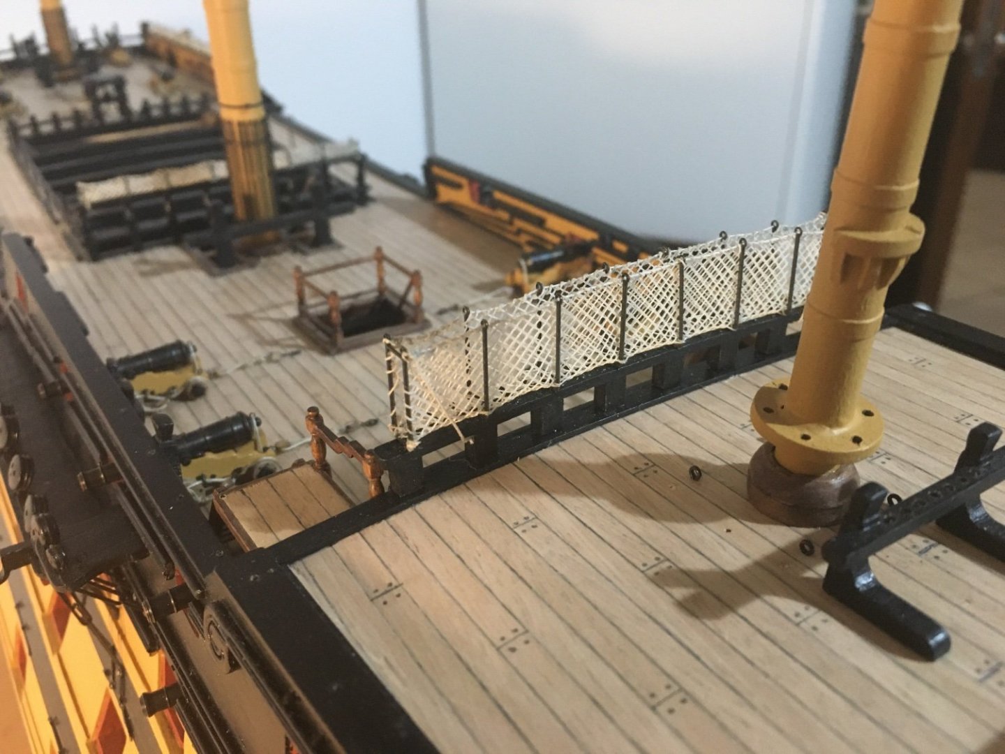
Hi Mike, thank you. As I had said earlier the netting took me quite a long time to find some acceptable material to look as realistic as possible. I tried using tulle but didn’t like it. I tried to find something from hobby suppliers on line with no luck. Then as a last resort I tried a local drapery shop and when I was on the verge of giving up I noticed this material. I think it is some sort of a material to be used as a mosquito net, not sure. It has 16 squares per inch. It was only available in white or very light cream (nearly white). I bought a meter of it and did some tests. Close up First thing I noticed was that it was to whitish. The material was polyester so it doesn’t really absorb much. I tried leaving a piece in a cup of tea, and it did darken a bit. I tried to measure the width I needed to go inside the cranes. The material is made up pf very fine threads intertwined with each other when crossing each other. So I trimmed the netting to the width required from just a bit above from where they crossed each other (sketch 1). With the fist try they did not look good, the edge of the net was protruding up over the crane railing. Doesn't look good. I tried another piece but this time cut the netting exactly from the point they cross each other, as in sketch 2. The problem was that when I started sewing the net in place with the thread (railing) across the hammock cranes, edge started to open apart from where they crossed each other as shown in sketch 4. I tried another piece trimmed exactly where they cross each other and dabbed each edge crossing with CA glue. This kept them from coming apart. The manual tells you to use 0.1mm thread loped from one Hammock crane to the other, but I used the 0.25mm thread so that it will hide a bit more the edge of the net. To sew the net to the railing I used the normal Gutermann sewing thread (cream colour). With a needle I went through every edge crossing as shown in sketch 4. I tied the net to the crane bottom corners with a piece of thread to keep it in place. When finished I applied a coat of water down PVA glue all along the railing thread and the sewing thread. To keep it in place. End result. It is not as white as it looks in the photo. I can’t say I found it easy, it was quite tedious and did a few tries before getting them to my satisfaction. Even getting the net the right width was tricky. There were instances where it was too wide and I had to remove again, trim and glue edge crossings again and sew in place again, or the opposite too narrow and had to make a new net again just a bit wider. I think the extra effort was worth it as its a pity to have so much work on the model and then have the nets look so unrealistic. Hope this is of help. Unfortunately I cannot Indicate a brand or anything for the net as I bought it from a drapery store that sells by the meter the store doesn’t do online selling. Robert


- 527 replies
-
- 7
-
-
-
- caldercraft
- victory
- (and 1 more)
-
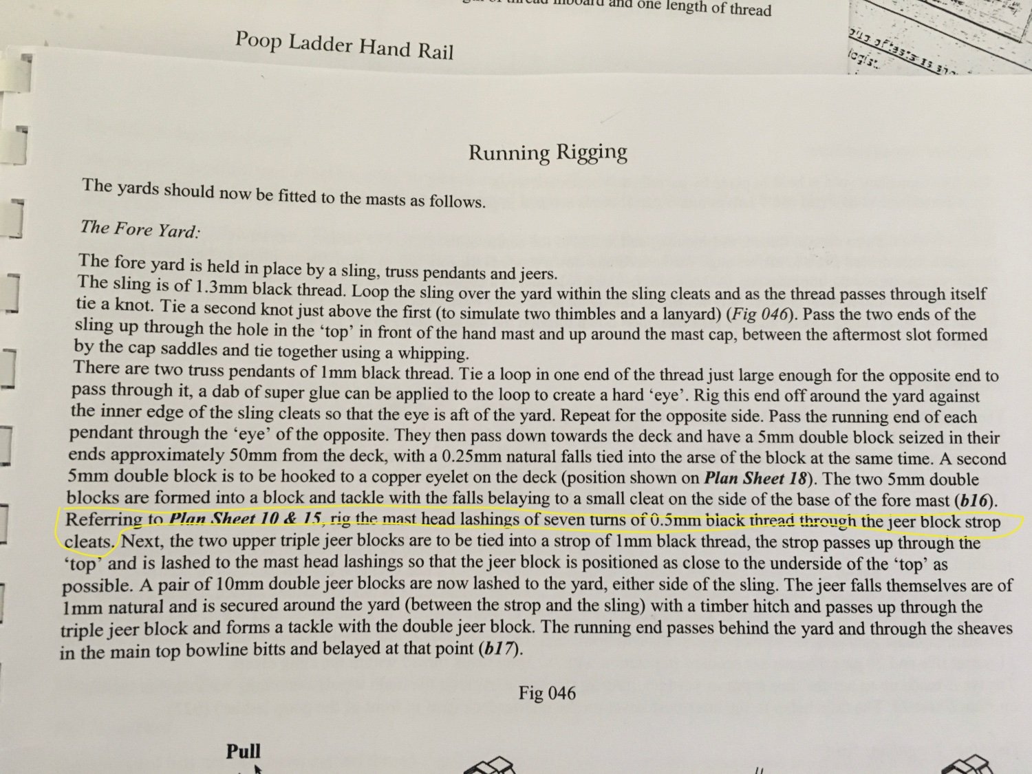
Hi Mort, I am assuming you meant the 10mm Jeer Blocks. I used 1mm thread. The Mast Head Lashings are made up of seven turns of 0.5mm black thread. Regards Robert

- 527 replies
-
- 2
-
-
- caldercraft
- victory
- (and 1 more)
-
Excellent work Graham. Robert
-
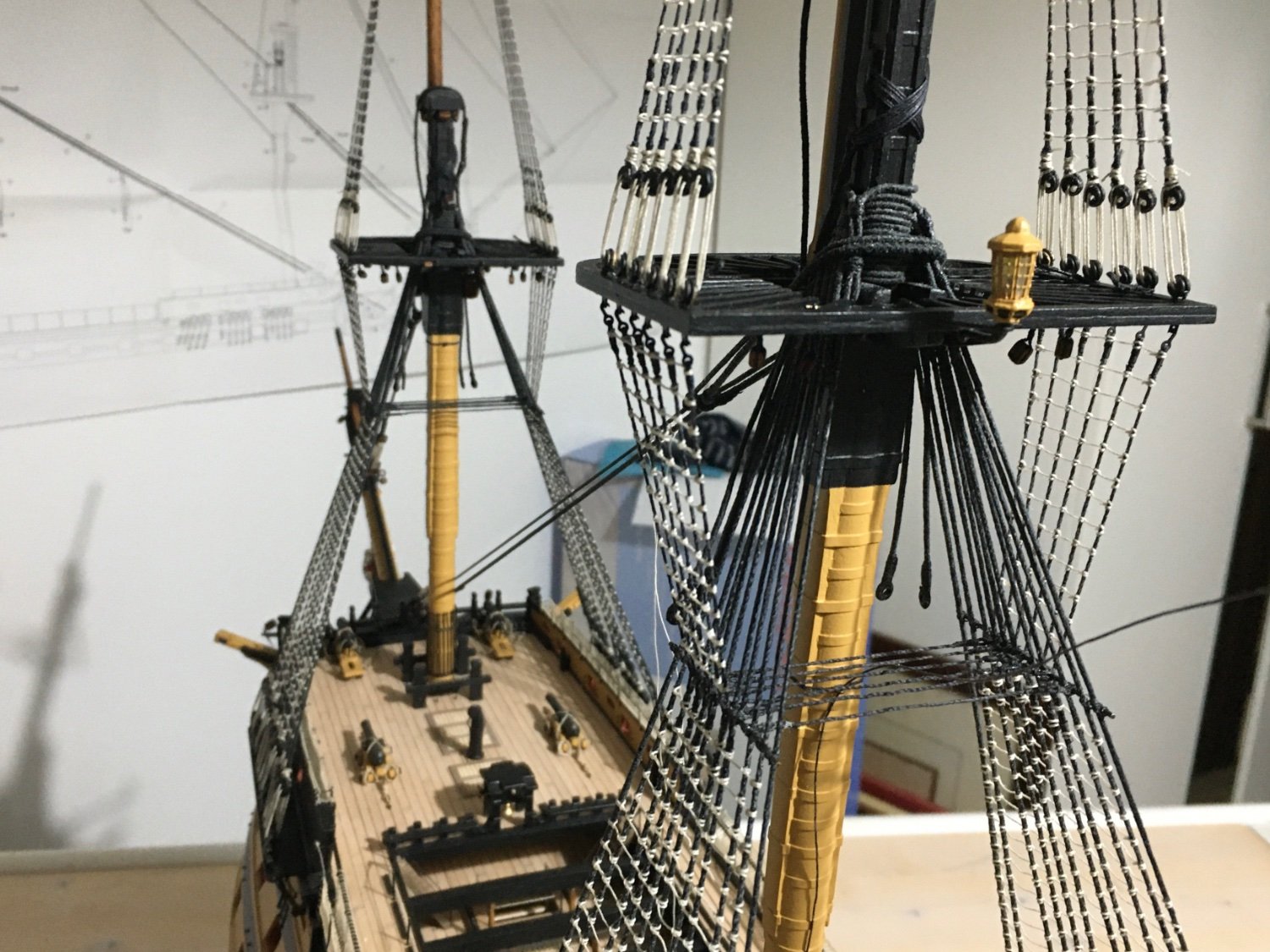
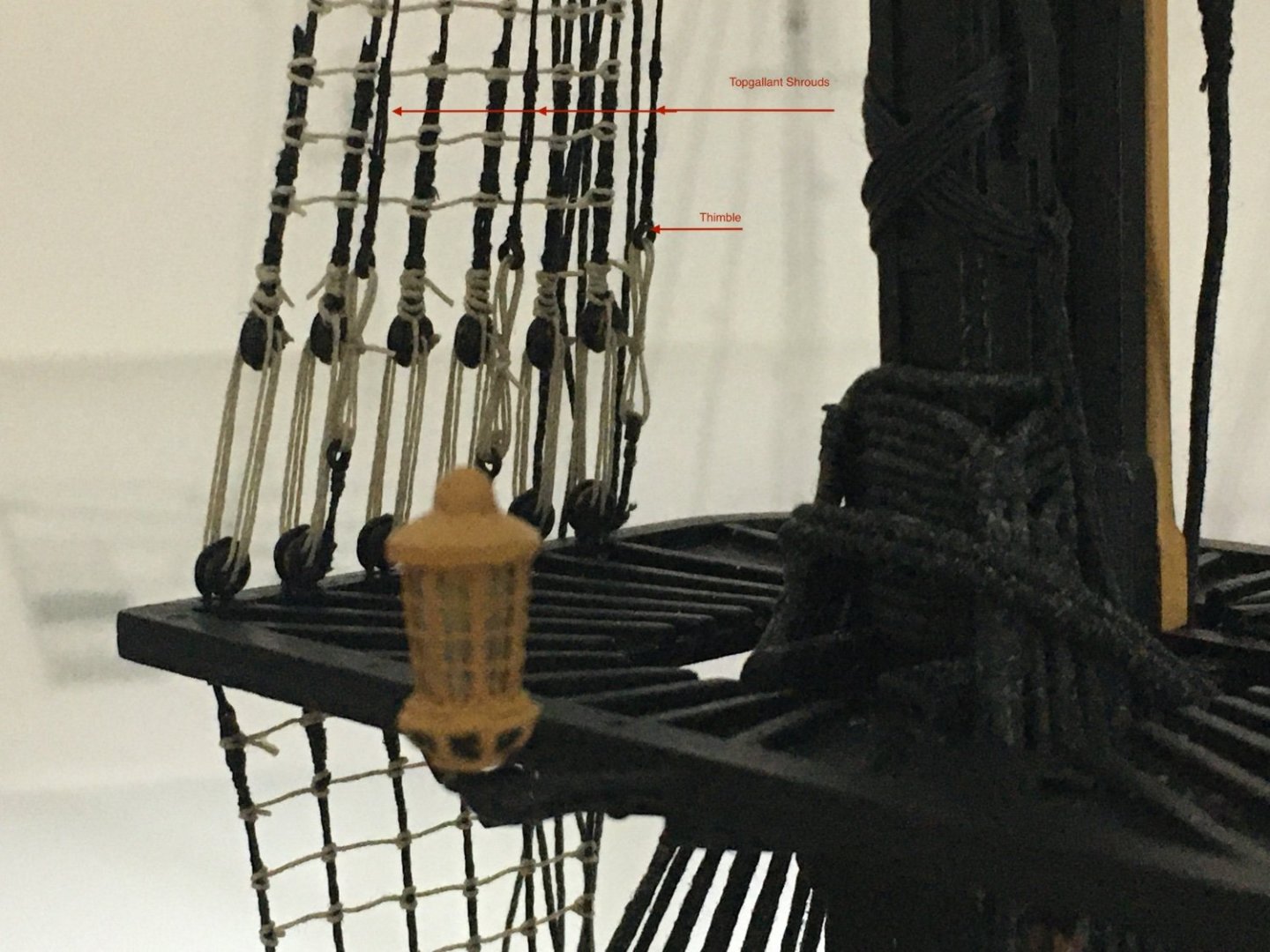
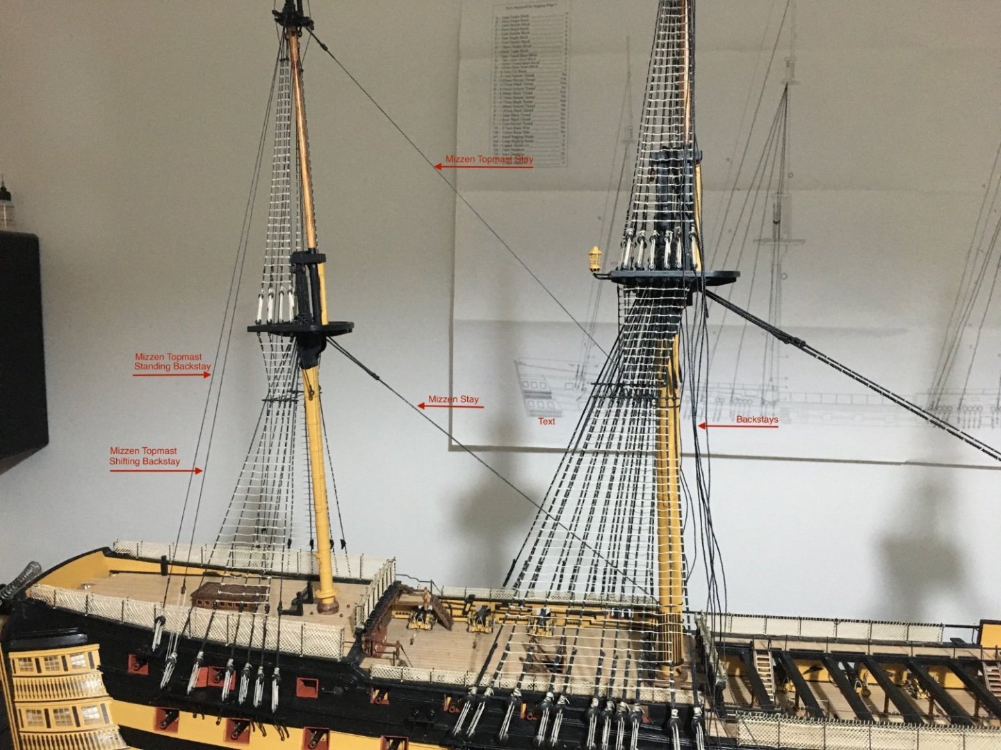
Thank you for the likes. I finished the snaking on the main stays and the preventer stays. I used a separate individual piece of thread to tie every point the snaking thread meets the stays. I also completed the Topgallant Shrouds and attached all the backstays to the masts. The Topgallant shrouds were passed from behind the staves and rigged as shown in photo. After the topgallant shrouds I continued the work on the Mizen backstays. The Standing backstay is very straightforward, it is attached to the channel with deadeye. The Mizzen Topmast Shifting Backstay requires a tackle. Hook seized with 3mm since block and falls seized into the ****. A 3mm double block is seized into the lower end of the backstay. Mizzen Topmast Backstays rigged in place and the Mizzen Stay and the Mizzen Topmast Stay also rigged in place. Image shows where the tackle is hooked to the eyelet on the channel which was prepared far back. Next step is the rigging of the backstays on the main mast. Robert


- 527 replies
-
- 8
-
-
-
- caldercraft
- victory
- (and 1 more)
-
Nice clean work Graham. Going forward, the work on the bow structure entails a lot of work. There is a lot of bending, twisting and dry fitting especially the rails. Take your time doing it as in my opinion, when finished, it is one of the most eye catching and beautiful parts of the ship. I am sure that with your skill you can do a beautiful job of it. Cheers Robert
-
A small update. Stays and Preventer Stays for the lower masts in place. For theFore and Main stays I used the rope I ordered which found very good. The loop for the Topmast and Topgallant stays has to go round the mast over the loops for the backstays. So basically the topmast and topgallant stays cannot be fitted before the backstays are in place. I started the snaking on the main stay and preventer stay but I did not like how they looked. I tried the marlin hitch knot as indicated in the manual, but somehow the knotdid not look right. Hope I was doing the right way. I will try a different way. I will start working on the backstays so I will be able to continue with the stays. Robert

- 527 replies
-
- 7
-
-
- caldercraft
- victory
- (and 1 more)
-
Hi Nigel, sorry for the very late reply, but the last couple of weeks have not been so good for me, unfortunately one of my brothers has been diagnosed with serious health problems and I was'nt opening the forum. To cut the walnut I didn't find it really necessary to wet it, if it's very thin I use a blade and if its ticker I use a small hand saw with very fine teeth with a mitre box. I have two of them, one with 24 tpi and another 42 tpi. But for bending I find it a must to wet the walnut. I wet it, use an electric heat bender and sometimes keep wetting it during the process. In the meantime I have received the rope for the stays and carried some work on them. I will soon upload a post with the progress. Ronert
- 527 replies
-
- 2
-
-
- caldercraft
- victory
- (and 1 more)