HOLIDAY DONATION DRIVE - SUPPORT MSW - DO YOUR PART TO KEEP THIS GREAT FORUM GOING! (Only 24 donations so far out of 49,000 members - C'mon guys!)
×

Robert29
-
Posts
417 -
Joined
-
Last visited
Content Type
Profiles
Forums
Gallery
Events
Everything posted by Robert29
-
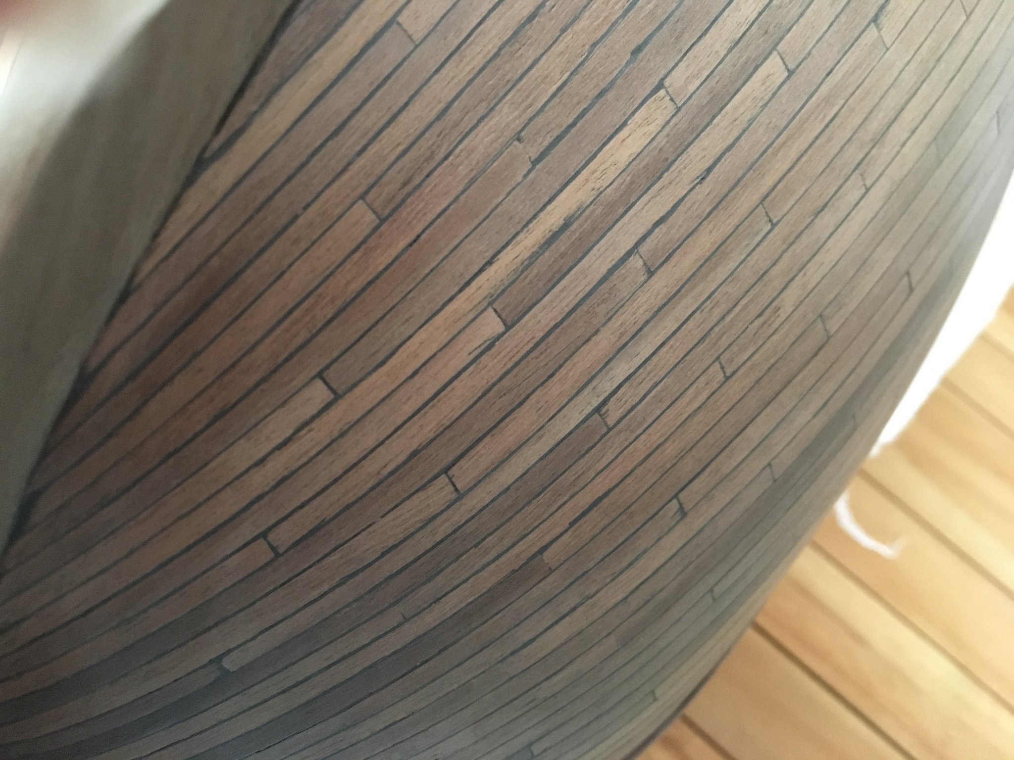
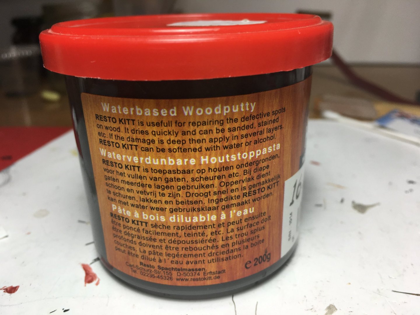
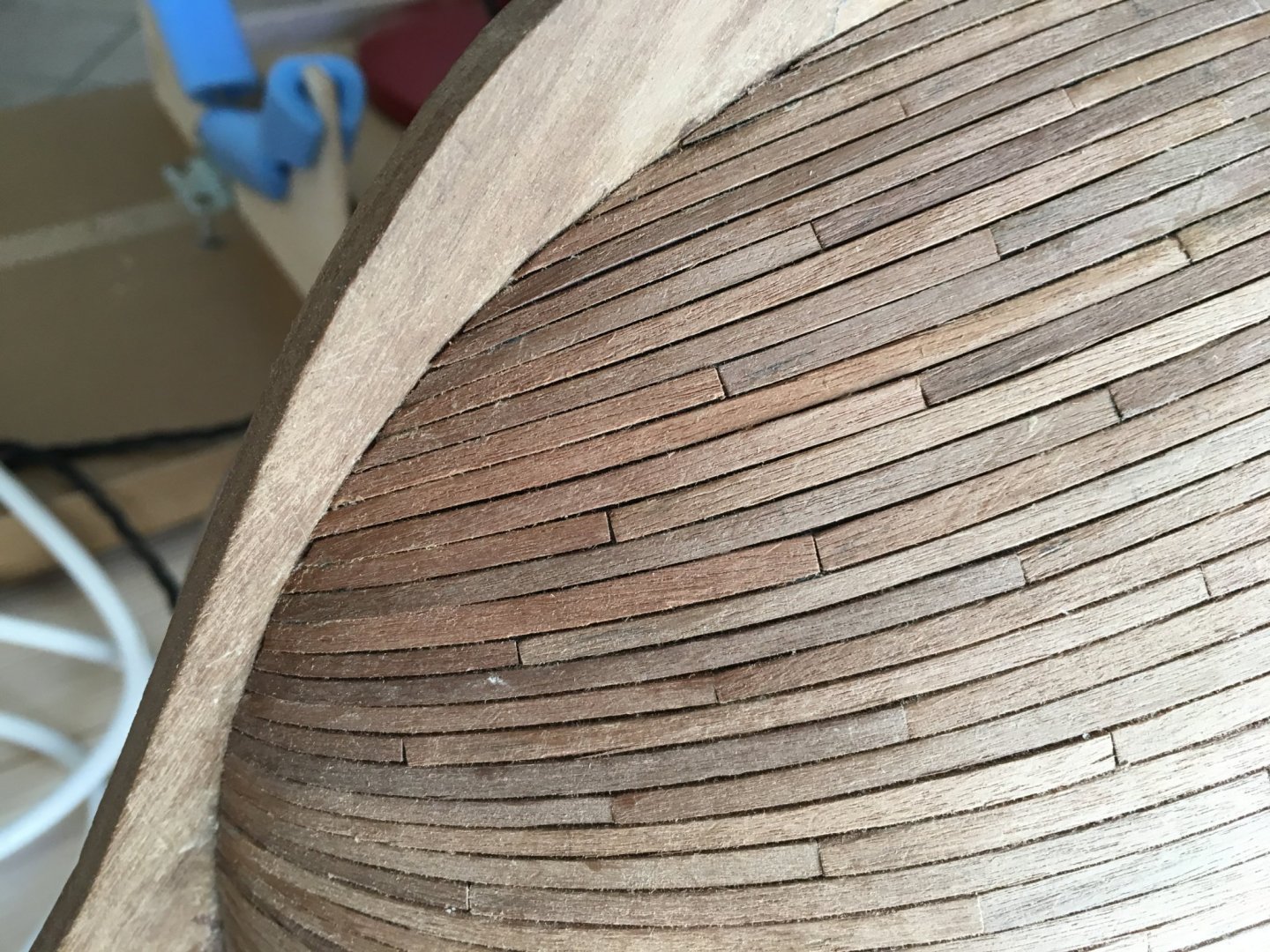
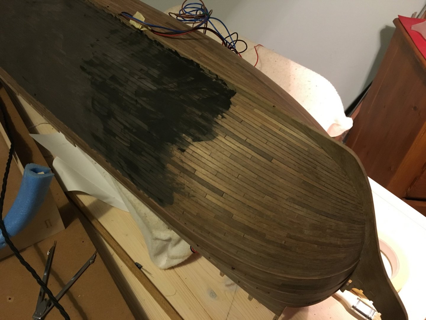
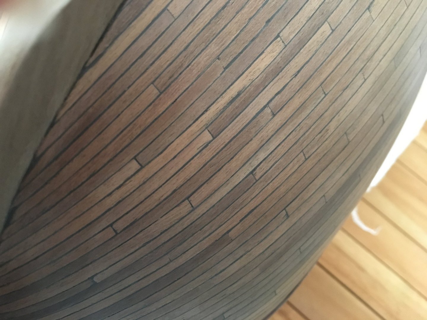
 Thank you Graham, much appreciated. The fire buckets you made for your Victory look great. Jeff, thank you for your nice comment. I used normal water based wood filler which I had bought from a local ironmonger. The important thing is that when it dries it will still be easily sanded as otherwise, if it's too hard it will be difficult to remove the excessive filler to uncover the plank grains again. Probably you can get it, or something similar, from most ironmongers. I have attached a few images you might find of help. Before applying the filler. - I left a small gap between the planks for the filler. Applying the filler. - I pasted the hull allover and rubbed it in all the grooves. When it dries it becomes a bit light sort of greyish, but once you apply the varnish over it, it will get darker again. After sanding and varnishing. - All the excessive filler sanded away and varnished. I would suggest that you plank a small piece of wood and carry the whole process on it and see the final result. That way you would know you have the right filler which will give you the result you are looking for after varnishing. Avoid experimenting on the hull itself as you might not get the resuly you want and could be difficult to reverse the process. As for the paints I am using the acrylic Admiralty paints which I had bought from Cornwall Model Boats. Hope this is of help to you and good luck on your build. Robert
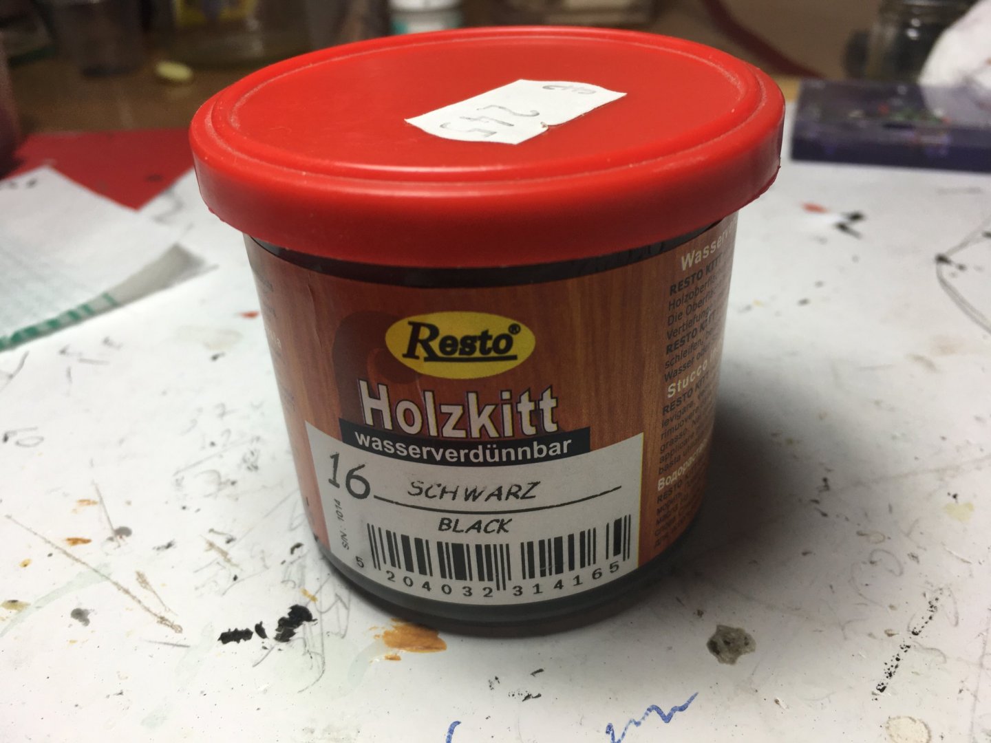
- 527 replies
-
- 8
-

-
- caldercraft
- victory
- (and 1 more)
-
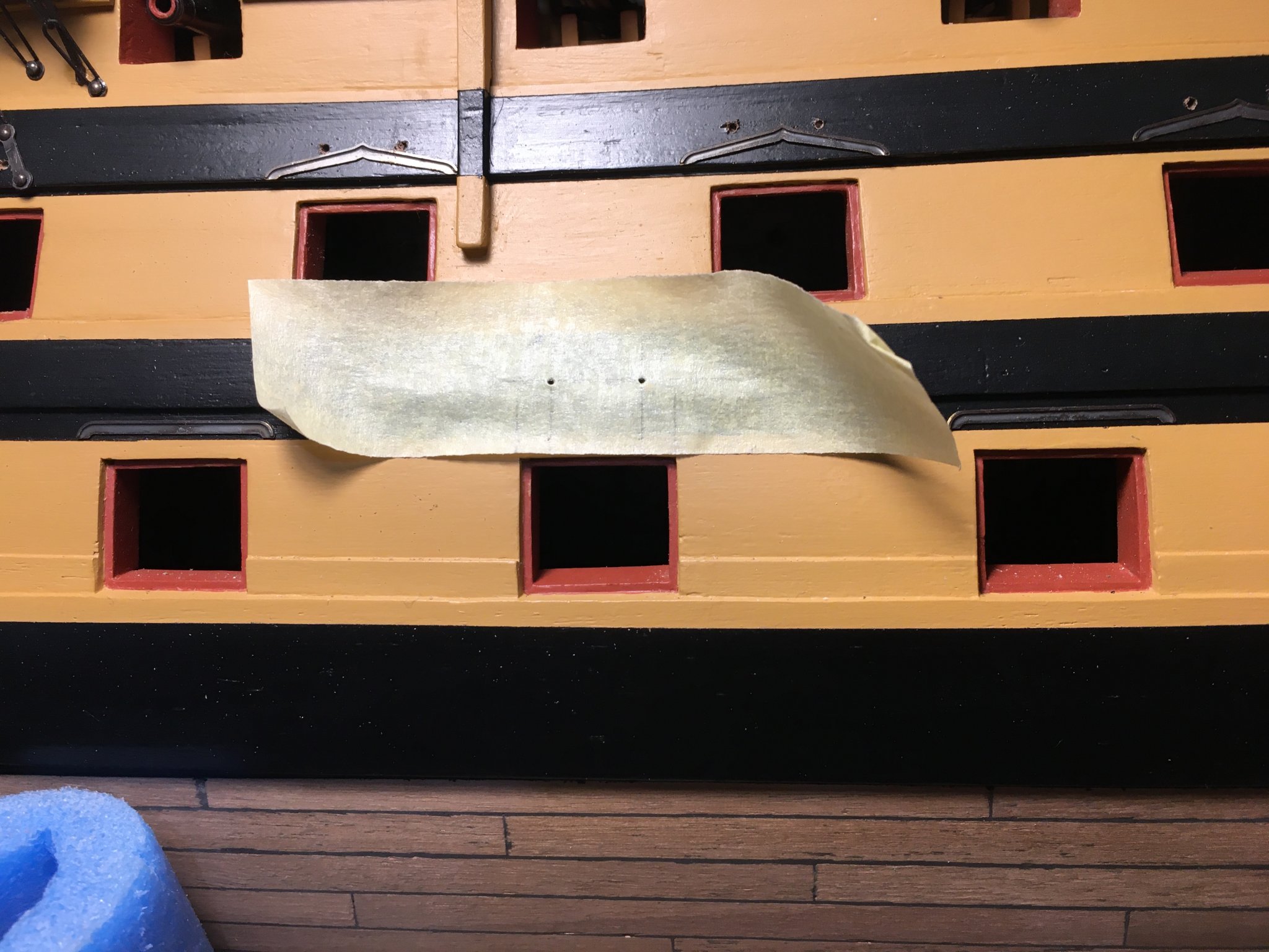
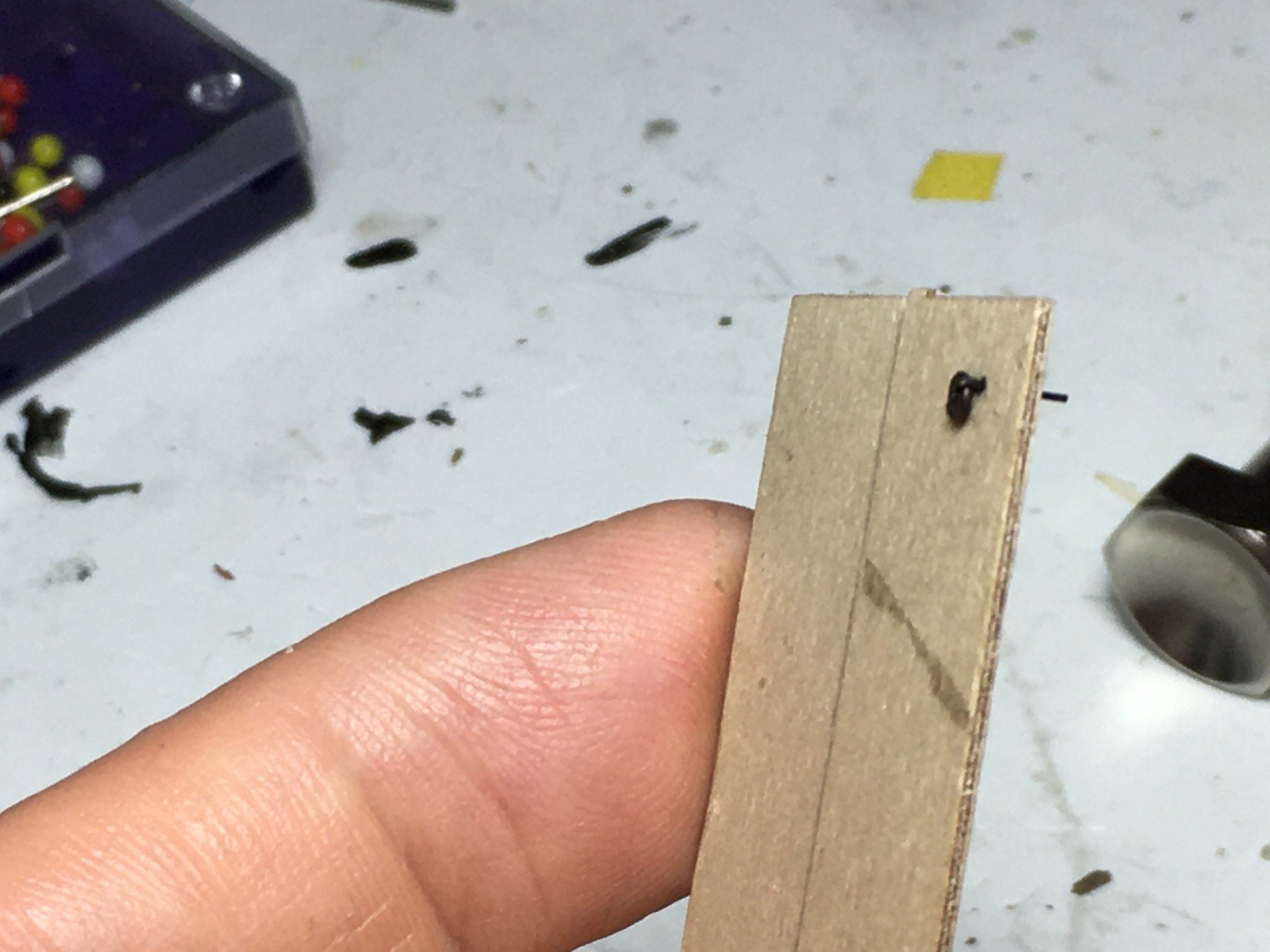
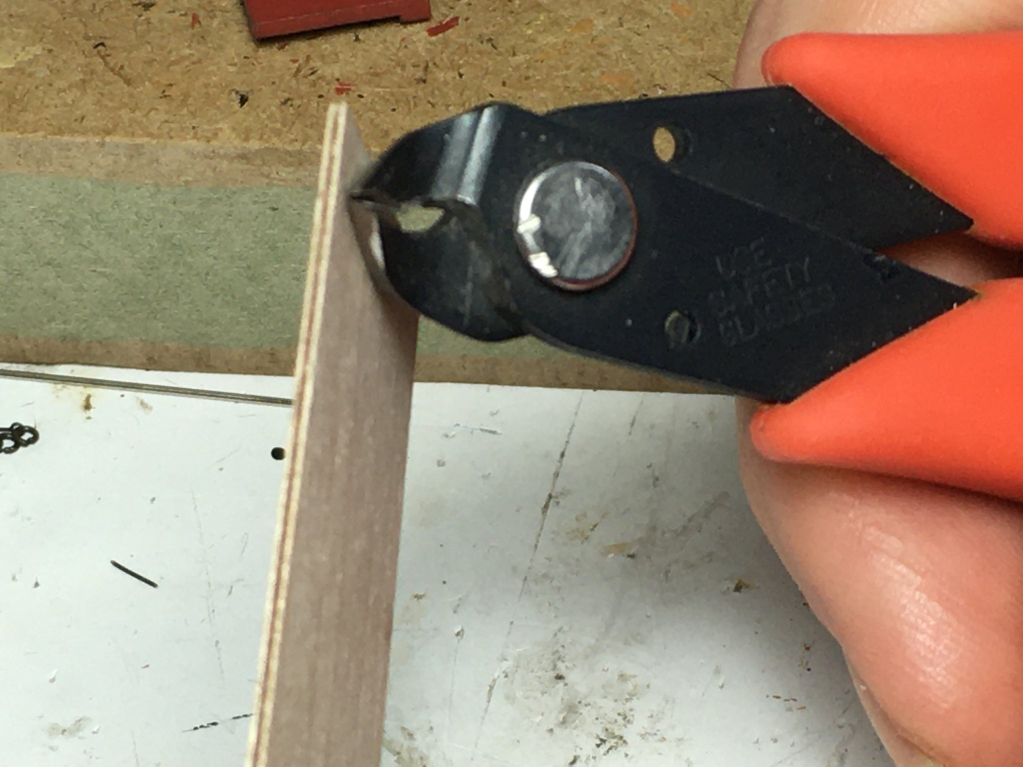
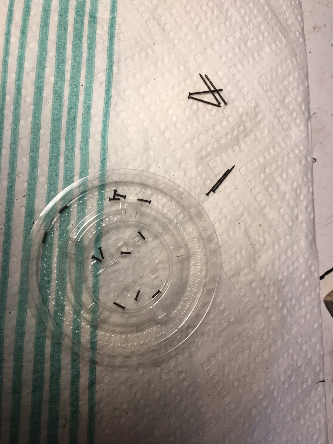
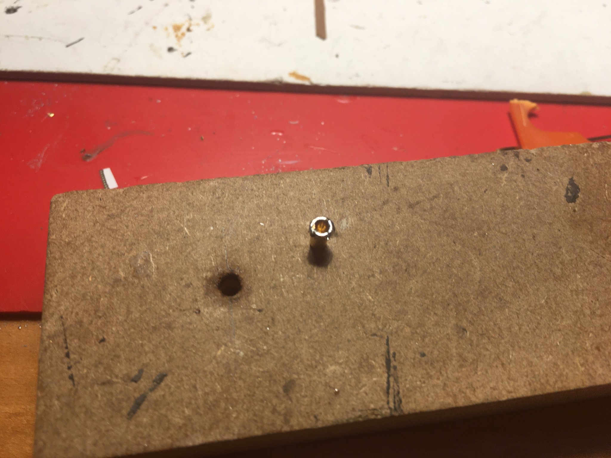
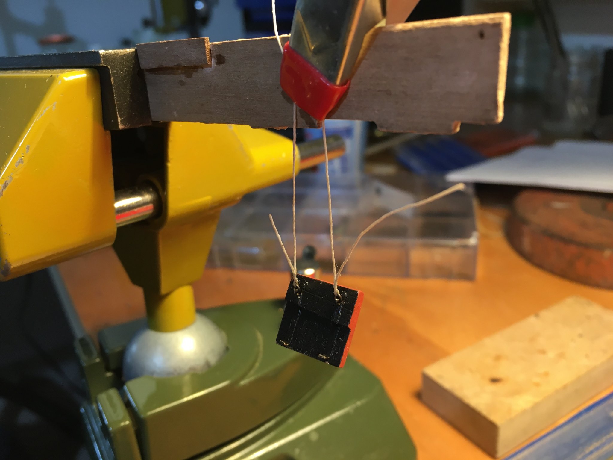
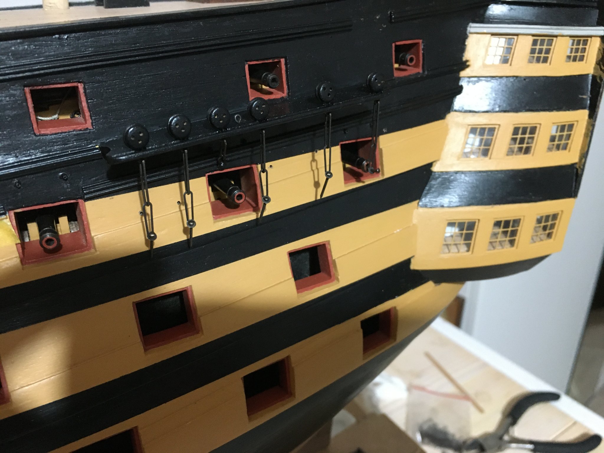
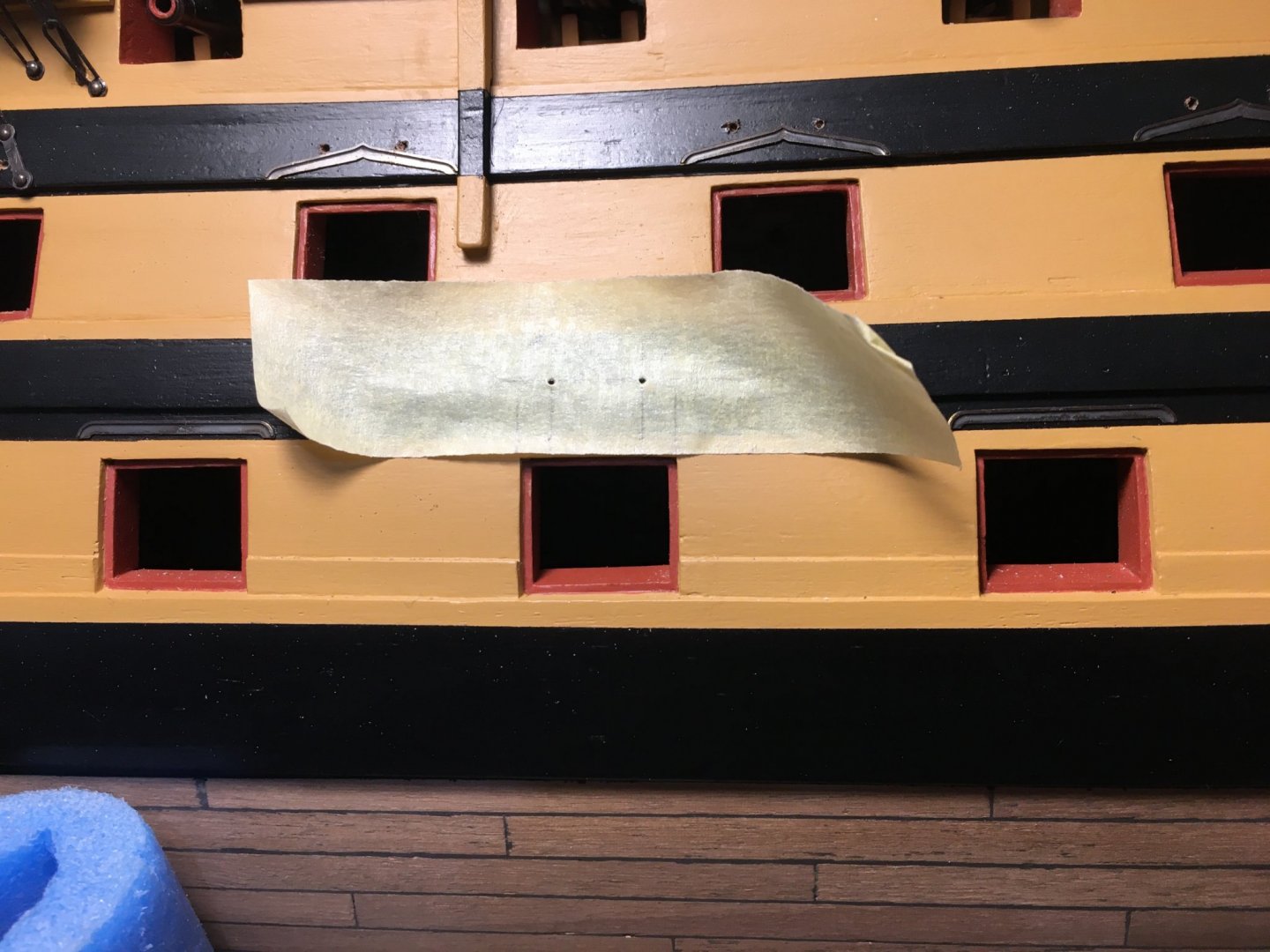
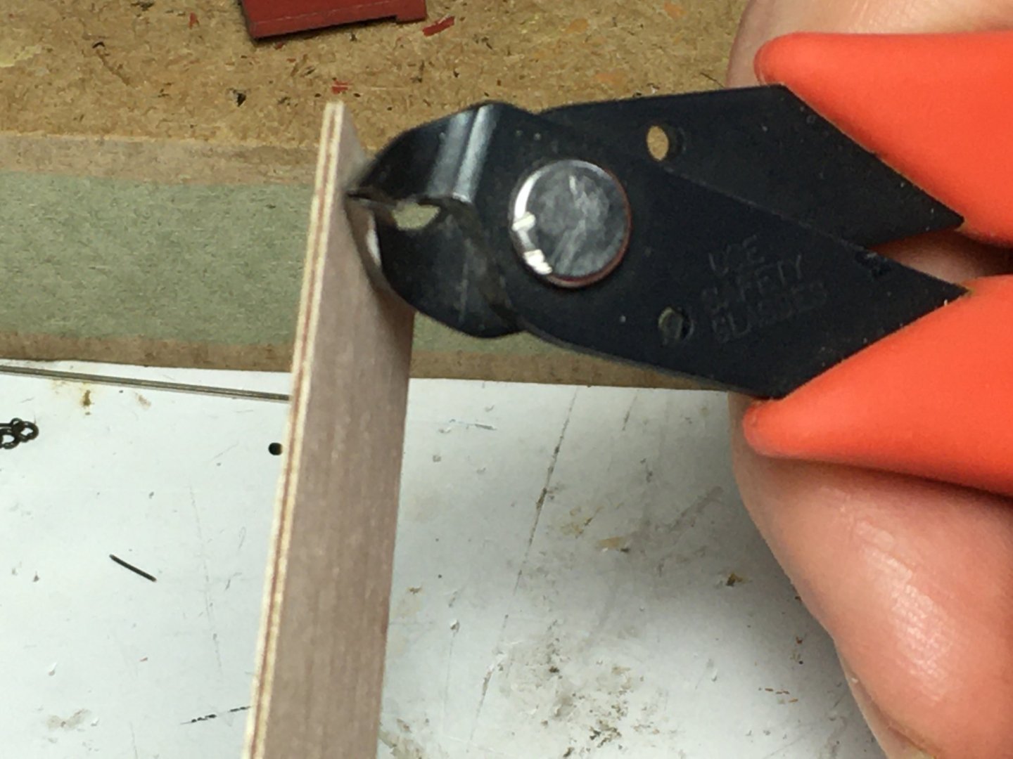
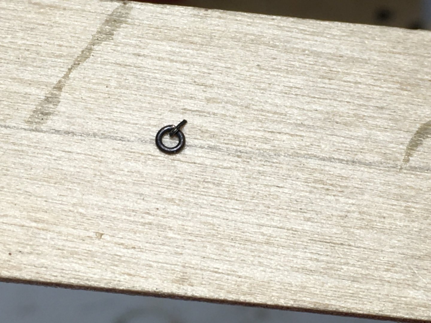
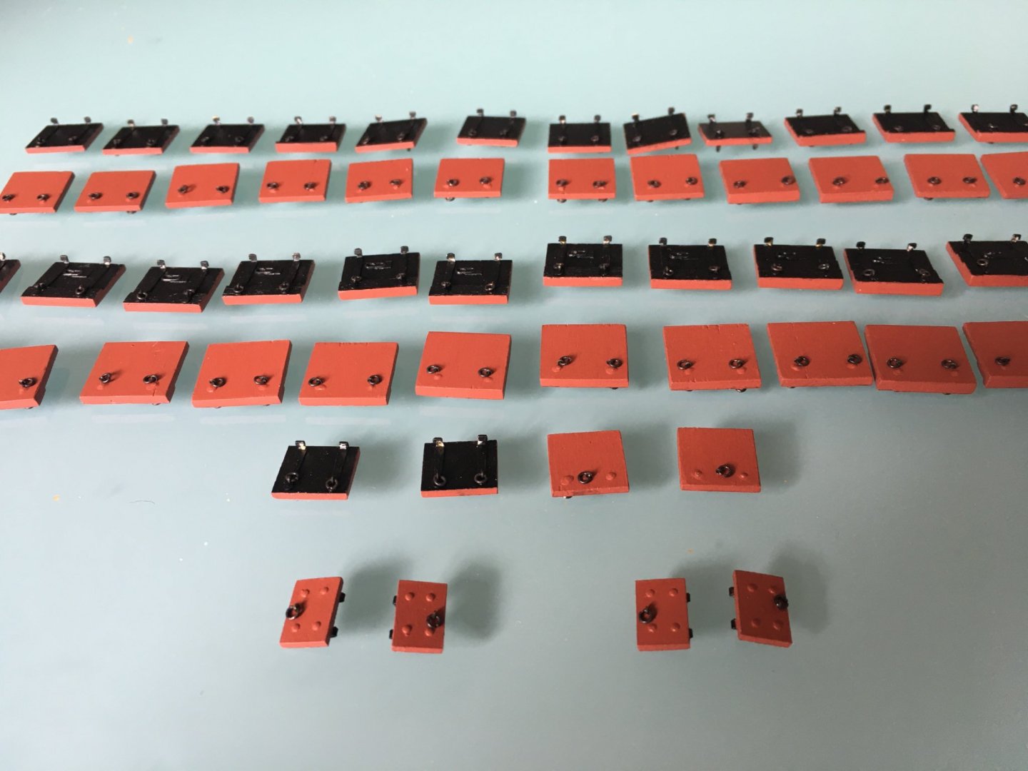
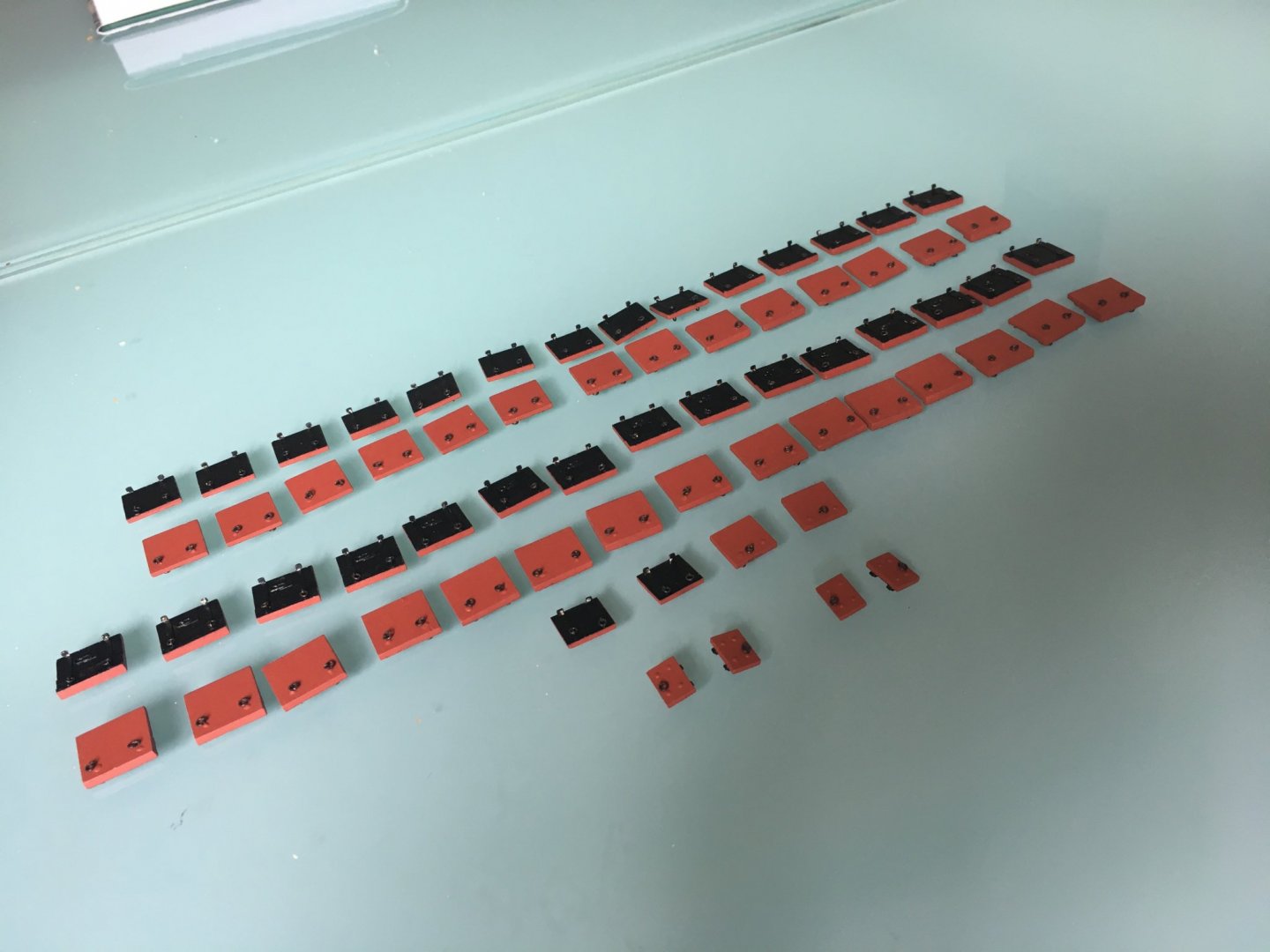
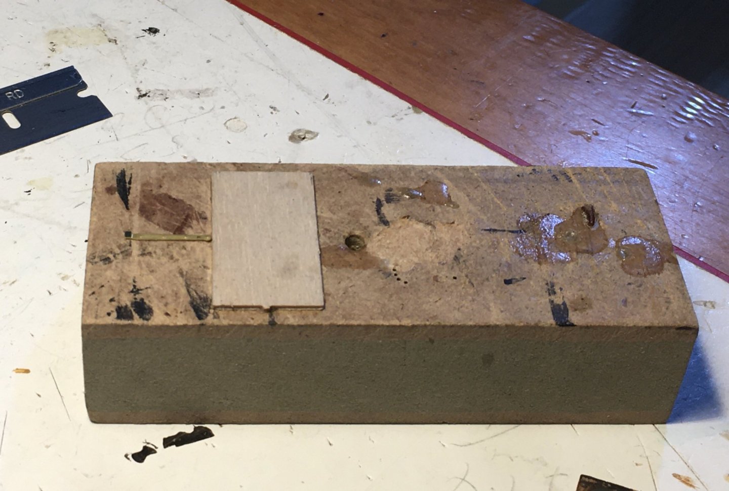
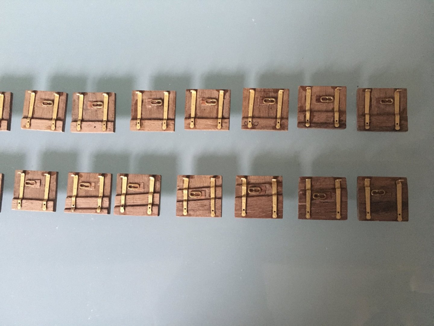
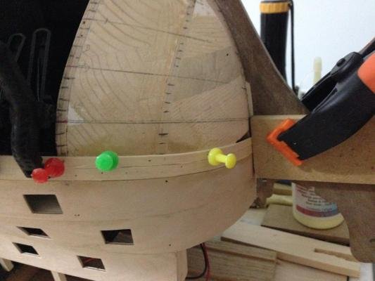
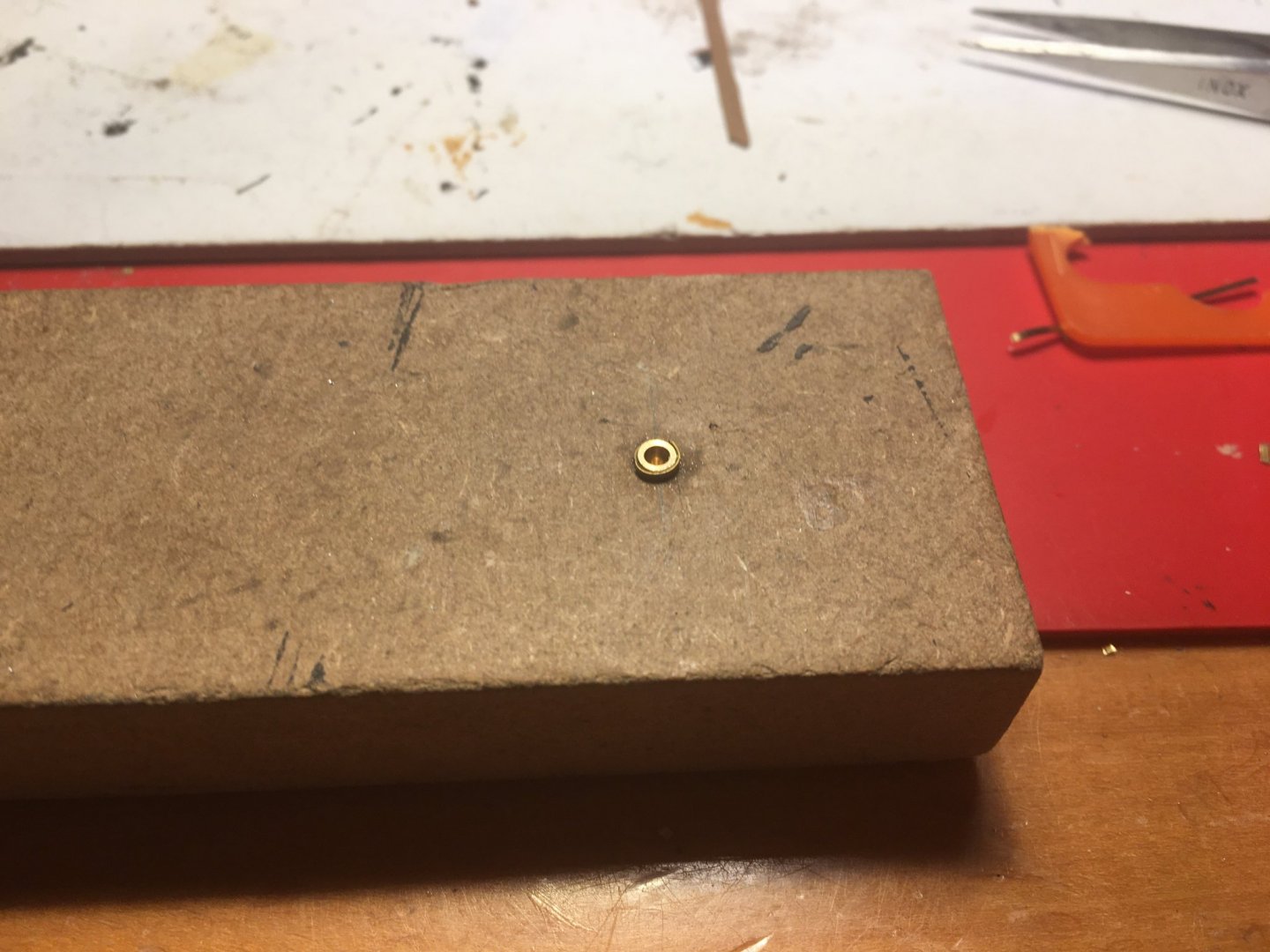
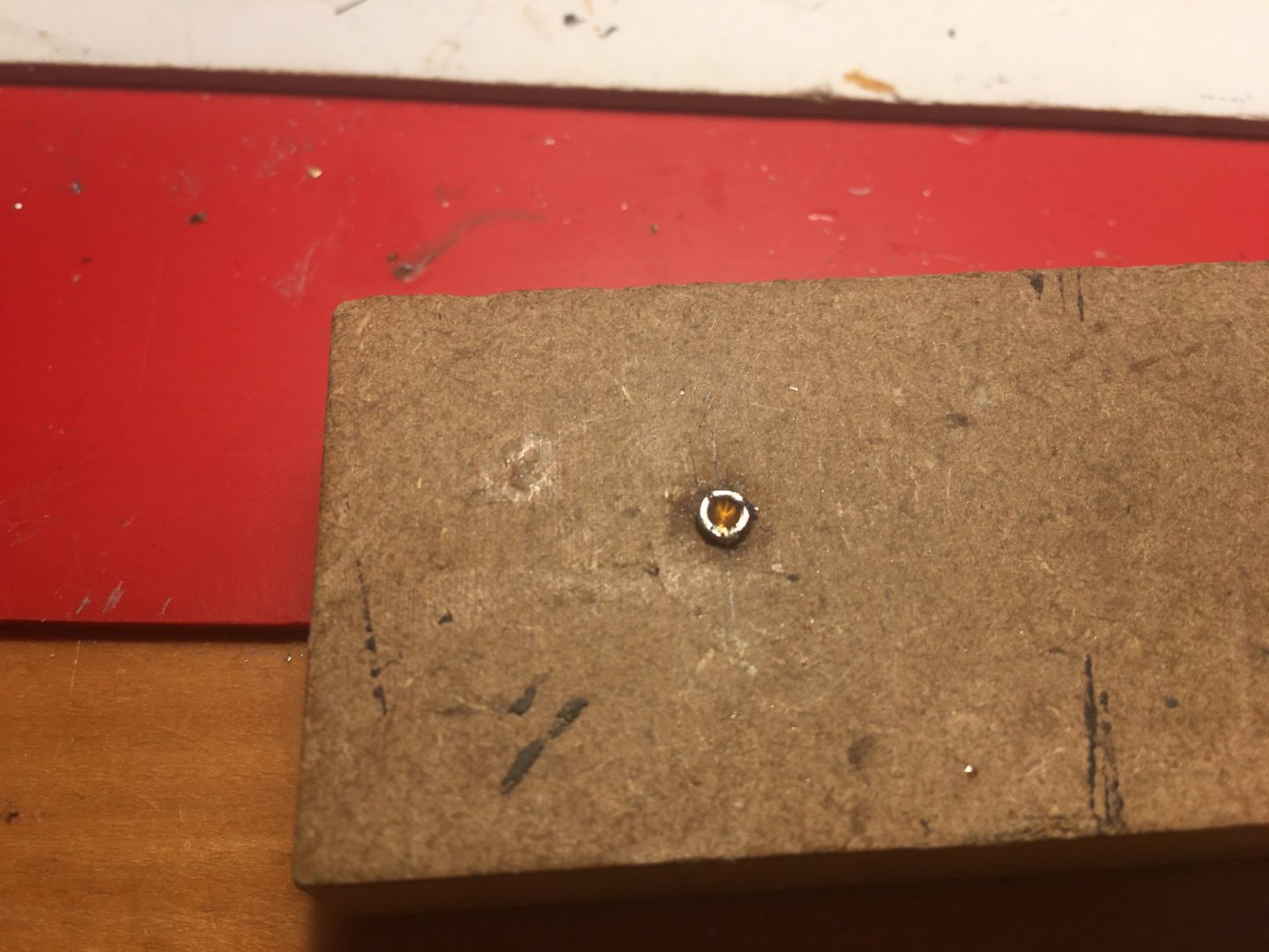
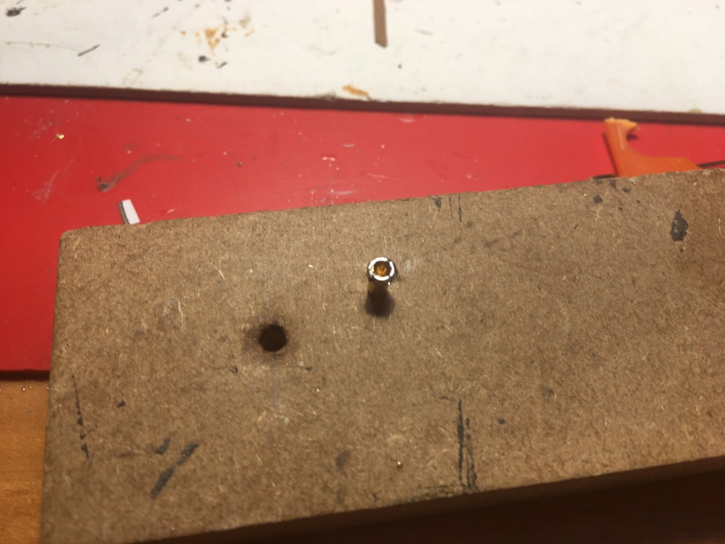
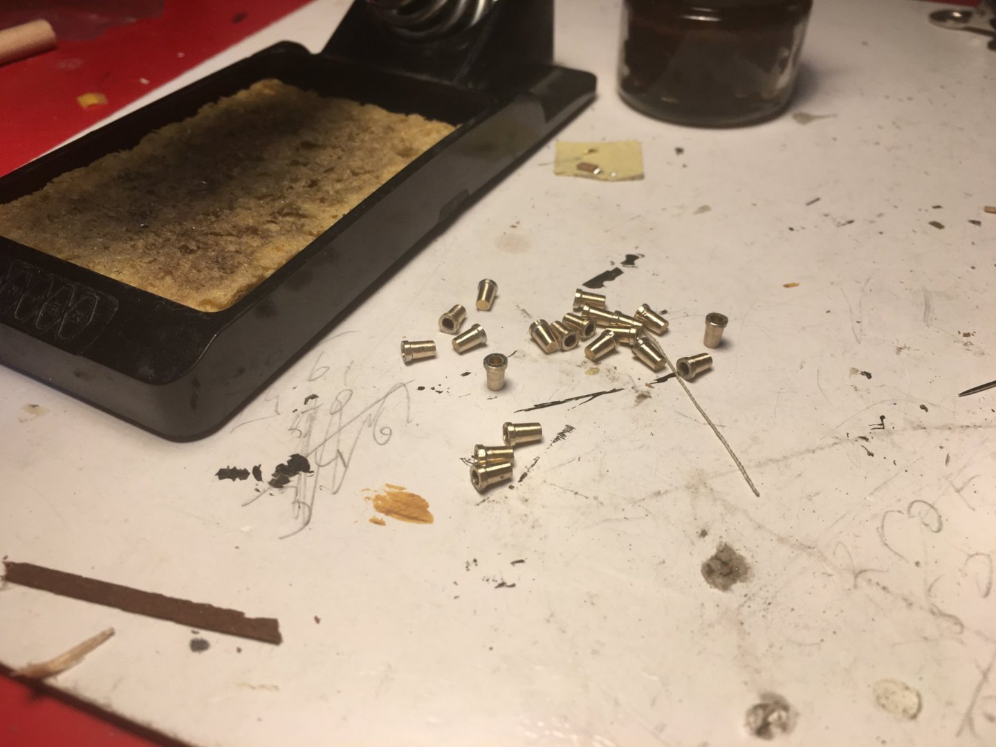
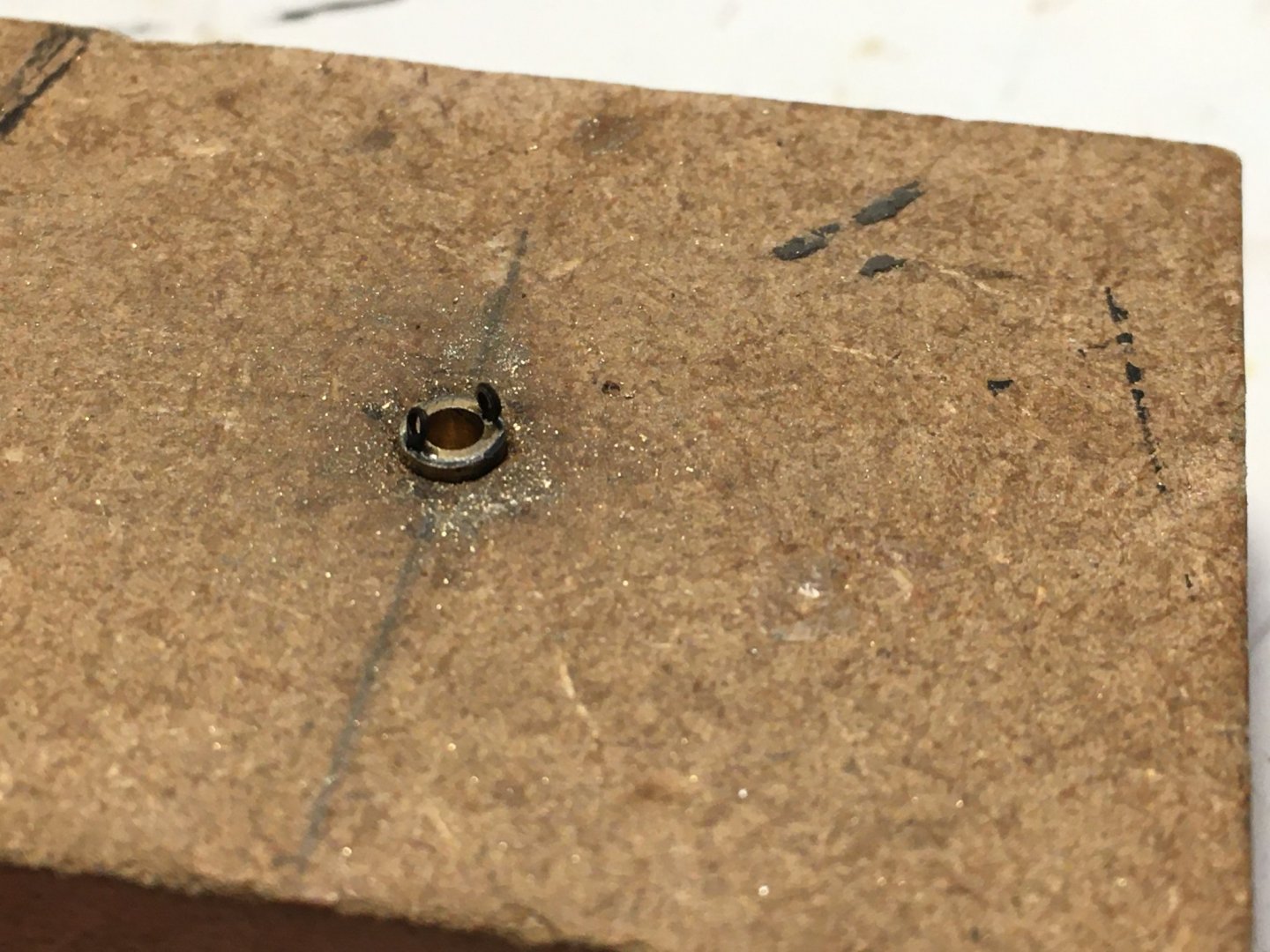
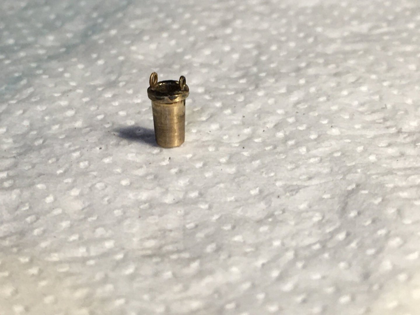
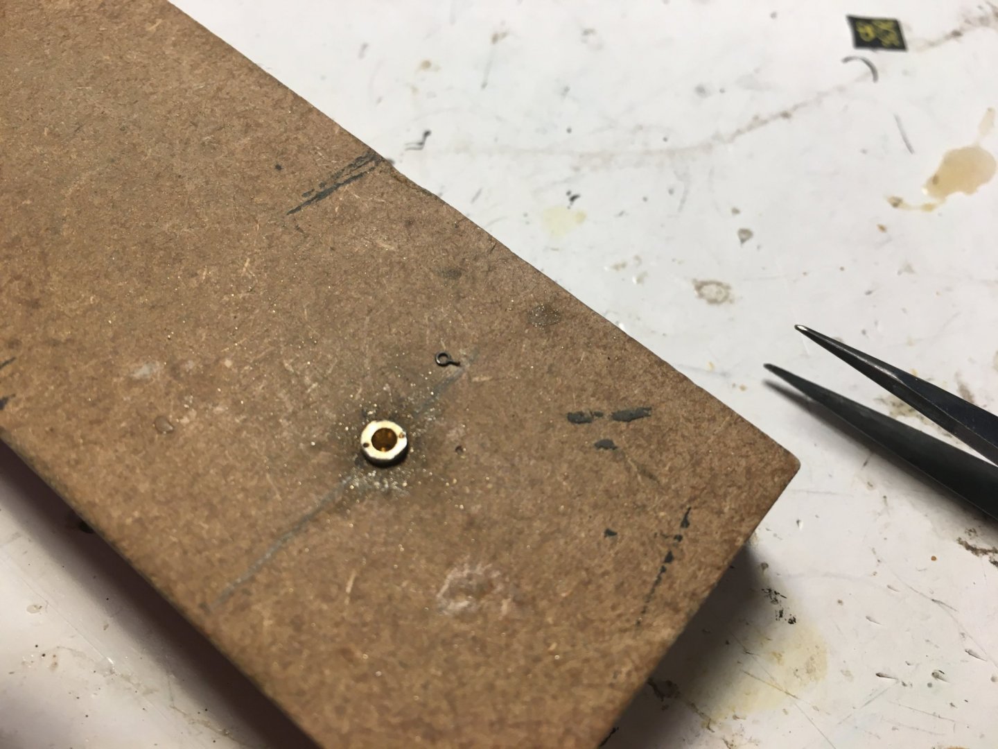
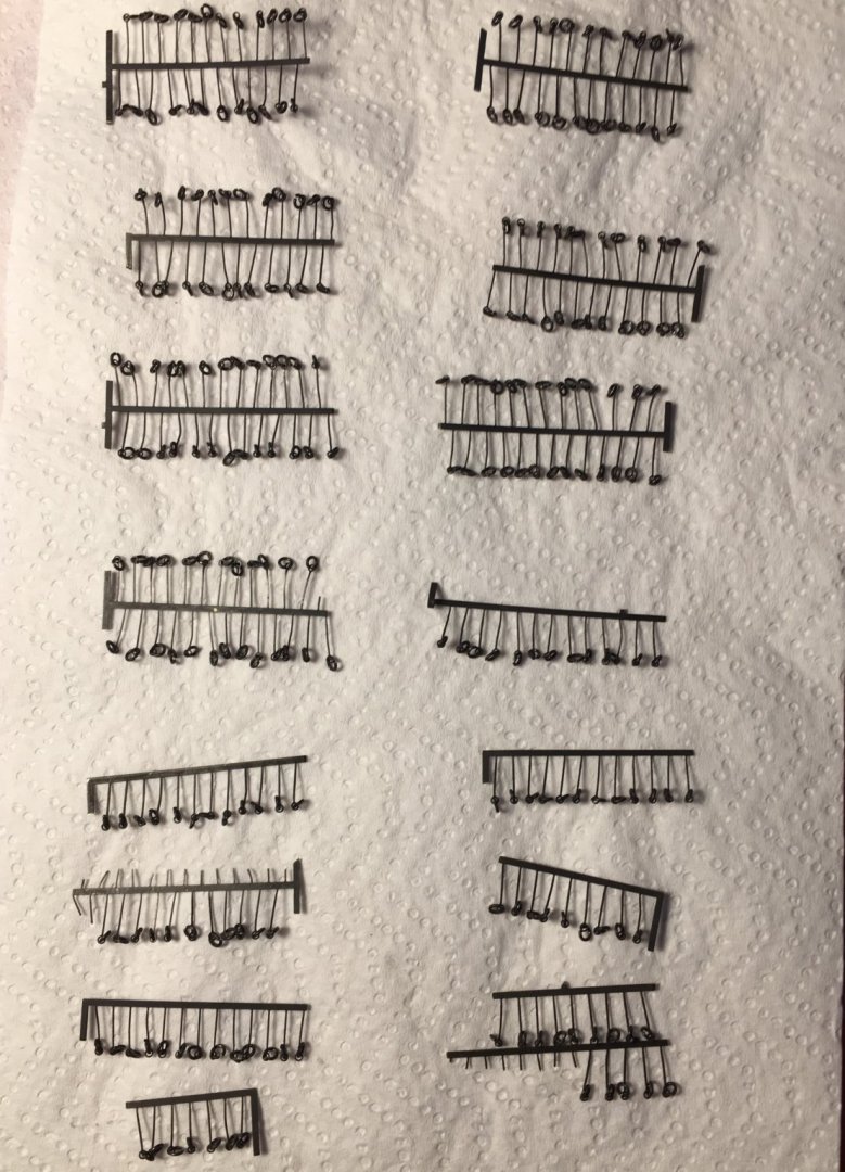
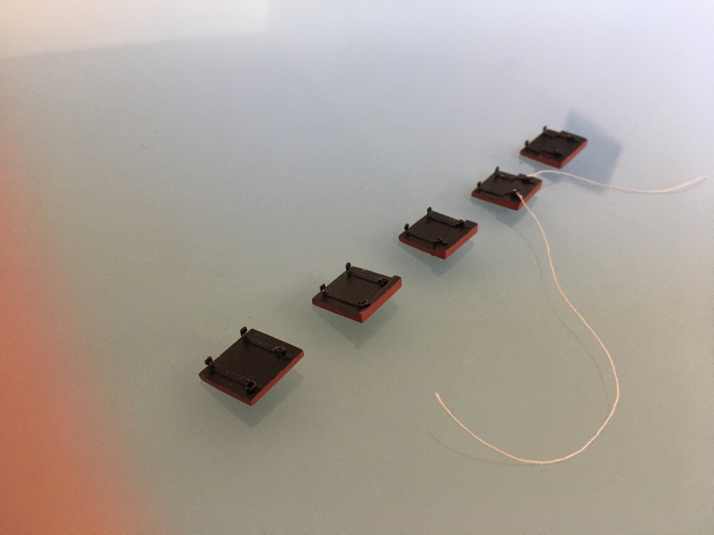
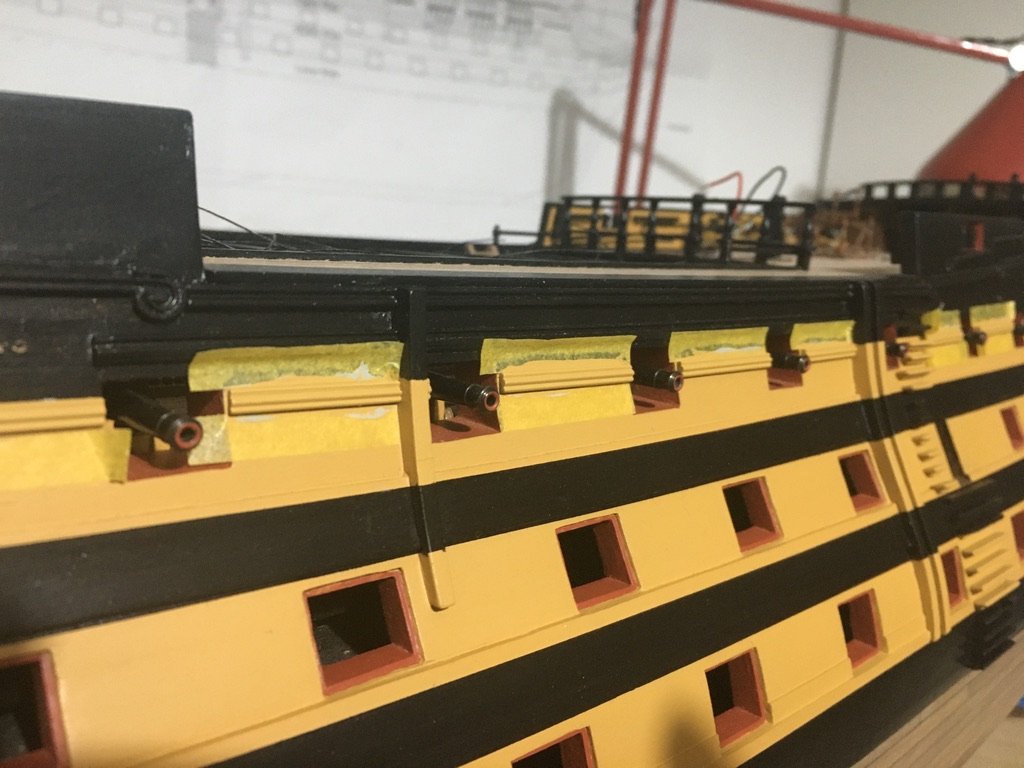
Thank you md1400cs and thank you for the likes. A small update but which is taking me a long time. The gunport lids are never ending, so much of them. I have glued the rigols in place and drilled the holes on the hull for the gunport lid ropes. To mark the holes position, I just calculated and marked them on a piece of masking tape and moved the tape from one window to the other. Instead of leaving just a hole on the hull through which I insert the thread I fitted a small piece of a very small diameter brass tube, leaving it extruding out just a bit, and the thread will pass through the tube. I blackened the brass tube pieces before fitting them in place. The width of each lid was checked to make sure it fits inside the window recess to make sure I don't have to trim them after painting them. Every lid was marked on the inside edge to indicate to which window it appertains. I had already prepared the eyelets with the rings. To cut the lengths of the eyelets all the same length without having to measure each and every one (about 250 pieces), which have to be quite short, I took a piece of plywood just a bit thinner then the lids themselves and drilled a hole in it through which the eyelet can pass easily. All I had to do was put the eyelet in the hole and with an angle cutter snip off the leg of the eyelet flash with the plywood. Lids painted and eyelets/rings all fitted in place. Now comes the laborious repetitive work of tying a piece of thread to every ring on the outside of the lids. I think it is much easier tying the thread to the rings now, with the lids in hand and inserting the other end in the hole when lid is fitted, than the other way round, that is gluing the thread in the holes on the hull and trying to tie the thread to the rings after lid is in place as actually indicated in the instruction manual. I am sure it is much more difficult trying to tie neatly the thread with the lid fitted to the hull. Hope to finish tying the thread to the rings by the end of the coming weekend!!!! Robert


- 527 replies
-
- 7
-
-
- caldercraft
- victory
- (and 1 more)
-
Hi Rich, good to see your Victory out of the box again. Always a pleasure following your build and your fine work. Robert
- 414 replies
-
- 1
-
-
- caldercraft
- victory
- (and 1 more)
-
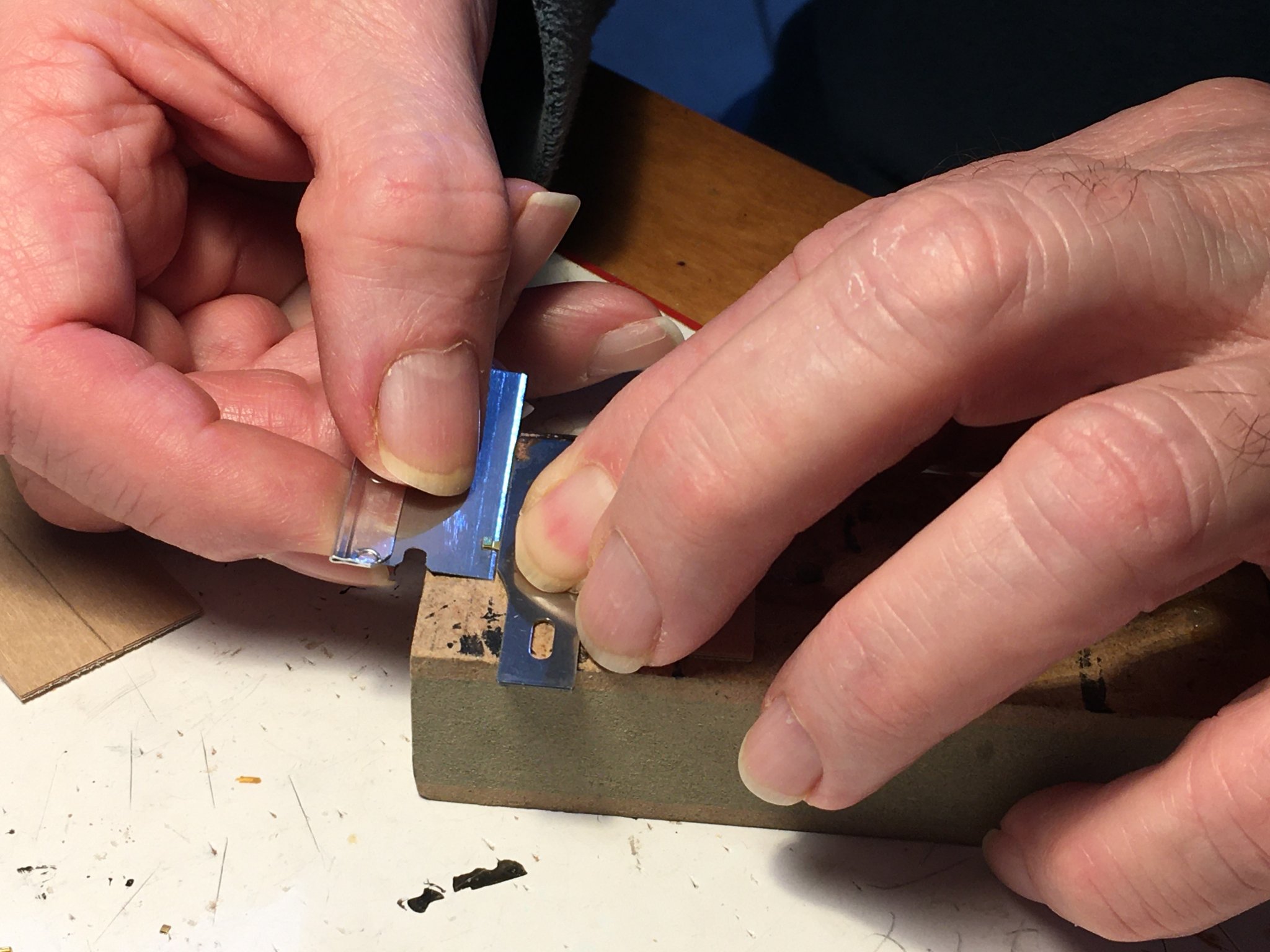
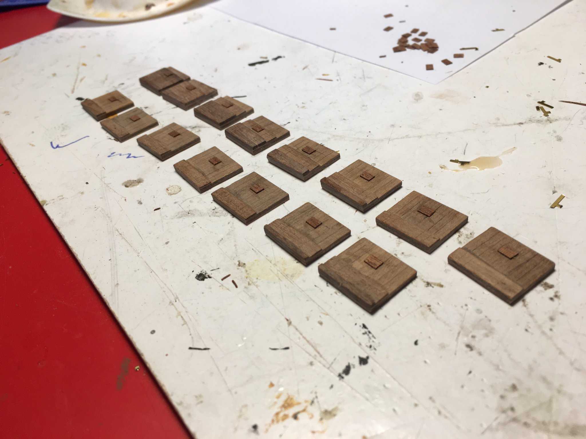
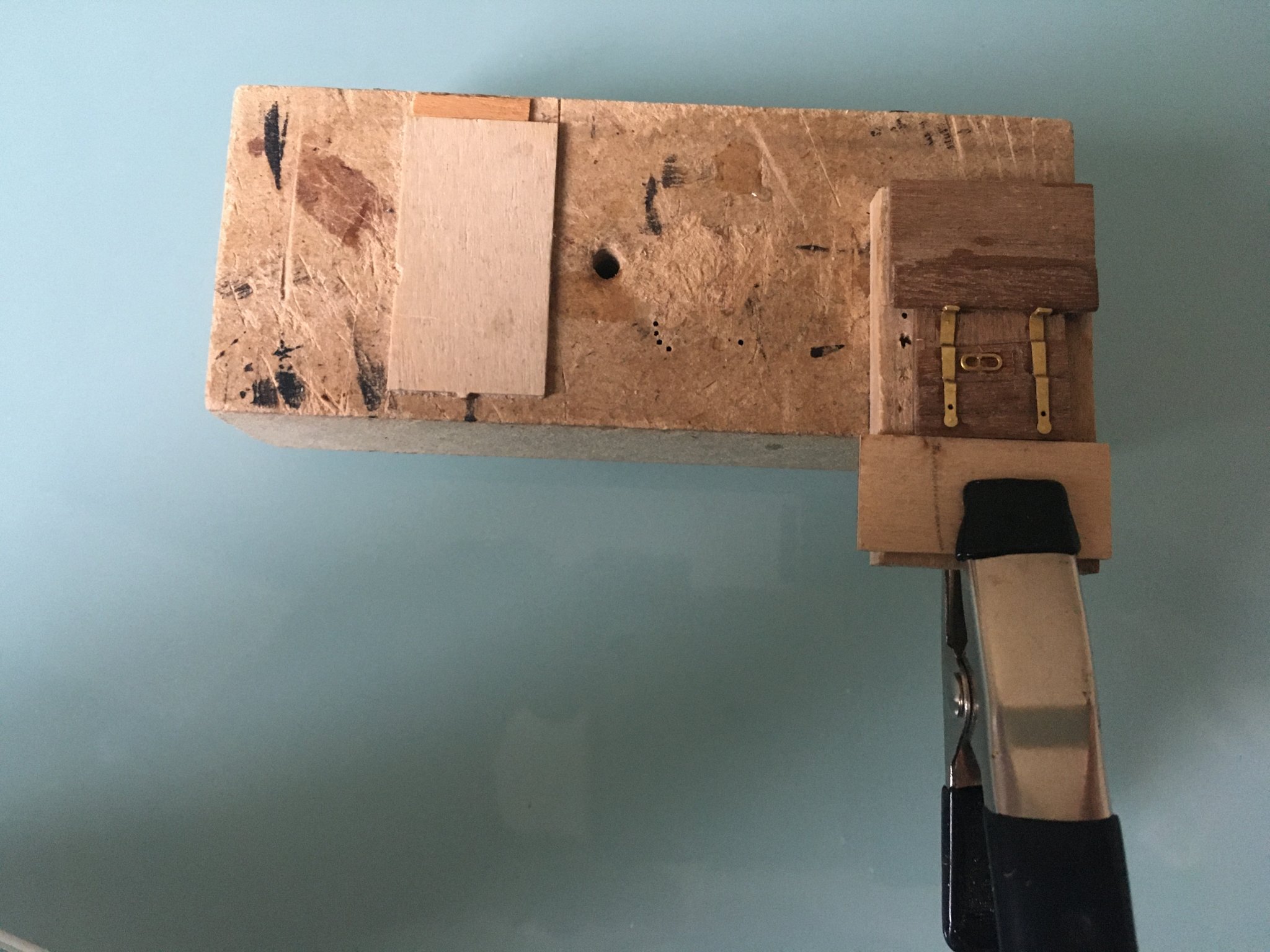
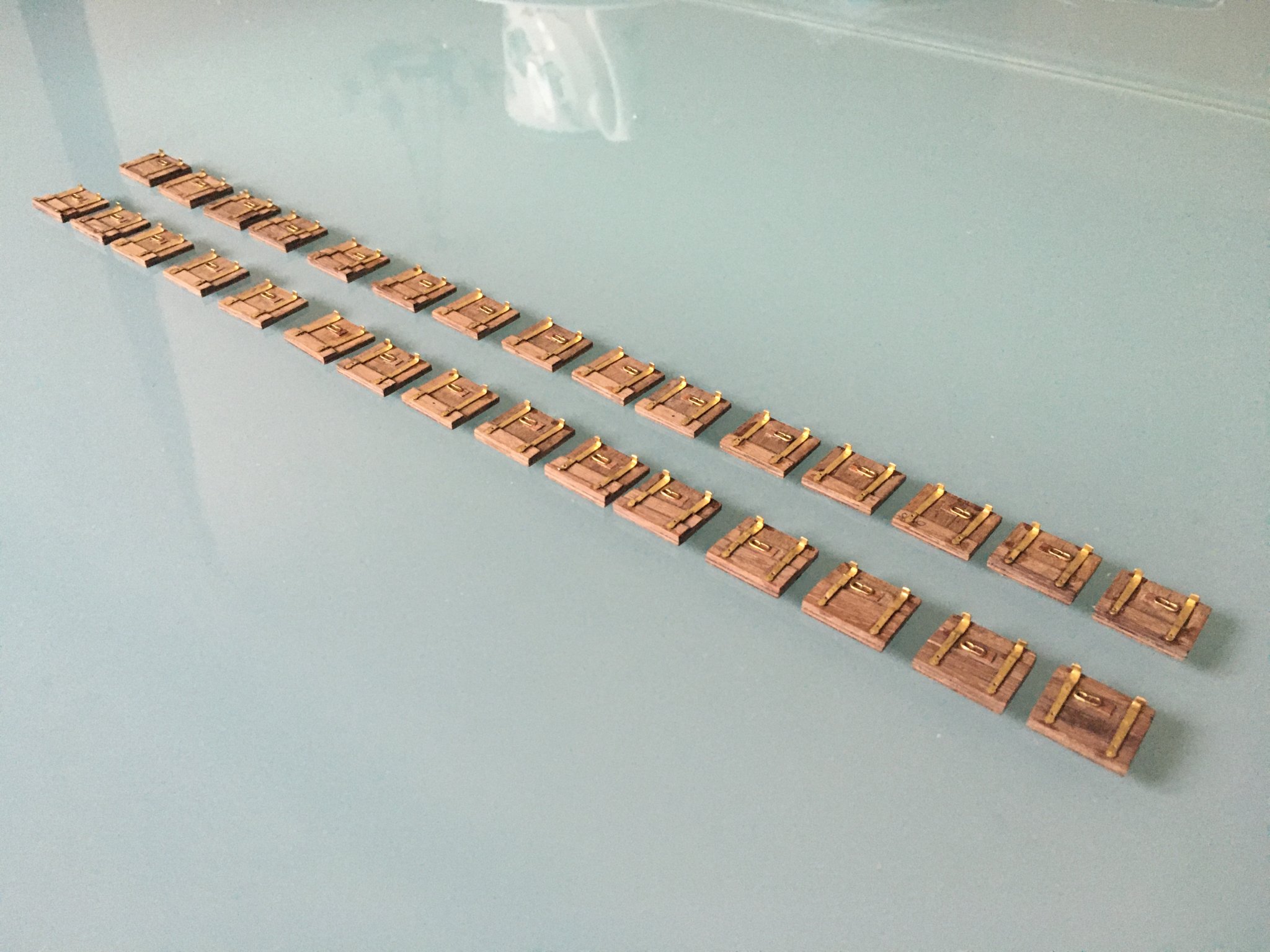
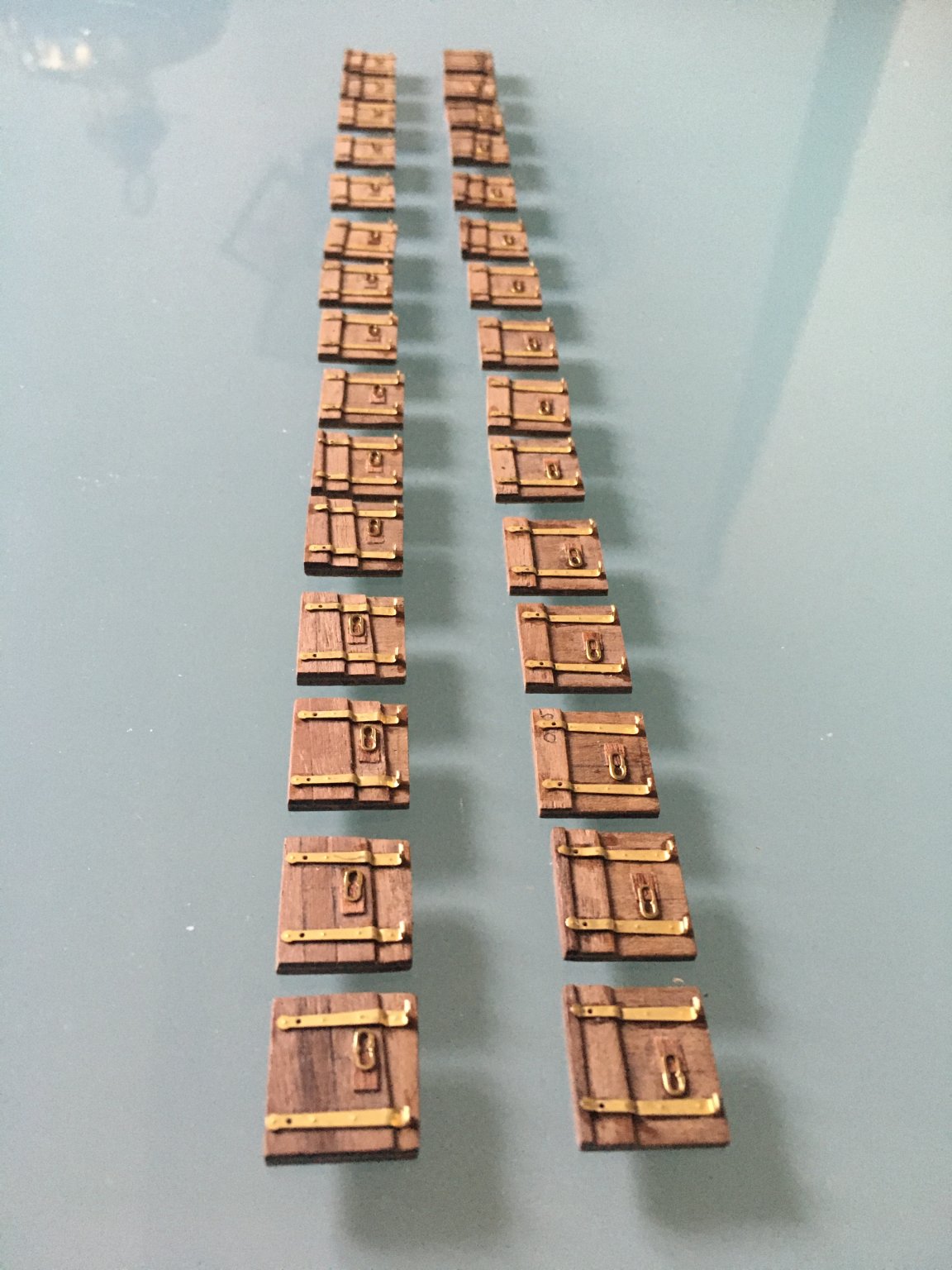
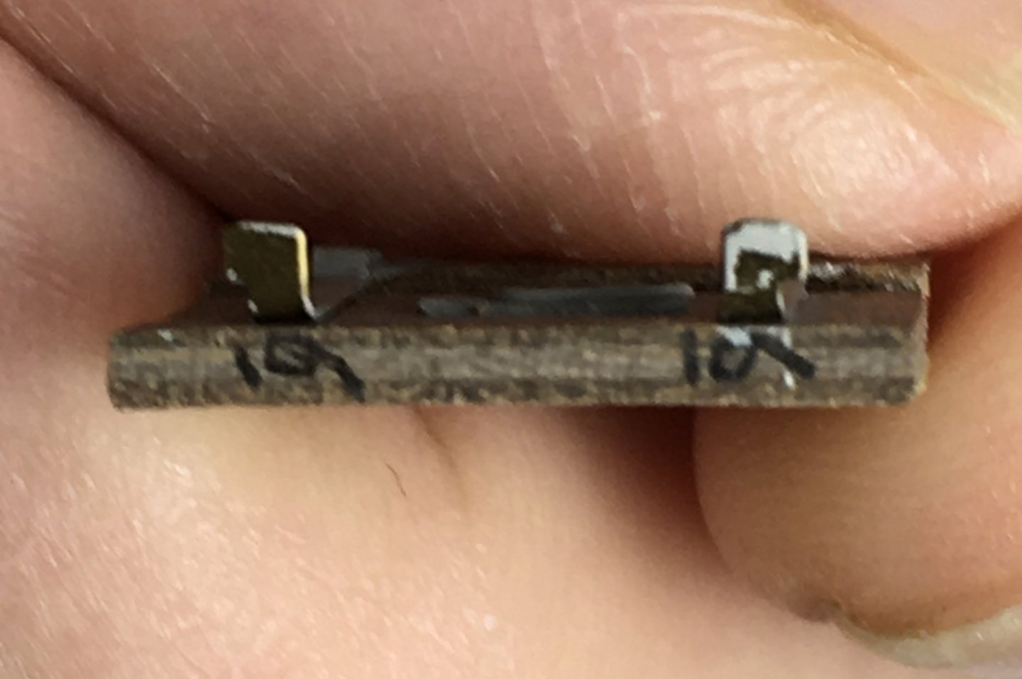
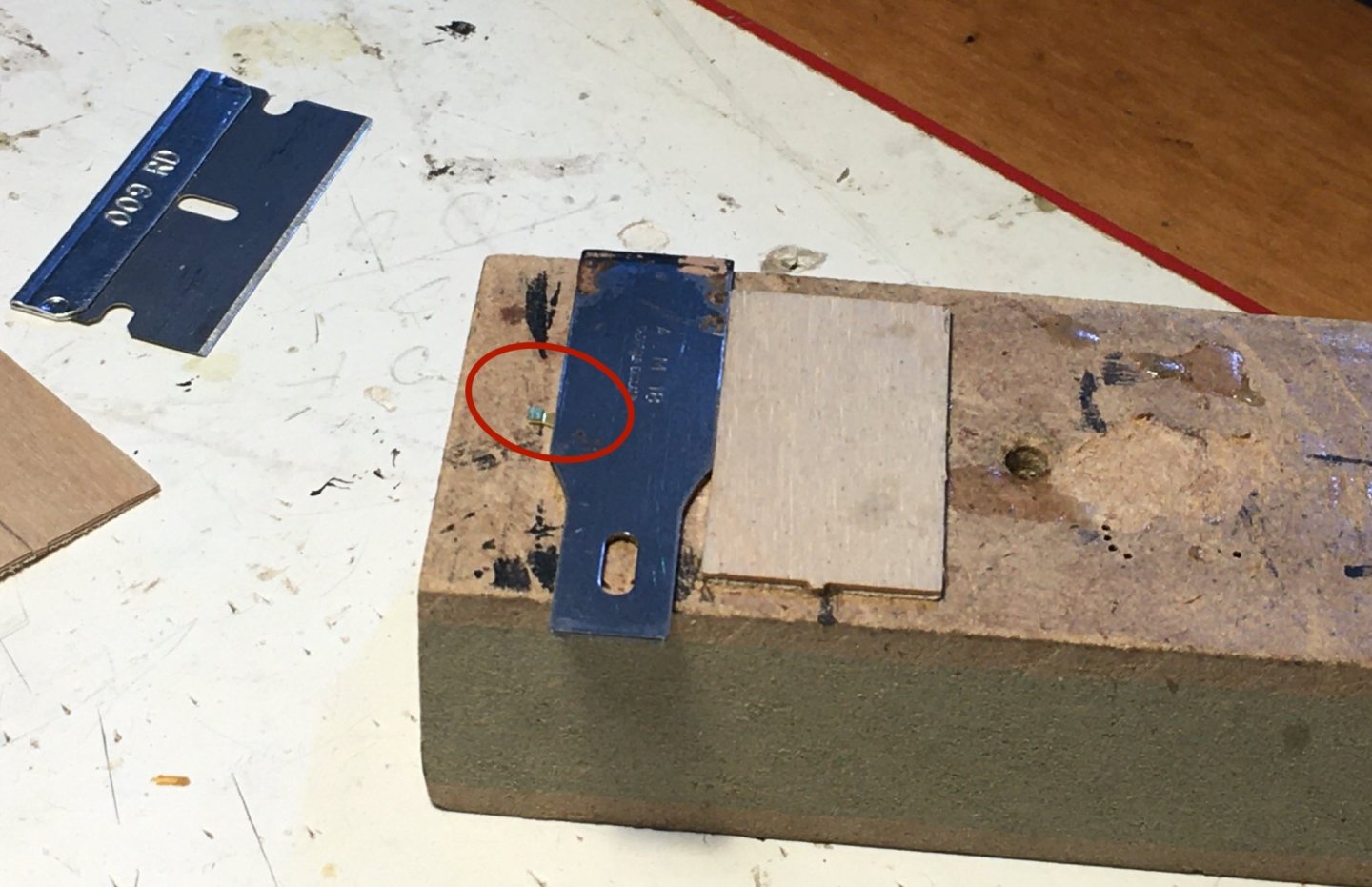
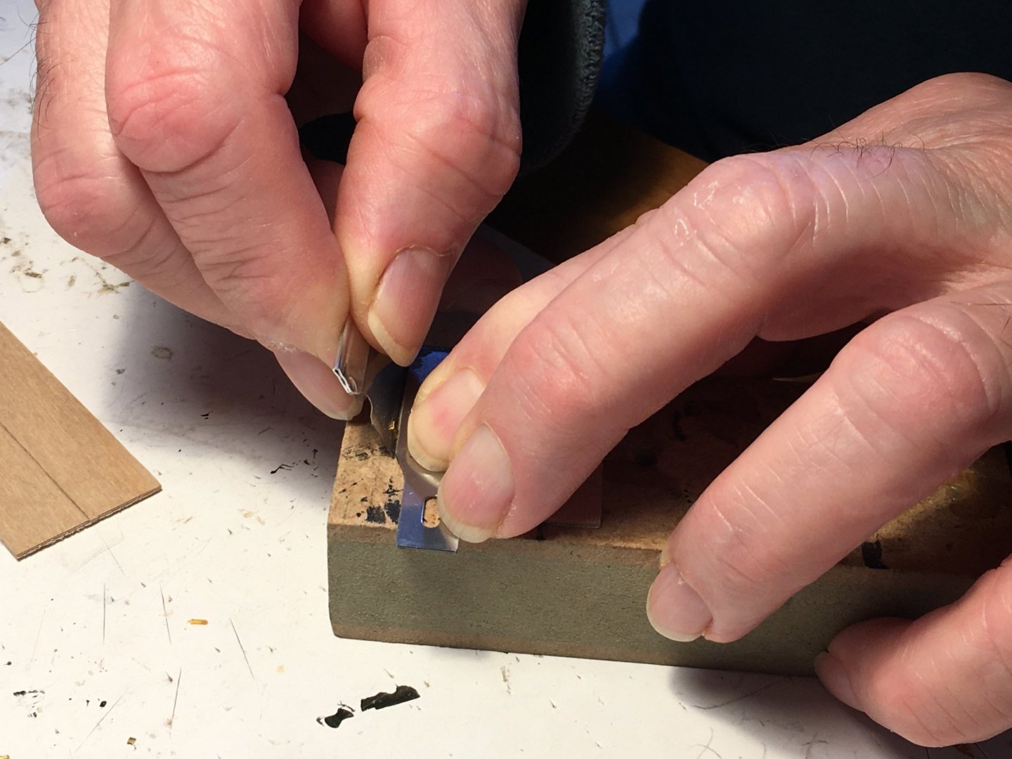
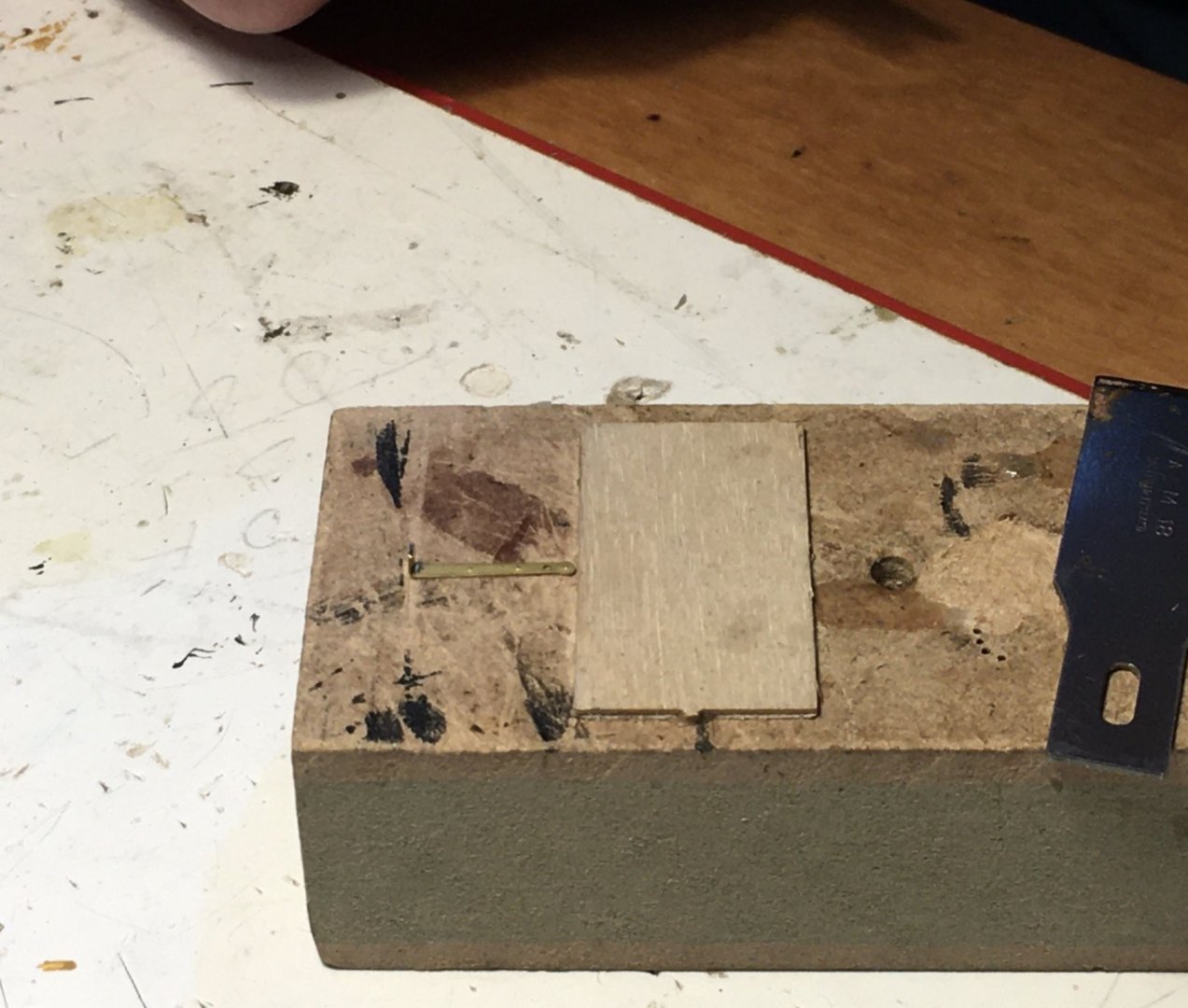
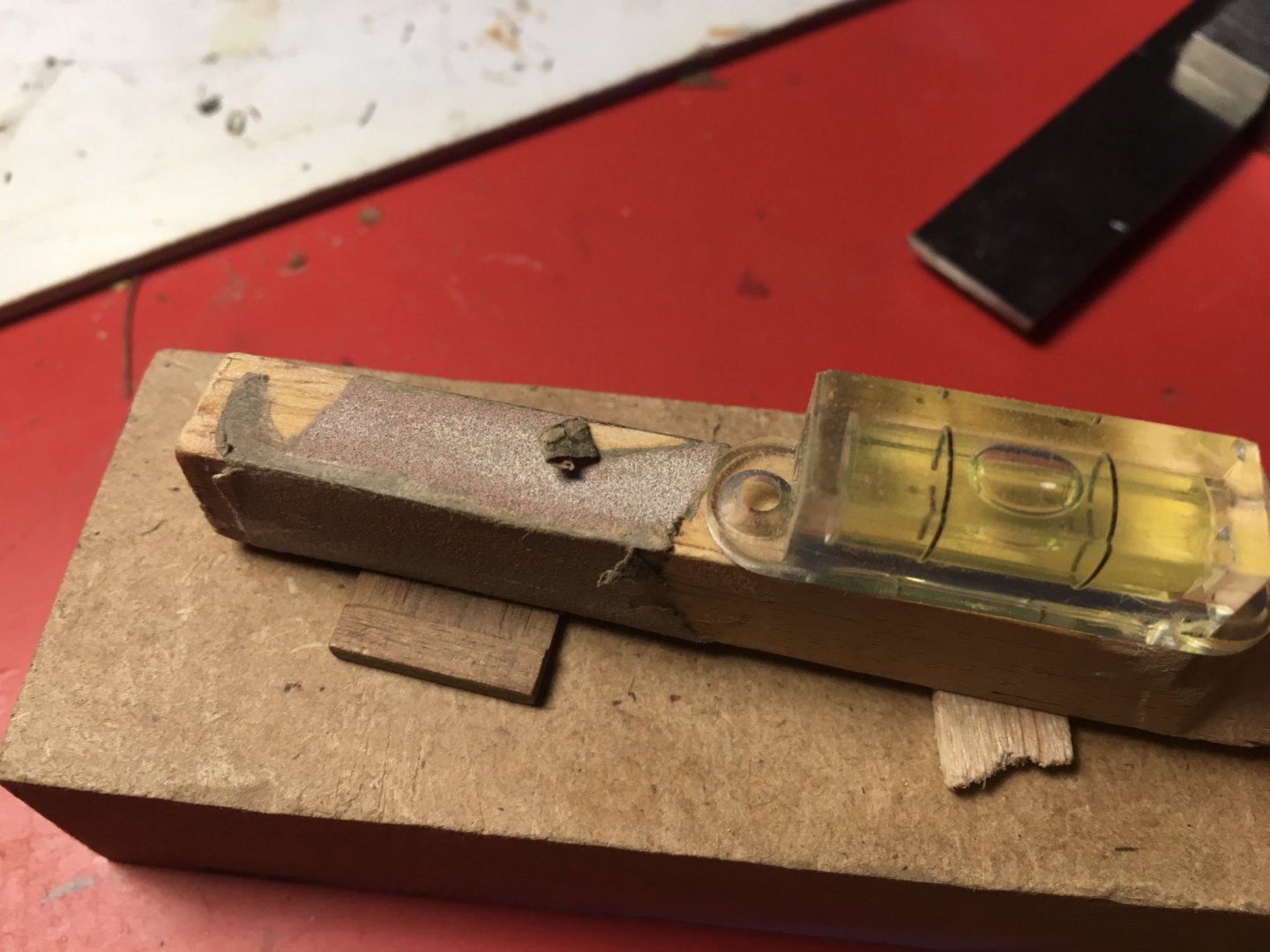
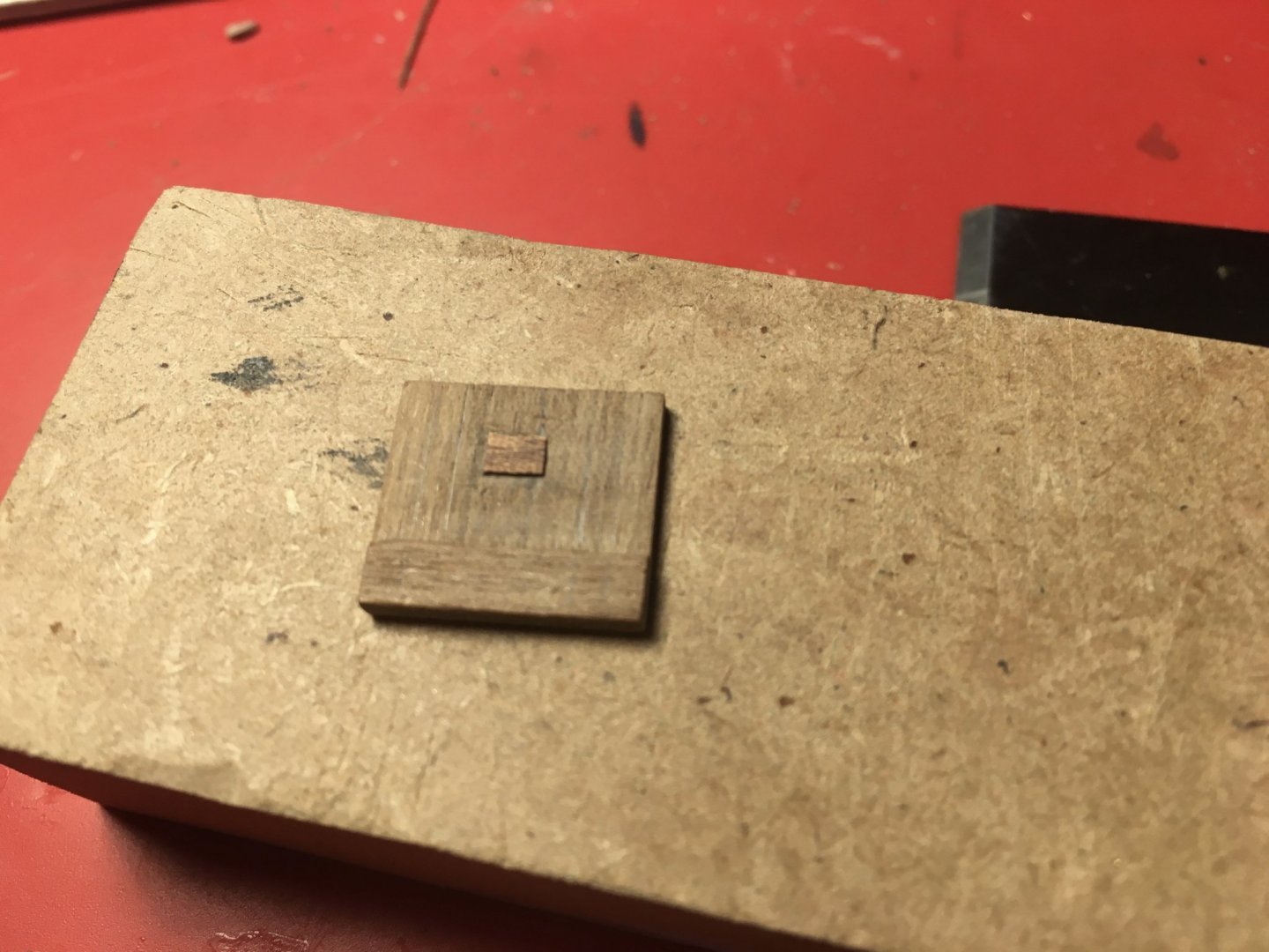
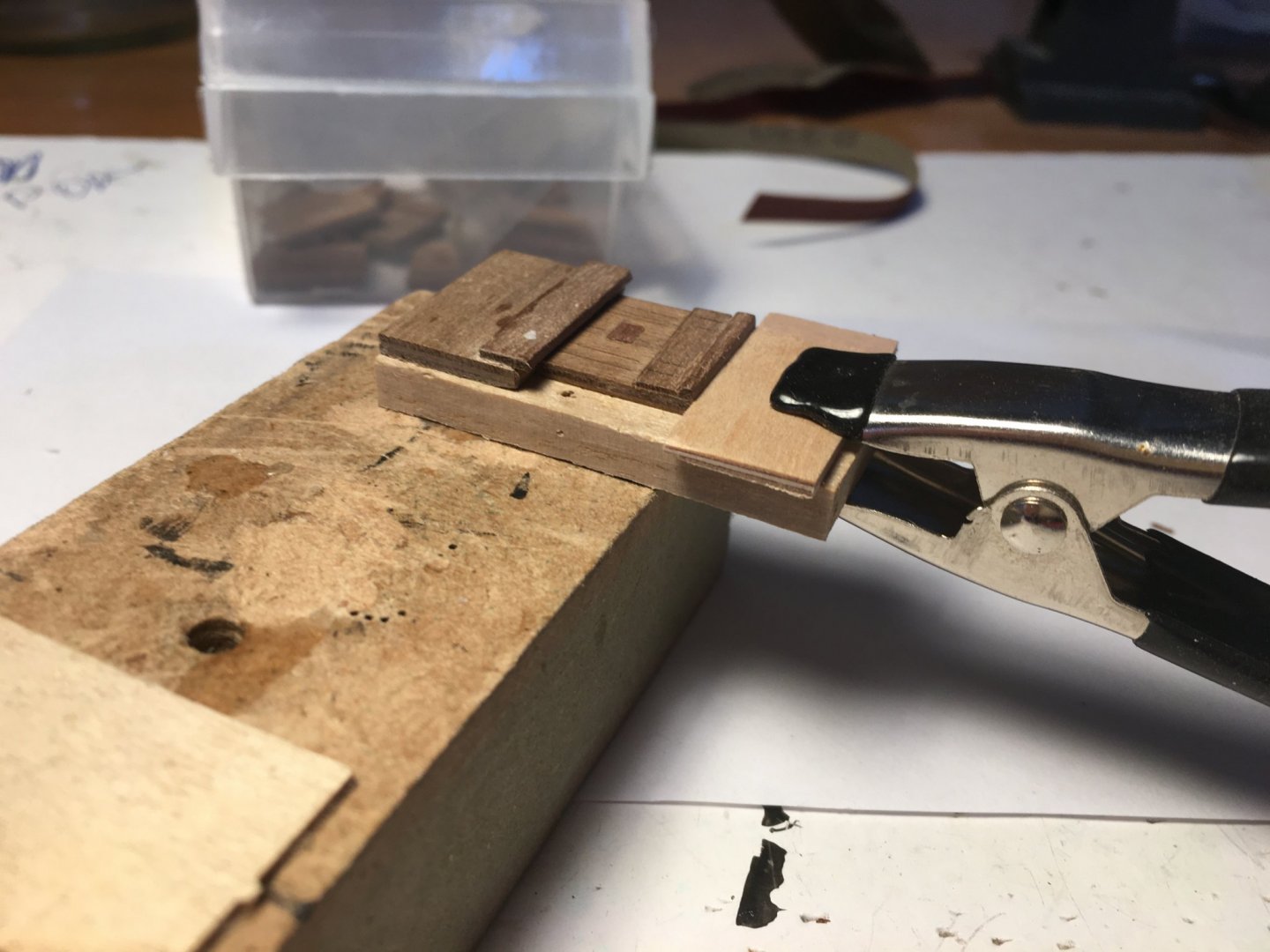
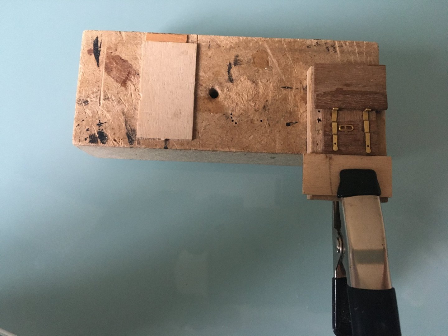
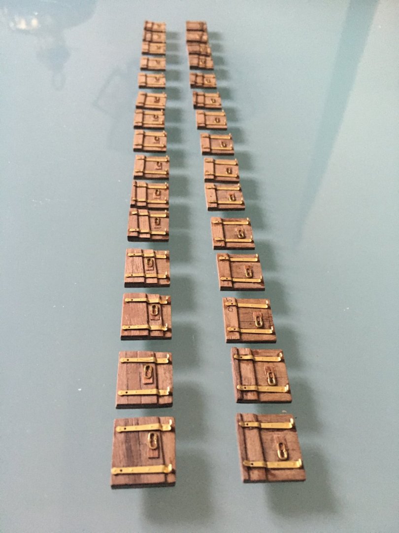
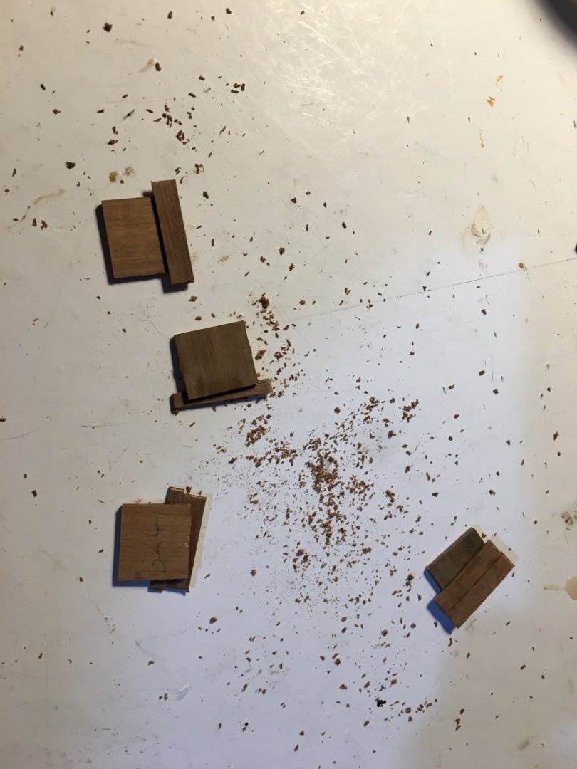
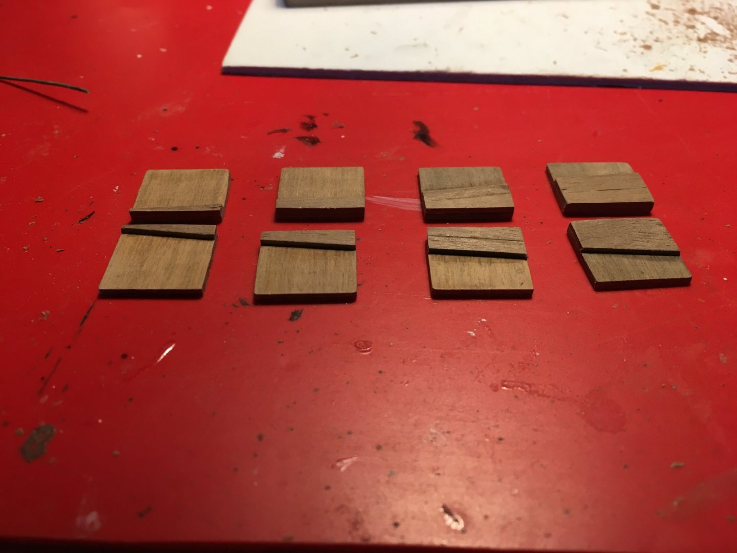
Nice comments and likes really appreciated. Gives me more courage to keep me going on the build which takes hours on hours. But its a hobby I enjoy so its worth every minute I spend on it. I am starting various ends without finishing them. Basically, knowing how fragile certain parts are and how easy to knock down a few of them while doing other work, I am preparing different parts of the fittings so I will find them ready just to fit together on the ship. I started some work on the never ending gunport lids. I started with the lower deck gunport lids. First I added pieces of planks to the lids to correspond with the wales on the hull. When a lot of repetitive work is involved I try to make some kind of a jig as basic as possible as this will be used only once and can be thrown away. I started with the hinges which needed one end bent at 90º. Glued a piece of plywood to another piece of wood as a stopper and placed the hinge against it. Find something flat, exactly the same width from the stopper to where the bend has to be, possibly made of metal to get the bend as sharp as possible. In my case I found an exacto knife blade. With a single edge razor blade bend the hinge. All hinges were bent in no time and exactly all the same. The hinges for the middle gunport lids are slightly shorter so an adjustment has to be made for the jig. Then came the scuttles. The kit manual tells you to make the scuttles from a piece of walnut 0.5mm thick, glue the hinge to it and glue the whole assembly to the lid. 0.5mm is too thick, the scuttle hinge will not sit flat on the lid. I had some thin sapele left from another kit and used it instead. It too was still a bit too thick. Instead of glueing the hinge to the scuttle and glueing it as a whole assembly I thought it would be better to glue the scuttle separately, sand it down to the required thickness in place, and then glue the hinge on top of it. To glue the gunport lid hinge leaving 1mm gap from the inner edge of the lid, the scuttles and their hinges was going to take me ages. So this is the jig I came up with to give me that 1 mm gap at the back of the lid and something to hold the lid steady without moving while glueing the small parts. Nothing elaborate, but found it very helpful. Here are the finished lower deck gunport lids all ready to be painted. I also drilled the holes for the eyelets which I will fit after painting the lids. Robert


- 527 replies
-
- 12
-
-
- caldercraft
- victory
- (and 1 more)
-
Really nice detailed work Graham. The template and the copper wire idea is great. I've got quite a few of thick copper wires but never crossed my mind to use them for the job. When doing mine , as you have said, it was very difficult to bend the thin wood strips in such a short radius without breaking. Robert
-
Rob, yes that is exactly what I meant as regards bending. To taper the planks I used a combination of a planer ( I have a David planer) and sanding. The planer is useful when you have to remove a substantial amount of wood and sanding is better to remove small amounts. What I had found useful was, in between the marked bands I also marked where each individual plank is going to be on every bulkhead. This helped a lot, especially when you taper a bit too much or too little at any particular place you would know and can compensate for the difference with the next plank. I am inserting a couple of iimages from my build, if you want I can remove. Robert
-
Hi Rob, sorry I meant flatwise not flatware. What I mean is bending across the tickness of the plank. Whilst edgewise I meant bending laterally across its it's width, which is more difficult. Actually the proper way is to go for what is called 'spiling'. This is used instead of edge bending (across the width). Basically this is done by getting wider planks and cutting the planks to shape instead of bending them. But you will not find the wider planks needed for spiling with any kit. You have to buy them separate and you have a lot of waste. I find nothing wrong with edge bending unless the curve is too sharp, otherwise you might get what is called the clinker effect, i.e the outer edge of the bend tends to overlap the plank next to it. Always taper on the same side of the plank. For example if you are holding the boat upside down to plank the hull taper the top edge and leave the other edge straight. Next plank , again taper the top edge. This way you will always have a straight edge against which to mate the tapered edge.This way you shouldn't get any gaps. You are more likely to get gaps if you have the taper edges facing each other. Hope I am not confusing you. There is a good right up on planking in this same forum. It's worth reading. It's in the articles/downloads - ship model framing and planking - simple hull planking for beginners. plankingprojectbeginners.pdf Robert
-
Hi Rob, I am currently building the Caldercraft HMS Victory and planking took me a long time, planning, measuring, soaking, glueing etc. I can give you a few hints that I learned throughout my planking period. A tool I found very useful was the Amati Electric Plank Bender. Sometimes if bending flatware you don't even have to soak the plank. But if you are bending edgewise you have to soak them. I never glued planks in place while they were still soaked. Wood expands when soaked and contracts again when it dries. So glueing soaked planks, when they dry they will probably leave a gap from adjacent planks. I used to soak them, bend them to shape, pin them in place temporarily until they are dry. When dry take it off, it should retain the same shape. If need trim to make perfect fit. It is very easy to soak long planks. From any ironmonger buy a piece of PVC drain pipe, maybe 30mm diameter, and a stopper for the same pipe. Seal one end with the stopper, keep it upright and fill with water. You only have to be careful where to keep it, because of its small diameter and long shape it topples very easily. It is best to secure it with something. You can make it any length you want and it is very cheap to make. Hope this helps you and good luck on your build. Robert
-
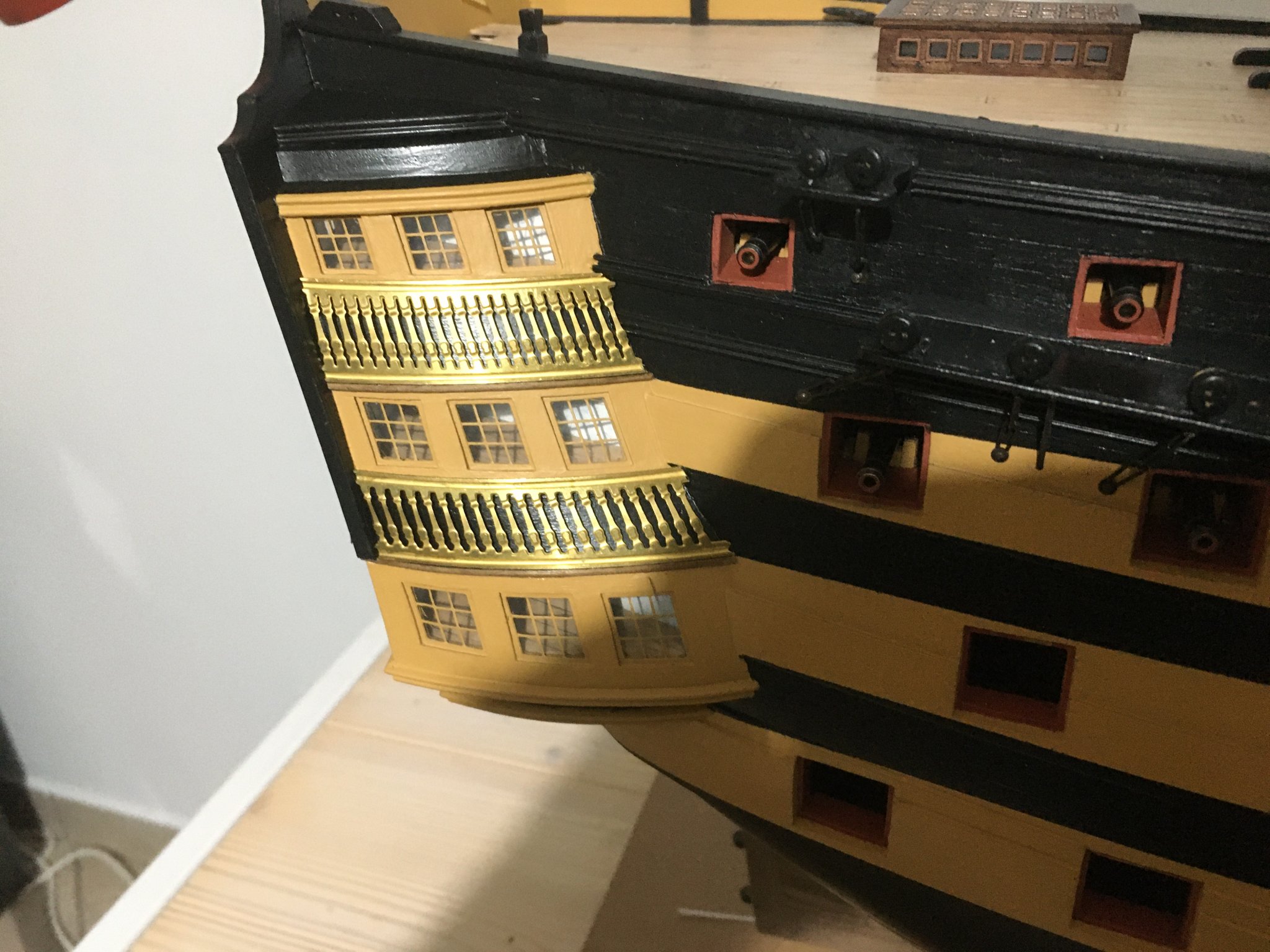
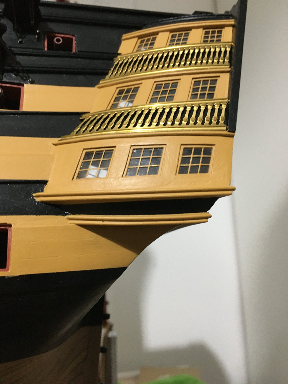
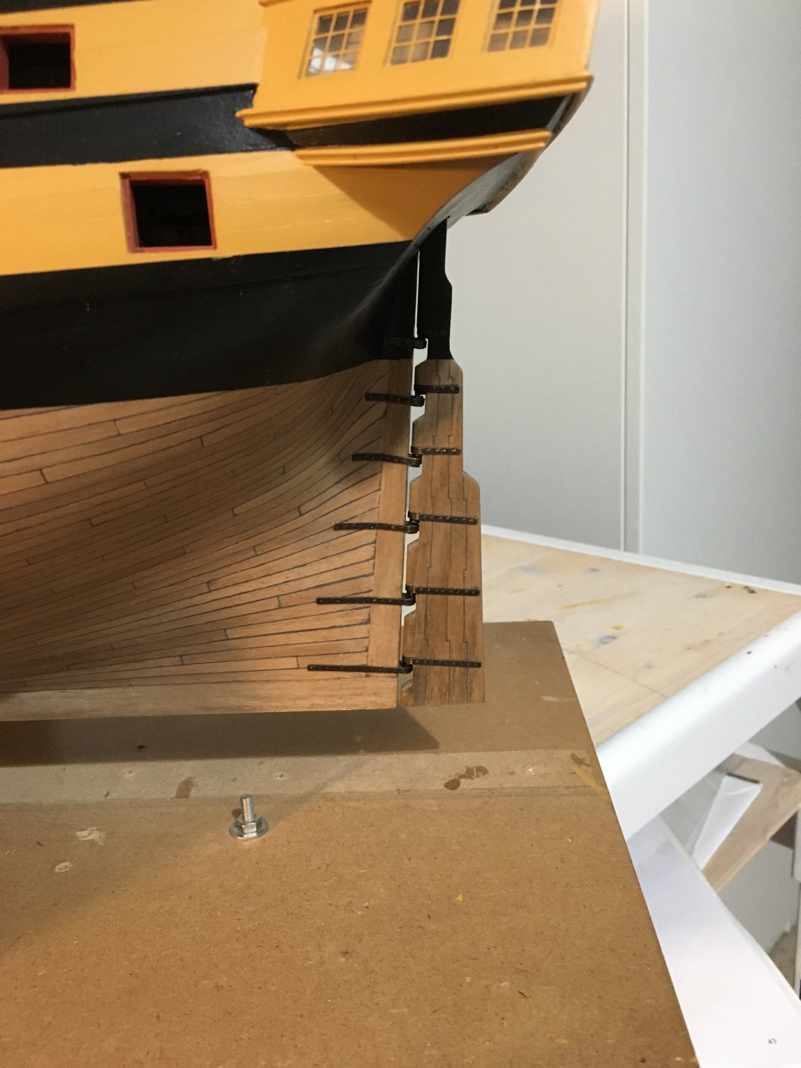
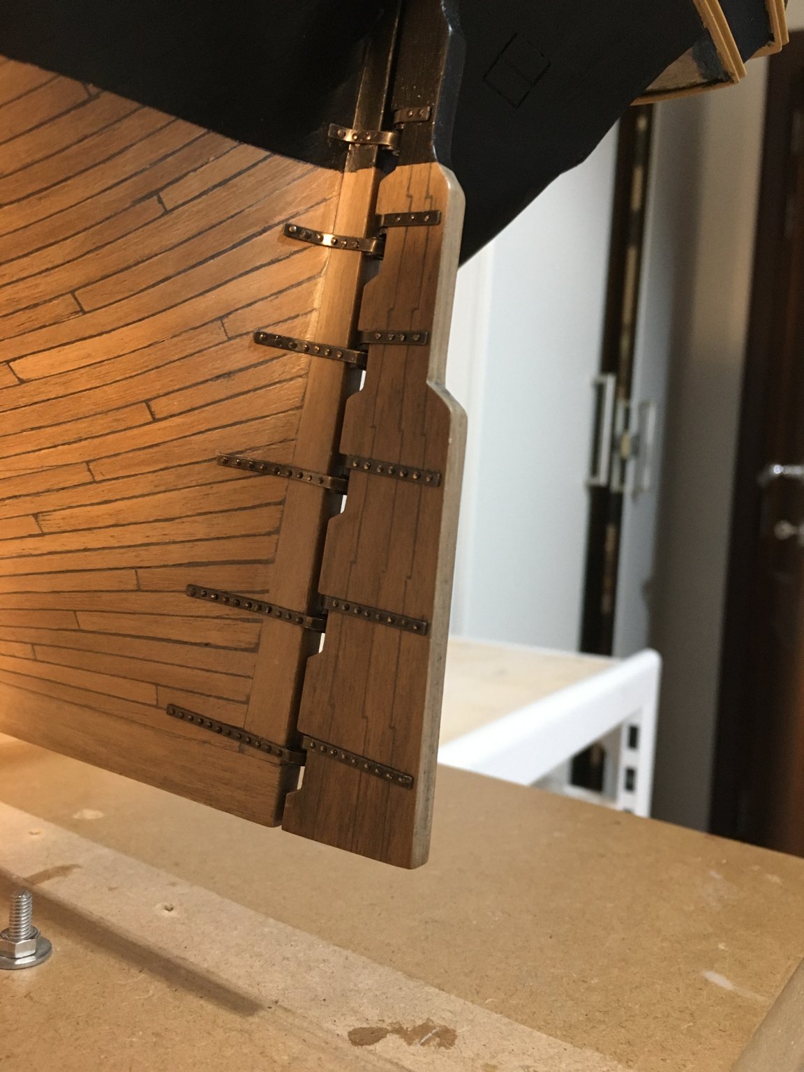
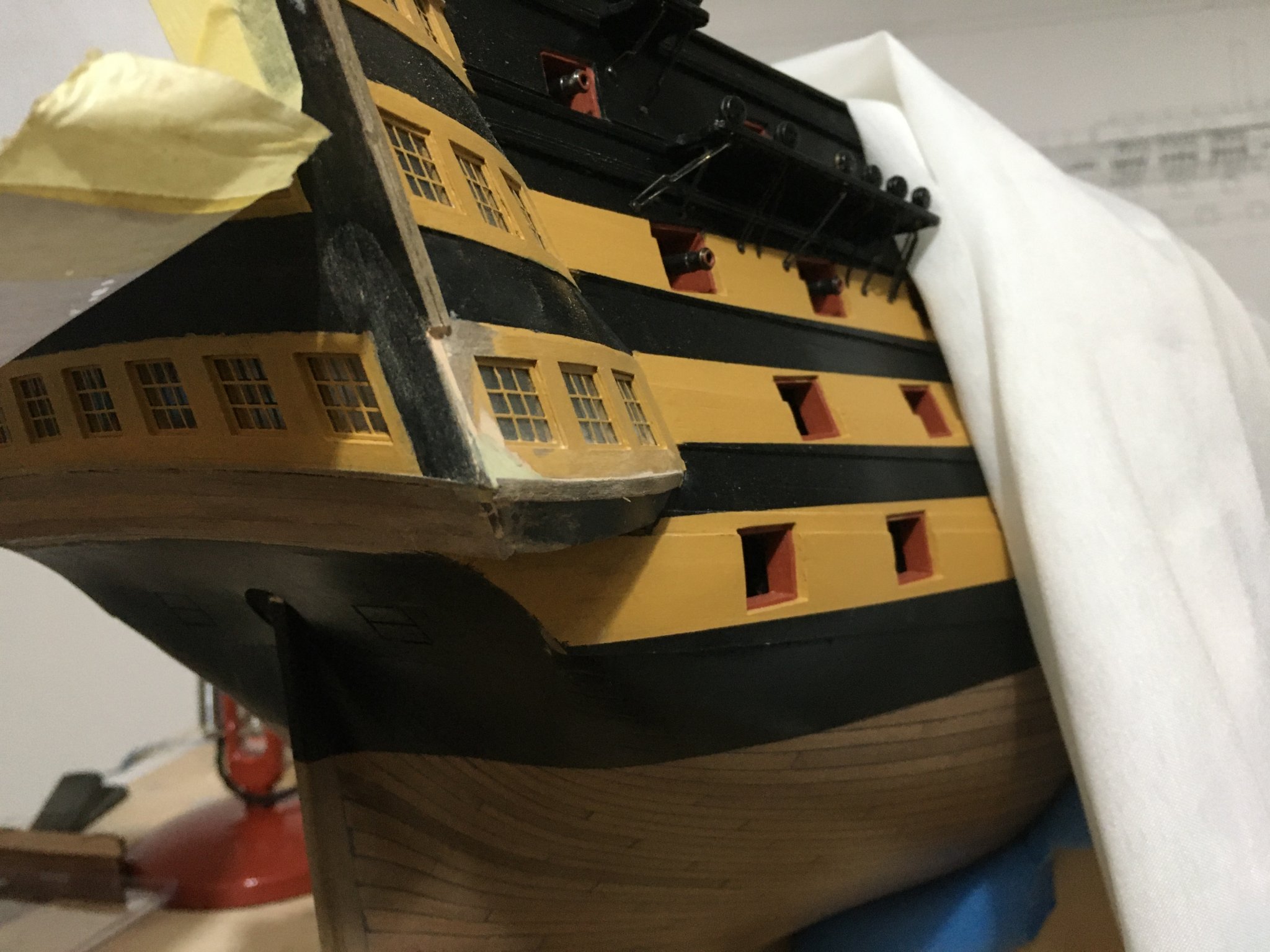
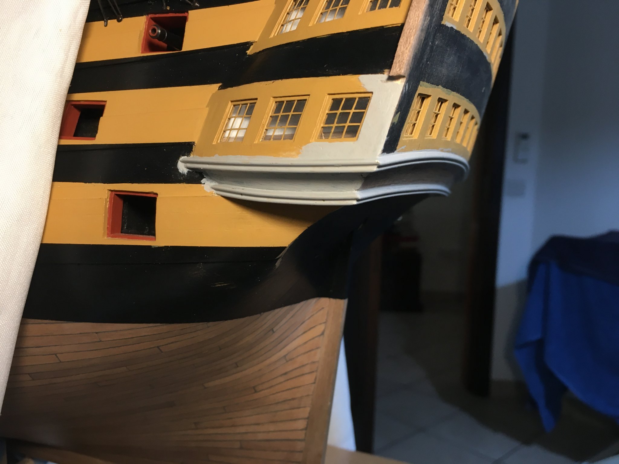
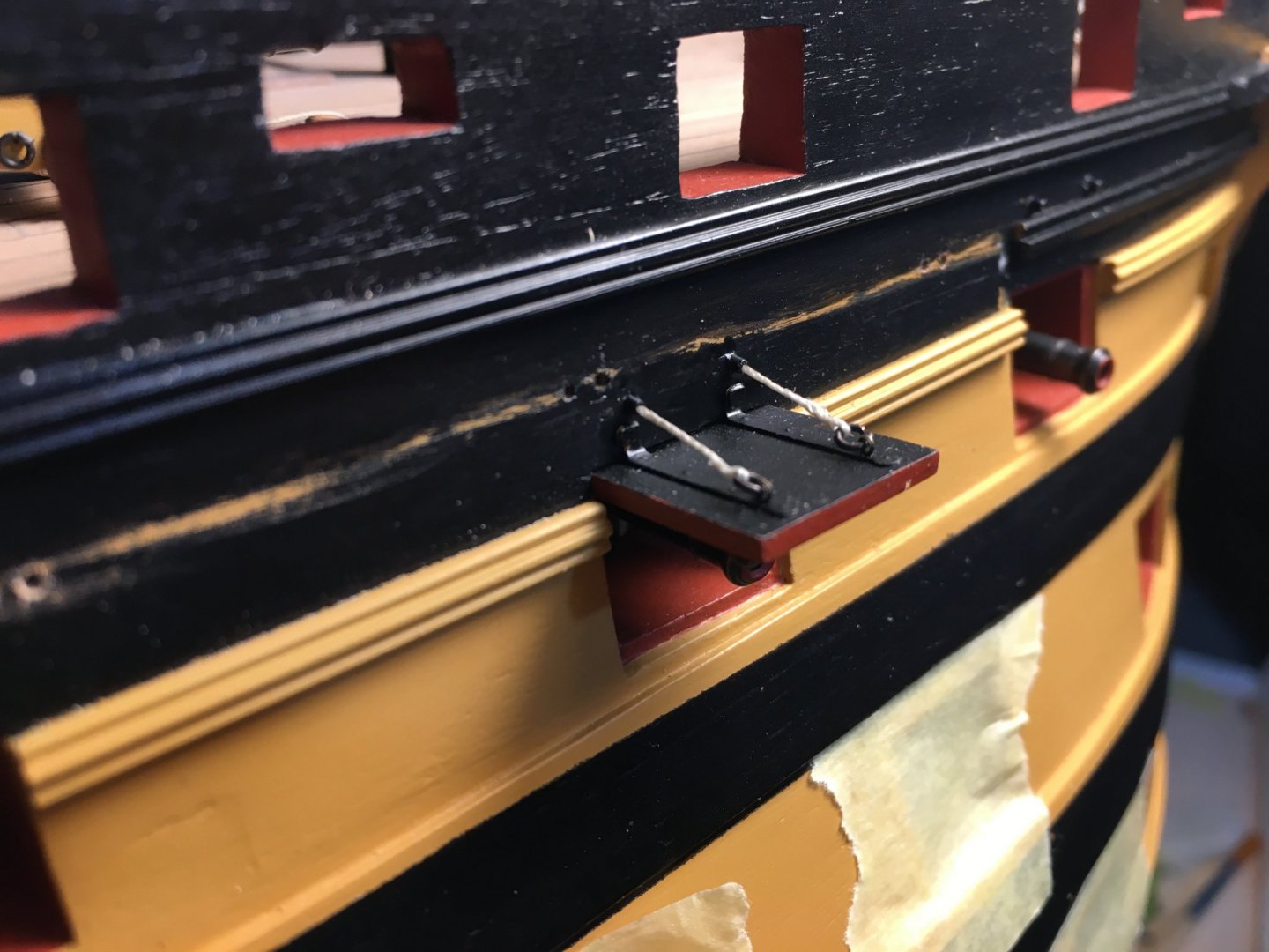
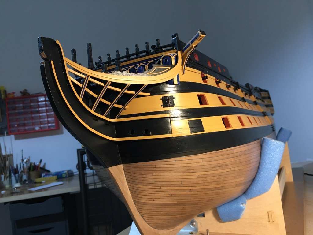
Thank you Heinz, from time to time I visit your build and appreciate your beautiful work. Also thank you everybody for the likes. I added another detail on the gallery. I fitted a strip of wood with a rounded edge just under the railings. I think the finish looks better. The railings are still only dry fitted. I decided to fit the rudder. I want to finish certain work before I finish the stern with the brass railings and the metal decorations. The paint scratches so easily especially from the brass, so prefer to leave the least handling for after I finish the stern. Since the stern in the kit is made up of one piece I grooved the face to show the pieces it is made up of. I filled the grooves with black filler and sanded the faces. For the straps holding the hinges I drilled the already marked holes through and fitted them with small dome head pins. The dome headed pins supplied with the kit seemed a bit too large for this job. I managed to find smaller once from CMB. I blackened the brass strips and the pins. Pins were cut very short, long enough for a very short part of it to go into the hull. Small holes were made in the hull in line with the brass straps as I went along, a tiny spot of super glue is applied to the front of the pin and pushed through the brass strip into the hull. You do not have to glue the brass strips to the hull, the pins will hold them in place. One thing which was bothering me was the shape of the brass fire buckets supplied with the kit. As you can see in the following photo it is very plain and it doesn't even look like a bucket. In the instruction manual it tells you to just drill two holes on the sides and tie on a handle with thread. I added some detail to them. From the left extra pieces of brass with the supplied photo etching sheets I cut small narrow pieces and shaped them in a ring to fit the top edge of the bucket. Drilled a hole the same diameter of the bucket in a piece of MDF and left a bit of the bucket protruding out of the MDF. Put the brass ring around the edge. This kept the ring exactly in place to enable me to solder it. Soldered it. Finished them with a file. Drilled two small holes on the edge and fitted two very small eyelets to the rim for the handle. The eyelets are like the once supplied with the kit, of which I had to buy extra from CMB. Looks more like a bucket now. Robert


- 527 replies
-
- 11
-
-
- caldercraft
- victory
- (and 1 more)
-
fire buckets
Robert29 replied to mfrazier's topic in Discussion for a Ship's Deck Furniture, Guns, boats and other Fittings
mfrazier, I am currently building the caldercraft HMS Victory. The dimensions for the fire buckets supplied with the kit are: Height: 5mm Base diameter: 2.5mm Top diameter: 3mm Robert -
Thank you very much for the encouraging comments and likes. Bill feel free to use whatever is in my log. As much as I have learned from this forum sourcing ideas and hints from other builders it is my pleasure to know that my work is of some help to others. Robert
-
Really nice work Jason. Very detailed and great images of your work. Robert
- 800 replies
-
- 2
-
-
- snake
- caldercraft
- (and 1 more)
-
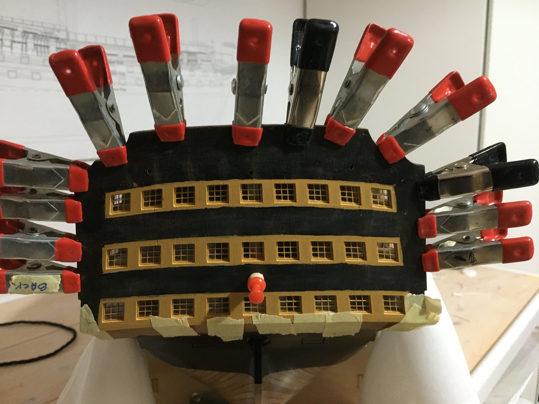
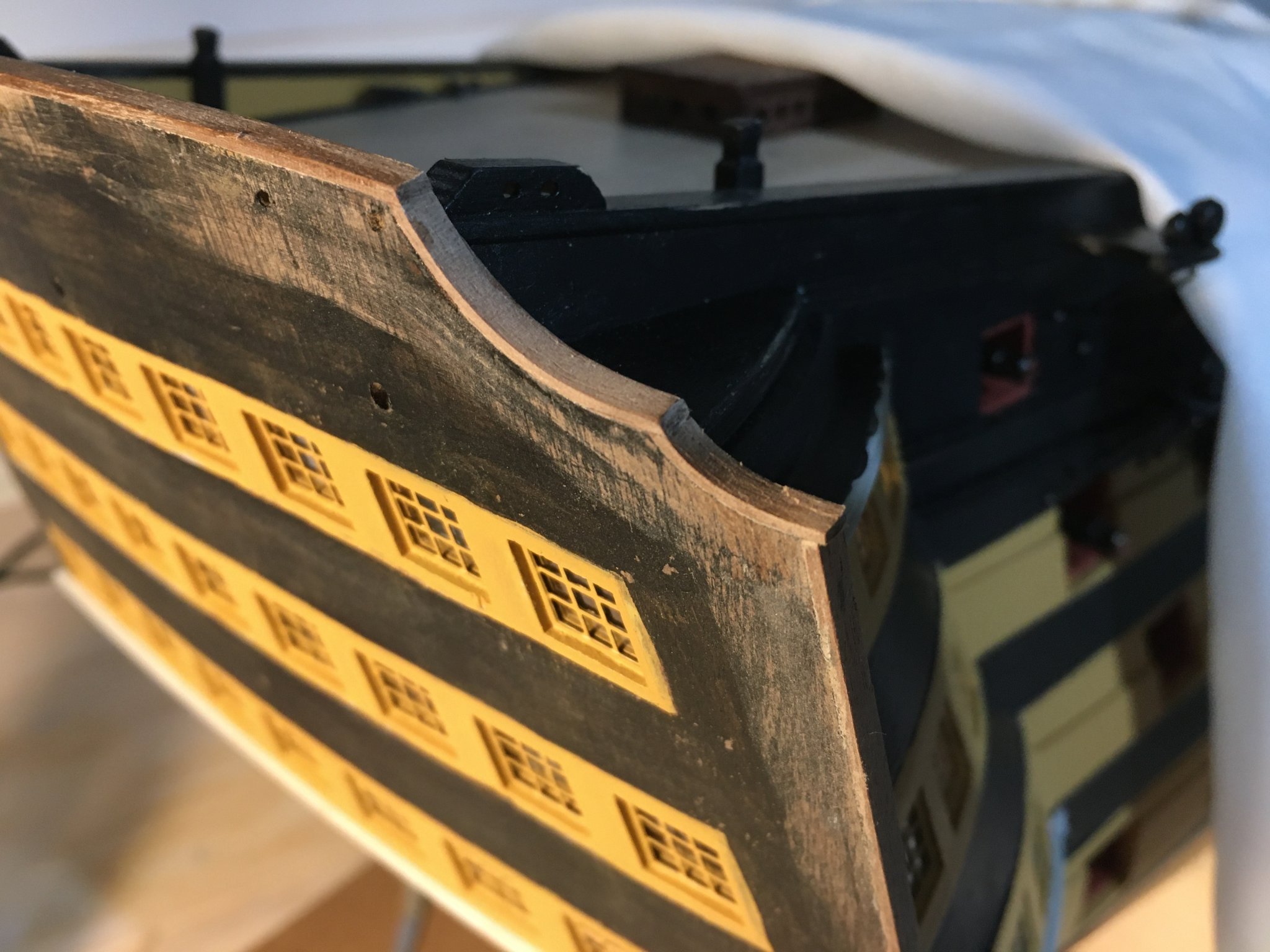
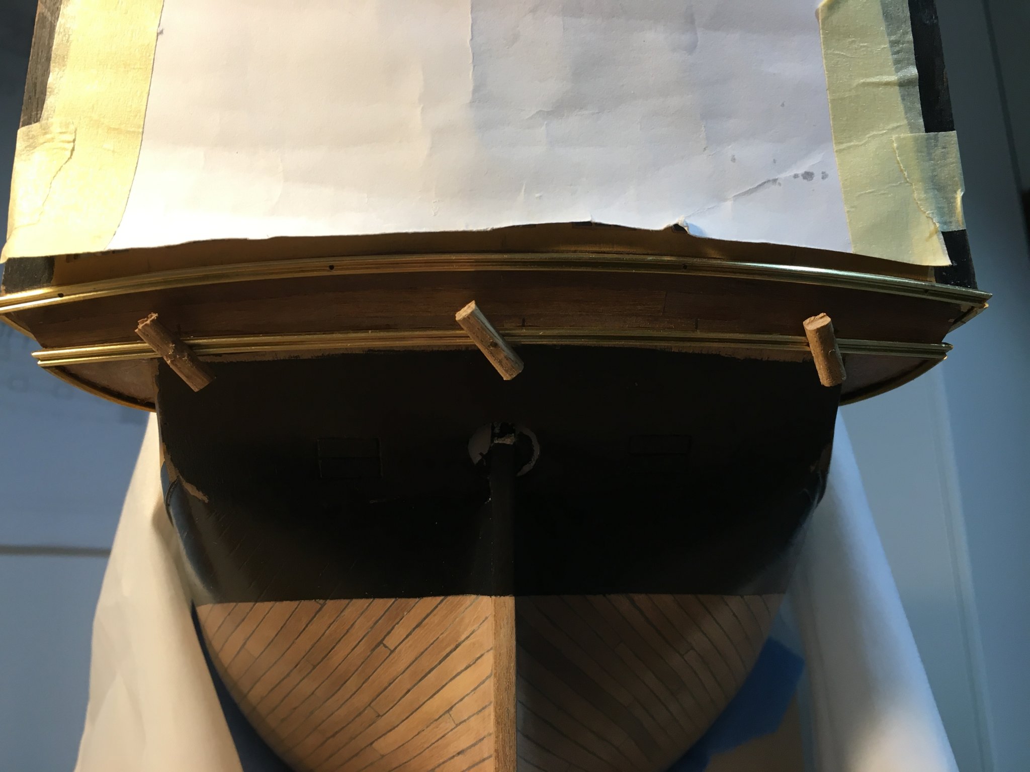
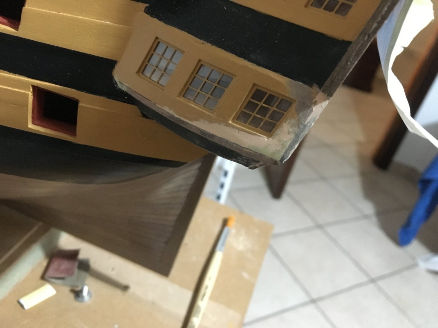
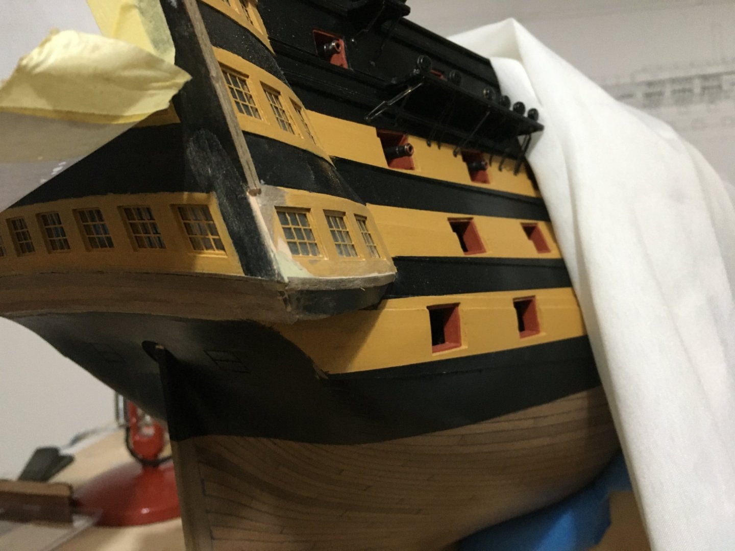
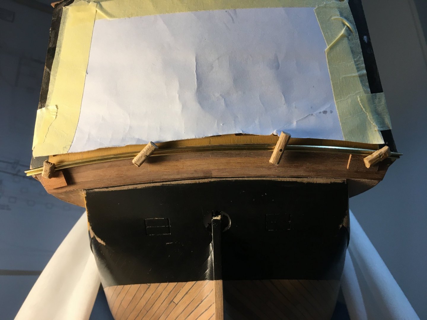
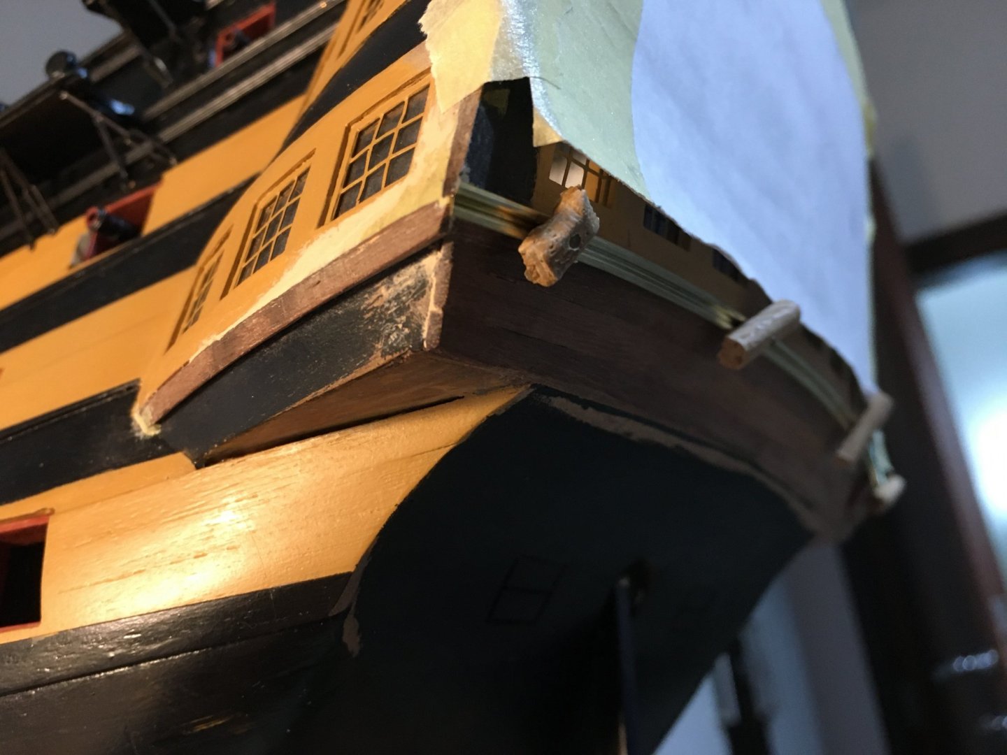
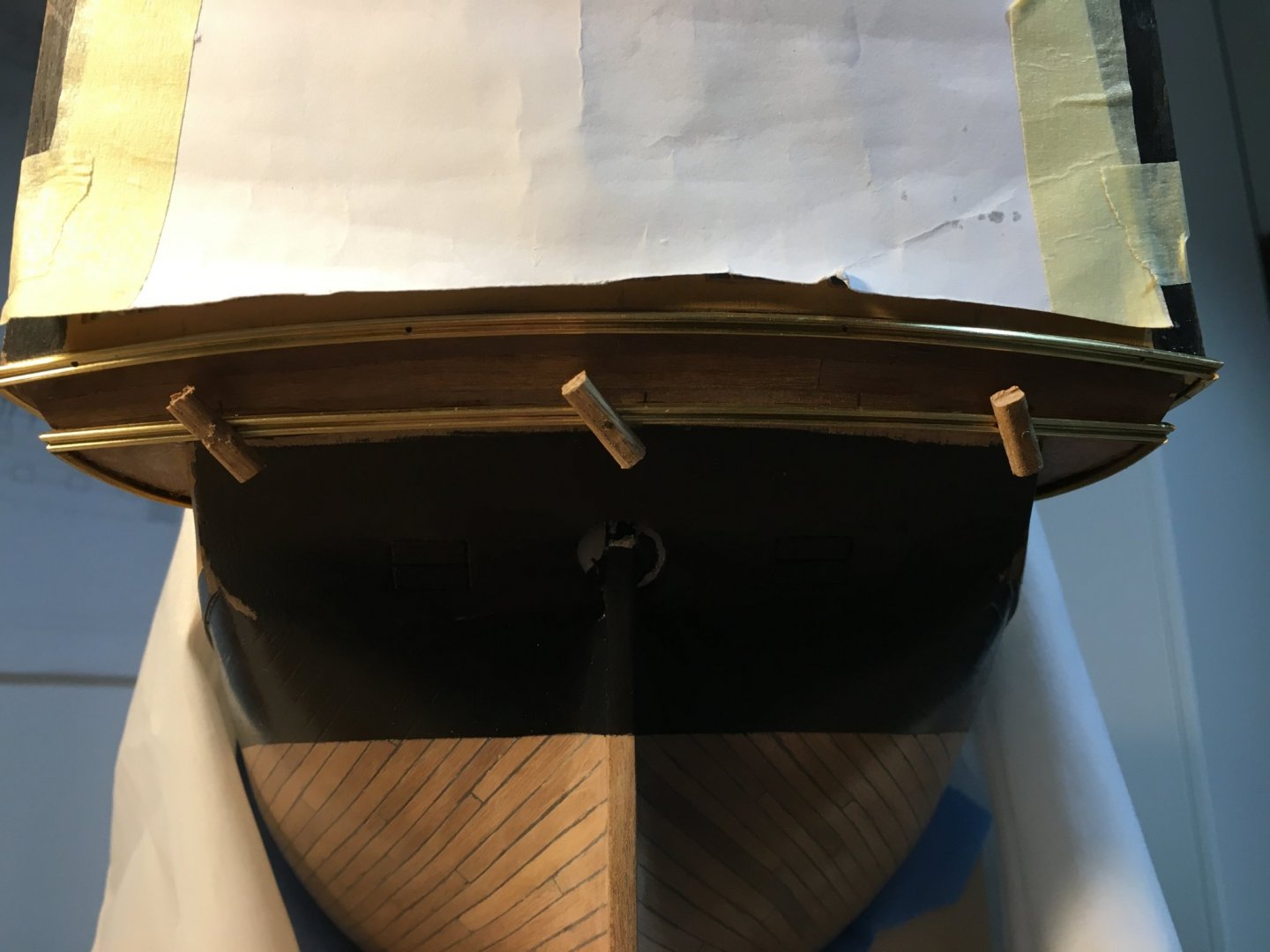
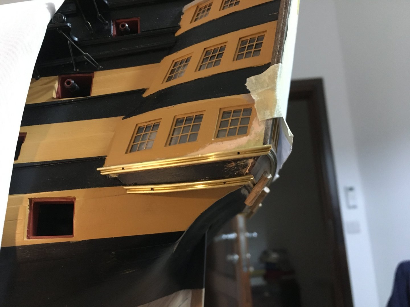
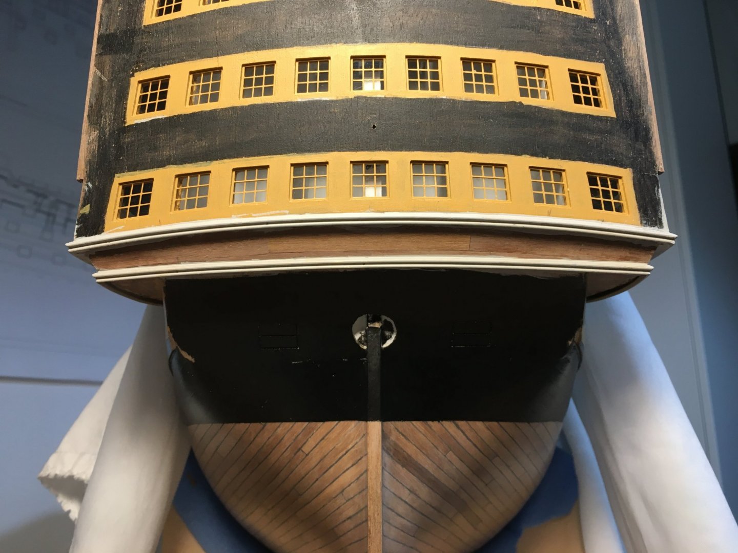
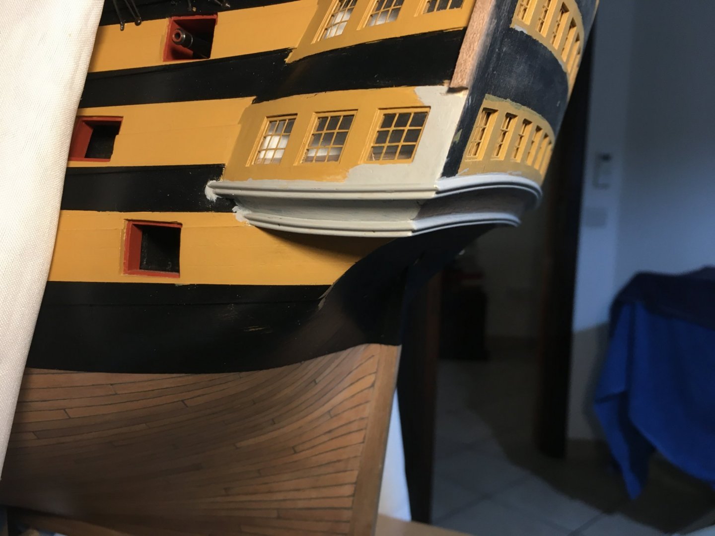
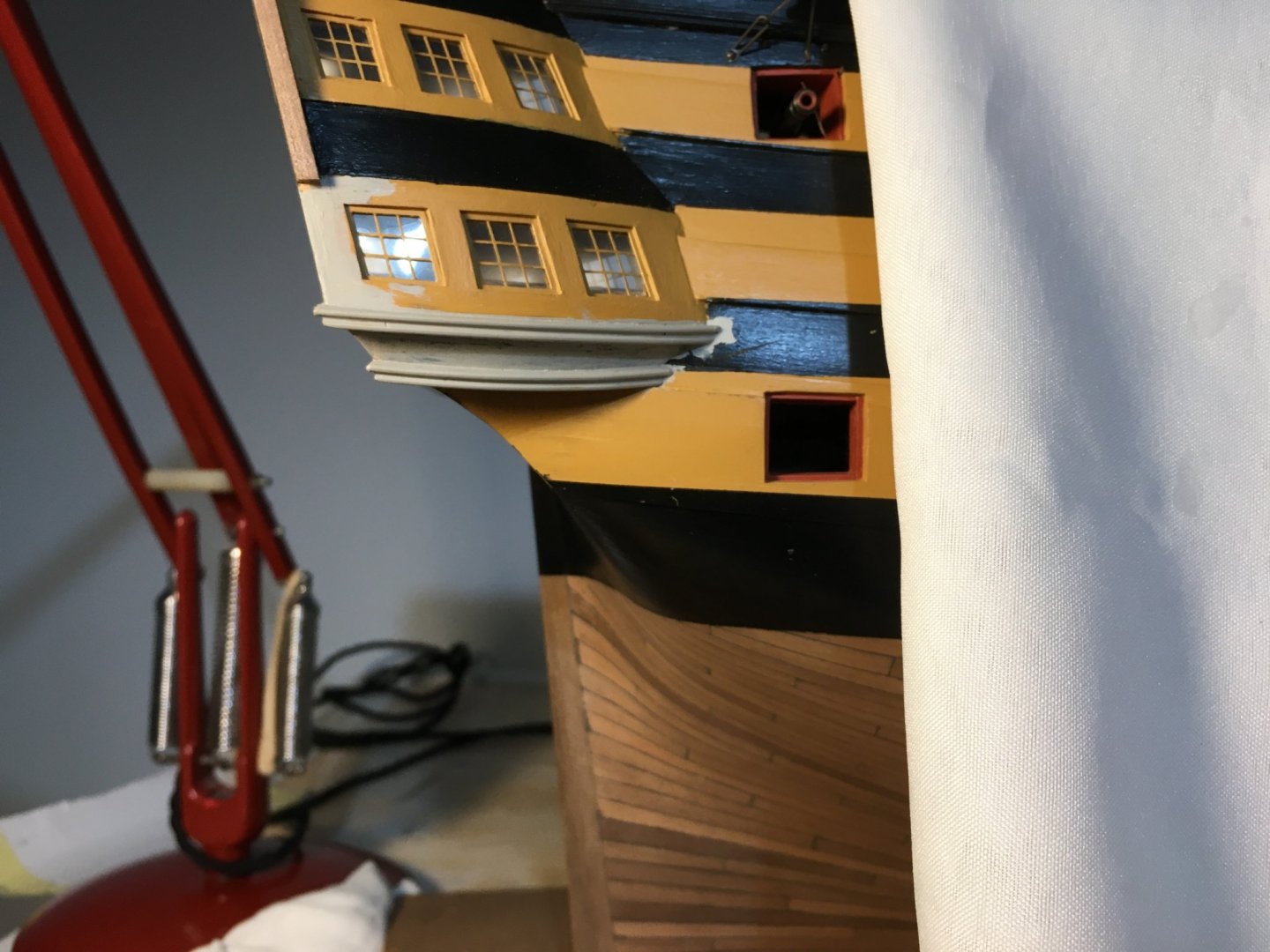
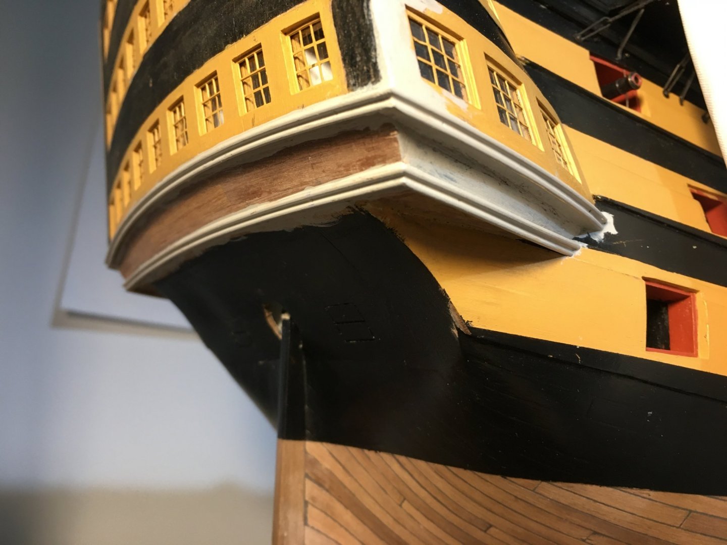
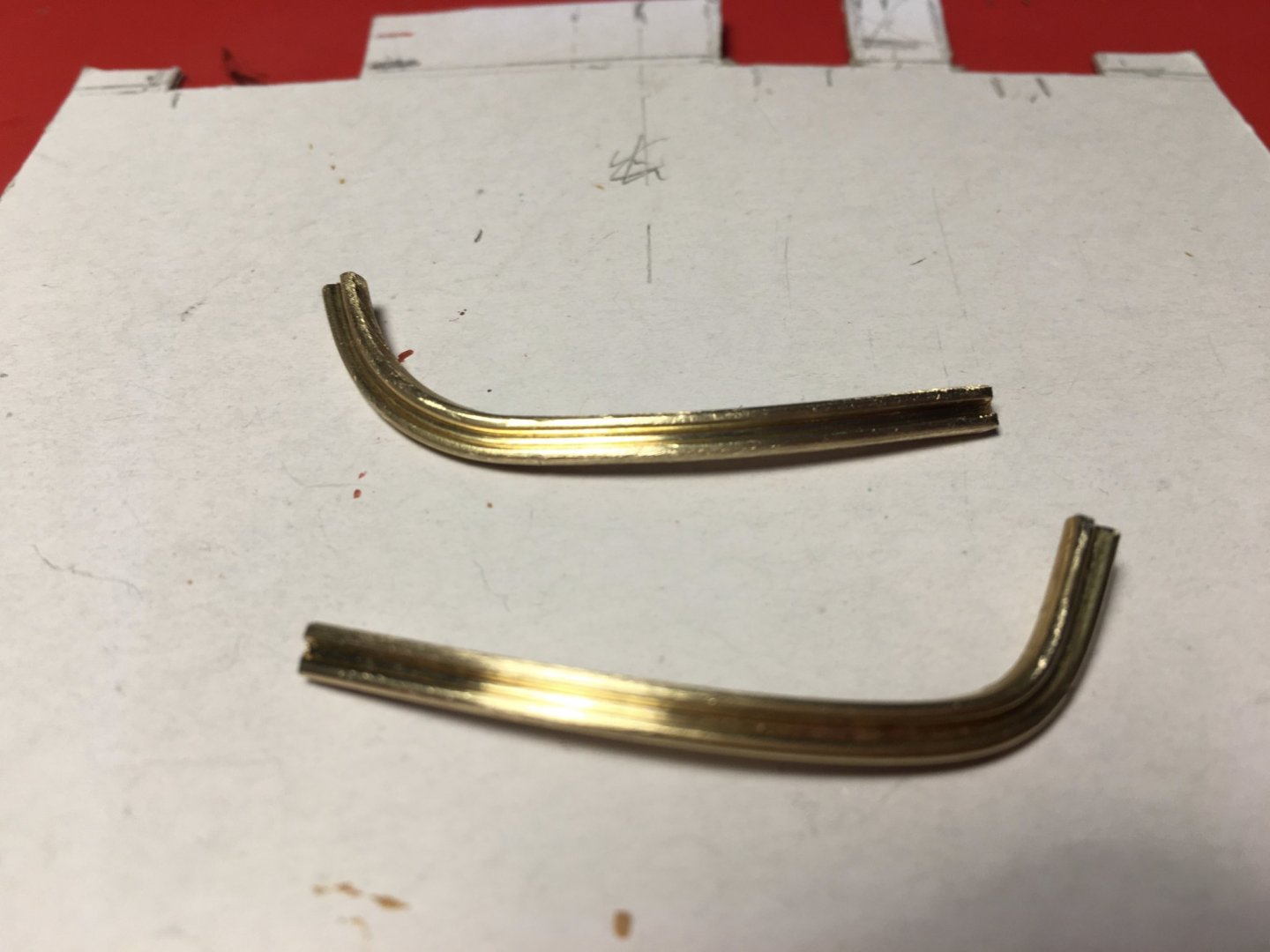
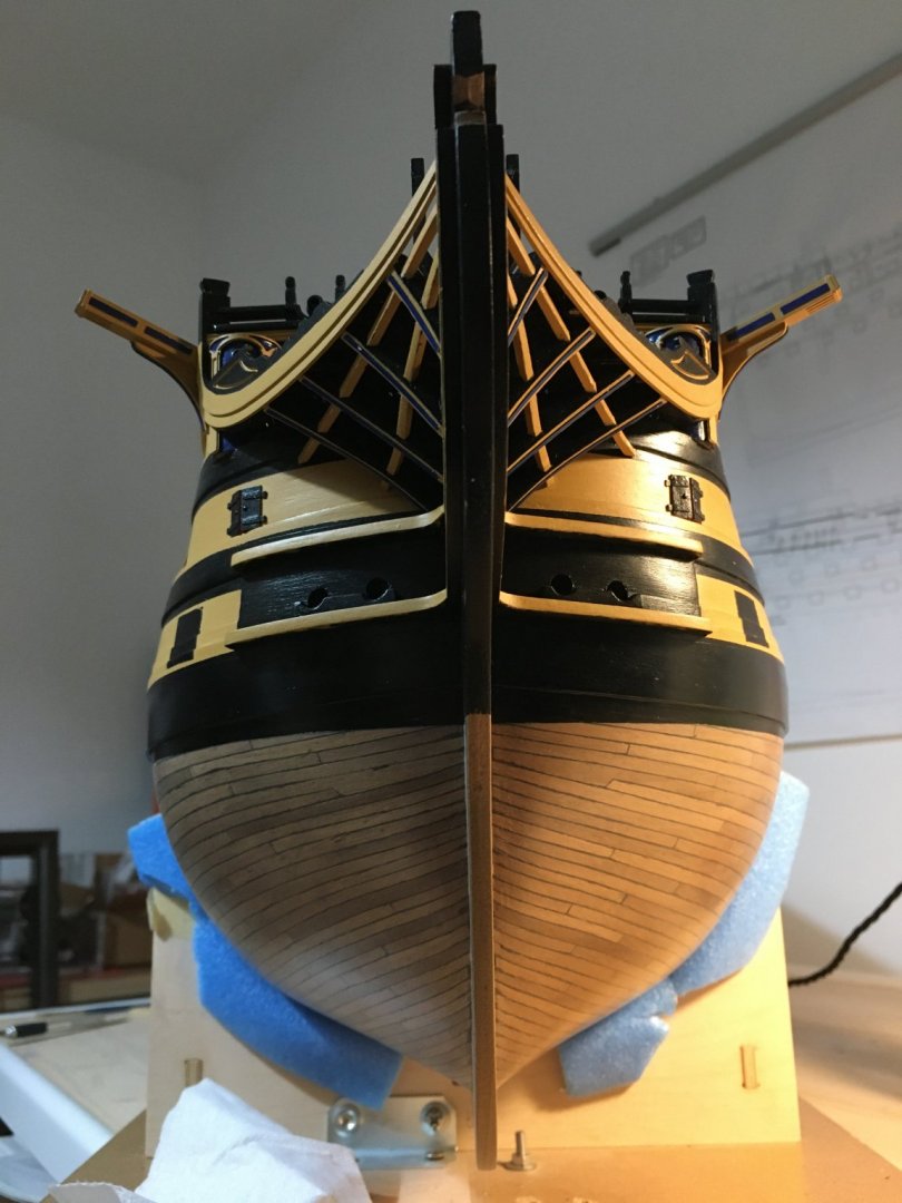
Richard, thank you for your nice comments, I have already marked the deck treenails, butt ends only. With the lanterns put aside to be fitted at a much later stage, probably for the very last as otherwise I am sure I would nock them down multiple times whilst doing the rigging, I fitted the outer stern fascia in place. Before I fitted it I painted the window frames, glued transparent plastic strips to the inner fascia, in front of the windows to represent the glass panes and gave it a coat of paint, just to know were the outlines of the two different colours should be. I will finish the paint with more coats when in place as obviously there is going to be a lot of rough handling and sanding to fit the brass profiles. The bottom edge of the fascia had too much of an overhang on the pattern beneath it, so I decided to plank the pattern to bring it in line with the stern fascia. To get a good fit of the brass profiles and to match the corners where they meet mitered at the stern fascia and the galleries needed quite some work. It is imperative for the profiles to be fitted nicely and as accurate as possible. Being at the edges, any imperfections will show. Since I had added an extra 0.5mm skin on the galleries to create the window depths, I had to add a strip of wood underneath to fix the brass profile on. Also had to do some sanding and filling to the edge of the lower gallery where it meets the fascia. to bring it exactly in line with the stern fascia. I couldn't just sand the edge of the fascia as otherwise I will loose the symmetry of the fascia were the scrolls are to be fitted. Fitted the edge capping for the fascia. If you notice I left the edge of the outer curve overhanging a bit as I might glue thin strips of styrene on the outer edge of the fascia. If not I will sand flash. It was quiet time consuming to get the brass profiles the right shape as they had to be bent flat wise and edge wise at the same time. Since there is no place to put any clips to hold the brass profiles whilst glue is drying I thought the best method to keep them in place was to drill small holes in the profiles and keep them in place with nails. I did not want to use super glue as I wanted to have time to line them exactly in place and also for better adhesion I used epoxy glue. Brass profiles mitred corners filed nicely together, finished with some filler and given a coat of metal primer. Robert


- 527 replies
-
- 14
-
-
- caldercraft
- victory
- (and 1 more)
-
Hi Graham, good to see your progress on the Victory. As usual very accurate work. The belfrey is fantastic. Robert
-
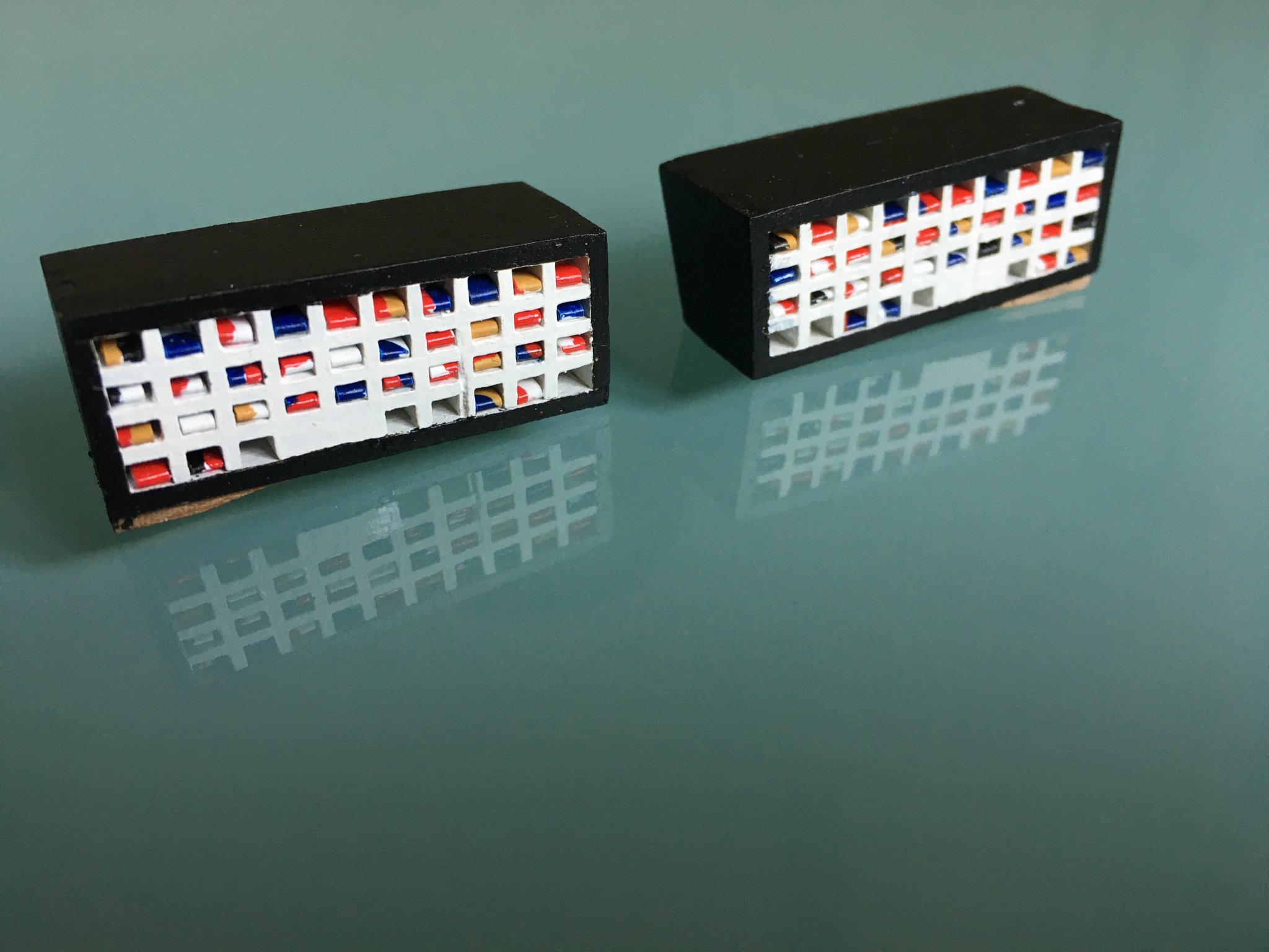
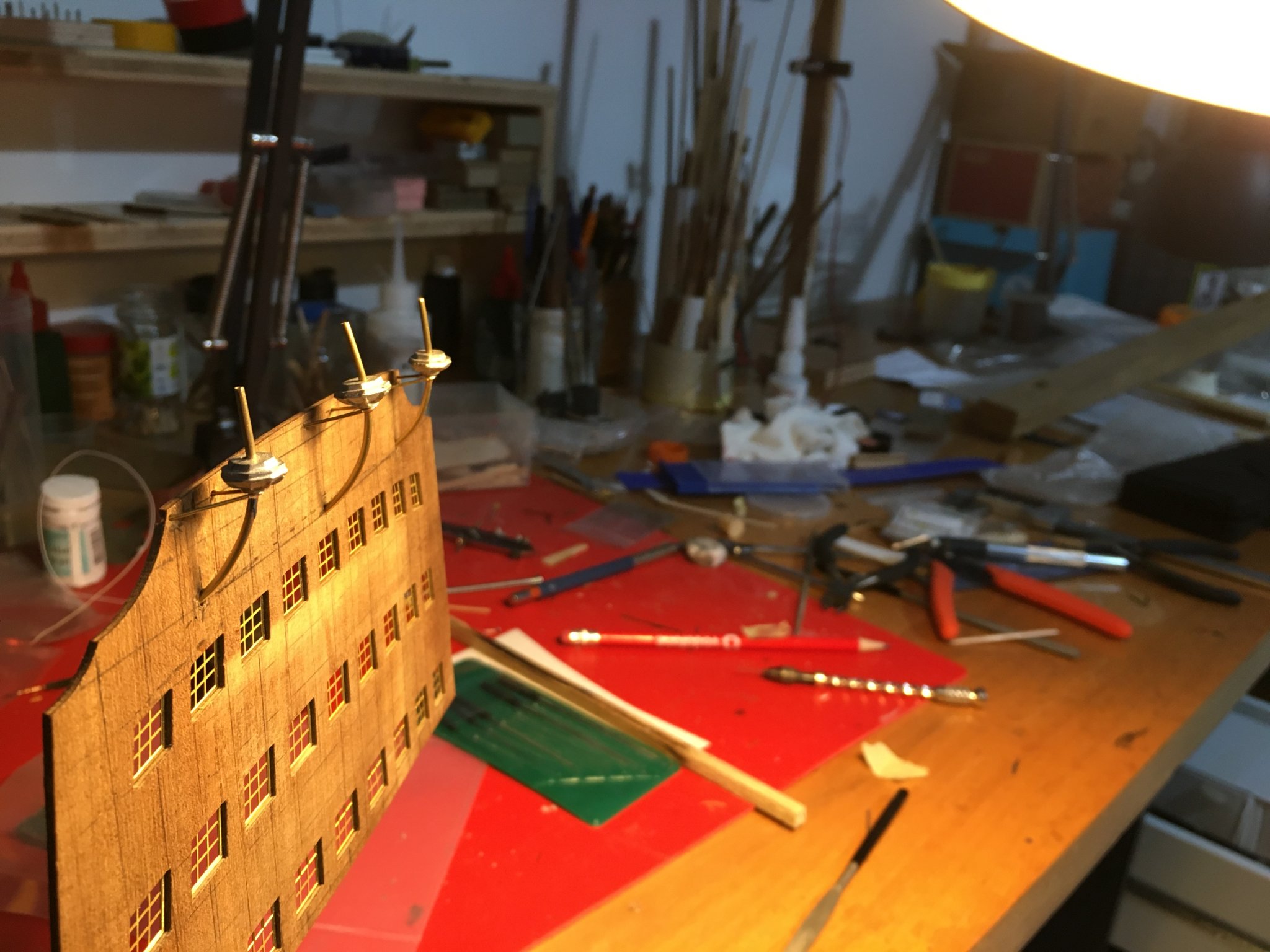
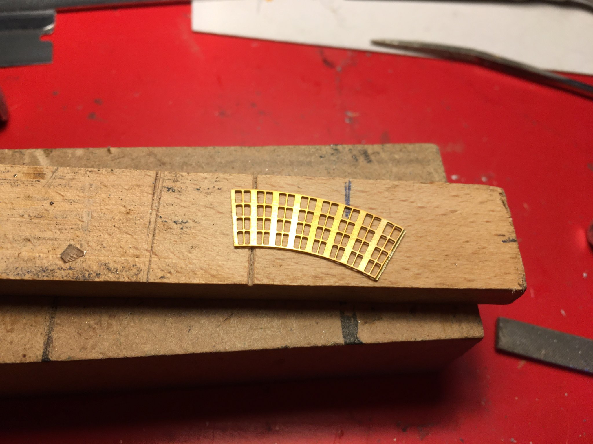
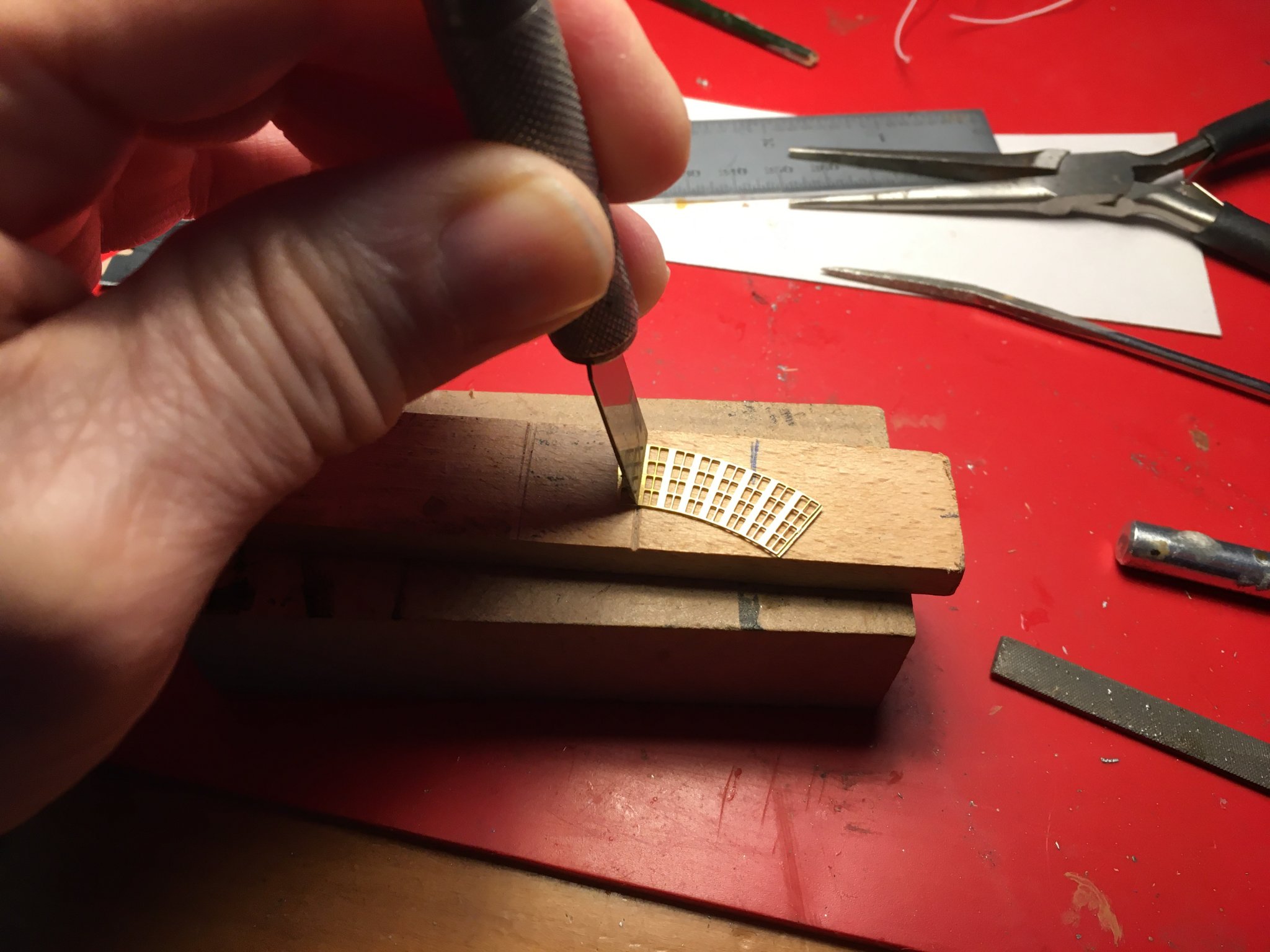
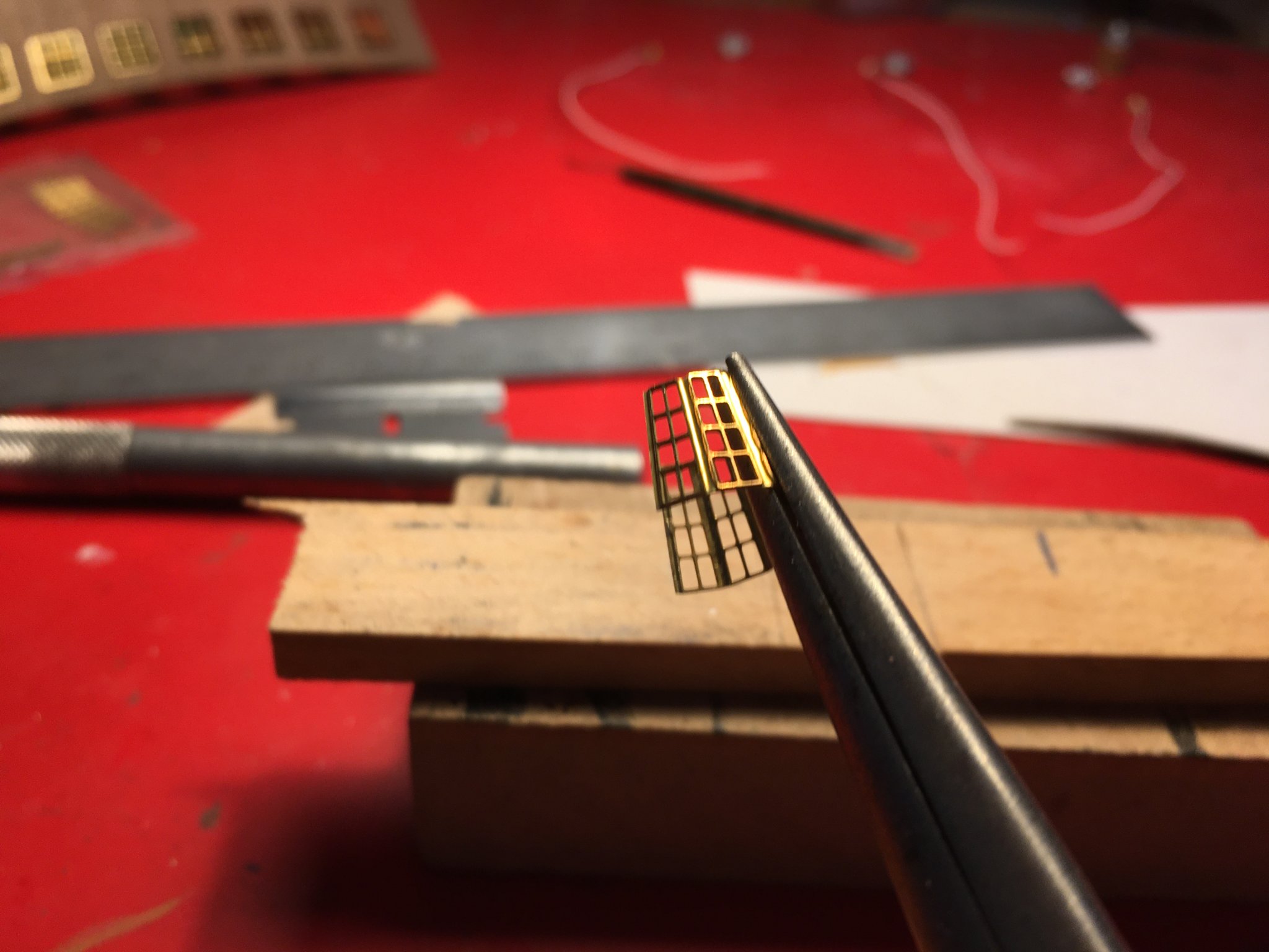
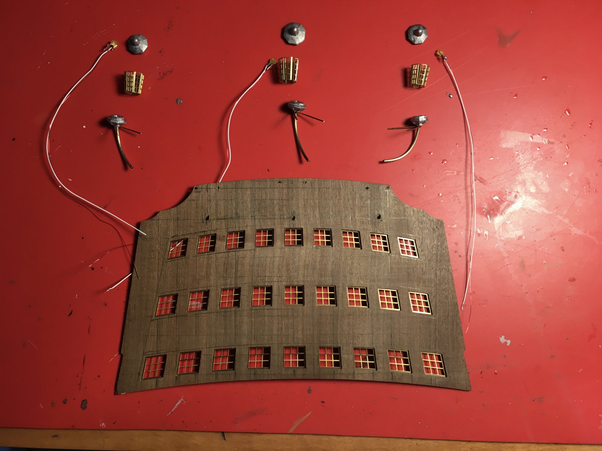
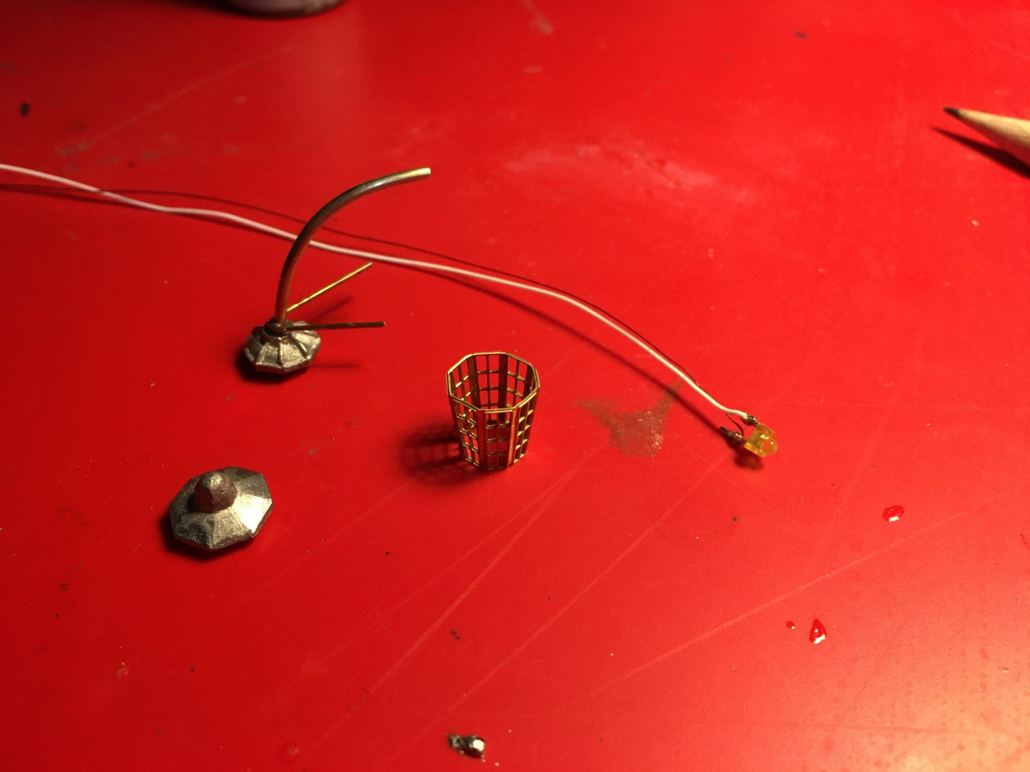
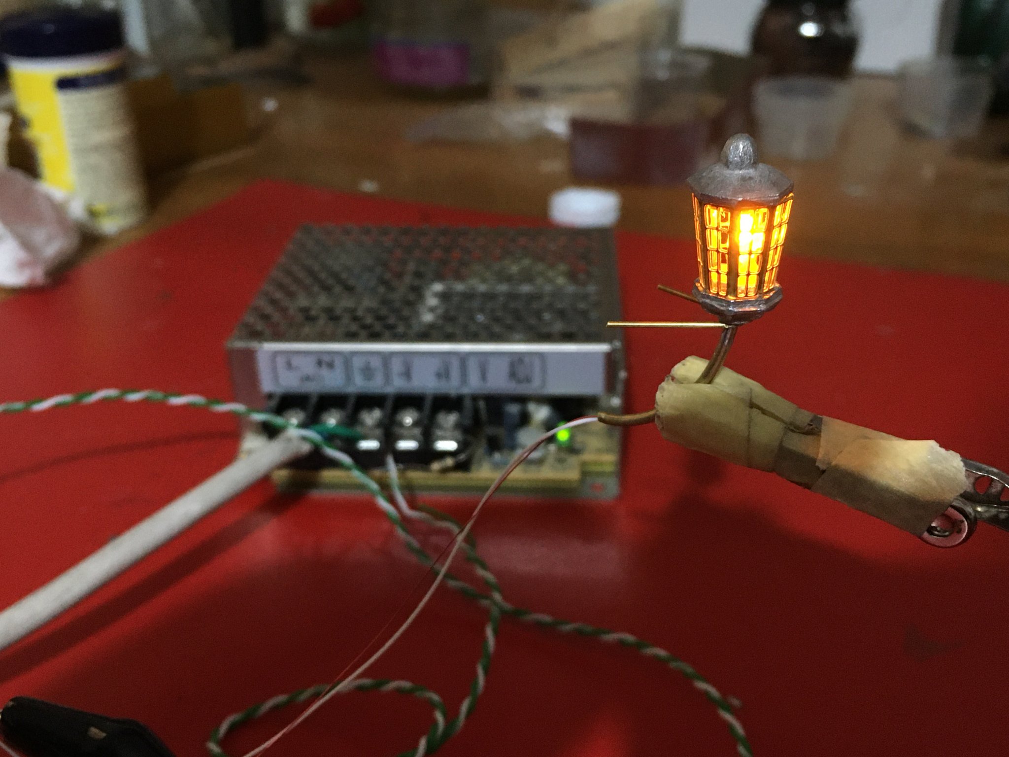
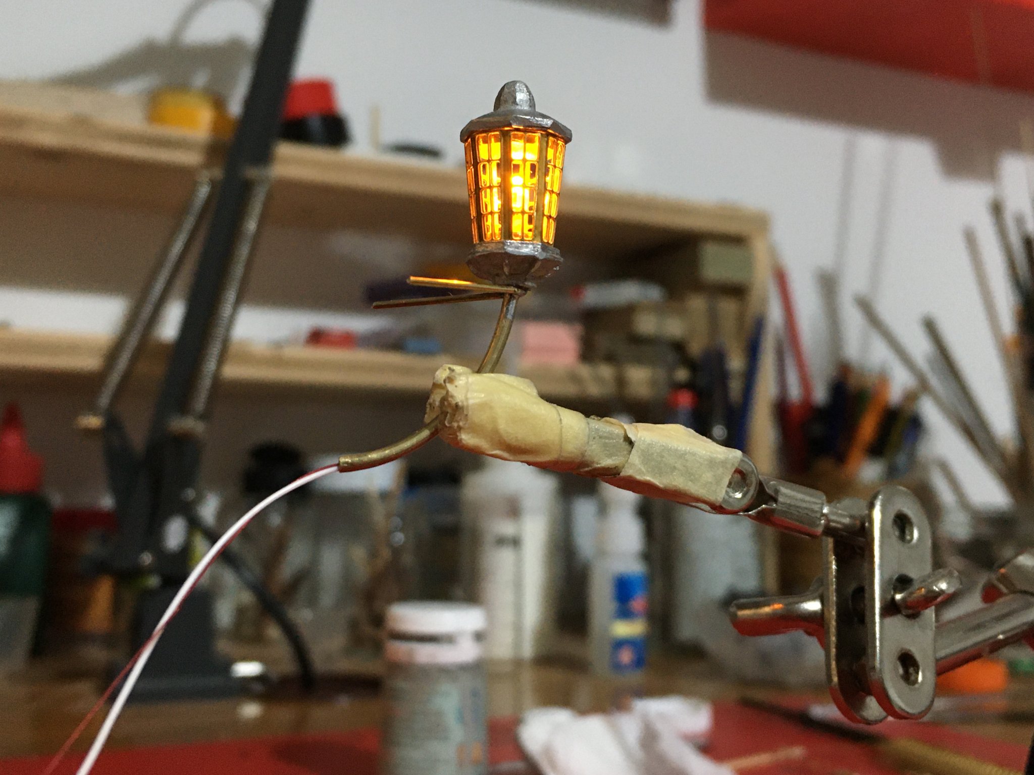
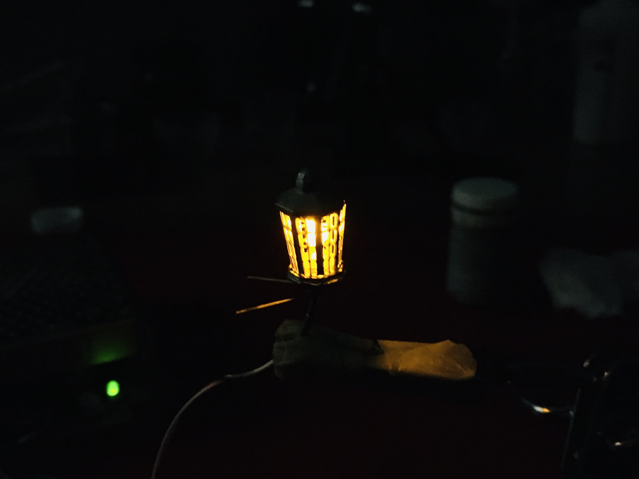
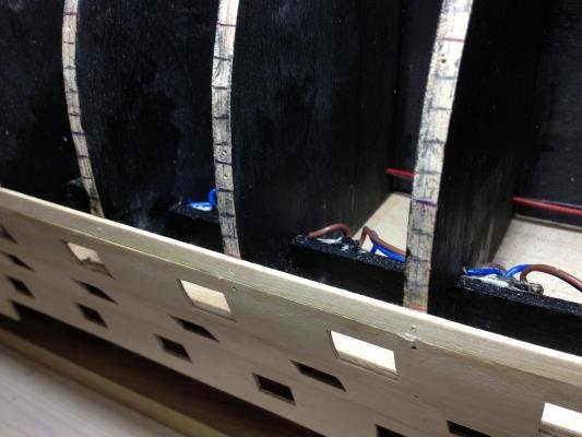
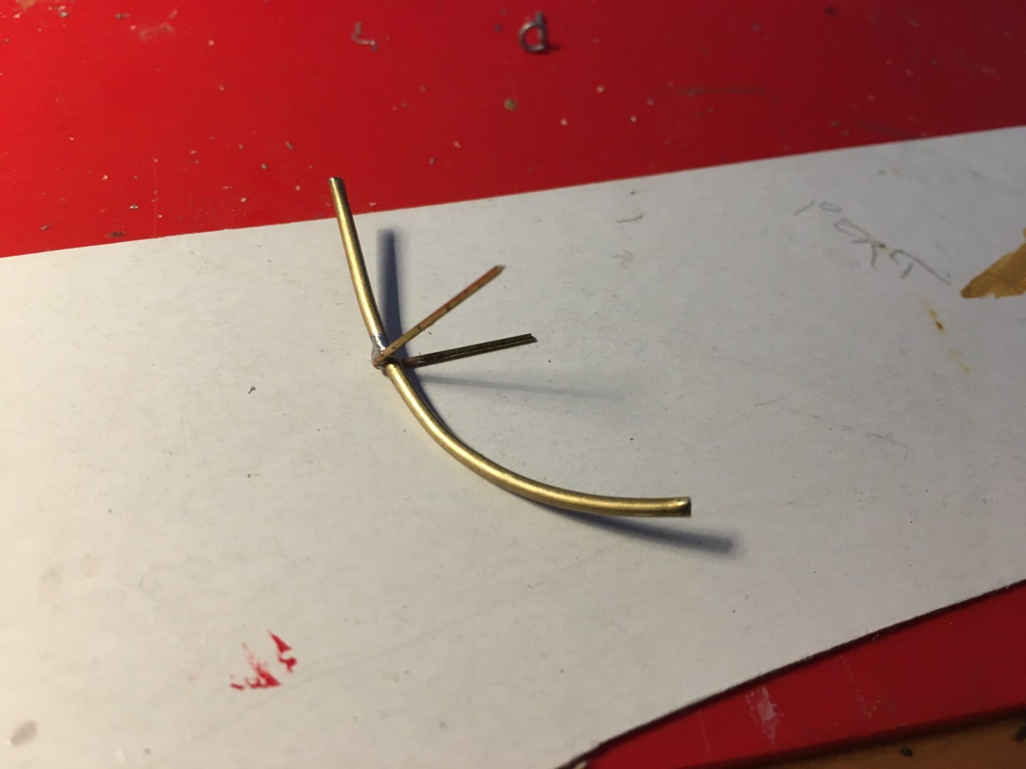
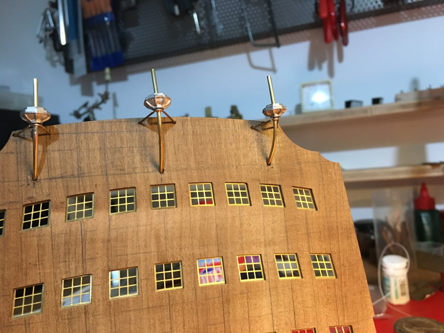
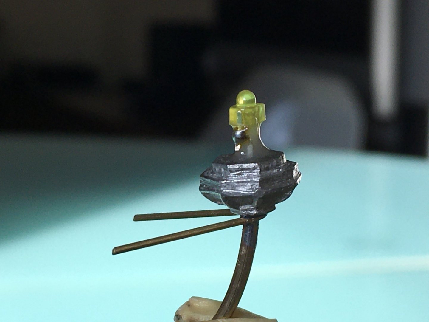
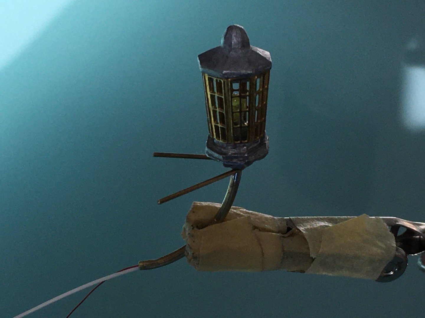
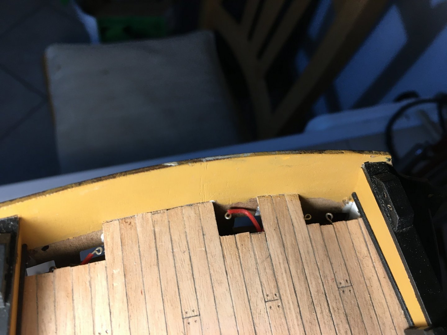
Kevin, thank you, from time to time I visit your magnificent build for the Victory to steal some ideas. Some more progress: Added some more detail to the flag lockers. I added the flags folded in the lockers I made from thin strips of styrene, folded in three layers and painted different colours. I decided to start work on the stern fascia. As I had noticed on some Victory builds I fitted the window frames from the back of the fascia. Since I am putting lights in the three stern lanterns the positioning of them on the stern fascia is quite critical to make sure the wiring entering the fascia are in the right position to connect to the prepared inside wiring. Decided it would be much easier to prepare the lanterns now, find the exact positions on the fascia and prepare the holes with the fascia still in my hands, otherwise if I leave them for after finishing the fascia I am sure it will be more difficult and I would damage the paintwork, especially on the brass fittings. I made the frames holding the lanterns from 1.5mm brass tubes through which the wiring is to pass. Soldered the supporting arms made from 0.7mm brass rods supplied with the kit. Calculated the positions of the entry holes of the brass tube and the rods into the fascia. As you can see I drew a grid on the fascia which helped me a lot to keep everything symmetrical. I made sure that the entry holes did not interfere with the trophy of arms or any brass mouldings that have to go on the fascia. Only dry fitted for now. Bent the lantern brass etched components to the right shape and soldered where they meet. Soldered the wiring to the small LED's and glued the base of the lanterns to the brass tube with epoxy glue. I also made sure all the lantern components fitted each other. After passing the wiring through the brass tube I glued the LED to the lantern base with Araldite epoxy glue, which is non conductive. You have to be sure that the glue you use is non conductive otherwise it will short the LED connections. Lantern components just dry fitted. They still have to be painted and transparent plastic used to simulate the lantern glass. Tested each lantern to make sure they are working alright. Now I will put the lanterns aside and carry on with the work on the fascia, knowing that I have the lanterns sorted out and have the exact position for them on the fascia. Robert


- 527 replies
-
- 8
-
-
- caldercraft
- victory
- (and 1 more)
-
Thank you for the likes. Thank you Richard for the comment and for the suggestion. You are right, I am sure the thread will be caught in the gunport lids. So probably I will get the lids ready but will fit in place after the rigging. Mort, thanks for the nice comment. Yes, I ordered the small eyelets from CMB. They are made by Caldercraft (Brass Etched Eyelets - O/A diam: 1.3mm, O/A L: 7mm, Hole diam: 0.7mm) and are the same like the once supplied with the kit. The CMB item part number is C83505 and they come in a packet of 250 pieces. Price is £5.24 per packet plus postage. Robert
-
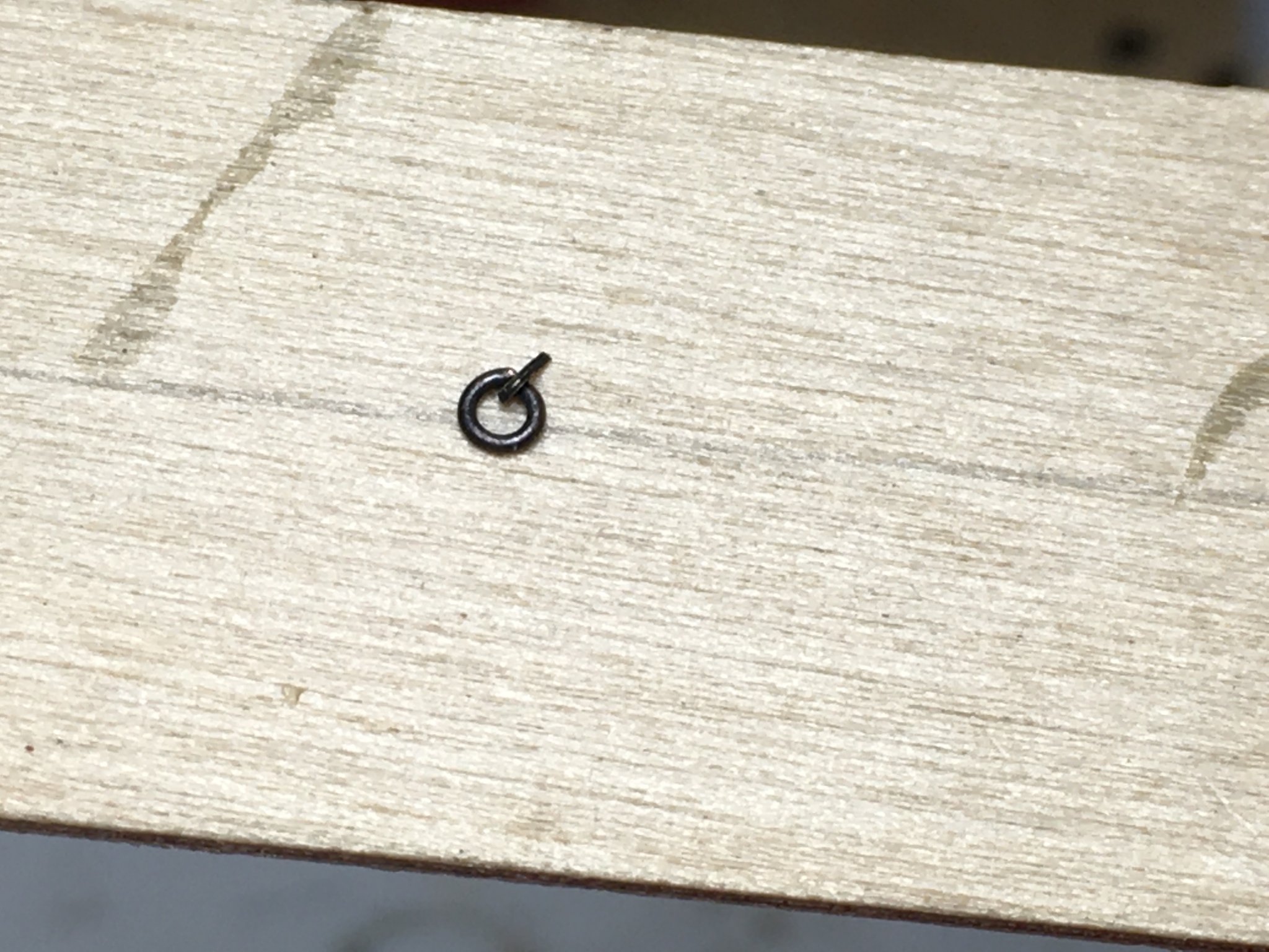
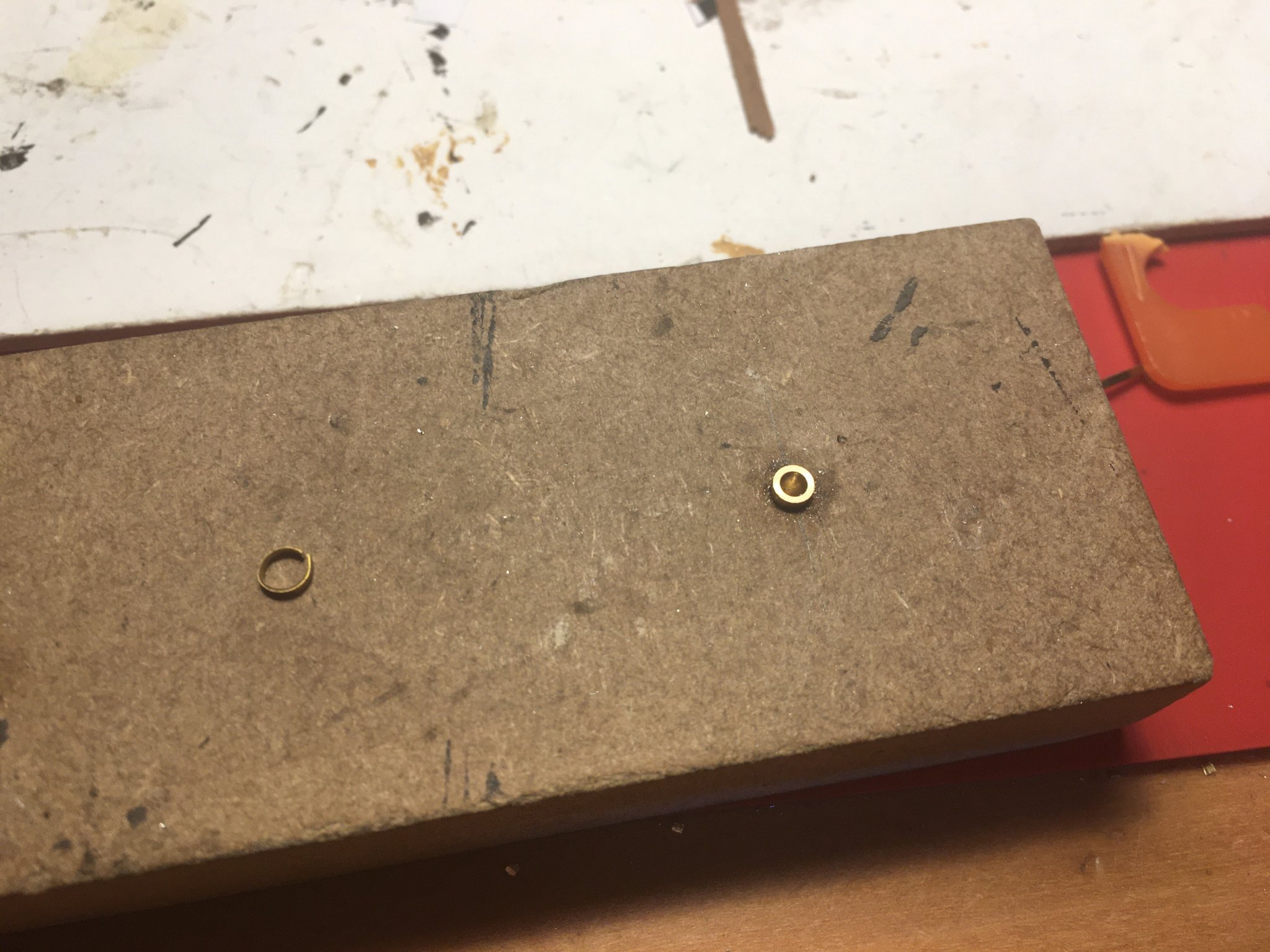
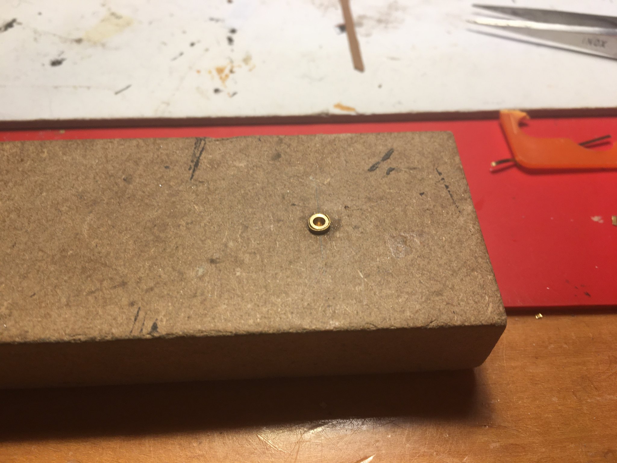
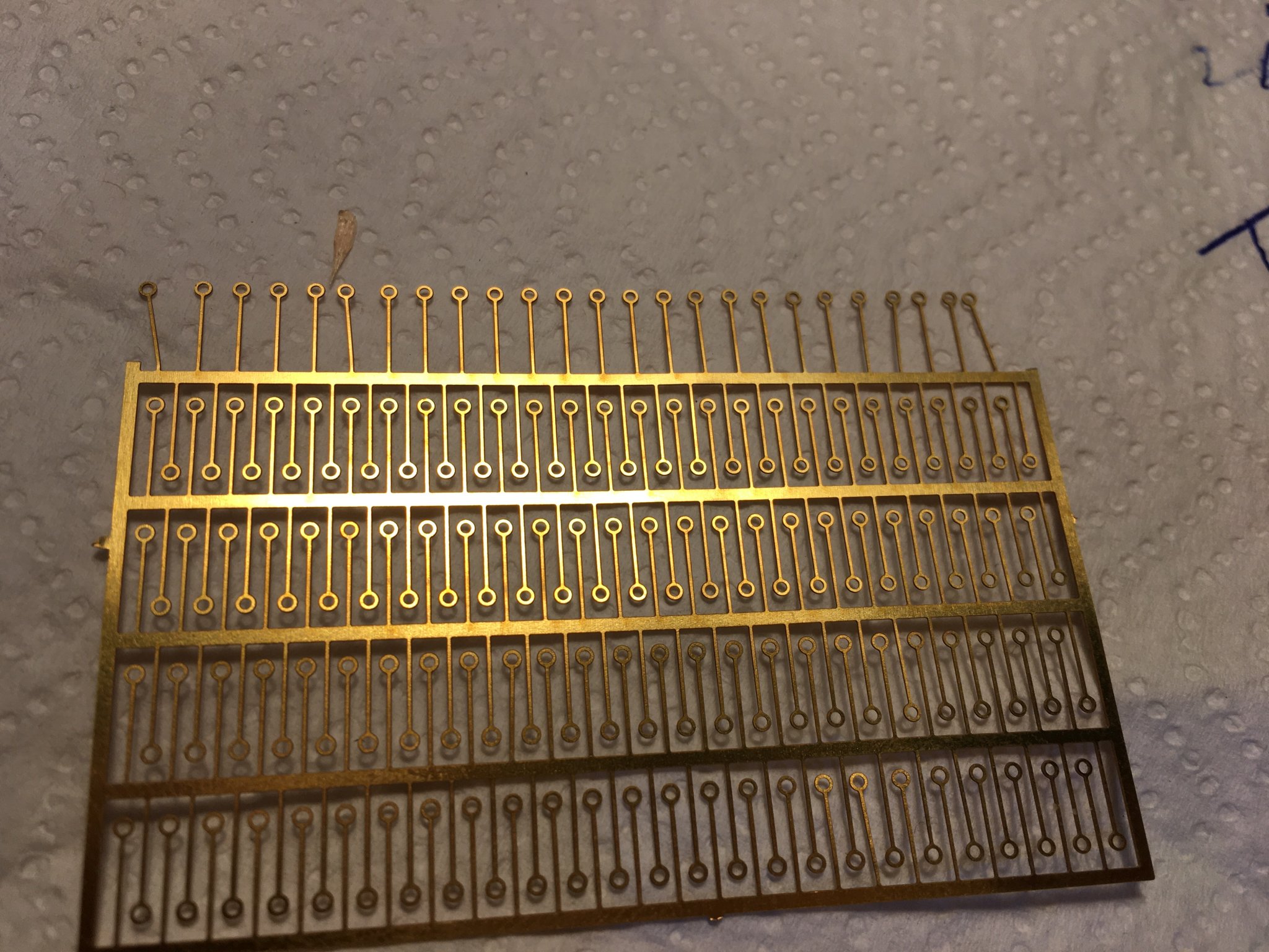
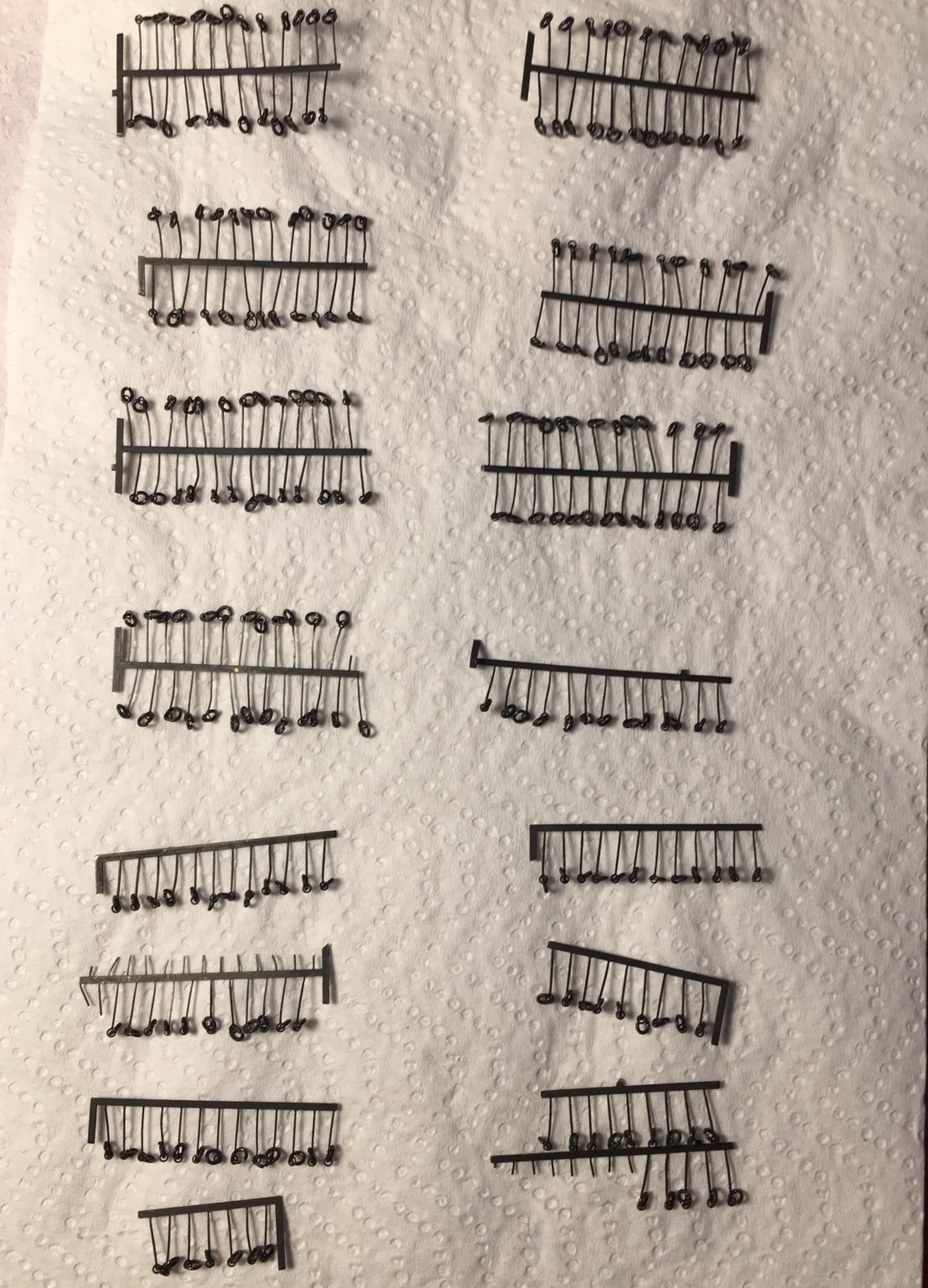
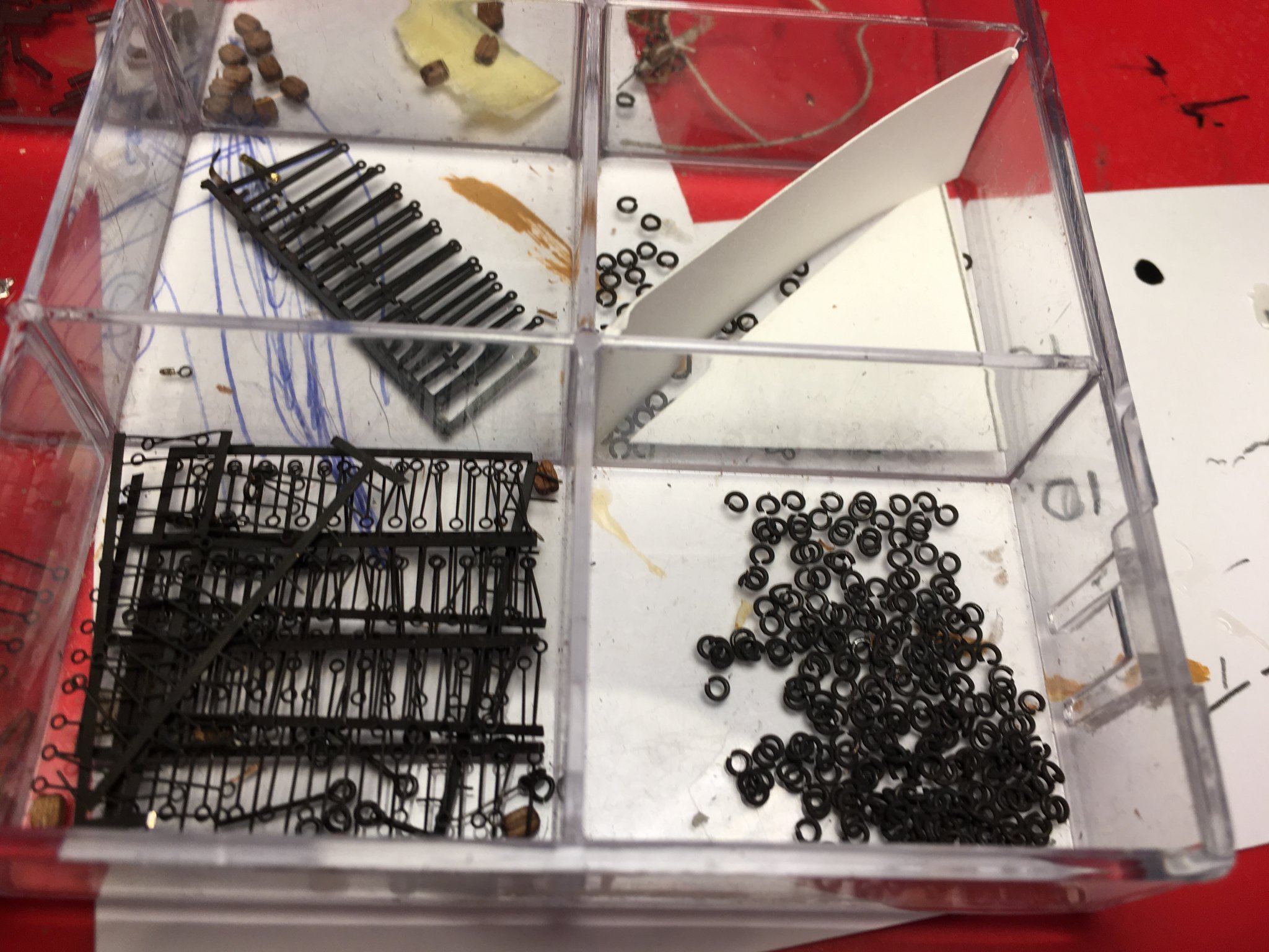
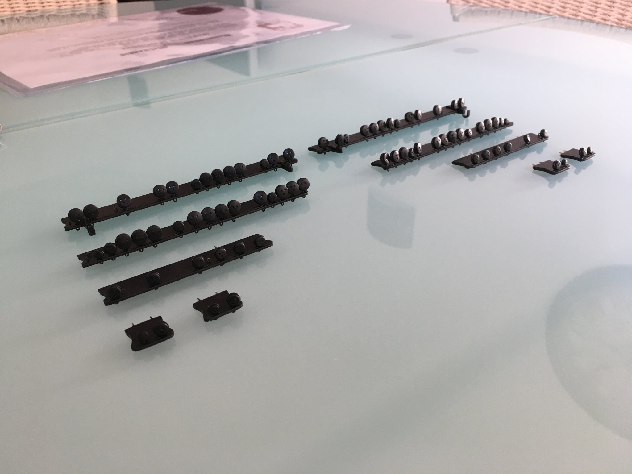
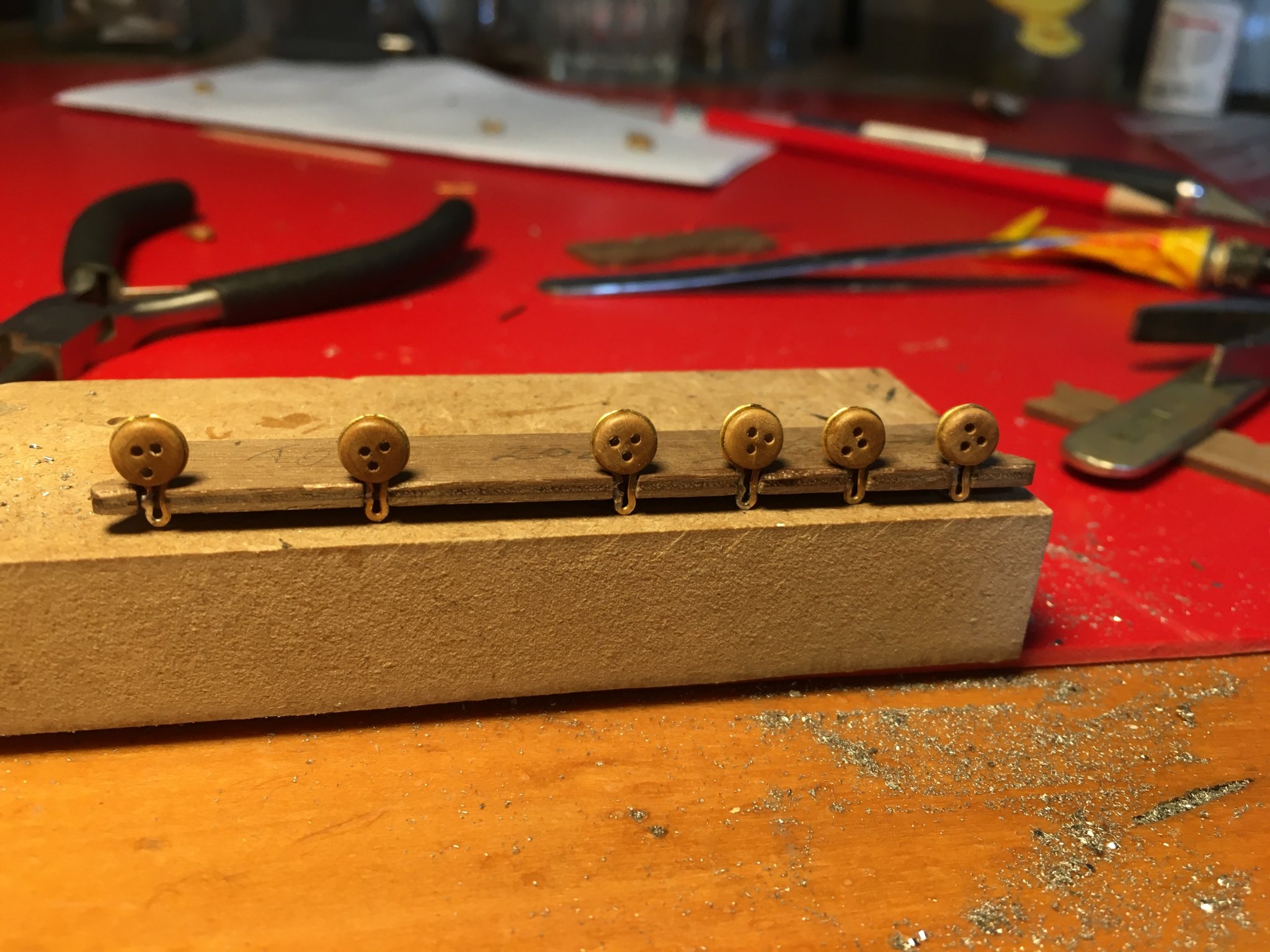
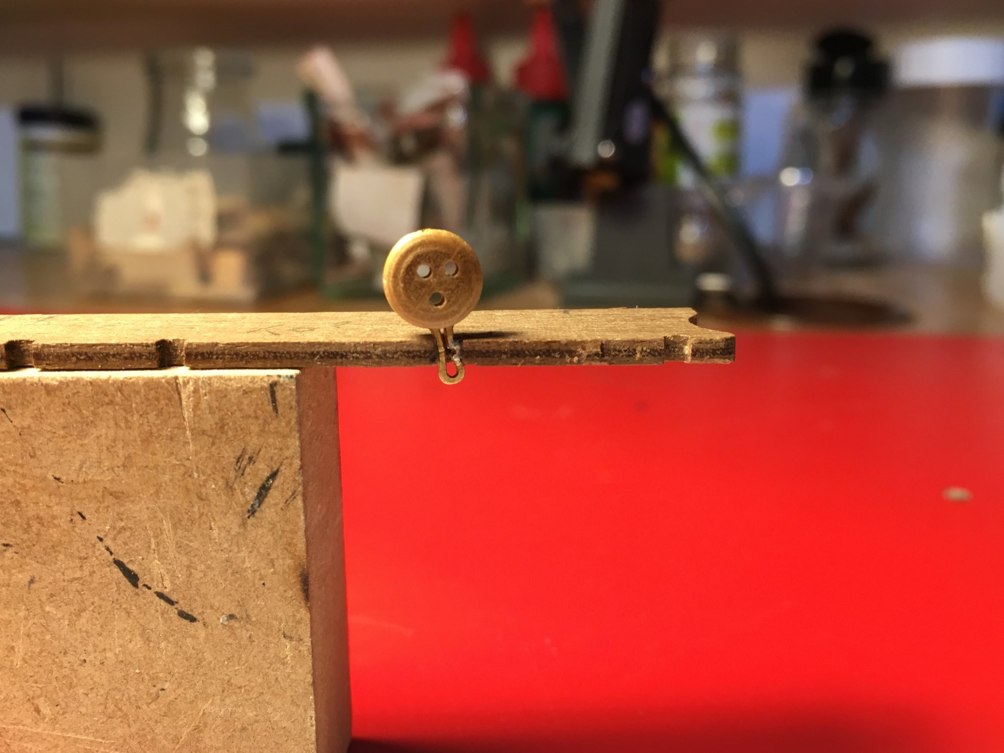
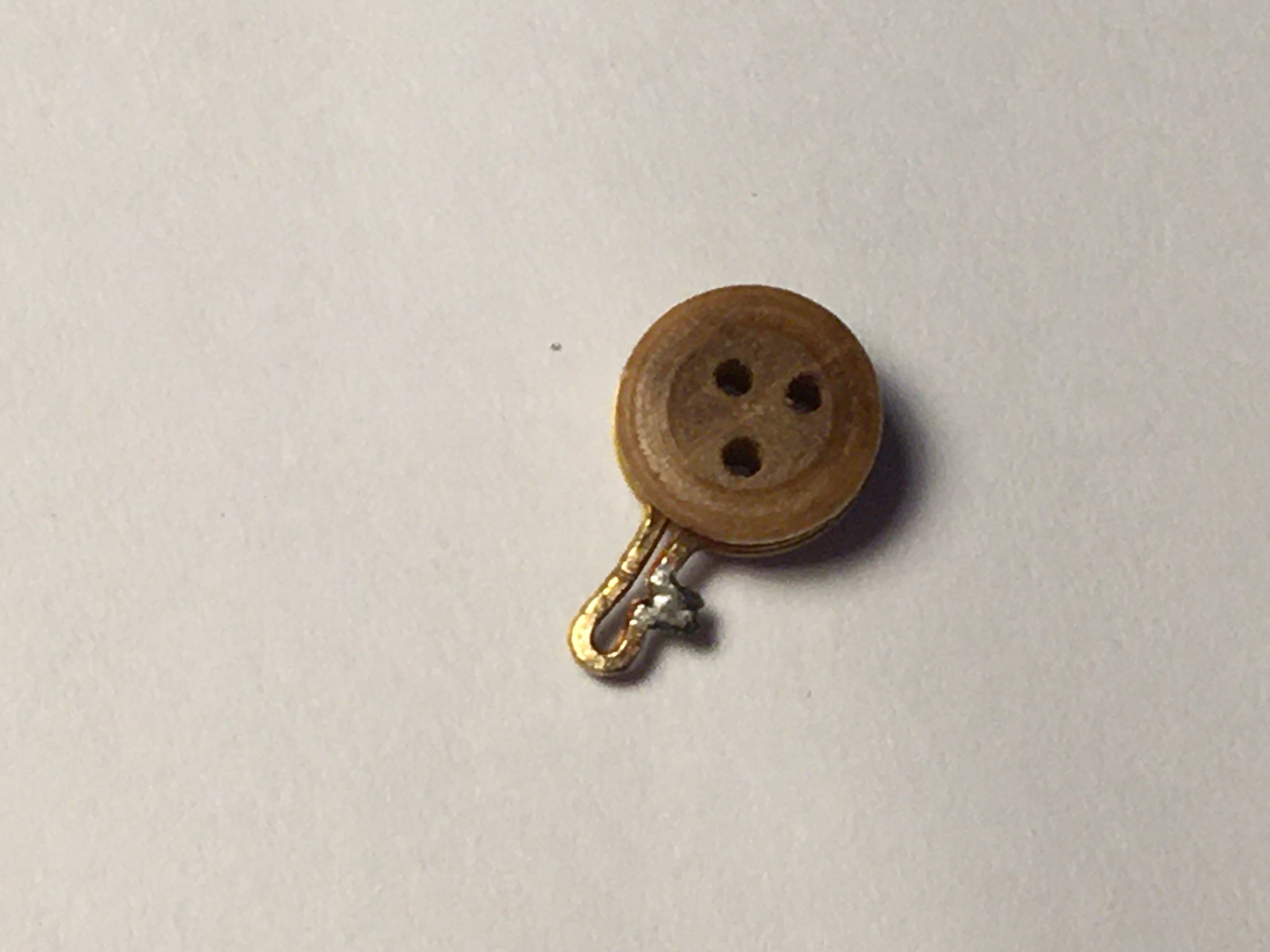
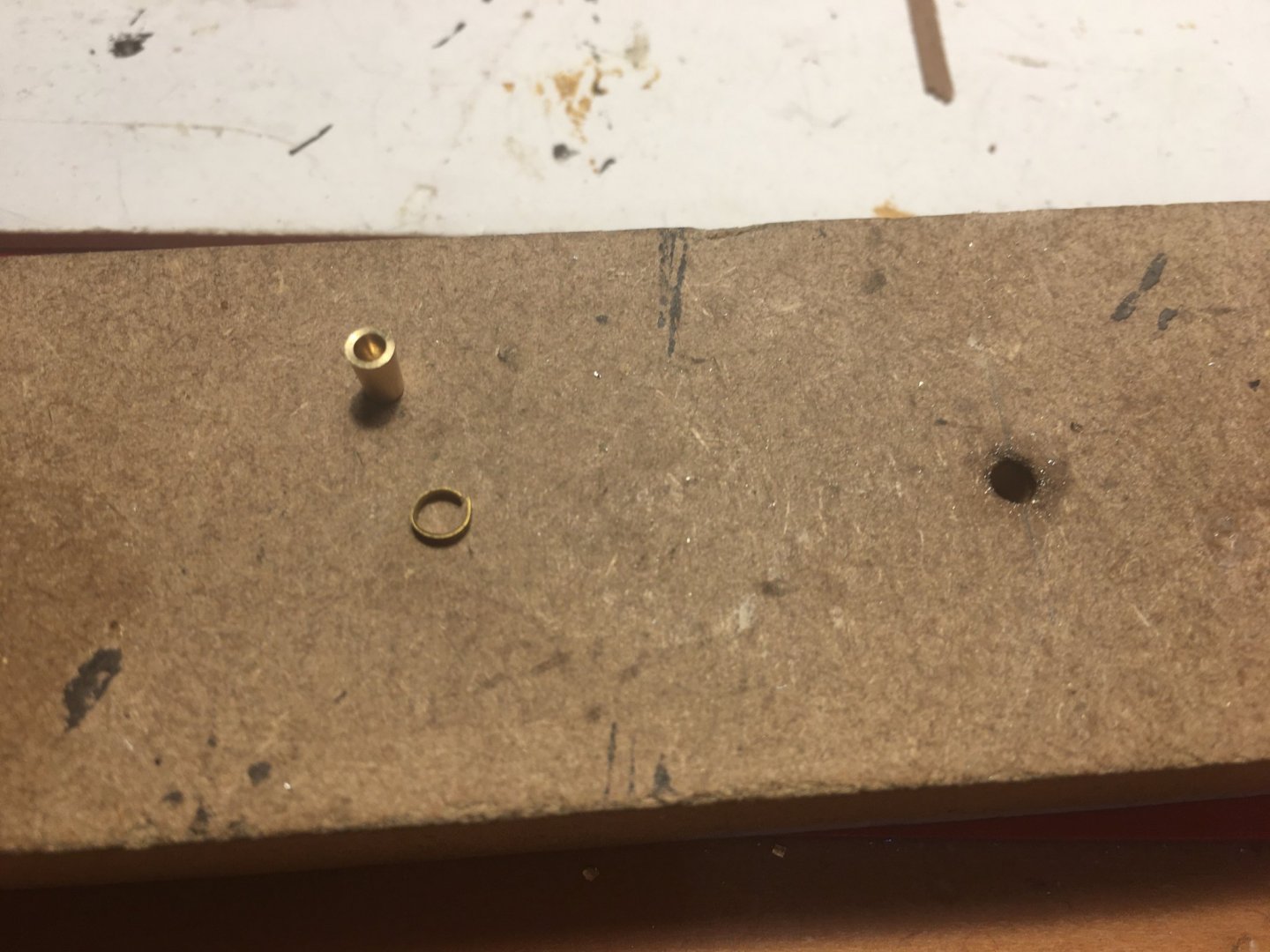
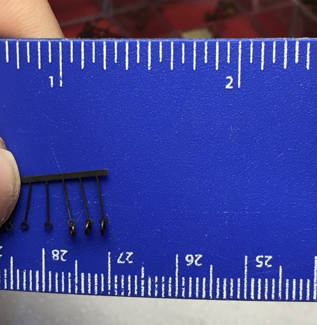
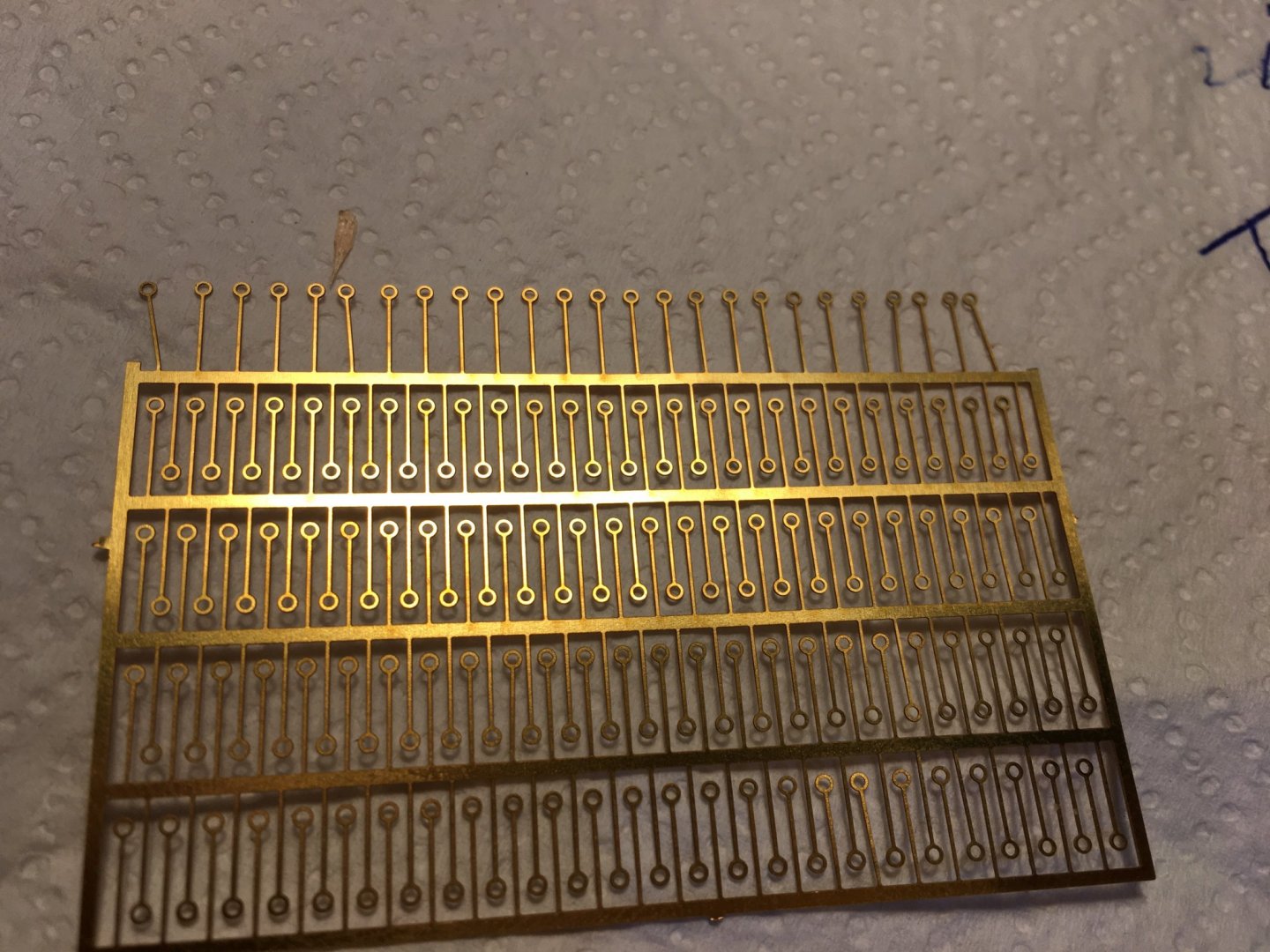
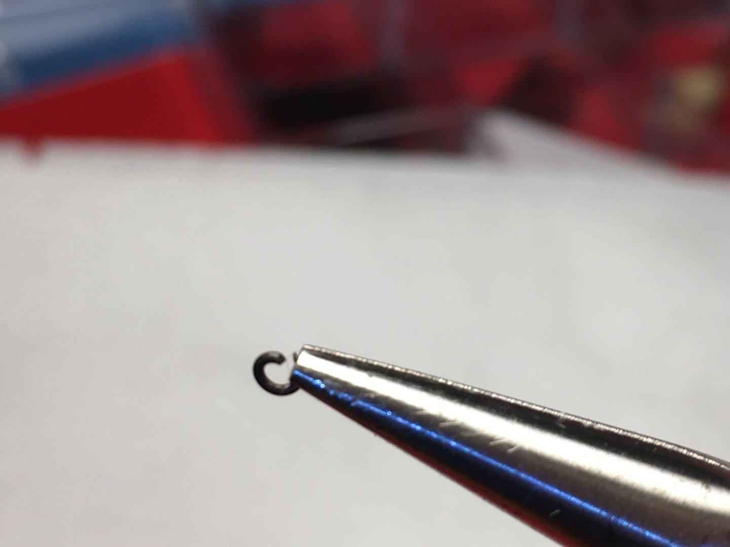
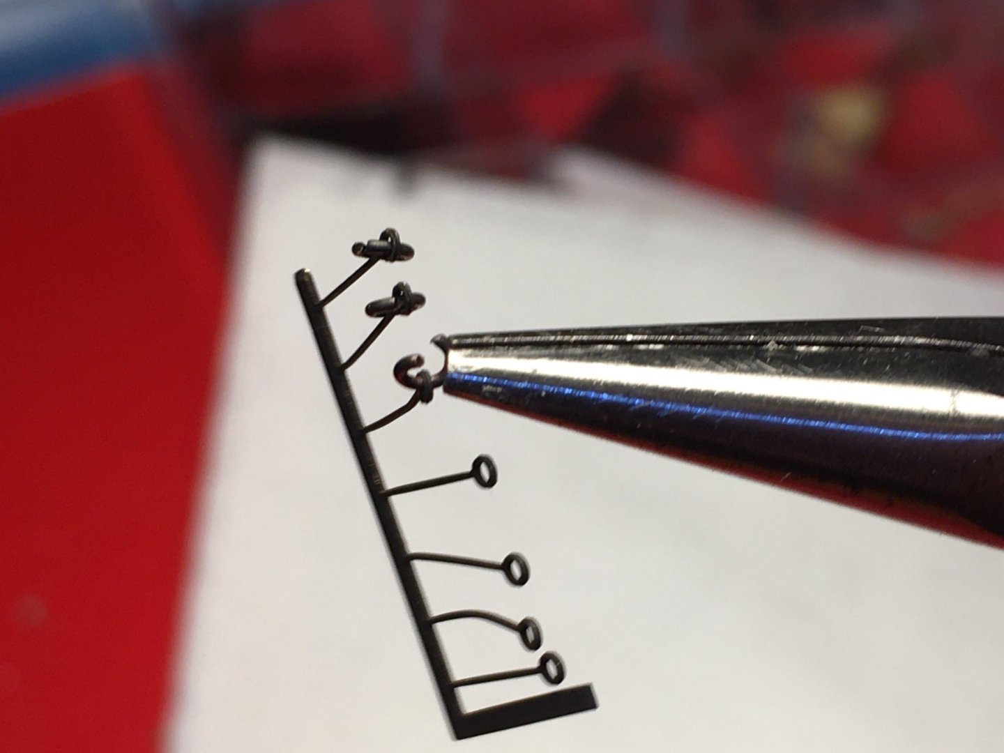
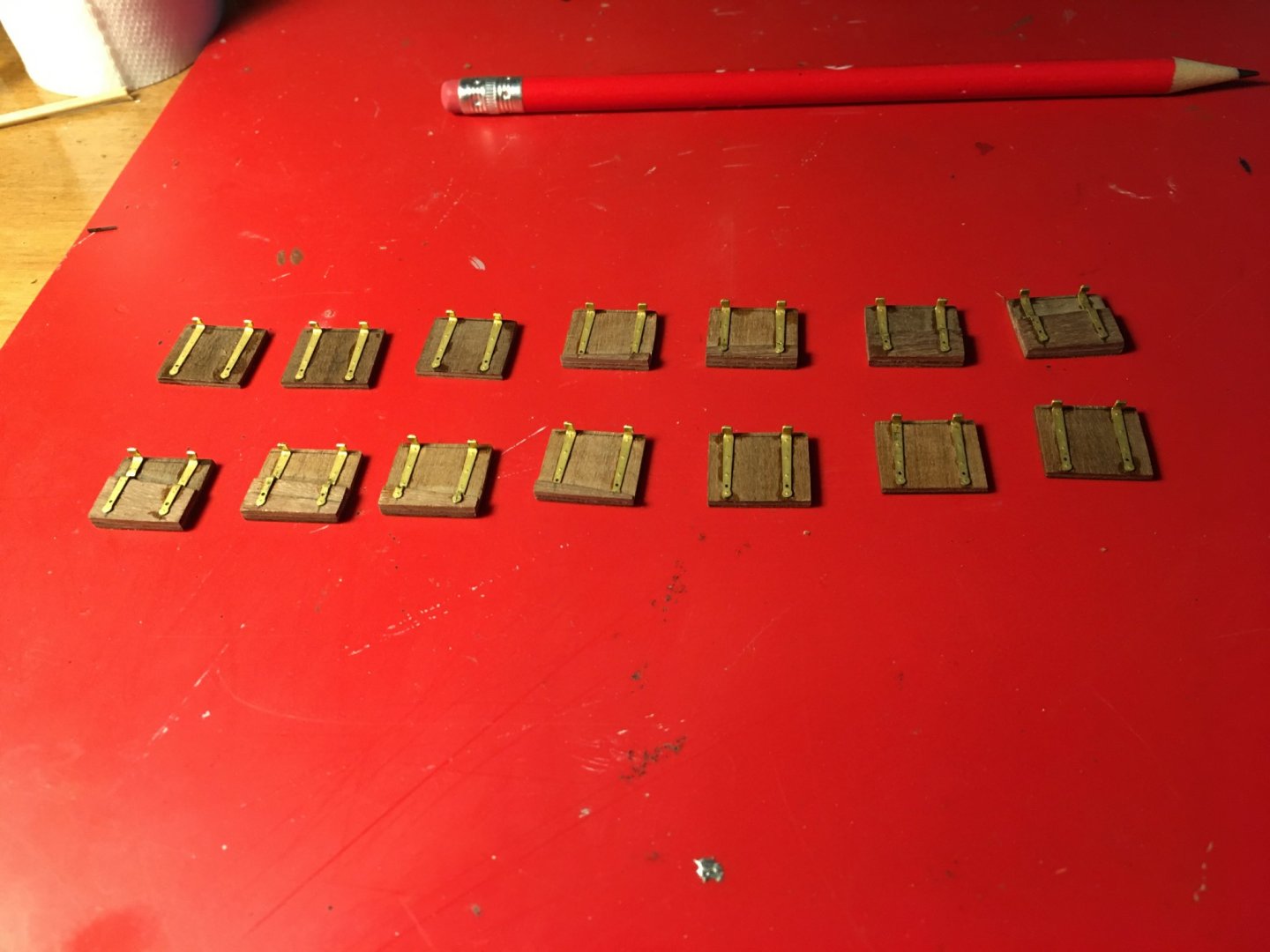
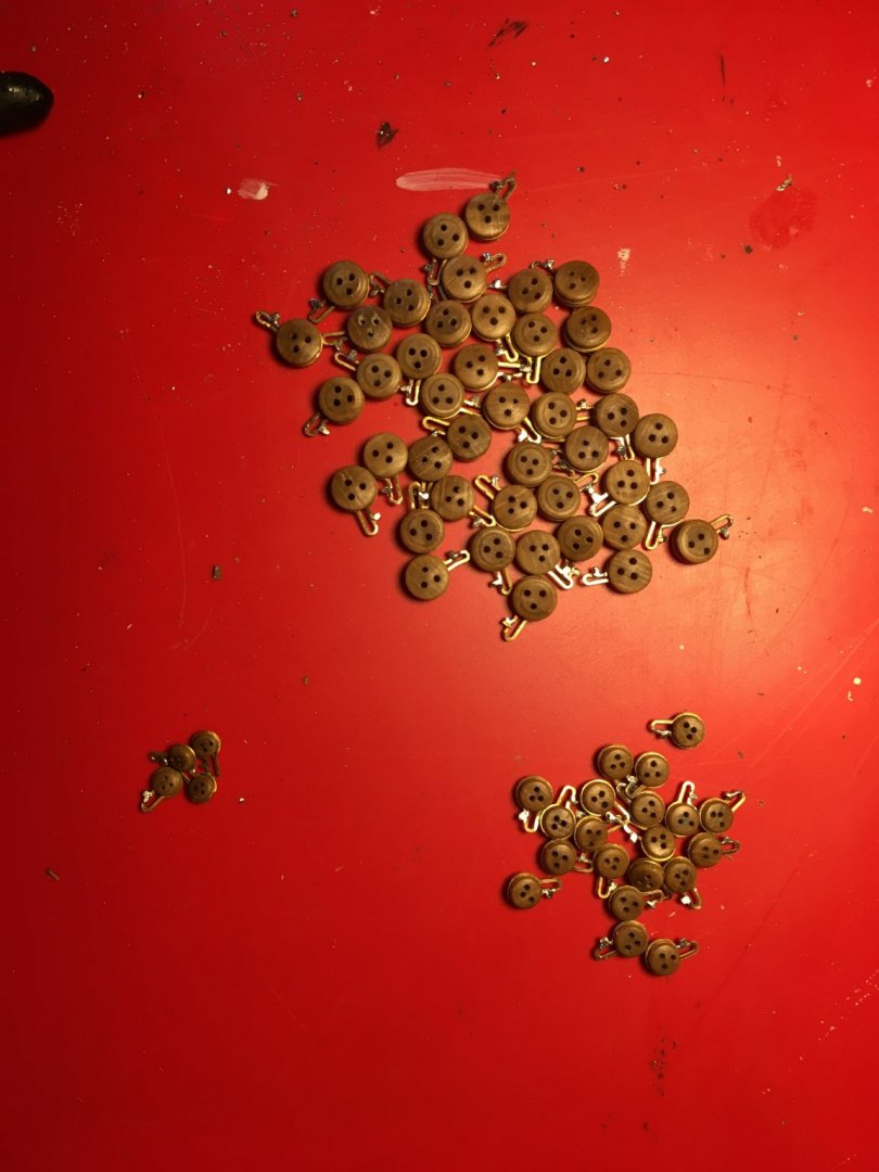
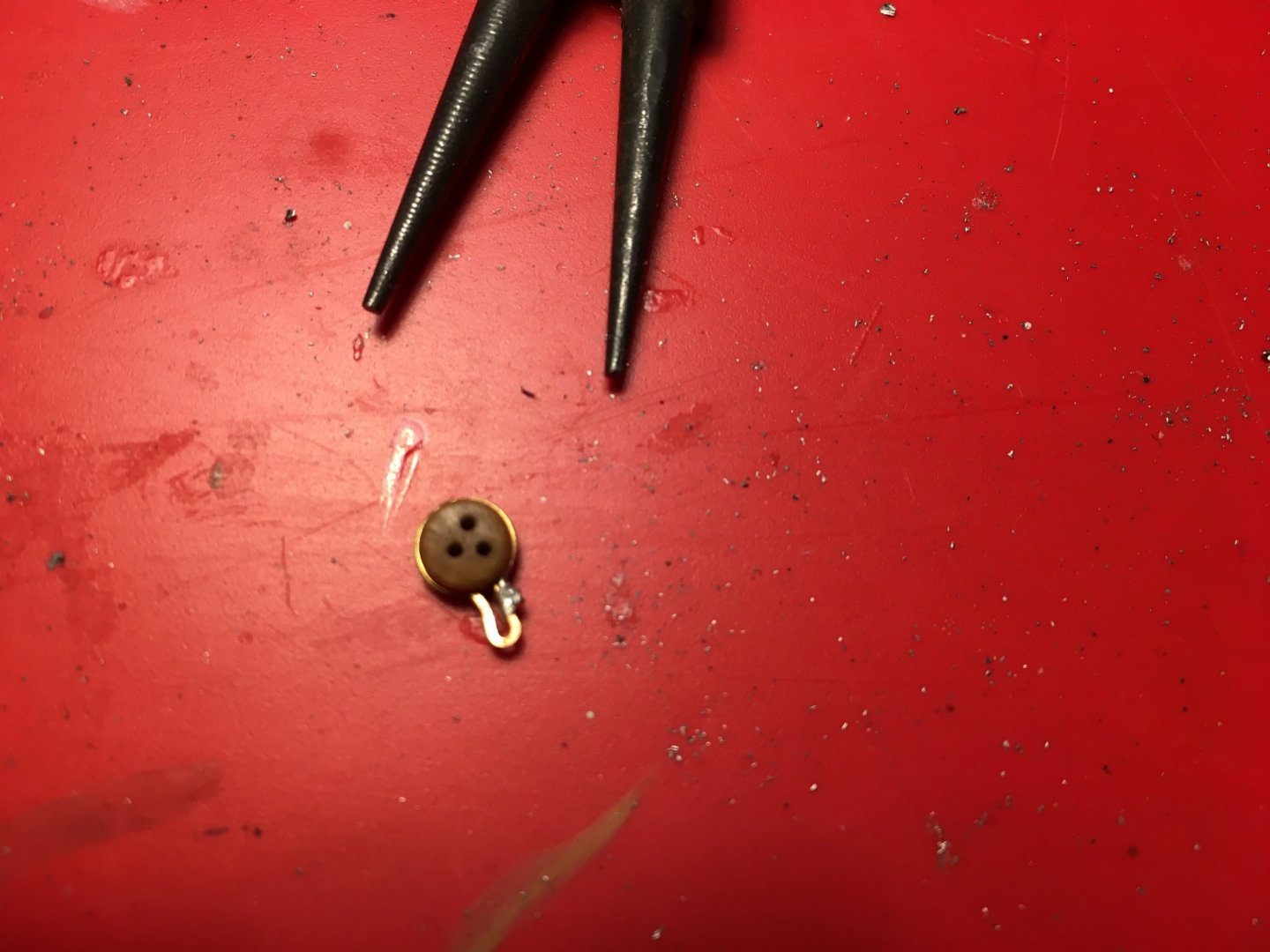
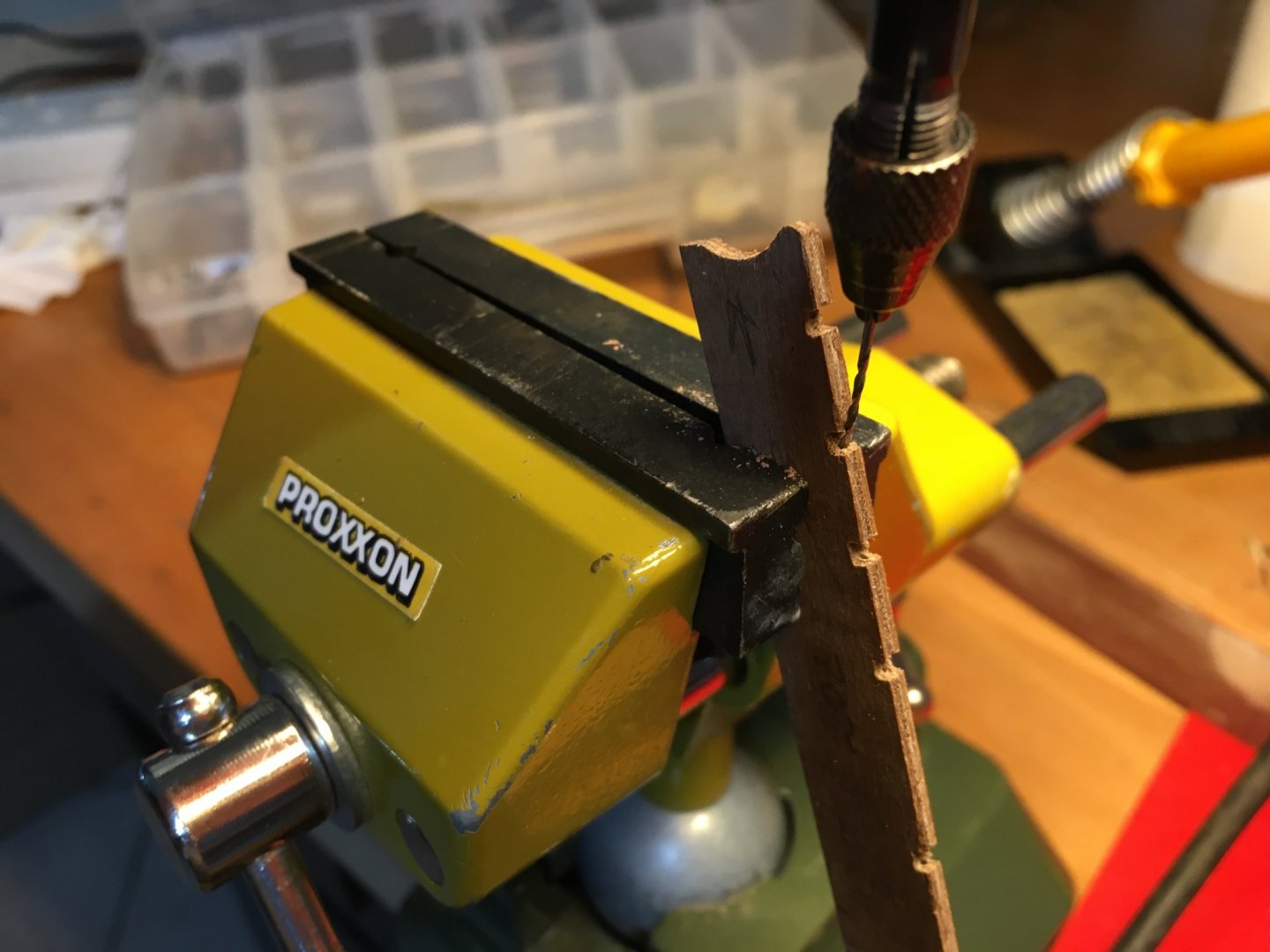
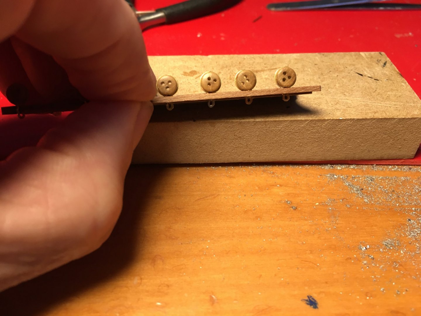
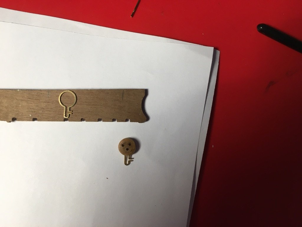
Although I don't intend to fit the gunport lids for the moment I thought I better start preparing some of their accessories as they involve a lot of repetitive work and will get a bit boring. This way I can do work on them every so and then. I have the lids for the quarterdeck gunports ready. I had prepared them as I needed to fit a few of them before the Channels. I started with preparing the eyelets and the rings for the lids, four sets for each lid. In the manual it only mentions the eyebolts for the gunport lids but in my opinion they look much better with the rings as well. I ordered some more small eyelets like the once supplied with the kit but the problem was with the rings. I couldn't find ready made rings small enough for the job. I ordered a roll of 0.5mm diameter copper wire, cut a piece of it, wind it round a 1.2mm drill bit, pull the drill bit out and wit a small pointed side cutter cut the rings from the winded wire. The small eyelets come in a photo etched sheet. I cut them in smaller pieces to be able to blacken them but left them mounted as it will be much better to handle them to fit the rings on them. Eyelets and rings blackened. Rings fitted to eyelets. All 244 sets I need plus a few extra to compensate for any I damage while mounting them on the lids are ready. The legs of the eyelets are very thin and easily damaged while fitting them. Robert

- 527 replies
-
- 7
-
-
- caldercraft
- victory
- (and 1 more)
-
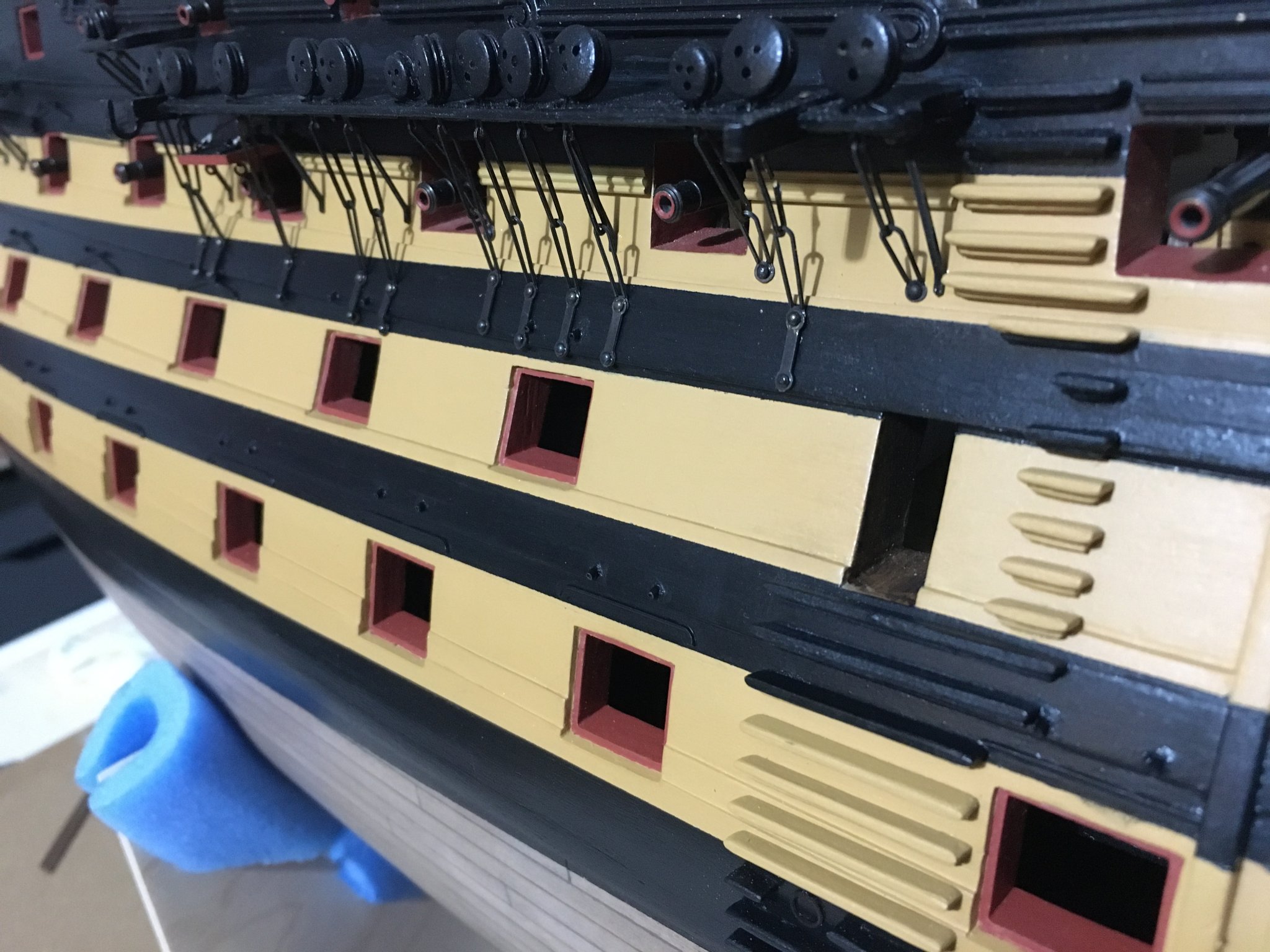
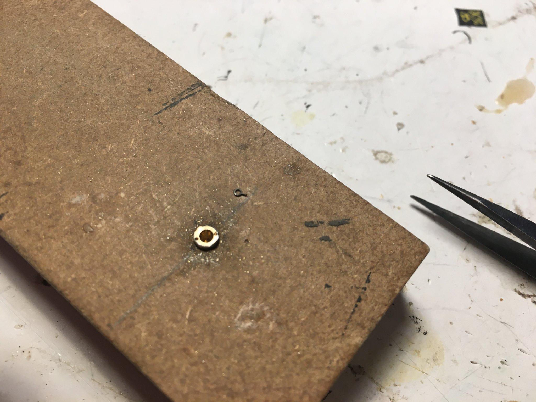
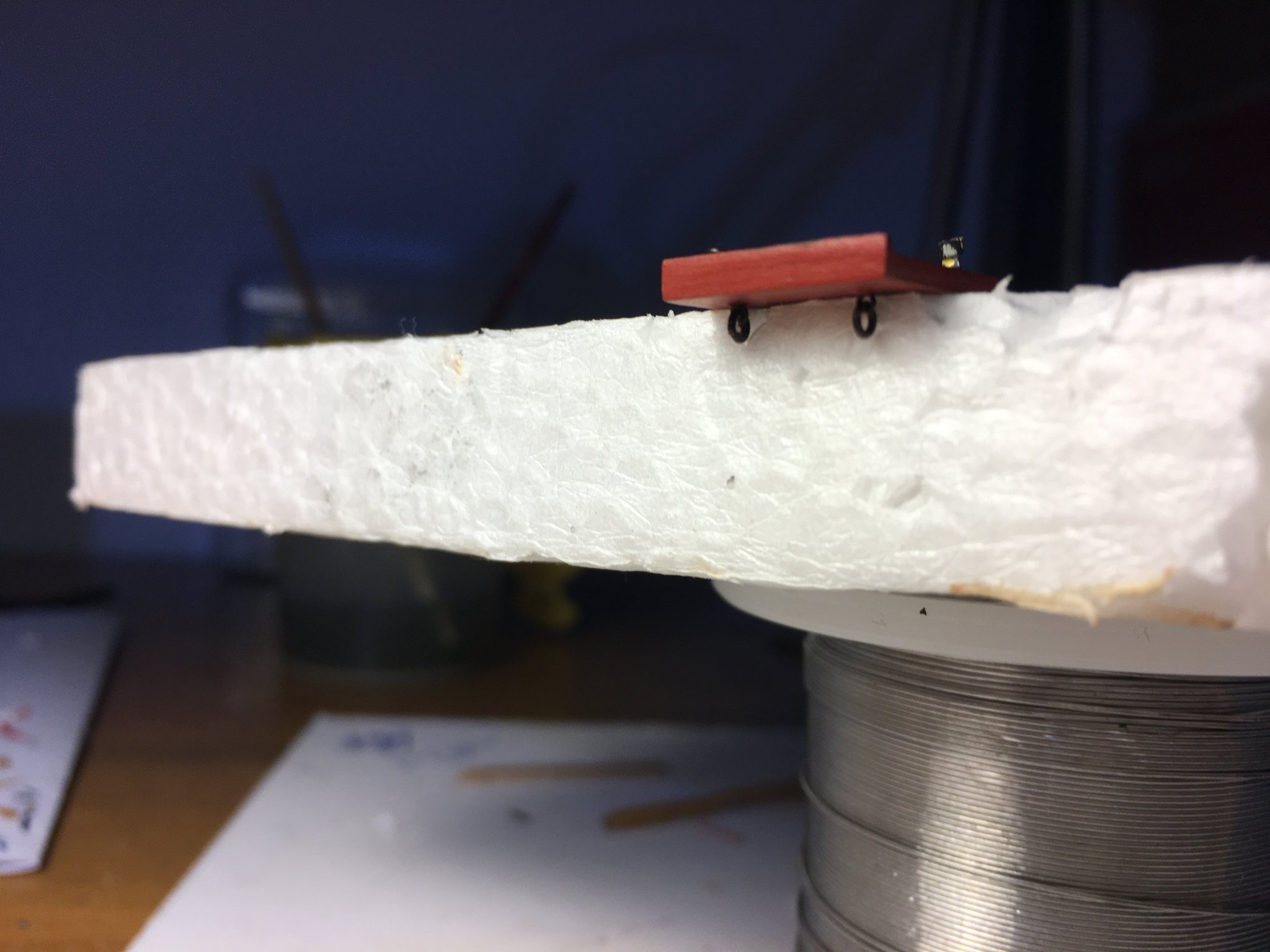
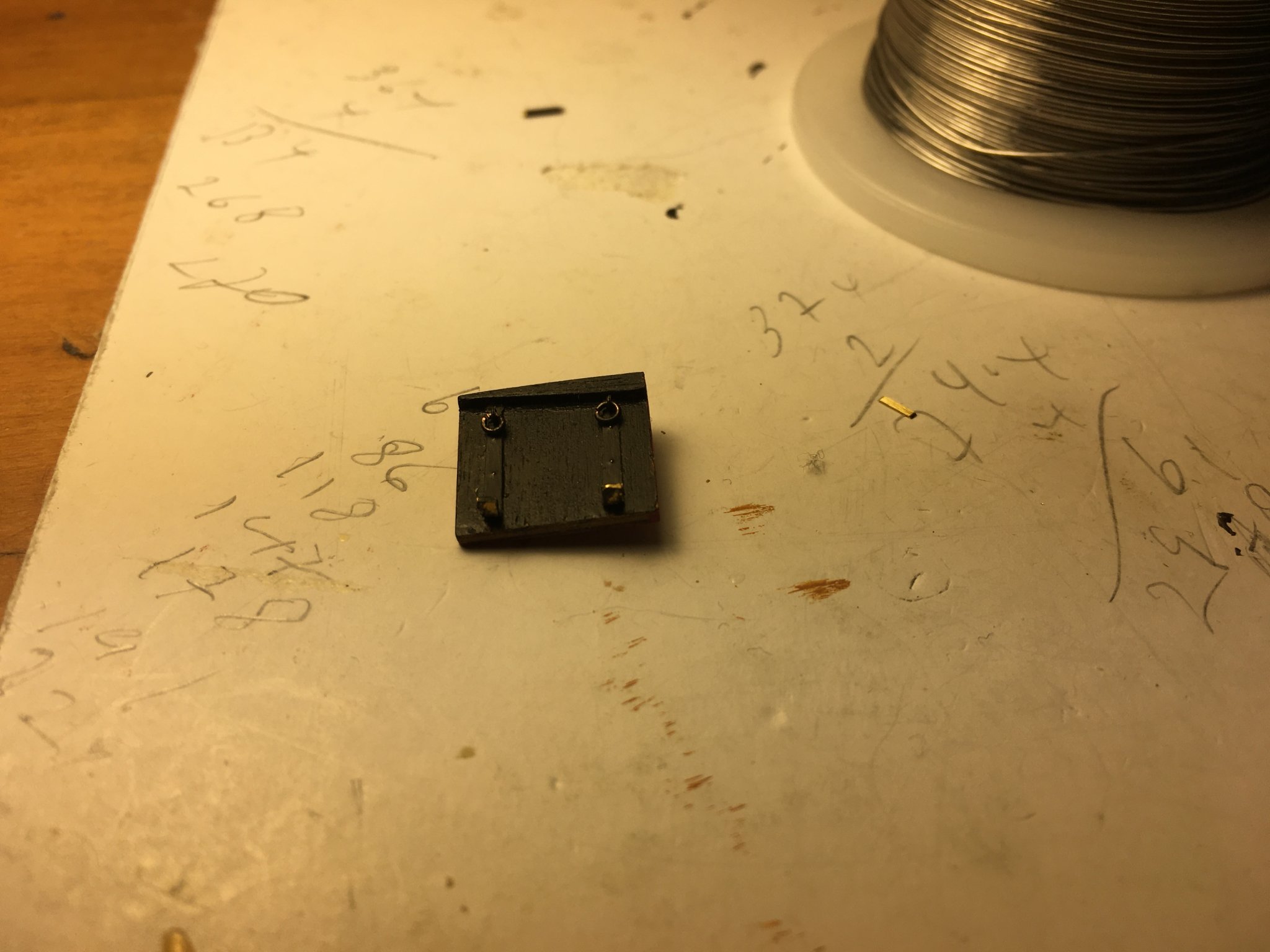
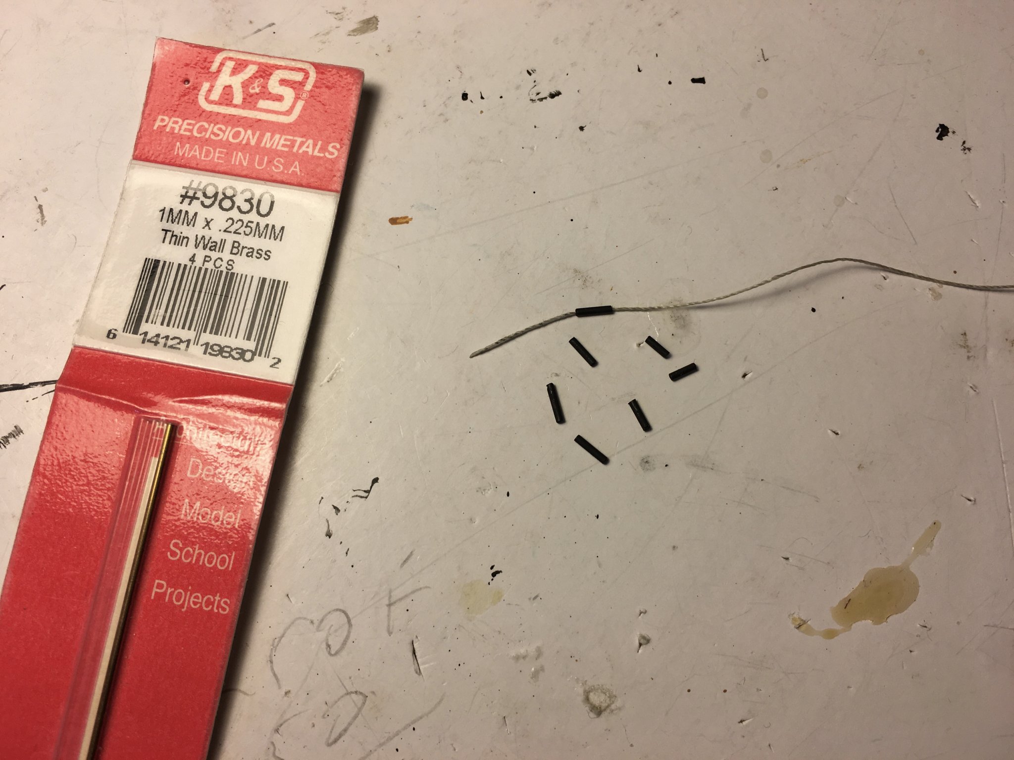
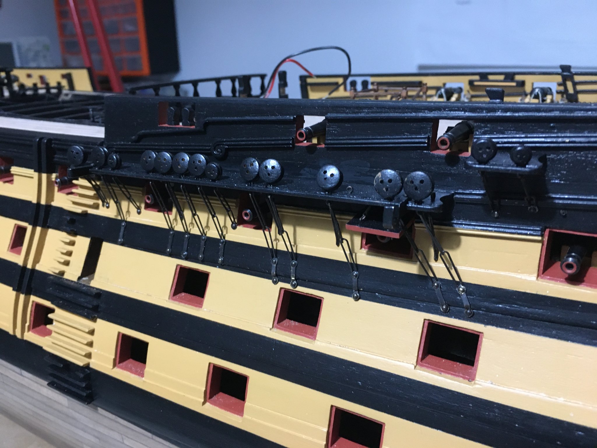
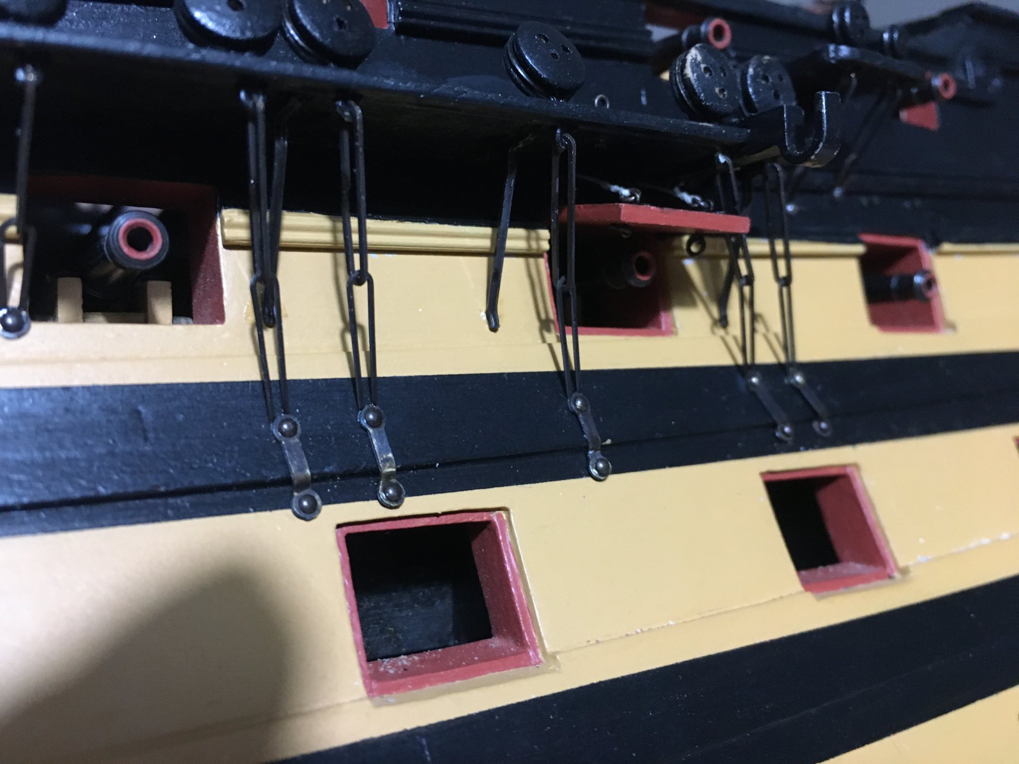
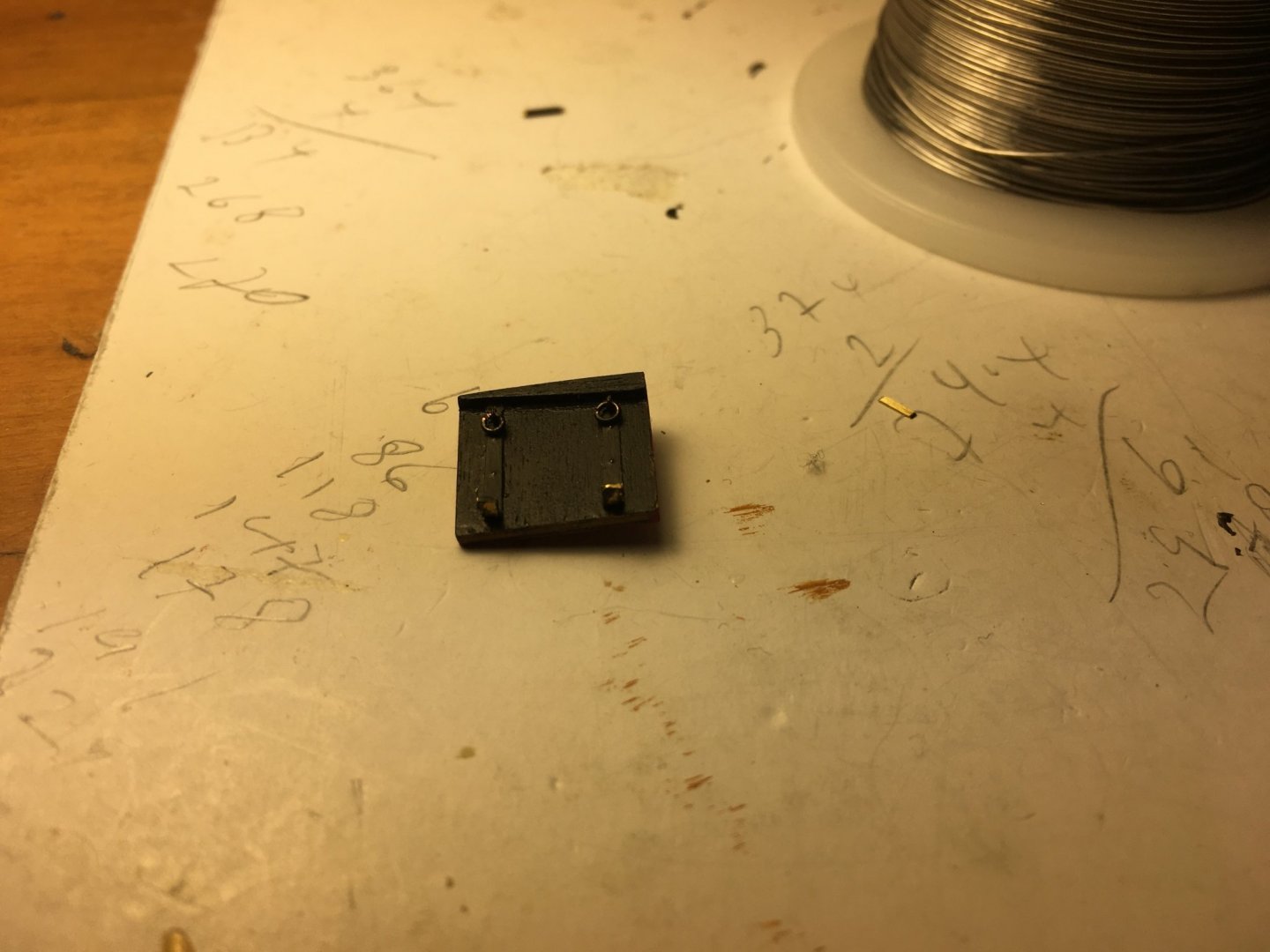
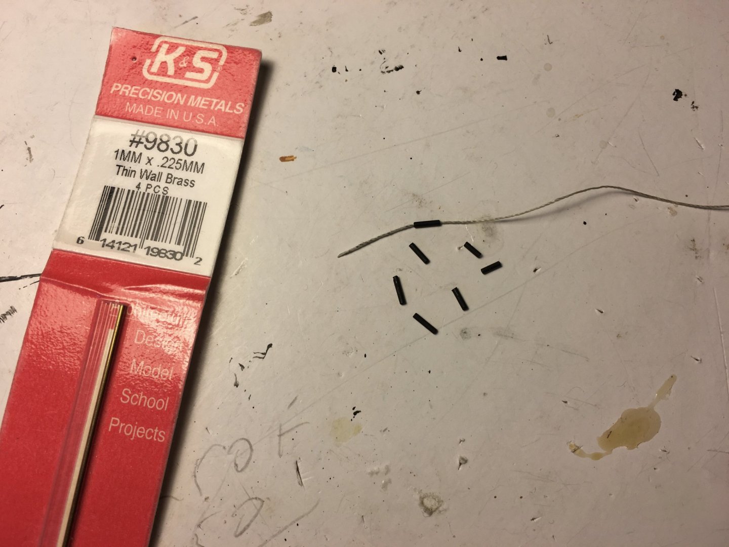
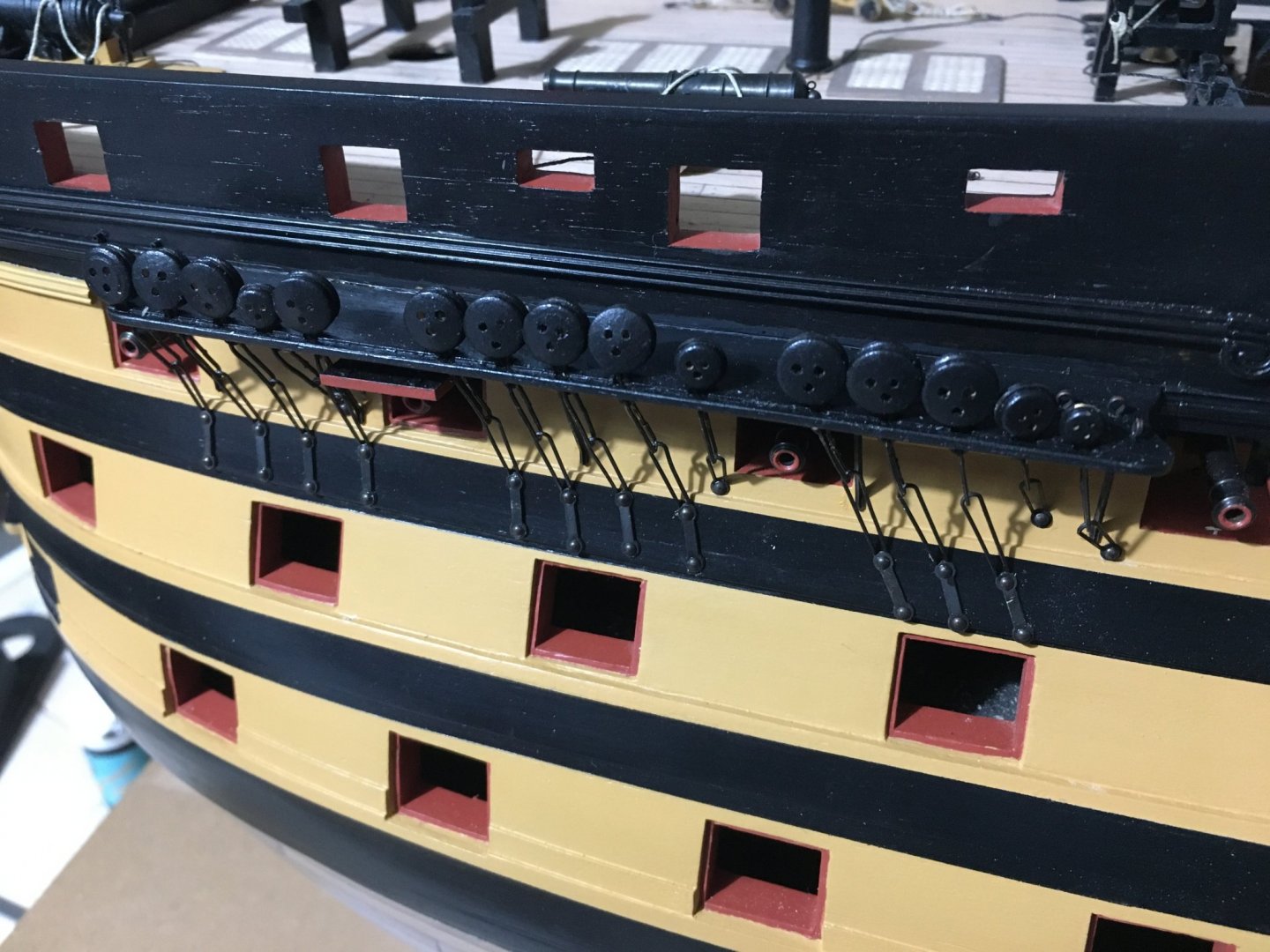
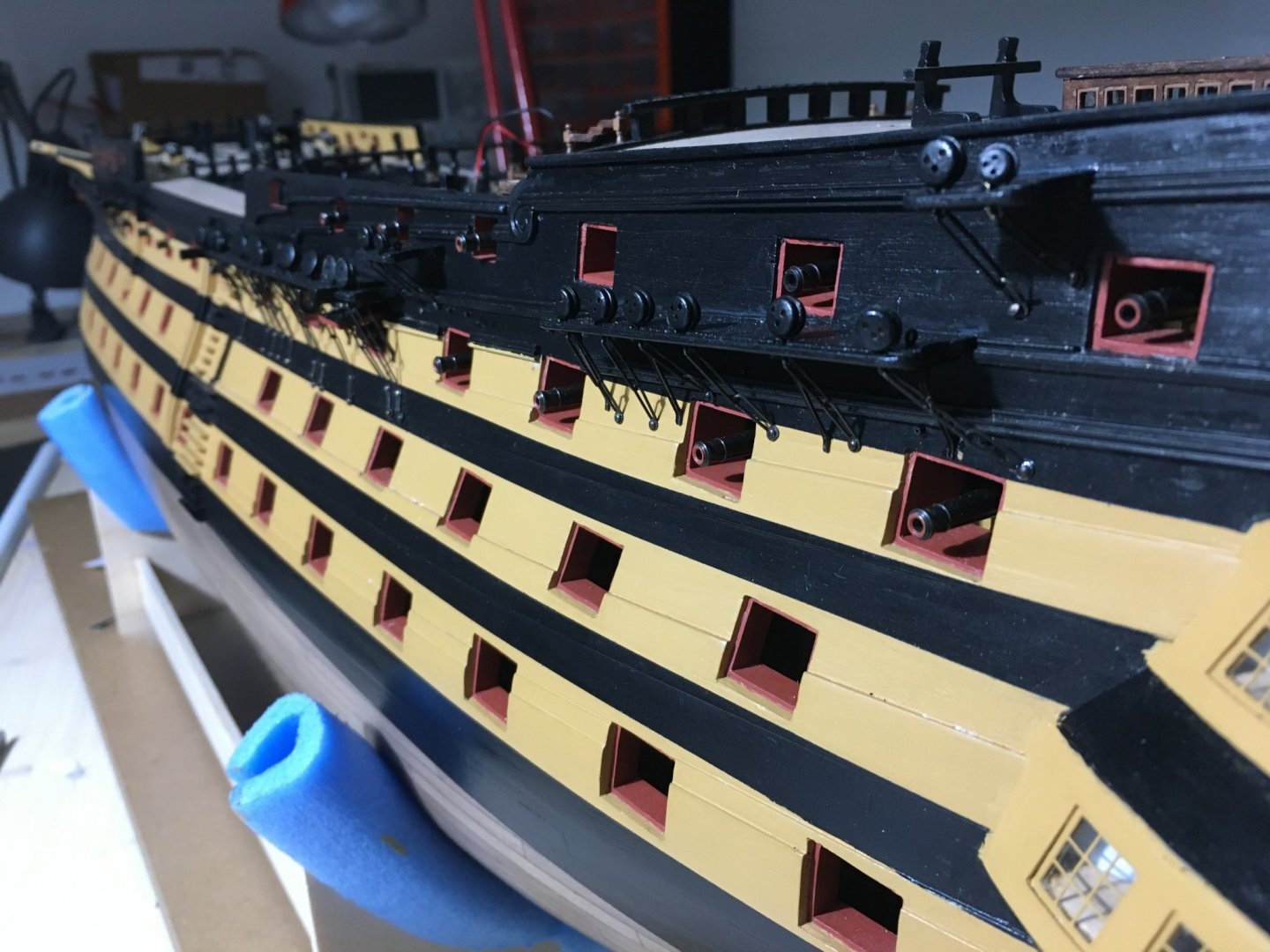
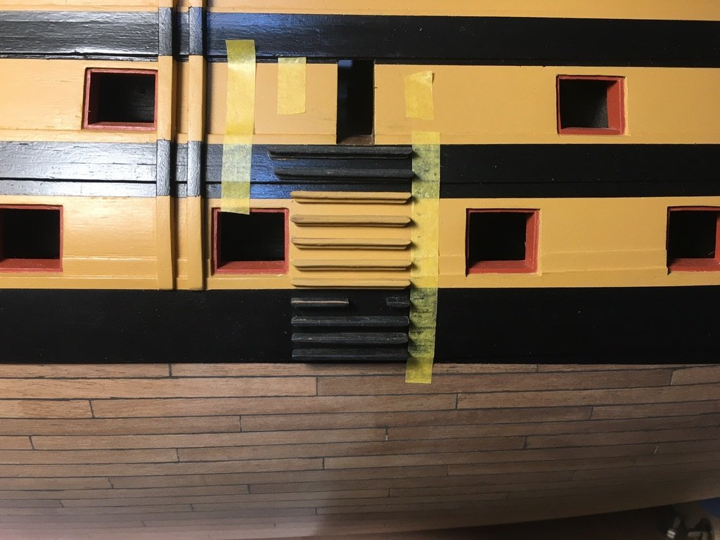
I have shaped the profiles that have to run from the cat-head supports to the upper rail. It wasn't easy, I had to heat the profile to bend sideways. Continued work on the upper gundeck lids. Fixed hinges. Fixed eyelets, the 3mm once supplied with the kit and added rings to them I made from copper wire as I couldn't find small enough for the job. Adding thread to the gun-port lids. In the instructions manual it tells you to drill 5mm holes in the hull and insert the other end of the thread in it. I wanted to make something more realistic to the real once. I had some very small brass tubing, 1mm x .225mm thin wall, cut very small pieces, about 4mm/5mm in length and blackened them. I will drill a hole in the hull were the tubing will be inserted and glued leaving just a small part protruding out. The thread will be inserted inside the tube. This is one of the lids fitted in place. There are a few of the lids which are just under the channels and it would be very difficult to fit with the channels in place so I fitted them before the channels. I fitted the chain plates to the dead eyes before I glued the channels in place. I blackened the chain plates. When I dry fitted the channels I realised that for some reason the base of the chain plates that is pinned to the hull was not really in the right place, they were lower. Good thing the channels were still just dry fitted because I had to reopen some of the chains and shorten them by cutting off part of them and reshaping them again. Profile from cat-head support to rail in place, black paint needs retouching. Channels fitted in place and chain plates pinned in place. This is the port side. Still have to pin the chain plates on the starboard side as I ran out of round headed pins and I am waiting for some more from CBM. When pinning the lower parts of the chain plates I suggest you temporarily block the gunports below, I used masking tape, as it is quite easy to drop the lower part of the chain plate inside one of them and there is no way you can get it back and you have no extra once. Don't remember how many times I dropped them on the floor and had to look for them until I find them knowing I have no extras. Robert


- 527 replies
-
- 12
-
-
- caldercraft
- victory
- (and 1 more)
-
Hello Heinz, was wondering when were we going to start seeing your amazing work on the Victory again. It's a real pleasure following your build log. The rigging is looking amazing. Robert
-
Good to start seeing your beautiful work again Paul. My progress on the Victory is still a bit behind you so its very interesting following your log. Robert
-
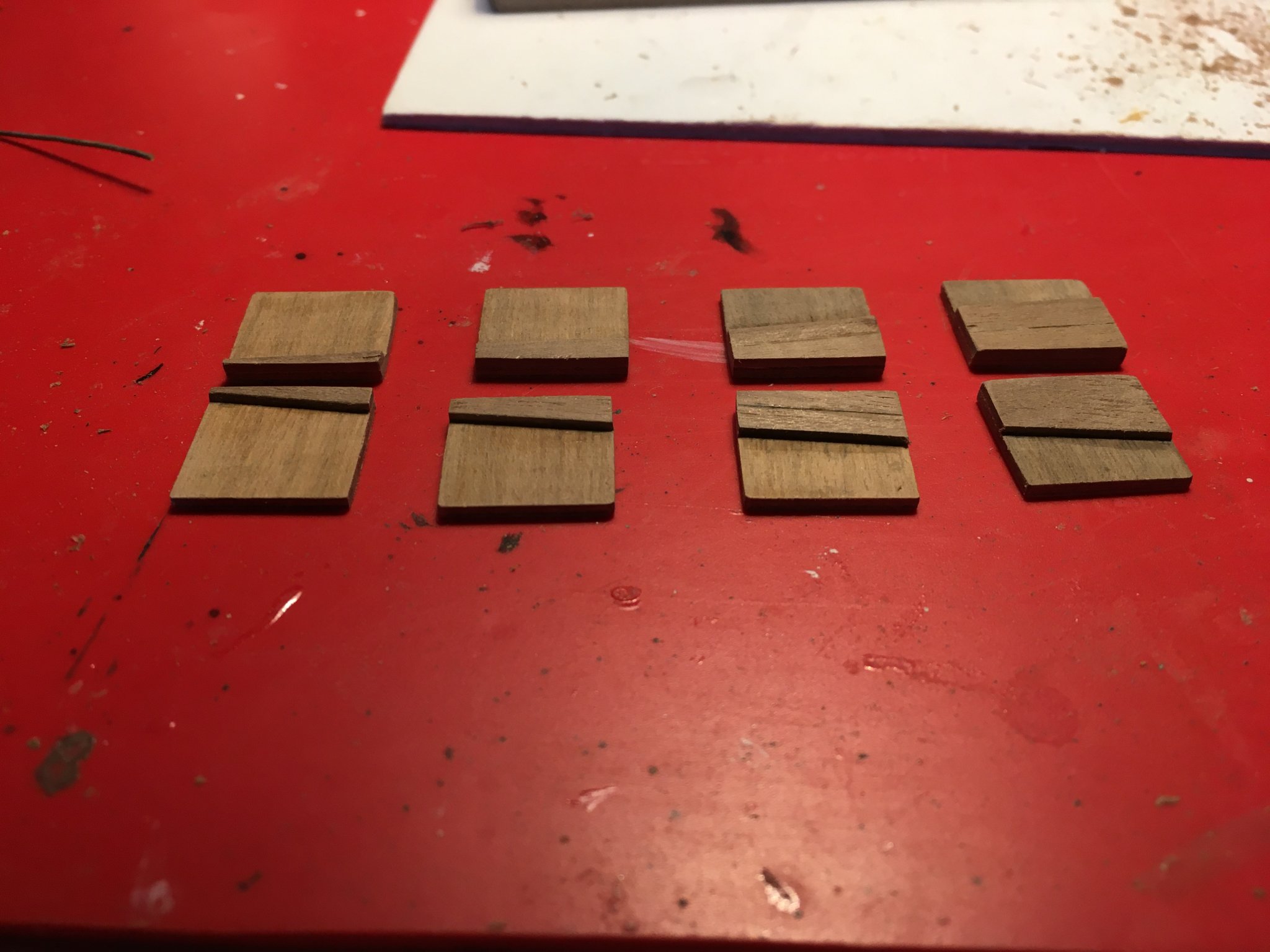
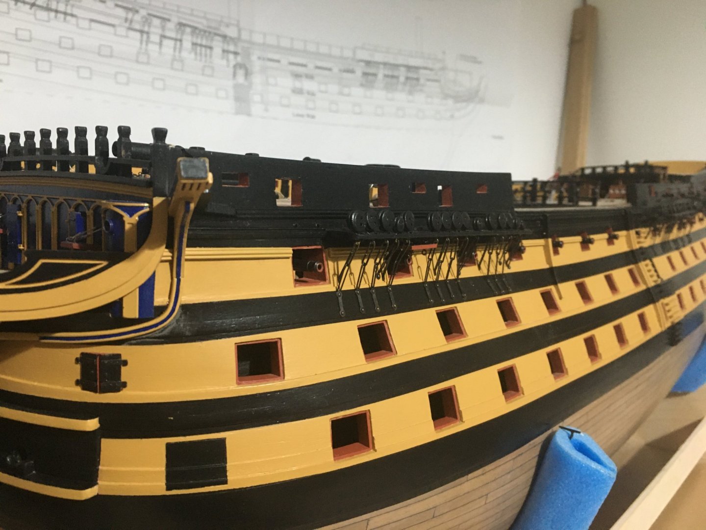
Wallace, Mort Stoll and Sailor thank you for you encouraging comments. I have a small update. Fitted all deadeyes on channels. I also fitted the eyelets and the studding sail boom brackets on the channels. On the brackets a added a small detail by drilling two holes in them and inserting two round headed nails in each bracket. I have also glued the nails in the holes on the channels edge which already have their corresponding holes on the side of the hull. I decided not to fix the channels in place for the moment. Some of the gunport lids and the thread for the upper gun deck are very close underneath the channels. I think it is much easier to fit these lids first and then the channels. So I started work on the gunport lids for the upper gun deck. Glued 1mm walnut strips corresponding with the Wales going across them. Robert

- 527 replies
-
- 5
-
-
- caldercraft
- victory
- (and 1 more)
-
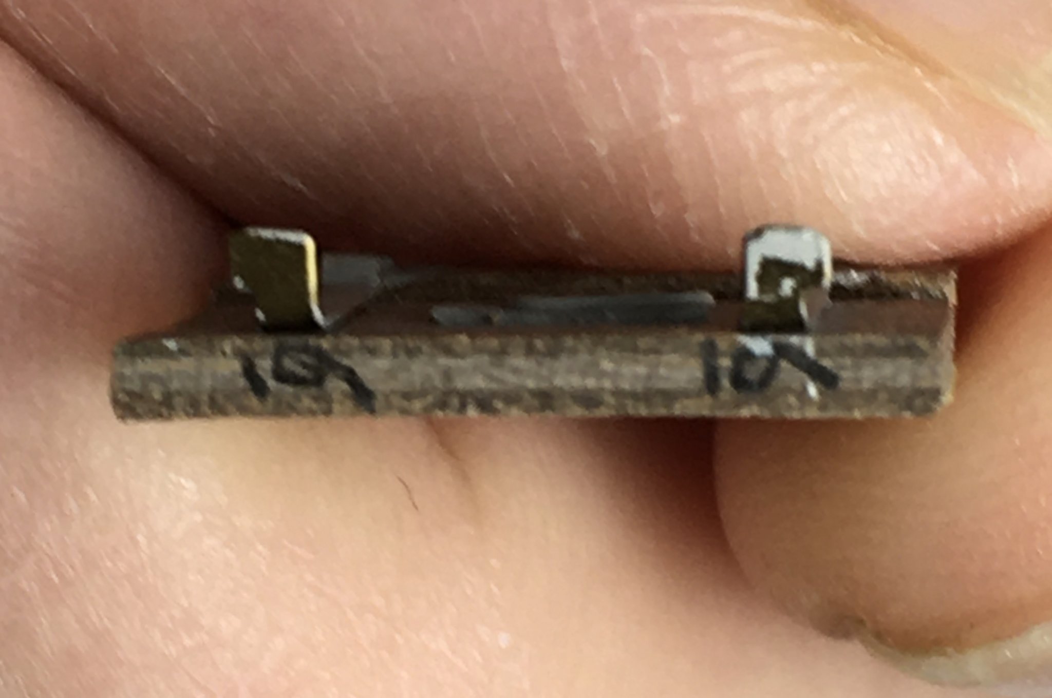
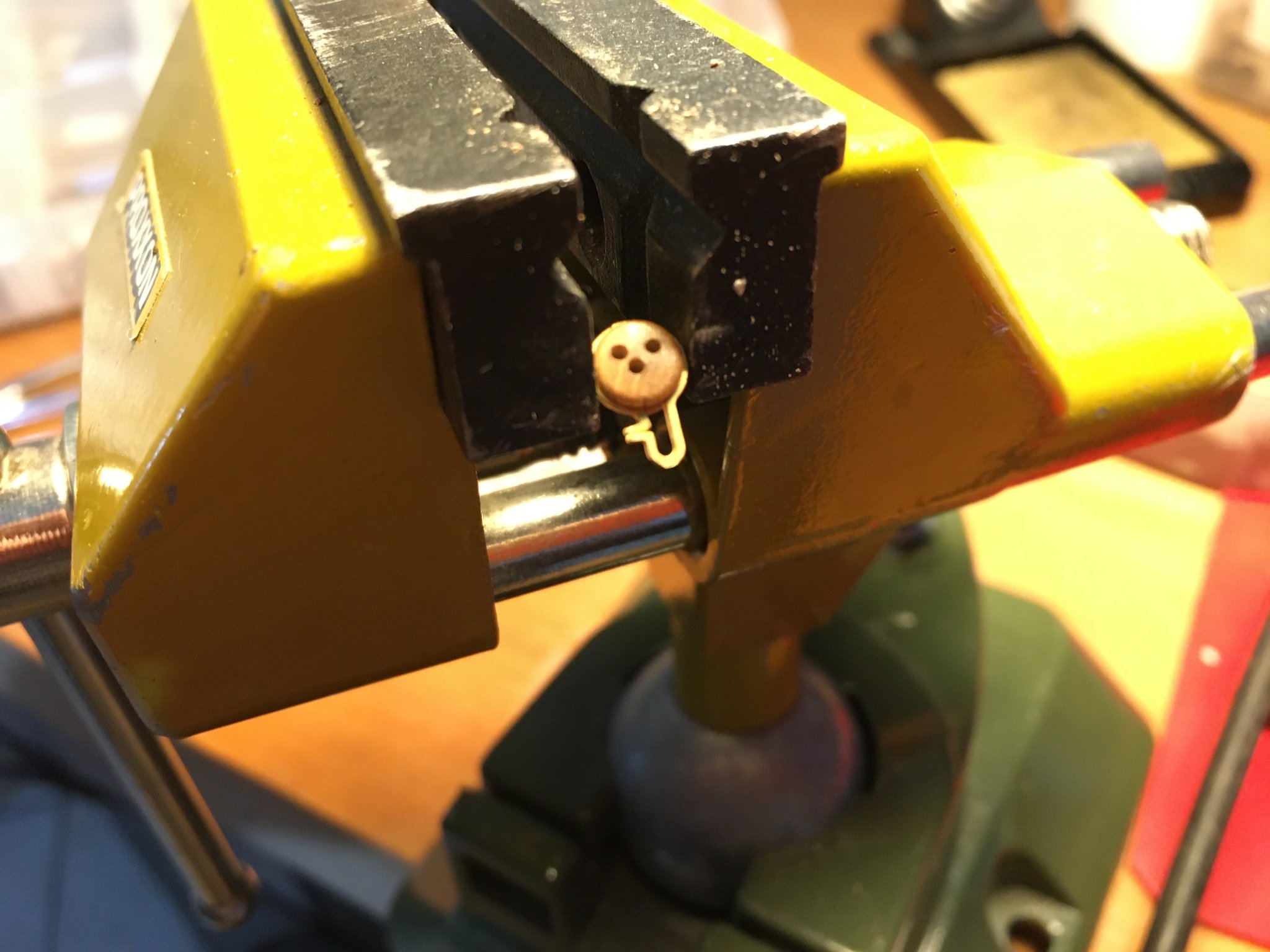
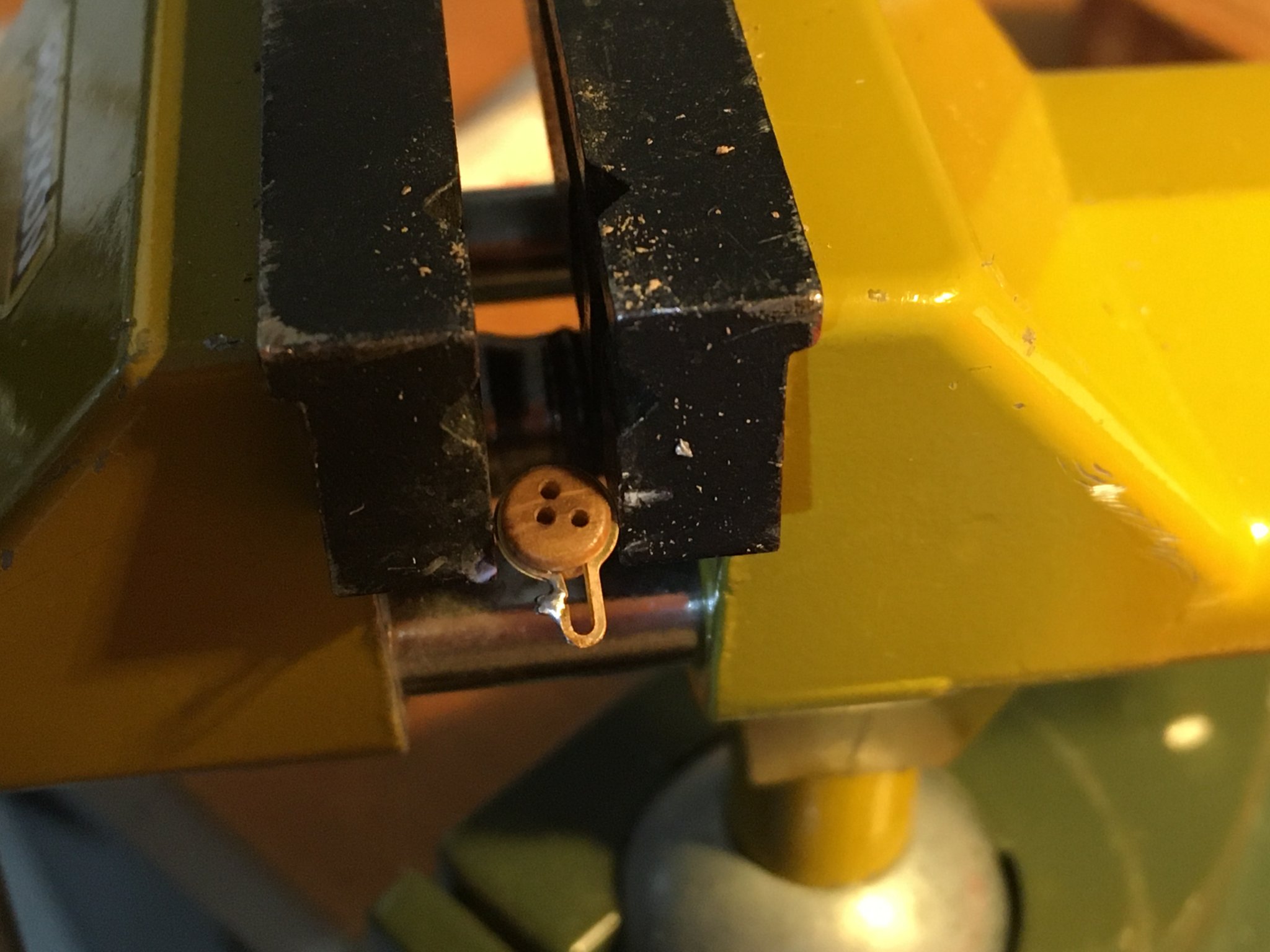
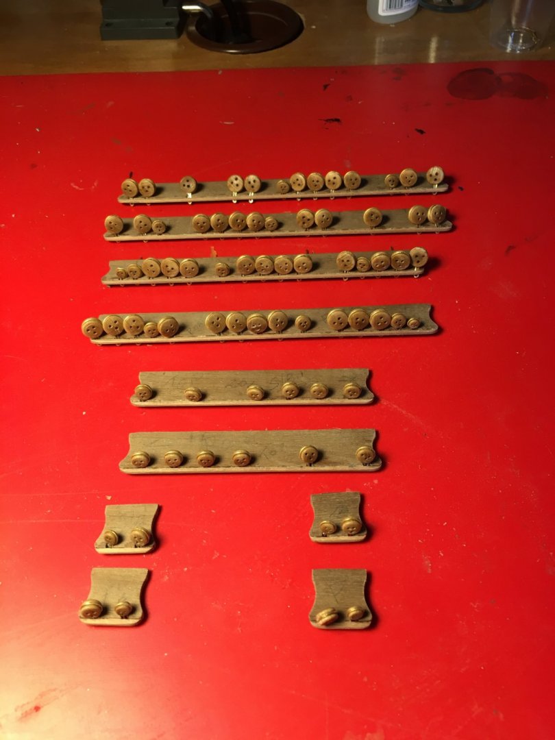
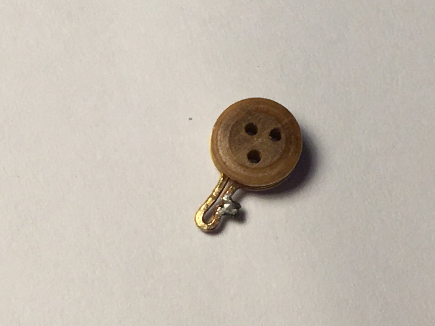
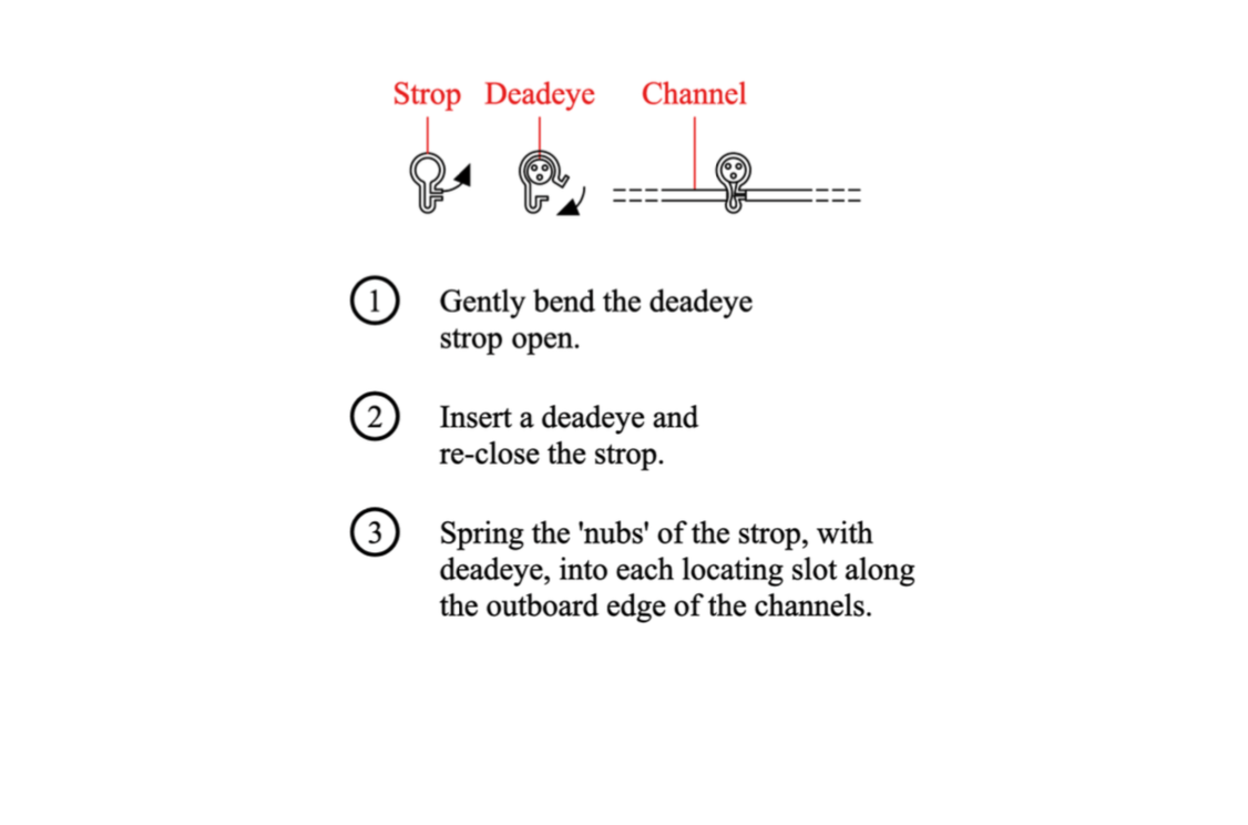
Still unsure how to go about fitting the deadeye strops I sent an email to Caldercraft and by the following day I received a pdf file with the attached details and told me that the nubs are pressed into place on the channel which compresses this section of the strop and this compression helps to hold the strop while the shrouds/chainplates etc are fitted. To make sure the strops won't prise open or move from place while fitting the shrouds and chainplates I decided to make some adjustments. I soldered the nubs together to make sure the strop does not prise open. With a round nosed pliers I pressed together the middle of the lower part of the strop. Drilled a hole on the side of the slots on the channel to take the nubs, always on the same side. I reinforced the the wood around the holes by applying a drop of superglue. Fitted the strop in the slots on the channel at the same time inserting the nubs in the drilled hole. You might need to trim a bit of the slot edges to allow the strops to move just a bit sideways. Do not glue the strops with the channel, at least for now, as they have to be aligned in line with the shrouds. The soldered area will be covered when fitting the walnut strip across the edge of the channel. The images above show the 5mm deadeyes. The 7mm deadeyes will look something like this. I will upload more images of the finished channels later on as I have only tried the strops on one of the channels. I hope this upload will be of some help to anyone who encounters the same problem. Robert


- 527 replies
-
- 6
-
-
- caldercraft
- victory
- (and 1 more)
-
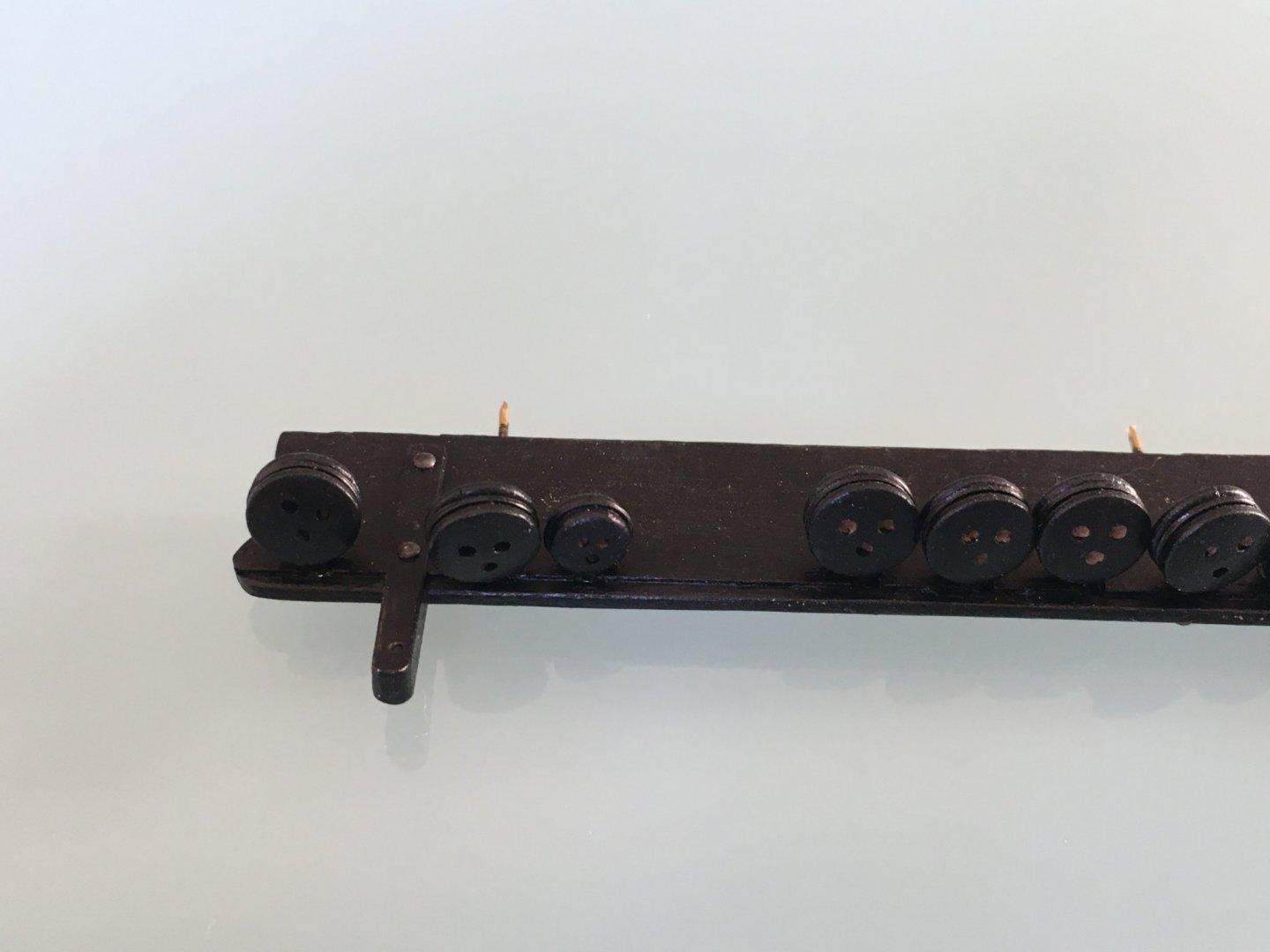
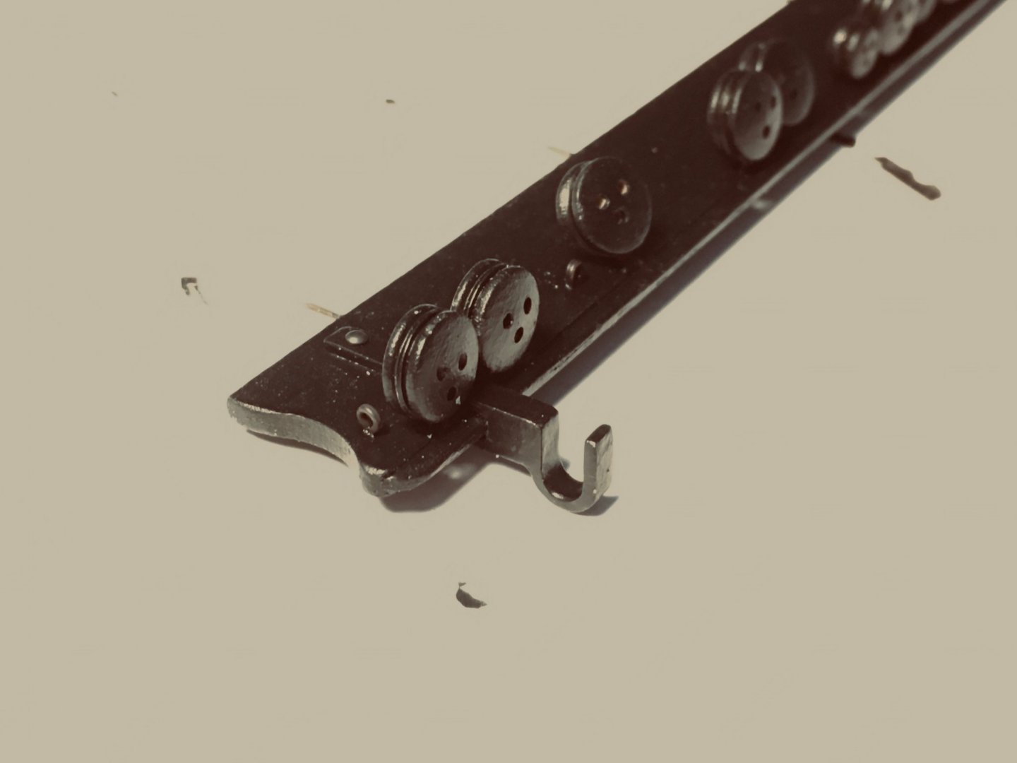
Thank you Michael for your comments and thank you all for the likes. I am about to start work on fitting the deadeyes to the Channels. I have a question as I am not sure if I am missing something on how the deadeyes in strops should be fitted to the channel. As you can see in the picture the strop is open on one side with the ends having another short length protruding at right angles. To be honest I cannot see any scope for these. I can solder the ends together so that the strop will not open when under tension from the shrouds. My question is 'should the protruding sides be trimmed off after I solder the ends as obviously the strop will not fit in the notch on the Channel, or am I missing something on how this should be fitted?' I cannot find any details in the kit manual. Would appreciate any tips. Robert
- 527 replies
-
- 5
-
-
- caldercraft
- victory
- (and 1 more)
-
Michael, just been through your build, lovely work. I can see that you go that extra mile to bring out that detail which makes a model stand out. In my opinion that extra effort you make to perfect the details as much as possible, which is not easy when working on such scale, makes all the difference on the finished model. My next project after I finish my current one, which is still quite a long way, might be a cross section model. I love the detail that can go into it. Robert
-
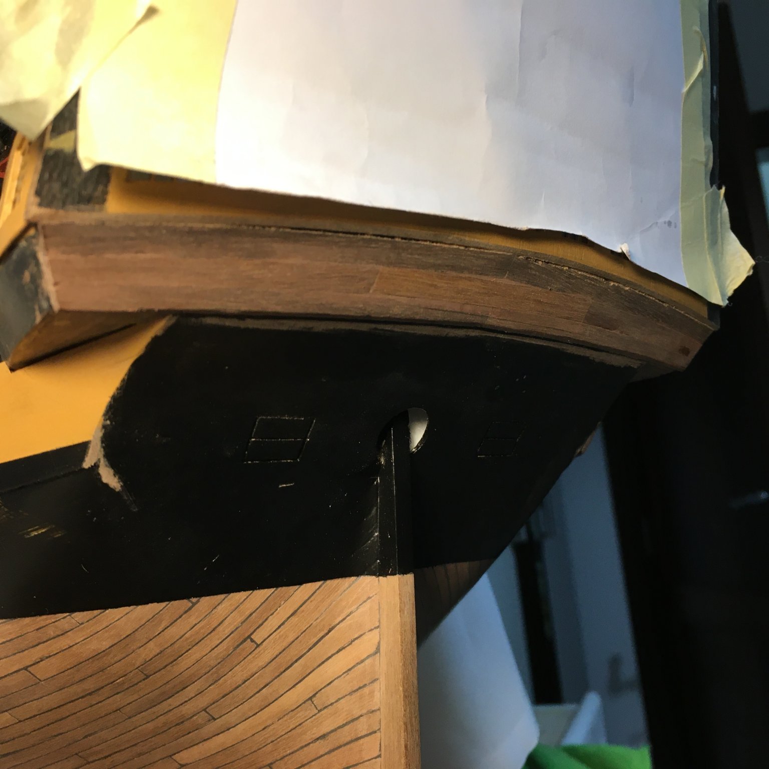
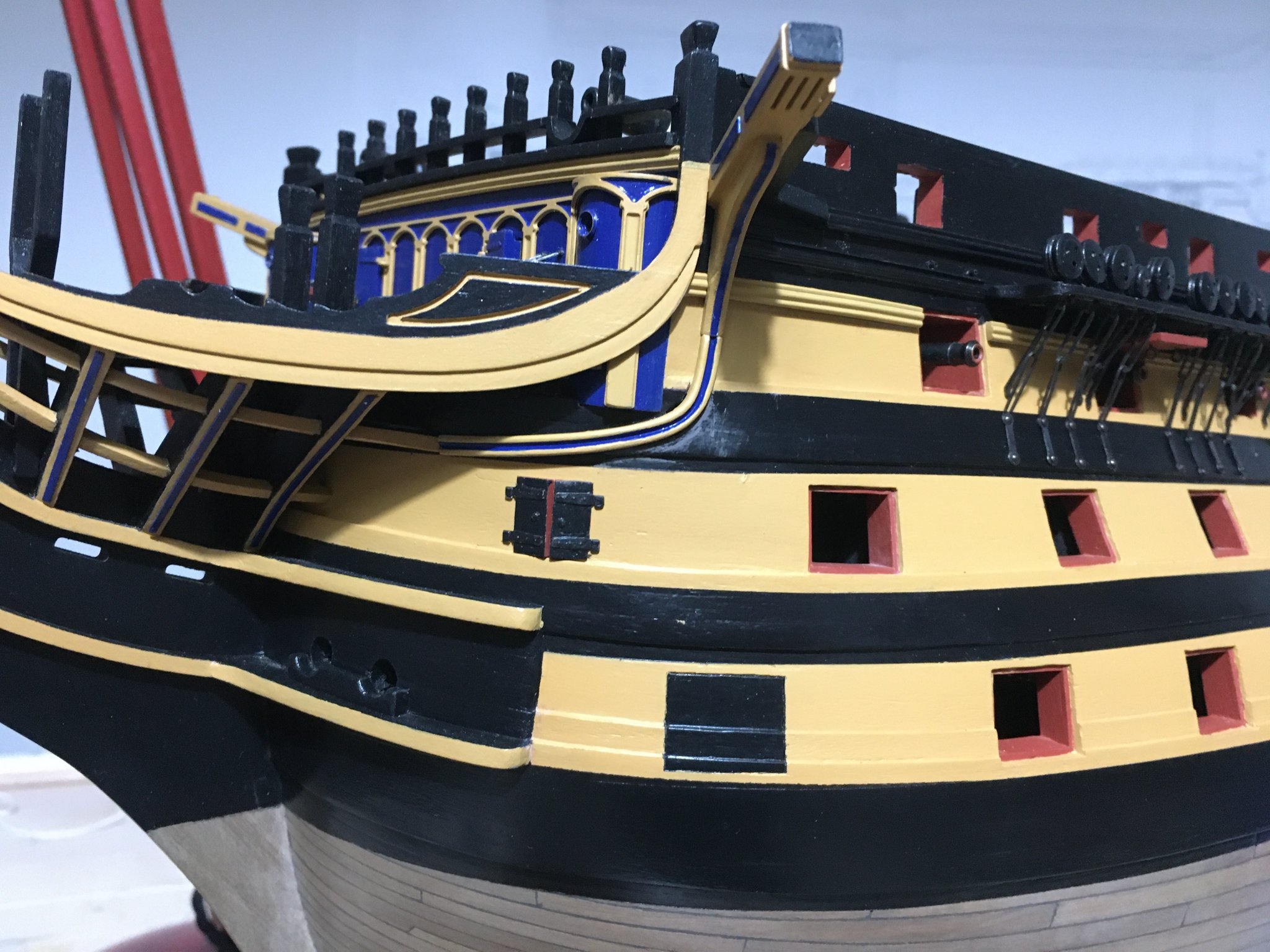
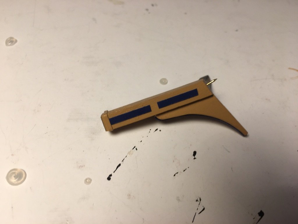
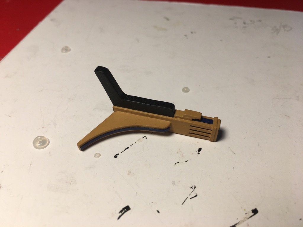
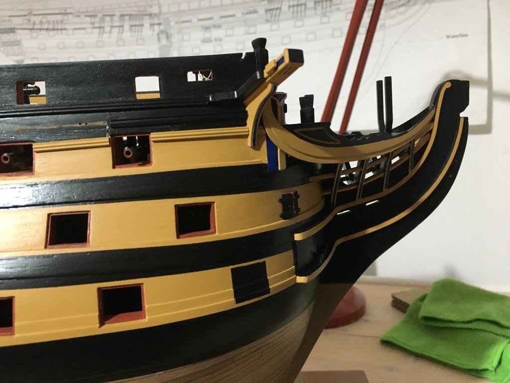
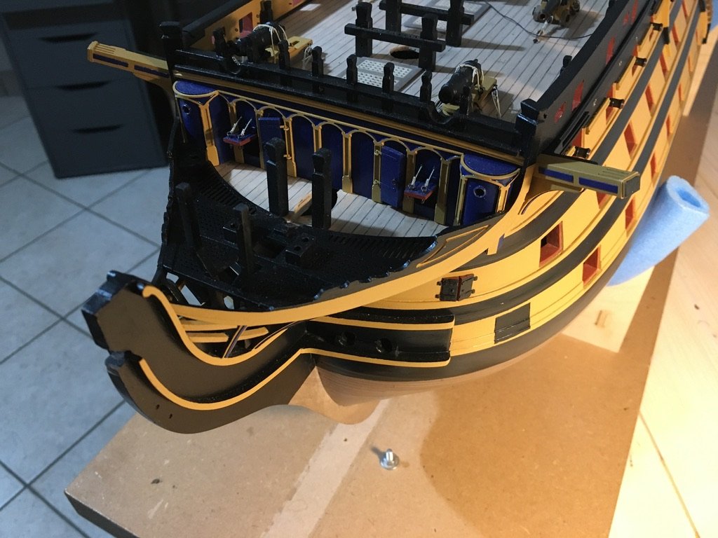
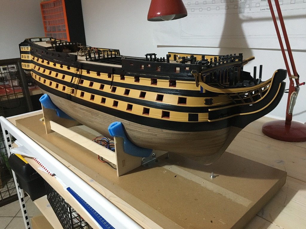
Hi Rick, thank you for your comments. To be honest I haven't yet looked into shapeways web site, but I will definitely do. The photo etched sheets supplied with the caldercraft kit are quite good, I dont mind straying away from the supplied material, in fact I did not finish the bottom of the hull with the copper plates supplied with the kit. I preferred to leave it with the wooden planks showing. Obviously the planking entailed a lot more work to finish it nicely. If I had to copper plate the bottom I could get away with any irregularitie as everything will be covered. You asked me what I think about the now new applied colour on HMS Victory, well, it is being claimed that the aunthentic colour, pink hue, is the actual colour it was during the Battle of Trafalgar. To be honest I see the new pinkish colour a bit odd for such a battle ship. I prefer the previous colour it was painted in, which apparently is described as mustard orange or orange-brown. I stuck to this colour, in 'admirality paints' it is the 'yellow ochre'. I think the question is if either you want your model to look like the colours you were already used to see her in, which in my opinion looks better, or how authentic you want to be and paint it in the pinkish colour it is being claimed is the right one, which colour some people even desribed as hedious. Now for an update for the work I managed to do on my model. Fitted the side entry port steps. As a guide for their alignment I use pieces of tape to avoid pencil marks on the painted surface. Also painted the Cat Heads. I will glue on the cast crowns at a later stage to avoid scratching them while doing other work. The band is made from 0.25 x 1.00mm polystyrene strip. Fitted and paintred the remaing brass rails on the hull sides. Did some retouching on the already fitted rails. The paint chips so easily from on brass!!! Finished the blue trimmings on the edges of the head timbers. I made them from strips of Polystyrene 0.25 x 1.0mm. I cut them to the required lengths, paint them and when dry glue them in place. Robert
- 527 replies
-
- 14
-
-
- caldercraft
- victory
- (and 1 more)