HOLIDAY DONATION DRIVE - SUPPORT MSW - DO YOUR PART TO KEEP THIS GREAT FORUM GOING! (Only 24 donations so far out of 49,000 members - C'mon guys!)
×

Robert29
-
Posts
417 -
Joined
-
Last visited
Content Type
Profiles
Forums
Gallery
Events
Everything posted by Robert29
-
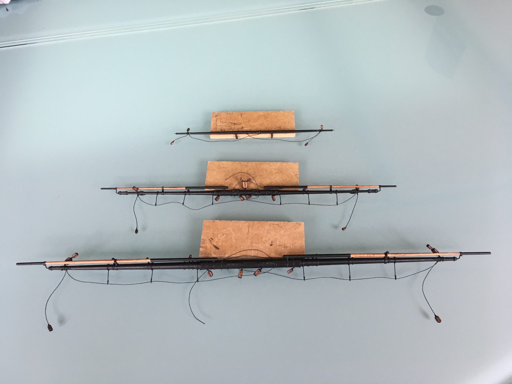
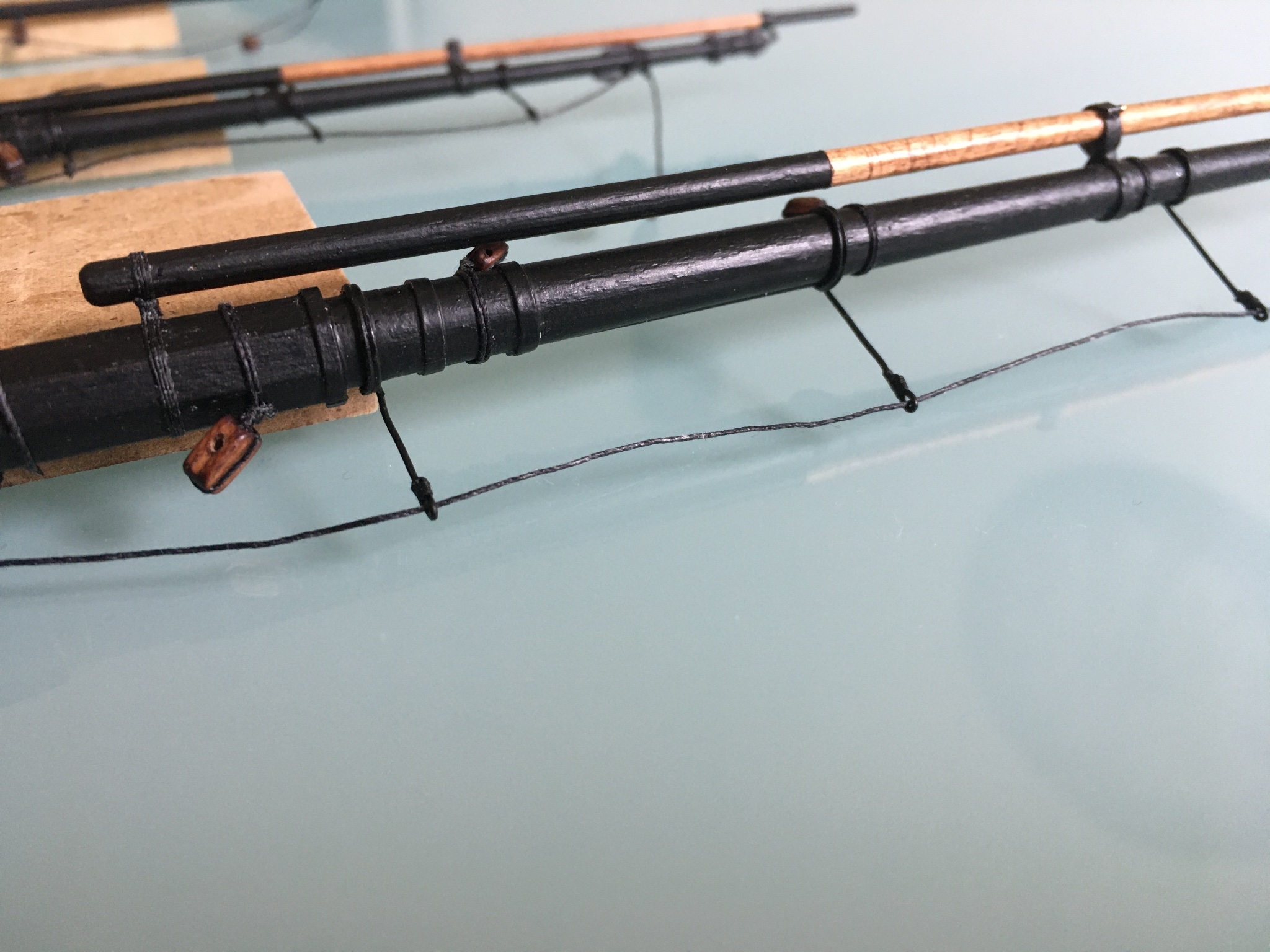
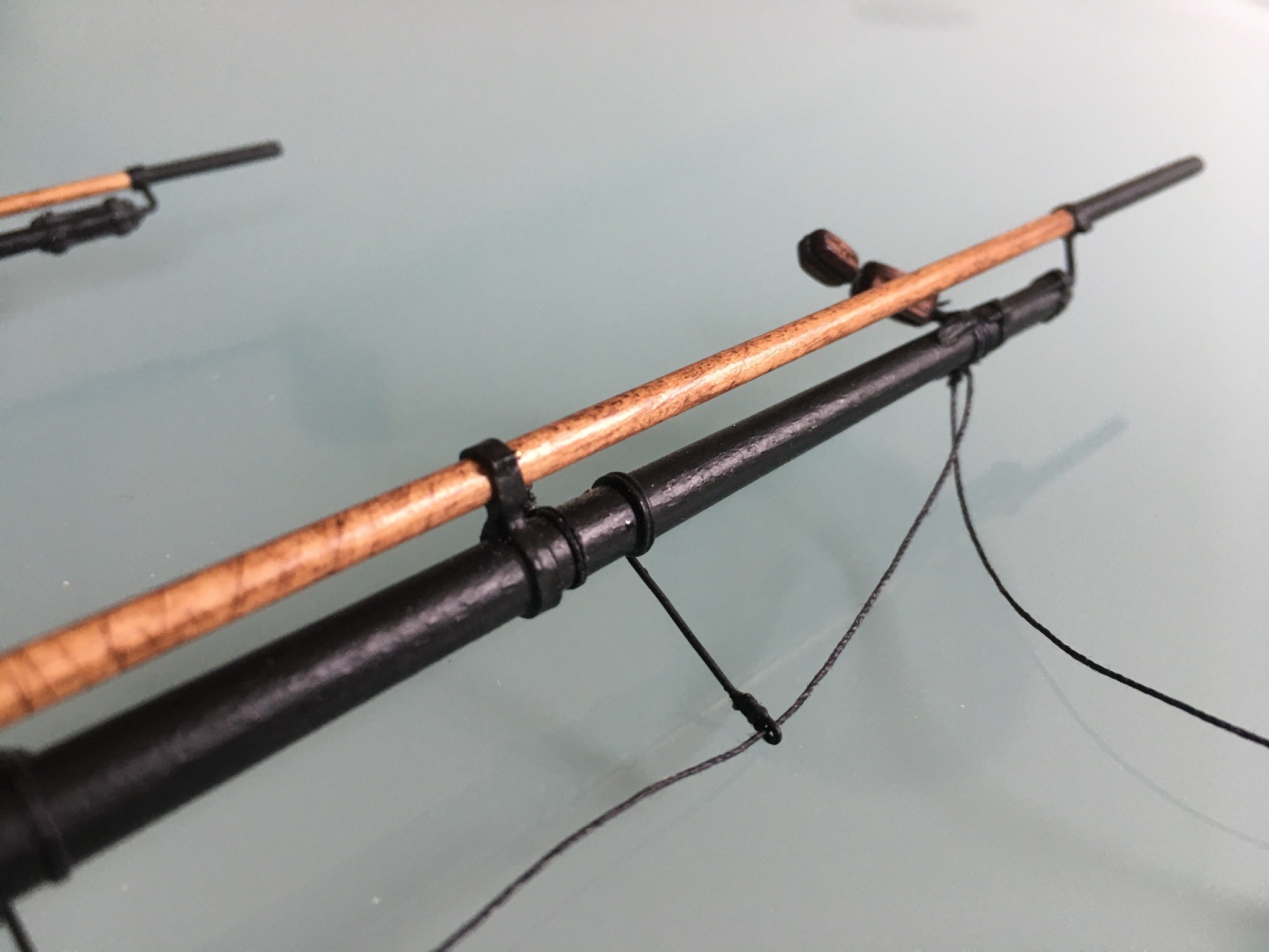
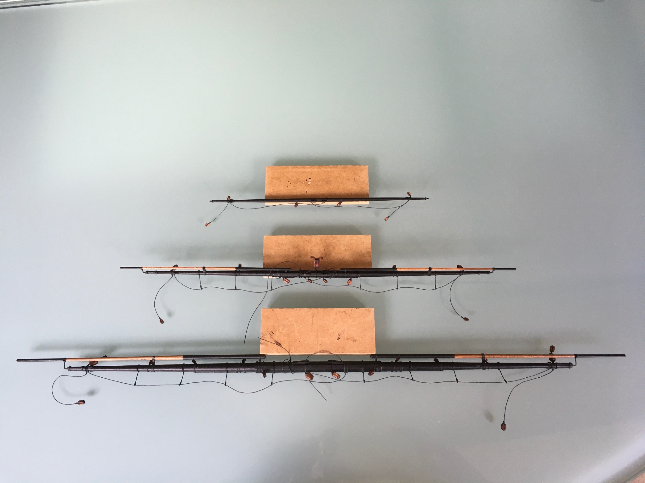
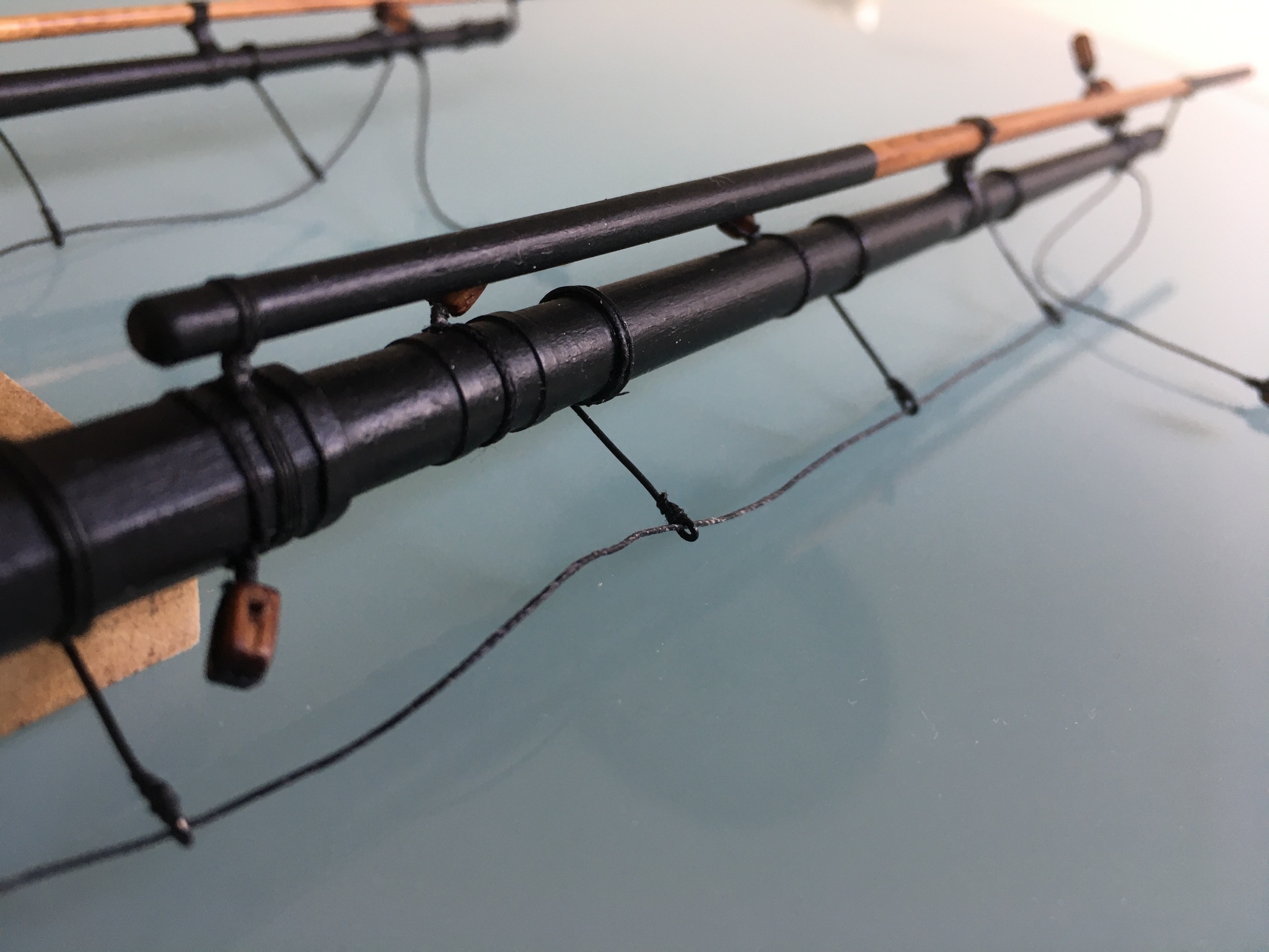
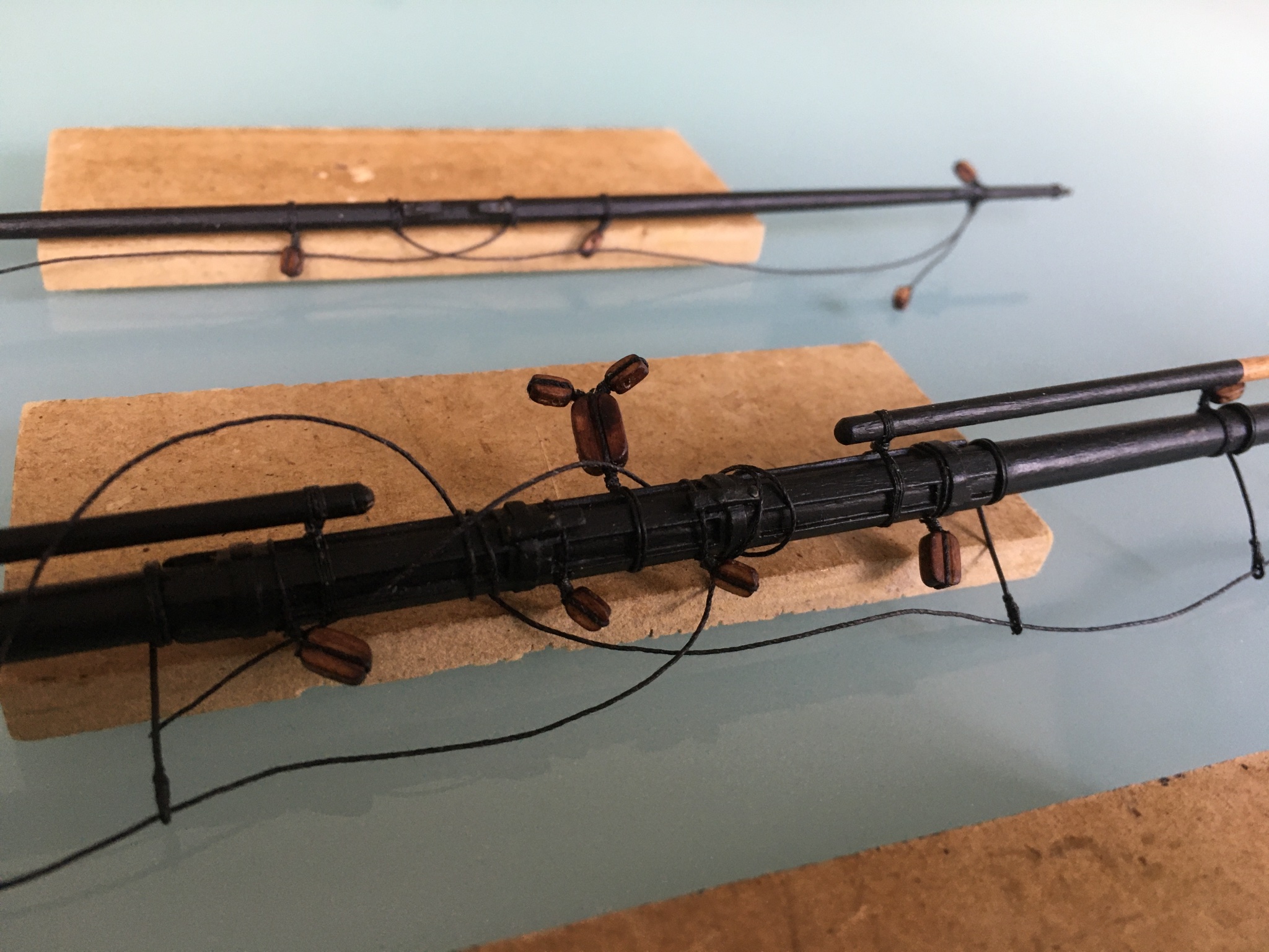
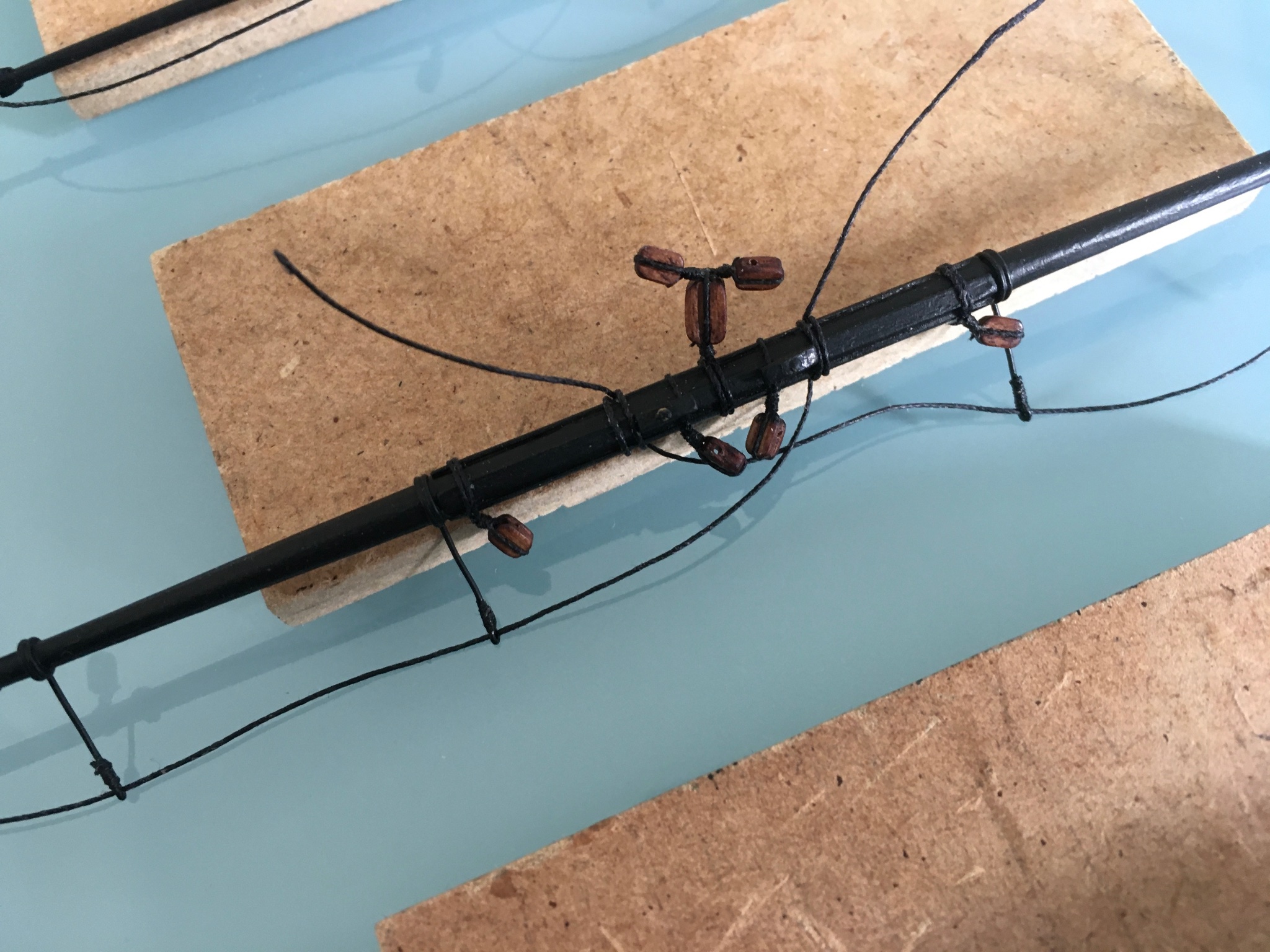
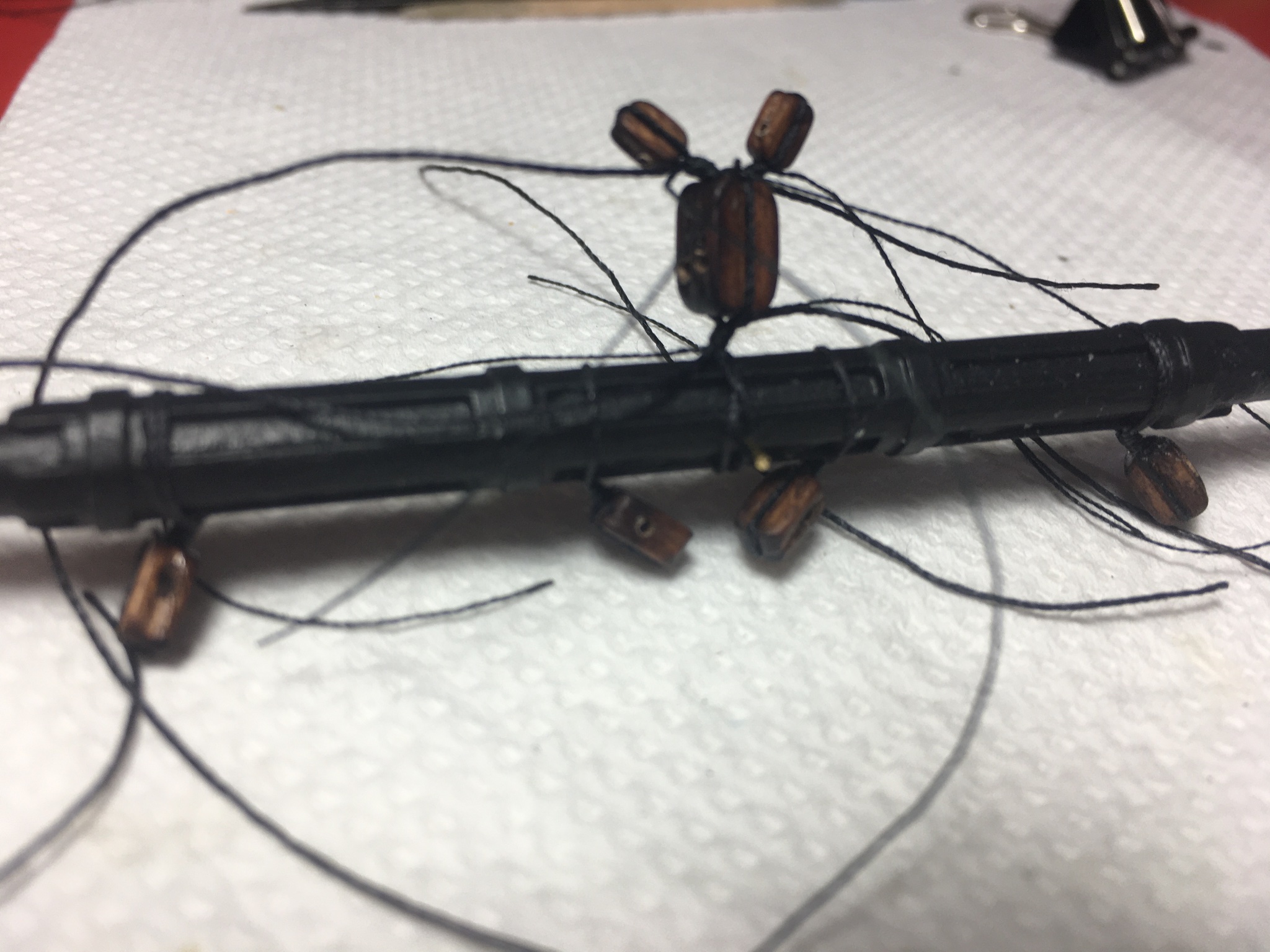
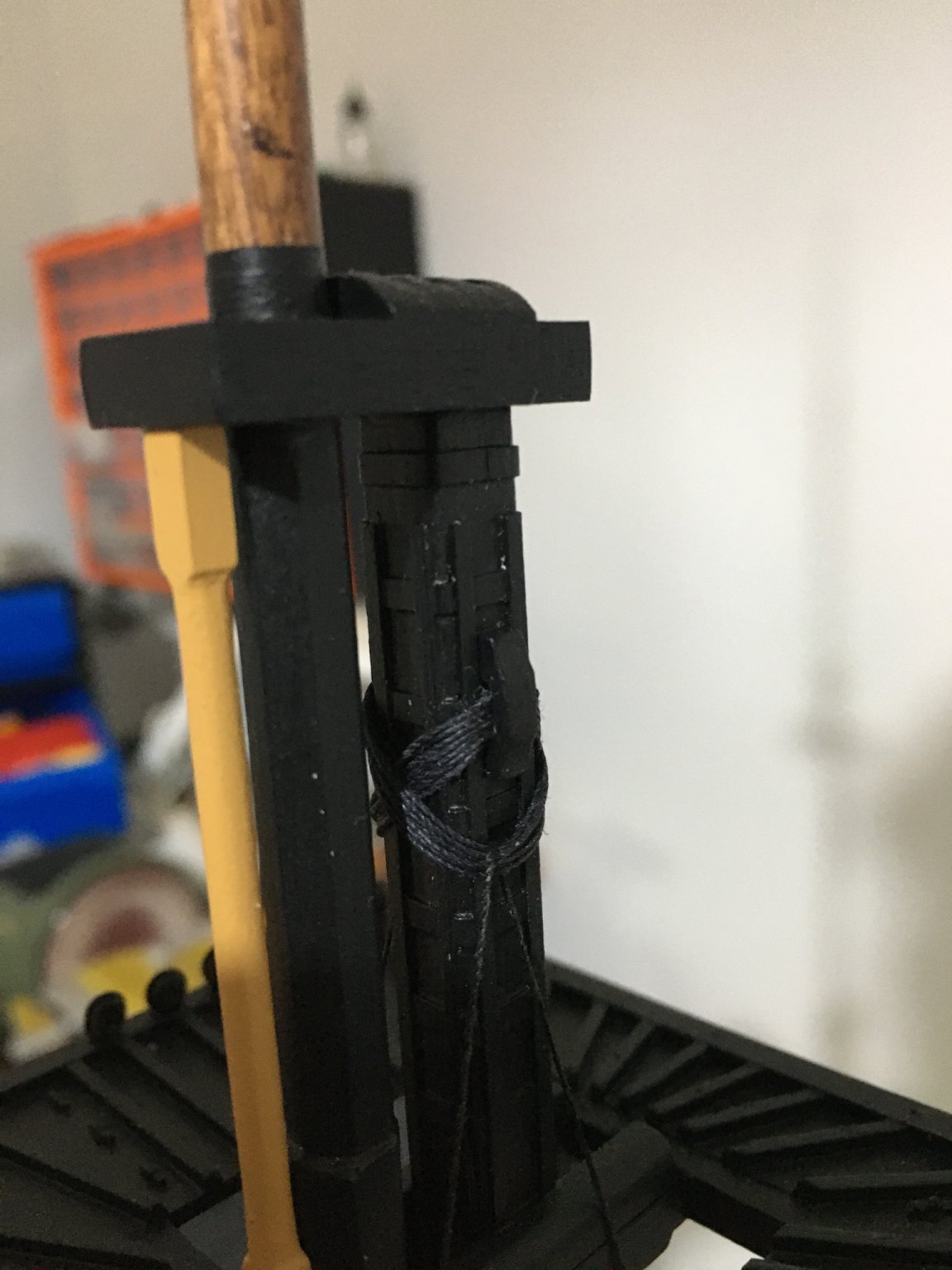
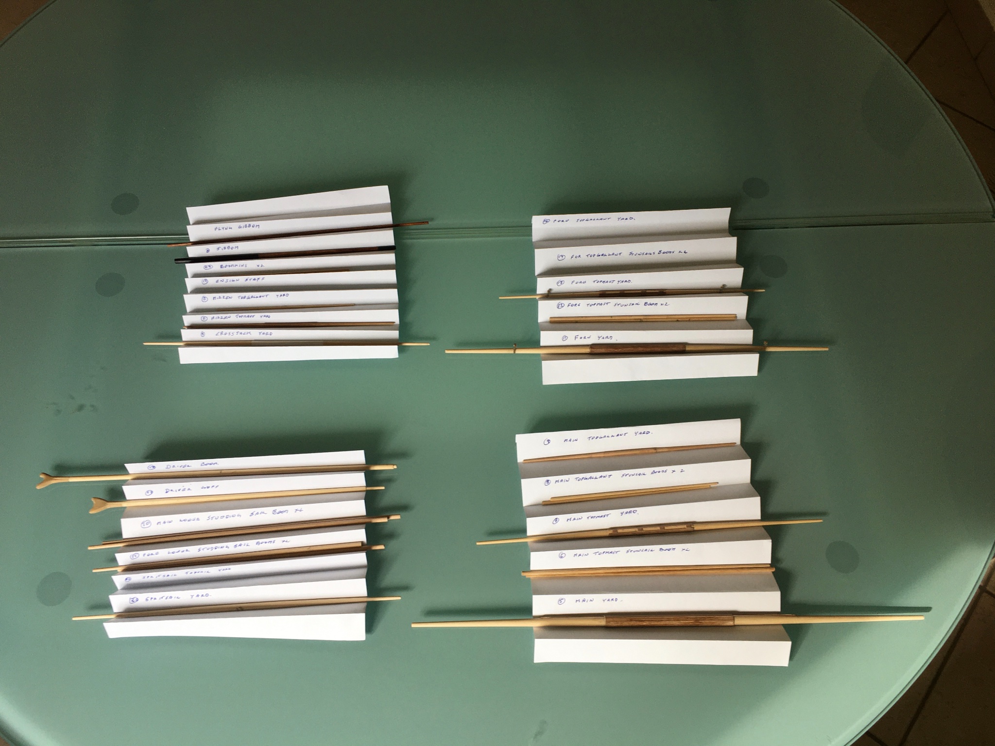
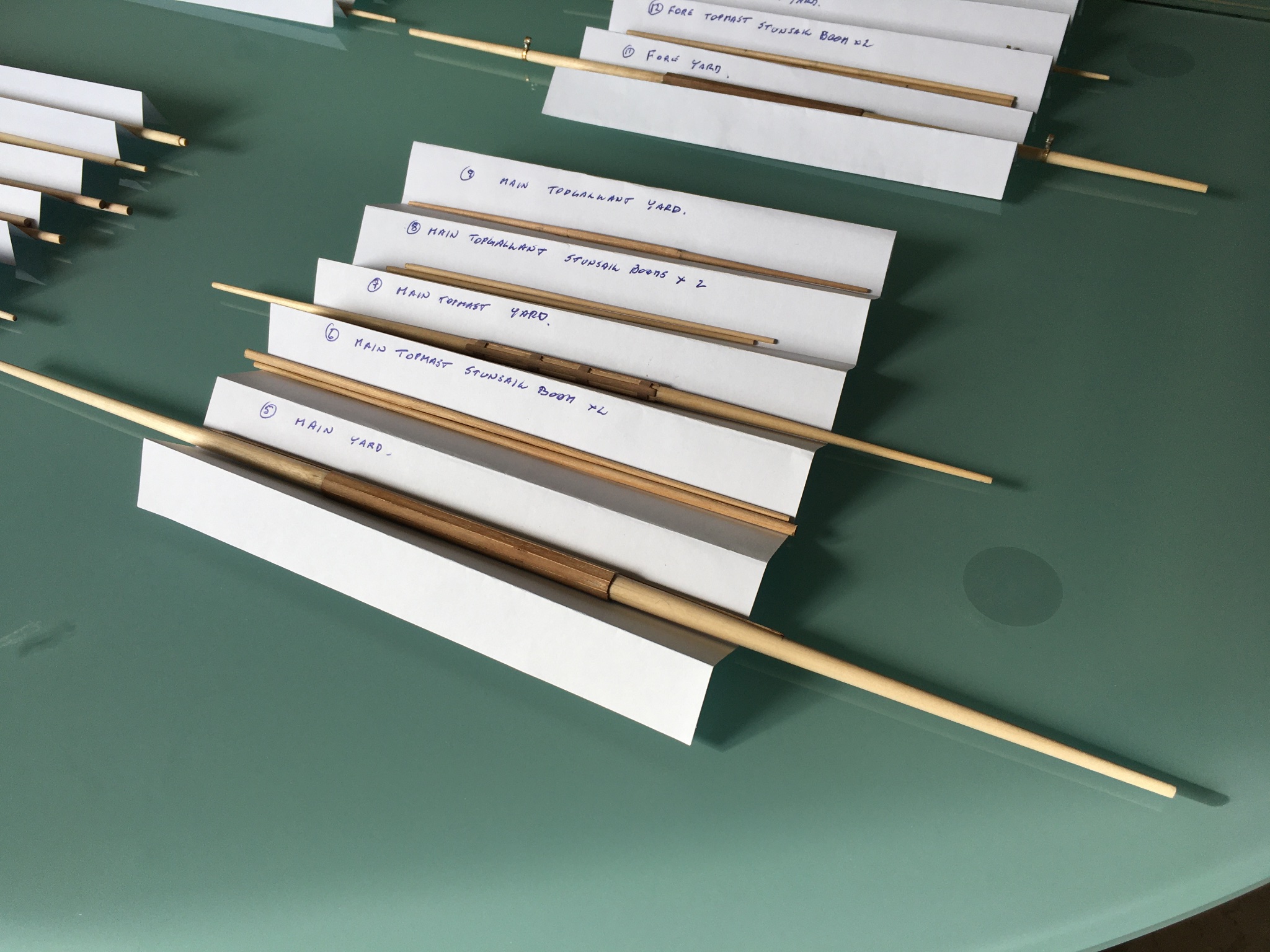
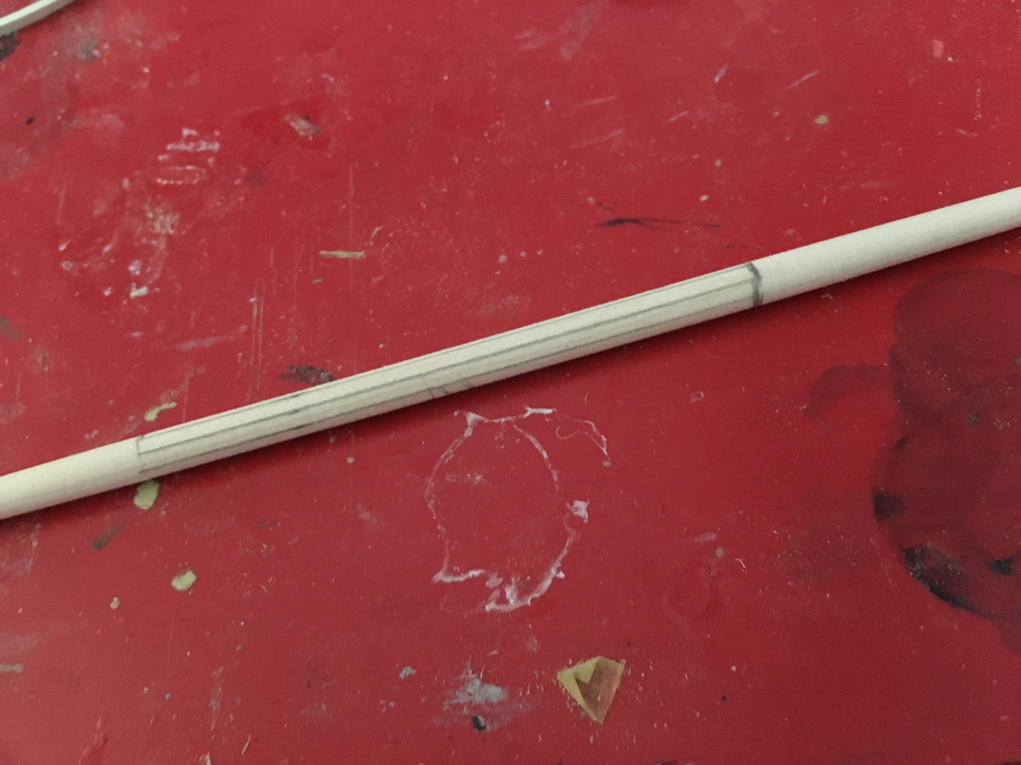
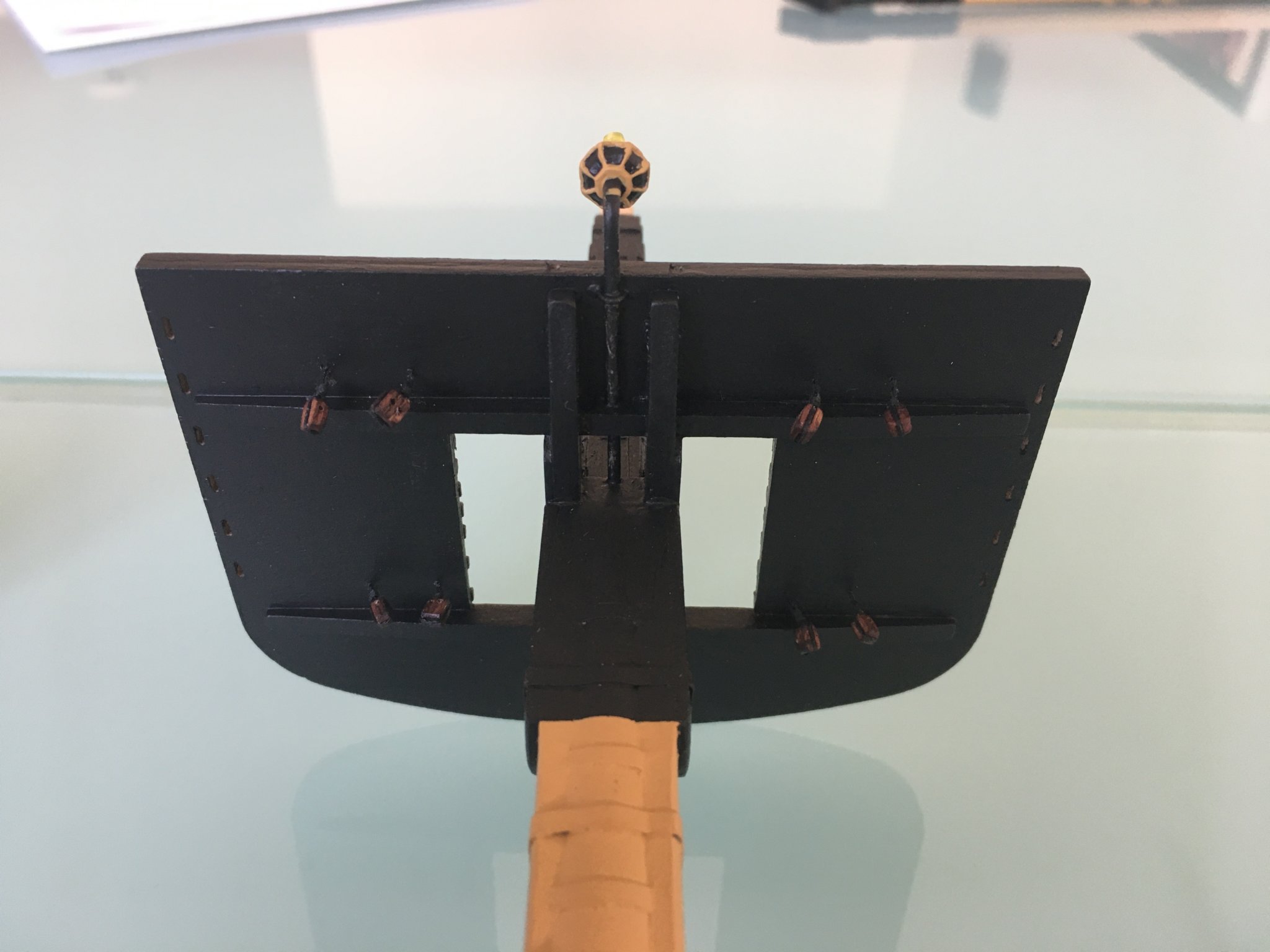
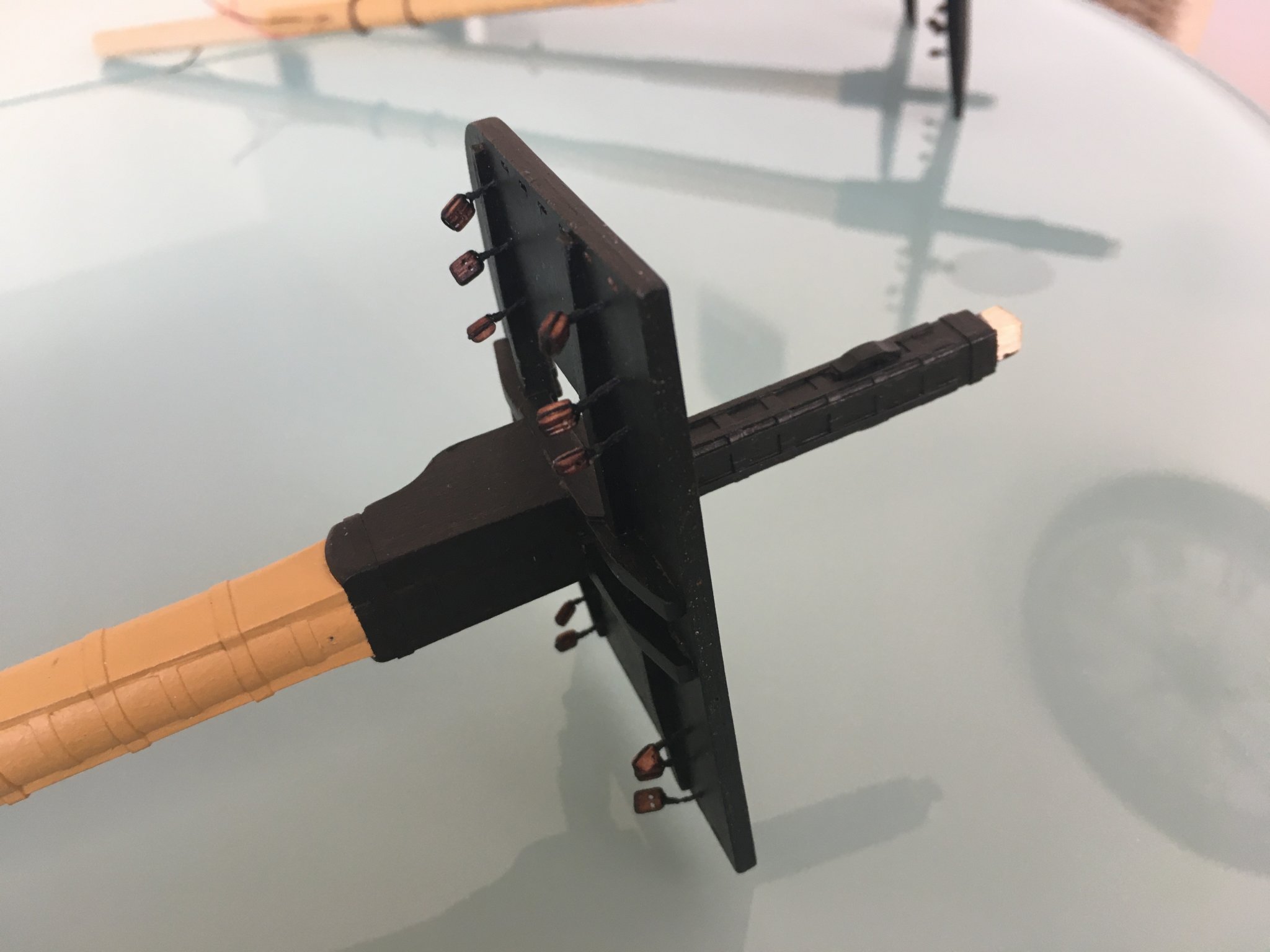
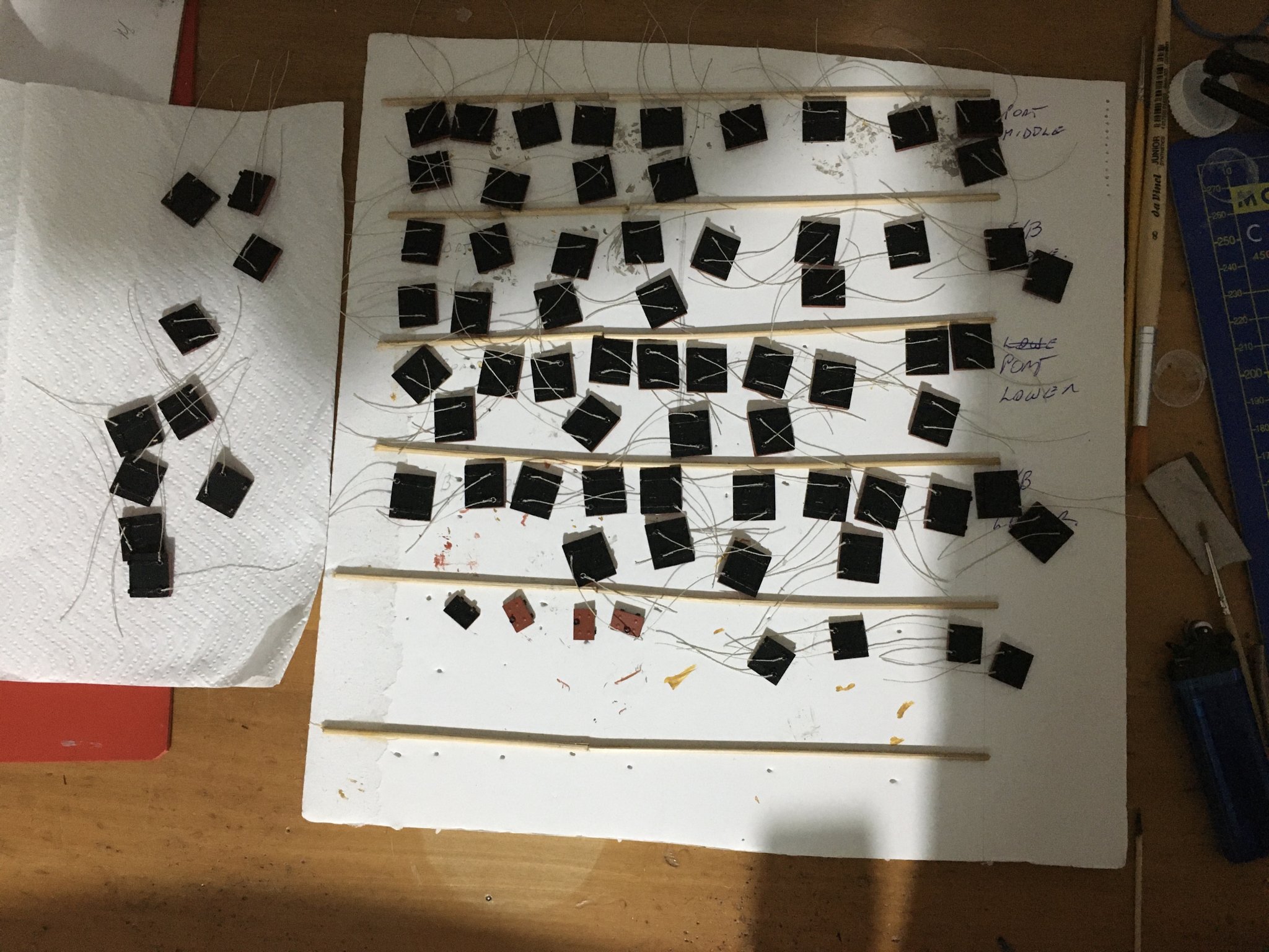
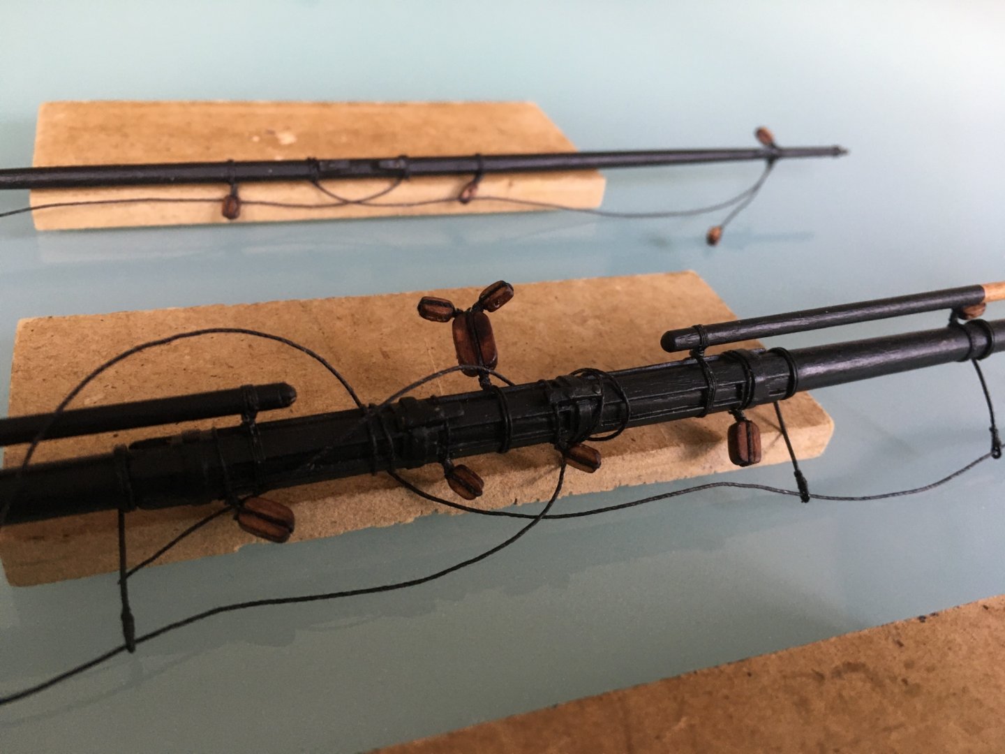
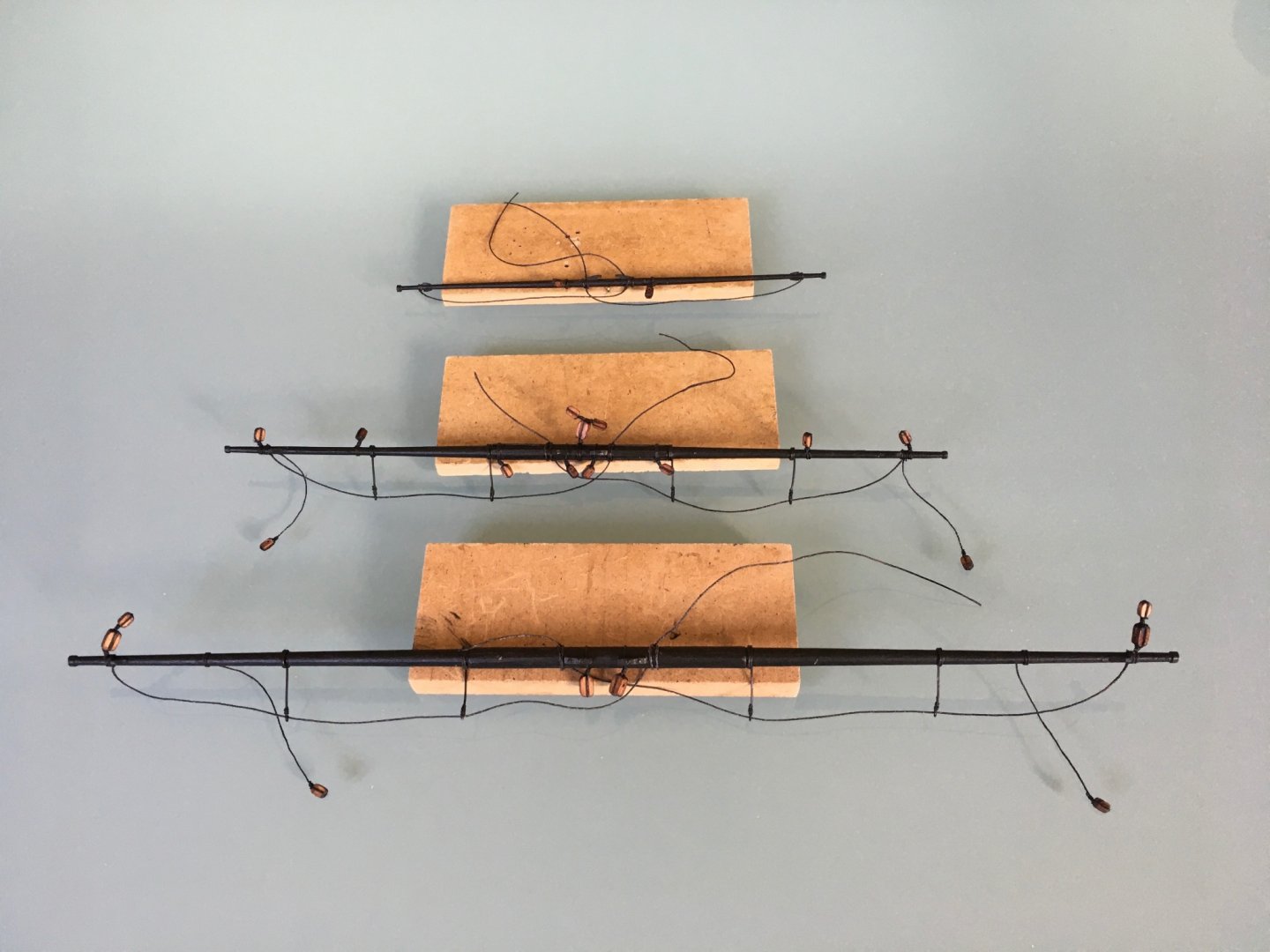
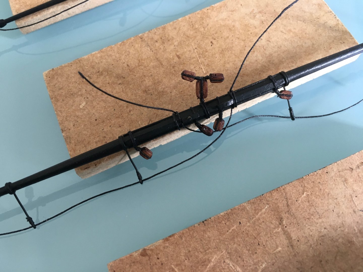
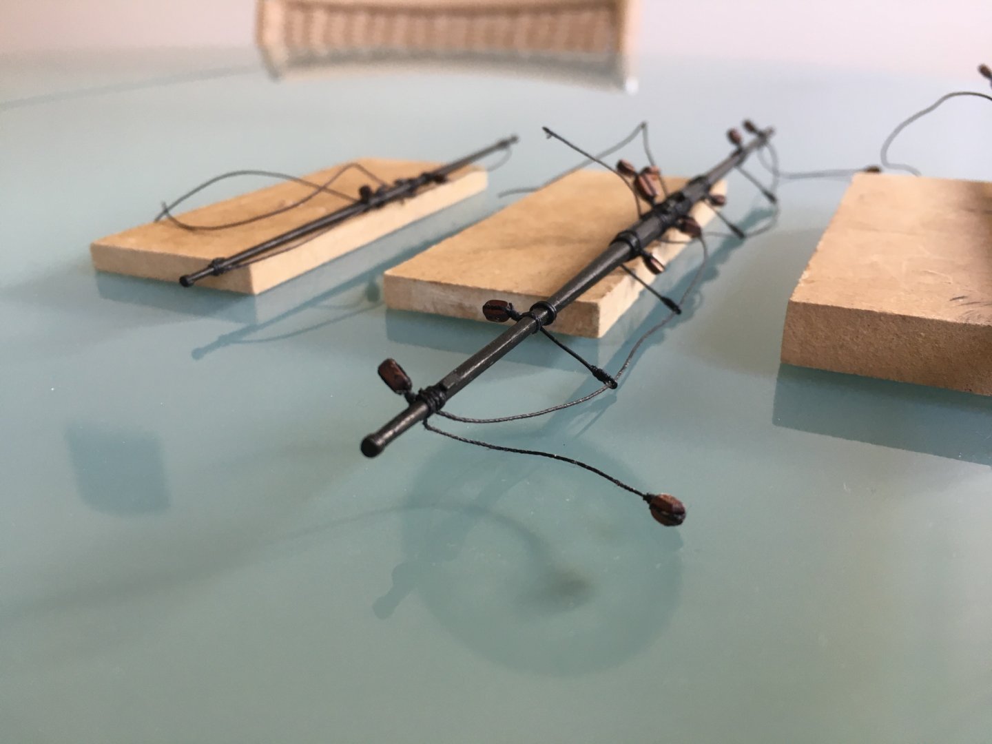
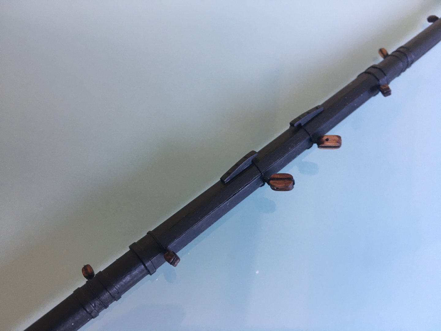
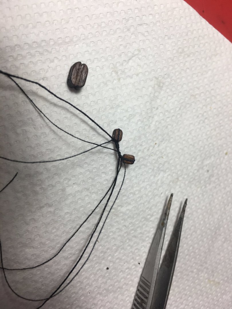
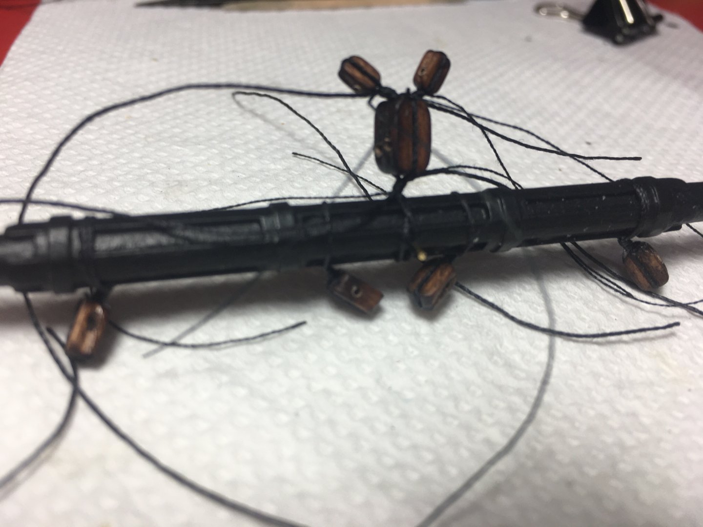
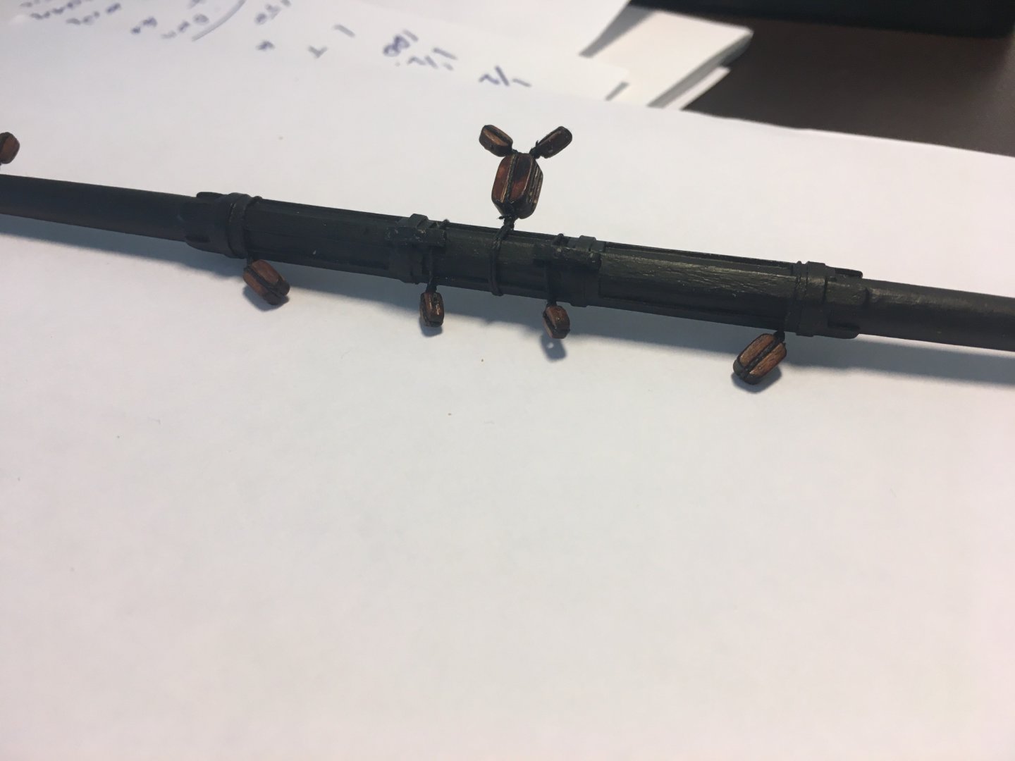
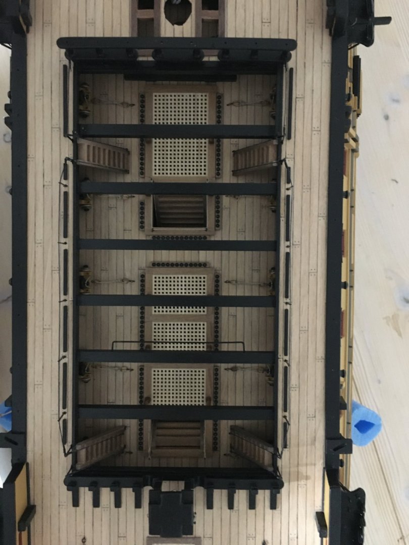
 I painted all the yards, stunsail booms, gaffs, etc and rigged all the blocks, pendants and stirrups that have to go on the yards, hoping I did not miss any because it would be more difficult to rig them when the yards are in place. I also fitted the horses but as you can see from the photos they are not adjusted correctly. The outer end of the horse is tied to the yard accordingly, passed through the eyes of the stirrups, but the inner end I left loose around the yard. I will adjust these to the correct position with a sagging effect and tie properly the end of the horse just before I fit the yards in place. I made the stirrups from 0.5mm black coated copper wire I already had. It had a shiny look so I painted them mat black. I was thinking of making them from thread, but I think it would be a bit difficult for them and the horses to keep the right shape. Blocks rigged to yard before fitting the stunsail booms to the yards. Rigging the two buntline blocks and the tye block that go in the centre of the topmast yard. Foremast Yards Mainmast Yards Mizzenmast Yards Now, that I know that I have the yards ready when I come to them I have to concentrate on the wok that still has to be done on deck and on the hull before I start the rigging, such as the fire buckets and the hammock crane nettings. I have ordered some very small decals of the monogram that goes on the fire buckets. But unfortunately it is taking some time. Robert


- 527 replies
-
- 11
-

-
- caldercraft
- victory
- (and 1 more)
-
Beautiful work as always Heinz. Amasing craftsmanship. They are photos that I go over so many times and admire the fine details you bring out. Best wished for the coming year and Happy Christmas to you too Heinz. Robert
-
Hi MD, Thank you for taking the time to source an answer for my question. The images are very informative. I think you are right, it could be a combination of both. Robert
-
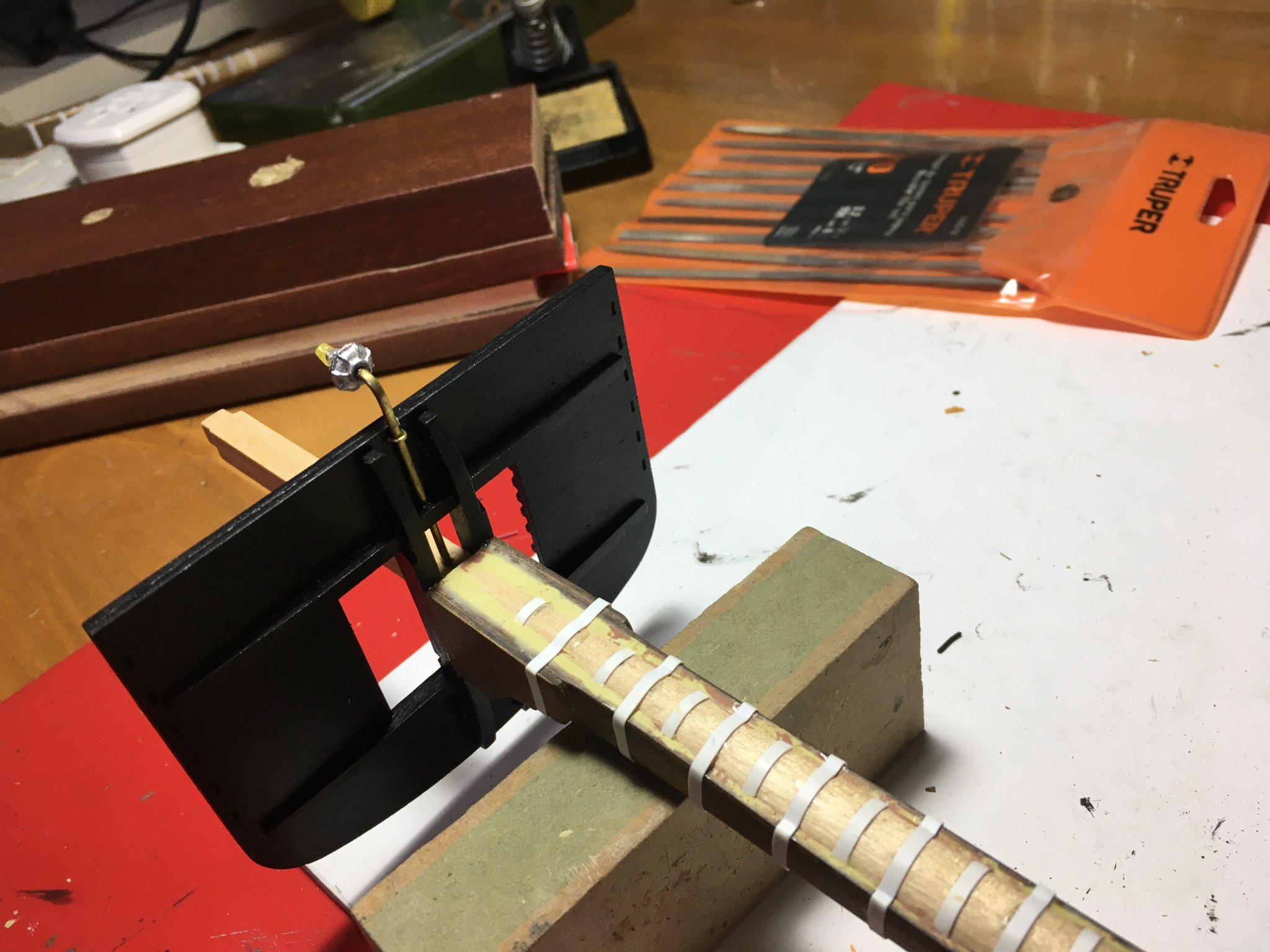
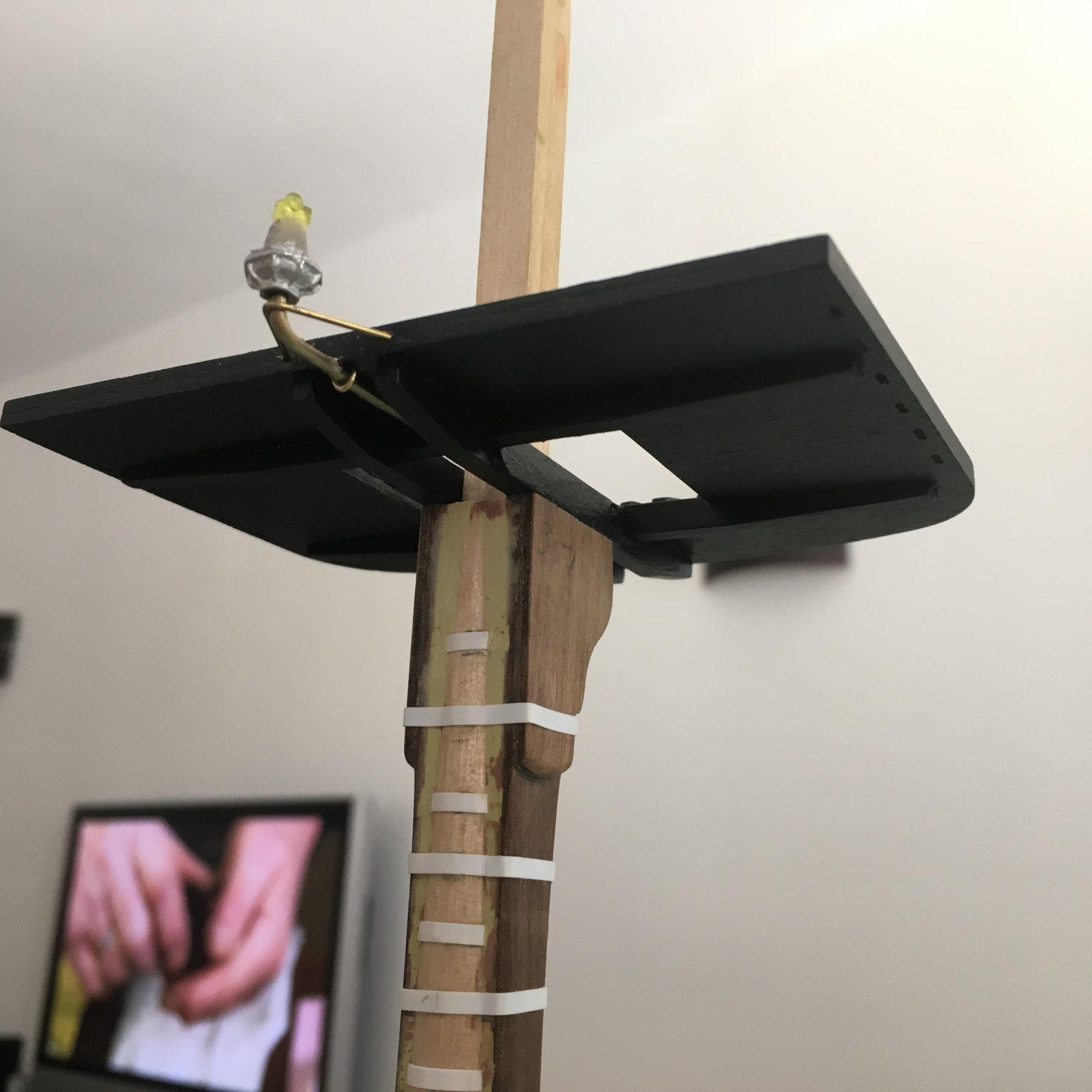
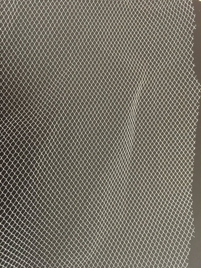
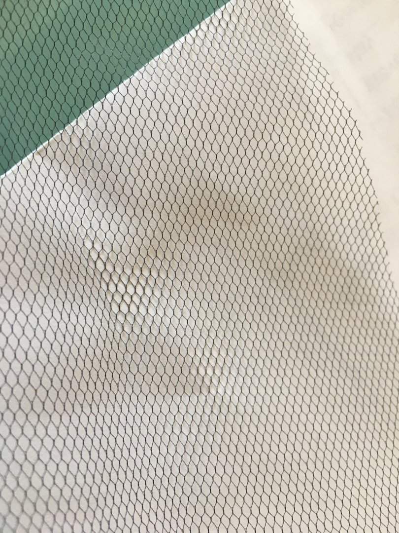
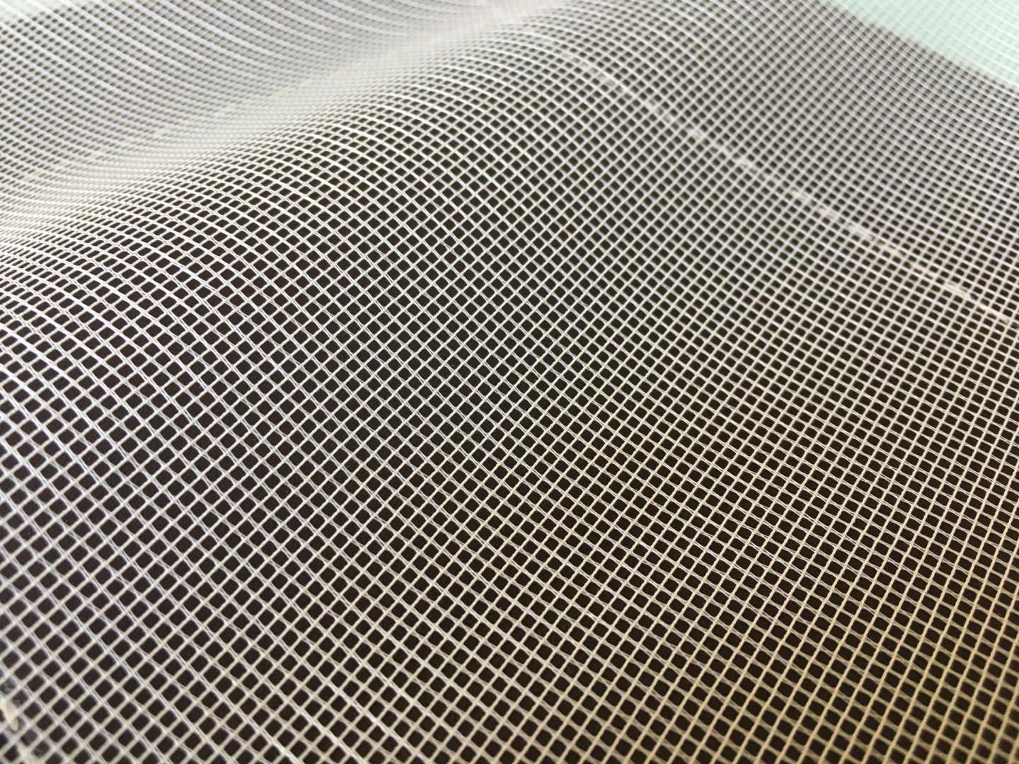
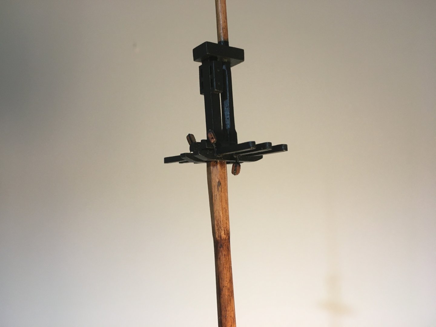
I have a small question. As I am in the process of preparing the yards etc, when I came to the Jackstaff and the flag pole I was wondering if at the top they had a block or a sheave to hoist up the flag. Anybody has the answer for this please? I tried to look it up, but still not sure what was used. As I also soon have to do the hammock cranes I bought some tulle, I could only find nylon. I thought it looked quite unrealistic. Then from a drapery store I found this. Although it is made from polyester it can take some dying. I tried it with tea. I think it looks better. The left part is dyed and the right part is as is. Robert

- 527 replies
-
- 3
-
-
- caldercraft
- victory
- (and 1 more)
-
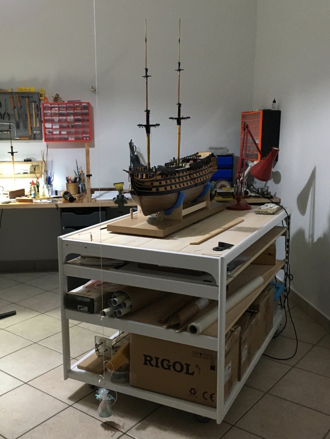
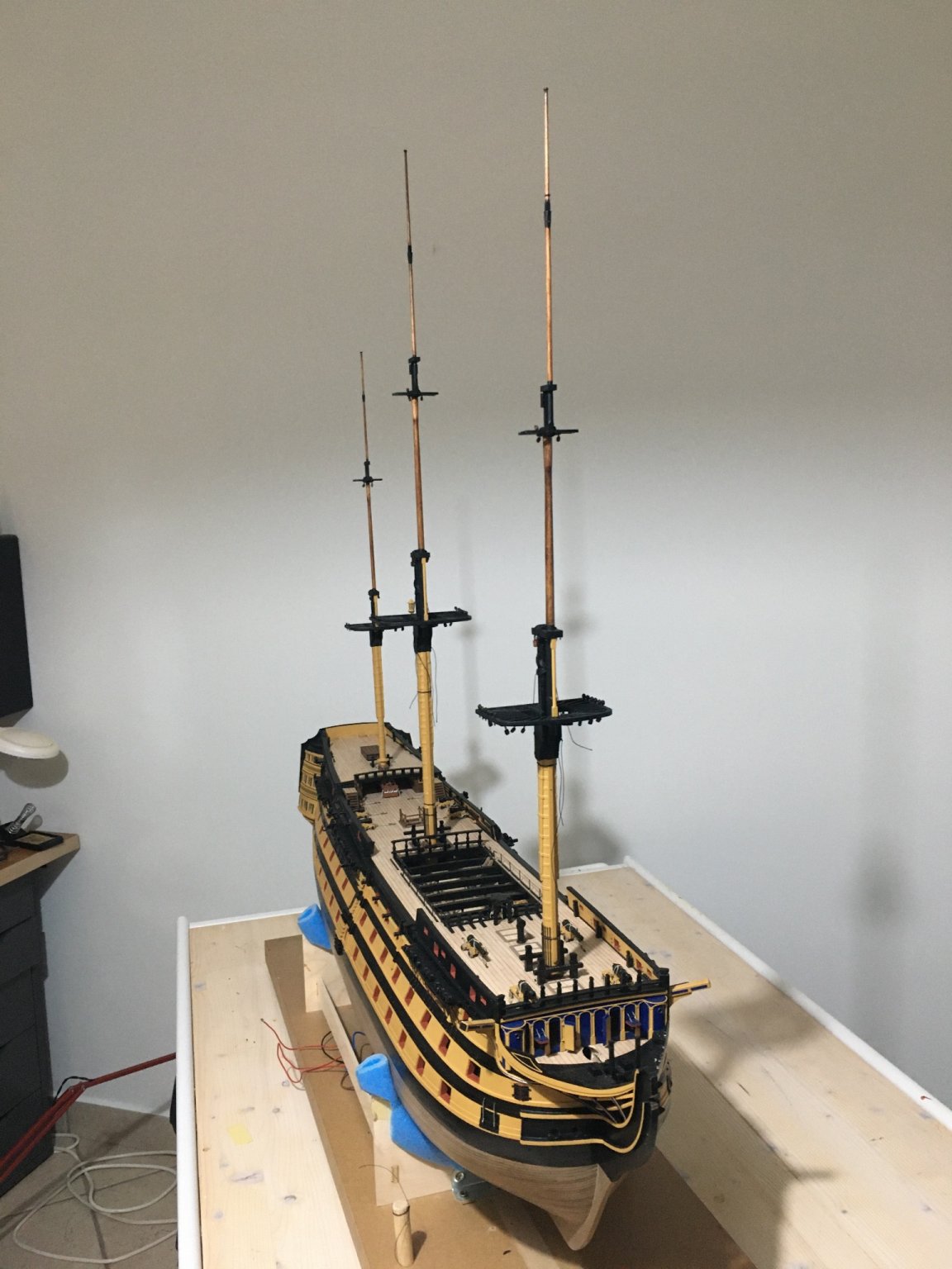
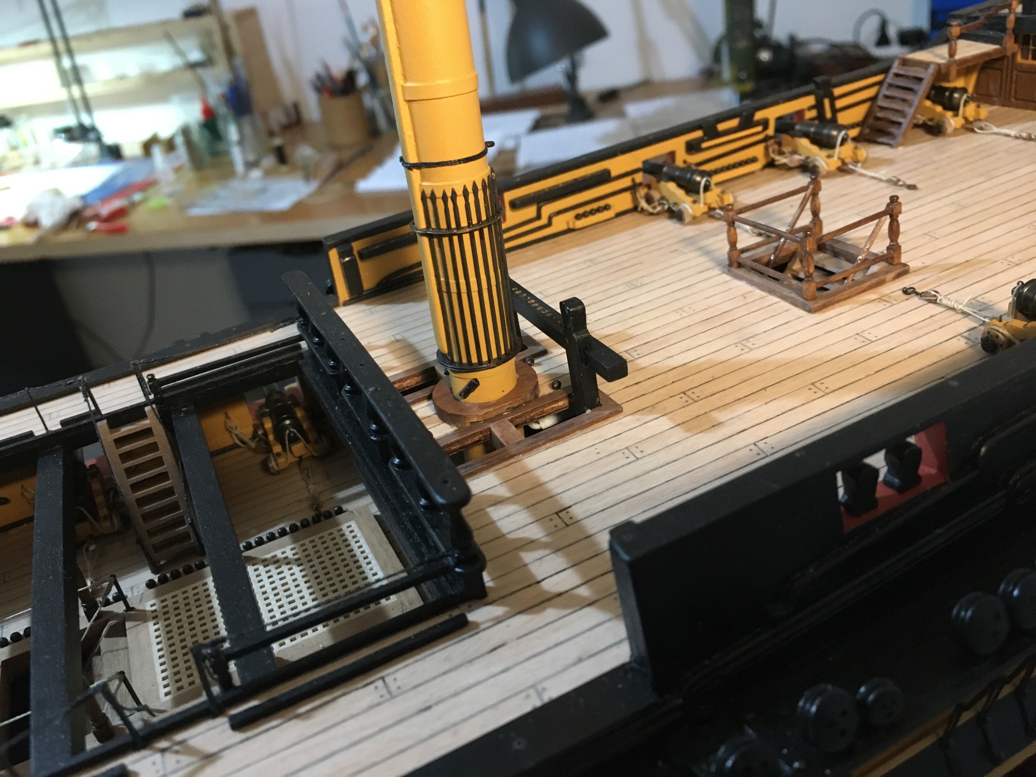
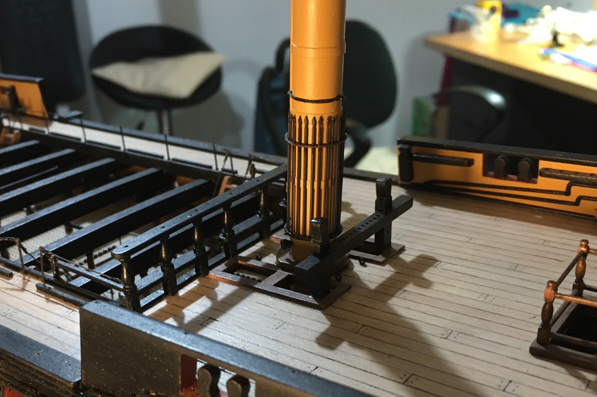
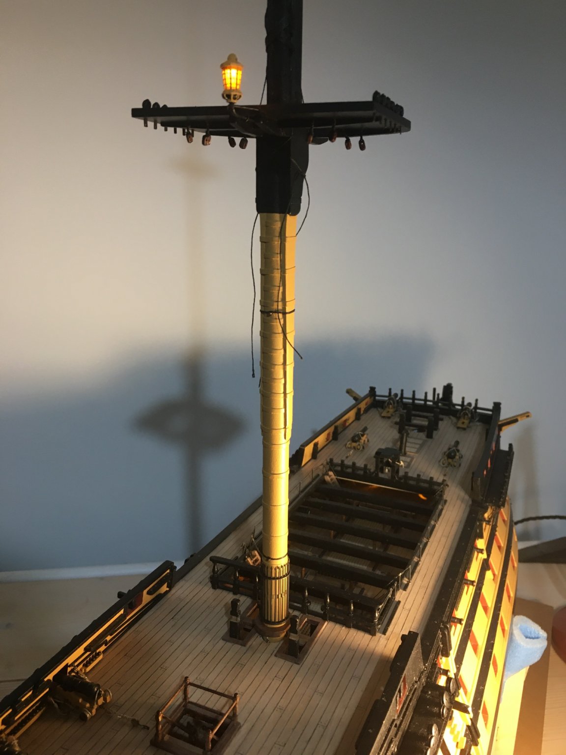
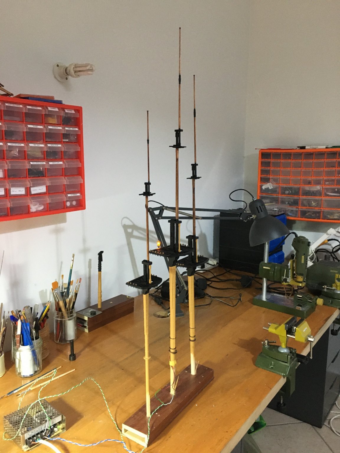
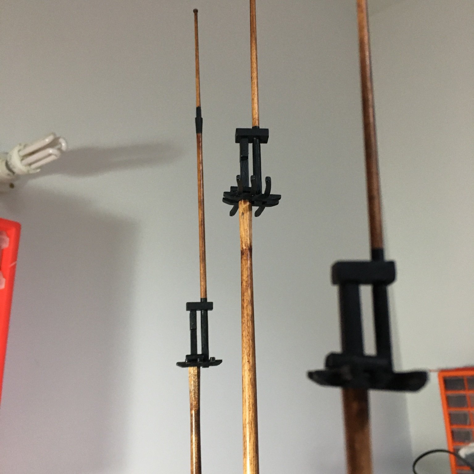
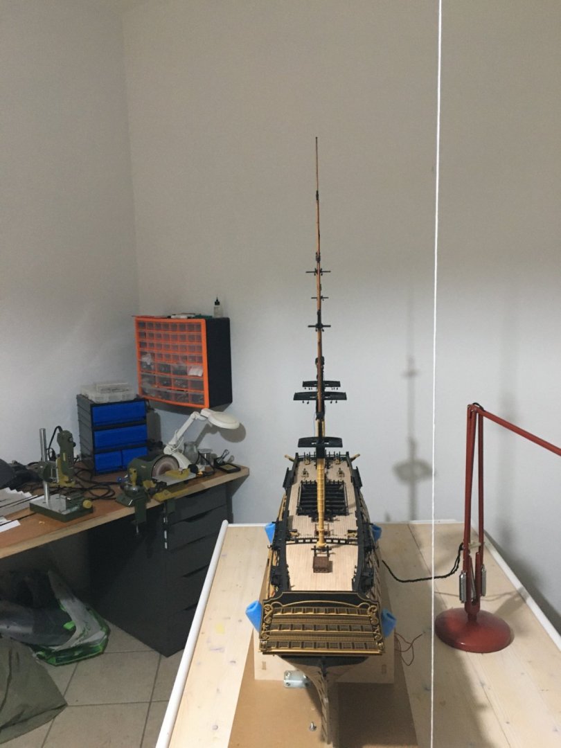
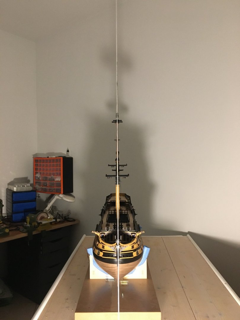
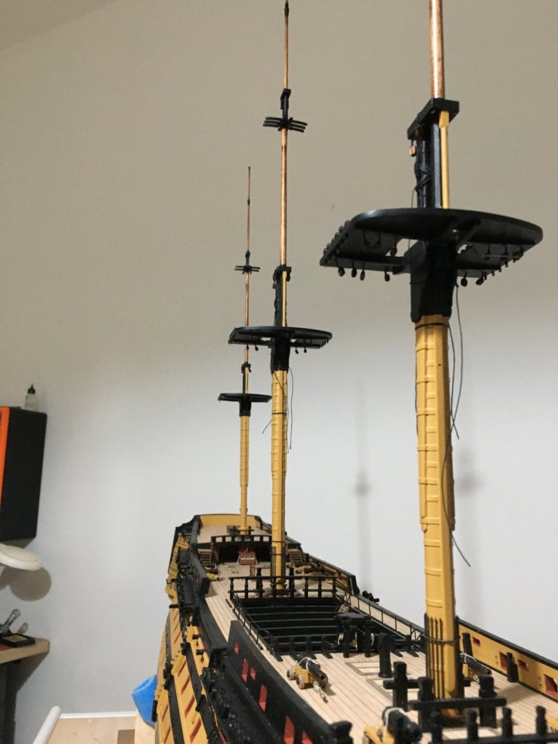
Thank you Martin. All three masts up. To align the three masts I tied a string to the ceiling with a weight at the lower end. From the bow, masts in line with the string and with each other. From the stern. The three masts in line with each other. Sleeve for the main mast pushed down in place and glued. For the fore and mizzen masts I dropped some glue inside the holes, to go down the very bottom, pushed in the masts and glued the sleeve to the deck and mast together. I used white glue all the way to give me time to adjust align the masts. Robert


- 527 replies
-
- 11
-
-
- caldercraft
- victory
- (and 1 more)
-
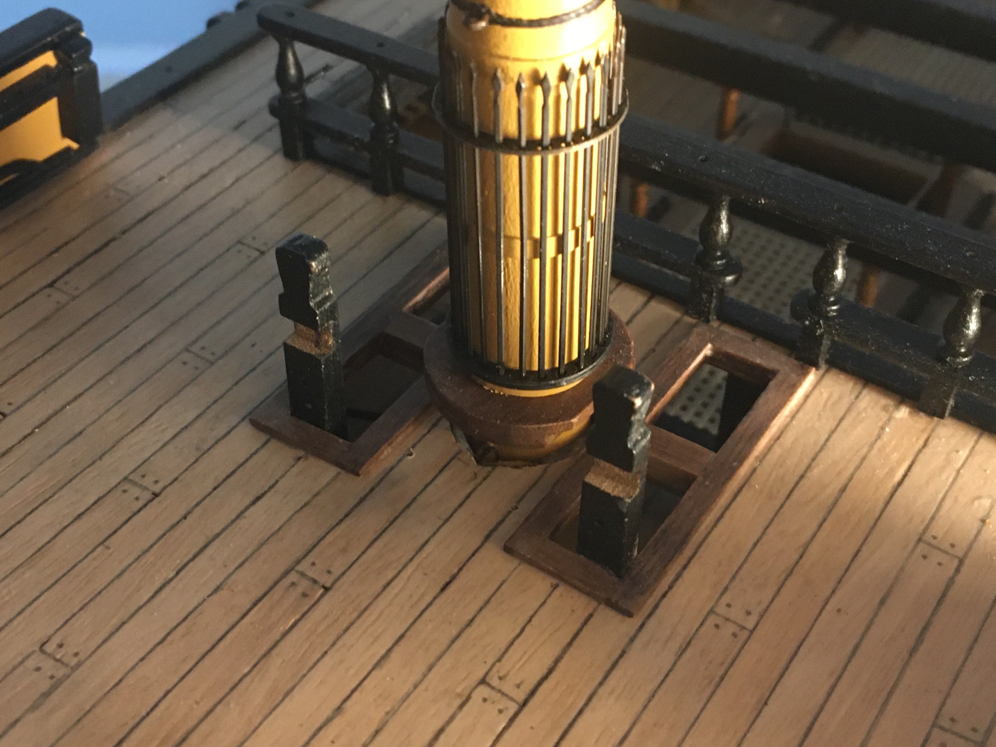
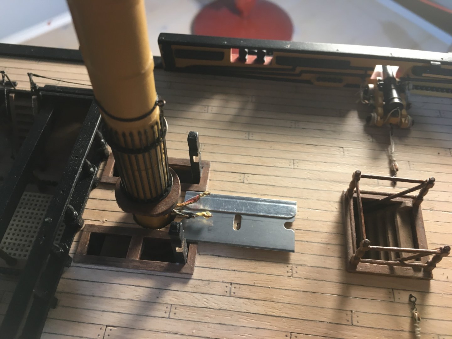
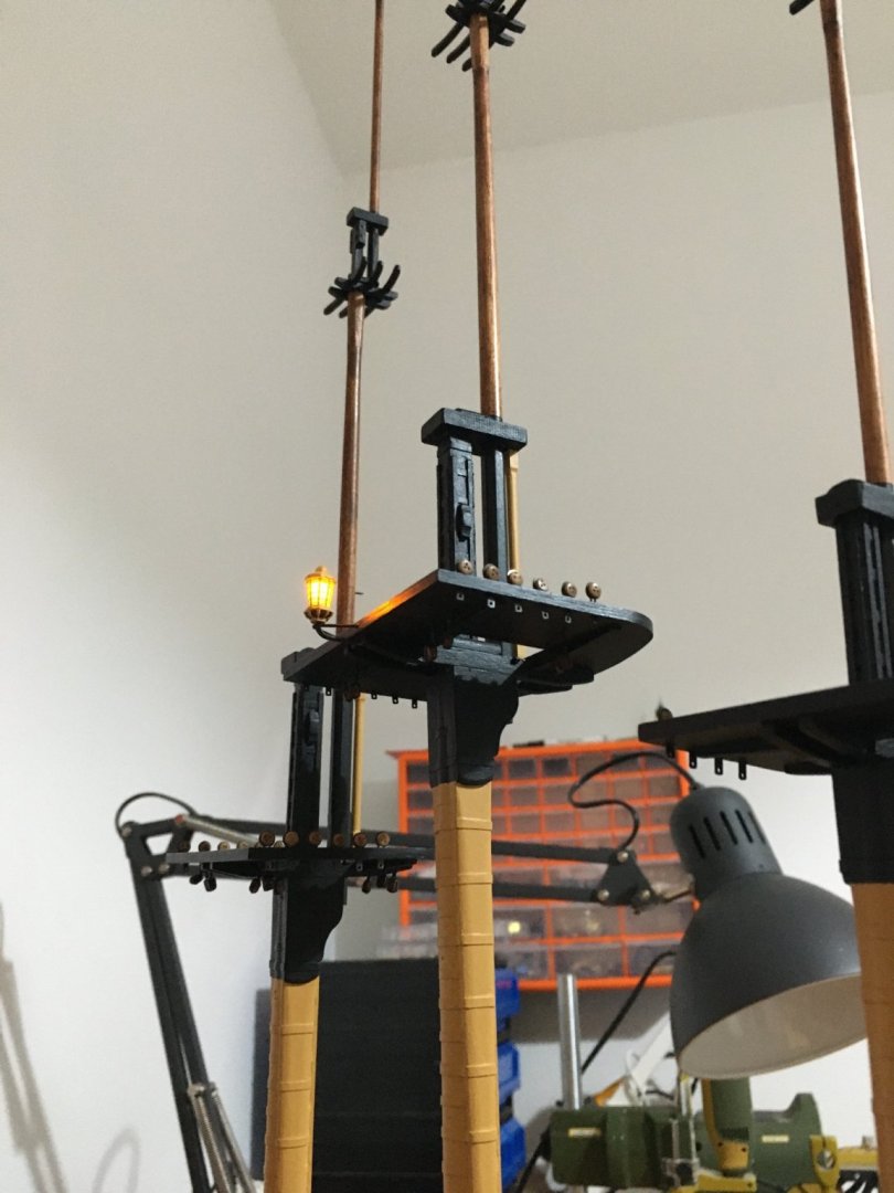
Thank you all for the likes. A small update. I was working on the yards but ran out of black paint, actually what I had left had quite a few solid pieces in it, so I decided not to use it and order new paint. Whilst waiting fort the paint I thought I might as well continue work on the masts. I fitted all the blocks and eyelets on the masts that I could, for the reason the it is much easier when the masts are still in hand. I left out the blocks that a line has to be attached to. I think it is better to rig them later on, complete with the line and eyelet attached and glue the eyelet in place when times come for its rigging. I just prepared the holes on the masts for the eyelets. I had forgotten to make the boom saddle on the mizzen mast. Blocks rigged to the cap on the main mast. Blocks rigged to the main topmast top. I decided it's time to start fitting the masts in place. I was dreading to fixing the main mast because of the lantern wire connections, so I started with it so that I would not have the other two in the way since I had to solder and so on. Since the mast goes through two other decks, apart from the upper deck and the slot in the keel, it was very sturdy when slid in place and did not really need any gluing. I cut the wires as short as possible, leaving enough length to enable me to solder them and widened the hole in the deck. Slid the sleeve as far up as I could, slid the mast in, leaving it a few millimetres up and soldered the wires from the mast to the ones coming out from under the deck. Pushed the mast all the way down and tucked the wire connections in the space between the mast and the deck. Checked that all is well with the connections and lantern lights up. The sleeve will be pushed down in place and glued and it will cover all the gap and wire connections. I am not gluing it in place until I have the other two masts in place and all three perfectly lined. So basically I have all the wiring ready except for the three lanterns at the stern, but those will come at a much later time because if I fit them now I am sure I will nock them down quite a few times while rigging. I will soon post some more photos when I have the other two masts in place and lined. Robert


- 527 replies
-
- 7
-
-
- caldercraft
- victory
- (and 1 more)
-
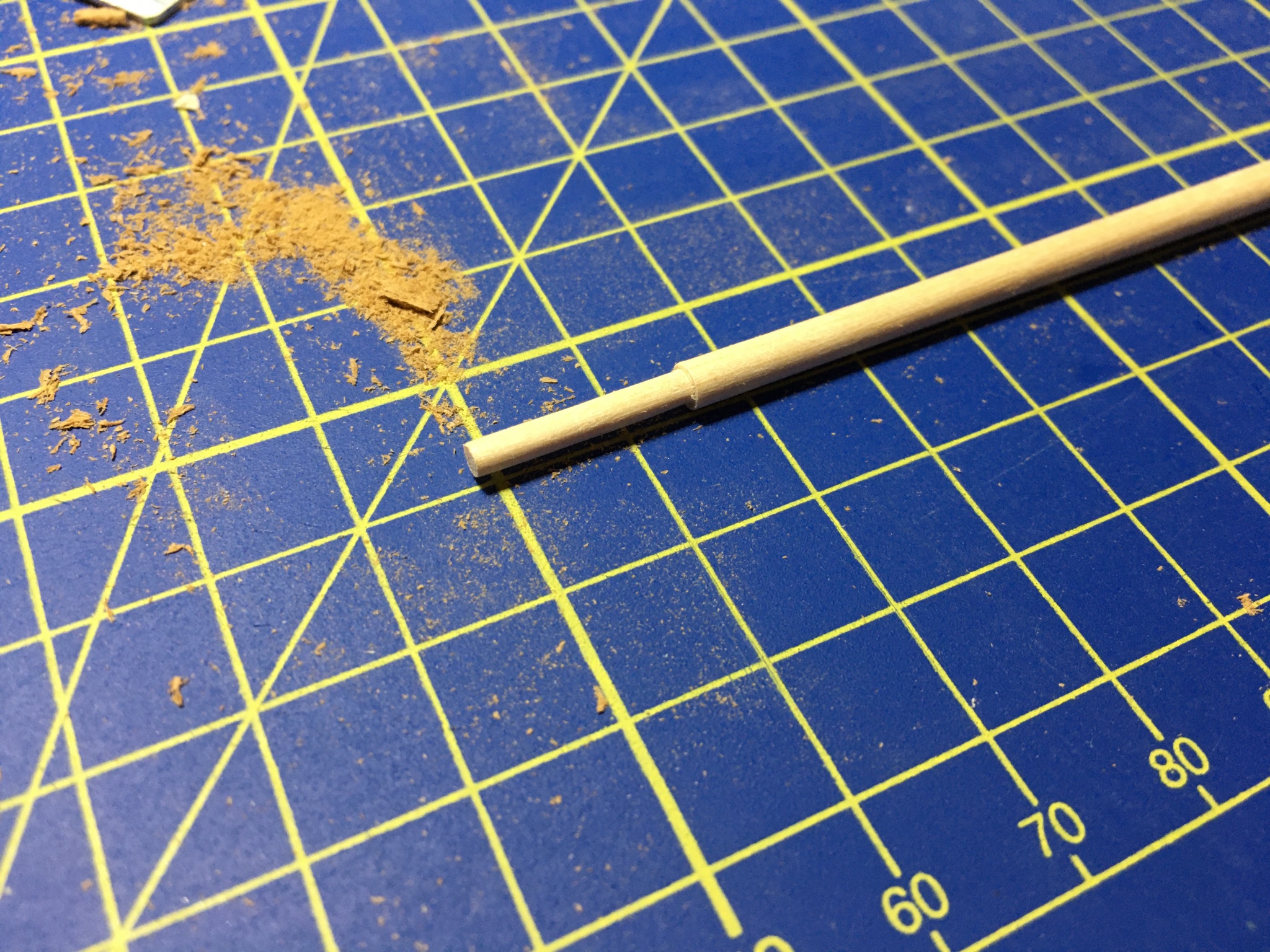
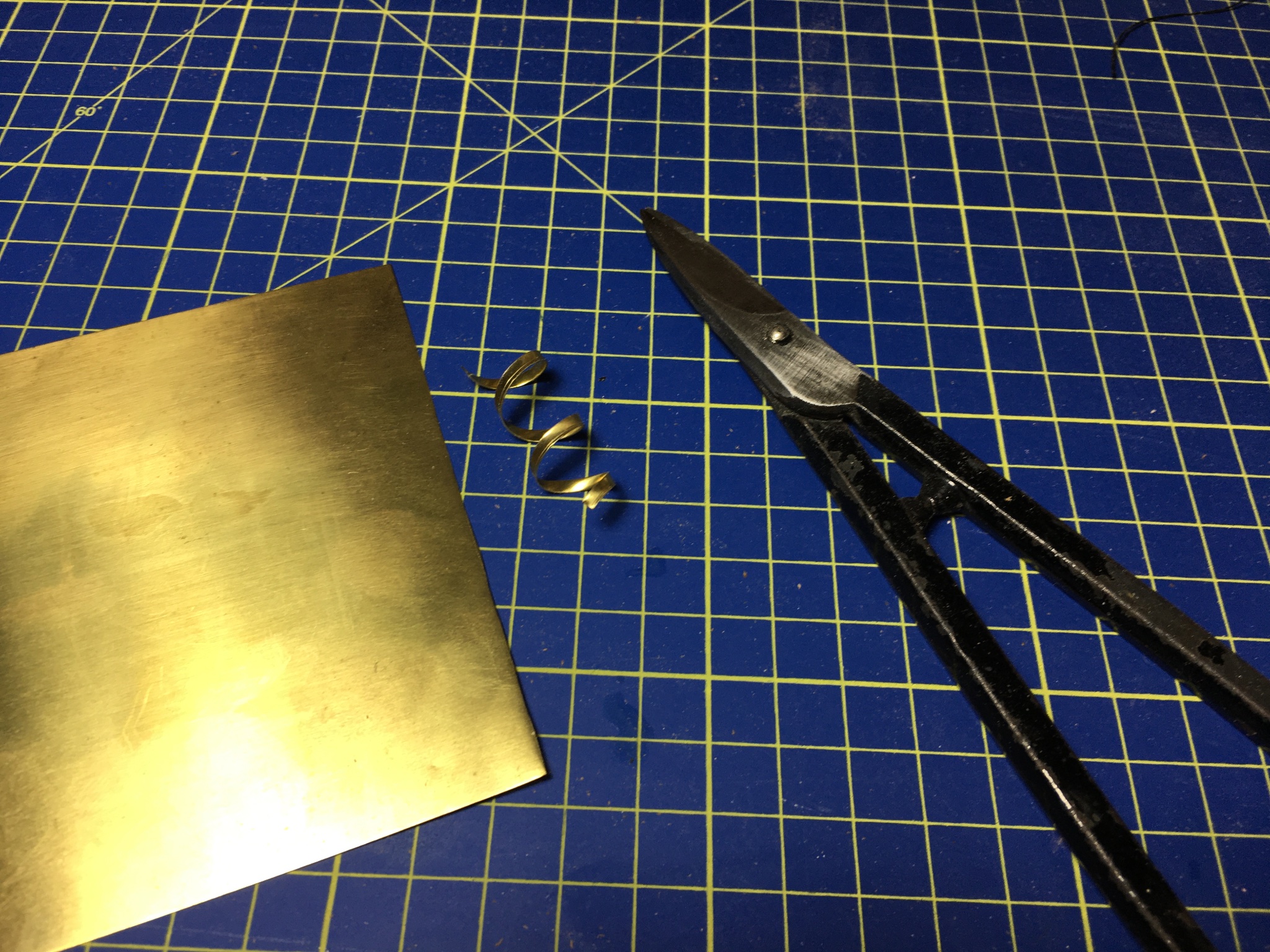
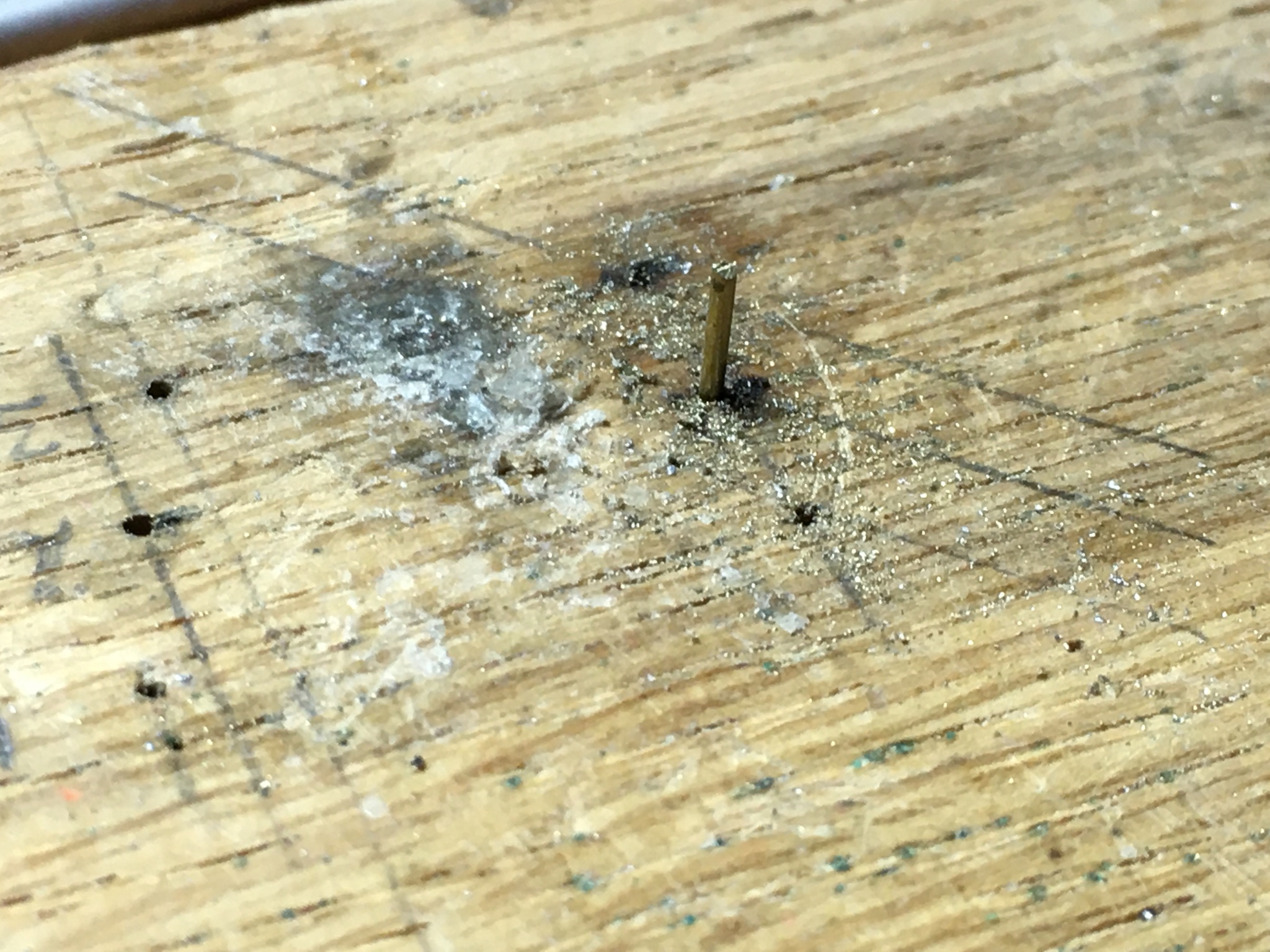
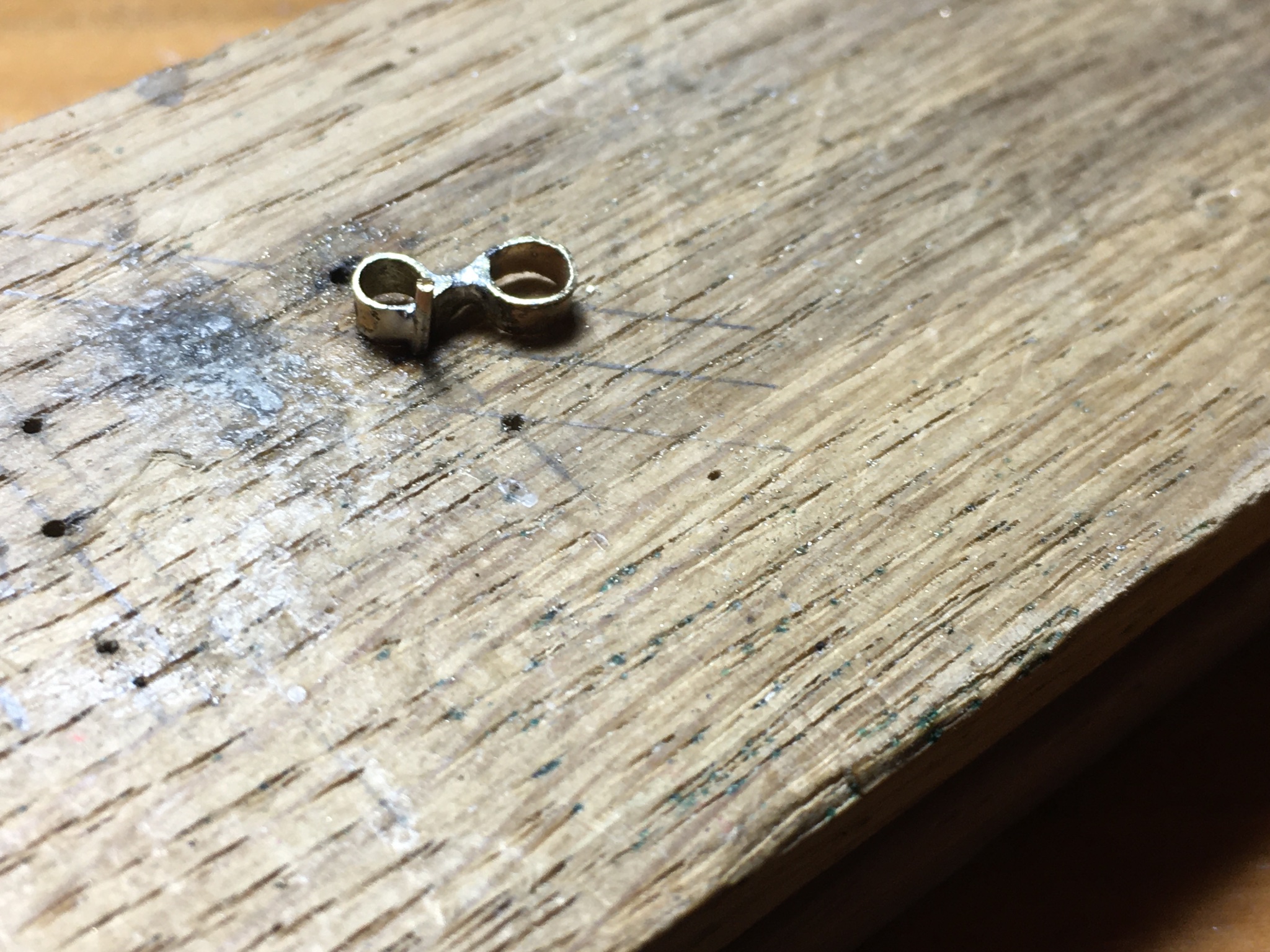
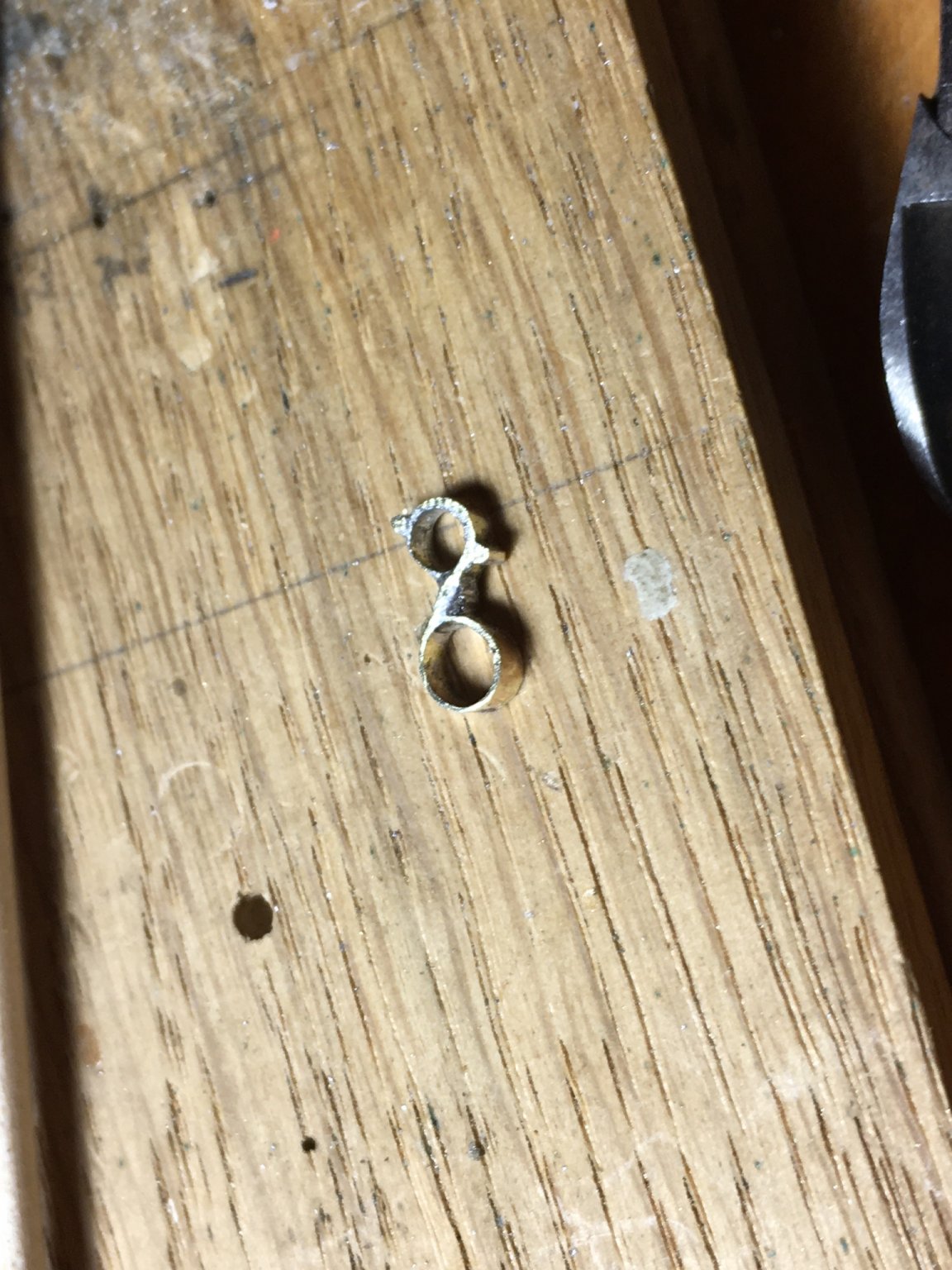
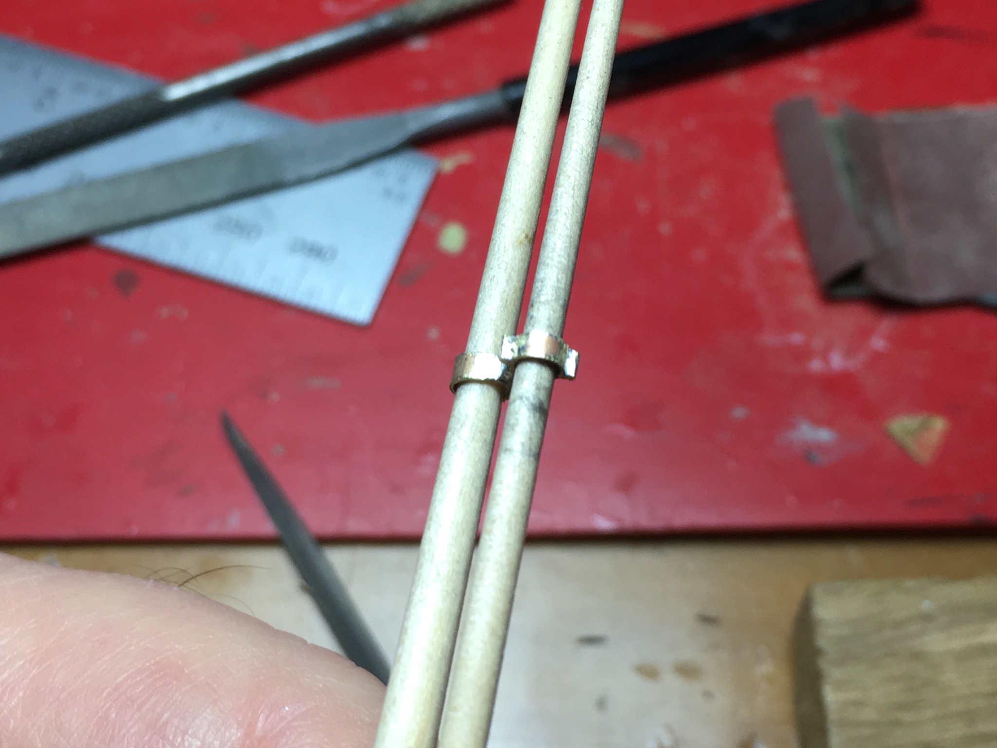
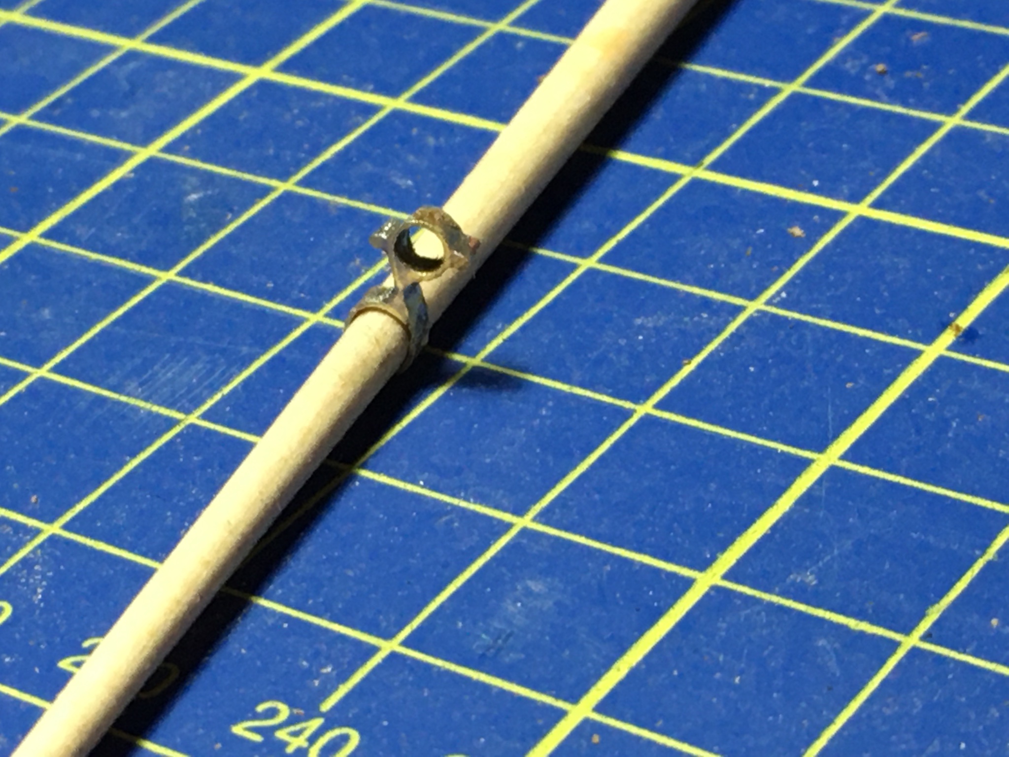
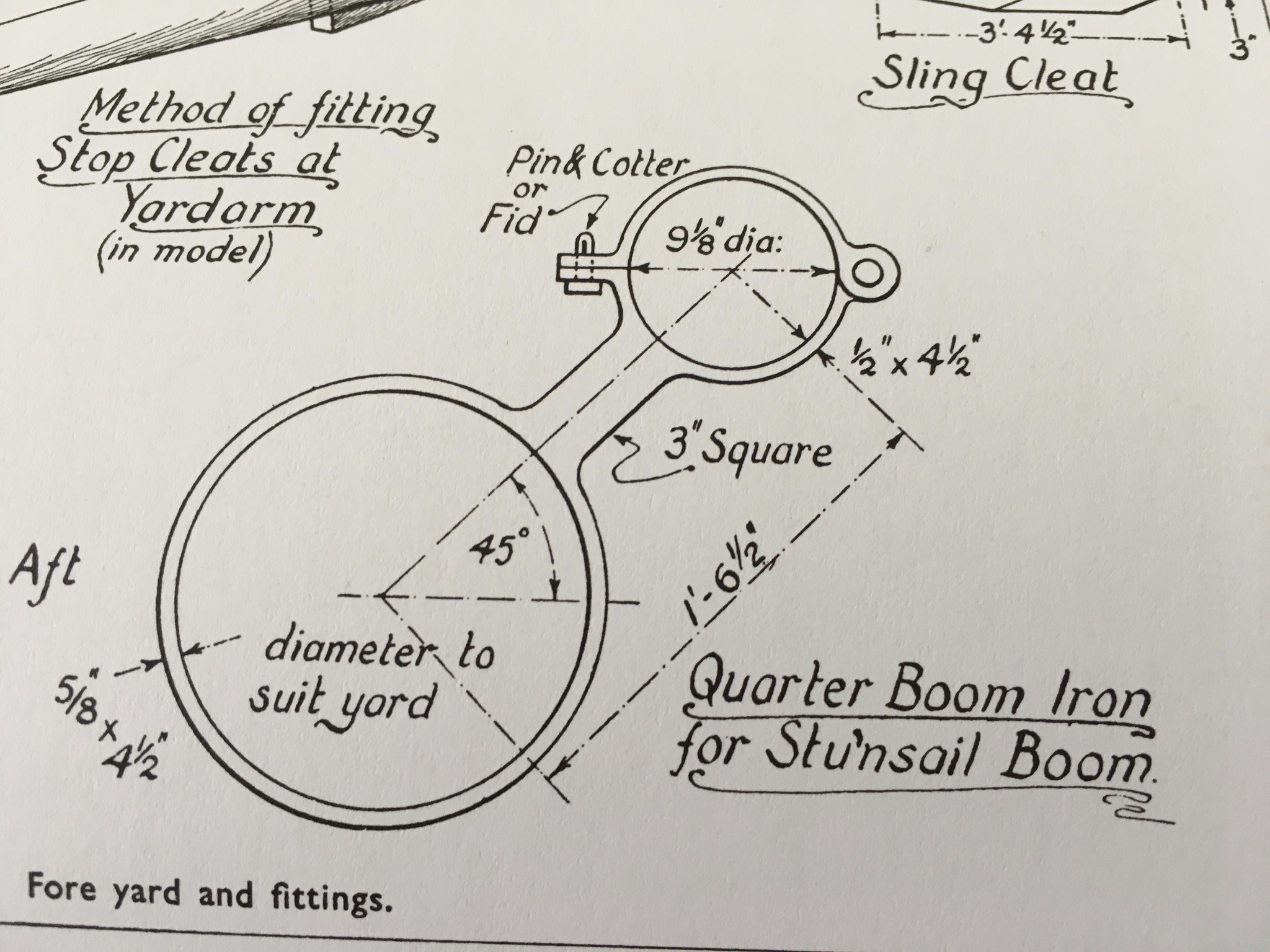
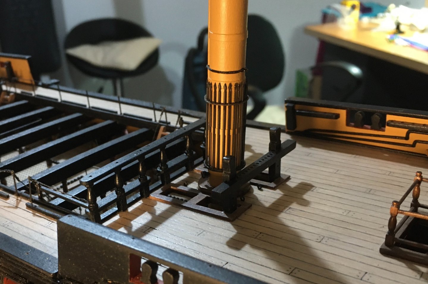
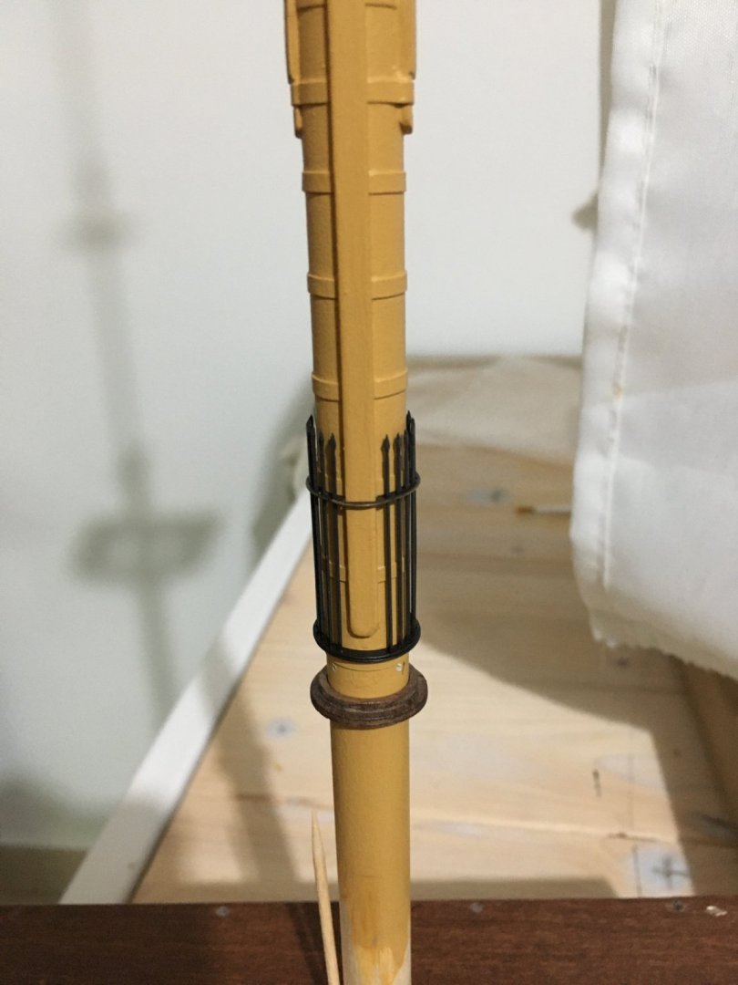
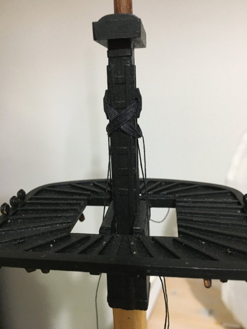
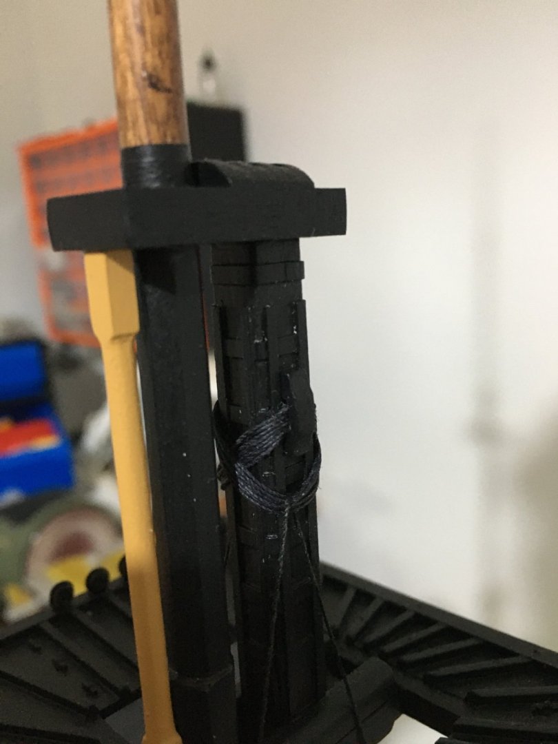
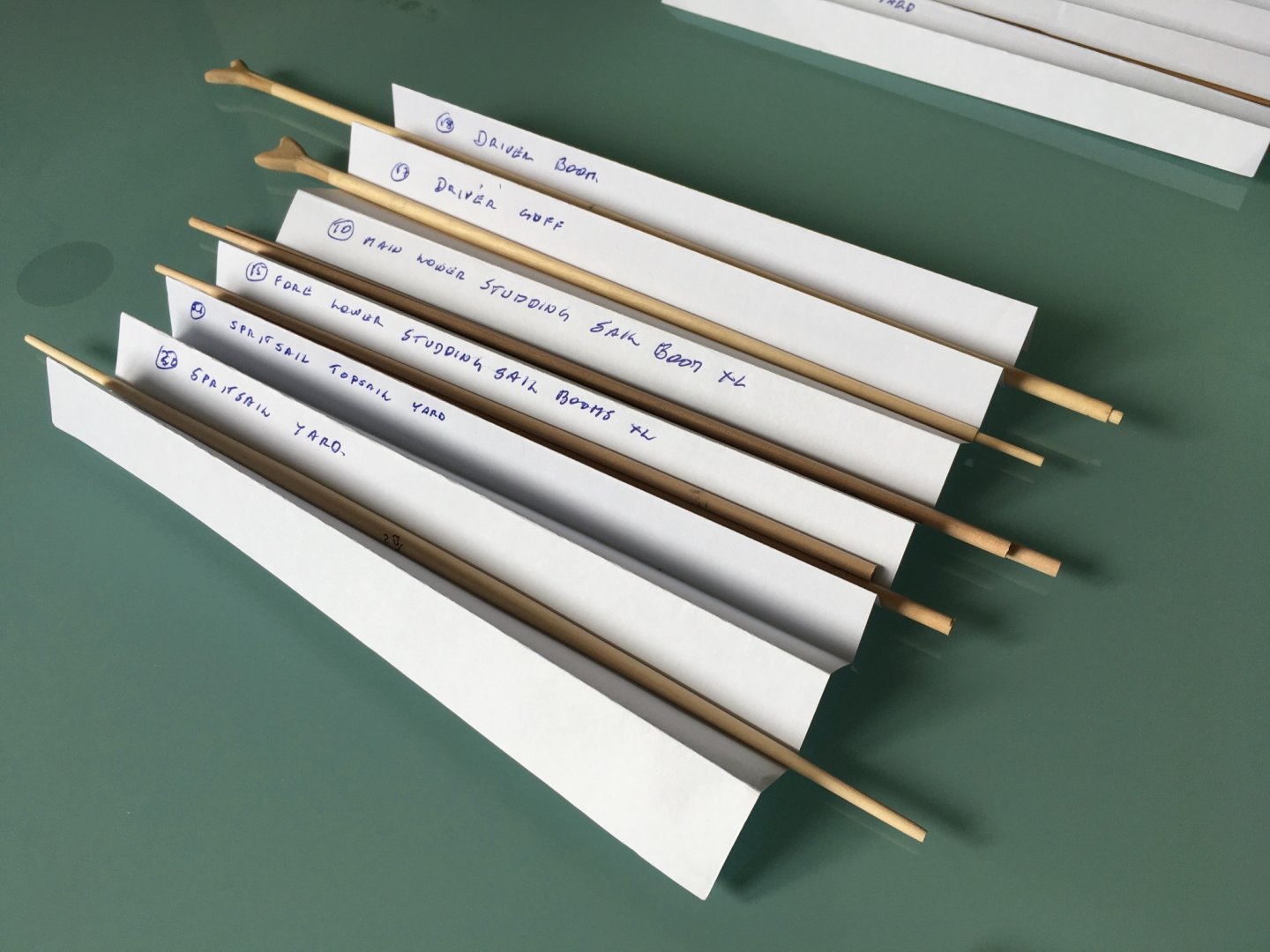
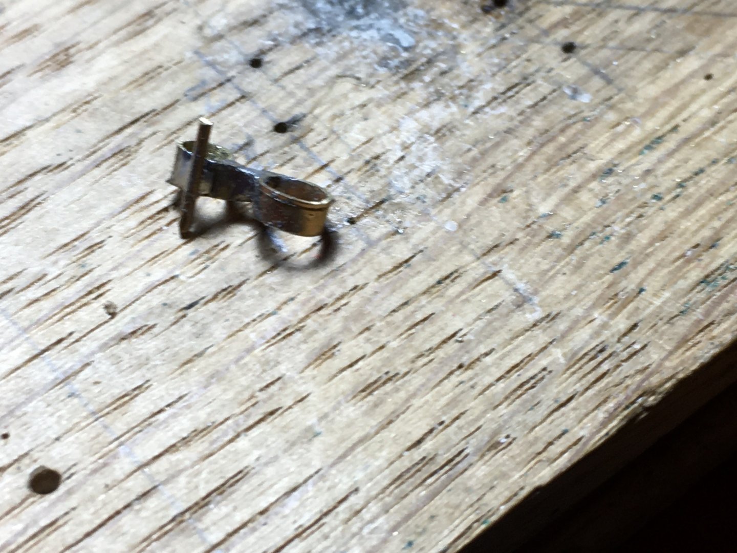
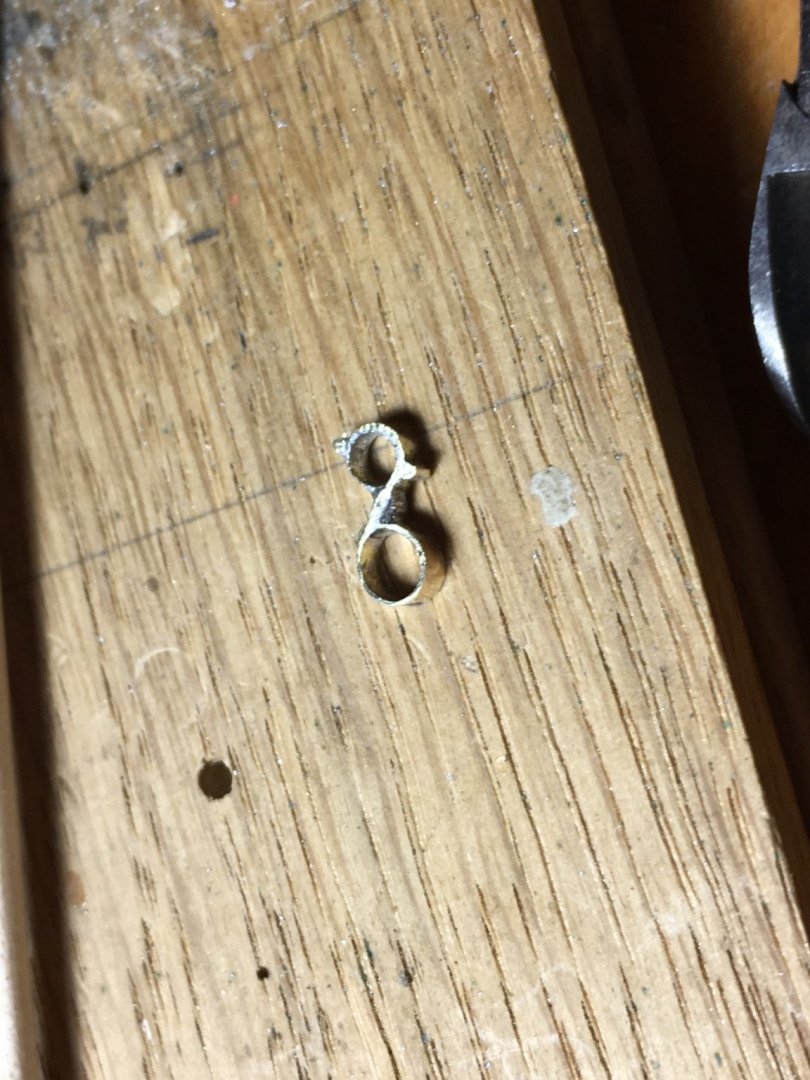
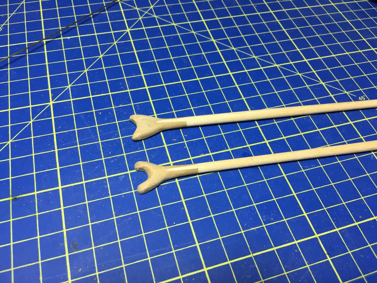
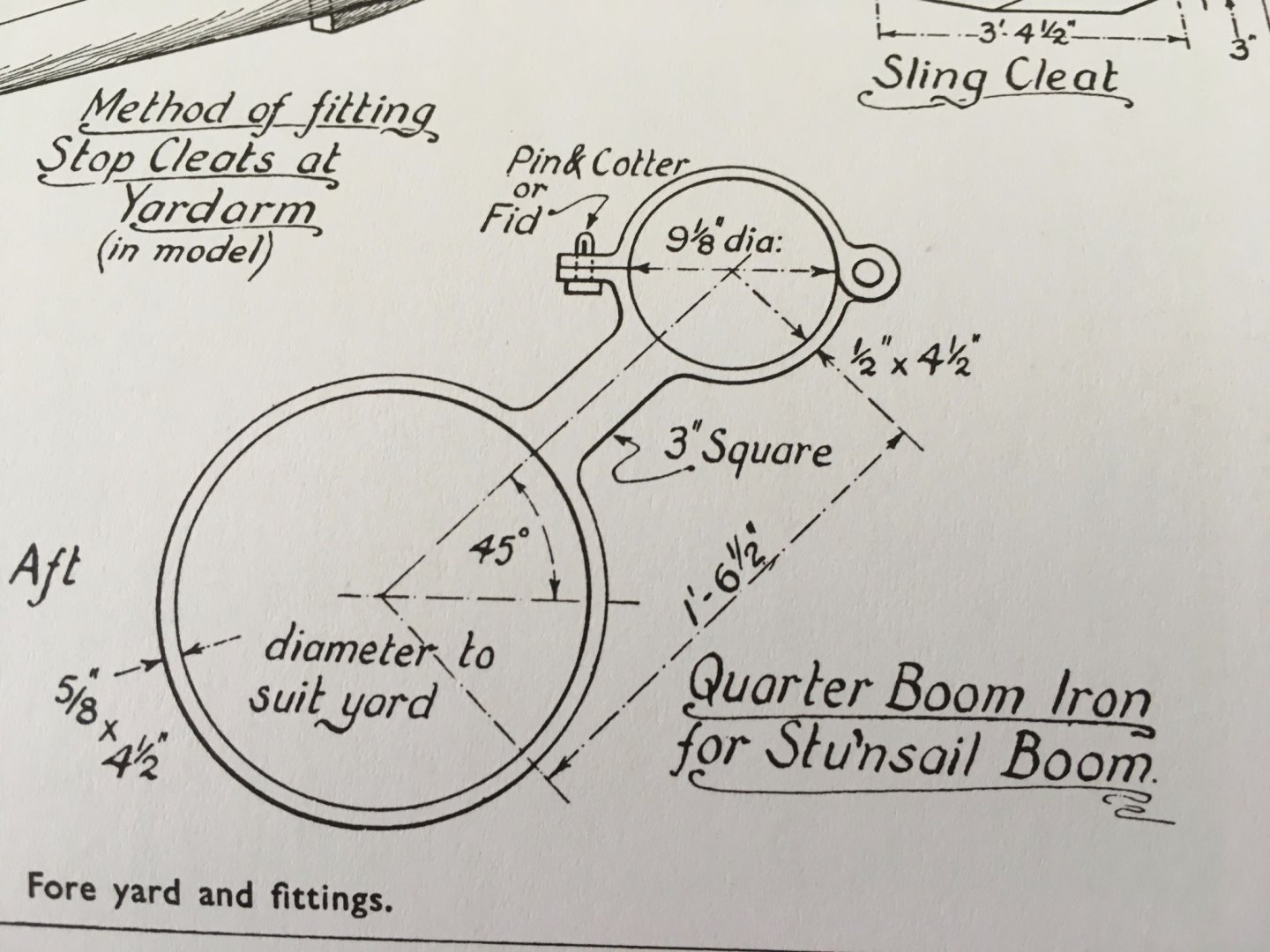
Mort, I took your advice, makes sense to keep the deadeyes all matched. You keep safe too. Thank you all for the likes, here is another update. More work on the masts and yards. Boarding pike racks fitted in place and added the bands that go in between. The mast sleeves are only dry fitted. Prepared the mast head lashings. In the kit manual it is referred to at a much later time, with the shrouds already in place. I thought it would be much easier to lash them now, with the mast in hand. The thread hanging from them is temporarily, just to keep the lashings in place. Shaped and tapered all the yards, except for a couple of them because I ran out of 3mm and 4mm due to damaging them while shaping them. Ordered new ones from CBM. To build the centre octagons on the fore and main yards, first I marked the eight equal parts around the yard, then build around them with the lines as a guide, For the topmasts I did the same thing, but first I glued the four lengths, then fitted the spacers in between. The centre of the mizzen has actually 16 sides, not eight. In the manual it only indicates to fit just the one length of walnut strip at the back, probably for the reason that 16 lengths around the cross jack are going to be very narrow and difficult to do. I had some styrene strips of 0.5mm x 0.75mm and had a go with them. I think they came out quite reasonably good. The topgallant yards centre is also an octagon as in fact indicated on the drawings, but on such a small diameter the sides of the octagon are so narrow that even if you had to manage to do them, probably you would not even notice them, so I am leaving them round. Driver gaff and driver boom. When I came to the yard rings which secure the booms to the yards, apart that I had a few missing, I did not like the white metal once supplied with the kit, some did not fit the yard , too small, some too big, so I decided to try and make them myself from brass. This is a diagram from 'The Anatomy of Nelson's Ships' of the Iron for the stunsail Boom. I found this book really helpful for the build when it comes to some detail. I had a sheet of 0.25mm brass. I cut strips 1.5mm wide and shaped them in a figure of 8, leaving some space in between the rings, making the rings the actual diameter needed for every particular yard and boom. Then soldered them in the middle, at the same time making the part between the rings thicker with the same solder. Then you can trim them with a file, and if any solder has gone on the inside of the ring you can easily remove it wit a round file. To simulate the hinges on the boom rings I cut a small piece of a 0.7mm brass rod, inserted it in a hole on a piece of wood to keep it in place, put the already soldered figure of eight next to it and solder them together. Take it out from the wood, trim it as close as possible wit a side cutter. And finish it wit a file. And this is the result. I have two sets ready, two more to go. after I finish them I will also do the rings at the end of the booms. Robert


- 527 replies
-
- 10
-
-
- caldercraft
- victory
- (and 1 more)
-
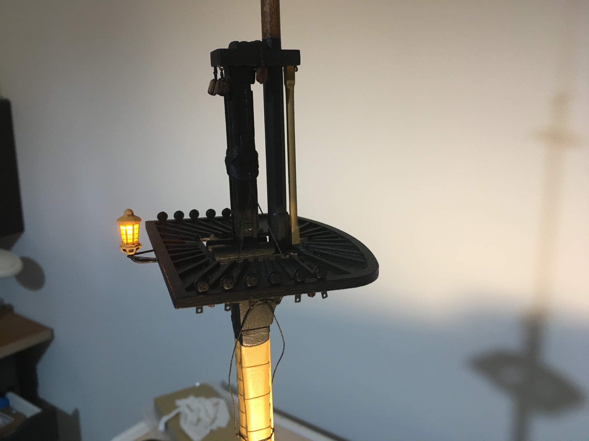
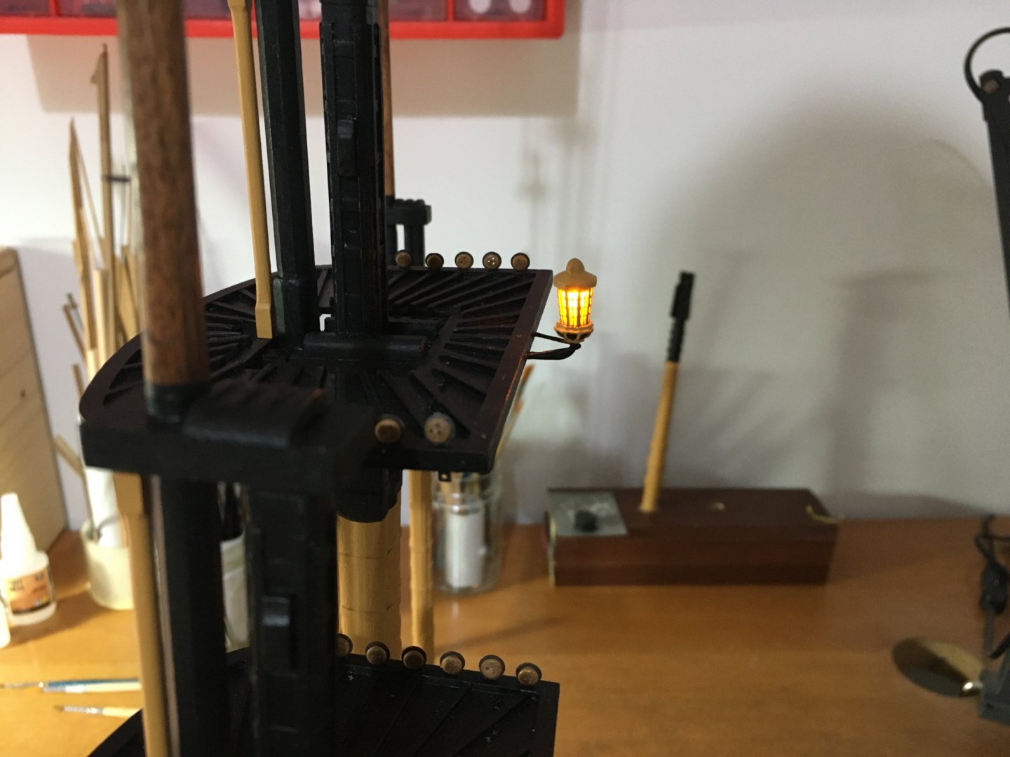
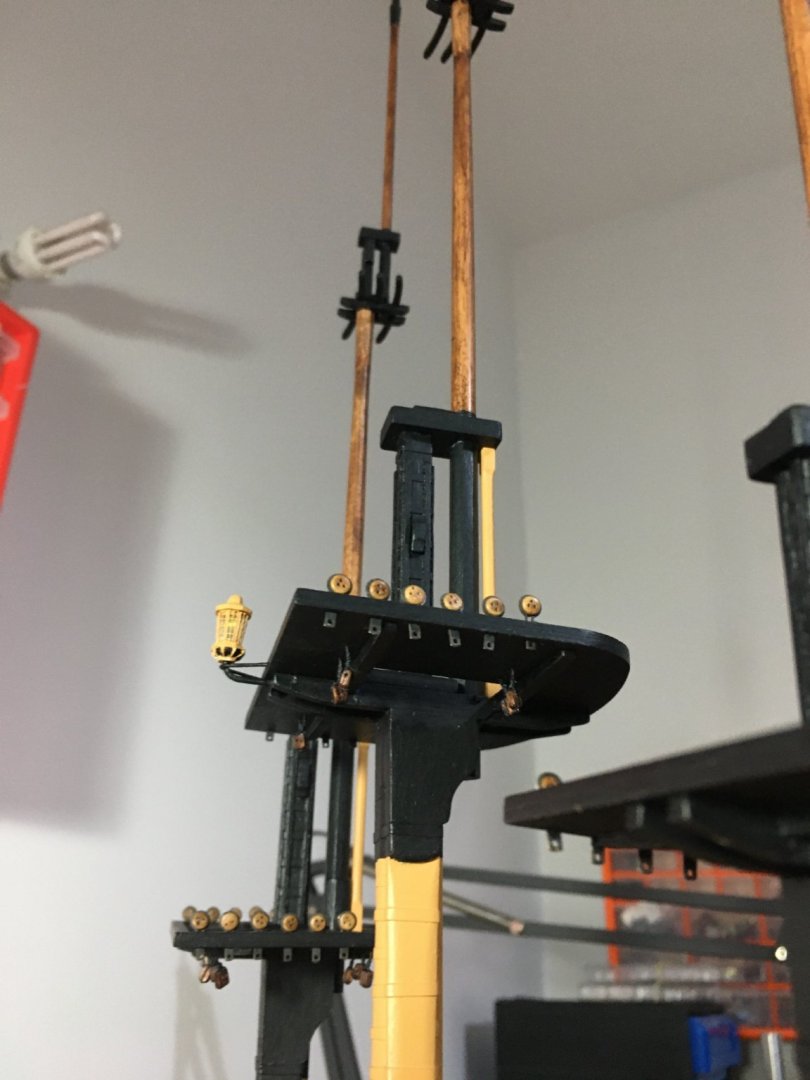
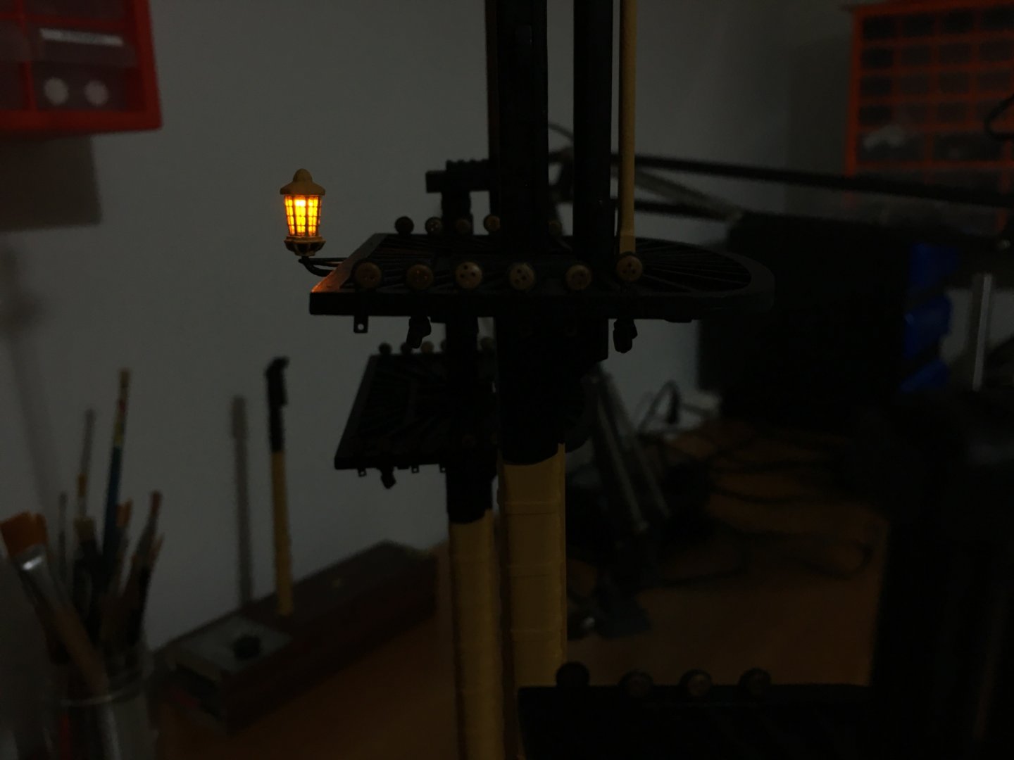
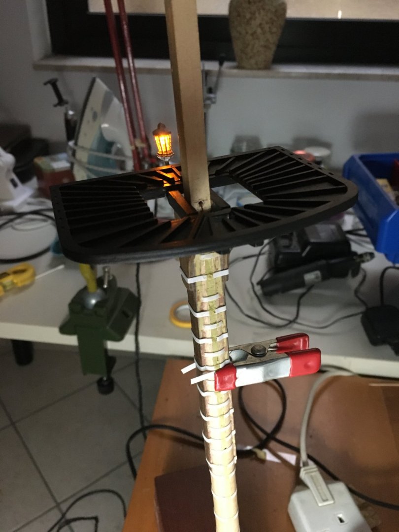
Thank you for your nice comment md1400cs, and thank you all for the likes. A small update on the masts. They are now assembled, lower masts, top masts and top gallants. Dead eyes also in place, their strops have been blackened. I am unsure about the deadeyes, if to paint them black like the once for the lower shrouds, or to leave them as they are. Lantern also assembled in place and connected temporarily to a supply to make sure it functions. Hand masts also painted yellow and glued in place. Tried the lantern in a dimmer light. I am happy with the result. At first I was very hesitant if to put the light in the this lantern or not. The problem I had was not to fit the led in it, but how to pass the wires up to it without any showing and how to connect the same wires with the wires under the deck with the mast already in its place. The resistor for the led is already wired under the deck, so the wires coming out from under the deck are already wired with a resistor in series. Robert


- 527 replies
-
- 10
-
-
- caldercraft
- victory
- (and 1 more)
-
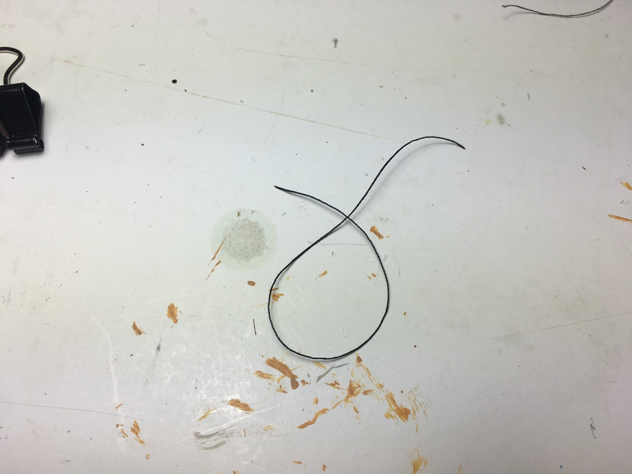
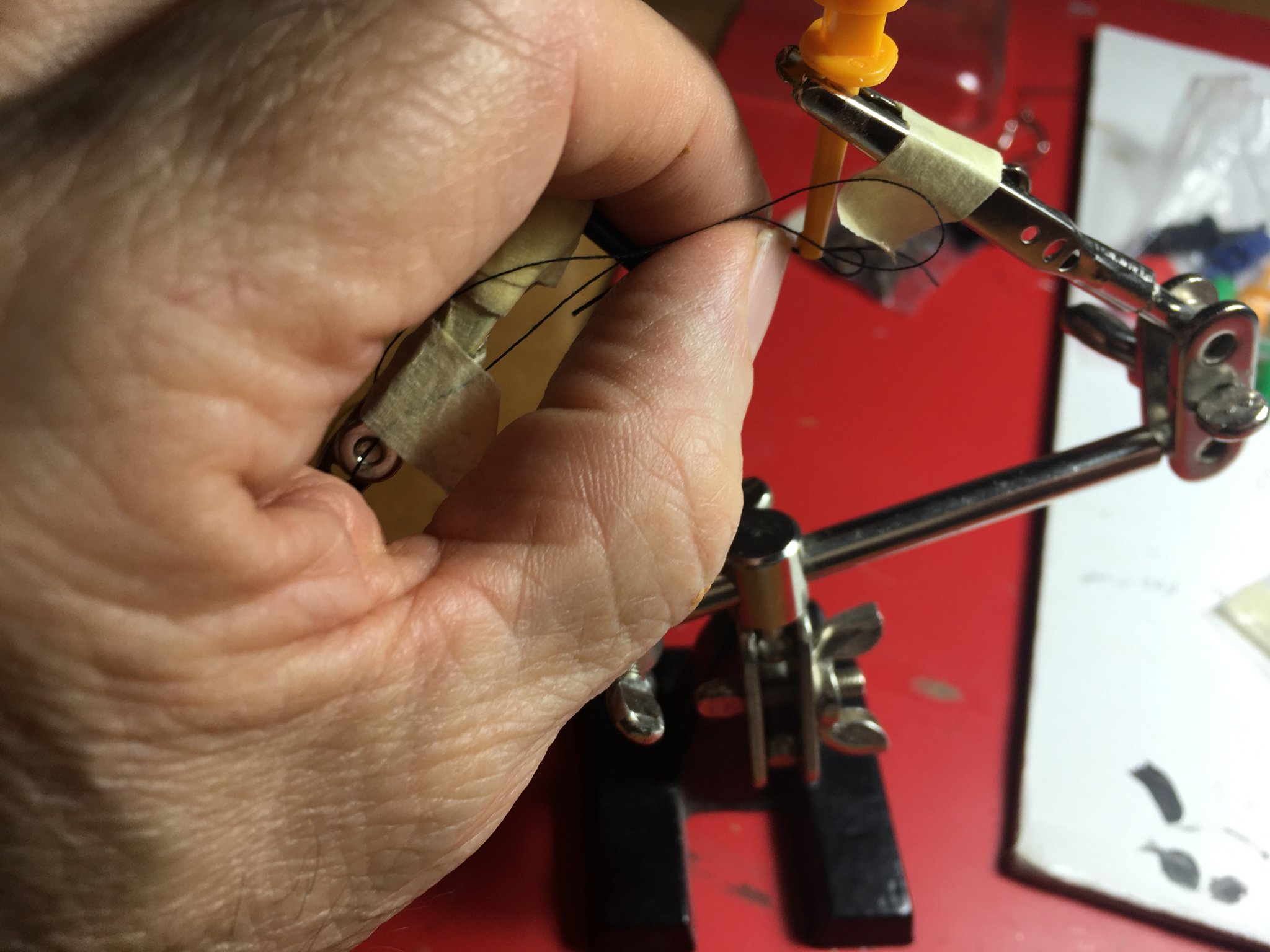
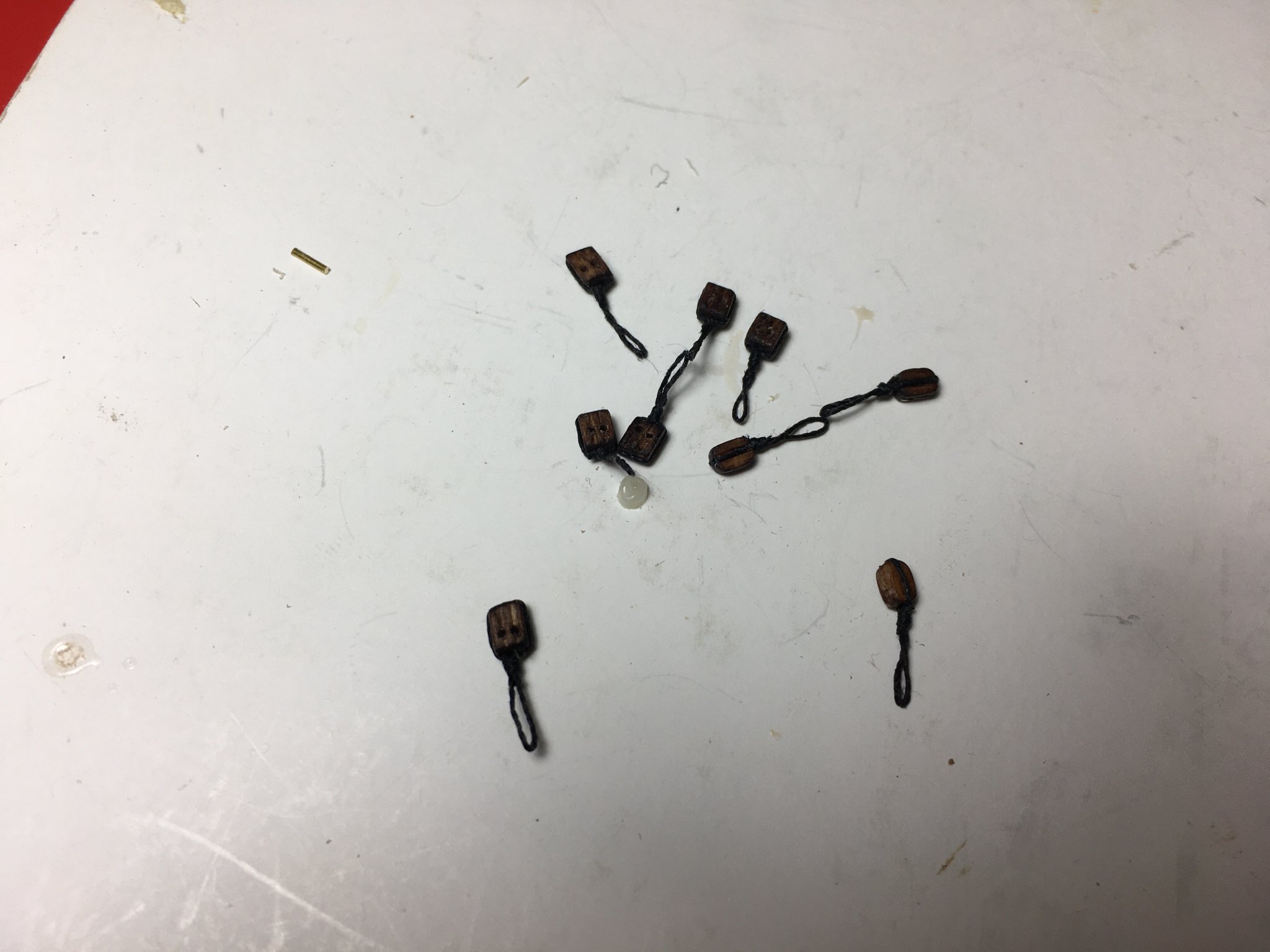
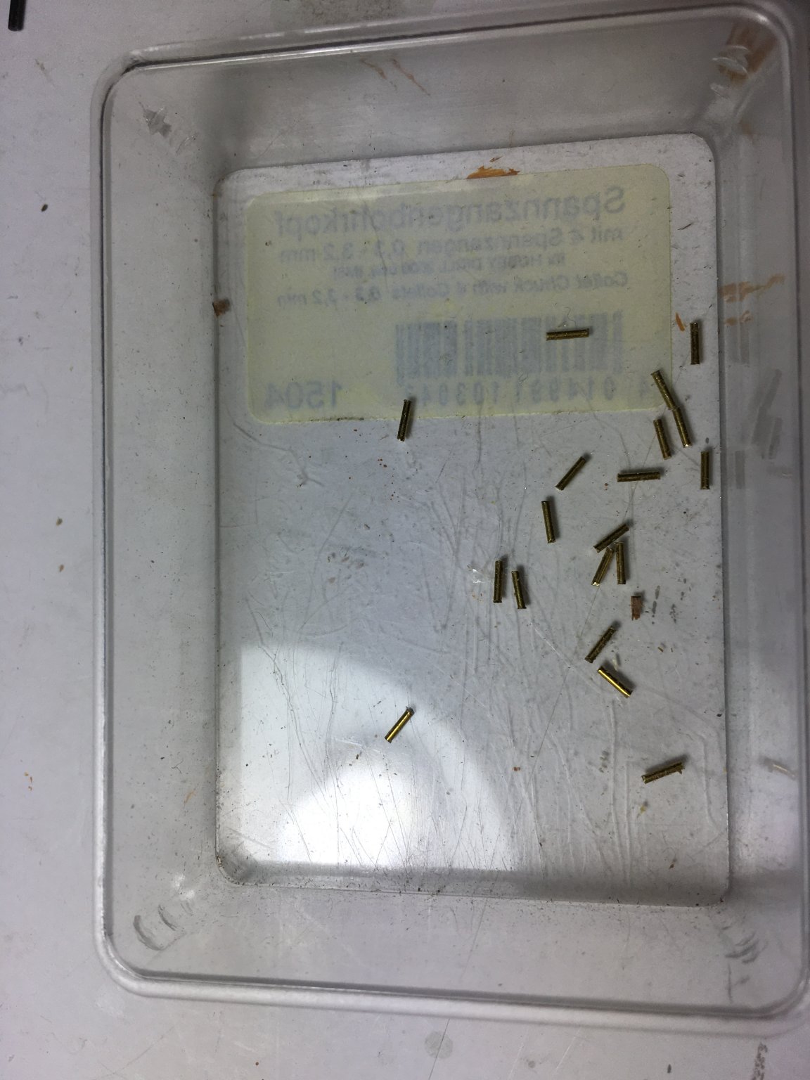
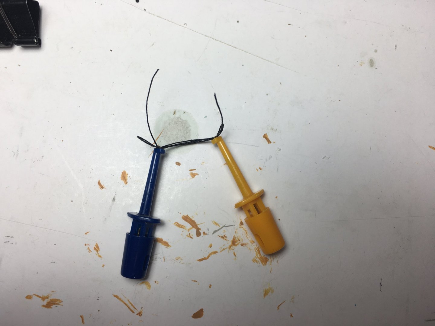
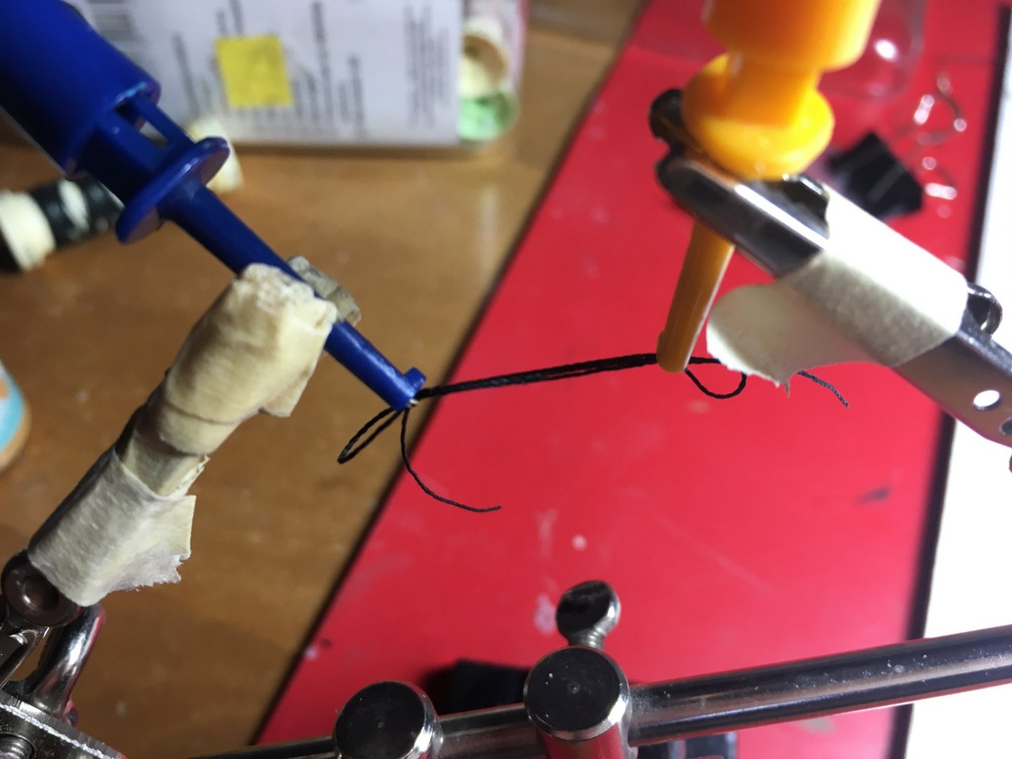
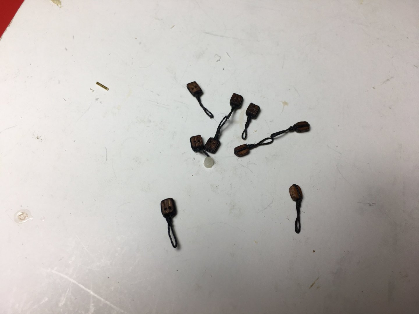
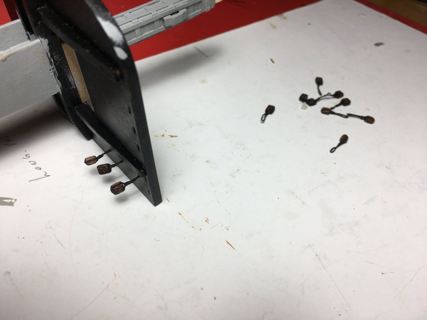
More work on the masts. Finished the bands on the square top end of the lower masts. Also fitted the battens on the corners. To keep them the same distance from the corners I made sort of a quick jig made of two strips glued together as shown on image. Then I made the blocks that are to go under the tops. In the instructions it tells you to fit eyebolts and tie the blocks to them. I used a different way which is more realistic. I made a loop with a thread. Gripped both ends with these electrical clips. And seized them at the middle as per attached you tube video. www.youtube.com:watch?v=C_Au41GG-8g.webloc After seizing you get two loops, one on each side and you can adjust to any size you want by pulling the ends. One loop goes around the block and the other goes through a hole under the top. They are held in place by a piece of brass rod which glued and later painted blacks. Here are a few images of the masts painted and ready to be assembled on top of each other. Robert


- 527 replies
-
- 9
-
-
- caldercraft
- victory
- (and 1 more)
-
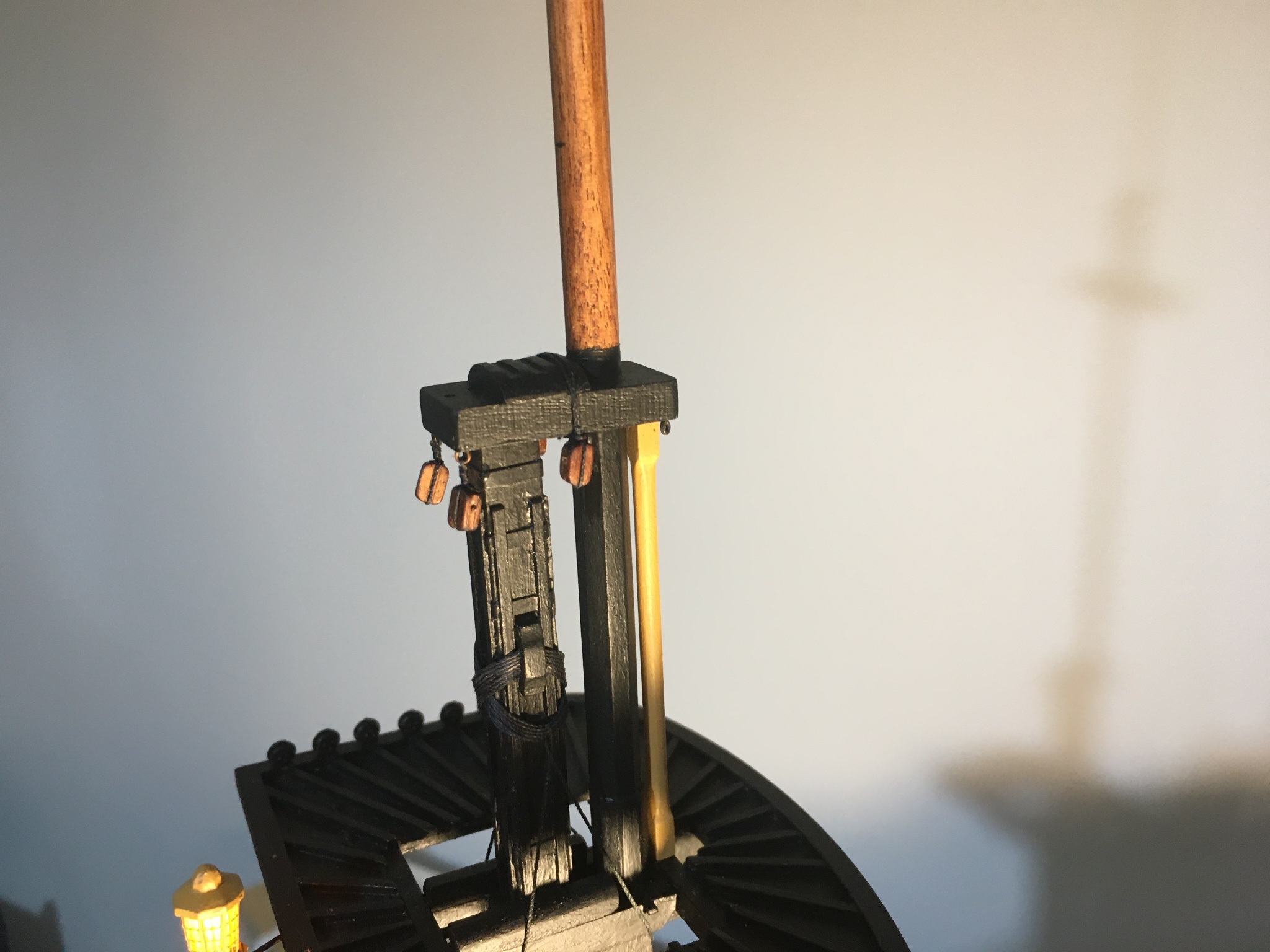
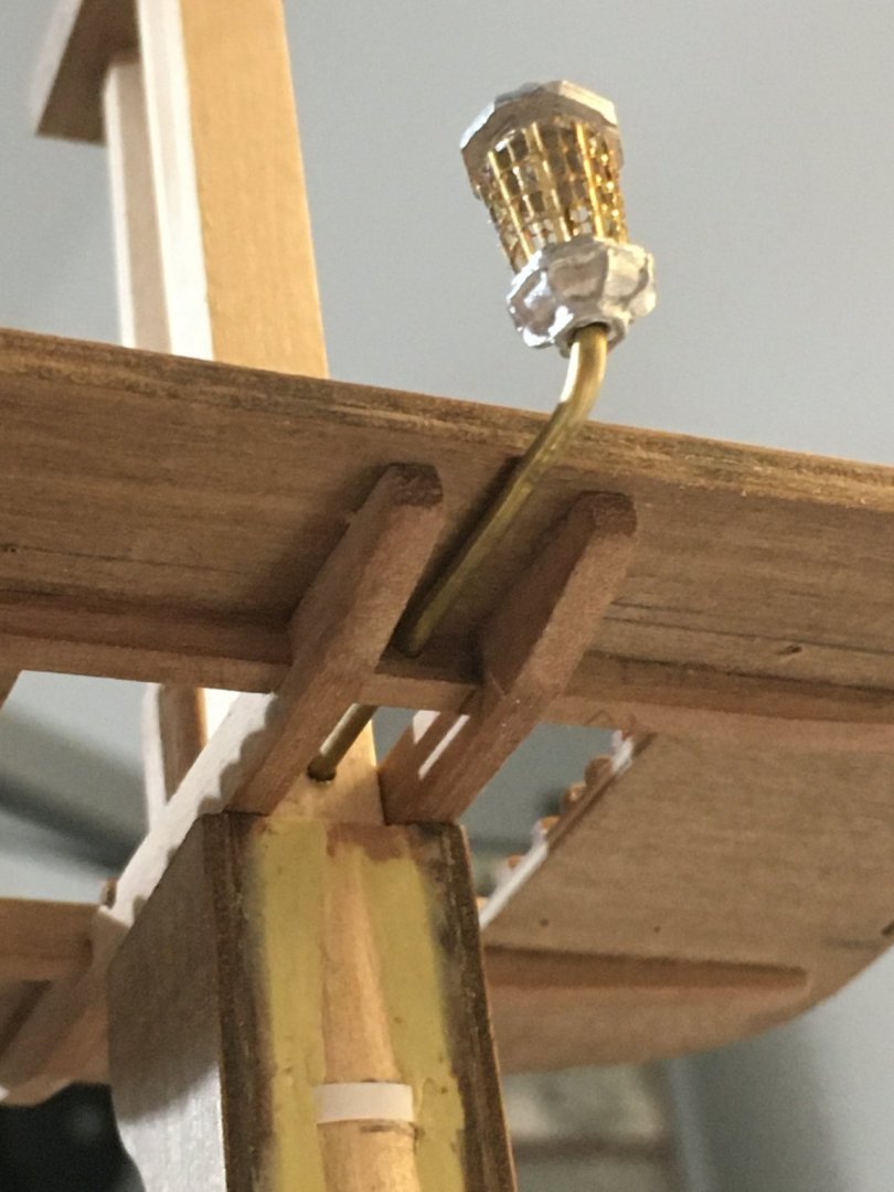
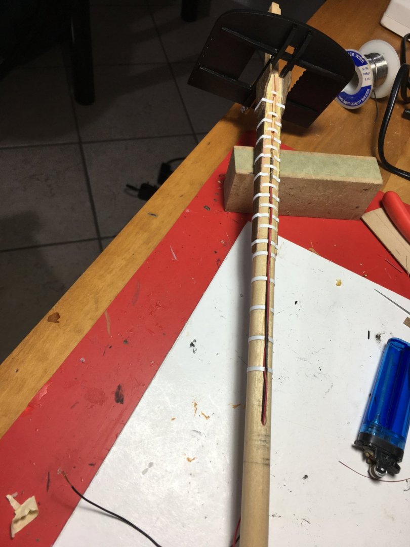
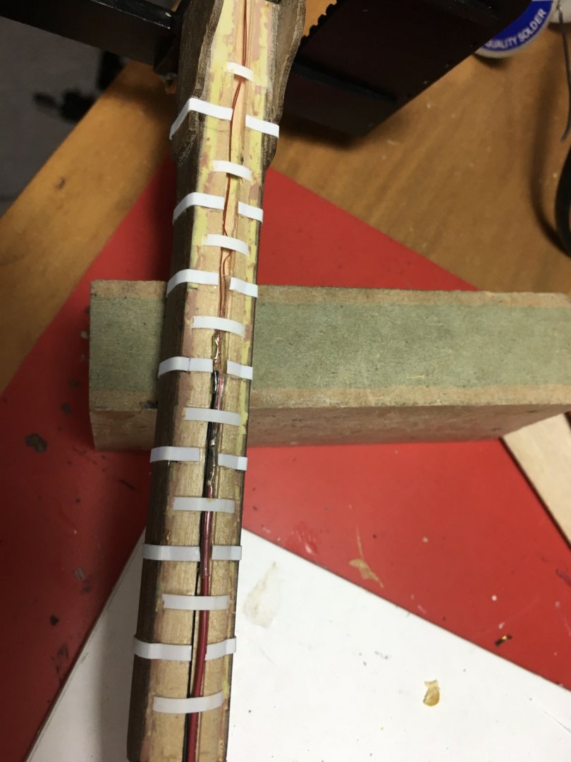
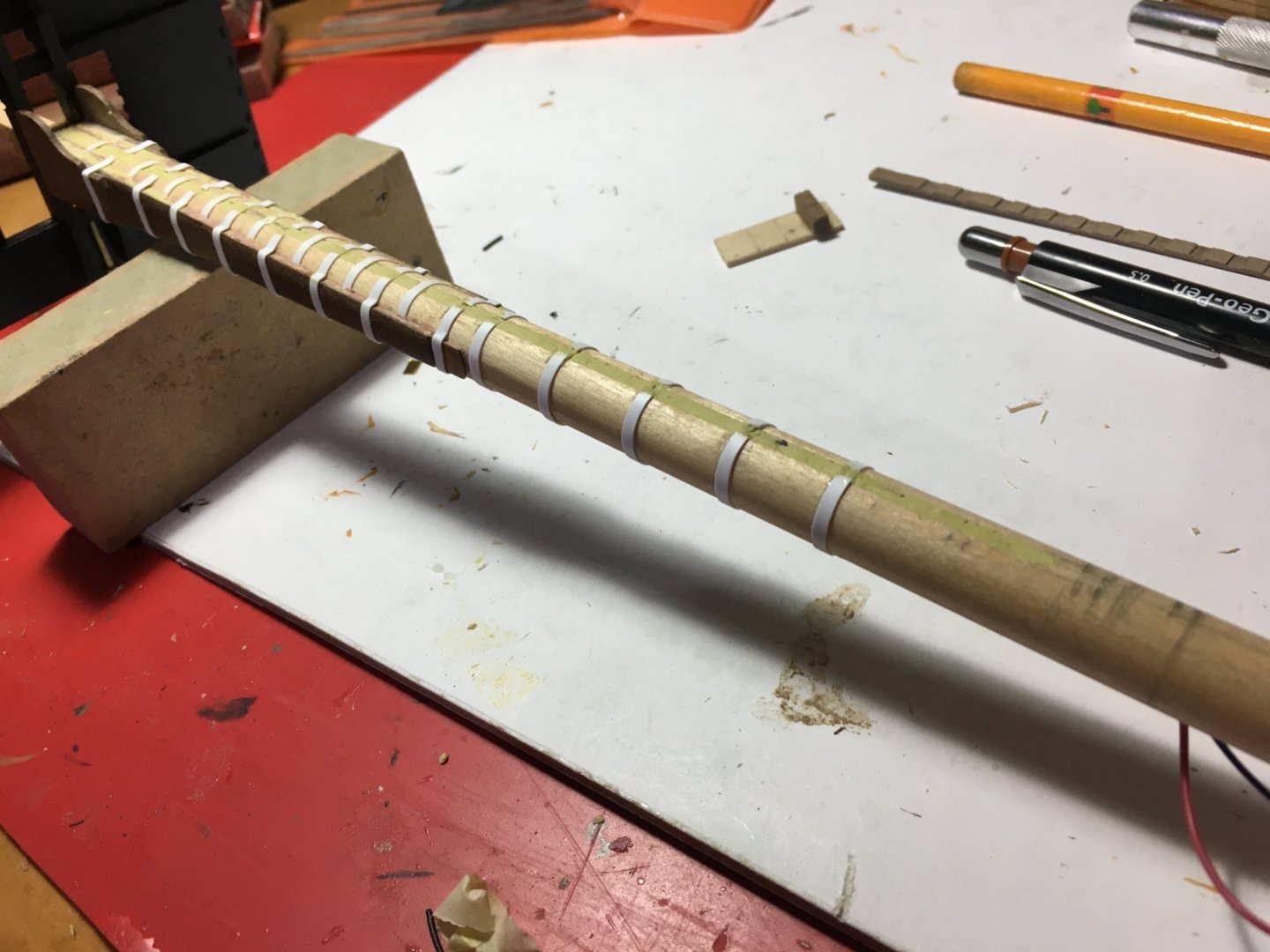
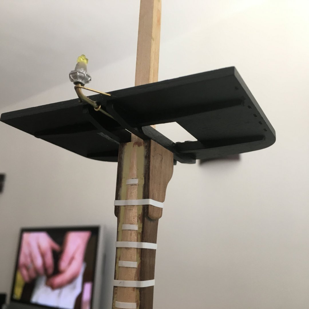
Bossman, thank you for your kind words. I hope some of my ideas will be of some help to other builders as I myself have taken loads of ideas from other builders. Here is an update on more work on the masts. One of my major concerns was how to wire the lantern on the Main Mast without any wiring showing. At this stage all the components of the lantern are only dry fitted. Bending the brass tube with such a short radius without the tube being pinched and the inside hole closing or narrowing down was not easy, but on the third try a managed to bend it and have enough space for the wires to pass. I used very tin wires, the one used for winding transformers. It is only going to have the load of just one led on it. Brass tube goes through the mast just on top of the channel made along the mast. When I saw that everything fitted ok I painted the top and glued it in place. Connected the tin wires to the led and glued, the base of the lantern to the brass tube and the led in place passing the wires from inside the brass tube and turned the tin wires down into the channel. Soldered them to ticker wires so that they will not be so fragile to handle and later on connect to the wires already prepared under the deck. The wires come out on the other side of the mast just under the level of the quarterdeck. Channel filled up with Milliput Clay. I wanted the wires to be solidly embedded so that there will be no room for movement or pulling on the wires that might damage them and also to have a good base for fitting the rubbing paunch on. After I filled the channel I made sure that everything was in place and the light works. To keep the led in place and to make sure the connections do not short with each other or with the body of the lantern I literally embedded the base of the led in epoxy glue. The Araldite epoxy glue is non conductive when dry, so it was perfect for the job. If you look carefully under the top I added a piece of wood on the outer face of the trestletree. After building the top and trying it on the mast I realised that the trestletrees do not lie exactly on top of the bibs. They did not look good and as far as I know I did the masts according to the plans. I noticed on other builds that they had the same problem. Rubbing Paunch glued over the channel, covering all the way from where I passed the wires. The rest of the lantern I will fit later on when the mast is fitted in place as I am sure I will otherwise damage it. Now the remaining problem for this light is to connect the wires to the two supply wires presently coming out from the same hole on the deck where the mast is to be inserted as the connections have to go under the deck. Robert


- 527 replies
-
- 6
-
-
- caldercraft
- victory
- (and 1 more)
-
Jazzyrjw, Good luck on your Victory build. Basically you do not need to paint the bulkheads, you might say I got carried away with the paint. What you have to make sure is that when the hull and decks are fitted none of those areas can be seen, especially through the gunport, as when you have the lights on those brighter areas might show. But as long as you are sure they cannot be seen from any angle, which I am sure mostly are not, there is no need to paint them. Yes, putting in the lights need a lot of planning beforehand, in fact it was a decision I had to make in the very beginning. I was eager to start building the kit, but at the same time I knew that putting in the lights was going to take me longer to start and a lot more work. You have to plan how to supply the led's that come later on in the build and how to hide the wiring and the resistors. I wanted to make sure that no wiring is seen anywhere, not even the once coming out of the ship for the supply. At the moment I am working on the masts and hopefully I will manage to take the supply to the lantern on the main mast without any wiring showing. I avoided connecting any led's in series, they are all connected in parallel, for the simple reason that if one led is burnt all the remaining led's in the same circuit will go off, whilst if connected in parallel it will not effect the others. This means that you have to connect a resistor for each and every led. You also have to decide what you are going to use as a supply. With the amount of led's you are saying there is no way you can supply them from a battery, it will not generate the total current you need. They will either not come on at all or the battery is drained within a minute. You have to use a transformer that can handle the current needed. In my model I have a total of 90 led's, and I calculated that I need 1.8amps. I already had a 12volt transformer that can handle an outputted of up to 4.2amps, so I am using that one. In your case, for 30 led's a 1Amp transformer is more than enough. Two things I always made sure to do were: 1. After fitting any lights always check that they work ok before I continue the build, so that I am in time toI rectify any wrong connections or whatever, because once they are enclosed inside the model there is no way you would be able to reach them again. 2. Make sure that the supply you are connecting them with is the right voltage. Erroneously connecting a higher voltage will burn the led's and you can say goodbye to the lights. I made all my calculations based on a 12v supply. Undoubtedly, I do not have any regrets on the extra work I involved, in my opinion it was worth the result. Robert
- 527 replies
-
- 1
-
-
- caldercraft
- victory
- (and 1 more)
-
Great work Bossman, very neat and detailed. That attention for detail and neat work together with your craftsmanship brings out a an awesome model of the Confederacy. Robert
- 127 replies
-
- 1
-
-
- confederacy
- model shipways
- (and 1 more)
-
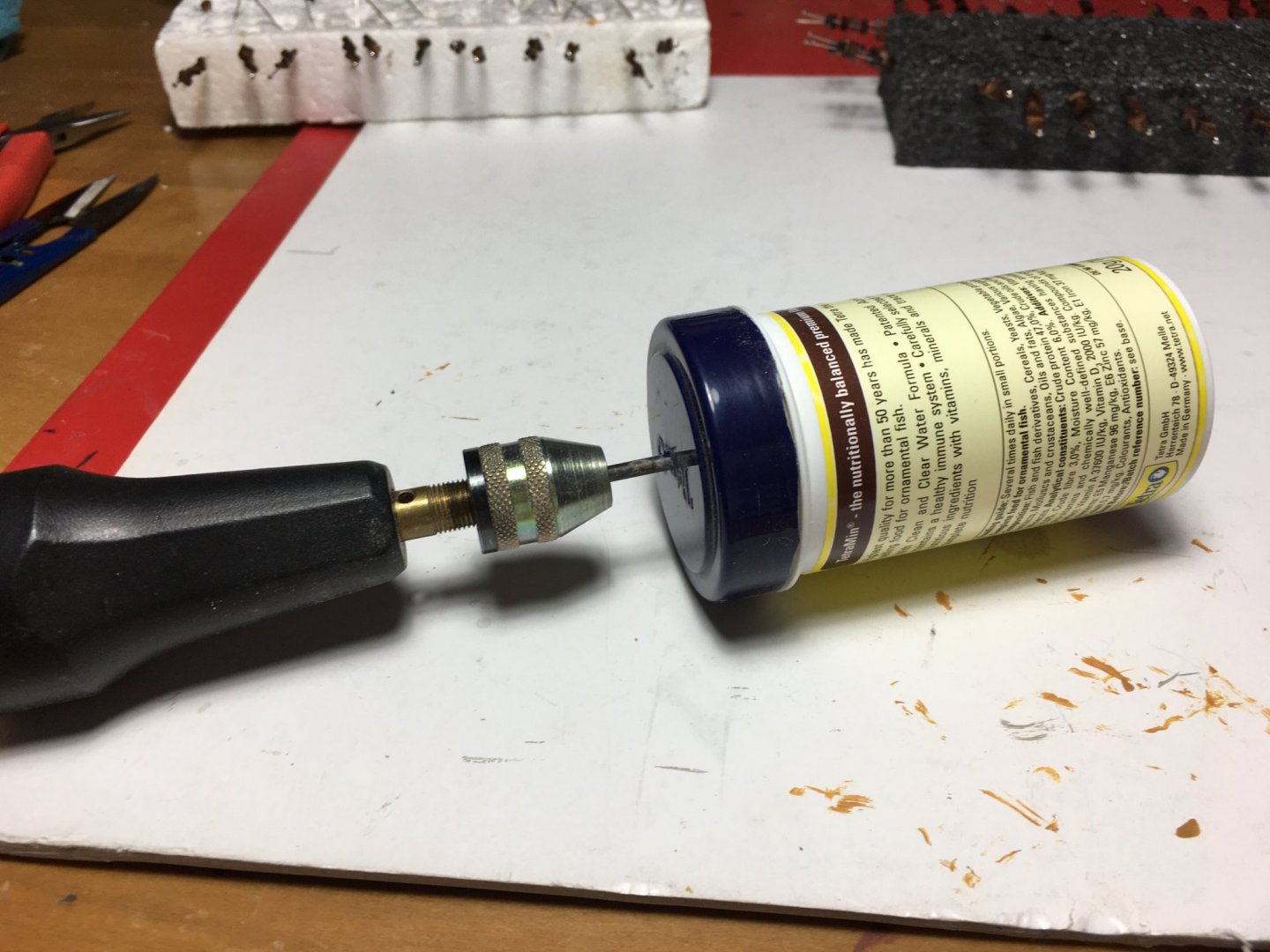
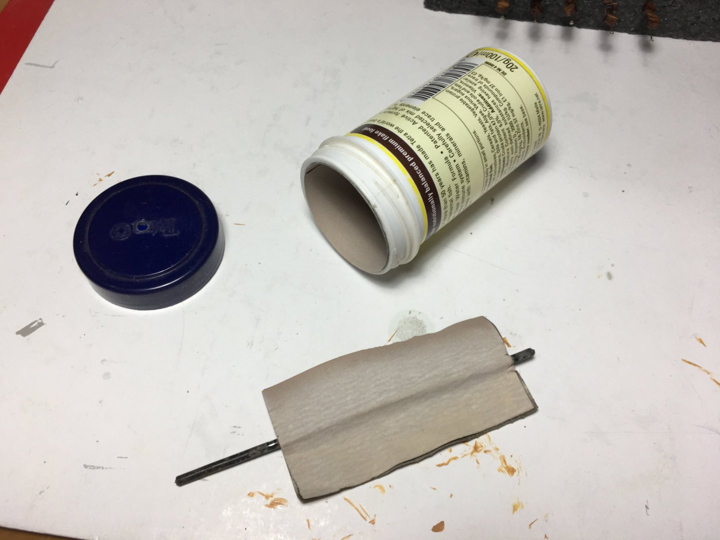
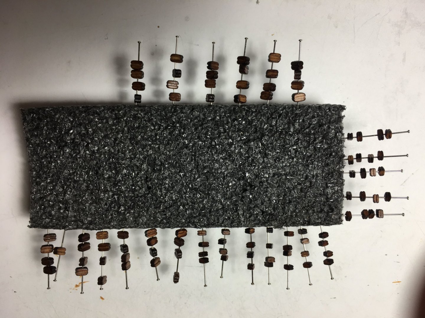
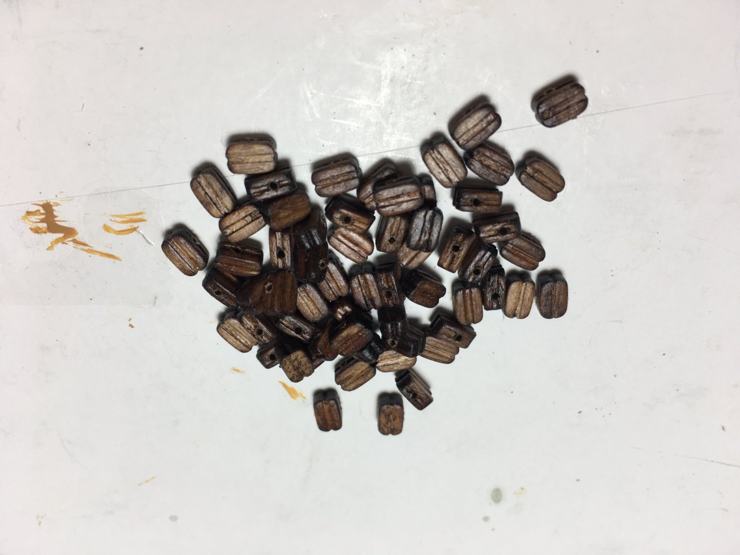
Thank you BenD and thank you all for the likes. A small update: I finished the bands on the three lower masts, except for the very lower once which have to be fitted when the boarding pike racks are being fitted. The groove on the main mast is from where I am to take the wiring up to the lantern. With wiring in place it will be filled and the whole length will also be covered with the 1.5mm x 4mm rubbing paunch. Although some of the bands are cut were they come over the channel, with the rubbing paunch fitted over them they will look like they continue all the way underneath it. The styrene strips are perfect to shape around the masts. When you put ca glue over them they become very flexible and when pressed in place they retain the shape. You have to be careful because sometimes, where you have sharp corners the strip will break in two because of the softening with the ca glue. But once dry they adhere very good to wood. I also prepared all the blocks. Here is a photo of my very crude tumbler which I made to round off the sharp edges of the blocks. It did the job quite well. I decided to darken them a bit. I had some spirit based wood dye, medium oak, and gave them a coat. When dry I gave them a coat of matt satin finish varnish which brings out the dye colour better. I cleaned all the holes to make sure I have no problems when passing the thread through them. Next I am going to work on the tops for the lower masts. I need to fit the blocks to them before I fit the top to the masts. My hesitation is what size of thread do I use to make the strops for the blocks. The kit manual tells you to use 3mm blocks, but doesn't mention what size of thread to use. Any suggestions? Should it be the same size of the rope being rigged on it!!!! Robert


- 527 replies
-
- 6
-
-
- caldercraft
- victory
- (and 1 more)
-
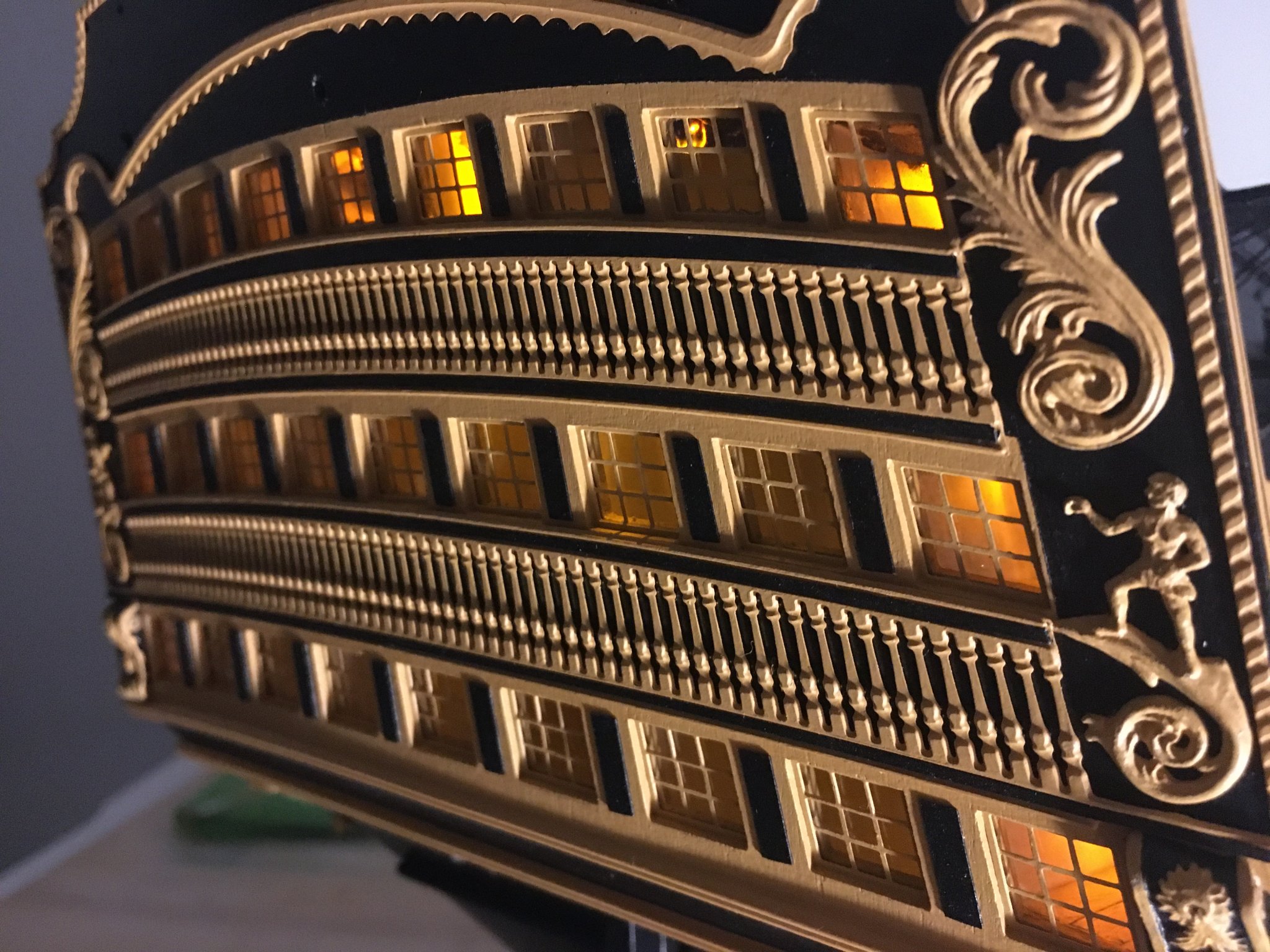
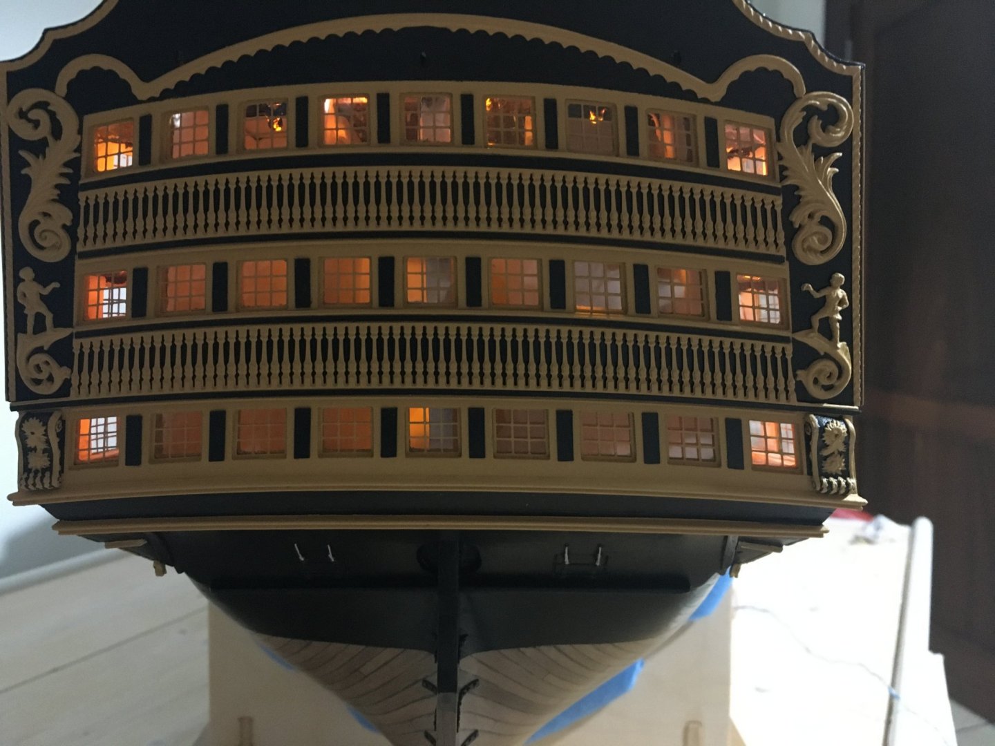
Thank you Stuglio. Here are a few more photos with the stern lights on. Robert

- 527 replies
-
- 14
-
-
- caldercraft
- victory
- (and 1 more)
-
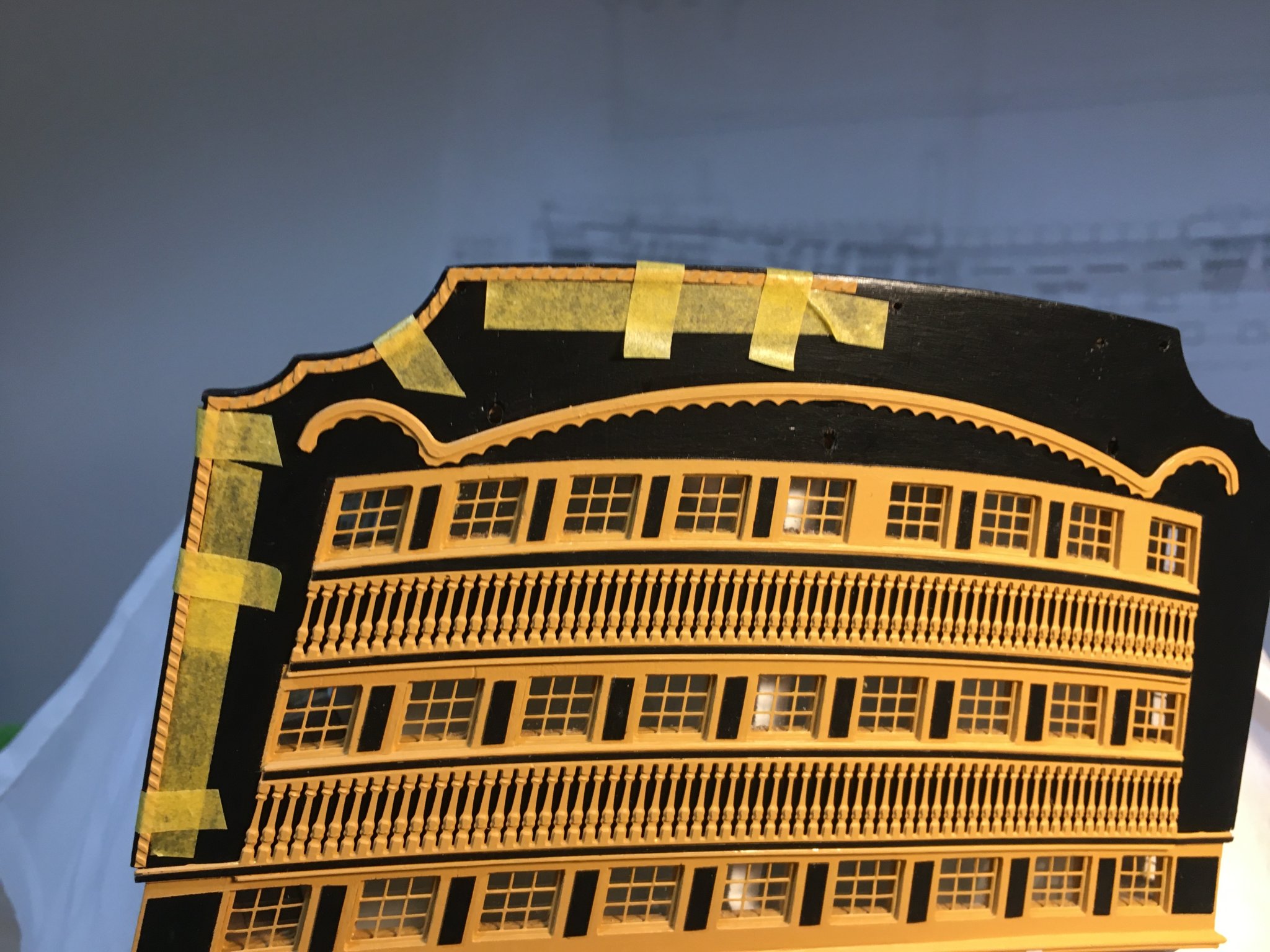
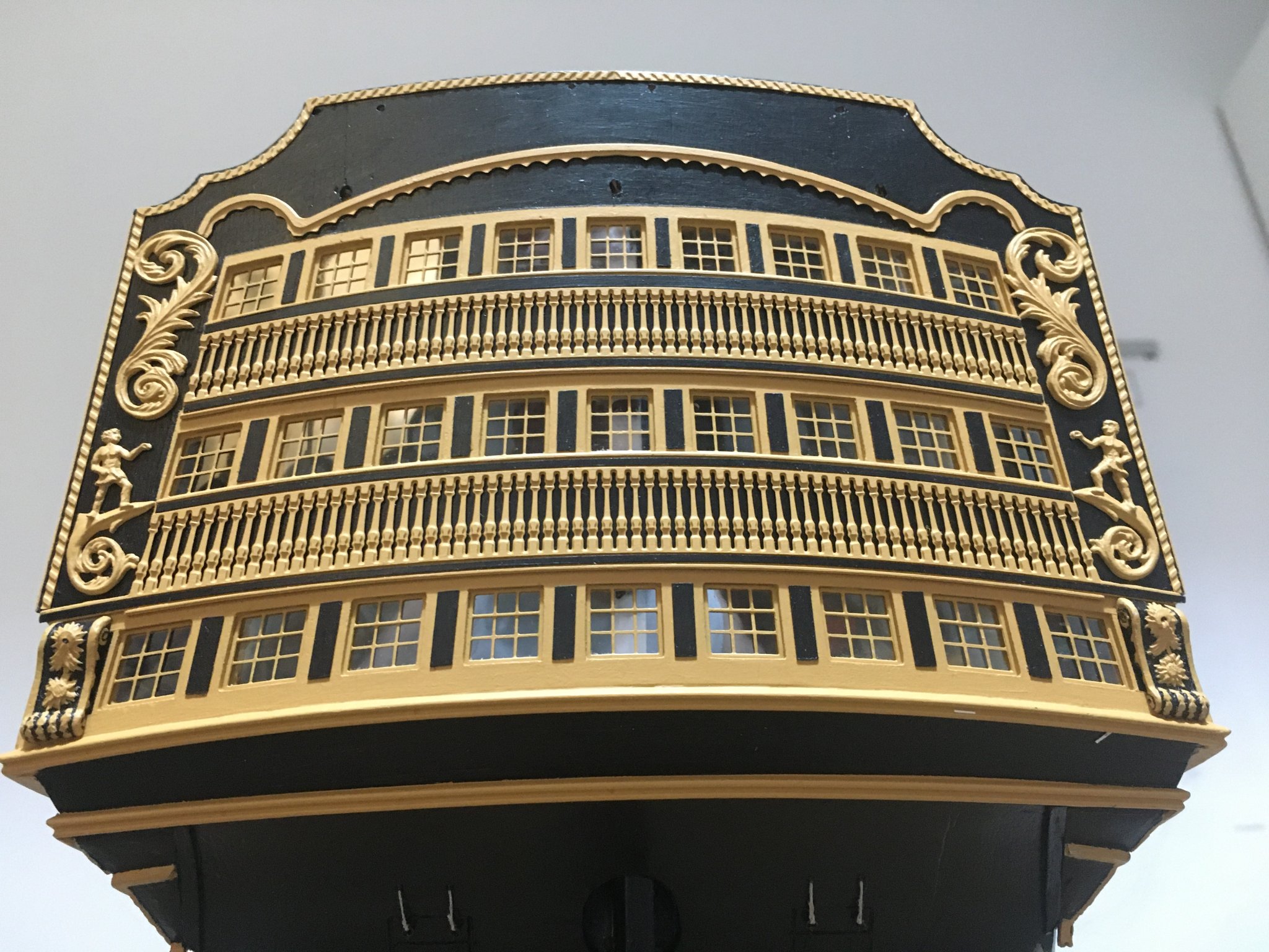
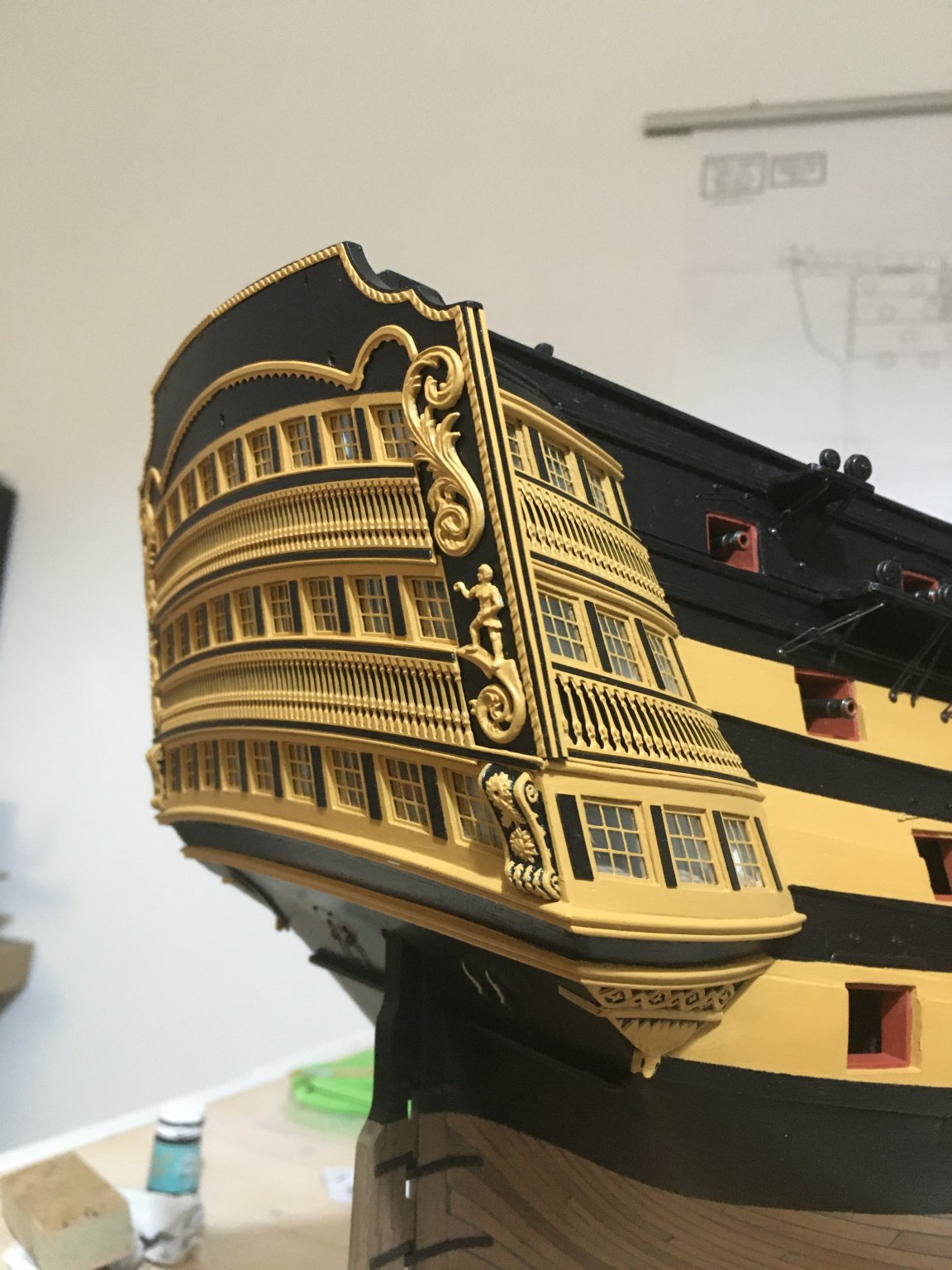
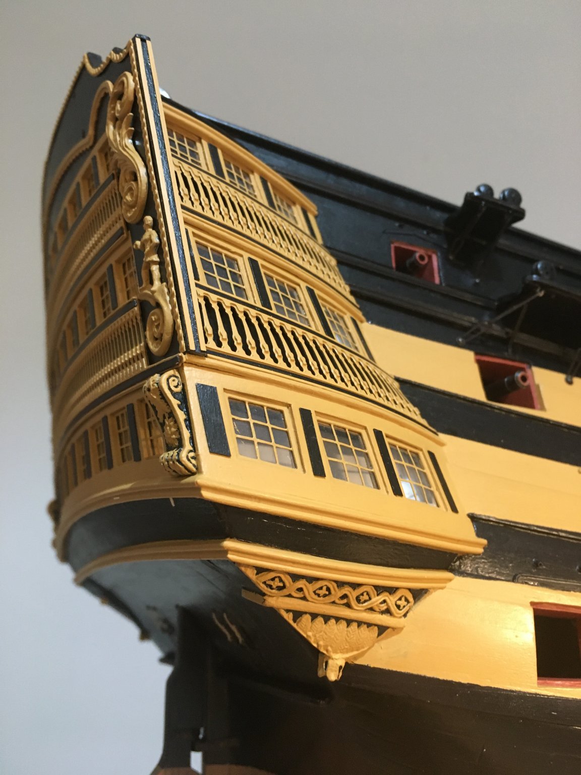
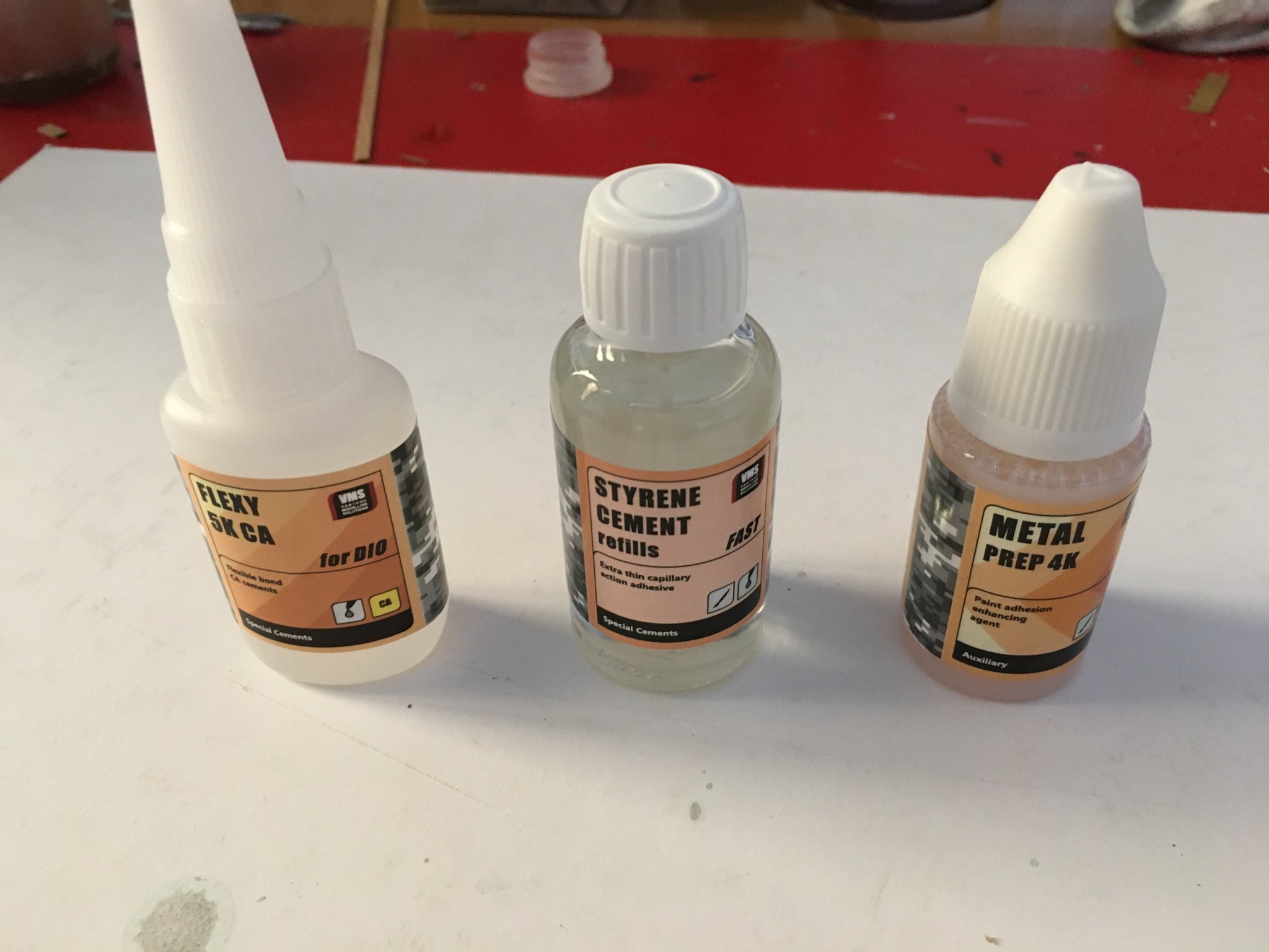
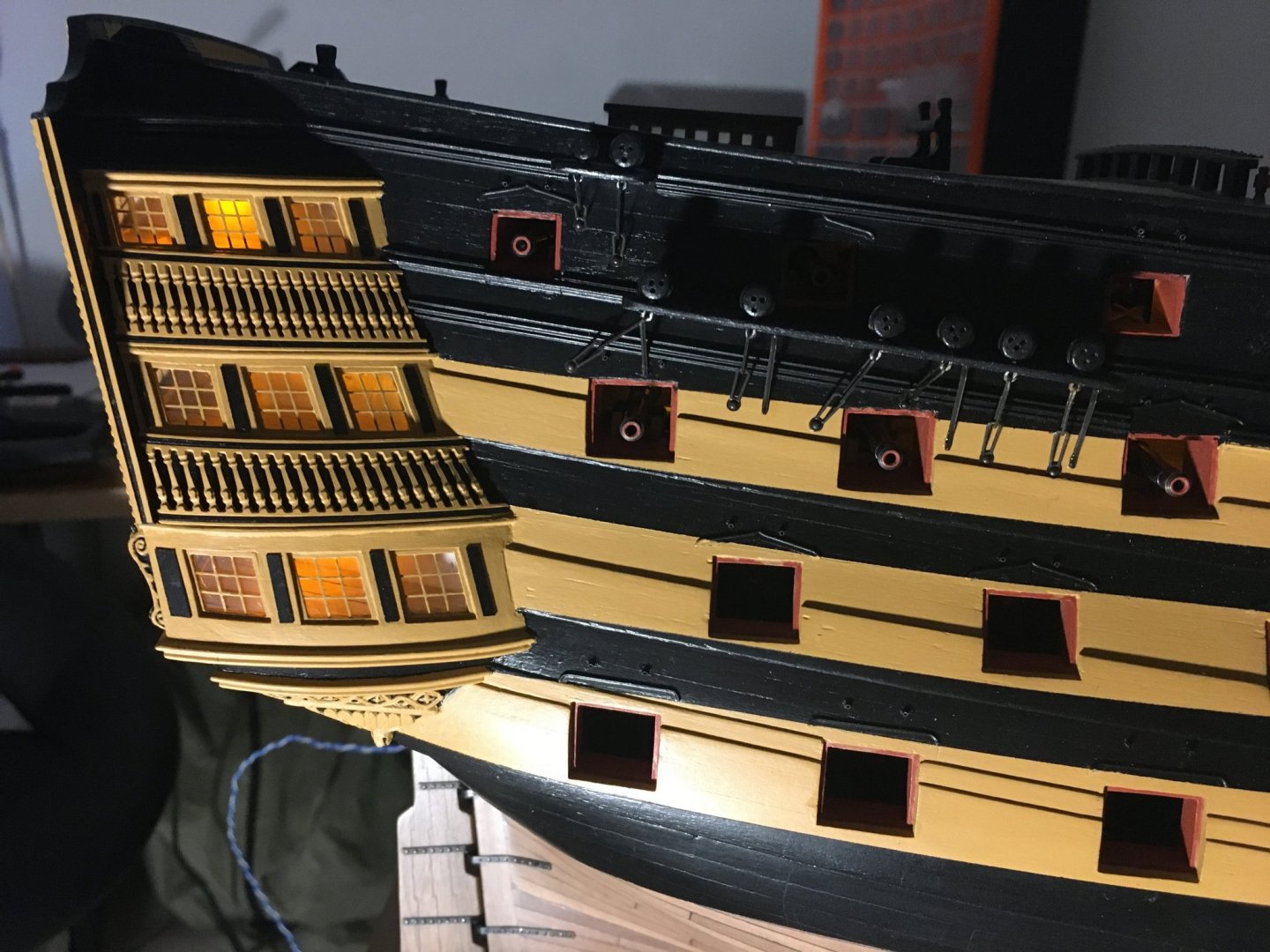
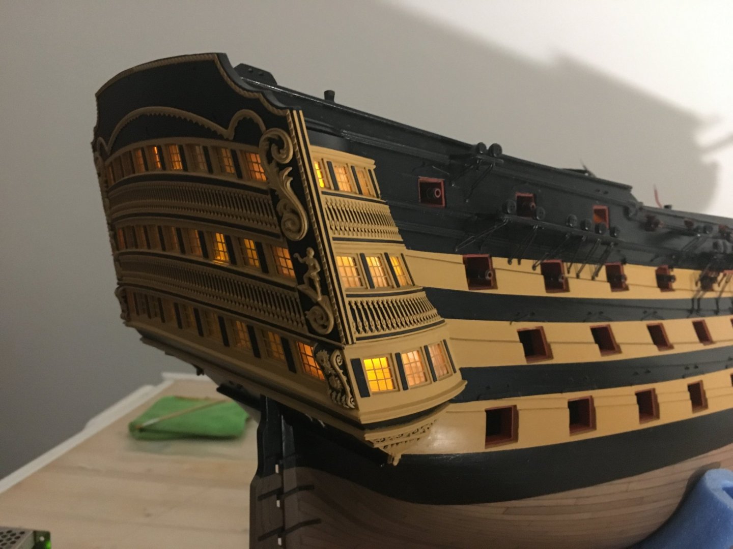
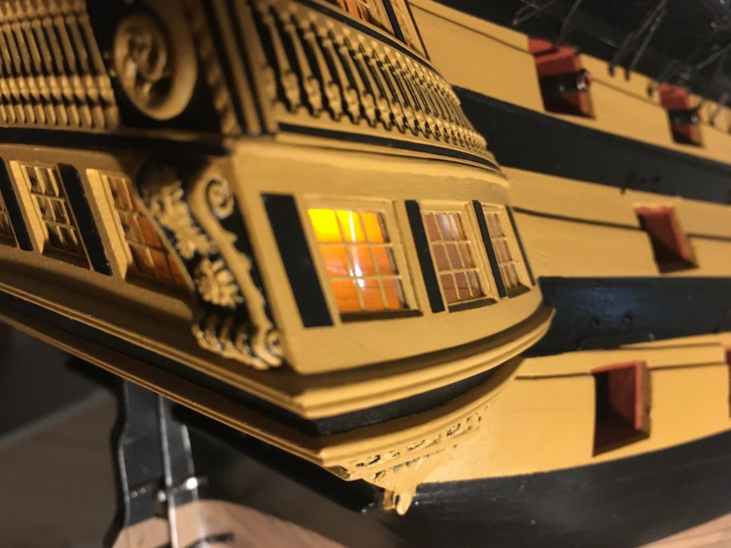
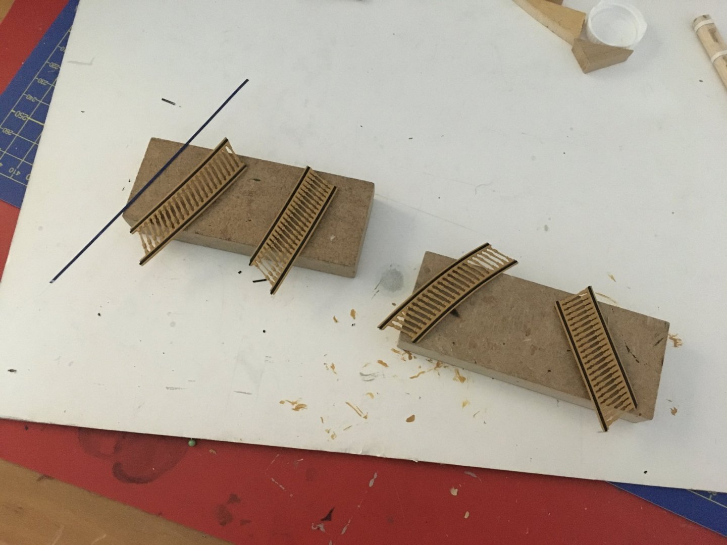
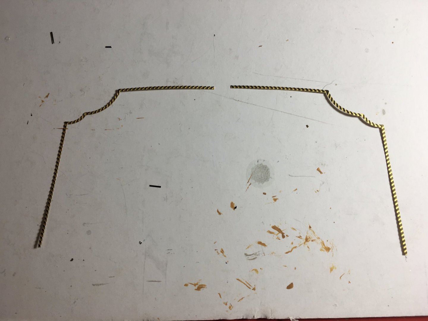
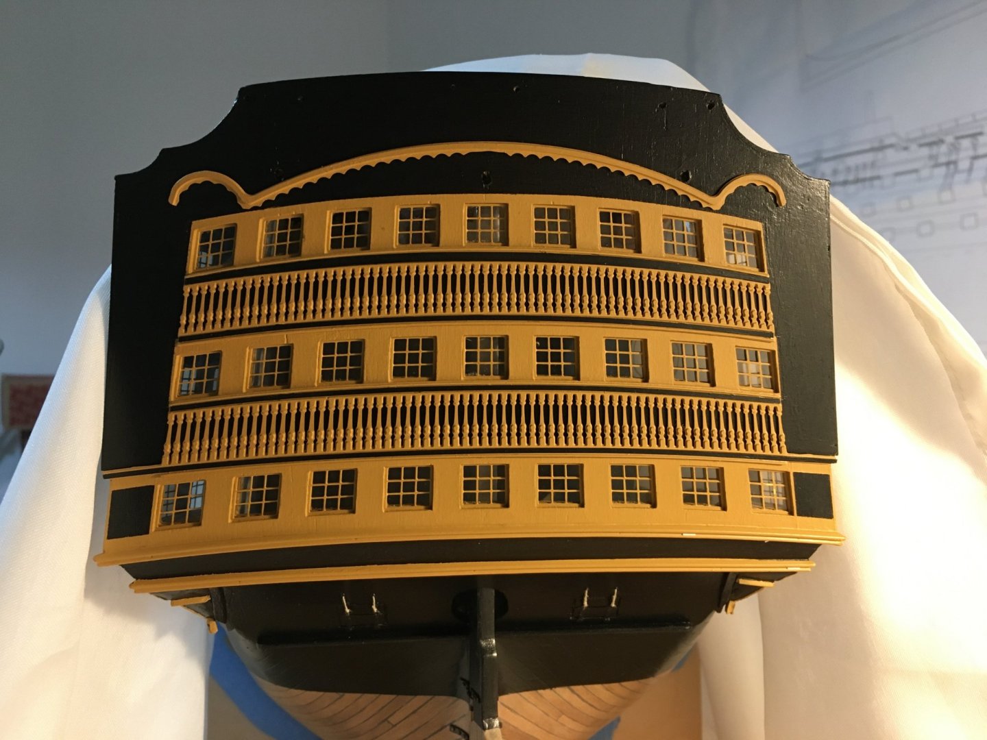
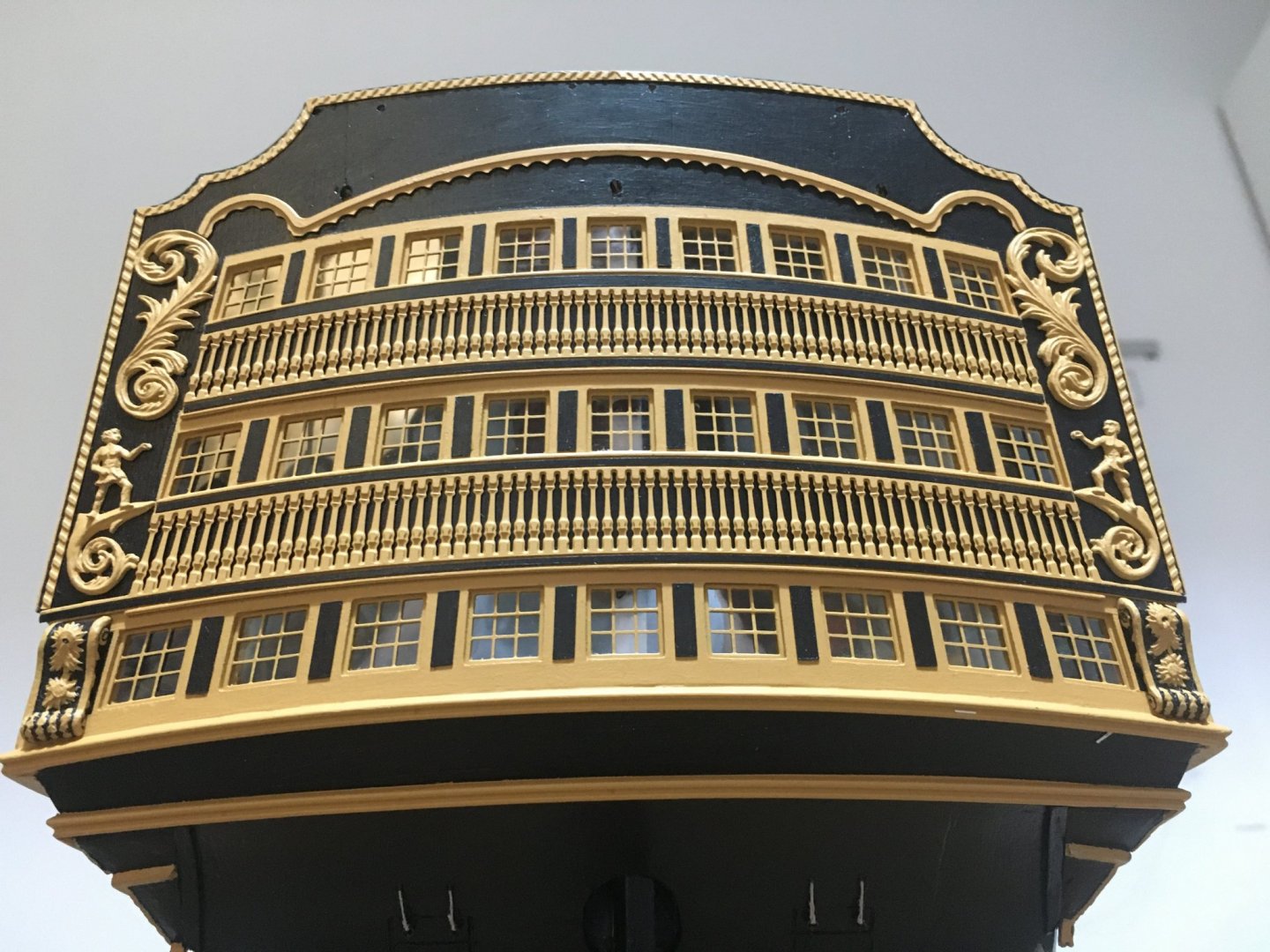
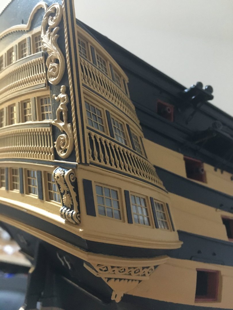
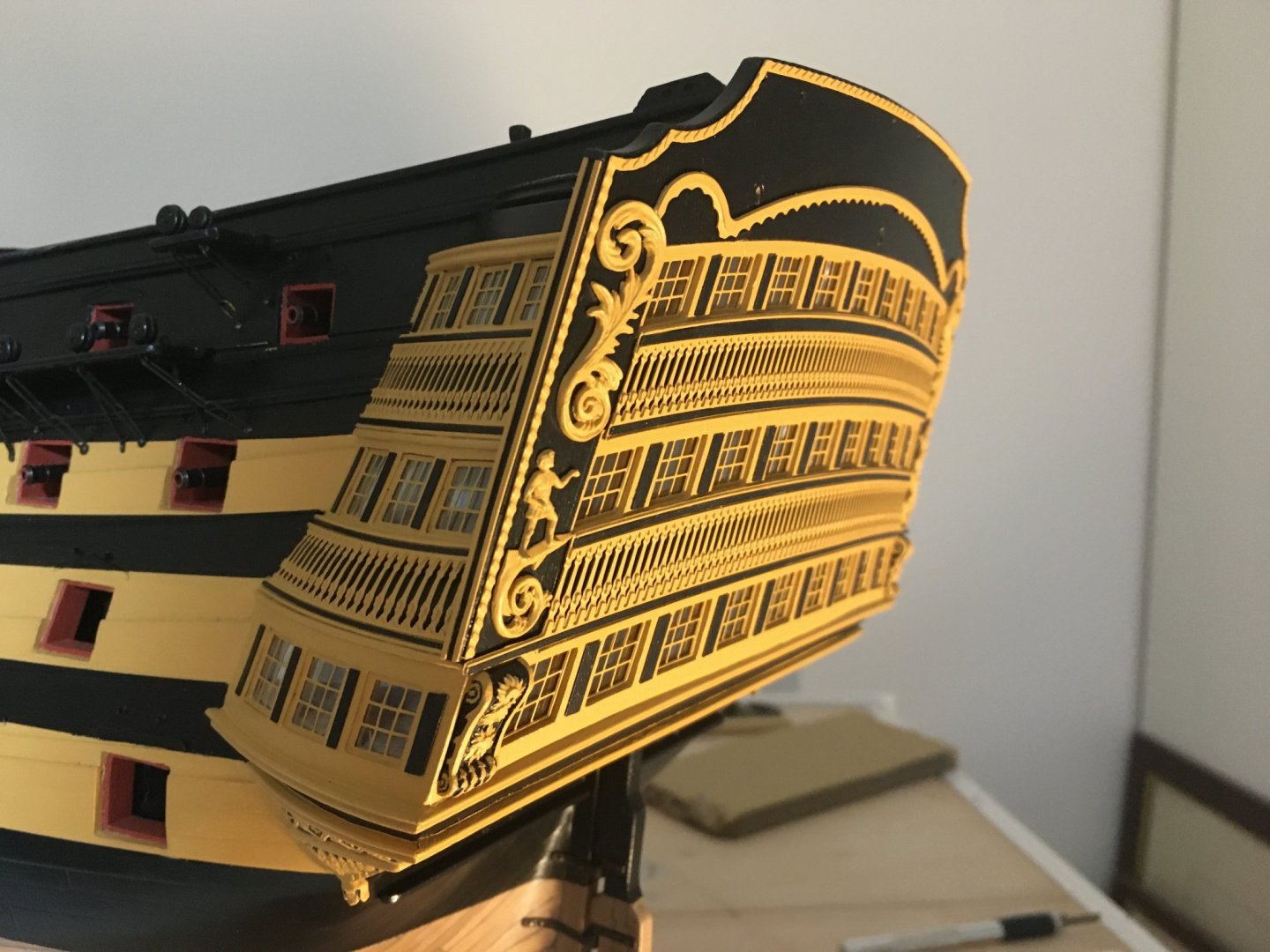
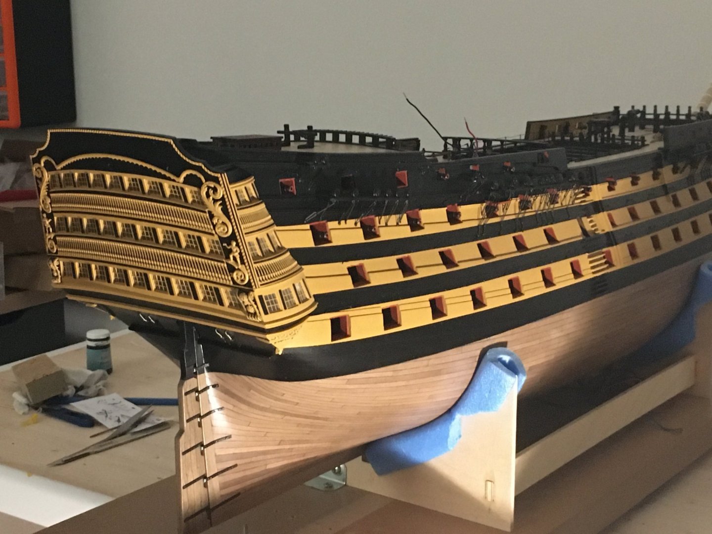
An update of the work on the stern. Painted the stern and gallery baluster patterns. As a primer I used the the VMS 'Metal Prep 4K'. It worked quite good, the acrylic paint adhered much better then the grey primer I had. They had a much better resistance to scratches while handling them. For the black line I used Styrene strips, 0.25 x 1mm for the side galleries, 0.25mm x 2mm for the lower stern baluster pattern. For the upper baluster pattern I used the 2mm for the lower line but the top line is not the same width all the length. In the middle it gets wider, so I used the 5mm strip and trimmed the sides accordingly. Fitted the stern baluster patterns and the top moulding in place. I separated the stern edge fascia edging in two so that I can obtain the exact positioning on the sides of the fascia, otherwise it was going to be too much to the edges of the fascia. Also started fitting the black patterns between the windows. I made them from styrene strips as well. They were quite tedious to make as they are not the same size. Each one you make you have to cut to its require height, top and bottom trimmed slanting, check in place and keep trimming until you get the right size and shape. I had all the white metal stern figures ready and painted. Before you paint them it is important to trim their edges as most of the time they have extra material protruding out. Here are a few photos of all of them fitted except for the trophy of arms and the lanterns. When fitting the stern fascia top moulding you have to make sure you have the space for the coat of arms between it and the edge moulding. For the lanterns I already have the holes ready on the facia. On the edge of the fascia I ran two narrow strips of styrene (0.25mm x 0.75mm) painted yellow before fitting them. Robert


- 527 replies
-
- 9
-
-
- caldercraft
- victory
- (and 1 more)
-
HMS Victory by Helli - Caldercraft
Robert29 replied to Helli's topic in - Kit build logs for subjects built from 1751 - 1800
Hi Helli, Really nice work on the shrouds, very neat and authentic. The rigging is going to be a challenge for me, never attempted a rigging job of the Victory's level. The only rigging I did was on the J.S. Elcano, which was very basic, and Bluenose II which again is far from the Victory rigging. Robert -
Hello David, welcome to this great forum. I can see that you have already been given some sound advise. Yes, keep away from banned manufacturers, you will not find any builds in this forum relating to these manufacturers. The first thing I realised I needed when I started this hobby was a head magnifier to be able to handle the tiny parts, without them I am lost. I started this hobby about ten years ago and I am currently building the HMS Victory from Caldercraft. But before I started on this ambitious build I tried my hands on a much smaller boat, 'Bluenose II' by Artesania Latina, which is a much more basic build but I must admit, from it I gained a lot of experience regarding hull and deck planking, plank bending and rigging. I think Meddo's advise above is a good one. Regards Robert
-
HMS Victory by Helli - Caldercraft
Robert29 replied to Helli's topic in - Kit build logs for subjects built from 1751 - 1800
Hi Helli, I just came across your build, I don't know how I have missed it during all this time. That's a great job you are doing on the rigging. I agree with you about the two books you recommended to Vahur, I have both of them. When I came to do the masts, which I am still working on, I deviated a bit from the plans supplied with the kit and referred a lot to 'The Anatomy of Nelson's Ships'. It has some great drawings on the masts and rigging. I haven't started the rigging yet, and I am sure I will be referring a lot to these two books, and your build to steal some ideas 🙂. Robert -
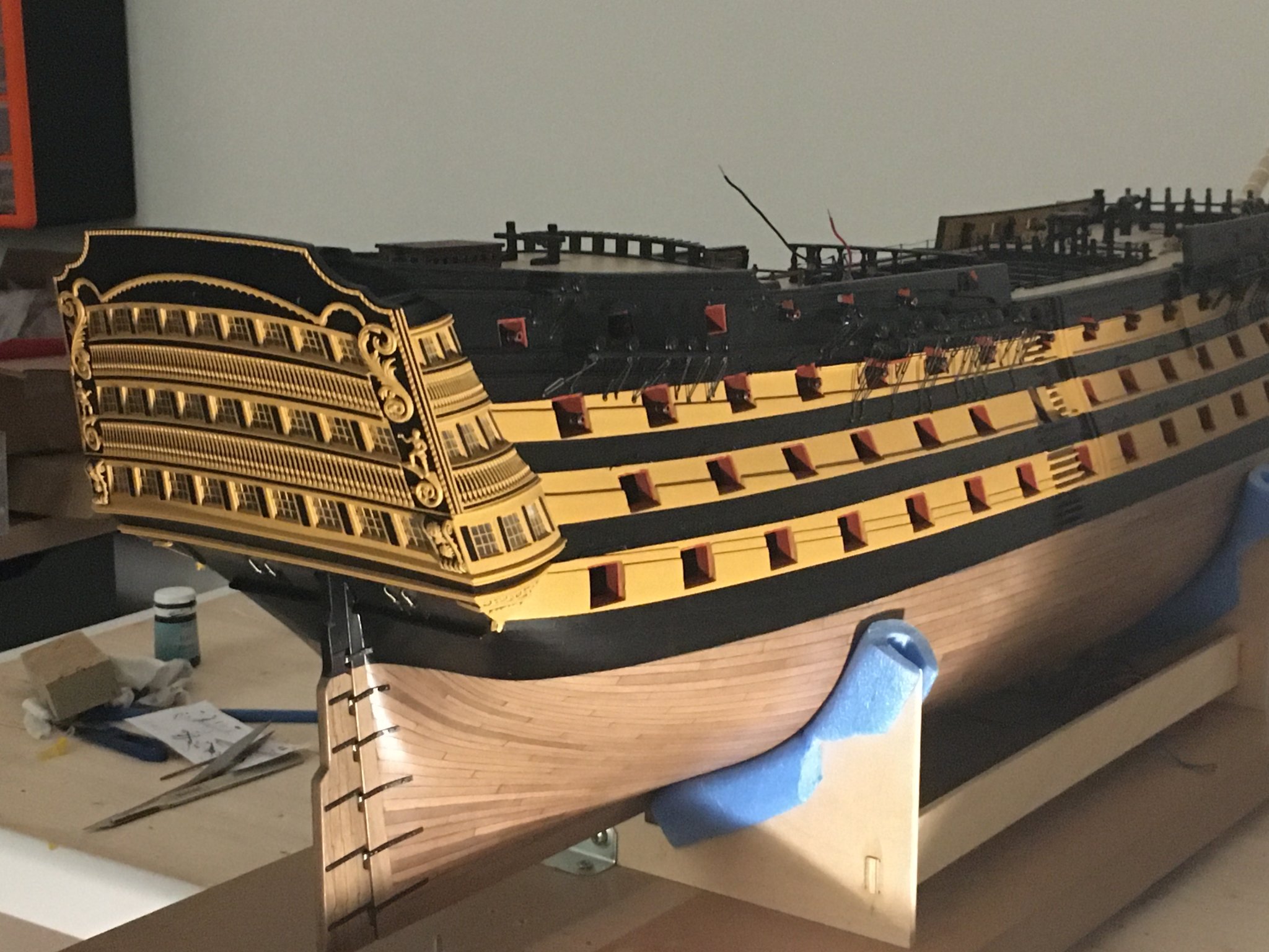
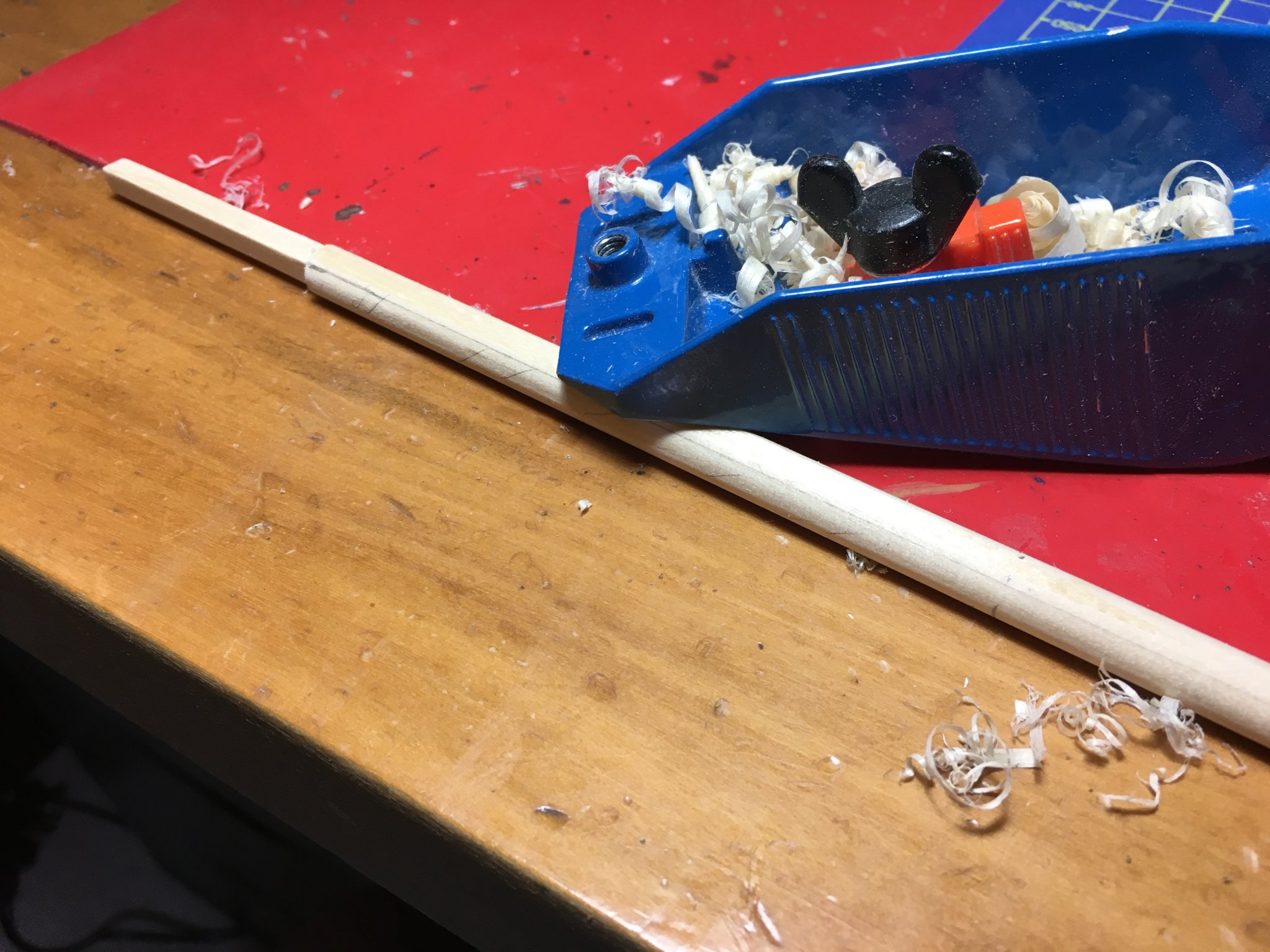
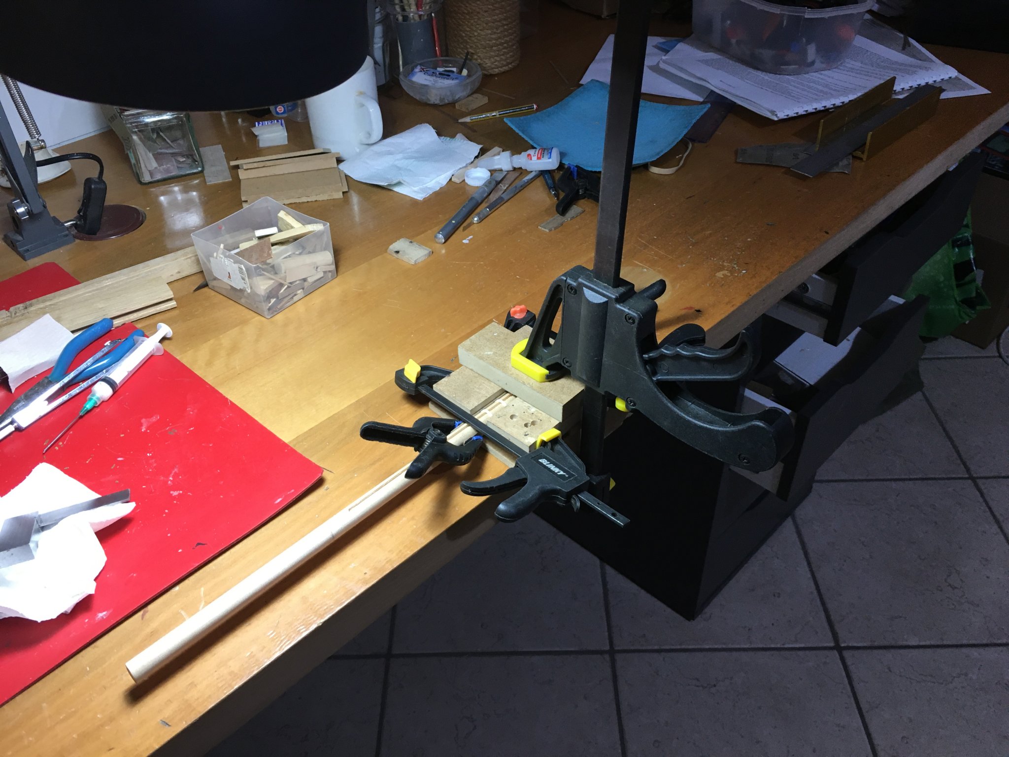
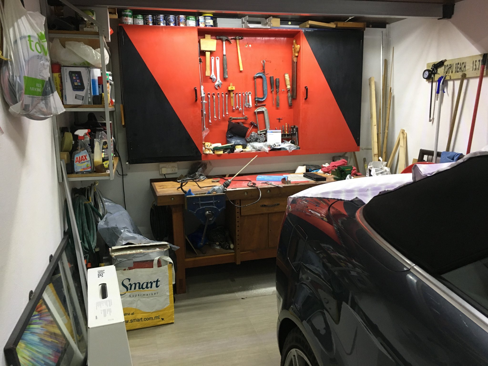
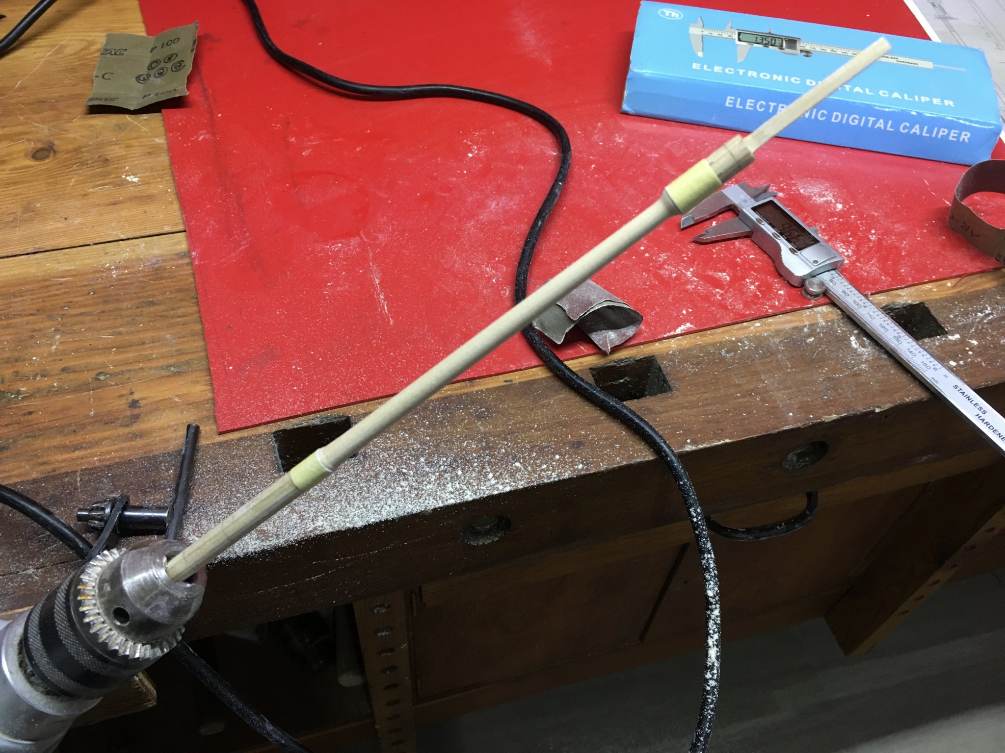
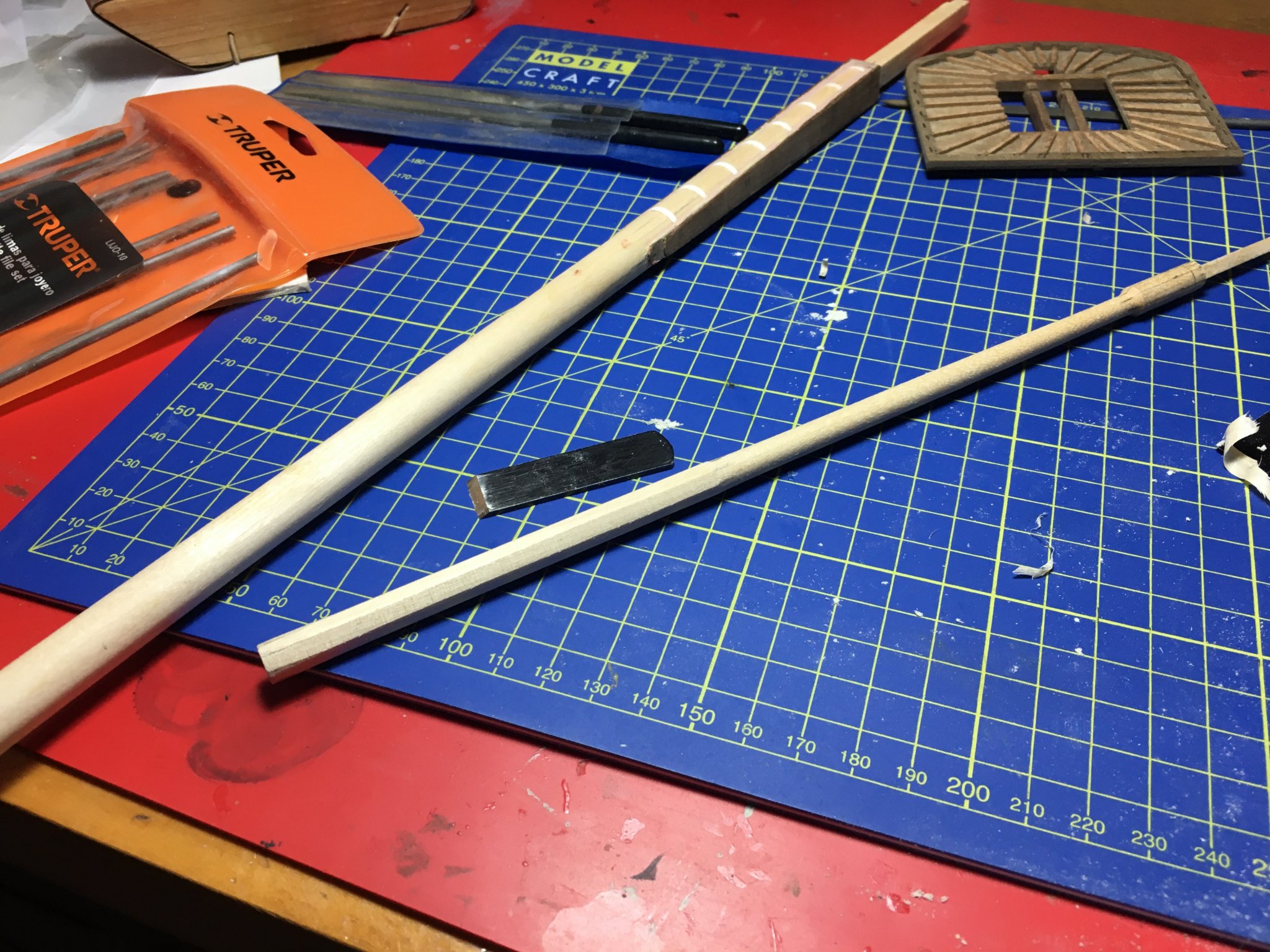
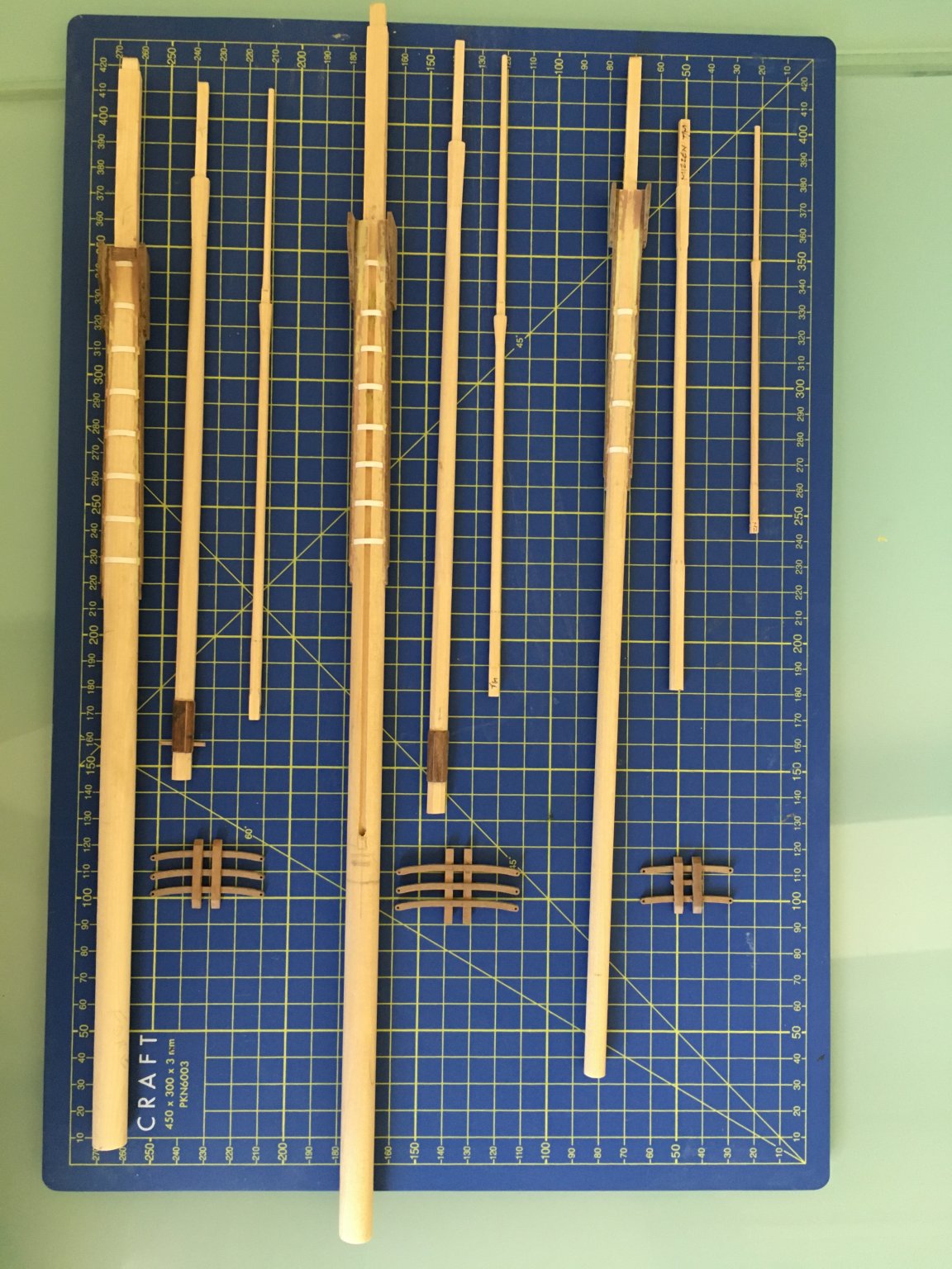
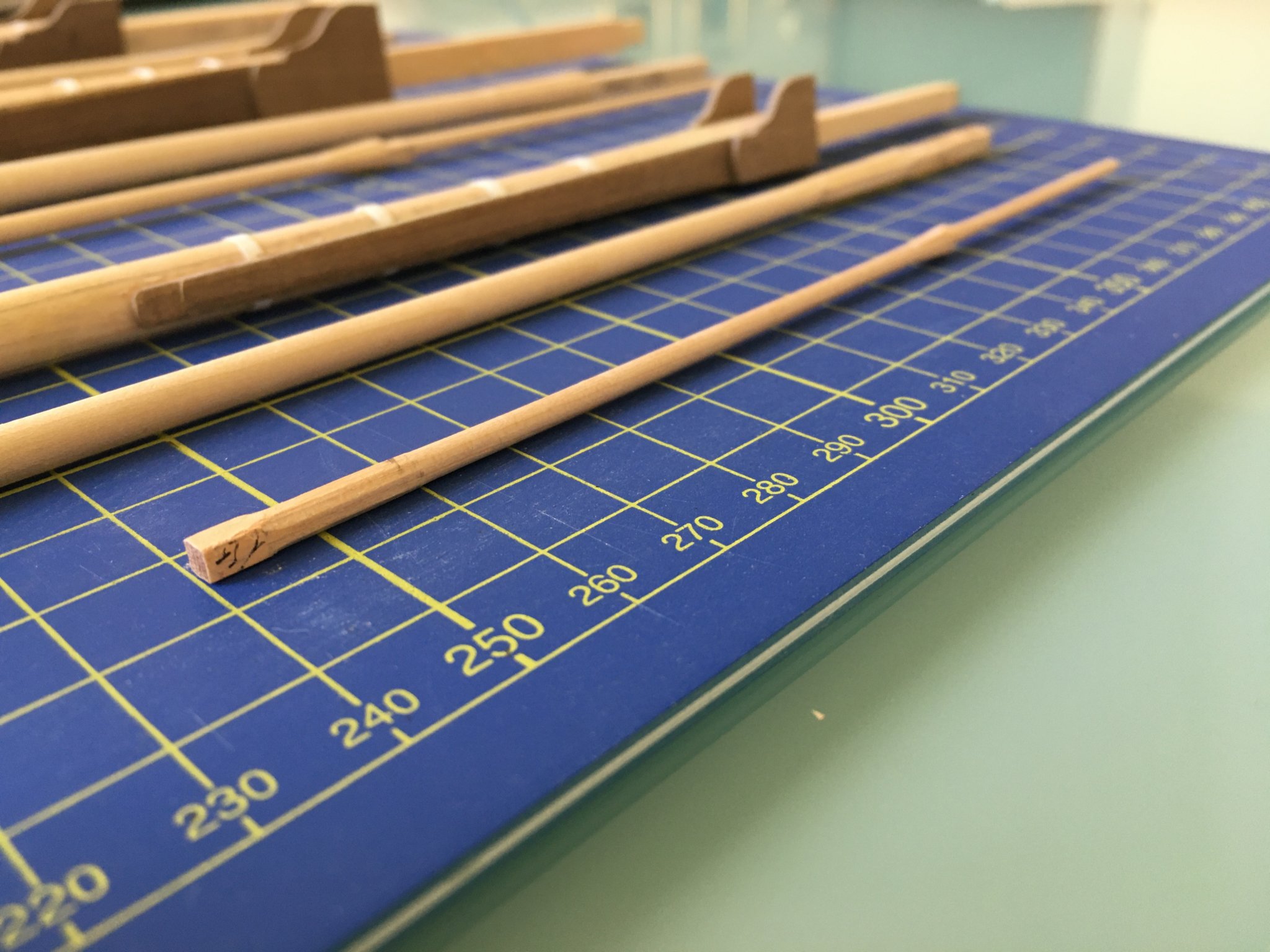
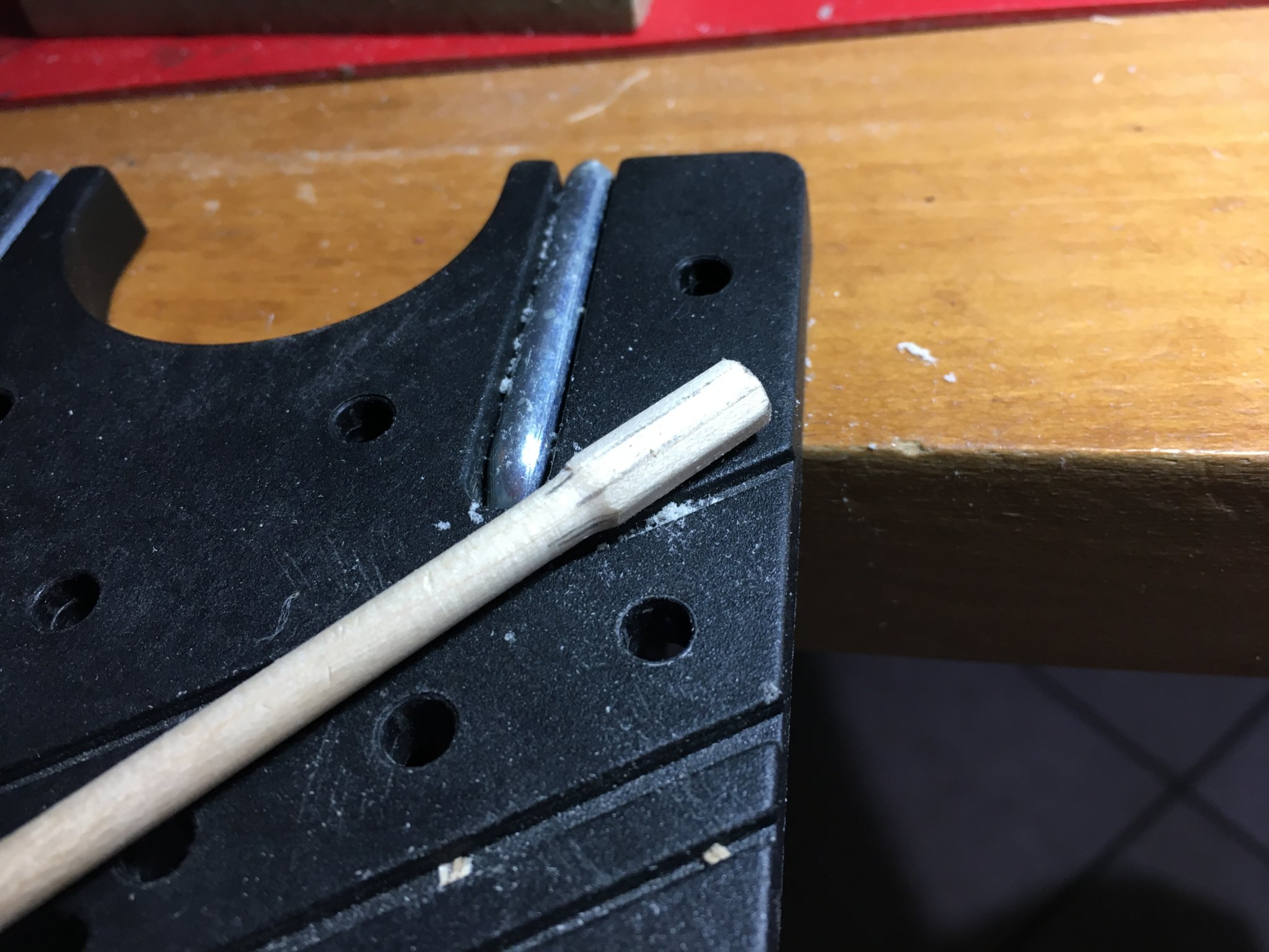
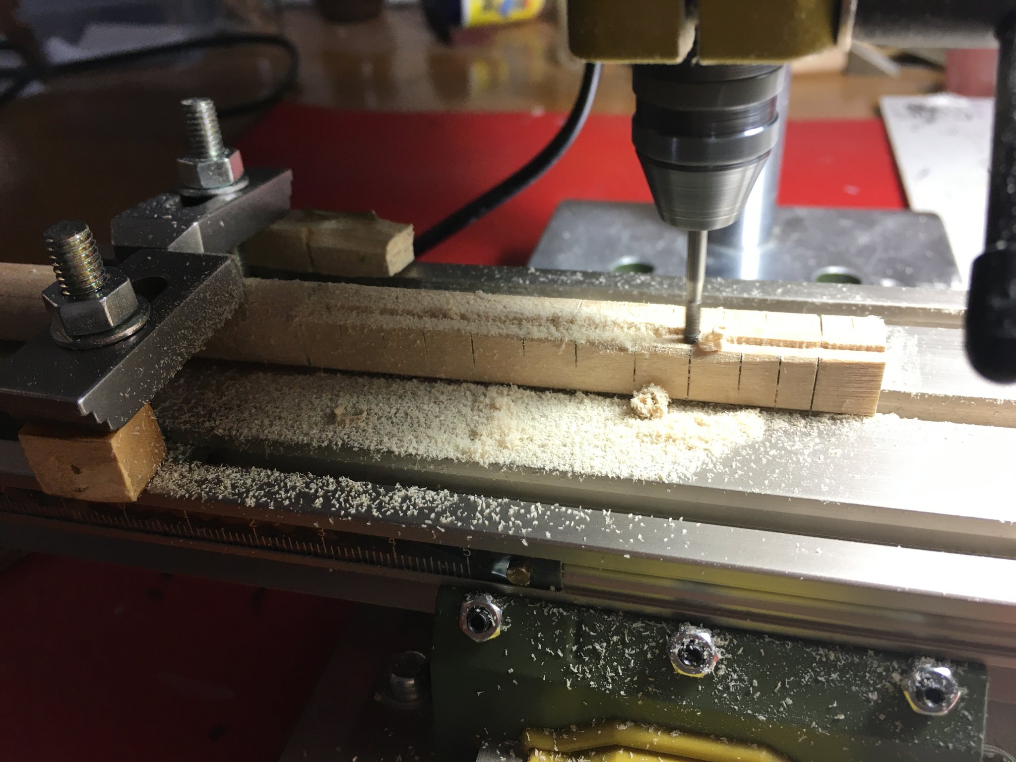
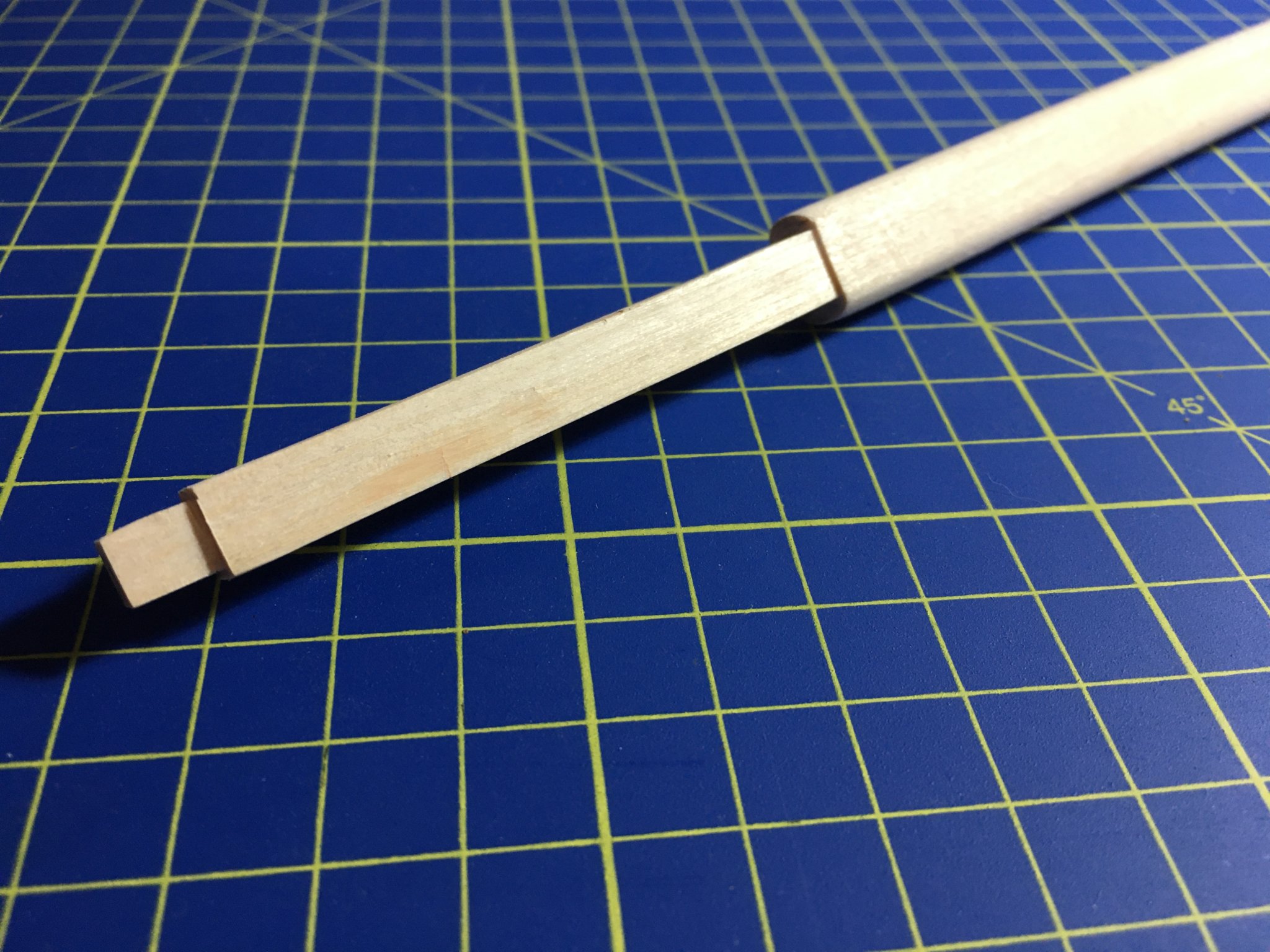
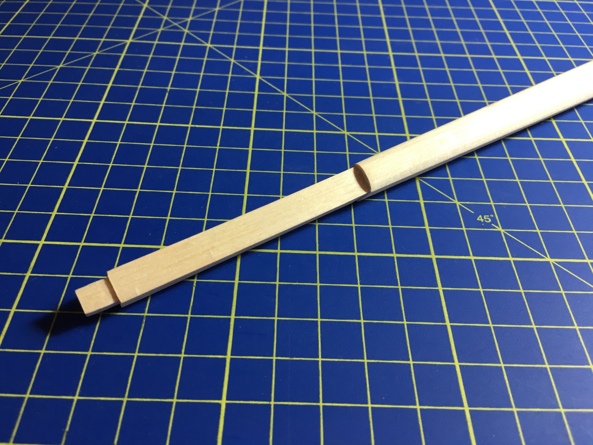
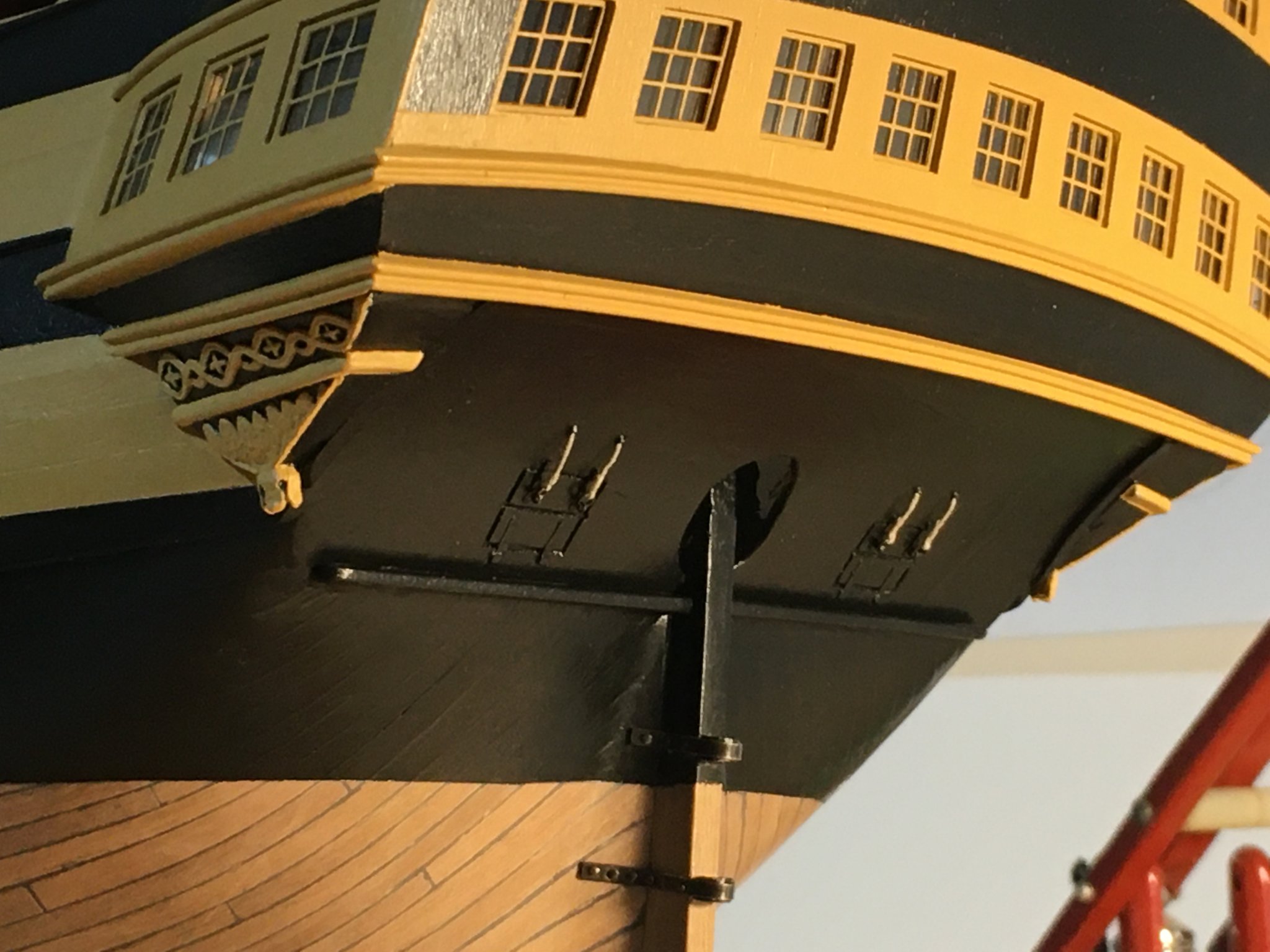
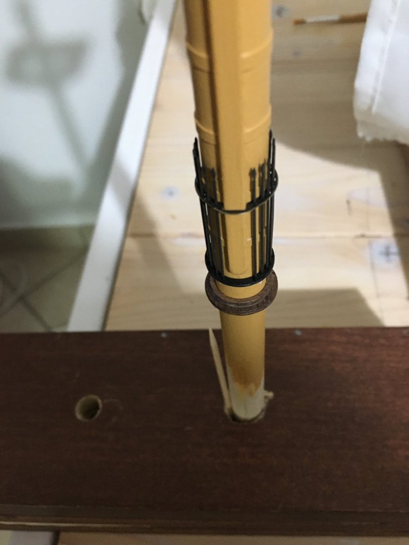
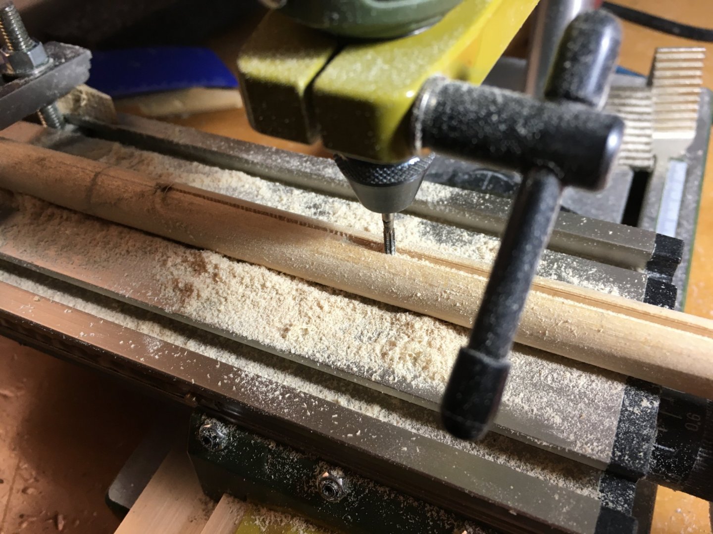
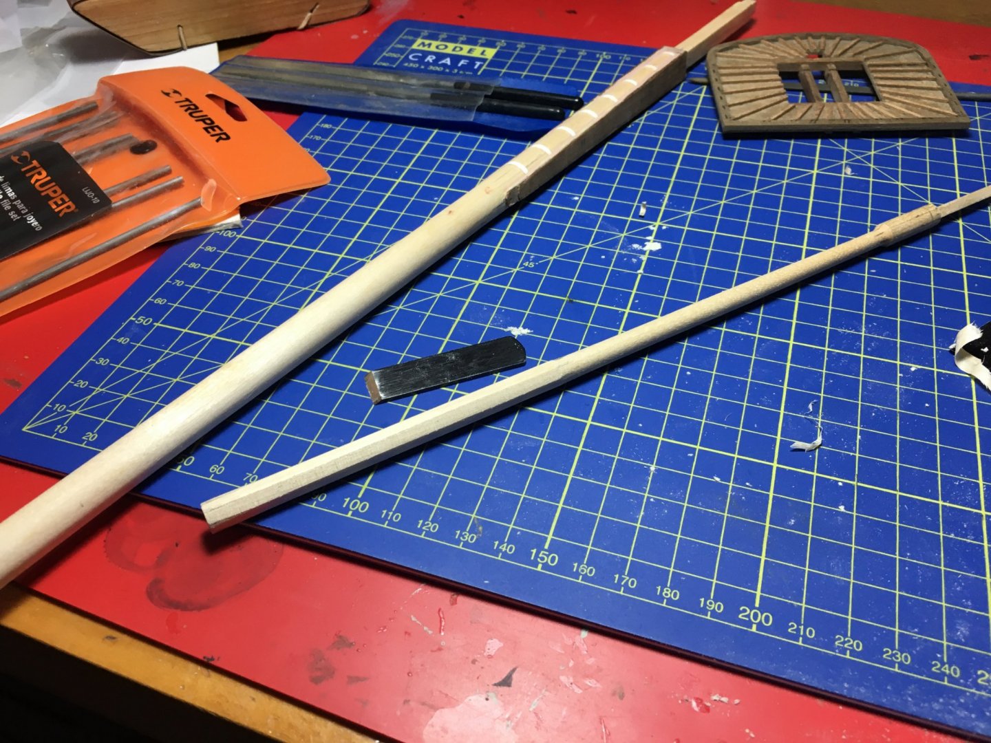
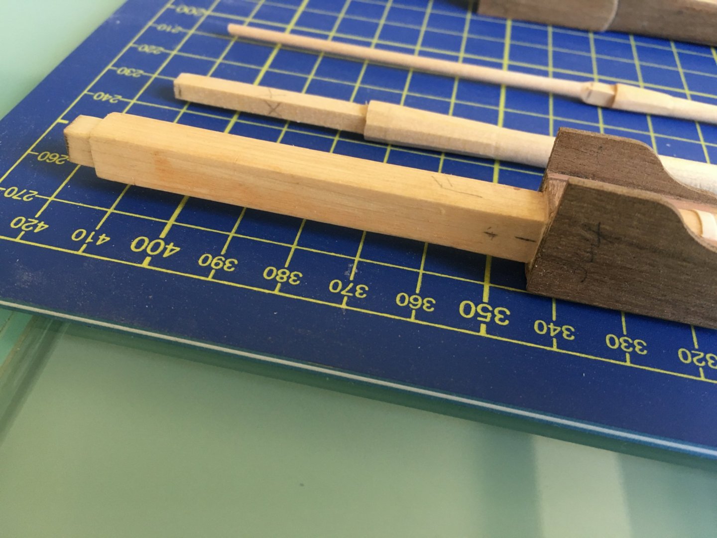
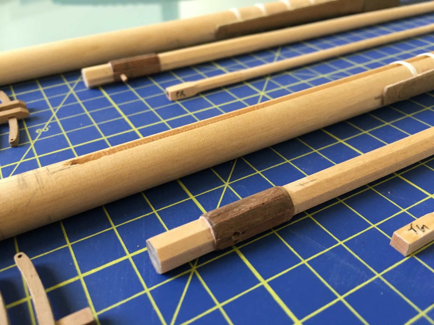
Stuglio, thanks for your encouraging comments. To copper or not to copper the hull was a decision which took me long to decide. Heinz, thank you, I must say browsing through your Victory build gives me a lot of encouragement. md1400cs, thank you, I myself took loads of ideas from other builds. Finally I received the long awaited product I was waiting for to treat the brass before painting with acrylic paint, so now I will put aside the work I was doing on he masts to continue the work on the stern. But I will give you an update were I have arrived on the masts. Tapering and flattening the sides of the lower masts with a plane and sanding to take the cheeks. Fitted the bands which have to pass through from under the cheeks. I used styrene 0.25mm x 2mm. This is the main lower mast. It's the one that has a lantern fitted to the lower top. I cut a channel along the mast through which I will pass the wires to supply the led in the lantern. After I pass the wires the channel will be filled and on top of it will be fitted the rubbing paunch, so no wiring will be exposed. Hopefully I will manage to solder the wires to the wires at the base of the mast without leaving any showing. Using grips to keep cheeks in place while the glue dries dries. Once the lower masts were formed I started work on the top masts and topgallant masts. First I marked the octagons on them all along the dowel. Then I squared the ends were they needed to. Before shaping the octagons I tapered the parts where the dowel was to remain round. At this stage I had a bit of difficulty in the octagon measurements given on the kit's plans. On the plans the measurements for the octagons were given from one corner point to the other. If you work like that there were instances were the octagon measurement from one face to the other was going to be thinner than the rounded mast on top of it. Not only it does not look good but I think it is wrong. The octagon should be larger than the rounded part on top of it. So basically I diverted a bit from the measurements given on the plans, especially were the octagons were involved. I have the book by C. Nepean Longbridge ' The Anatomy of Nelson's Ships'. which was of great help in this regards. It has some pretty detailed drawings with measurements of the masts. I do not own a lathe and I did the tapering on a power drill. Because of the amount of saw dust I did this in my garage. I have a variable speed driller with I grabbed in a bench vice and used sand paper to taper them taking care not to touch where the octagons should be. I marked these with a piece of masking tape. I used course sand paper to remove the bulk, then change to finer sand paper when it gets near the required size. A calliper is a must for this work. When the round tapering was done I worked on the octagons. You have to be careful to keep one of the flat sides in line with a flat side of the squared part of the mast. To shape them I used a small plane and a small file. I avoided using sand paper as with sand paper it is difficult to have the sharp corners forming the octagon. Sand paper has the tendency to round off the corners on such small diameters and loosing all the effect of the octagons. All masts shaped. You can notice that the octagon part on the lower part of two masts, where it is offset, I shaped it by adding strips on the underlying octagon and shaping them again. I did this because if I had to make this out of the dowel itself, a lot of material should be removed and the octagon underlying it would have to be smaller, which in turn will be thiner than the rounded part on top of it. I am not sure if I am confusing you, but if you want I can try to explain it with some drawings. Regards Robert


- 527 replies
-
- 9
-
-
- caldercraft
- victory
- (and 1 more)
-
Hi Daniel, I am currently building the Caldercraft Victory and I follow a few other Victory builds on this forum. But to be honest with you, since your build is the plastic kit I never checked on it, thinking its a totally different story from what I am doing. Today I had a look in it and oh boy, was I wrong!!! Your work is amazing, so much detail, your approach to certain problems, simply awesome. I will be following your build with great interest. Robert
-
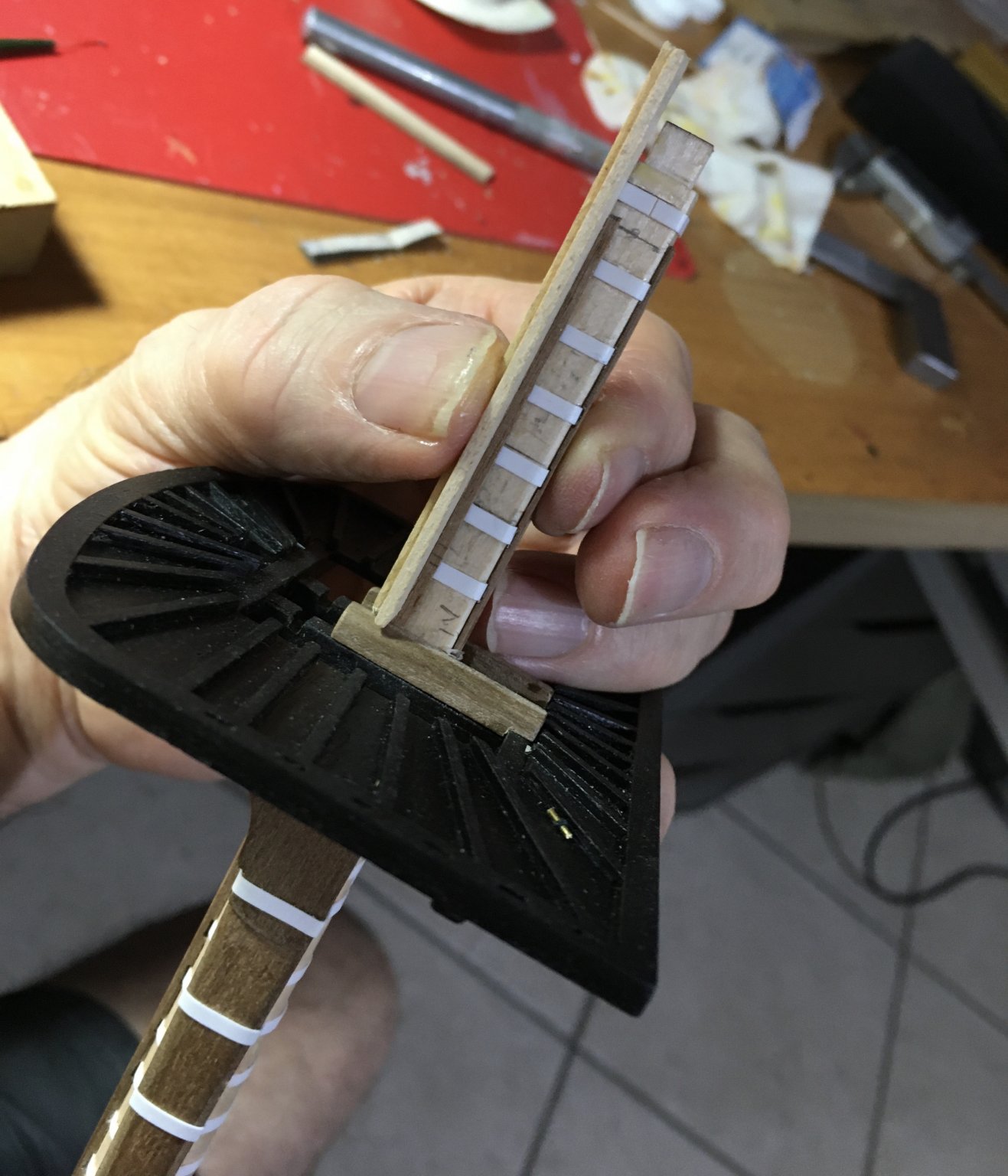
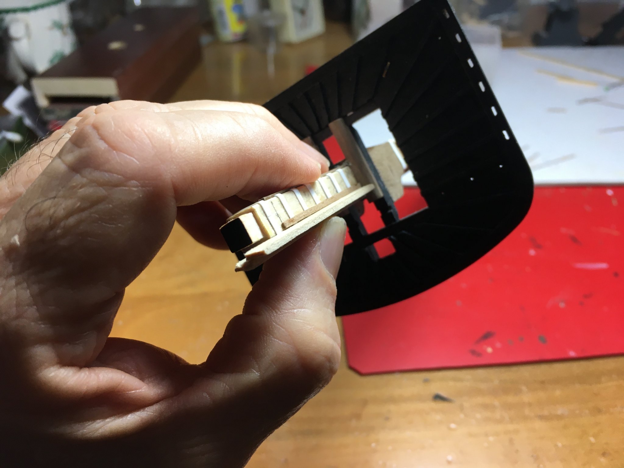
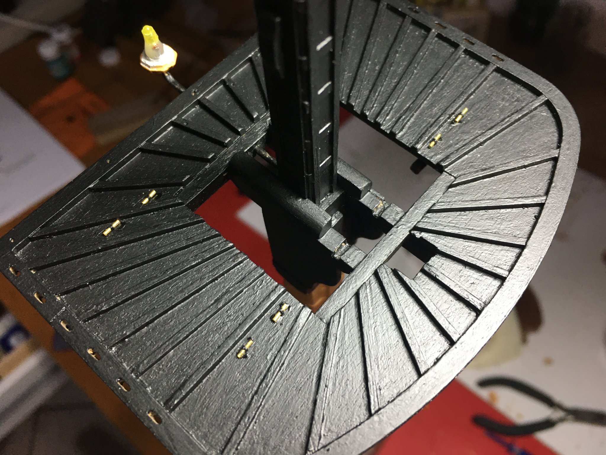
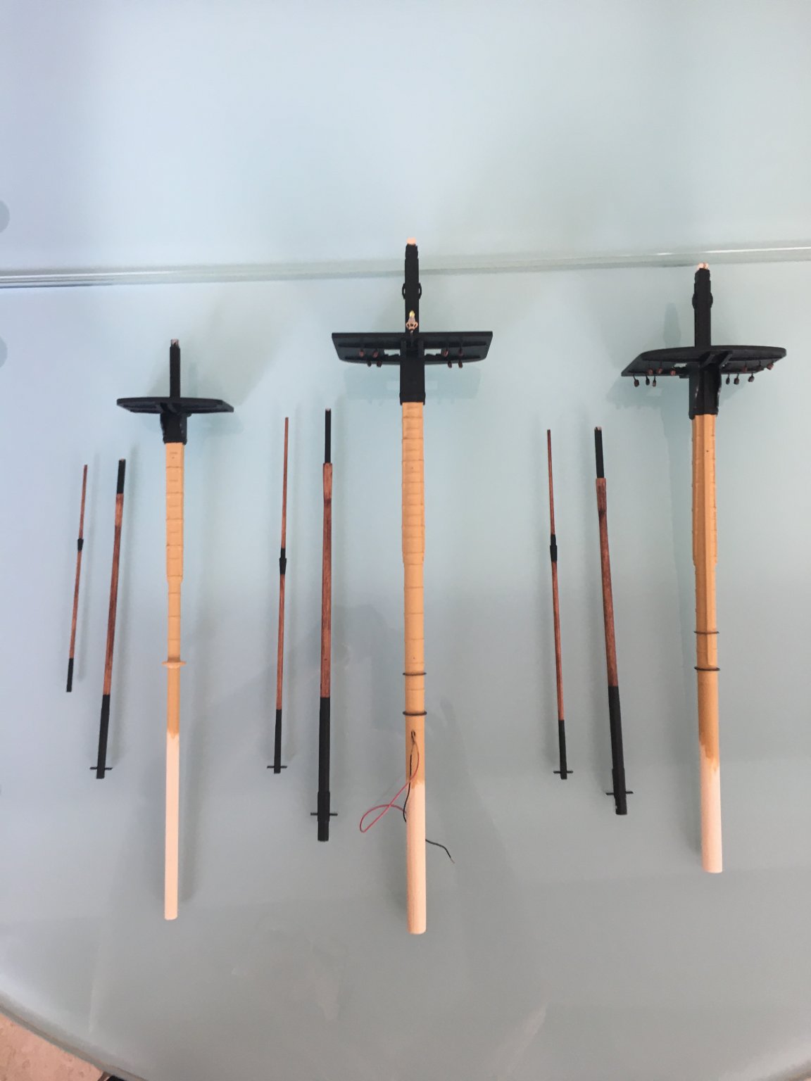
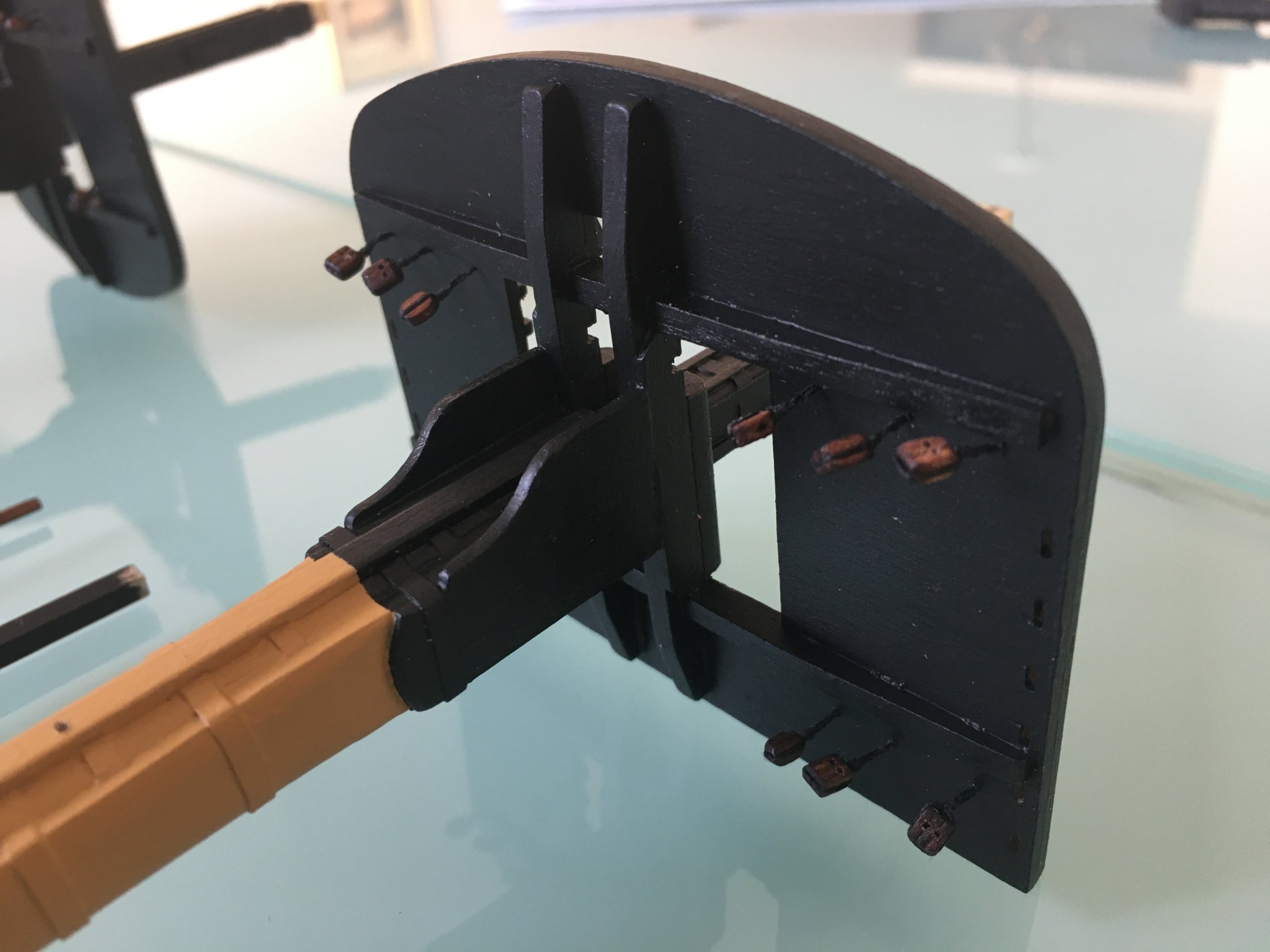
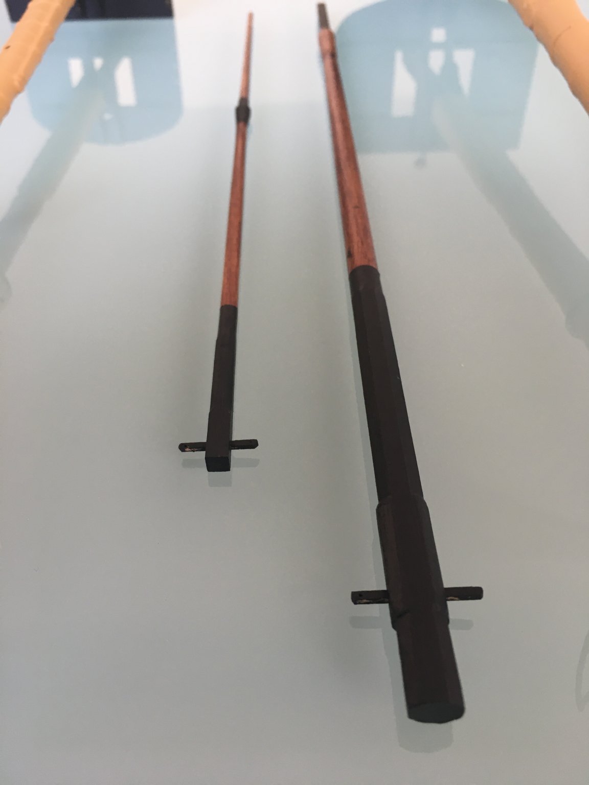
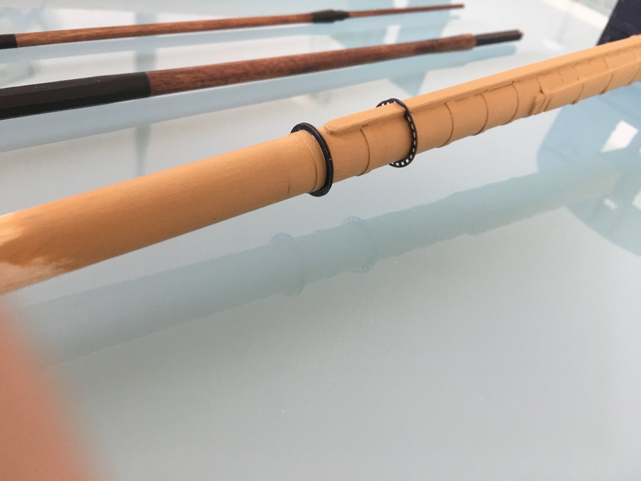
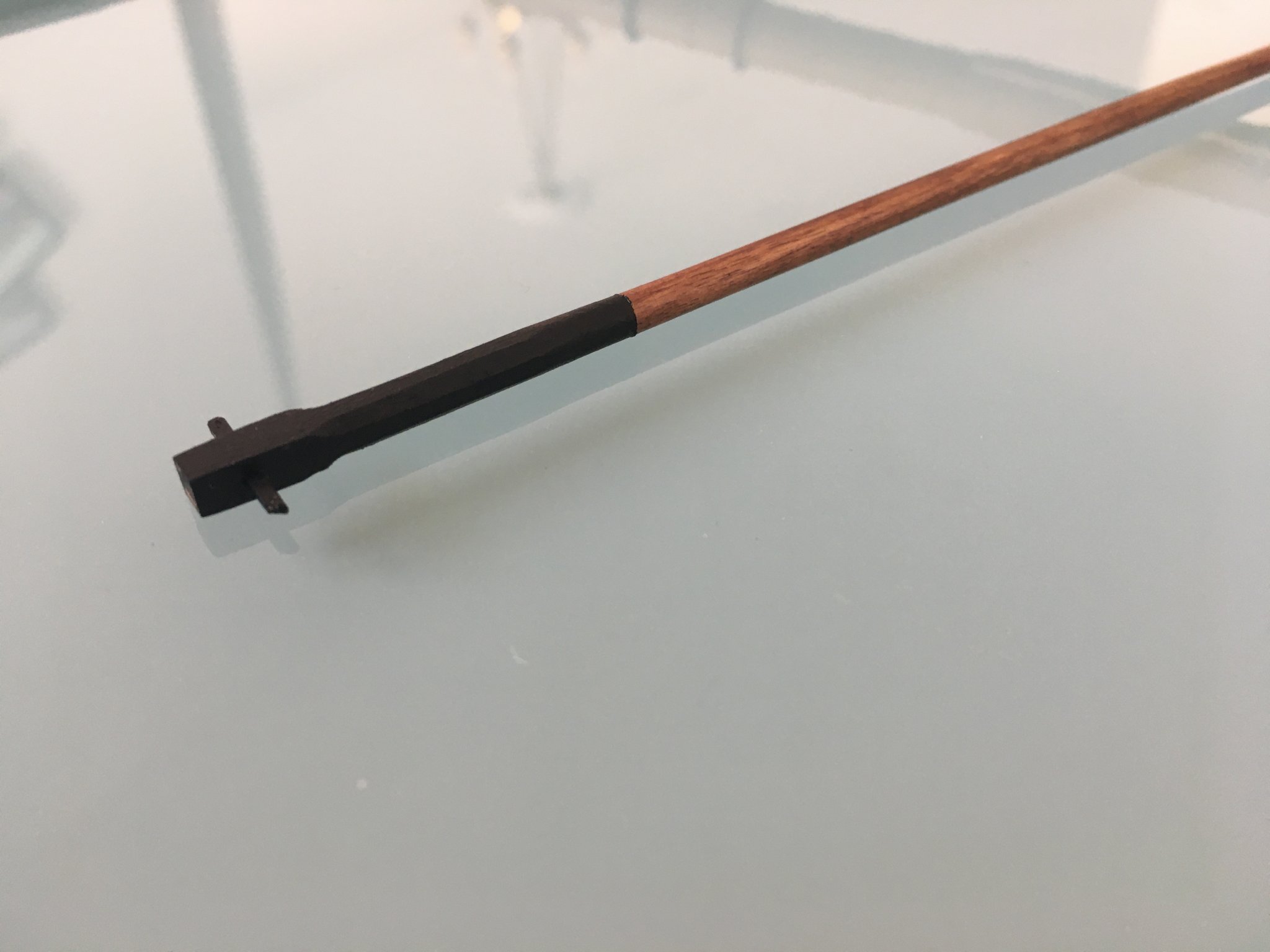
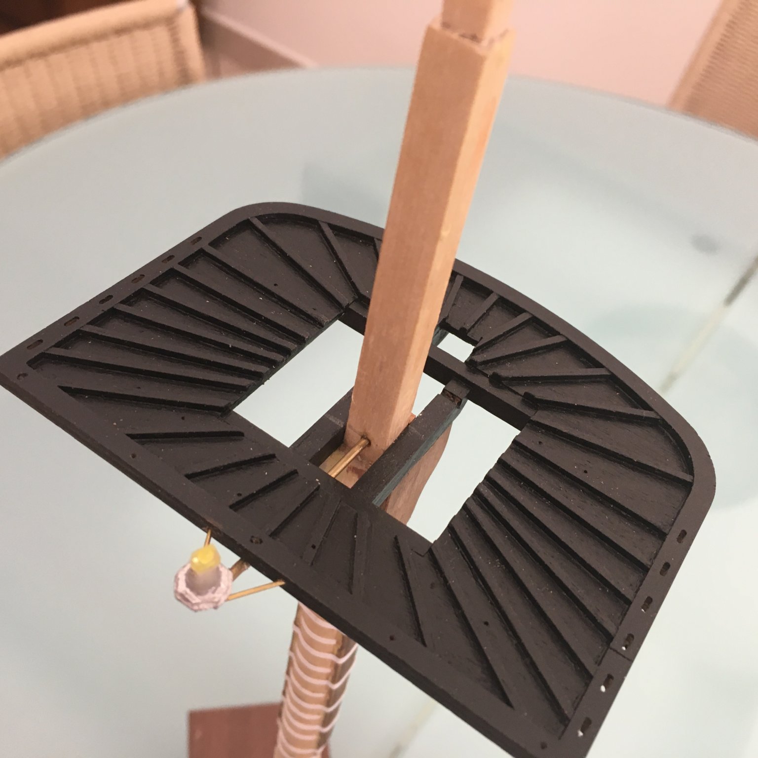
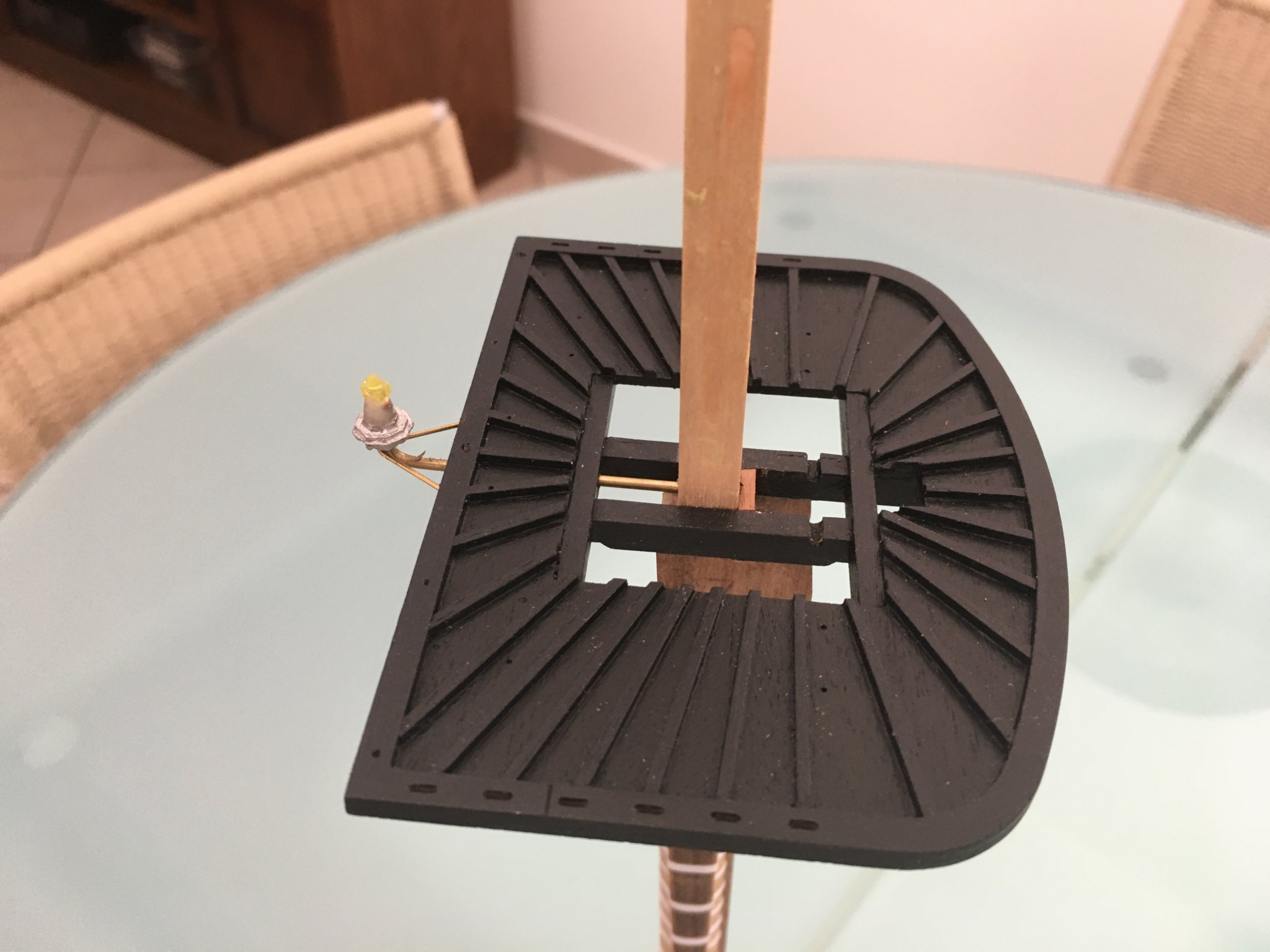
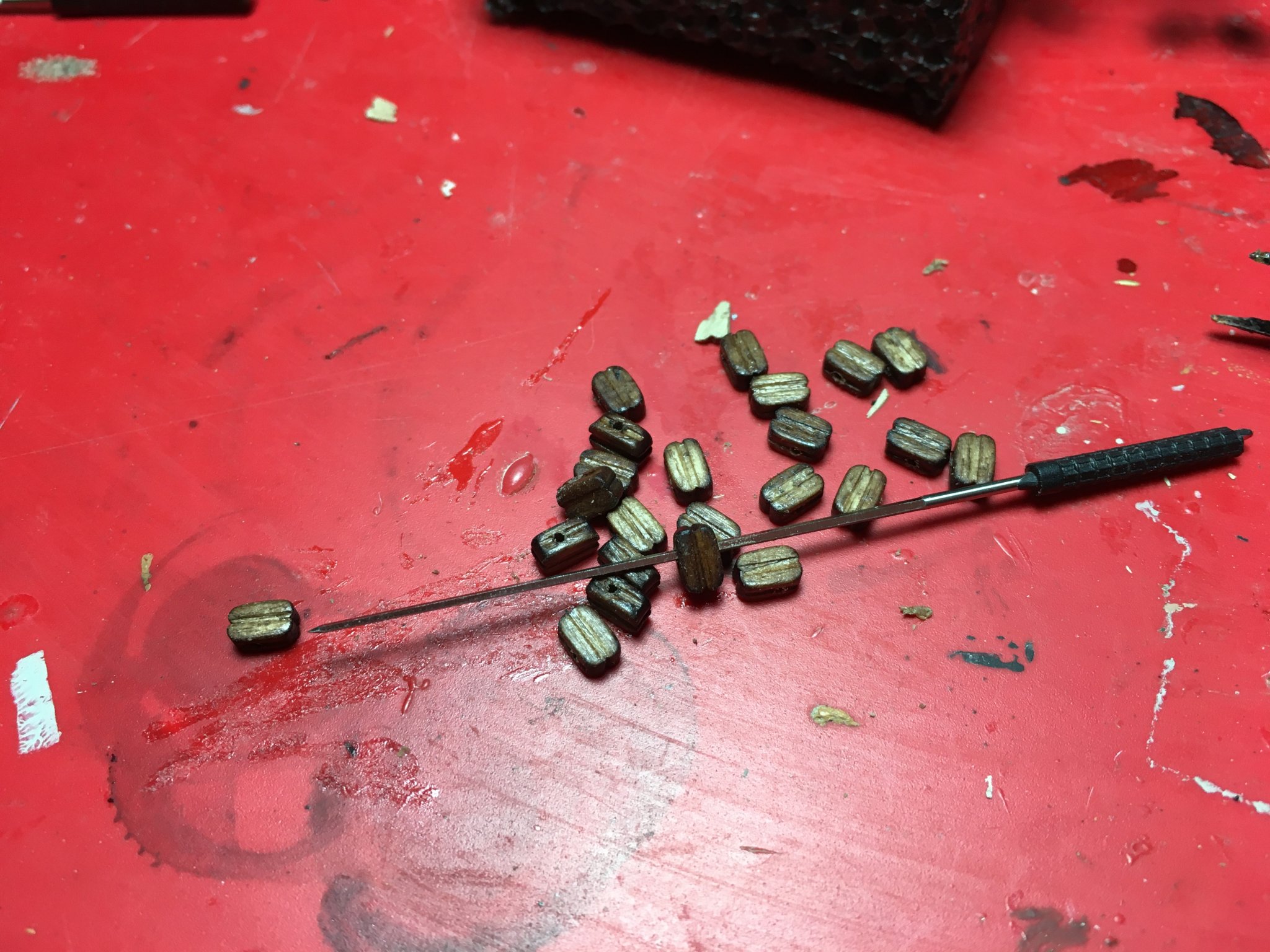
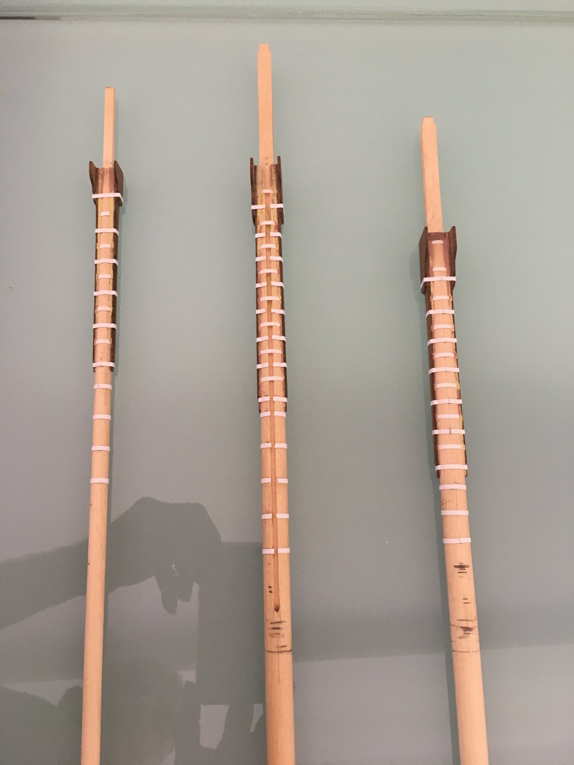
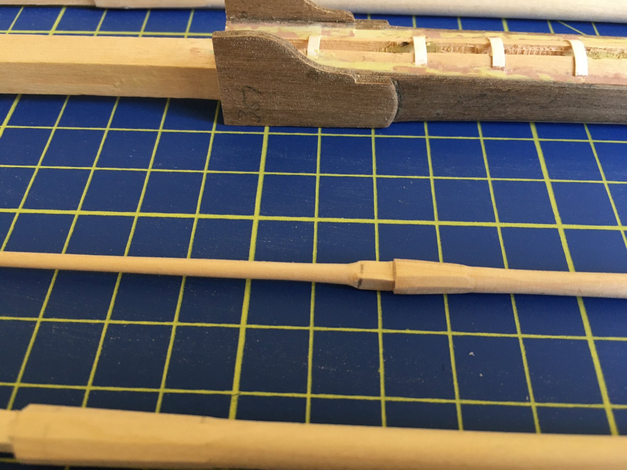
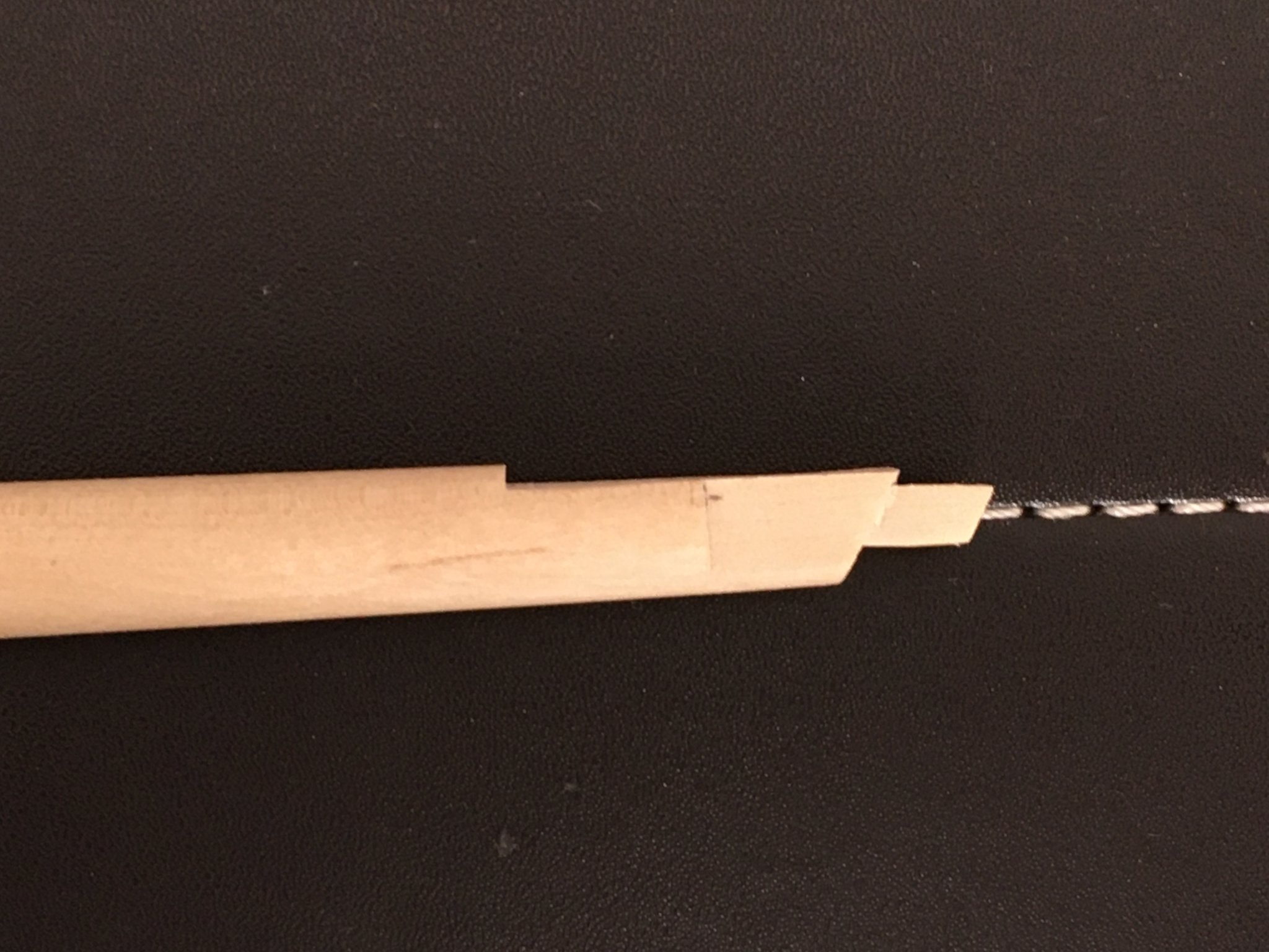
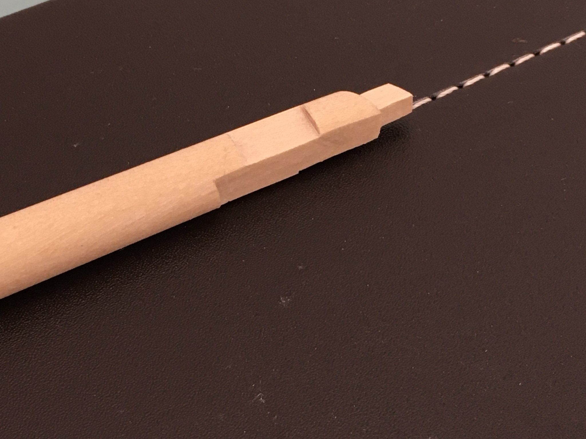
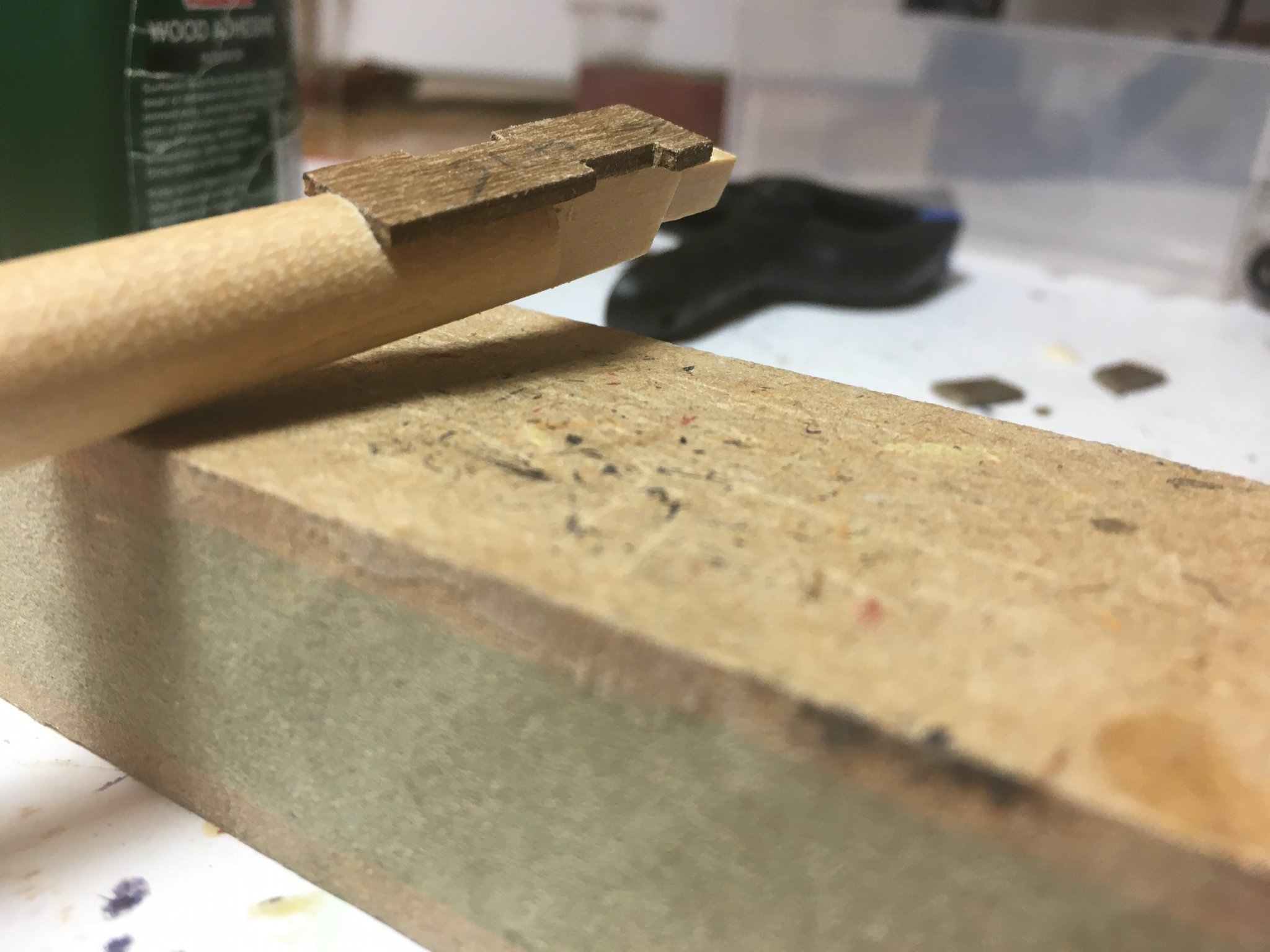
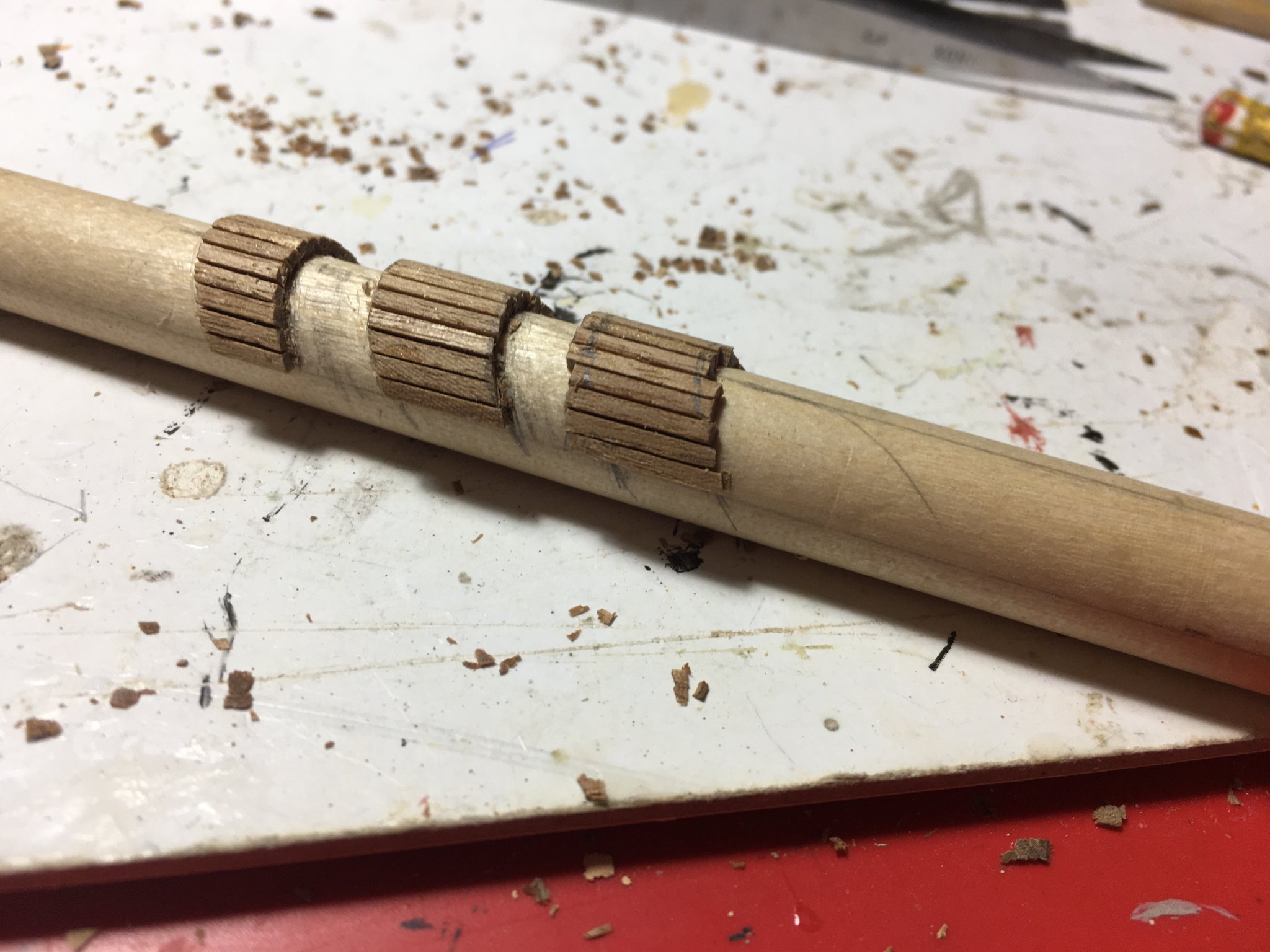
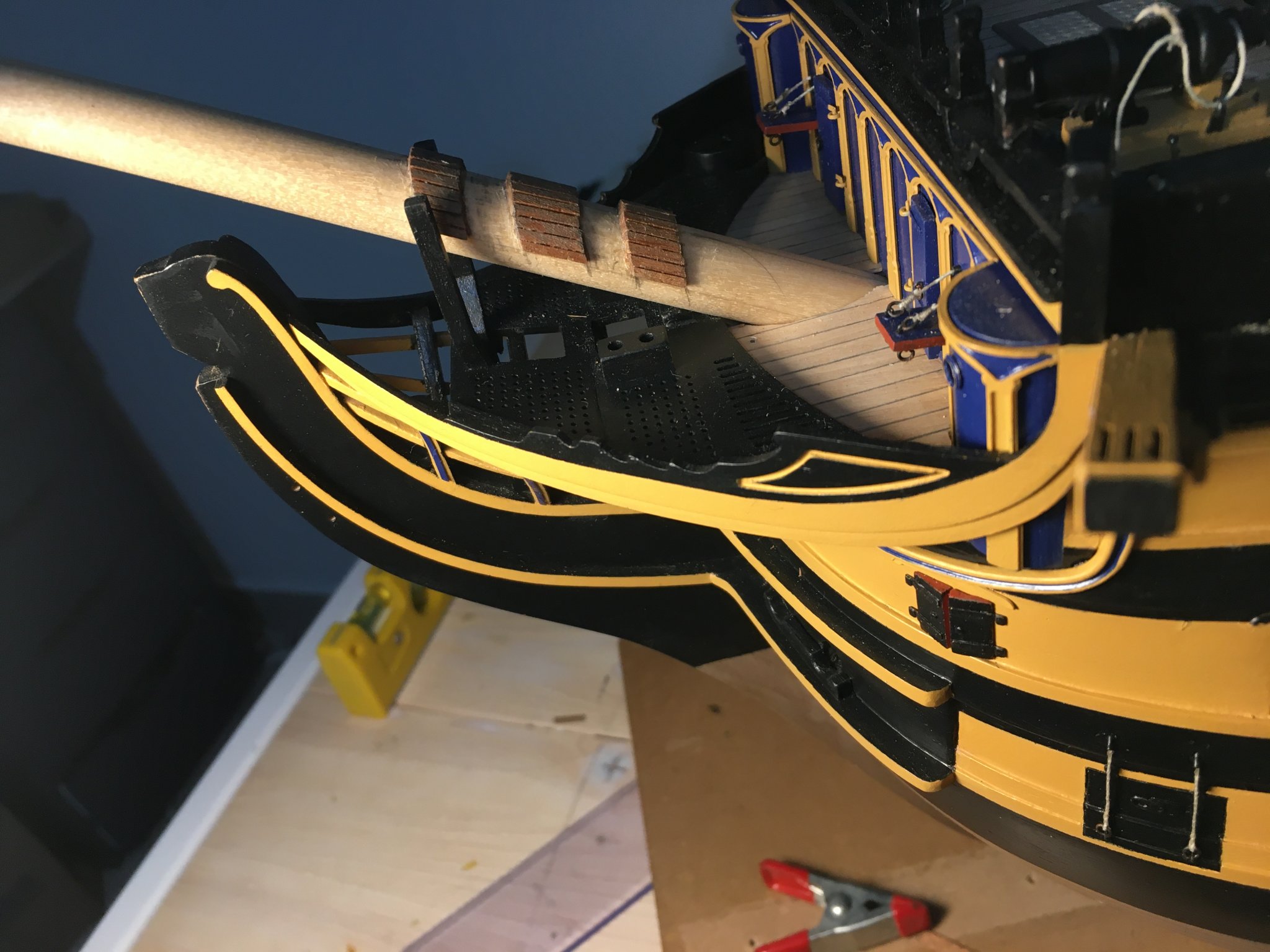
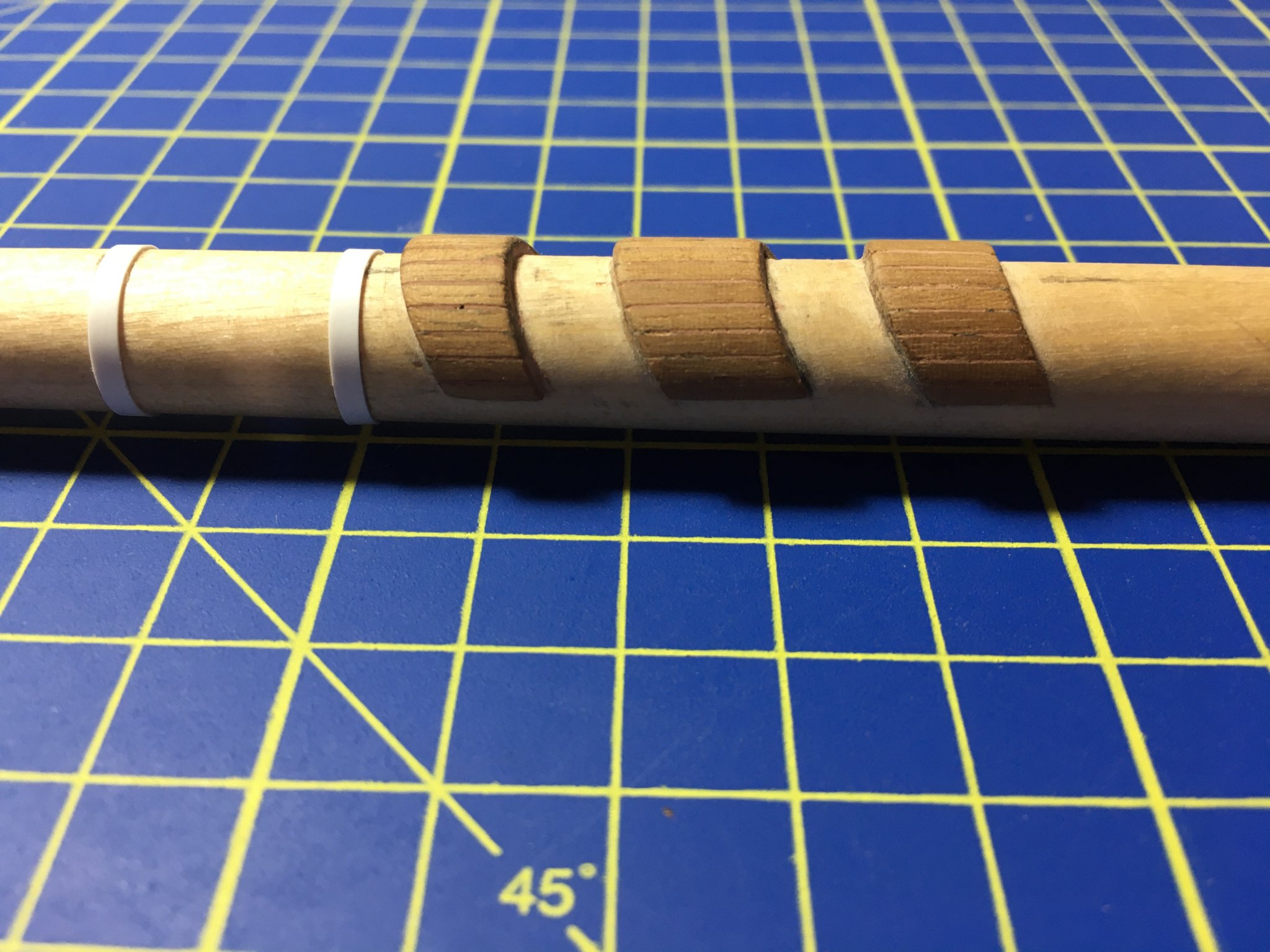
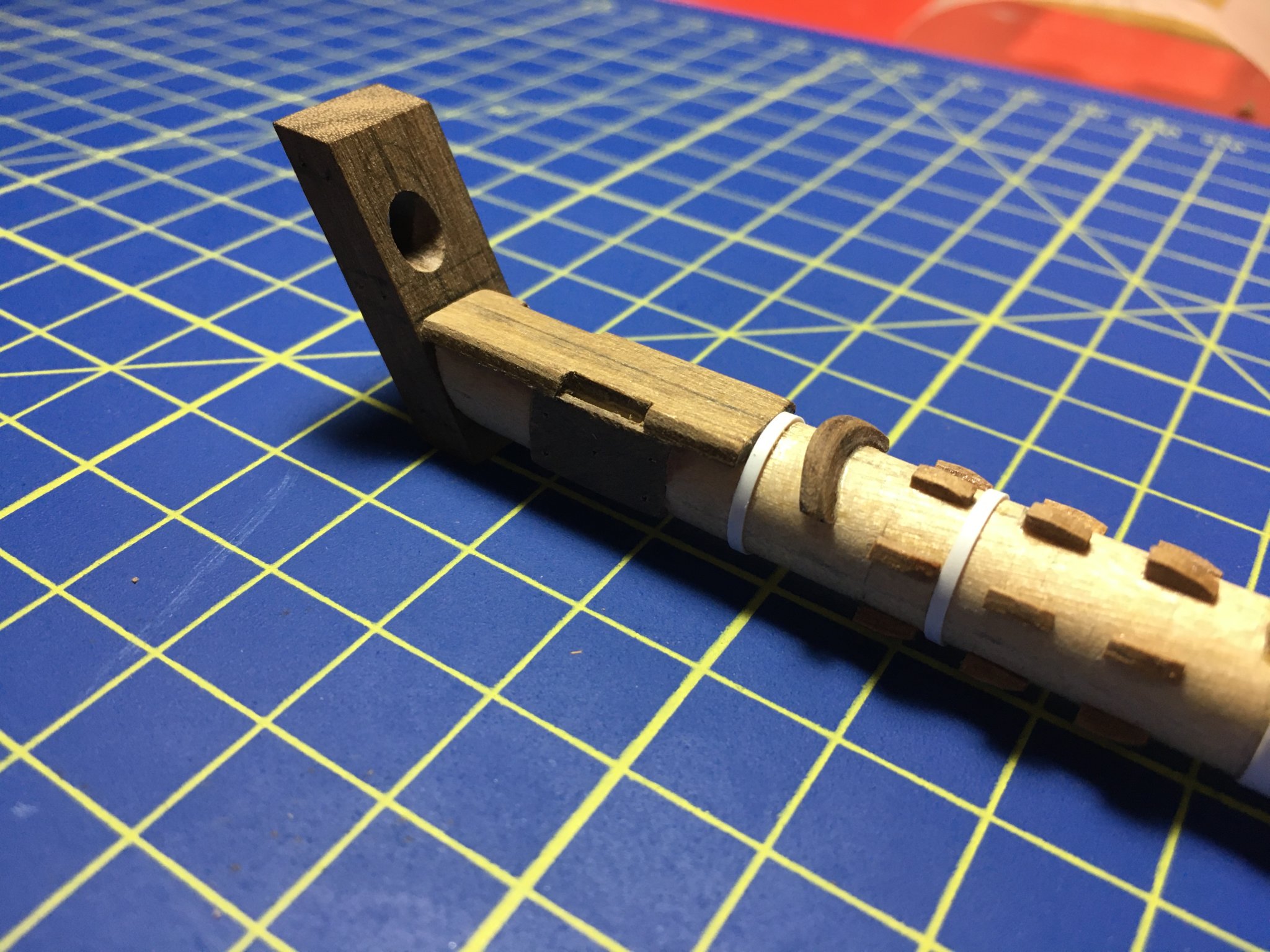
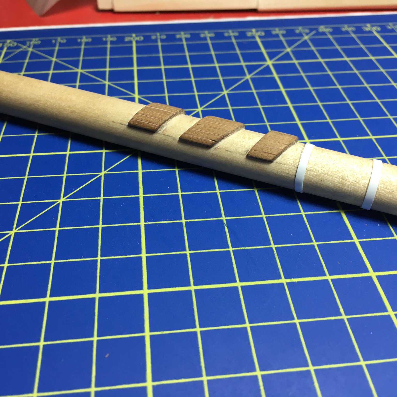
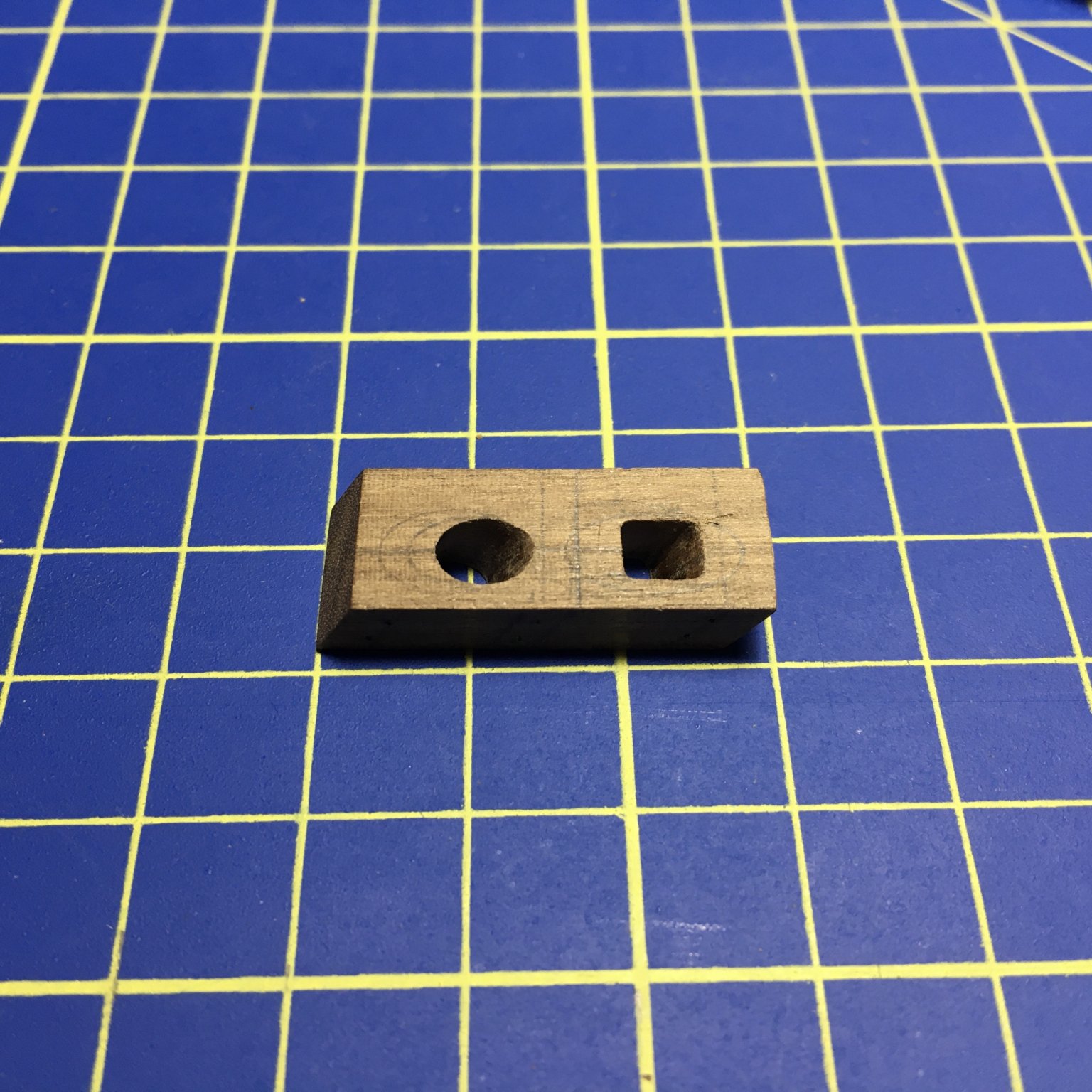
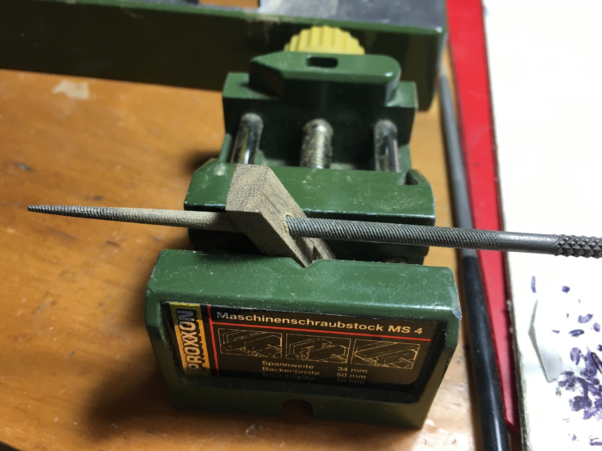
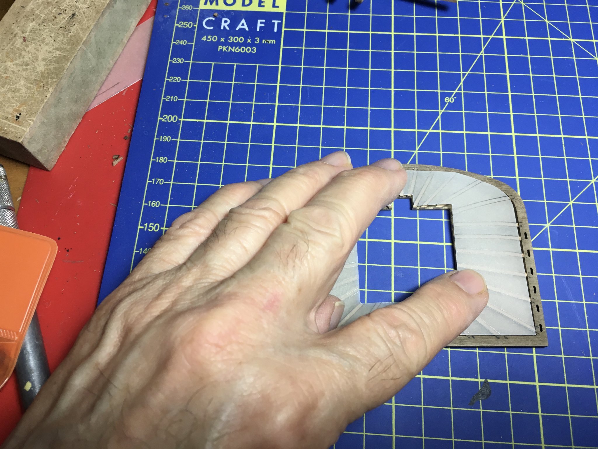
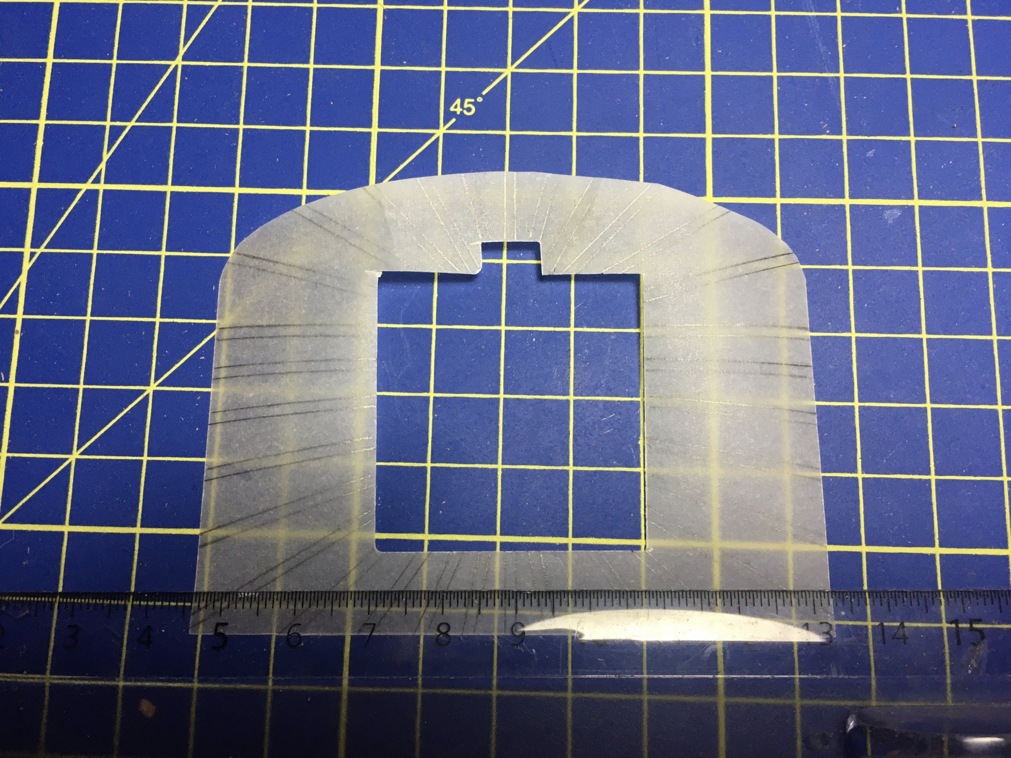
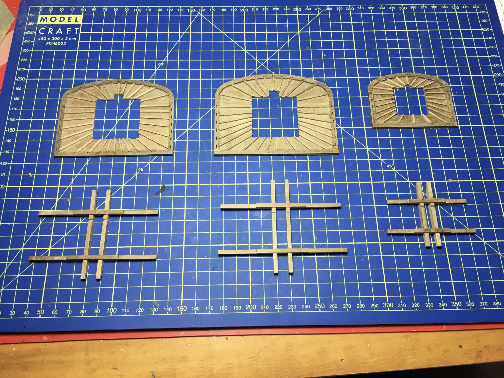
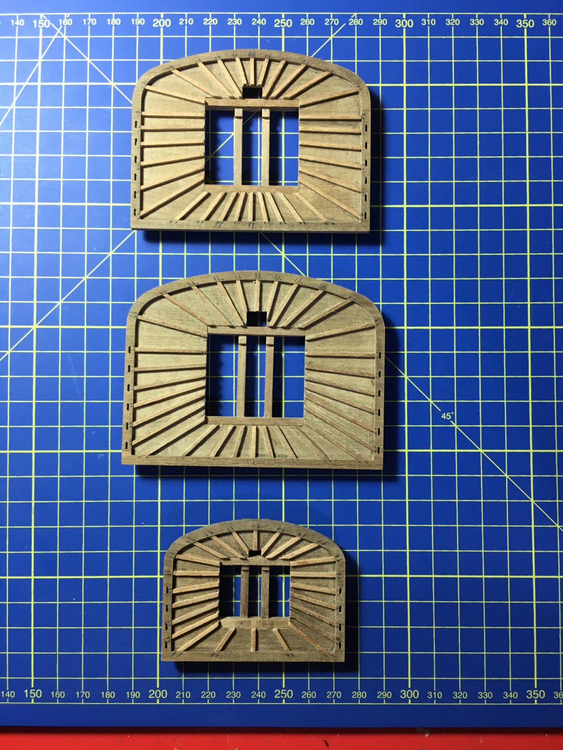
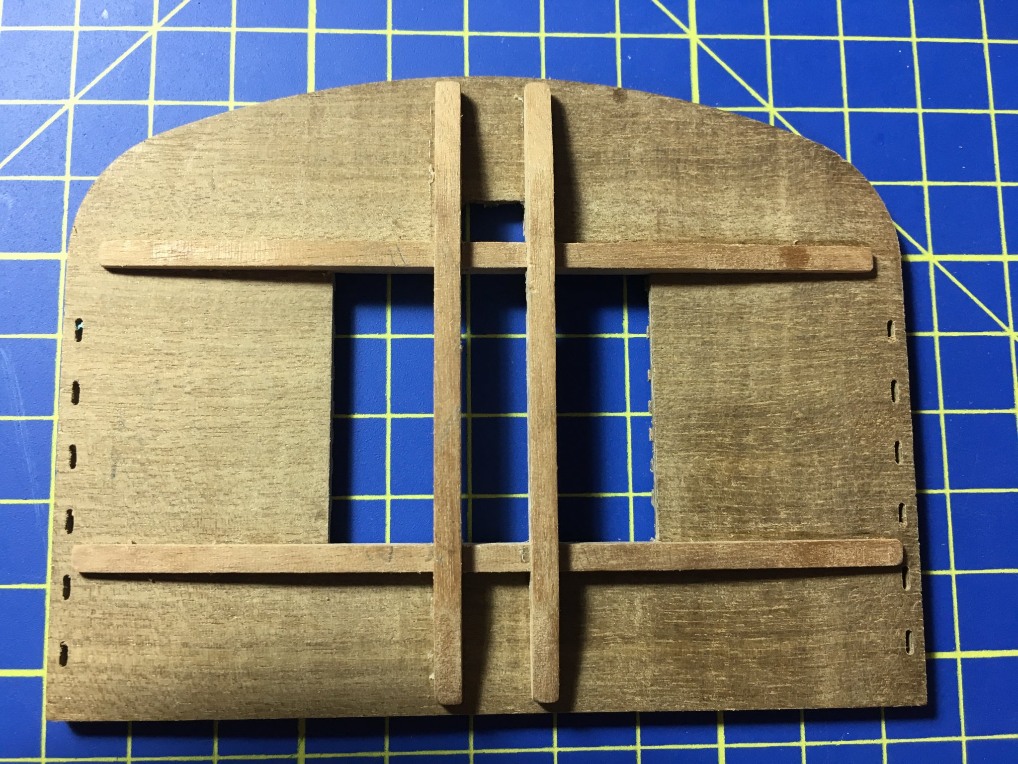
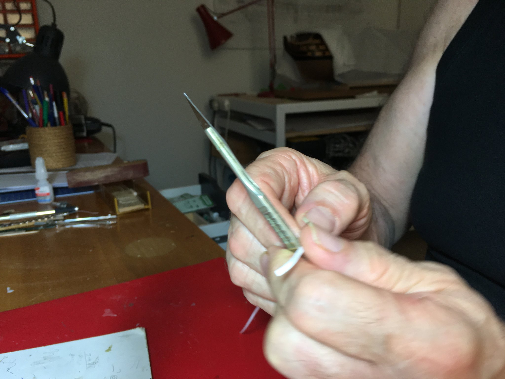
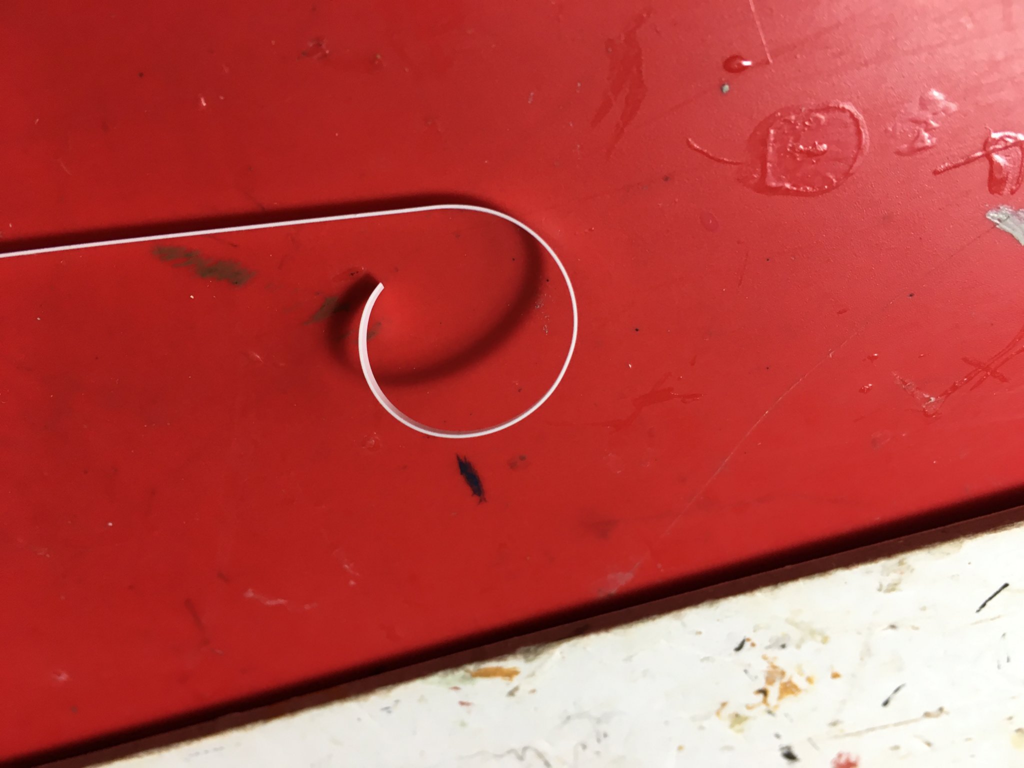
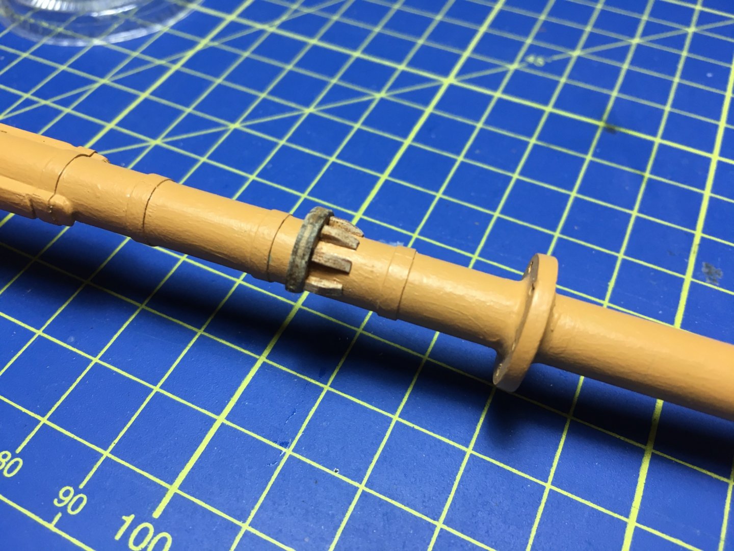
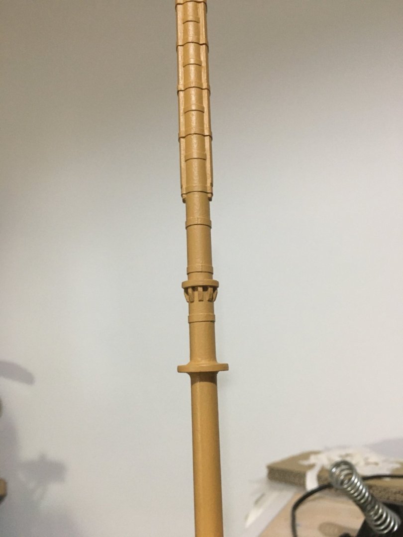
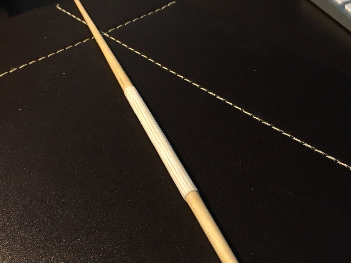
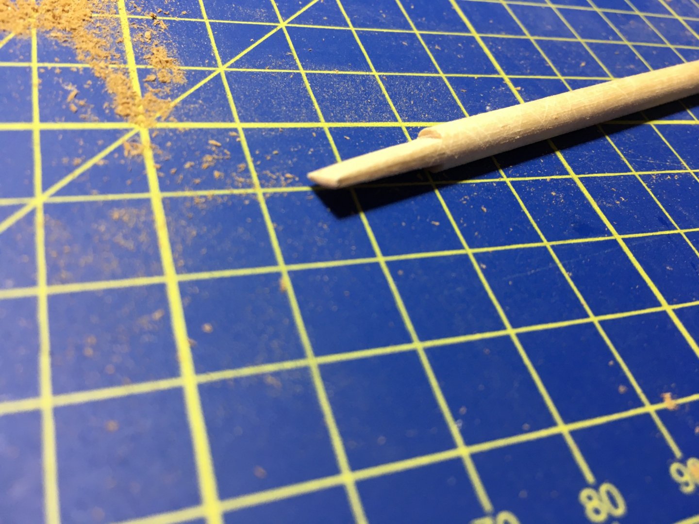
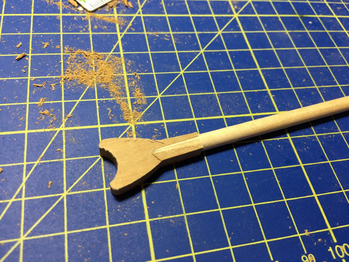
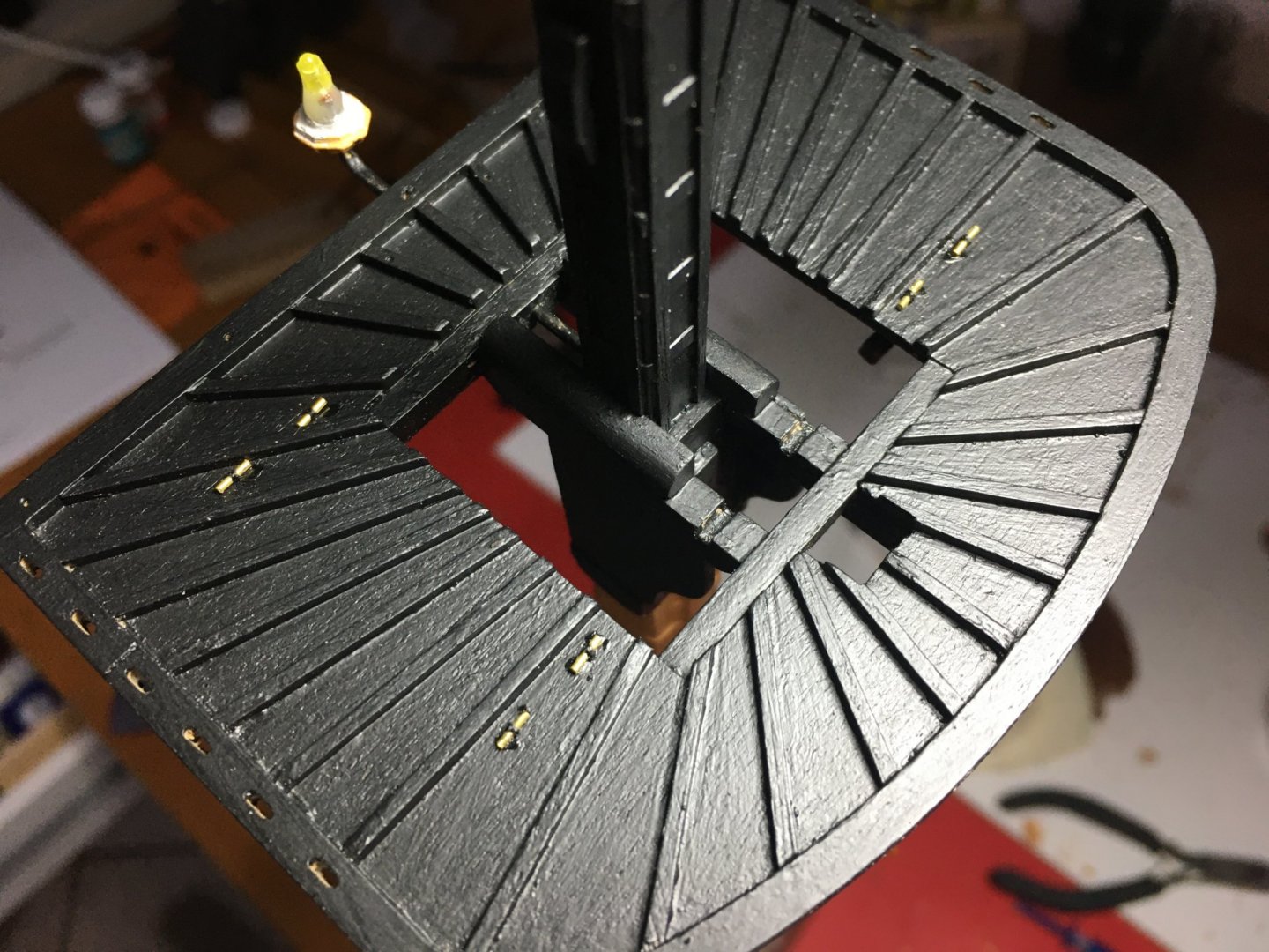
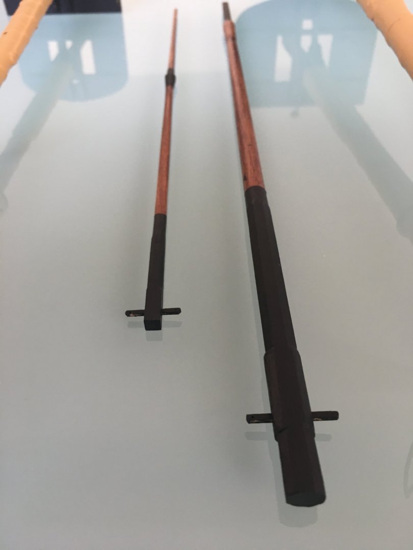
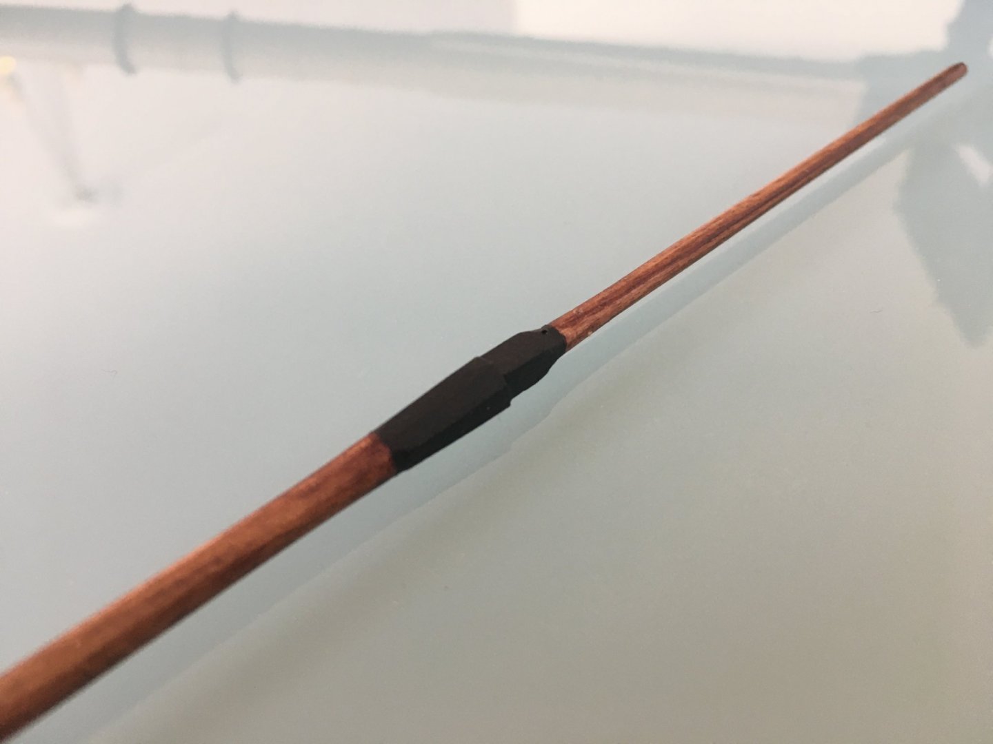
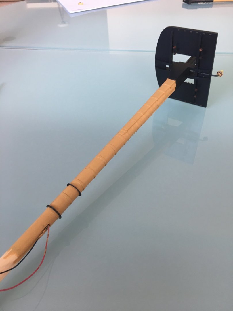
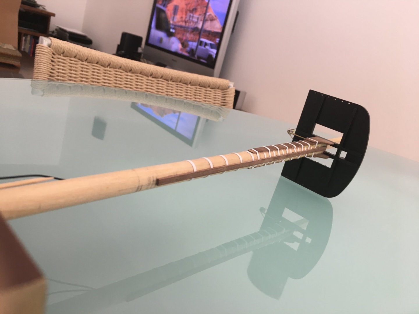
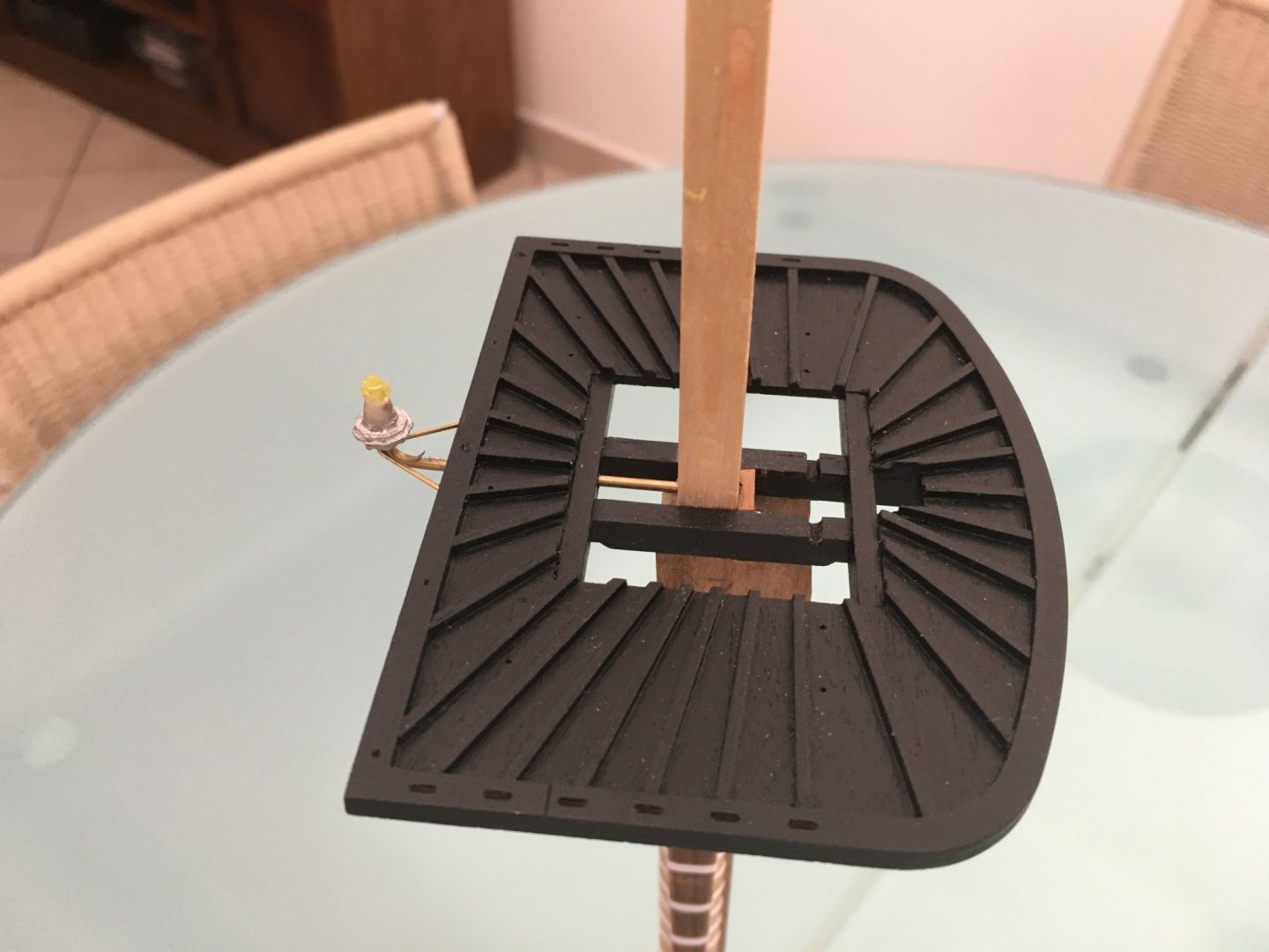
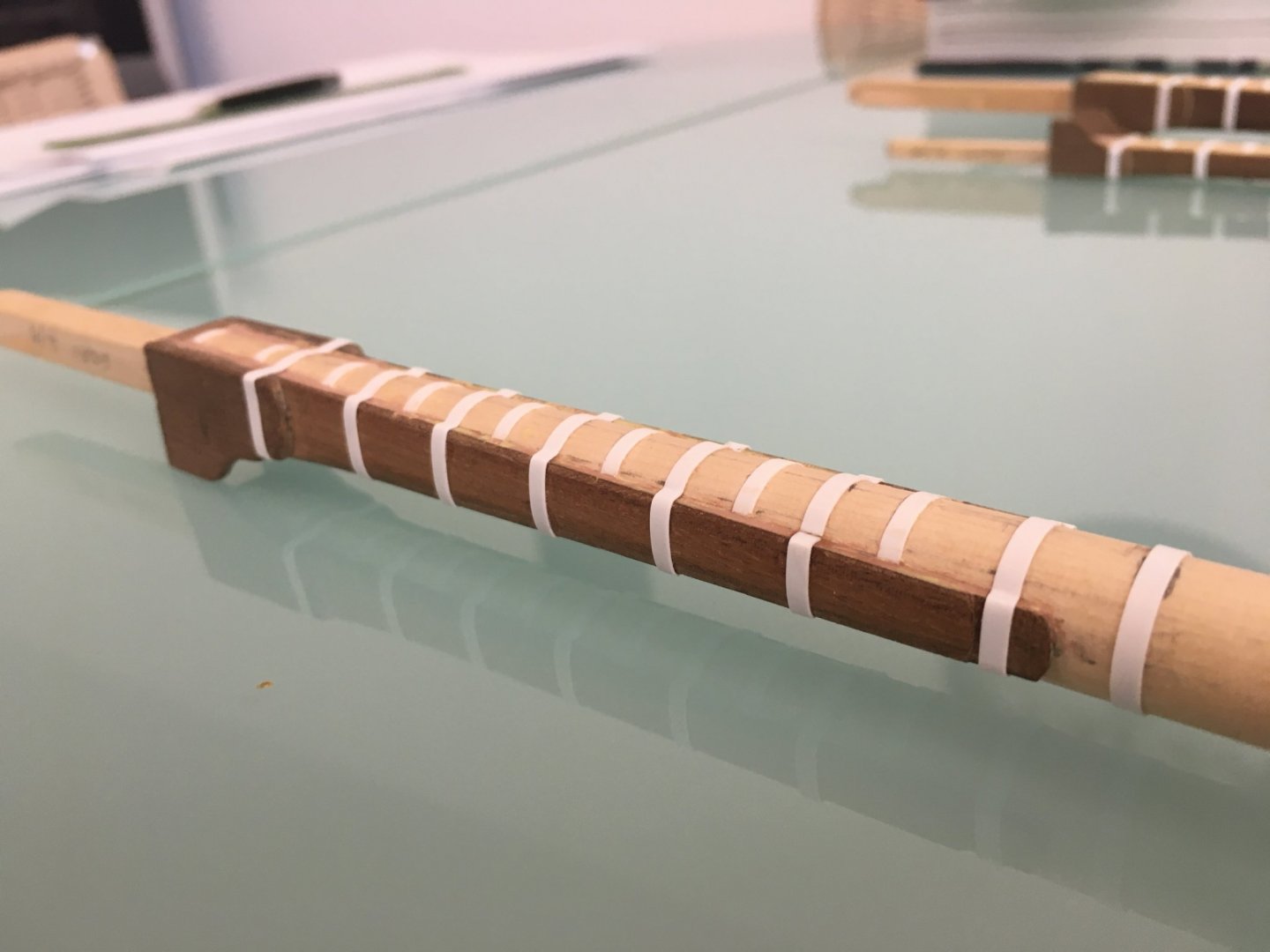
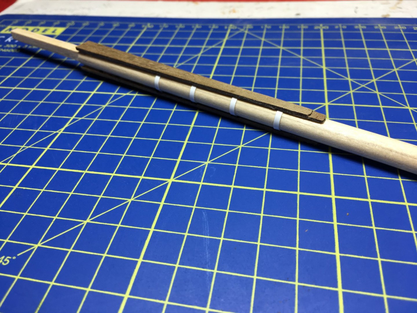
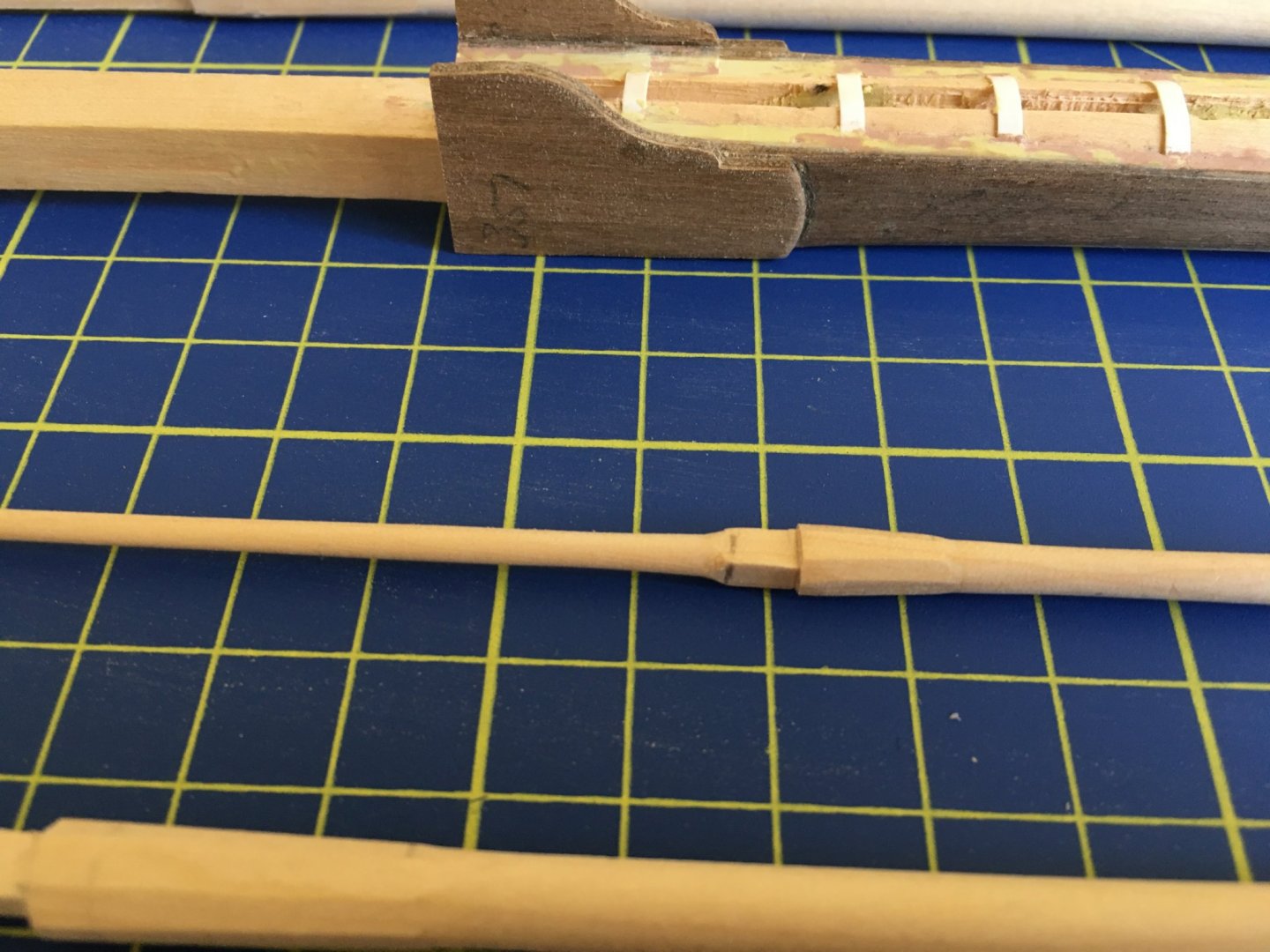
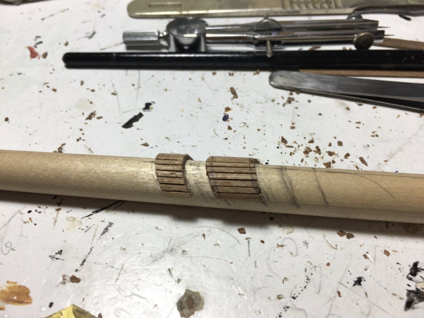
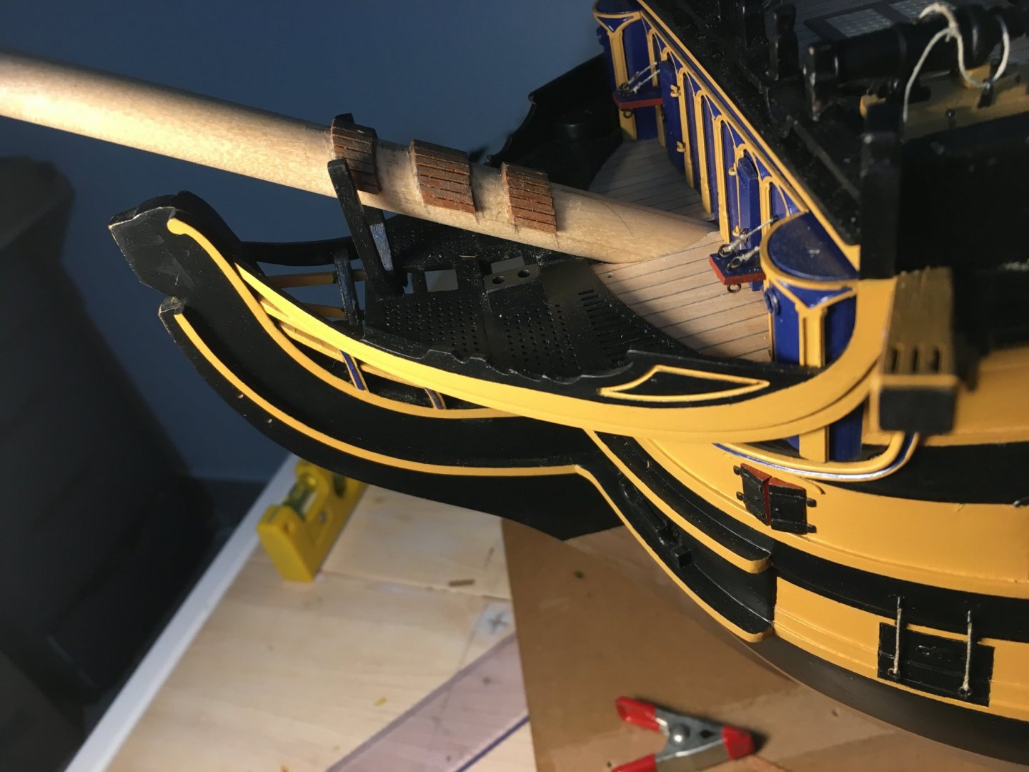
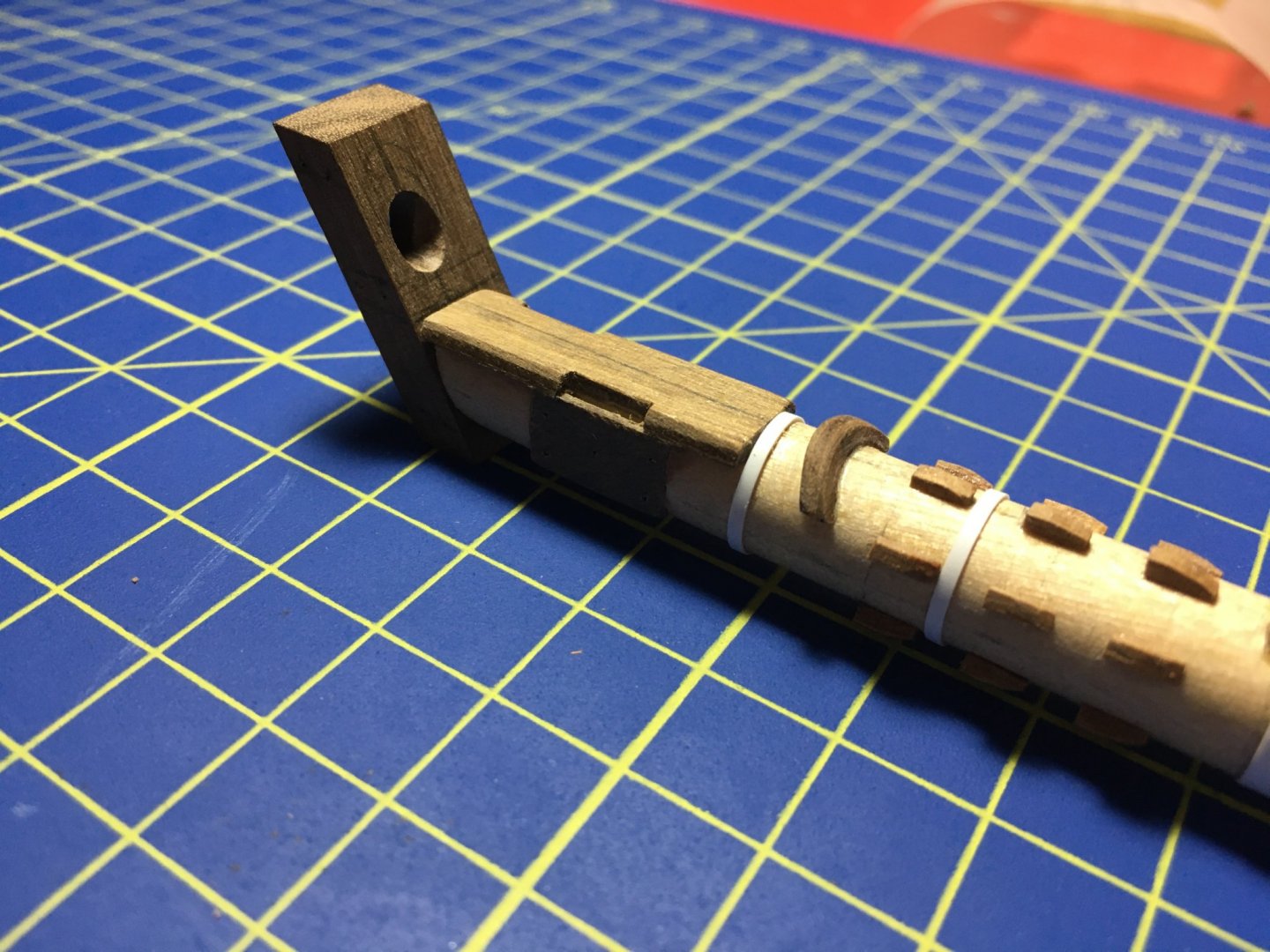
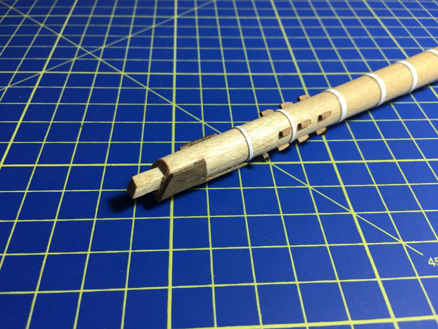
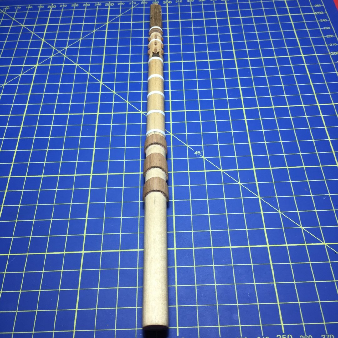
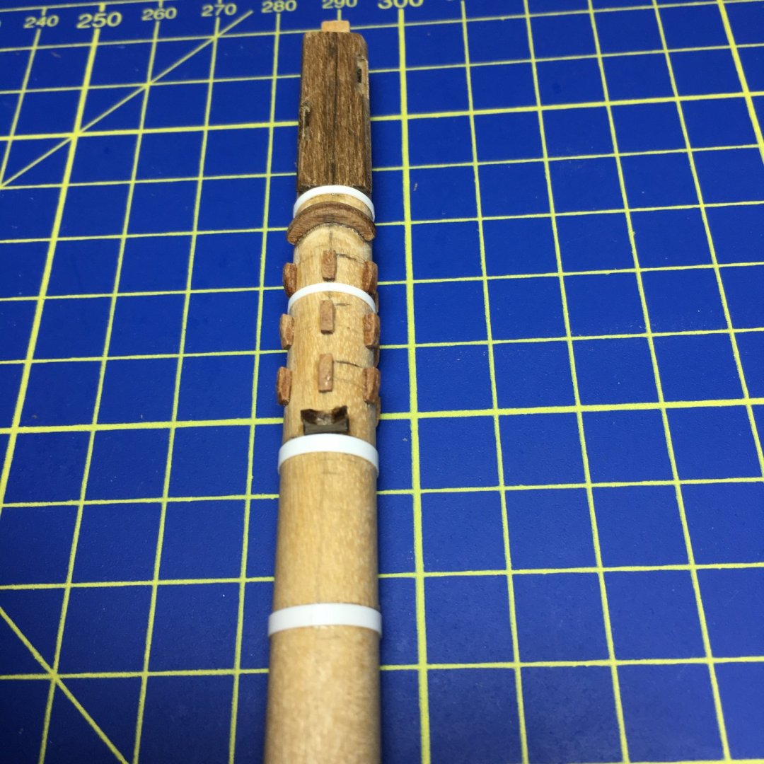
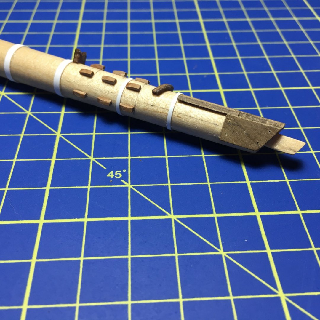
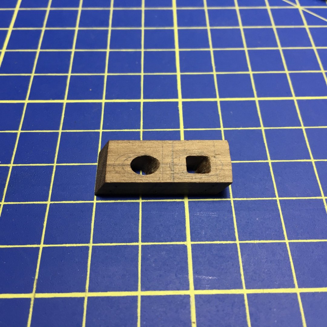
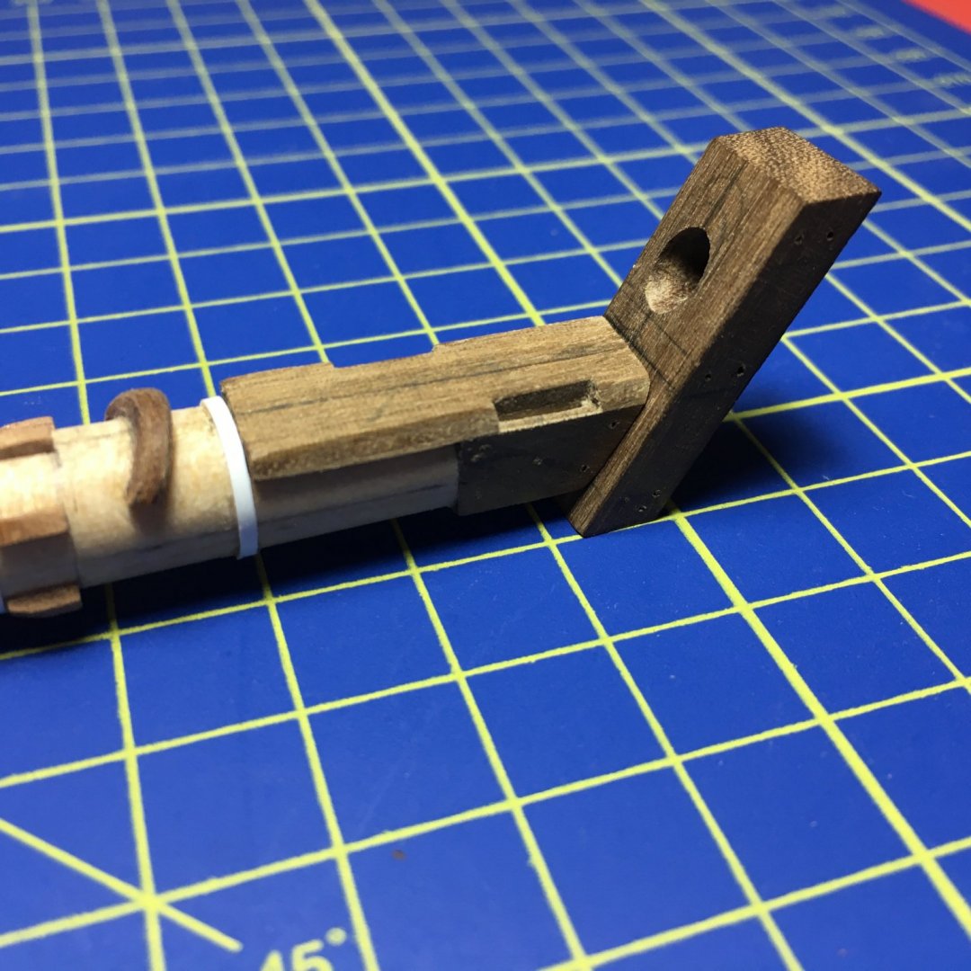
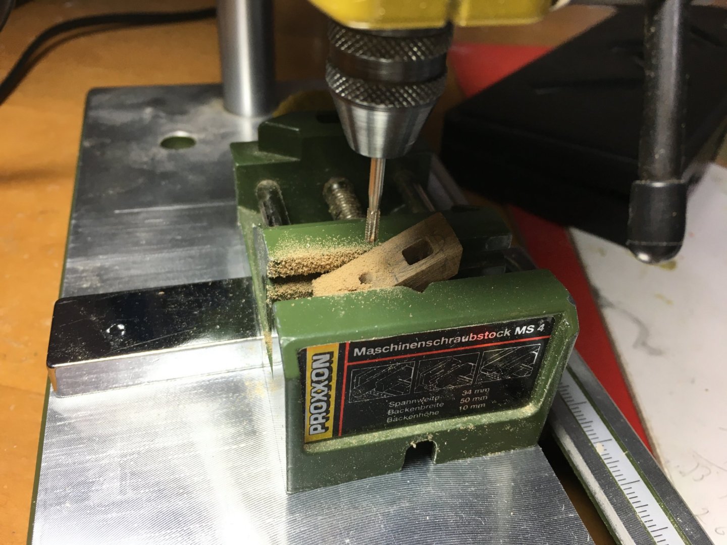
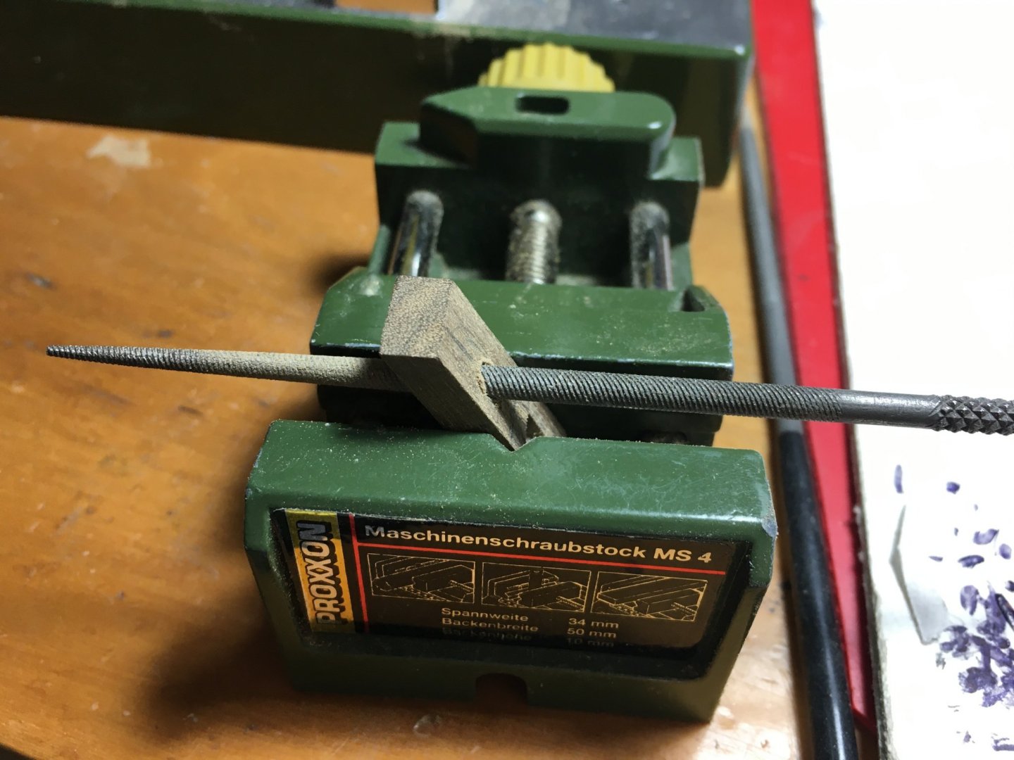
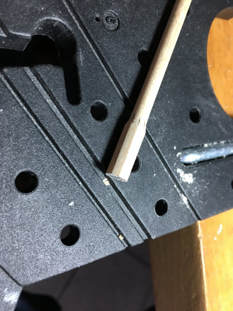
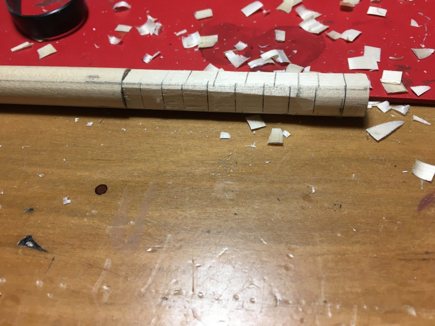
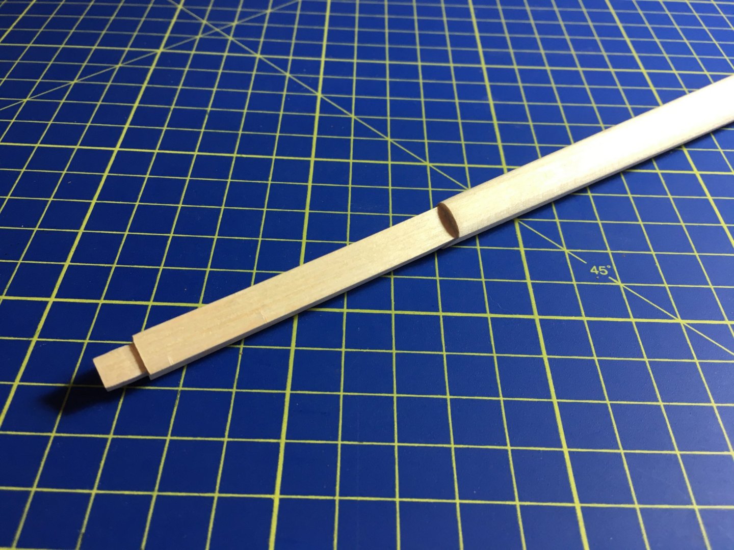
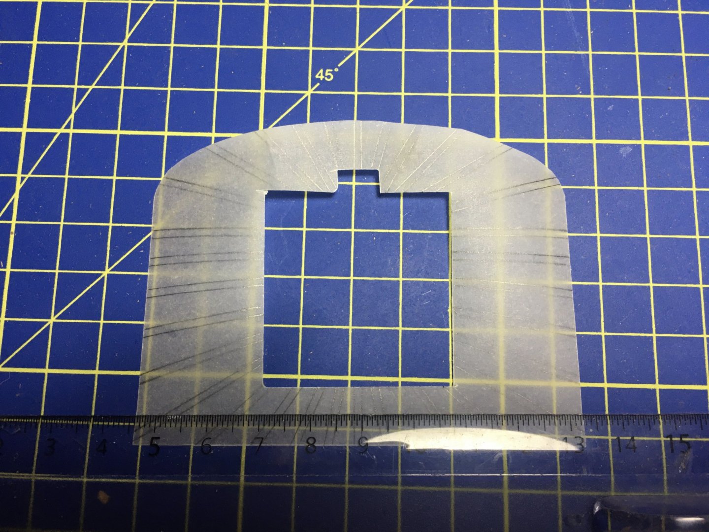
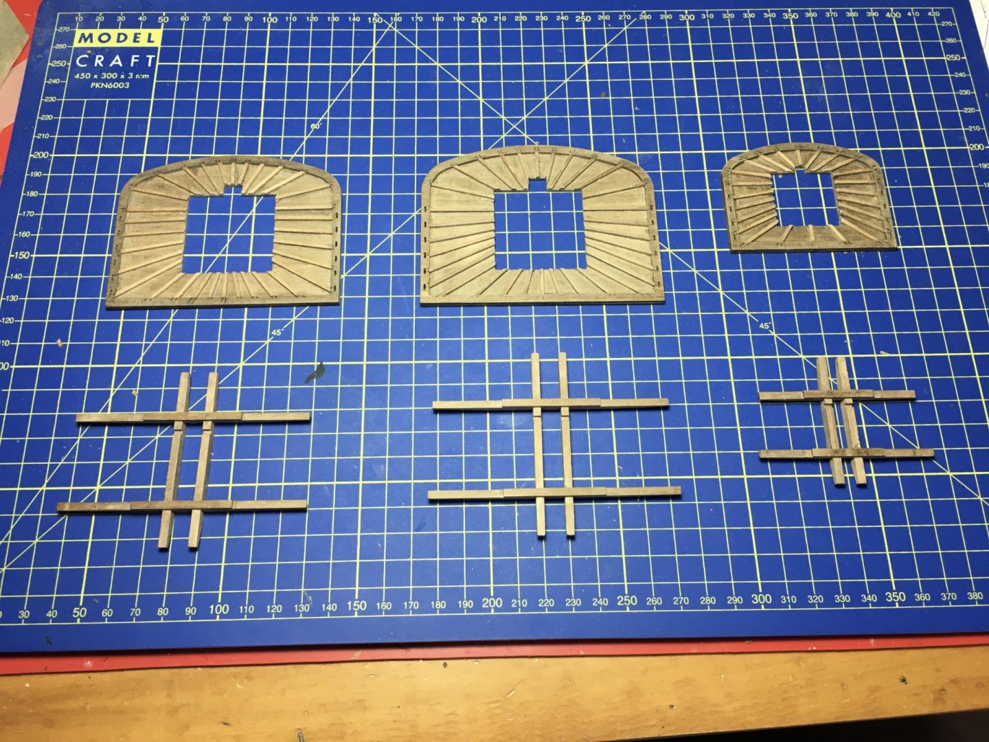
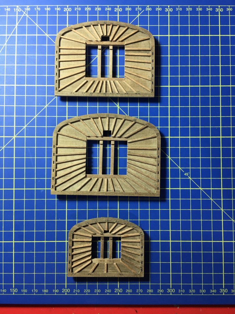
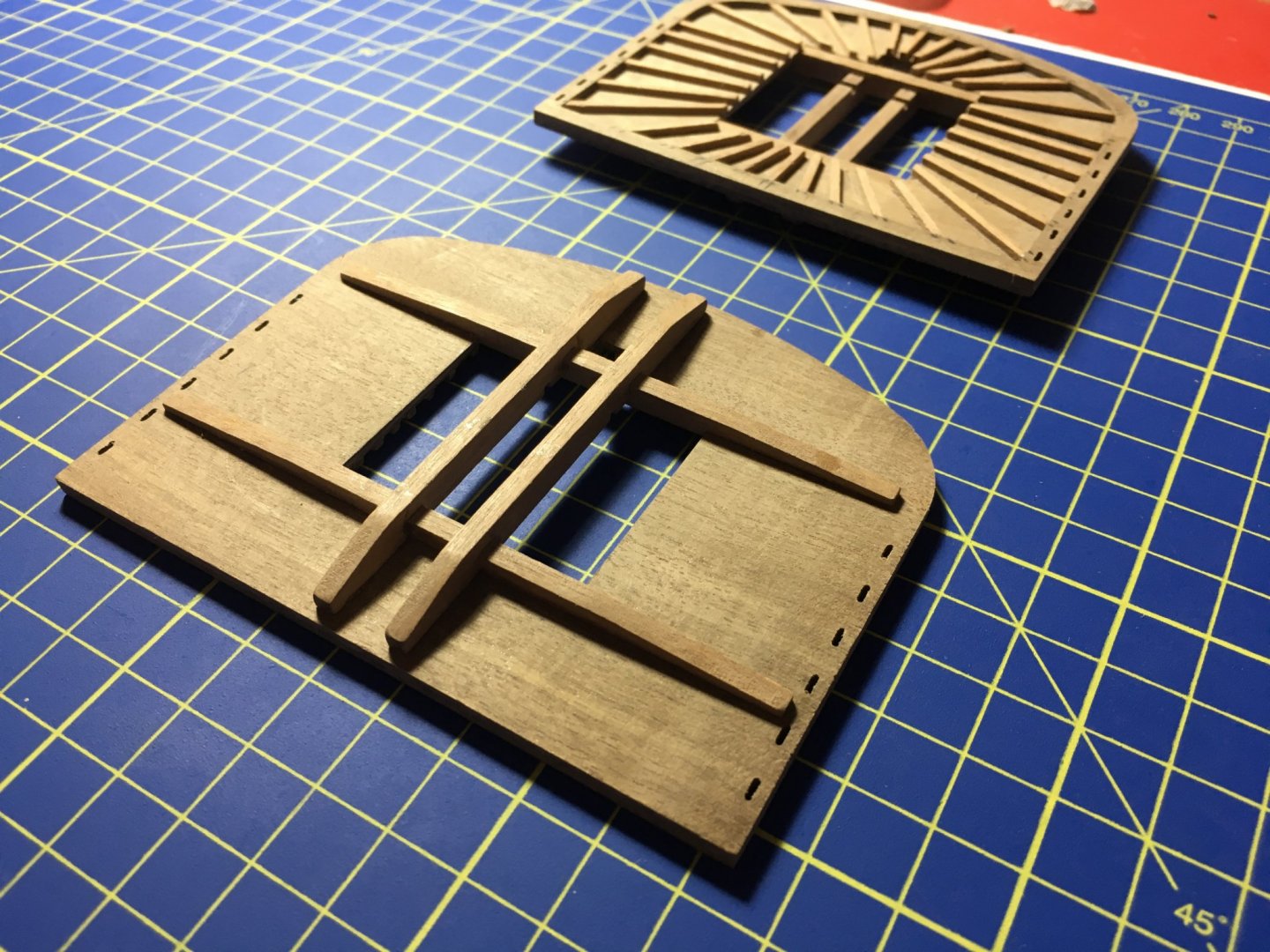
Thank you Michael. and thank you all for the likes. Still waiting for the brass treatment so I can carry on with the stern and galleries. Yesterday I received the good news that it has been posted and should arrive pretty soon. In the meantime I thought I might as well start some work on the bowsprit and masts. BOWSPRIT I started by first squaring the front part of the bowsprit on which the cap is fitted. It is cut an an angle as the cap, when fitted has to be perpendicular to the keel. Then I tapered it as indicated on the plans. Positioning of sheaves filed flat. Bowsprit bee flat glued in place. I made the gammoning saddles with 1.5 x 1.5mm walnut as indicated in the manual. I noticed that some builders did them by using a piece from the same dowel and hollowing the inside. The idea is good but since saddles have to go down to half of the mast diameter, to achieve that you have to use a larger diameter dowel, otherwise it is going to stop short. I had a try with the 1.5 x 1.5mm strips on an extra piece of dowel first and I was satisfied with the result. One important thing is the positioning of the saddles on the bowsprit. If you mark them exactly as indicated on the plans you might end up with their positioning out of line from where they should be. The best thing is to insert the bowsprit in place, making sure it is all in and from there mark the saddles. The space between the saddles has to be exactly in line with the two slots on the stem from where later on, a line has to pass through, up and round the bowsprit from in between the saddles for nine times. Also keep in mind that the saddles should be vertical when the bowsprit is positioned on the model. Strips are cut just a bit longer and trimmed in place with inexact knife when glue is thoroughly dry. Gaps filled with a filler and strips sanded round. Still need a bit more of filling and sanding. I made the bands out of styrene strips 0.25mm x 2mm When making the bands out of styrene grab the strip between your finger and something with an edge like the handle of a knife as shown in the picture and give it a pull. The styrene strip will curl round and keep the position. If the curve is still too big, give it another pull and it will curve even more. This is very handy so that it keeps in place when gluing round the mast. Top and bottom of the cap to be bevelled to be in line with the bowsprit when fitted. Holes in cap have also to be drilled at an angle to be in line with the bowsprit. Also take note that they are not in the middle of the cap but offset to the port side. The lower part of the jibboom is an octagon. The jibboom is made from a 6mm diameter dowel. It tapers from 5mm to 3.7mm. When I tapered it I left the part of the octagon still 6mm in diameter, then I shaped the octagon on the 6mm diameter. If you taper it to 5mm and then form the octagon, that part kind of looks thinner then the rest 5mm diameter dowel, and it doesn't look good. In my opinion it looks better this way and I think, correct me if I am wrong, it is the way it should be. Sheaves and jibboom support fitted in place. Stop cleats made from 1.5mm 1.5mm walnut fitted as well. FORE LOWER MAST Also started some work on the Fore Lower Mast.The top part of the Lower Mast has two squared sections, 8mm square and 6mm square. On the top of the mast I marked 8mm square and another 6mm square inside it. then drew lines from the four points of the square down along the dowel to a length of 73.1mm as a guide. With a fine saw I made several cuts, being careful not to go down further then the 8mm square and chiseled out most of the material, then I took out the rest of it on my proxxon table fitted on my proxxon drill stand with a trimmer bit. In a way used it sort of like a milling machine. Don't get me wrong, it does not in any way substitute the actual Milling Machine, I do not own a milling Machine, but I have seen some work, and it is in no way any near to it. I mostly use the table to make some accurate holes and similar things. IT IS NOT A MILLING MACHINE. The real milling machine is a beautiful machine, but quite expensive, and in my opinion it's cost does not justify the little need I have for it. The 8mm square sanded and finished. the 6mm square formed as well. TOPS To be honest I thought the tops were going to be more difficult to make then they actually were. First I glued the gunwale to the platform. To mark the battens I used a piece of tracing paper to trace the battens from on the plans. Then I transferred the end points of the battens on the platform. I glued the battens in place leaving the inside a bit longer. When dry I trimmed them with an exacto knife and sanded them flash to the inside edge of the platform. All battens glued. Crosstrees and trestletrees assembled as well. Crosstree and trestletree assemblies glued to platform. That is all for today. Robert


- 527 replies
-
- 11
-
-
- caldercraft
- victory
- (and 1 more)
-
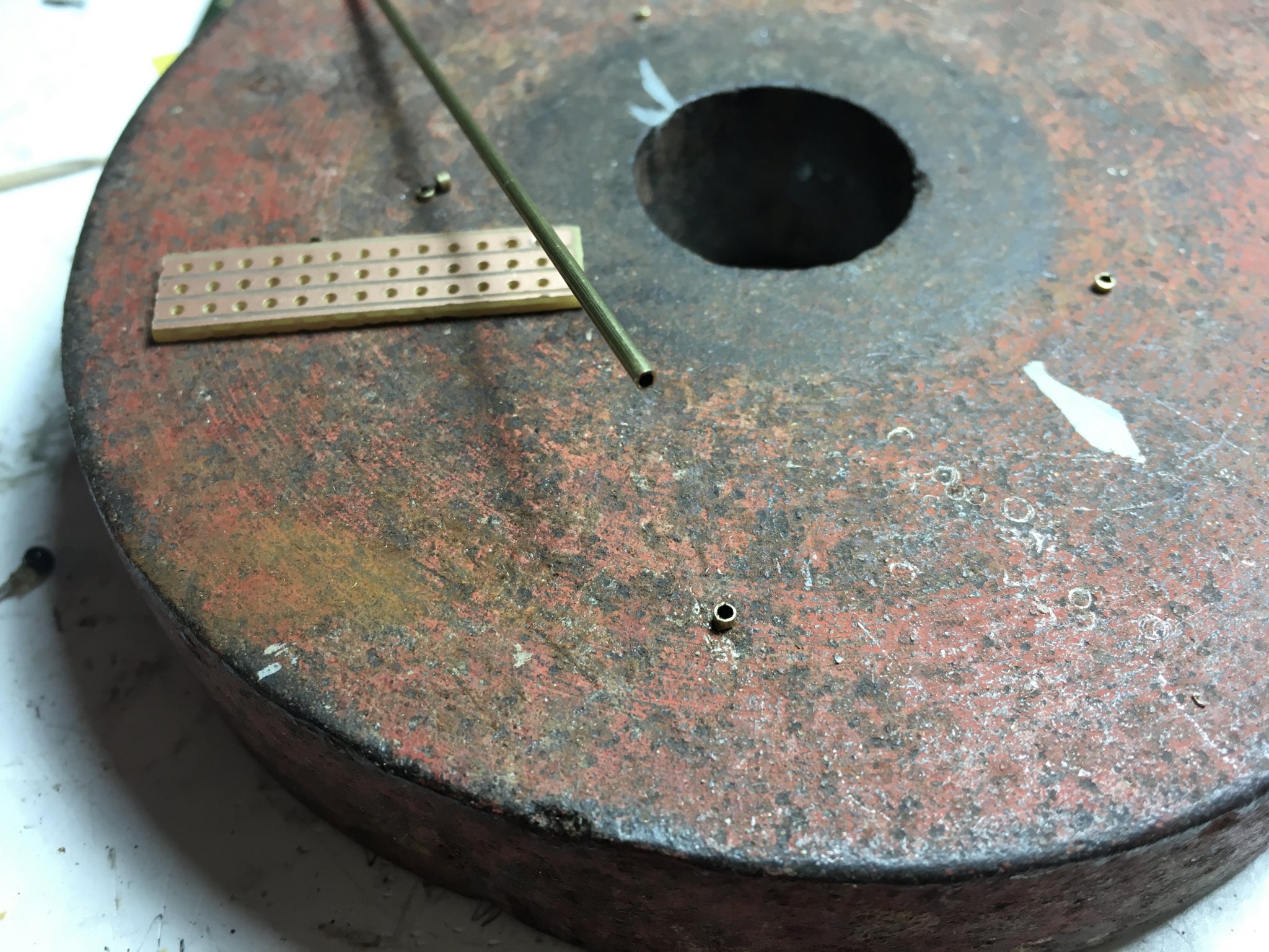
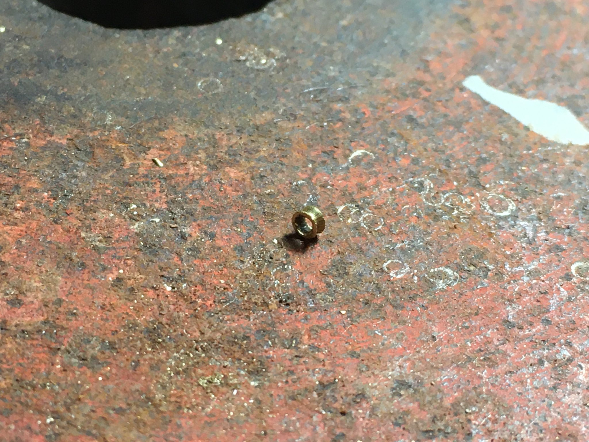
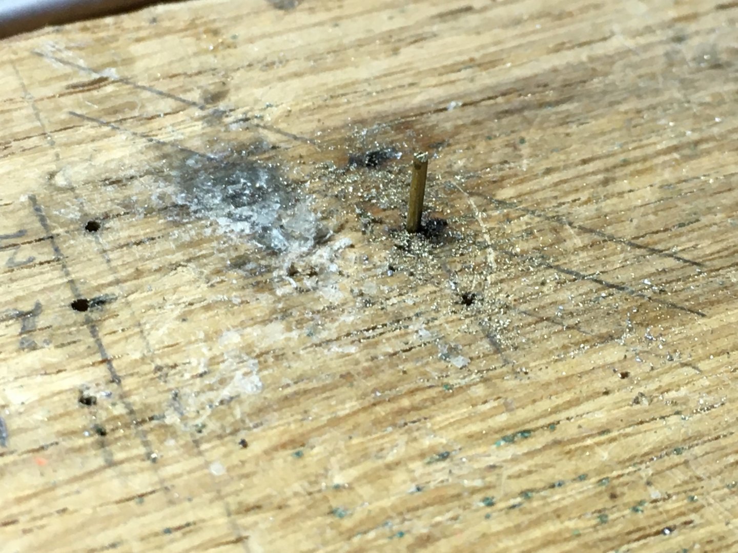
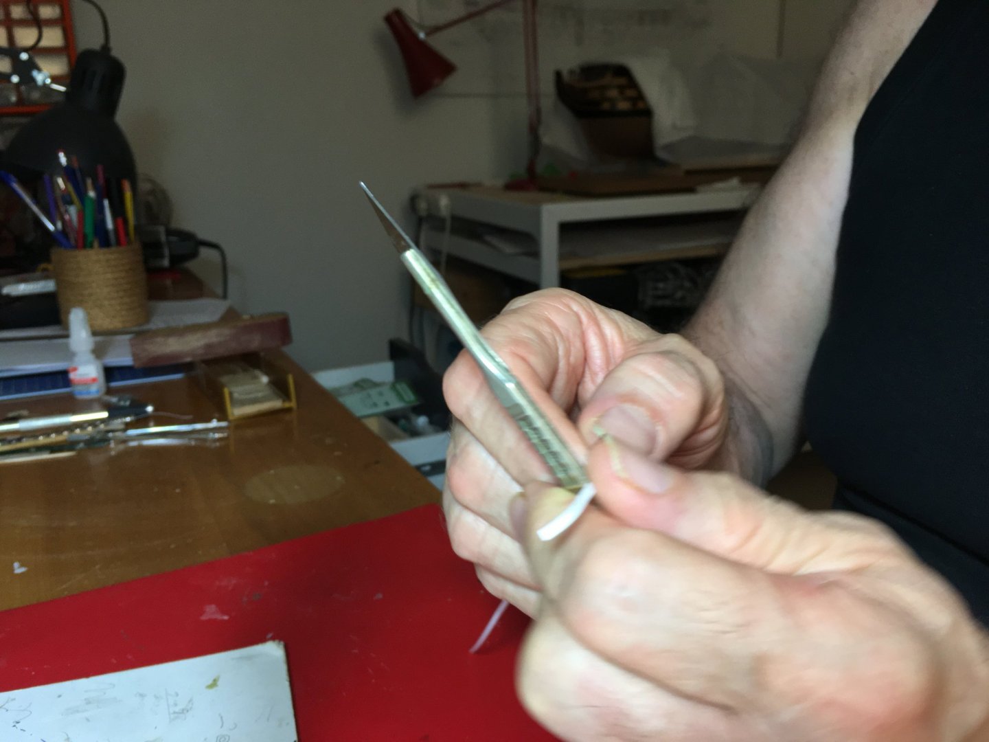
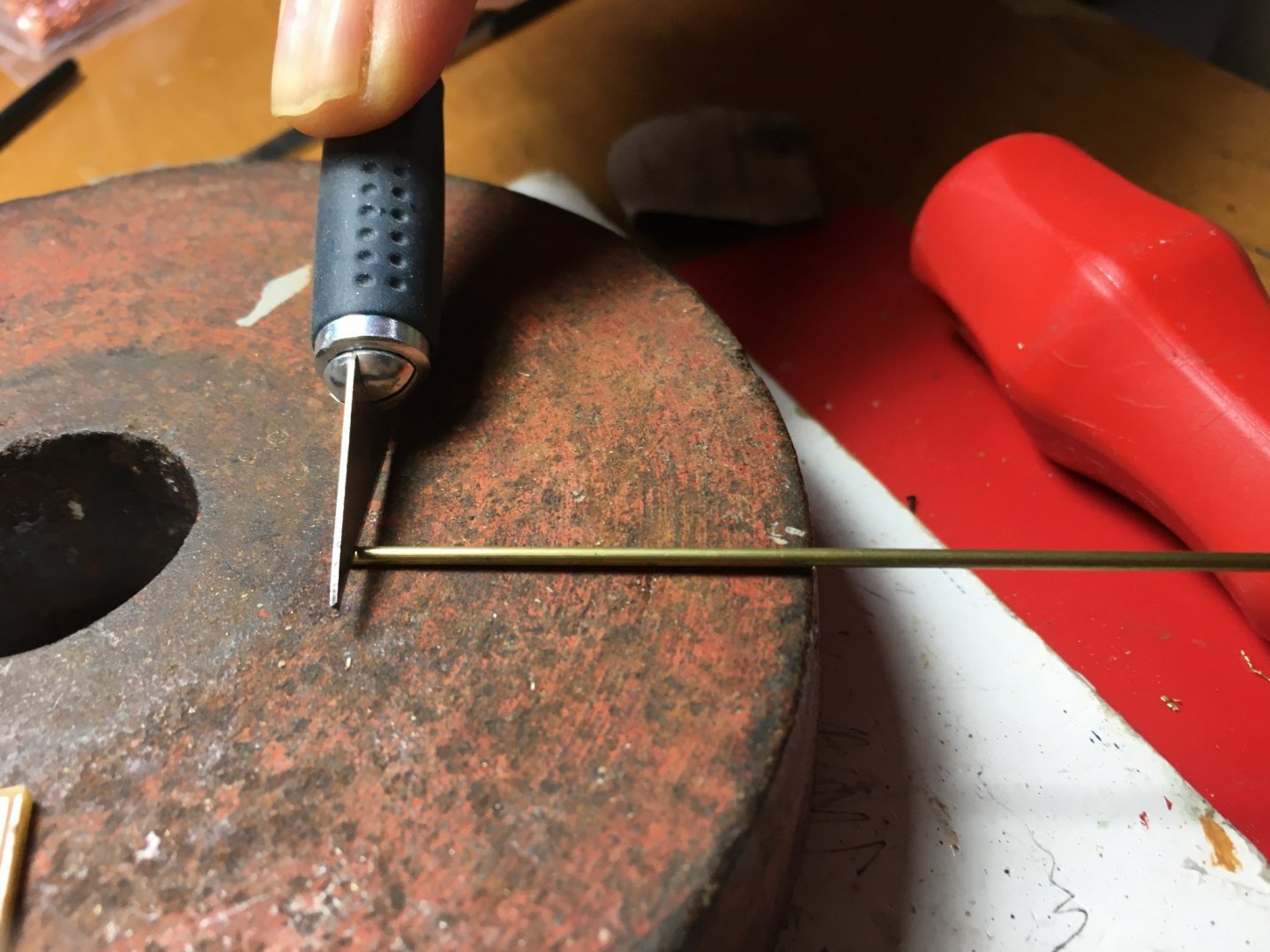
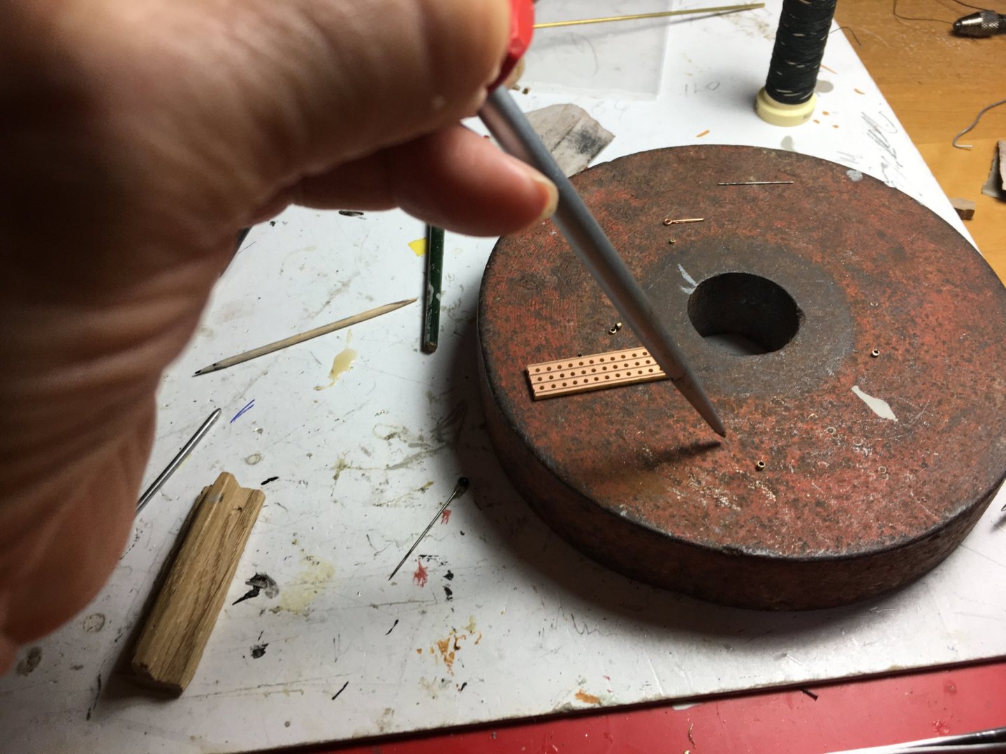
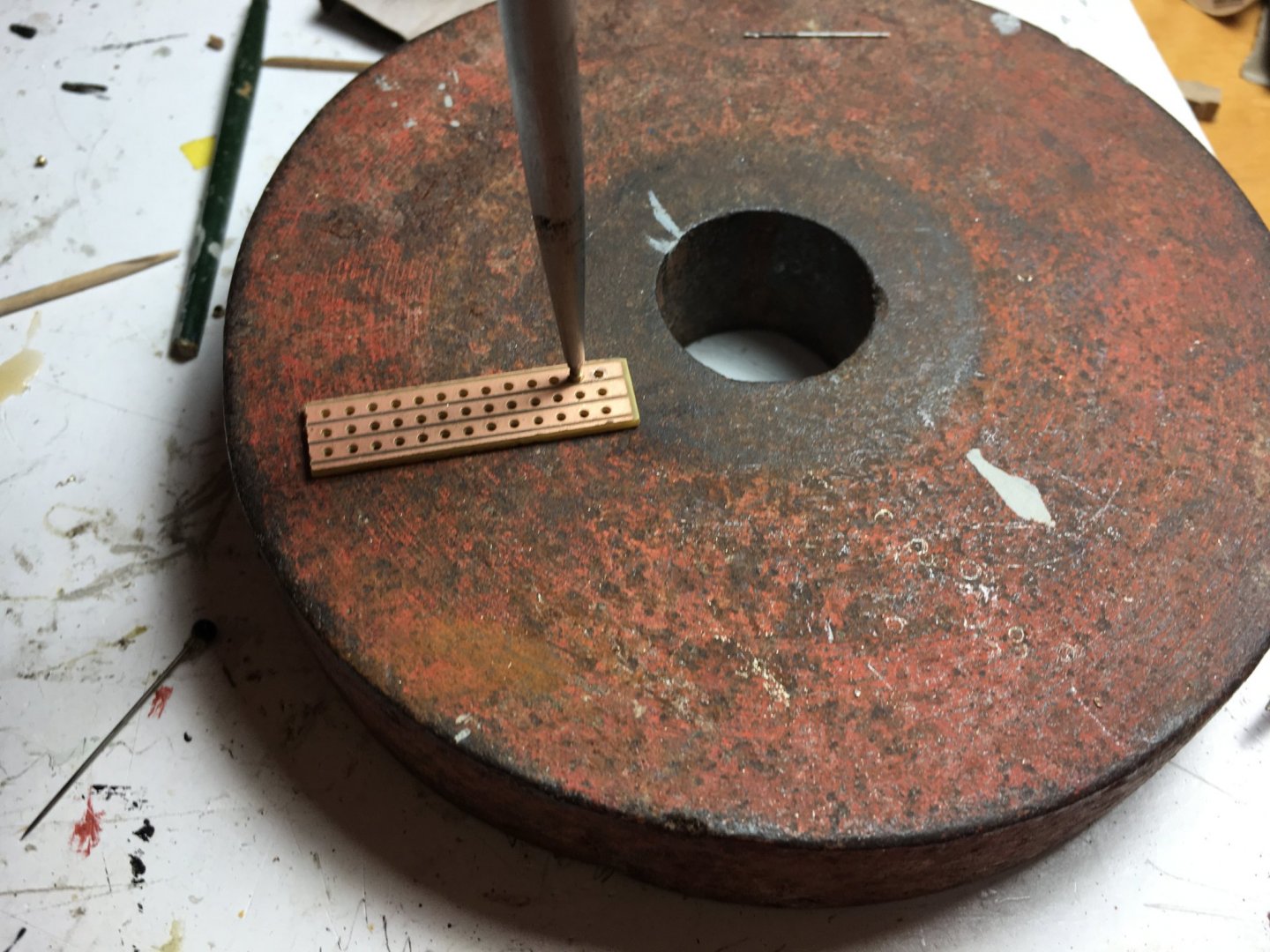
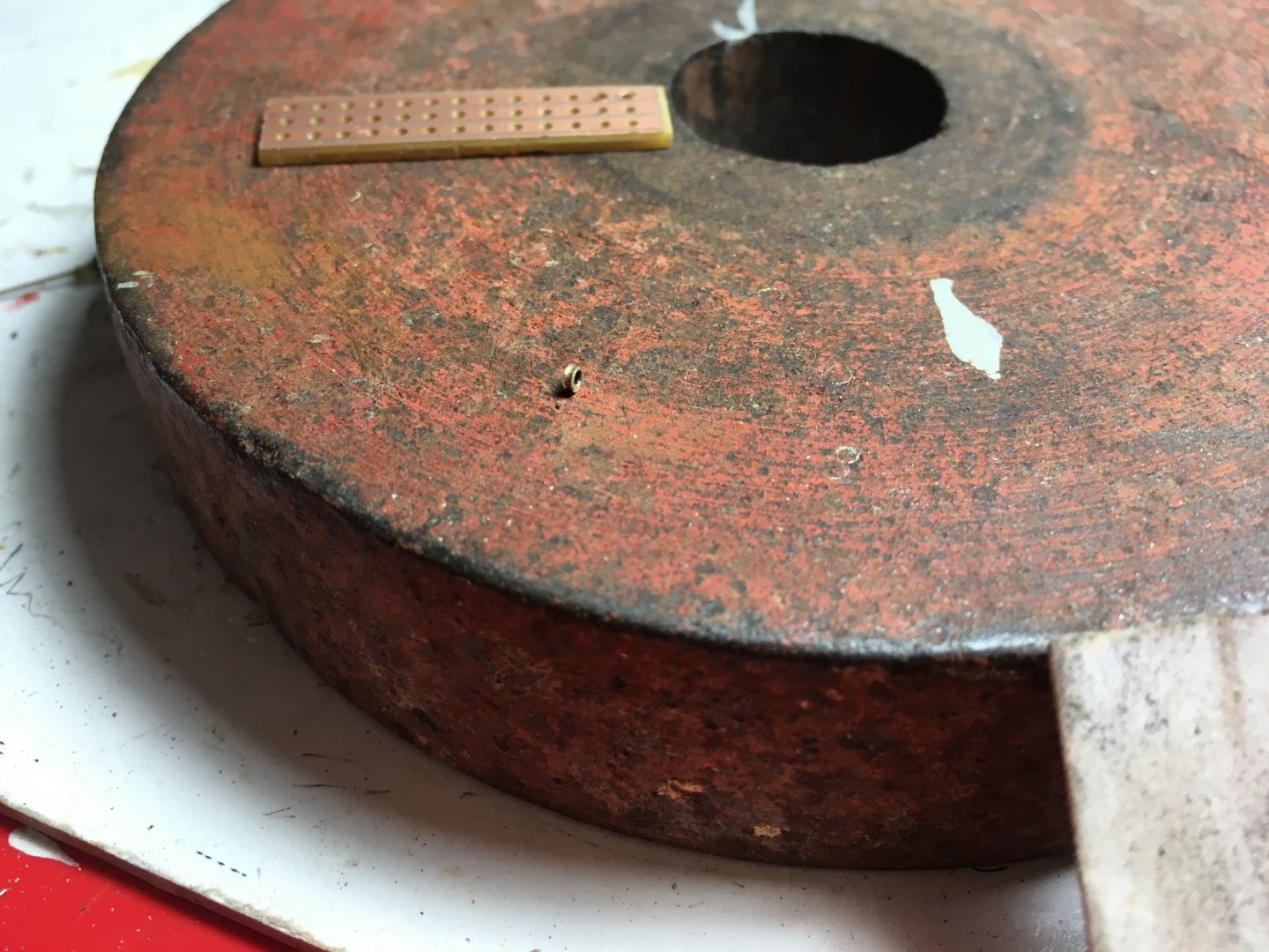
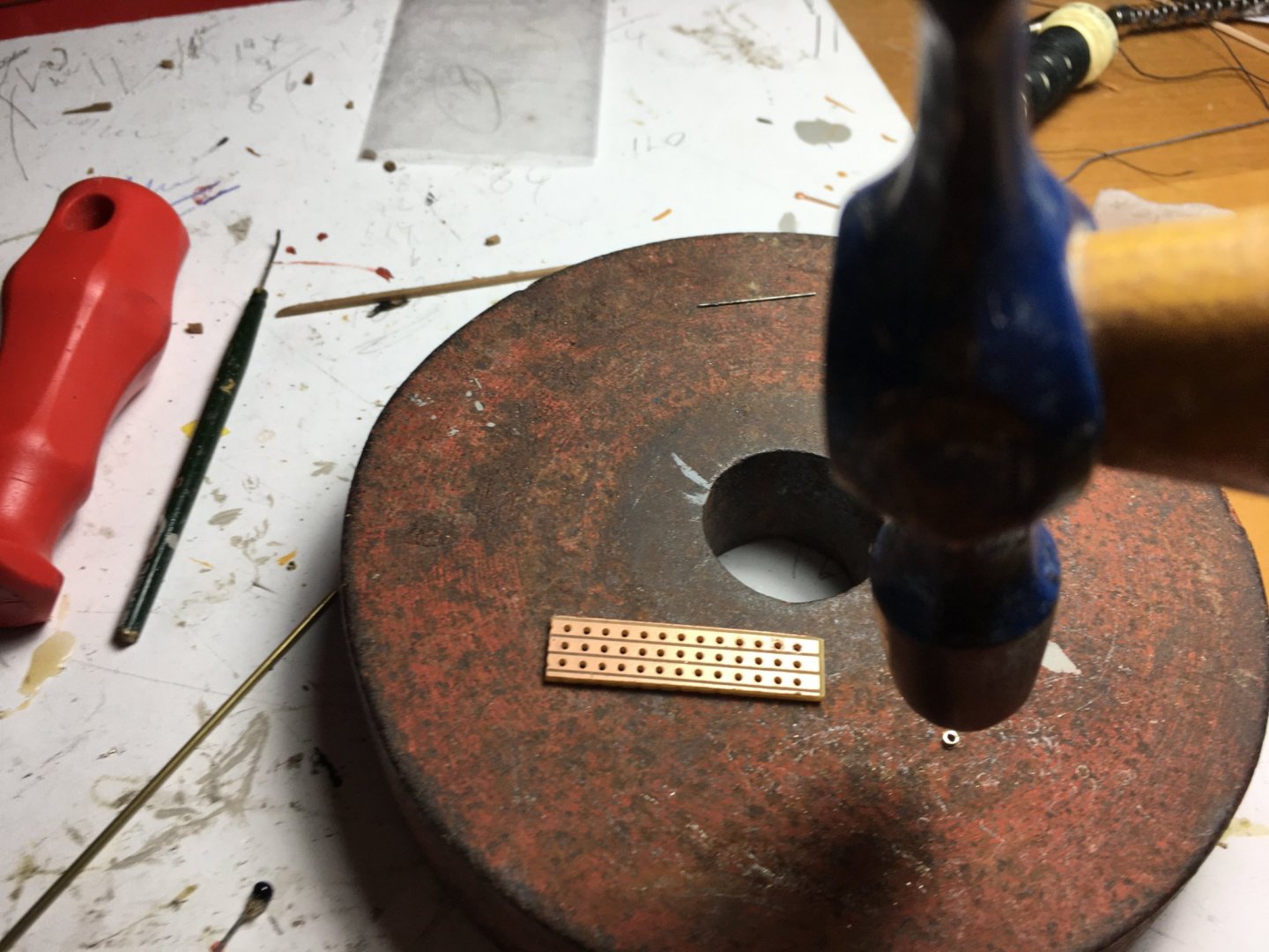
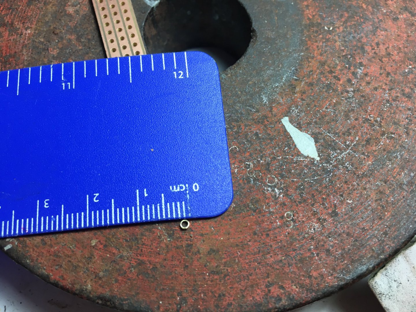
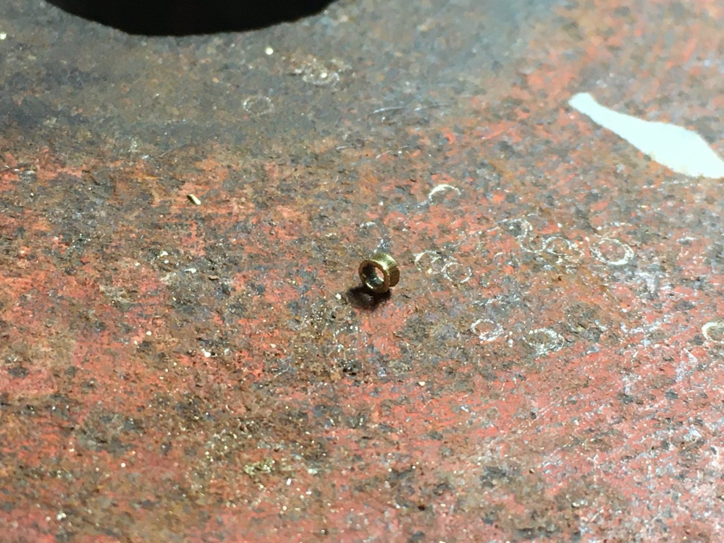
Thank you Heinze, your compliments are always appreciated coming from the builder of such an awesome Victory model. Thank you Jeff, looking forward to see how your planking is coming along. I don't have much to update, I am still waiting to receive the product I ordered online for the brass treatment before painting. I have to try it on the stern balusters before I continue on it. In the meantime I rigged the closed gunport lid in the bow and the two vents at the stern. Going through the rigging instructions I noticed that in various places were in realty you should have metal thimbles, eyelets were used. The thimbles have to be very small, so I experimented a bit to see if it's possible to replace the eyelets with the proper thimbles. Thought it's worth sharing, maybe someone would like to have a go at it as well. I had a piece of brass tubing, 1mm in diameter x 0.225 wall thickness which I thought would do the job. I had read somewhere that you can cut thin brass tubing by just placing an exacto knife on top of it and roll it forward and backwards a few times. It worked like magic. I cut a small piece, about 1.5mm in length. Then found a piece of a circuit board with holes slightly smaller than the outside diameter of the brass tubing and a pointed instrument which opens in a larger diameter than the tubing itself. Placed them as shown in the picture and with a couple of slight taps with a small hammer formed a flare on the edge. Turned it round and did the something on the other side. Then laid it flat and gave it a very light tap on each side which gave the edges of the flares a better finish. After throwing away the first couple I tried and got the hang of it they came out pretty good. I made a few of them and blackened them to use on my future rigging. Robert

- 527 replies
-
- 11
-
-
- caldercraft
- victory
- (and 1 more)
-
Hello Michael, very nice work. Glad that my advice that sometimes we share over messaging is of help to you, but what makes your work outstanding is your craftsmanship and you determination to fine detail. Kept it up. Robert
-
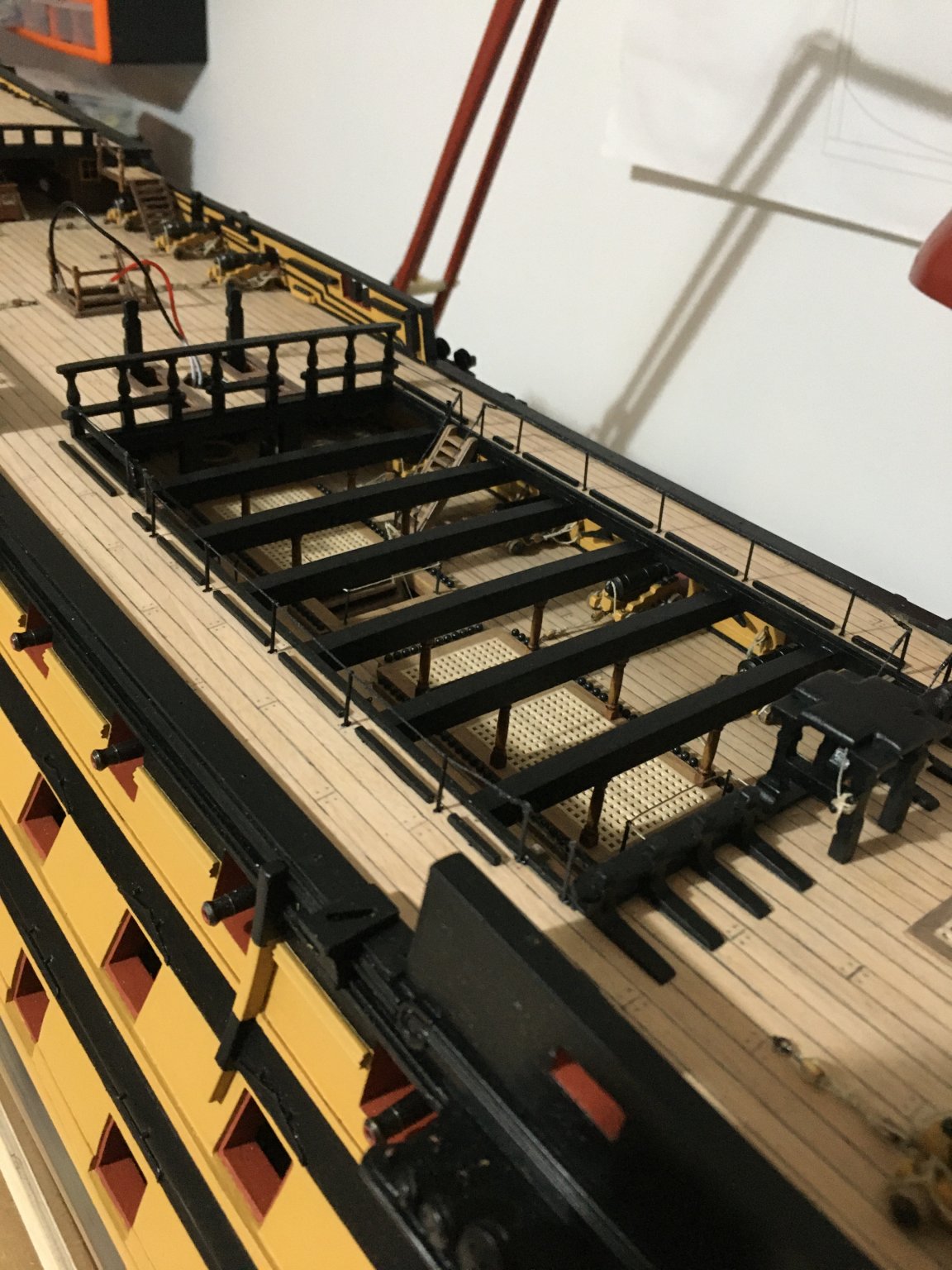
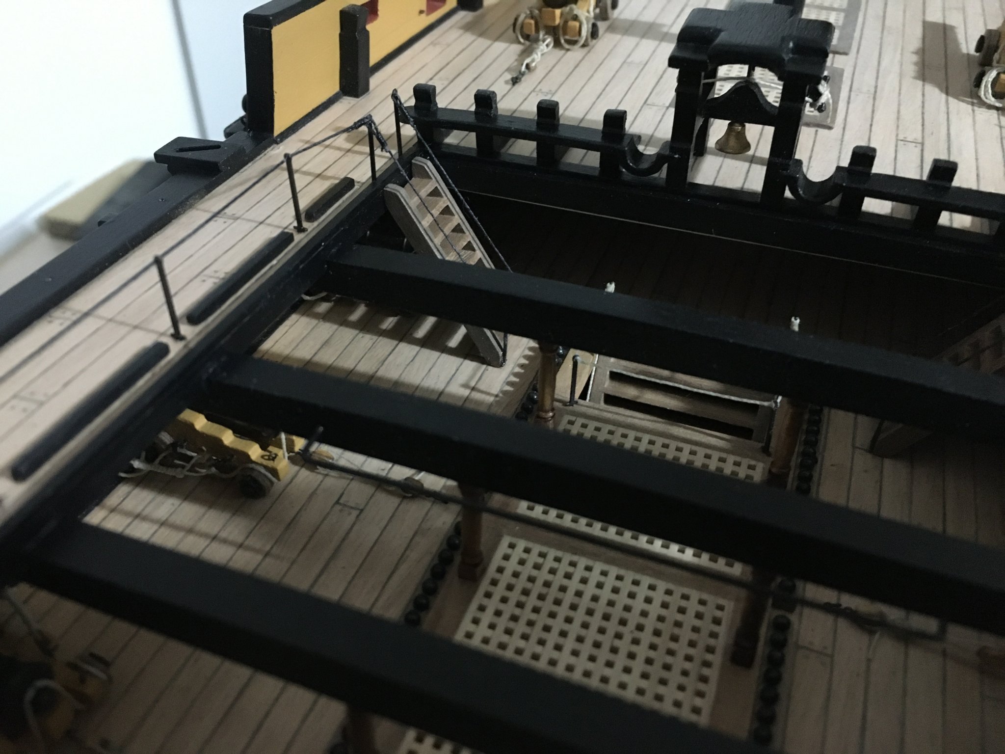
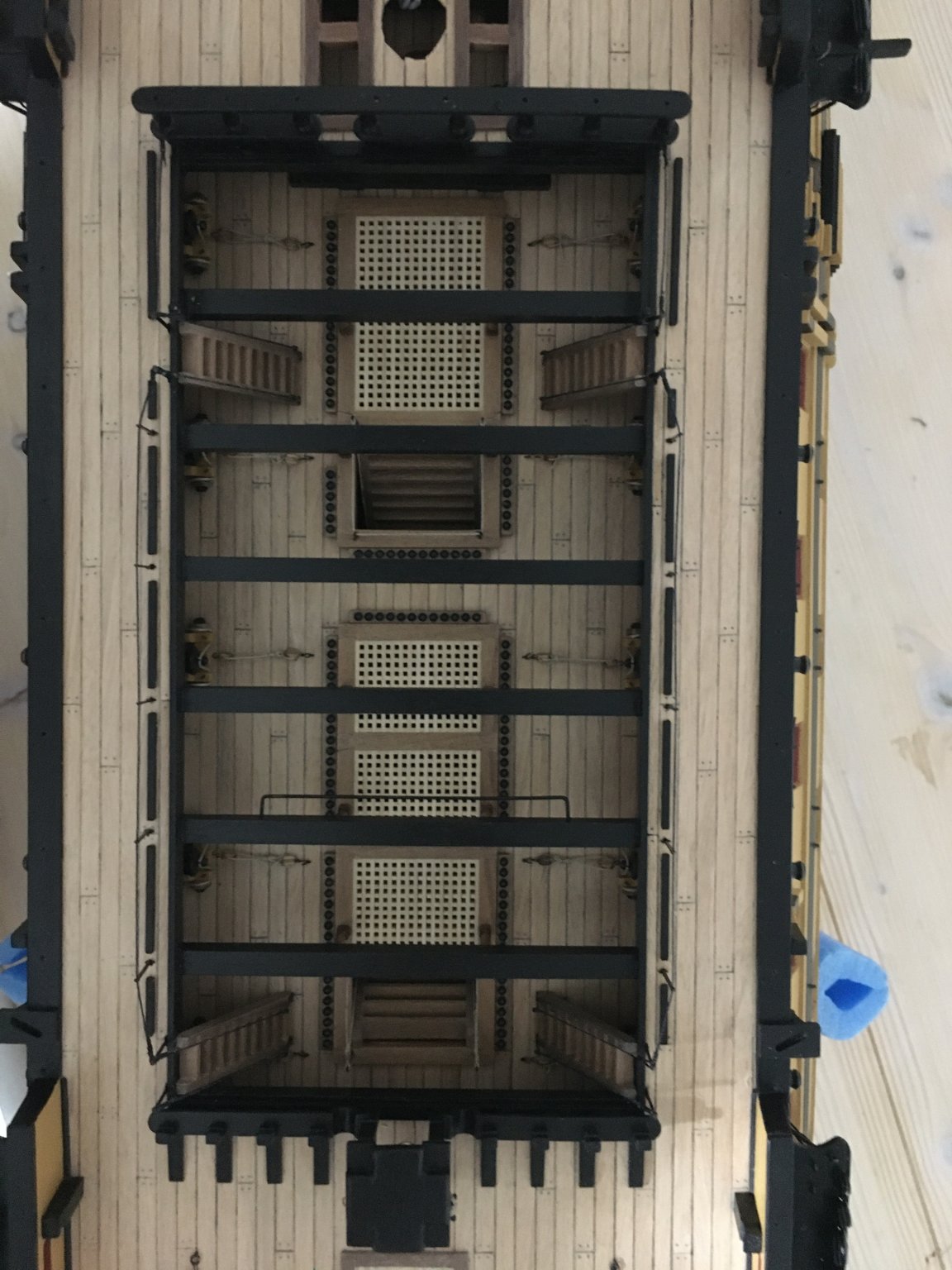
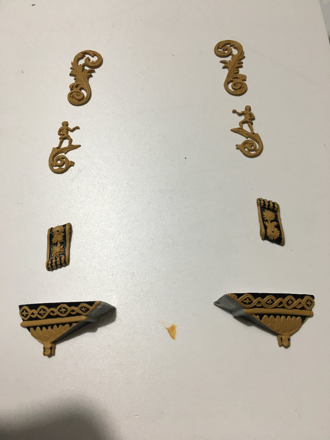
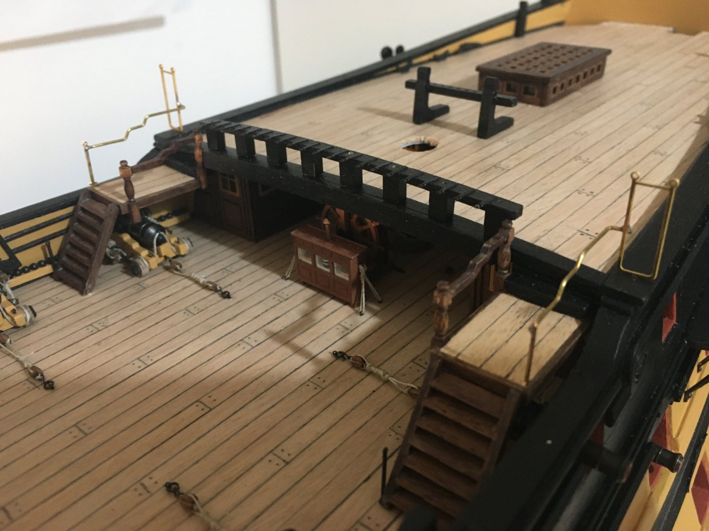
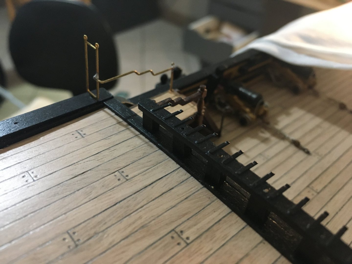
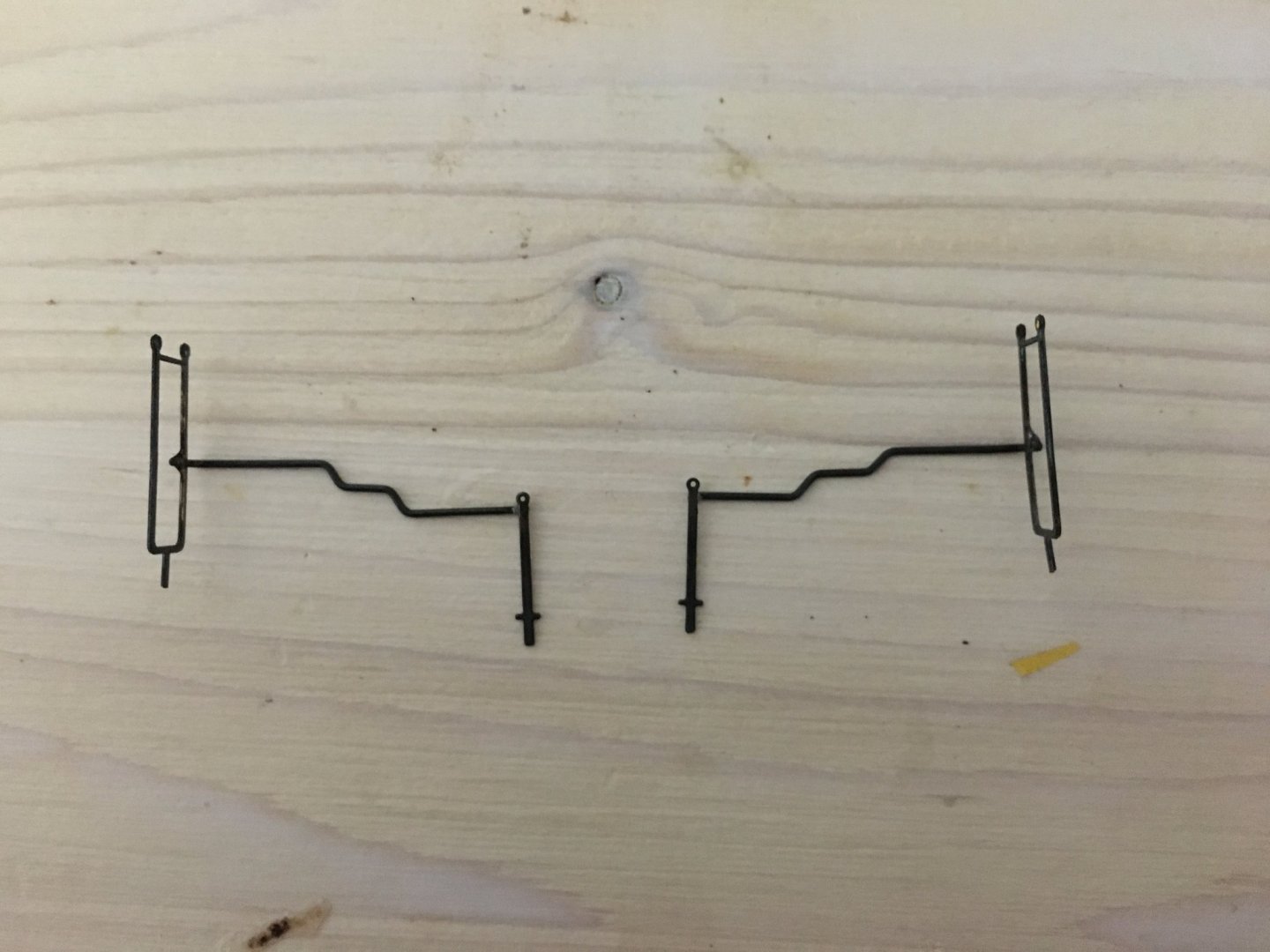
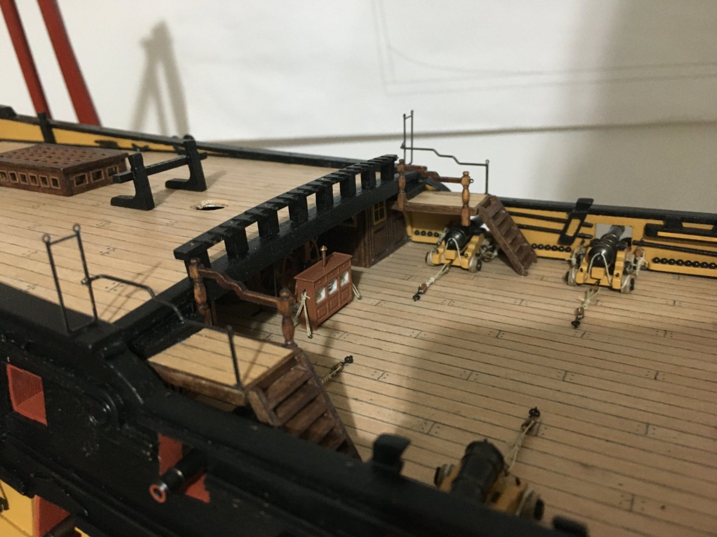
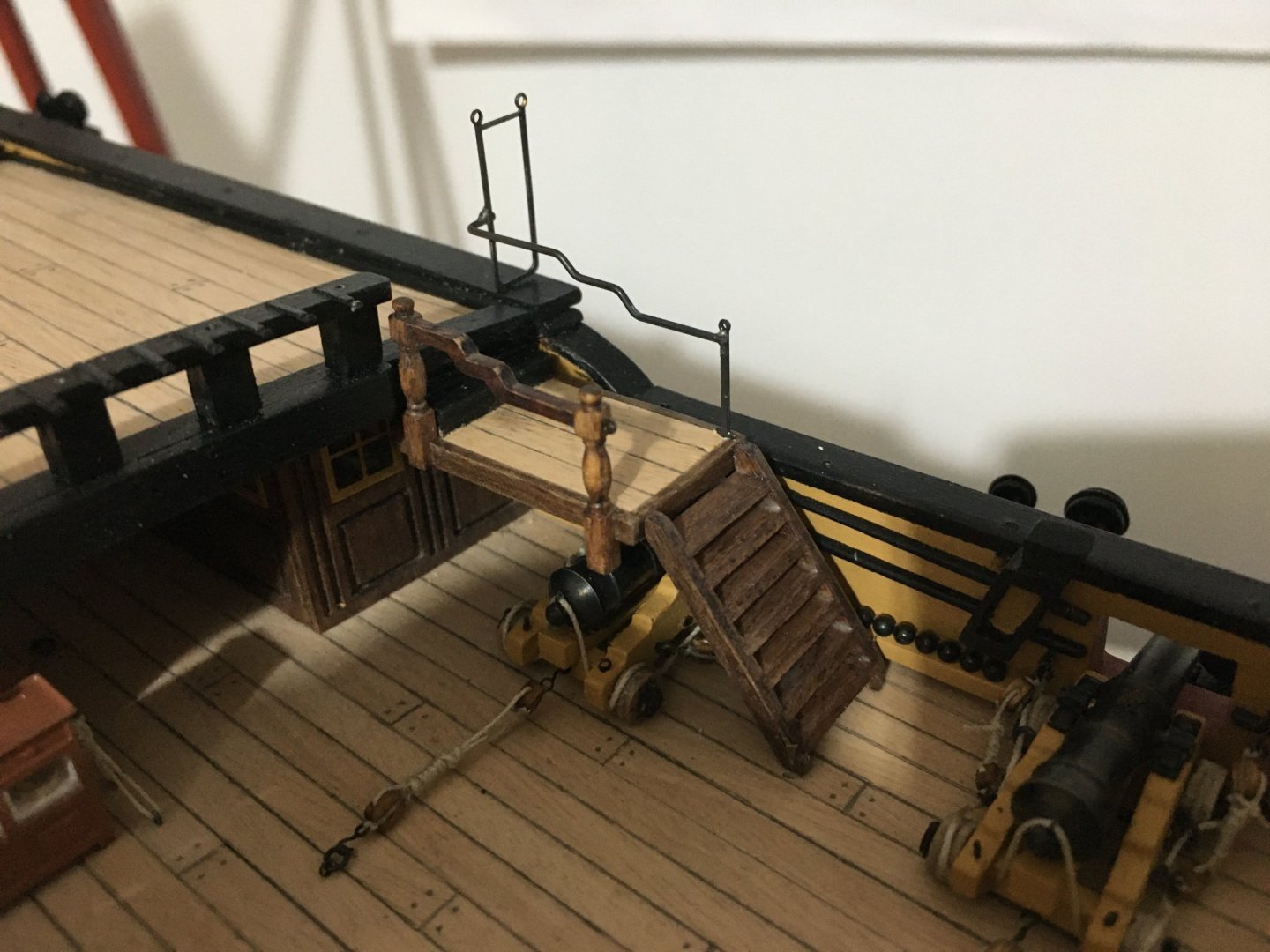
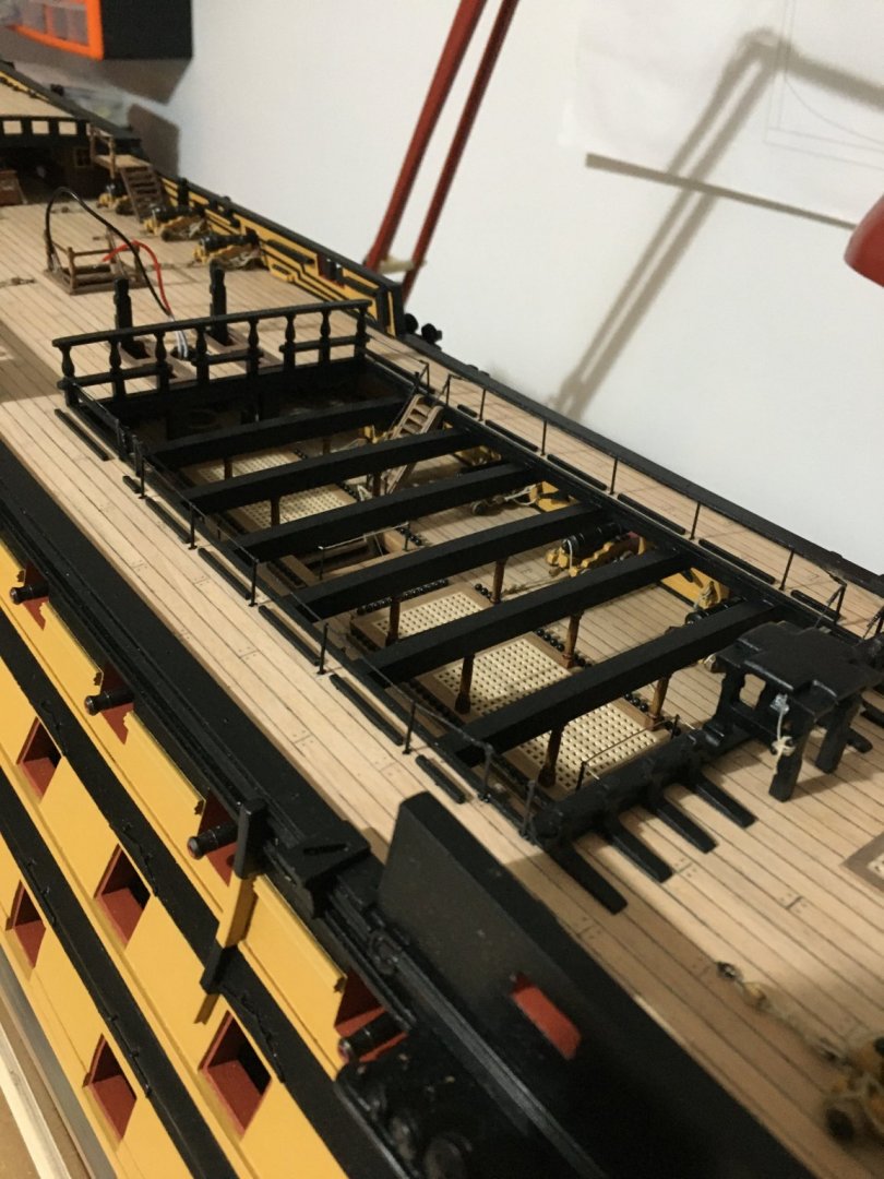
A small update, My aim was to continue and finish the stern fascia with the decorations and balusters. Painting the brass decorations was always a concern for me as they get scratched so easily, exposing the brass again. Browsing on the internet I found a product which according to their advert is fantastic, give a coat with it before the actual finish. It also had a video showing how to apply it. I will try to find it and upload it. So I decided to order it and use it on the brass baluster patters on the stern fascia and the side galleries. Erroneously I ordered them from Poland, from where apparently there are no flights for postal service at the moment, whereas postal service from UK is still on. I think it's worth waiting for the product before I continue finishing the stern fascia and the galleries. I will let you know how it went. I finished the rigging of the gunport lids, ready for the other end of the thread to be inserted in the tube on he hull side when fitted. Prepared the outer Poop Deck Hand Rail. Shaped and soldered the railing to the stanchion and the first hammock crane on the poop deck Blackened them. Dry fitted them. I will not fit them for now as otherwise I am sure I will nock them down a hundred times whilst doing other work on the deck. I have also blackened all the hammock cranes and prepared all the holes on the capping rails. It is important to keep the hammock cranes for each area separate from each other and marked as they all differ and if mixed it is no fun trying to identify which goes where. Fitted the Waist Deck Stanchions and rigged the ropes which were already attached to the stanchions at the base of the ladders. Thought I might as well paint the white metal stern decorations for the stern fascia and have them ready. I also painted the quarter gallery drop decorations. The extra metal parts still hanging to the decorations have to be removed to have a nicely finished sharp edge. The metal is very soft, I use a pointed exacto knife. The back part I left unpainted on purpose so that I will finish with some filler where it meets the underside of the gallery first, then paint it in place. As for the hammock crane netting I am still unsure if I should source some kind of tulle, as recommended on the manual, or if I should have a go at trying making them myself, which of course entails a lot more work. I have seen some in this forum made by the builders themselves and they look awesome. Robert


- 527 replies
-
- 10
-
-
- caldercraft
- victory
- (and 1 more)