Roger Pellett
-
Posts
4,519 -
Joined
-
Last visited
Content Type
Profiles
Forums
Gallery
Events
Everything posted by Roger Pellett
-
Almost 50 years ago I built an exposed frame POF model of a New. York Pilot Boat. This was a hull model only (it was fitted with stump masts). Materials; pear framing, keels, etc., boxwood planking, holly decking. I had a local auto paint supply shop make up quart of matt lacquer that I sprayed with an airbrush. The finish did not change the appearance of the wood and it has darkened noticeably with age. Roger
-
I remember a Scientific American article from many years ago examining the design of these large Galleys. One conclusion suggested that they might have been catamarans- two triremes linked together as a catamaran would allow efficient disposition of six banks of oars. This would also provide the stability necessary for the large heavy siege towers shown in the pictures. Roger
- 290 replies
-
- 5
-

-
- Quinquereme
- Finished
- (and 1 more)
-
A bit of degaussing cable trivia. During WW2 then Captain H.G. Rickover who went on to become the “father” of the navy’s nuclear propulsion program was the commander of the electrical section of the US Navy’s Bureau of Ships. A major problem that he was involved with was engineering of degaussing cables. At approximately the same time, my father and mother were temporarily living in Niagara Falls, NY where my father was responsible for construction of a pilot plant to manufacture a new material; Poly Vinyl Chloride. One day, he was approached by a Royal Navy Officer who was investigating use of PVC as an insulating material for degaussing cables. The British were having major problems with magnetic mines sown in the North Sea shipping channels by the Germans and natural rubber was in short supply due to Japanese control of Far East rubber plantations. PVC degaussing cable insulating material supplied to the Royal Navy was the BF Goodrich Co’s first war related product. It went on to become a major product with many uses. As far as I know, my father had no contact with either Rickover or the US Navy. That happened in the next generation. Roger
- 154 replies
-
- 5
-
-
- Enterprise
- Trumpeter
- (and 1 more)
-
You learn something new every day! Never heard of the Archimedes claw although he certainly knew lots about making ships float, or in this case sink. If these Galleys weighed 500 tons. Building a muscle powered mechanical device to lift even a fraction of this weight is remarkable. Roger
- 290 replies
-
- 5
-
-
- Quinquereme
- Finished
- (and 1 more)
-
I got a message today that Online Metals is now stocking materials from K&S Metals. I have no affiliation with either company. I have found Online Metals to be a reliable source of brass used for machining. As their name indicates they are easily located on the internet. Roger
-
I used Fiebing leather dye to stain rigging on my last rigged model-good stuff. In my experience conventional wood stains do not work well on the hard close grained woods that we ship model builders like to use. They are actually more like translucent paint. After retiring, my father started a business restoring antique furniture. He made his own stain- oil based artist pigments mixed in linseed oil. This is pretty much the same formula used in commercial stains. Water based stains would use a water soluble pigment and water. In both cases, the surface tension of the ingredients interferes with absorption into the wood. I believe that a better choice are the various dyes available. The chemists in our group can explain how these work. In addition to the Fiebing leather dyes, a wide selection of wood dyes are available from specialty woodworking houses. A bottle would probably stain a whole fleet of models. Roger
-
Eric, Yes, these vessels were designed empirically. These people apparently had powers of observation that far exceed ours. They incorporated features in their designs that they believed improved performance. However, my post is about Modern sources not ancient peoples. We don’t know that the builders of the San Marco believed that a curved keel improved transverse stability. Instead, this conclusion comes from modern sources, who are apparently unfamiliar with the theory of transverse stability. The only way to verify the effect of the curved keel would be to design two hulls, straight and curved keel and to run the calculations. BTW, my son-in-law works for Google on some sort of AI related project. I would not get into a boat that he designed! 😆 Roger
-
Increased Stability: I assume that this refers to Transverse Stability- resistance to capsize. This is a complex and often confusing subject. Transverse stability involves the action of two equal and opposite forces- gravity pushing down and buoyancy pushing up. The gravity force acts from the vessel’s center of mass, aka center of gravity. The buoyancy force acts from the center of buoyancy. Complicating this is the fact that for floating objects the center of gravity is usually ABOVE the center of buoyancy. Something else must therefore be in play or most ships would capsize. That something else is the underwater shape of the hull. When the vessel heels, the submerged shape of the hull changes, shifting the center buoyancy, causing its upward force to right the vessel. The amount of this “shift” determines whether the hull will be tippy or stable. Determining the “shift” requires calculus. The theory of hull stability and the mathematics to evaluate it were not discovered until the mid 1700’s, 600 years after the Venetians built the San Marco Ship. It is by no means obvious without elaborate calculations unknown in 1150 if longitudinal curvature of the keel had any effect on the transverse stability of the San Marco Ship. Roger
-
Elementary school clear glue?
Roger Pellett replied to modeller_masa's topic in Modeling tools and Workshop Equipment
I never gave much thought to glues. I have several models that I built 40-50 years ago. All were built using “yellow” hardware store glues; Elmer’s. All have held up fine with NO glue failures. I still use PVA “yellow” glue for wood-wood joints. Our Local stores stock Titebond. Roger -
Great to see this interesting project back on the Front Burner! Smokestack- I have been researching for my Benjamin Noble project. There are several possibilities- I read about one ship here on the Lakes where the stack was just a plain steel tube. Every so often it would get so hot that it would glow red! When that happened the watch stander in the pilot house would signal the engineer who would spray down the stack with water. There are also photos of stacks that clearly have internal liners. These could either be plain liners with a static air gap, or feedwater heaters as Ken posted. I doubt if the air gap was used to heat combustion as these plants pulled combustion air directly from the fire room via the large cowl ventilators on the boiler house roof.
-
In reality it’s a dropped strake. As the strakes approach the bow, the hull girth becomes less. By taking the place of two strakes very narrow planks are avoided. Same idea on a steel plated hull ( below the hawse pipe) Roger
-
New from Minnesota-MS Constitution
Roger Pellett replied to Minnesota.Tom's topic in New member Introductions
Maybe a Minnesota shipmodeling club. Summer meetings only! Roger -
Grant, Nice Work! Will this become part of a model railroad layout? If not, will there be a locomotive and or cars on your track? Roger
-
From what I have read, well into the 1500’s while States owned a few dedicated “King’s Ships” most large vessels served interchangeably as cargo carriers and warships. In time of war it was it was common practice for the King to add to his fleet by chartering or more accurately conscripting vessels within his reach. Furthermore, this lack of dedicated navies made the seas dangerous places during what passed for peacetime. Otherwise peaceful cargo vessels were also not above resorting to some privateering when the opportunity presented itself. It would, therefore, not be surprising to see warlike implements carried aboard otherwise peaceful cargo carriers. I think that the grapnels were used for boarding other ships. Roger
-
Looking good, Patrick; both the model and you!
-
In Chinese culture, the color red is associated with good luck. Brides often wear red.
-
US Naval strategy between the wars was heavily influenced by the Panama Canal. If the need arose to concentrate the fleet in either Ocean the ability of ships to fit into the canal locks shortened the time required compared to steaming completely around South America. I would assume that this would have influenced the design of these fleet carriers. Roger
- 154 replies
-
- 2
-
-
- Enterprise
- Trumpeter
- (and 1 more)
-
One of my father’s interests/ hobbies was raising Aberdeen Angus cattle. The hub of our farm was a large bank barn; hay loft on top cattle down below. When we bought the place the barn was painted red. We later had it painted white. The cattle didn’t appear to know the difference! 😀 Roger
-
Great picture and fascinating model. Are the dredge spoils piped ashore?
-
Billing Boats 1/144th scale Titanic
Roger Pellett replied to bdromstedt's topic in Plastic model kits
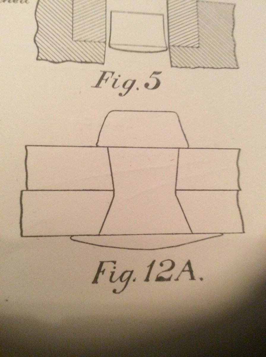
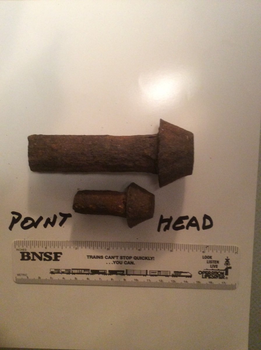
IMHO rivets are overdone by modelers anxious to include the smallest details. First of all, you are modeling to a scale of 1:144, so if you are viewing your model from a distance of 1ft, that is equivalent to looking at the real thing from a distance of 144ft. Second, unless you have an actual riveting schedule or better yet a plating expansion drawing for Titanic your riveting patterns will not be accurate. Joints between adjacent plates were riveted to withstand the stresses that were calculated to exist throughout the hull. Some joints were riveted with double rows, some with triple rows, and some joints in highly stressed areas with even more. The first photo below shows two actual rivets of the type used to join heavy plates in ship hulls. These are called Pan Head rivets. The rivet was inserted hot from the inside of the hull. It was held in place with a heavy backup tool while it was “closed up” by hammering from the outside. It needed to be closed up while still very hot as shrinkage while cooling was important to pull the joint together. The rivets used in building Titanic were driven by hand as her builder had not invested in pneumatic riveting tools. The second photo shows a cross section of a typical riveted joint used in shipbuilding. Note, the heavy Pan Head is on the inside of the hull. The observer looking at the hull from the outside would see the slight bulge of hammered metal. Roger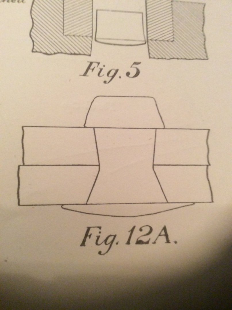

-
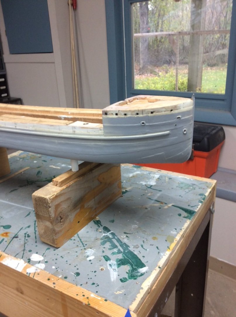
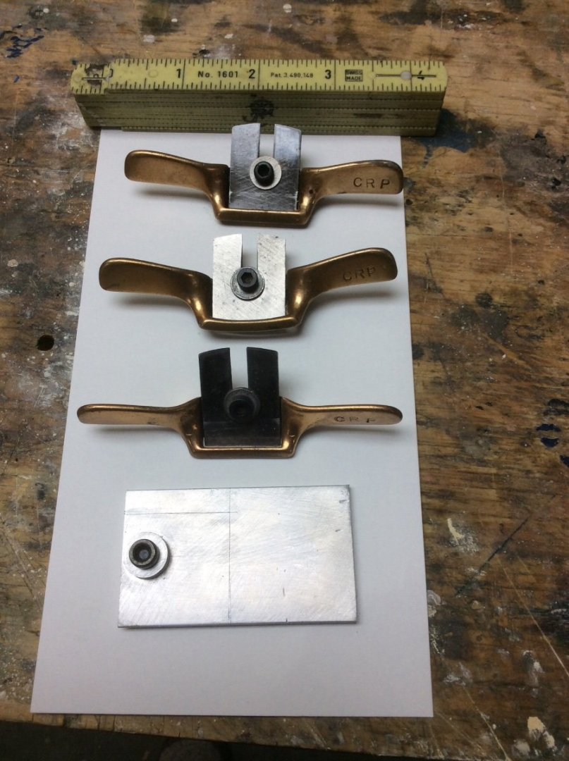
Very nice work! A couple of thoughts from a confirmed solid hull modeler: In looking at the body plan, all but one of the stations are what are known as True Views. In other words, looking at the plan what you are seeing is the actual shape of the section. Templates made directly from tracings of these sections will be correct. The exception to this is the transom. The view of the transom shown on the lines drawing is usually not a True View as the transom usually raked. While horizontal dimensions will be correct vertical dimensions will be foreshortened. The solution to this is an auxiliary view called a Transom Expansion where vertical dimensions are adjusted. These little brass spokeshaves are ideal for shaping carved hulls. I don’t believe that they are still made but are sometimes available used. Roger
-
From Nautical Research Journal, Volume 19- 1972 An extract from US Navy- “Fitting out of Naval Vessels 1842”. “ Black and White are the only colors for the outside of vessels. White, straw or green inboard.”
-
The idea of building a ship from a set of drawings prepared by a Naval Architect sitting in a design office is a relatively new idea. Although ships were built from drawings in the 1600’s, smaller vessels were often built in primitive ship yards by skilled artisans using formulae handed down by previous generations. For many vessels and particularly those built in the 1400’s design, therefore, cannot be divorced from the building process. You might say that these ships were designed as they were built. That is a major reason why Woodrat is using length of keel as a major design parameter. An owner would ask a Shipwright to build a vessel to stow a specified cubic volume of cargo; often large barrels called Tuns. The overall length of the vessel would be the sum of three major timbers; keel, stem post, and stern post. The easiest of these to measure was the keel, so this was the builder’s starting point. Many other dimensions would follow as ratios of keel length. If you asked out Fifteenth Century builder to build a ship of specified Length Between Perpendiculars, I don’t think that he would know what you were talking about or how to do it. Roger
-
Nils, I have a book about the freighters built by the Manitowac Shipbuilding Co. ( the company that built the Corsicana). Manitowoc built 38 Lake class three Island tramp steamships. The photos that I found all show the same arrangement of the cargo handling gear; Two tall masts, one in the center of the forecastle and one on the poop. Each of these has a long boom that reaches clear to the island structure. There are also four short King posts each with a short boom; one at each corner of the island. A surprising number of these sailed into the 1960’s and subsequent owners would have modified the cargo gear to suit the various trades involved.
-
If this is a working craft then rigging hardware including turnbuckles would be galvanized steel; a dull grey.