HOLIDAY DONATION DRIVE - SUPPORT MSW - DO YOUR PART TO KEEP THIS GREAT FORUM GOING! (Only 13 donations so far - C'mon guys!)
×


G.L.
-
Posts
1,553 -
Joined
-
Last visited
Content Type
Profiles
Forums
Gallery
Events
Everything posted by G.L.
-
 Very good job, Olha.
 -
Sloop from Roslagen by bolin - FINISHED - 1:50
G.L. replied to bolin's topic in - Build logs for subjects built 1851 - 1900
This has become a very nice model. congratulations! -
Unfortunately I have to put my project on hold for a few weeks. My son has asked me to help out in his company full time for a few weeks. However, full time for him means seven days a week, so there is no time left for model building for the time being. I hope to be able to continue with my clipper during October.
- 153 replies
-
- 4
-

-
- Ancre
- Bruno Orsel
- (and 2 more)
-
Your schooner has very nice lines indeed. Very nice work!
-
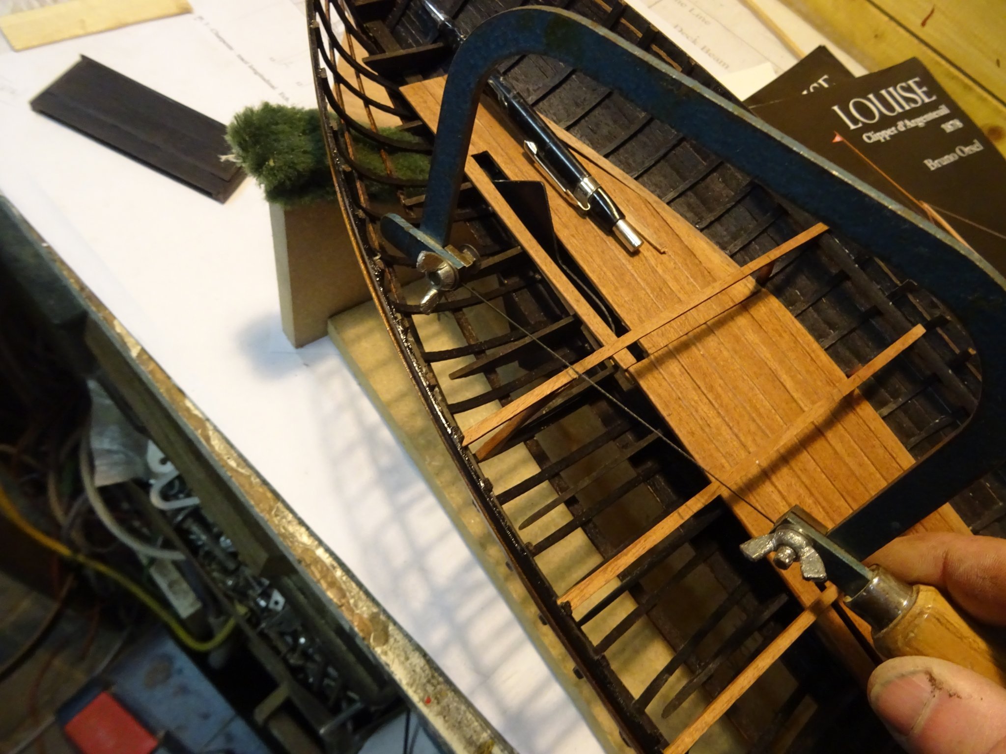
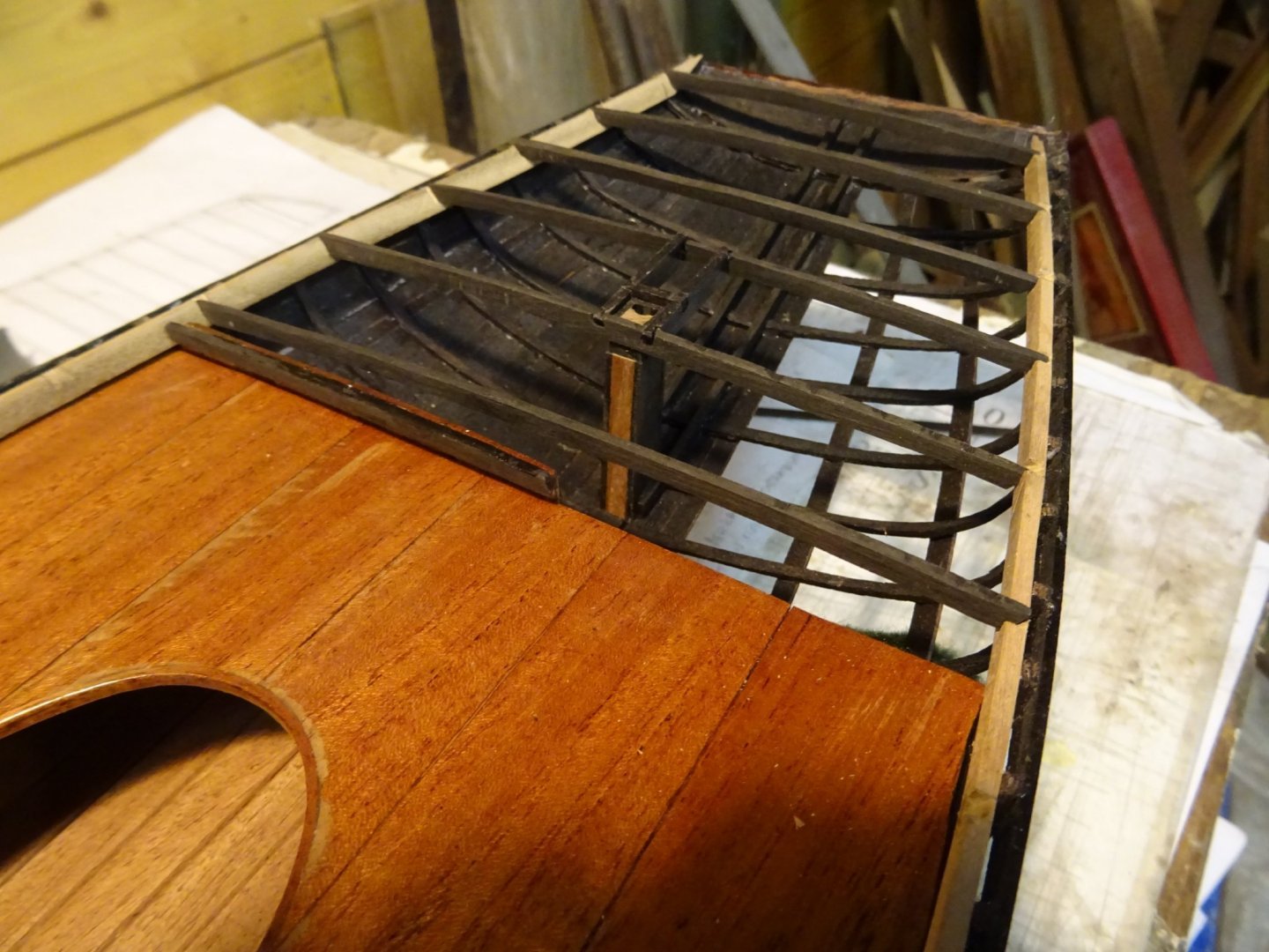
16. After deck beams Time to finish the deck beams behind the bulkhead. The deck beams round the helm port are reinforced with some carlings. The last deck beams are laid. Thank you very much for reading this log and for your likes and for your comments. Till next week!

- 153 replies
-
- 12
-
-
- Ancre
- Bruno Orsel
- (and 2 more)
-
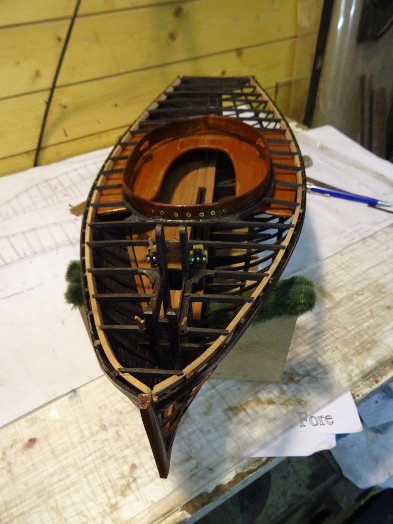
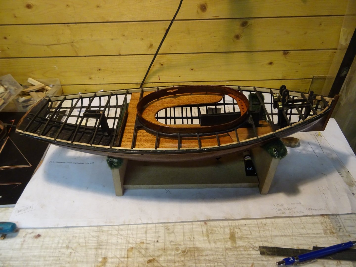
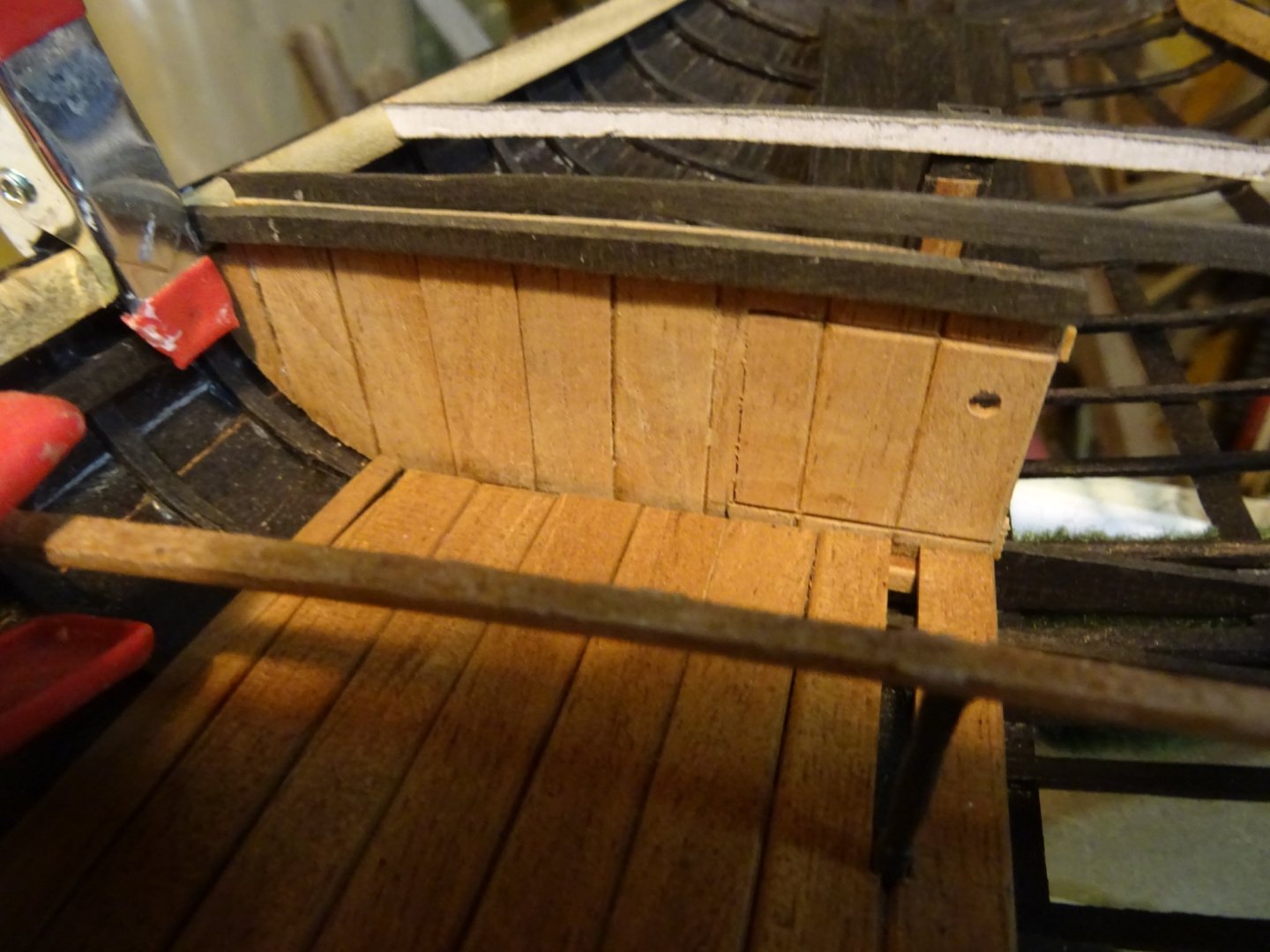
15. Bulkhead The cockpit area and the stern section are separated by a bulkhead. As my model is half anatomic, I will make a half bulkhead: from starboard side to midship. On the pictures you can see that I removed the thwart and the cockpit coaming arrangement, that is also the reason because I didn't glue the different sections in the hull yet. In the bulkhead, a panel, below the thwart gives access to the stern section.
- 153 replies
-
- 7
-
-
- Ancre
- Bruno Orsel
- (and 2 more)
-
The stitching on the last photo is done very accurately. The leach also looks very well sewn.
- 756 replies
-
- 3
-
-
- galleon
- golden hind
- (and 2 more)
-
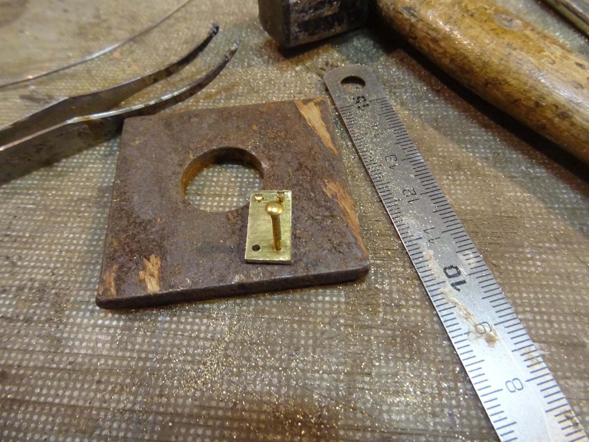
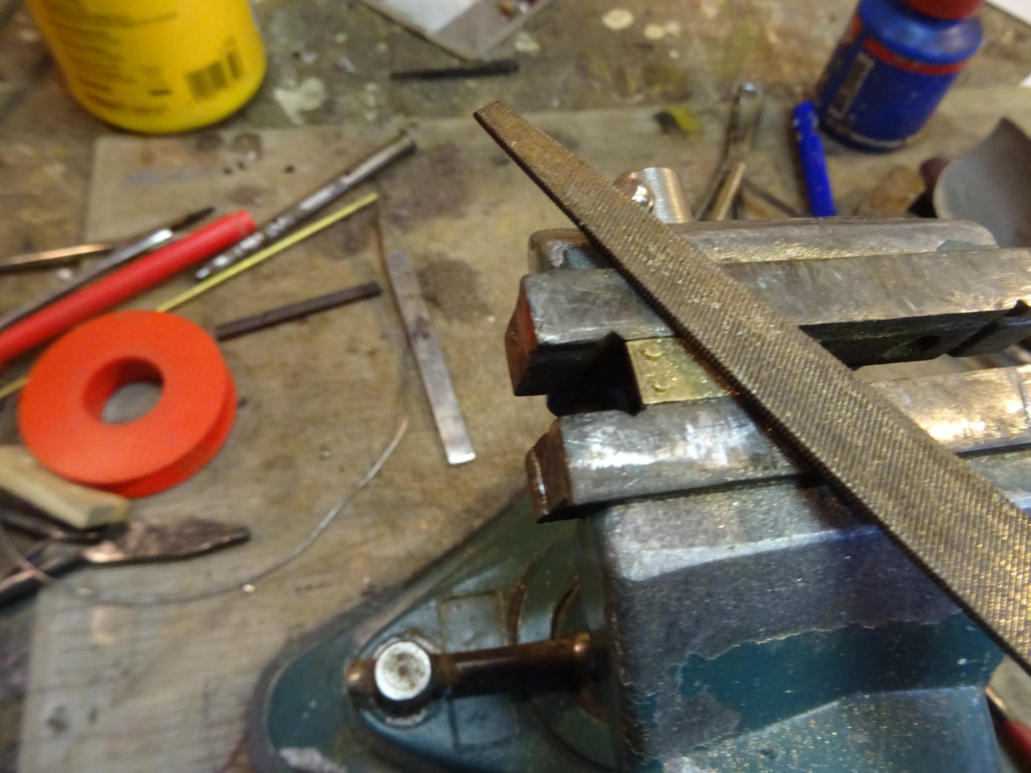
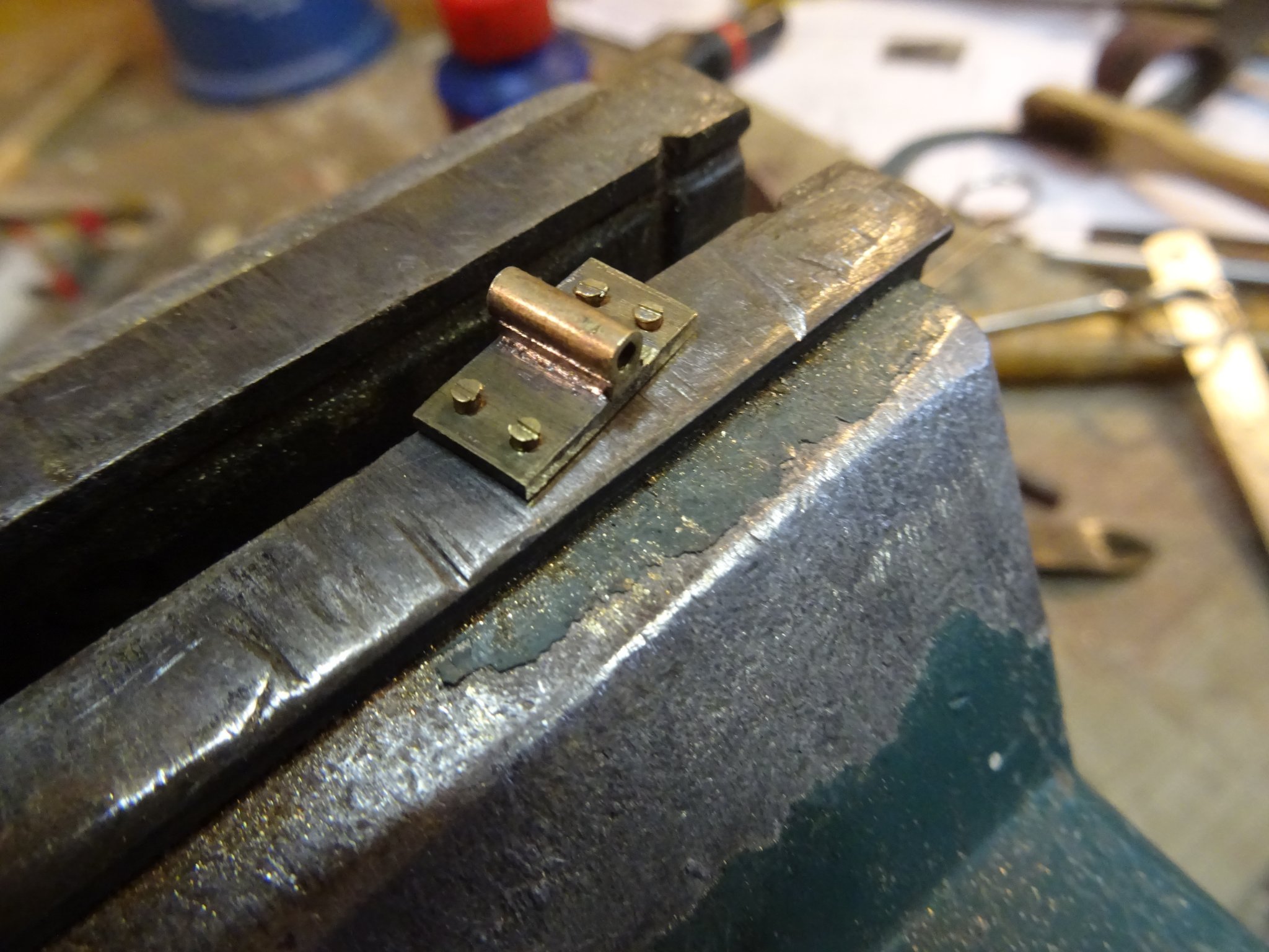
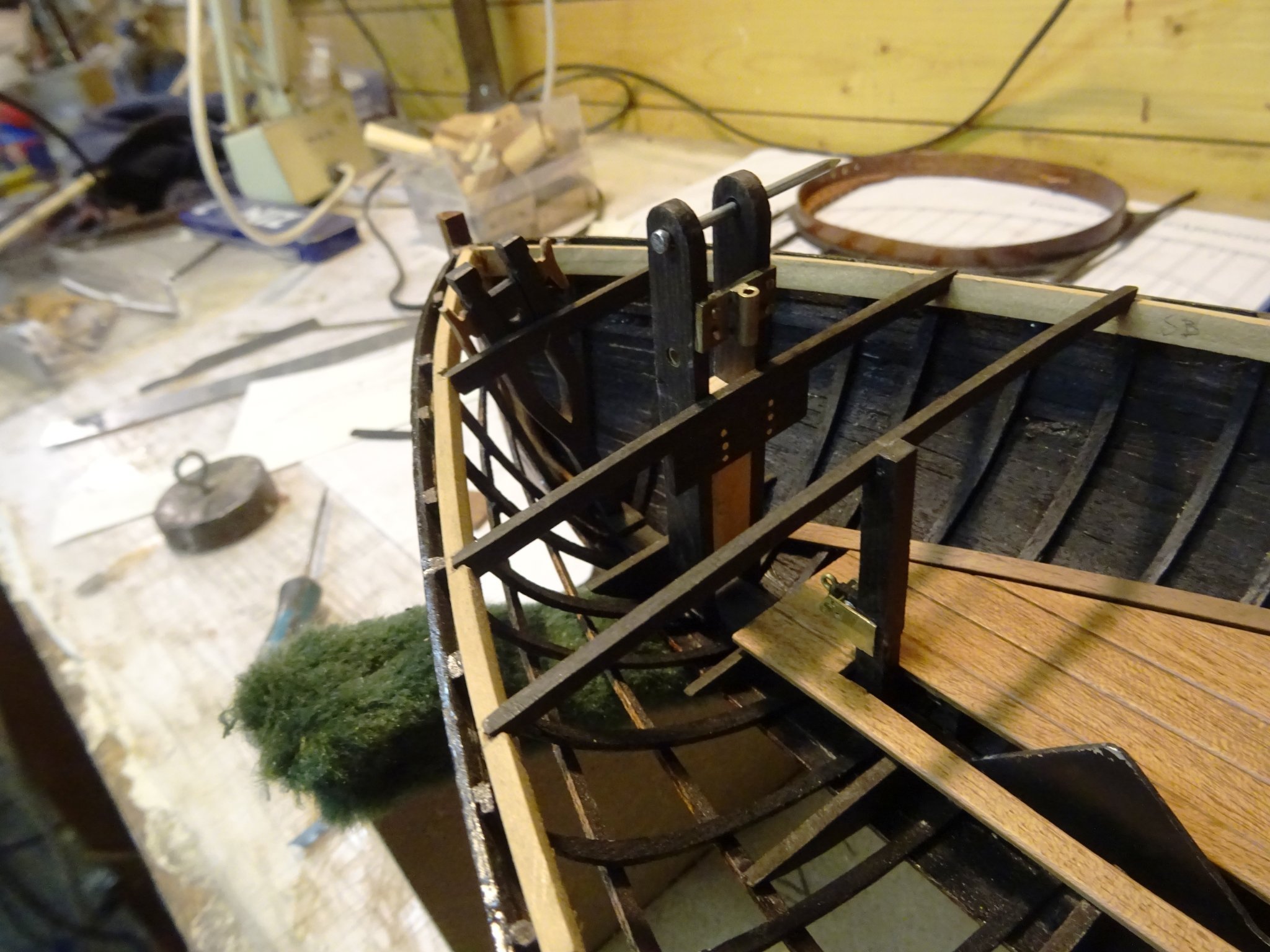
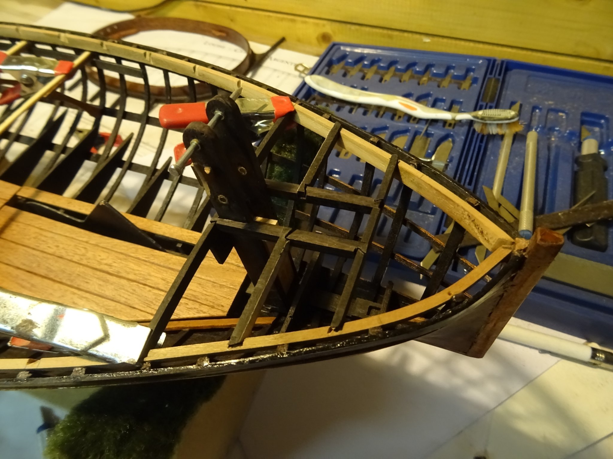
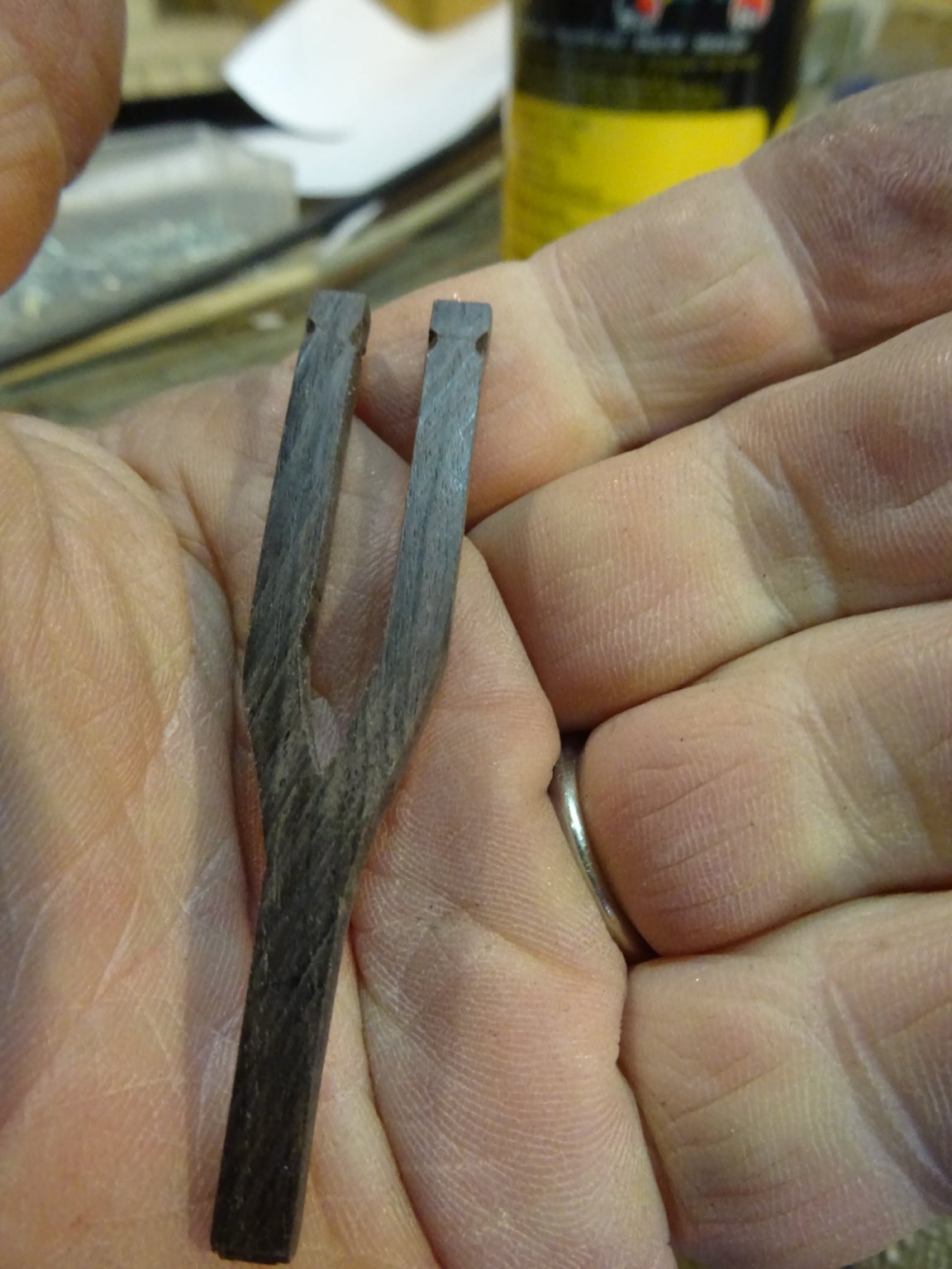
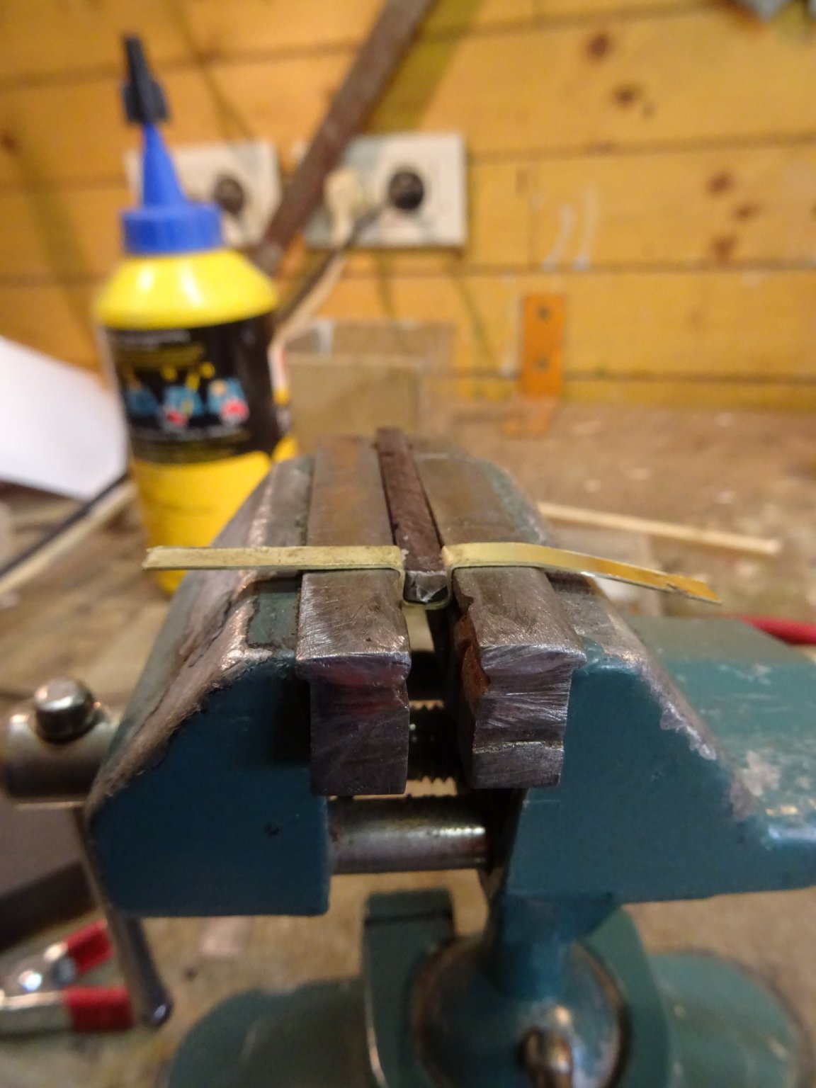
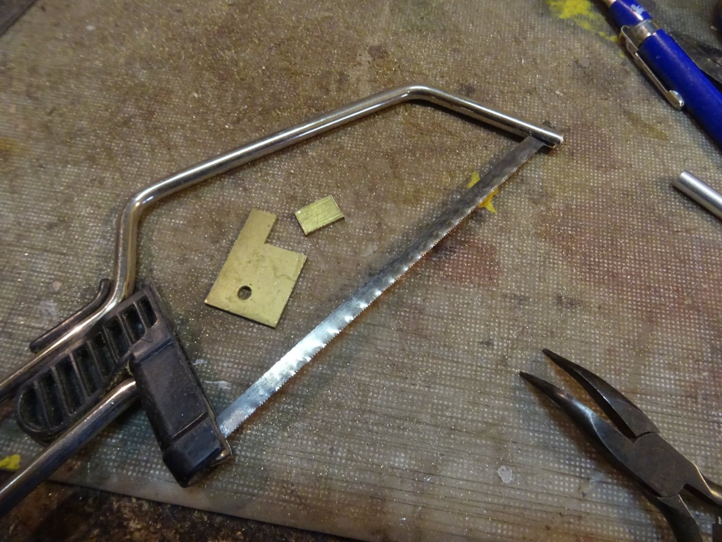
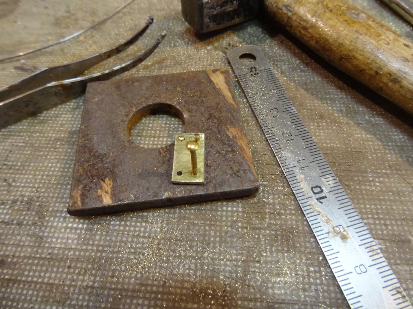
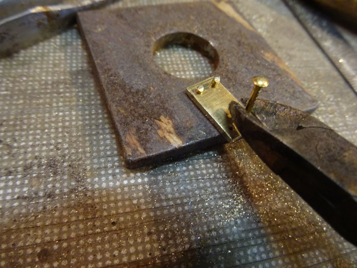
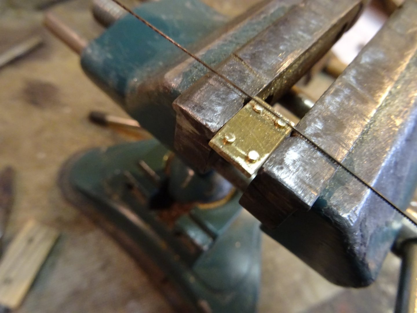
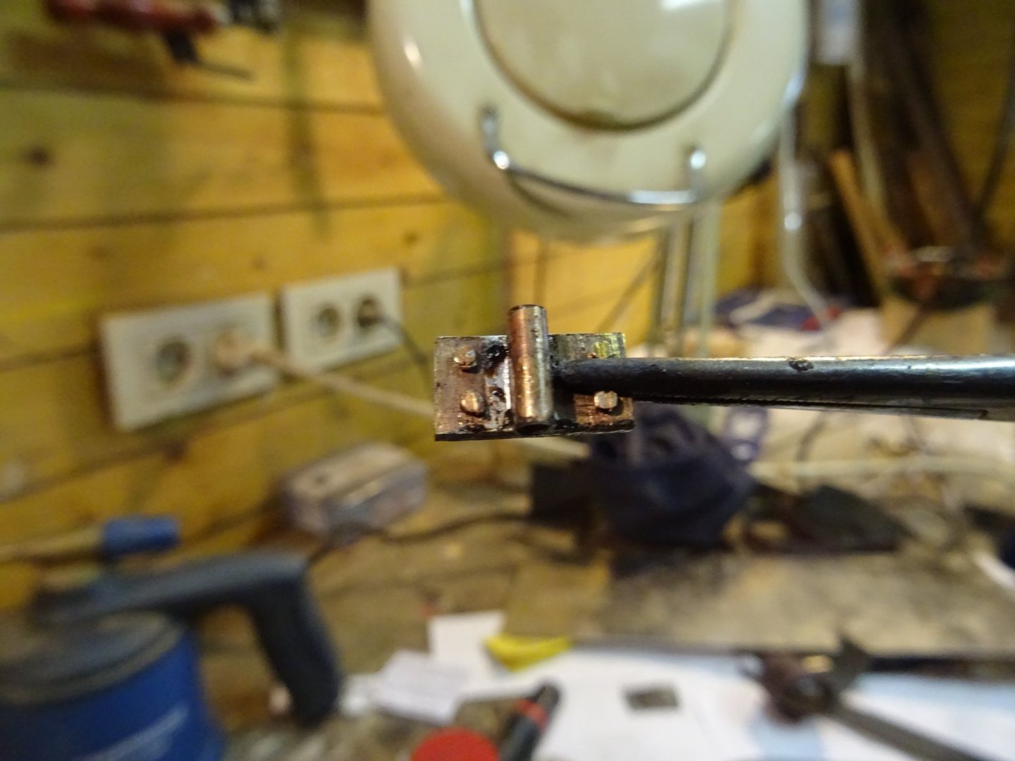
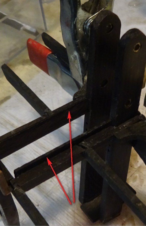
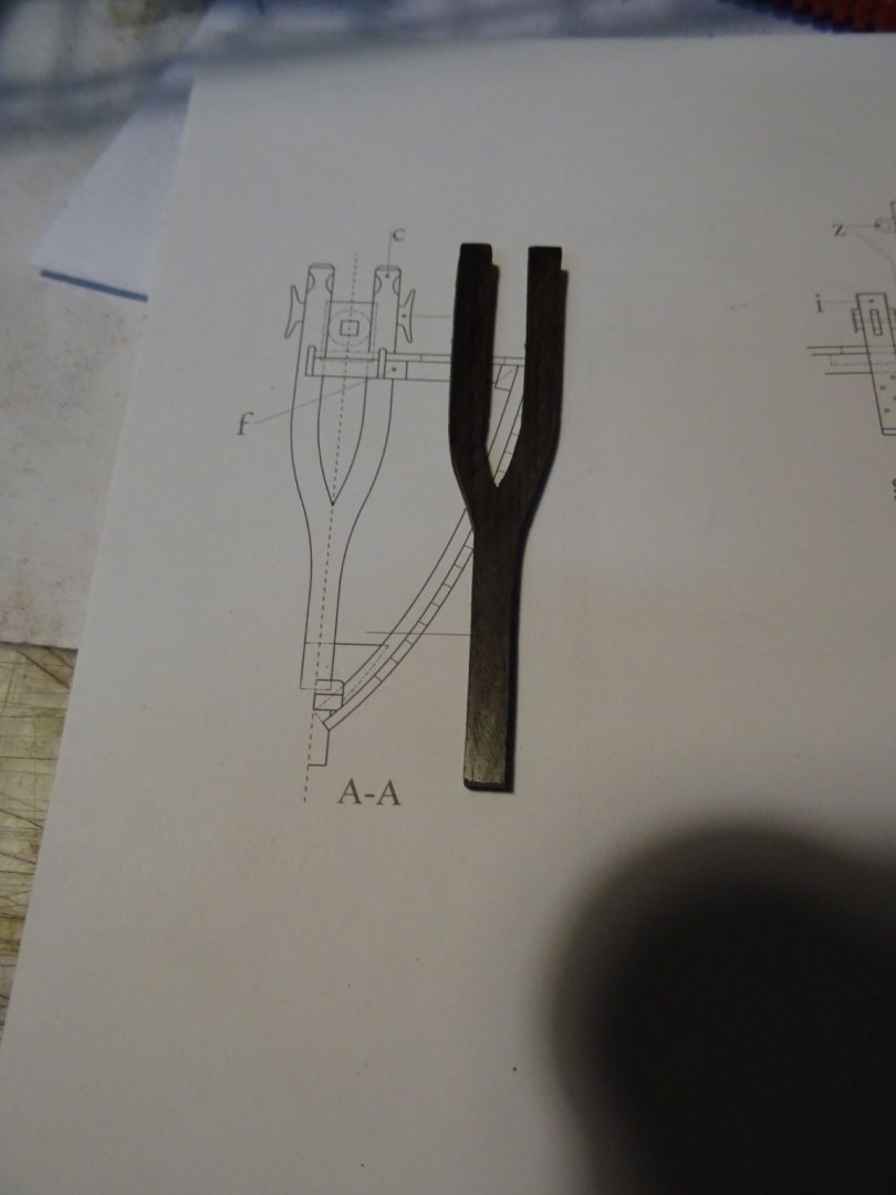
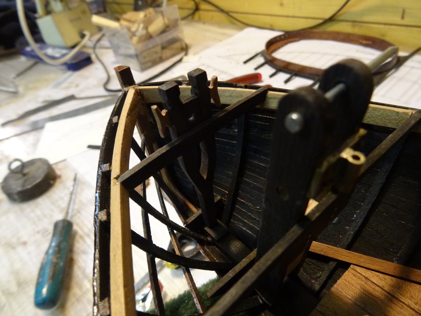
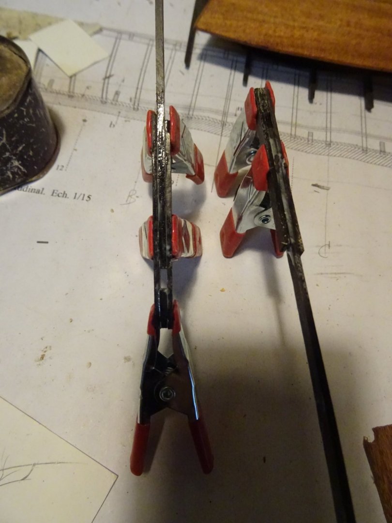
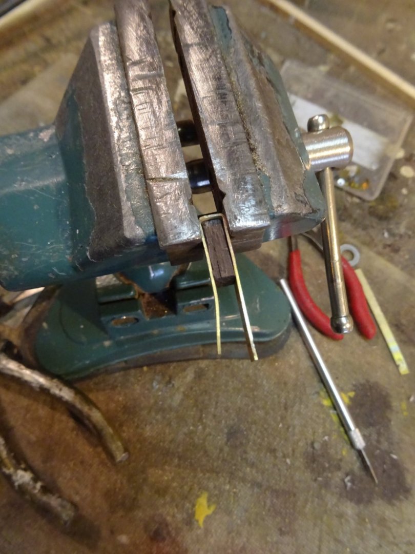
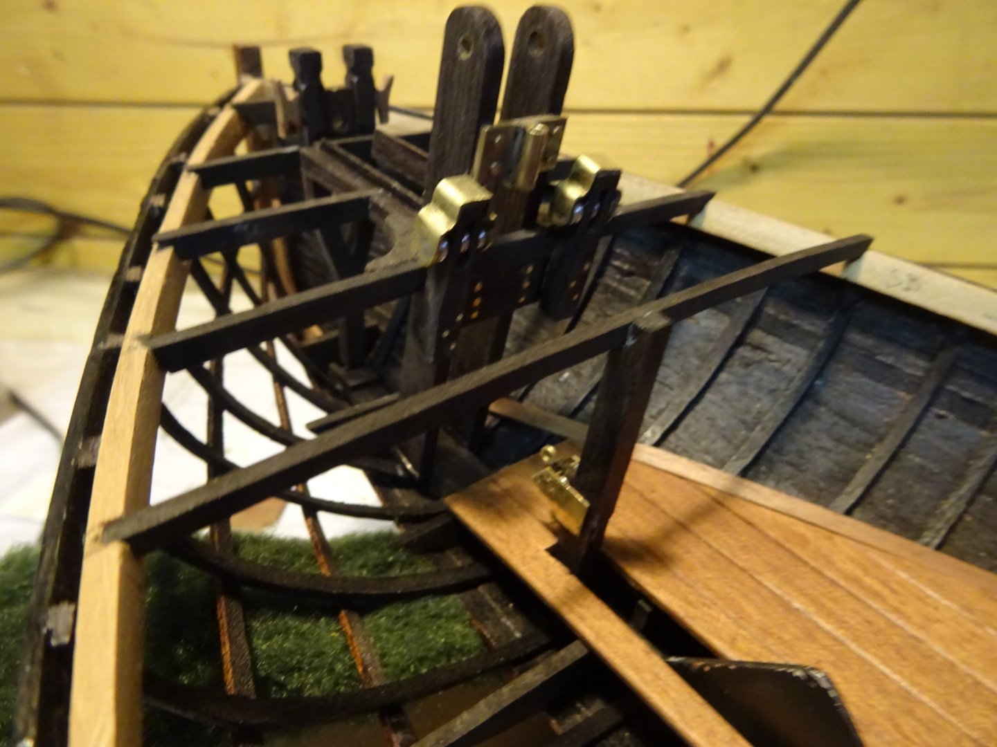
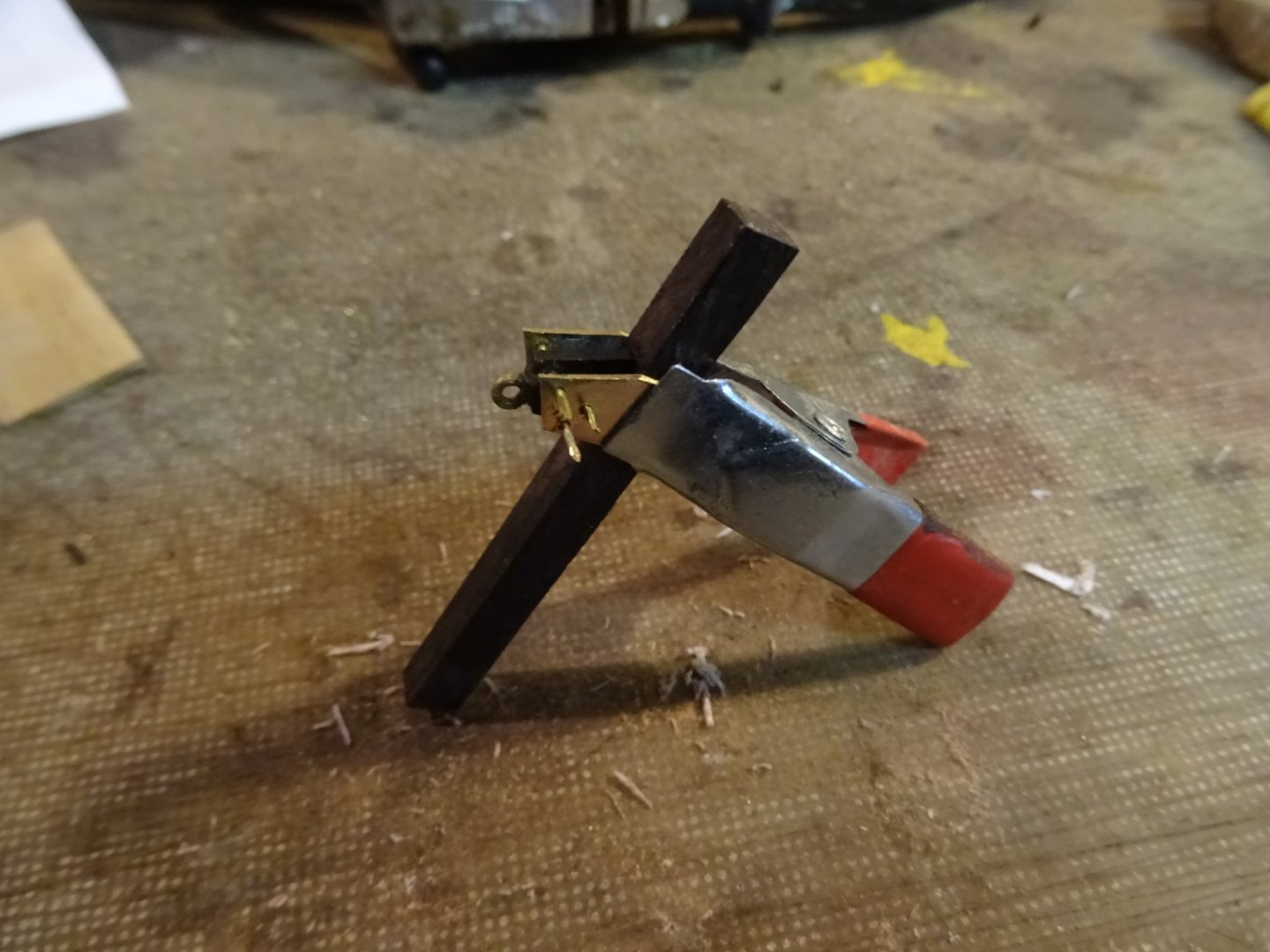
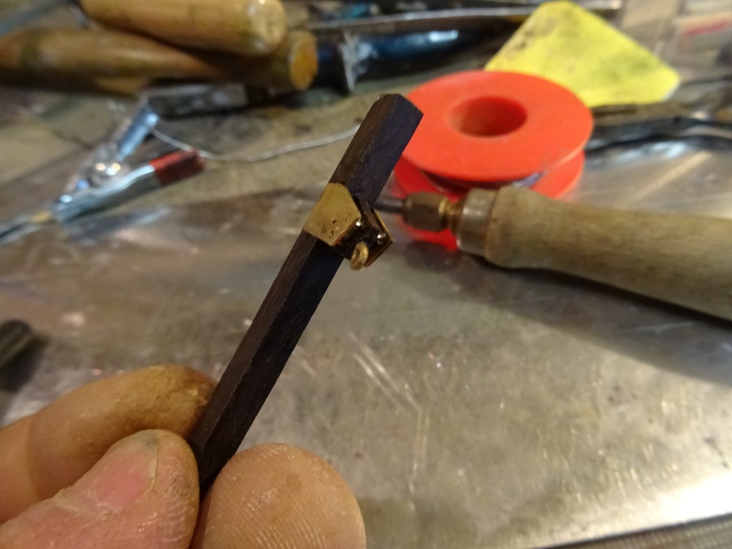
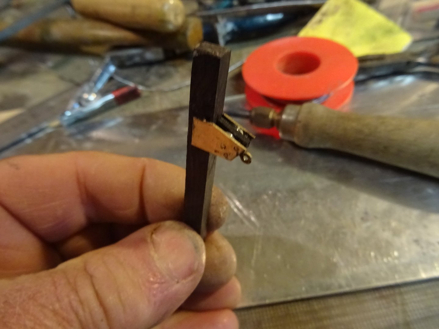
The mast step holds also the goose neck fitting. Sawing a piece of brass plate for the fitting. The goose neck fitting is attached to the mast step with four heavy screws. Imitating those screws: -Drilling four screw holes and knocking a brass nail in each of them. - Cutting the nails and filing them flat. - Sawing a (screwdriver)groove in each of the screws. - Soldering a piece of brass pipe on it as goose beck holder. The goose neck fitting attached to the step of the mast (The pale piece of wood at the bottom is a temporary spacer). In front of the mast stand bits. They consist of a fork shaped piece of ebony. Filing the heads of the bits The bits are placed against the second forward deck beam. To allow the mast to tilt freely from vertical to horizontal position, the lower part must be able to pass through the deck. An opening is provided for this in the foredeck. The carlings for the opening: Round the opening come small coamings. A bit hard to see on the picture. Just behind the mast stand two sheet bits with each thre sheaves to guide the sheets to the holes in the front of the cockpit coaming. I laminate the bits from three thin ebony slats to obtain a straight groove for the sheaves The cap of the sheet bits also contains two sheaves and must be folded into shape. The arrangement of mast step and bits. The whole will not yet glued definitively in the hull at this stage. Thank you very much for reading this log, for your likes and for your comments. Till next week!


- 153 replies
-
- 11
-
-
- Ancre
- Bruno Orsel
- (and 2 more)
-
Eberhard and Gary, thank you very much for your interest and your complements.
- 153 replies
-
- 2
-
-
- Ancre
- Bruno Orsel
- (and 2 more)
-
Thank you, Hakan. Tabernacle sounds indeed a lot better than my term. I will edit my log.
- 153 replies
-
- 1
-
-
- Ancre
- Bruno Orsel
- (and 2 more)
-
Exciting! The first sawdust of a new project.
-
Patrick, As a reward for your restoration work on the sewing machine you will receive this Tribute to Singer from me: https://www.youtube.com/watch?v=NQfq1GcYzu0
- 756 replies
-
- 3
-

-
-
- galleon
- golden hind
- (and 2 more)
-
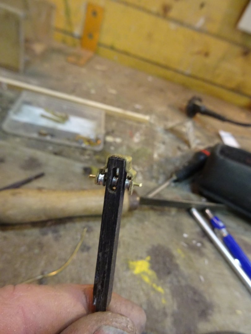
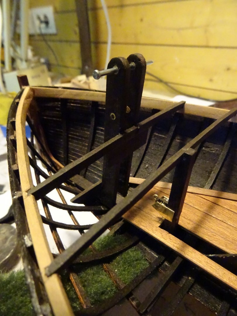
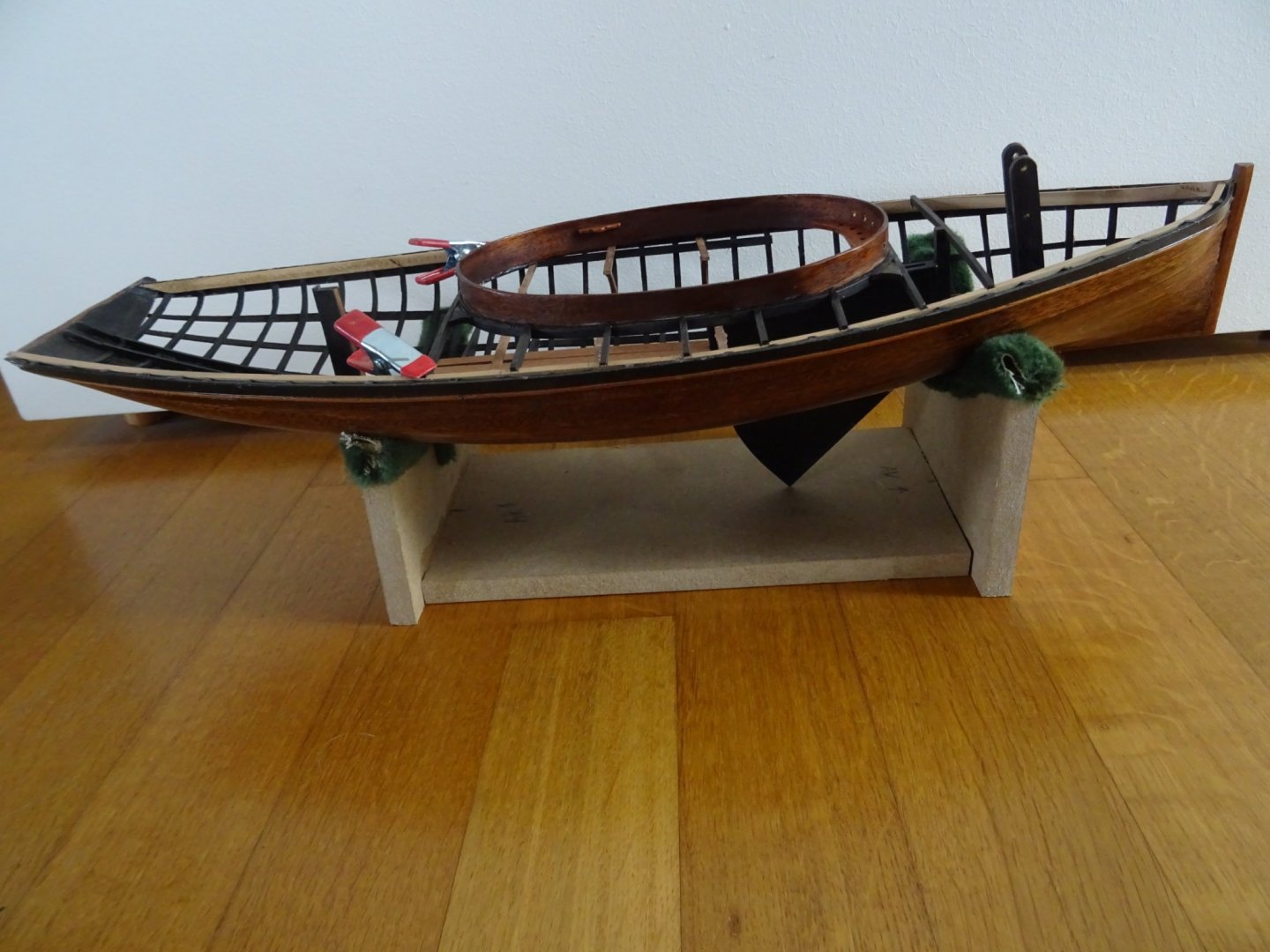
14. Step of the mast and peripherals Assembling the step of the mast. There are two pairs of holes running through the mast step (which now have nails through). The top holes are for the pivot spindle around which the mast can tilt, the bottom one for the pin to lock the mast. Fitting the step of the mast. Now that the bottom nail has been removed, you can see that the holes for the spindles have been reinforced with a piece of brass tube. The step of the mast and the mast erecting sheaves. The center board case is taken away to give a clear view. Overview: Thank you very much for reading this log and for your likes . Till next week!


- 153 replies
-
- 9
-
-
- Ancre
- Bruno Orsel
- (and 2 more)
-
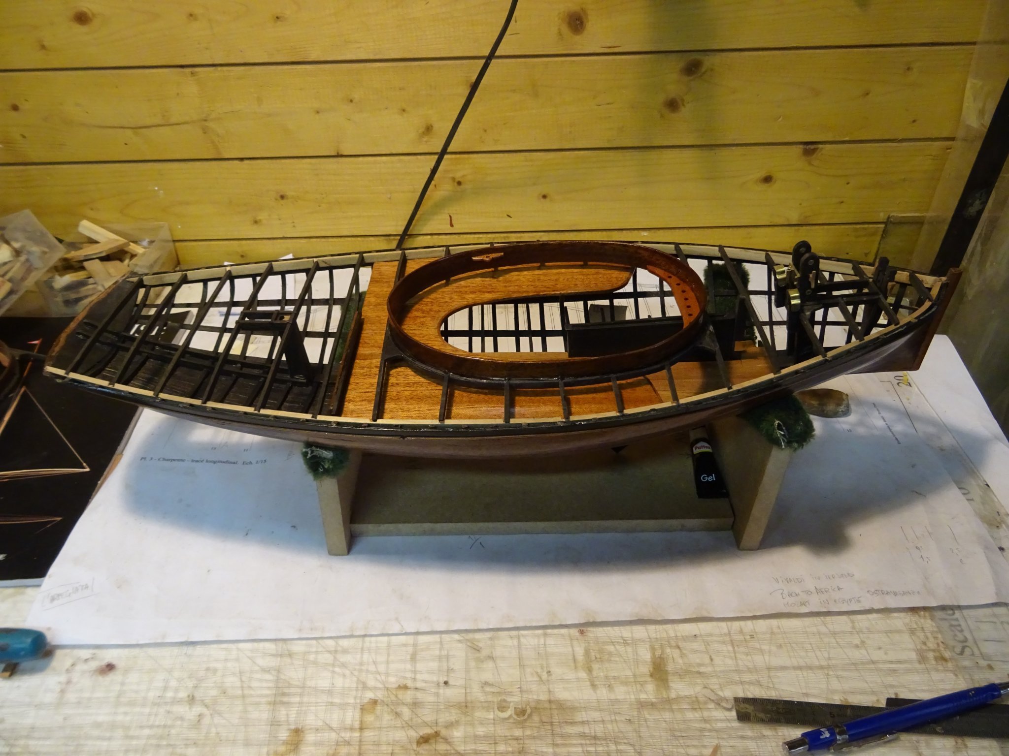
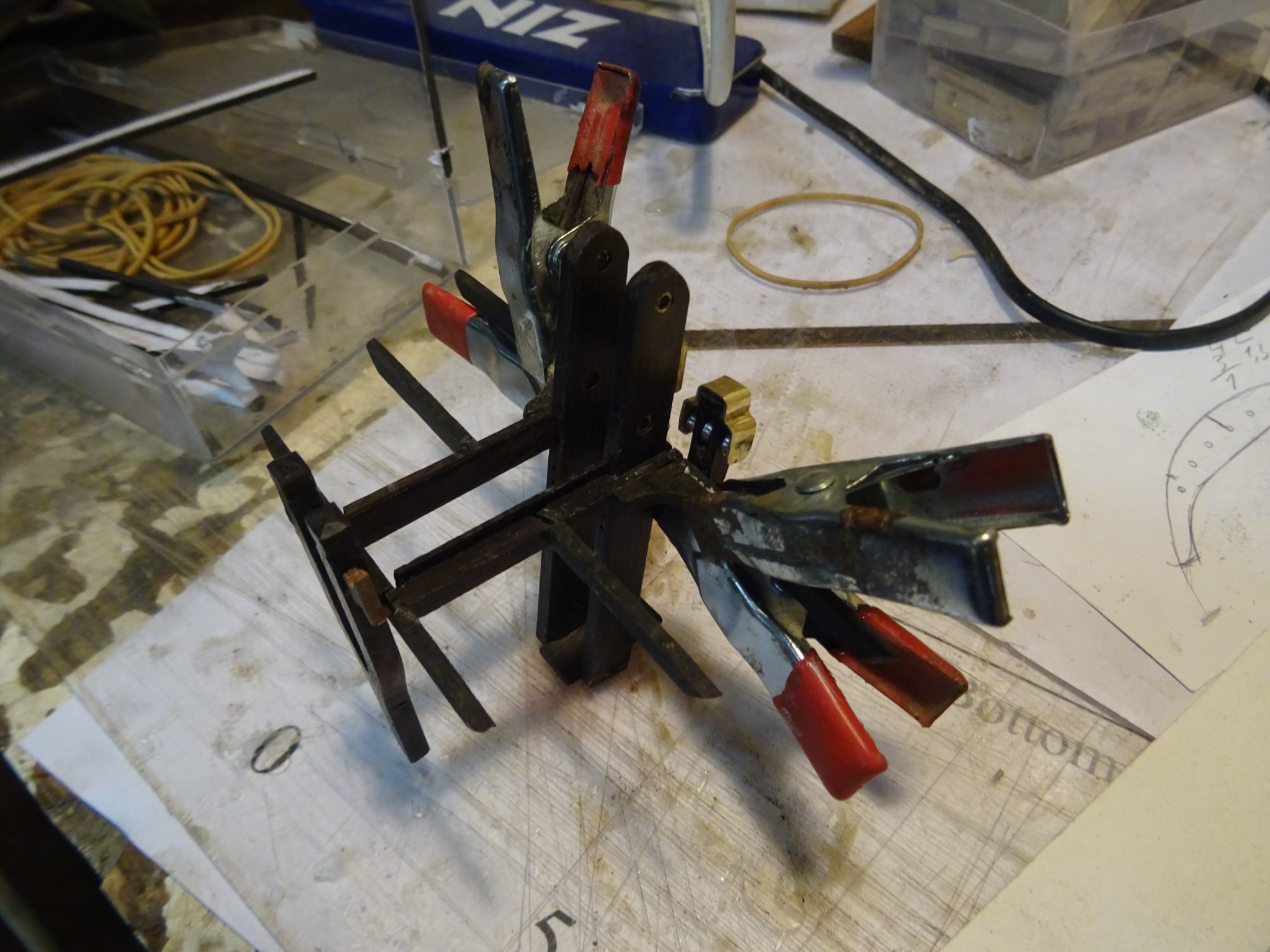
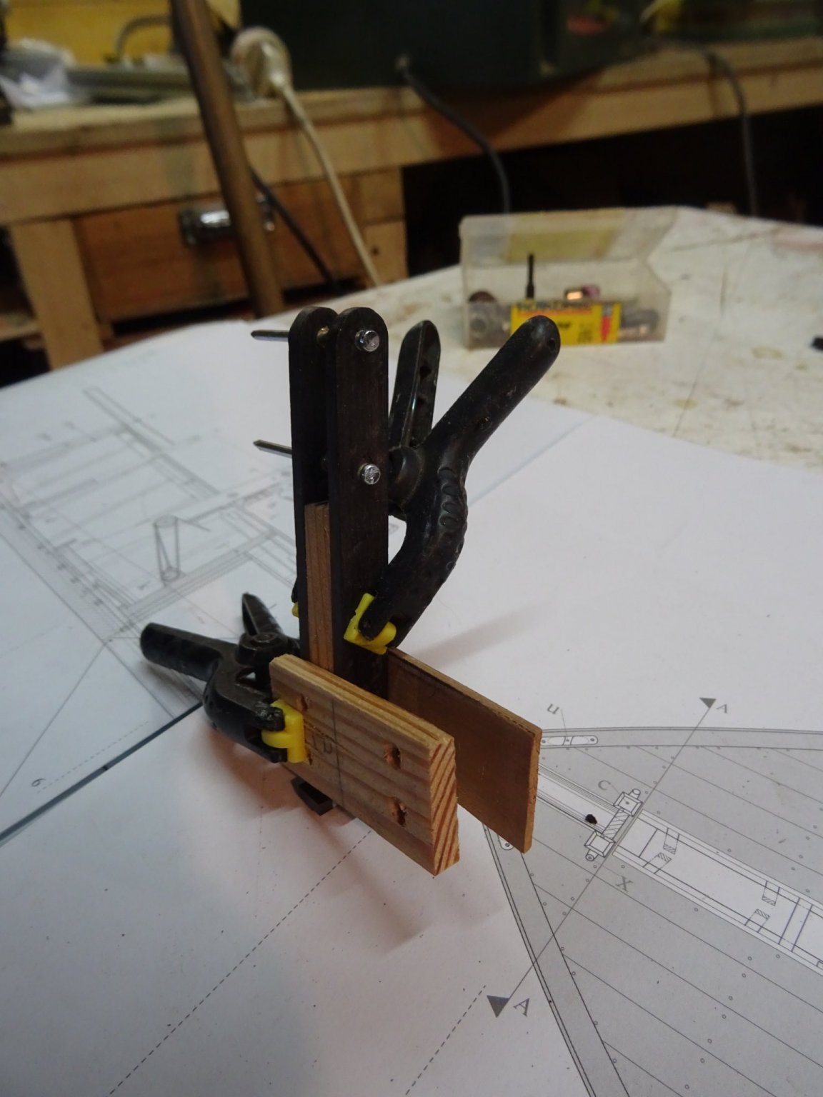
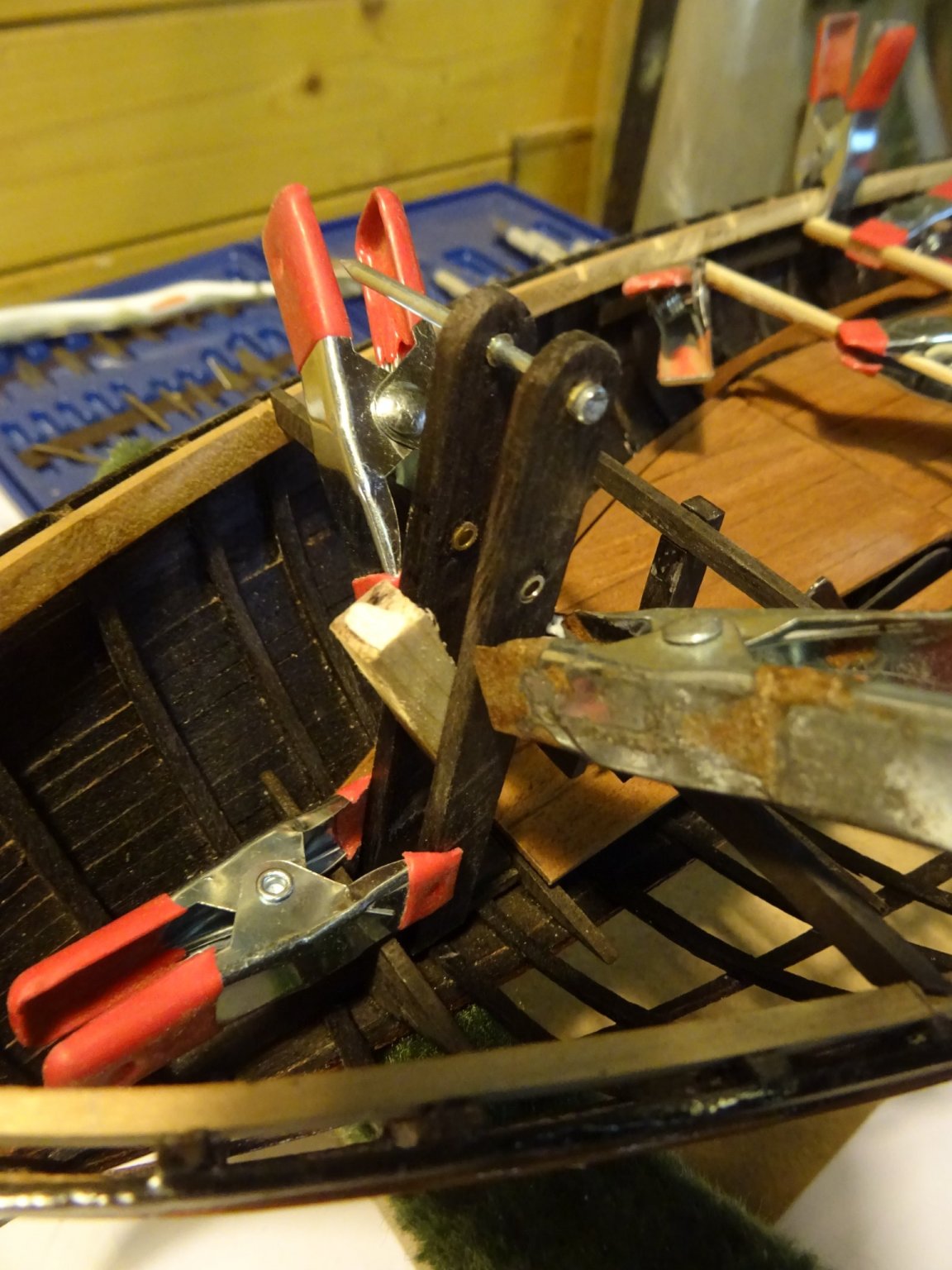
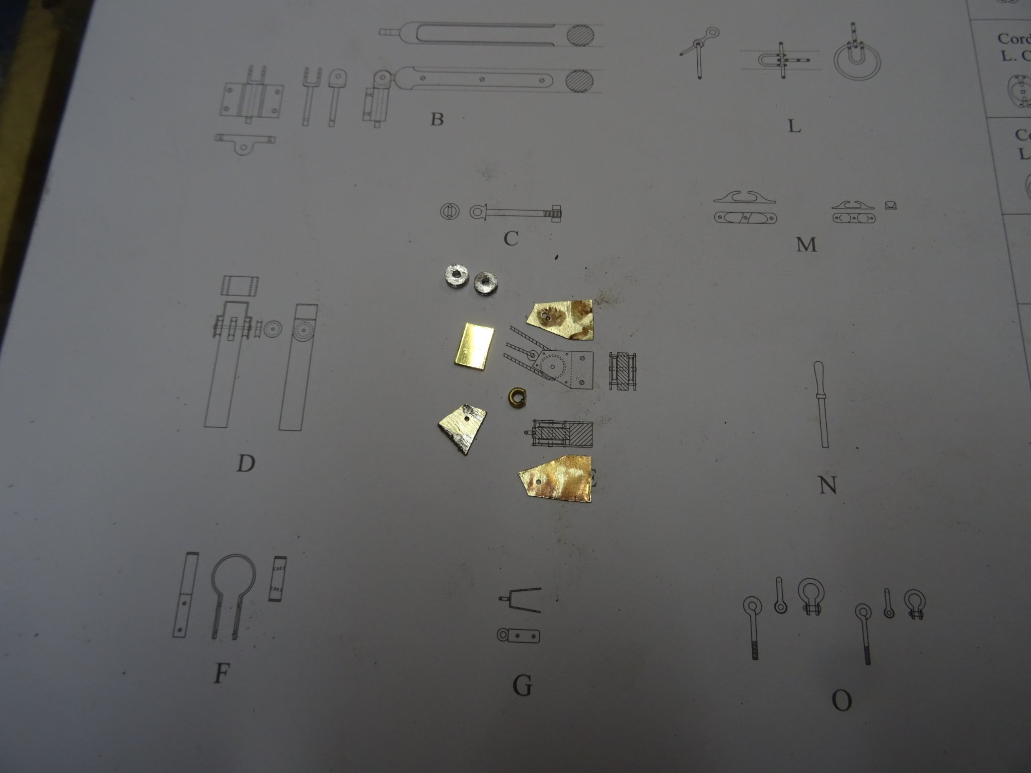
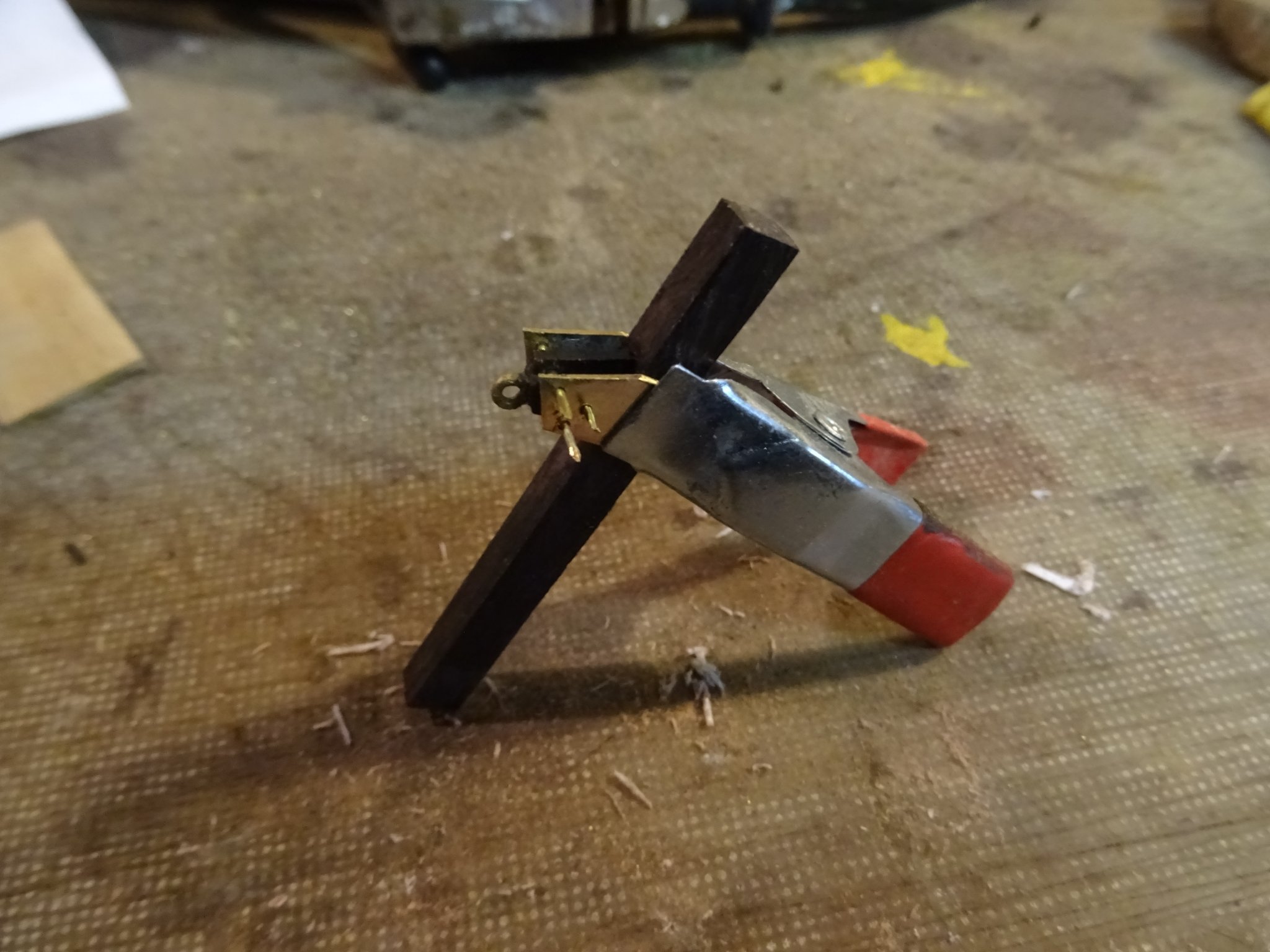
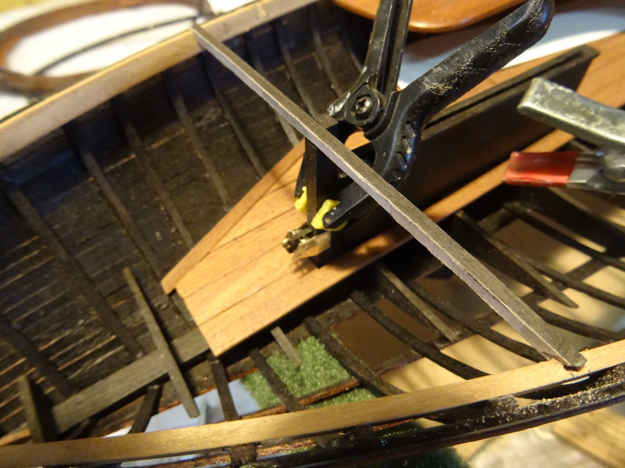
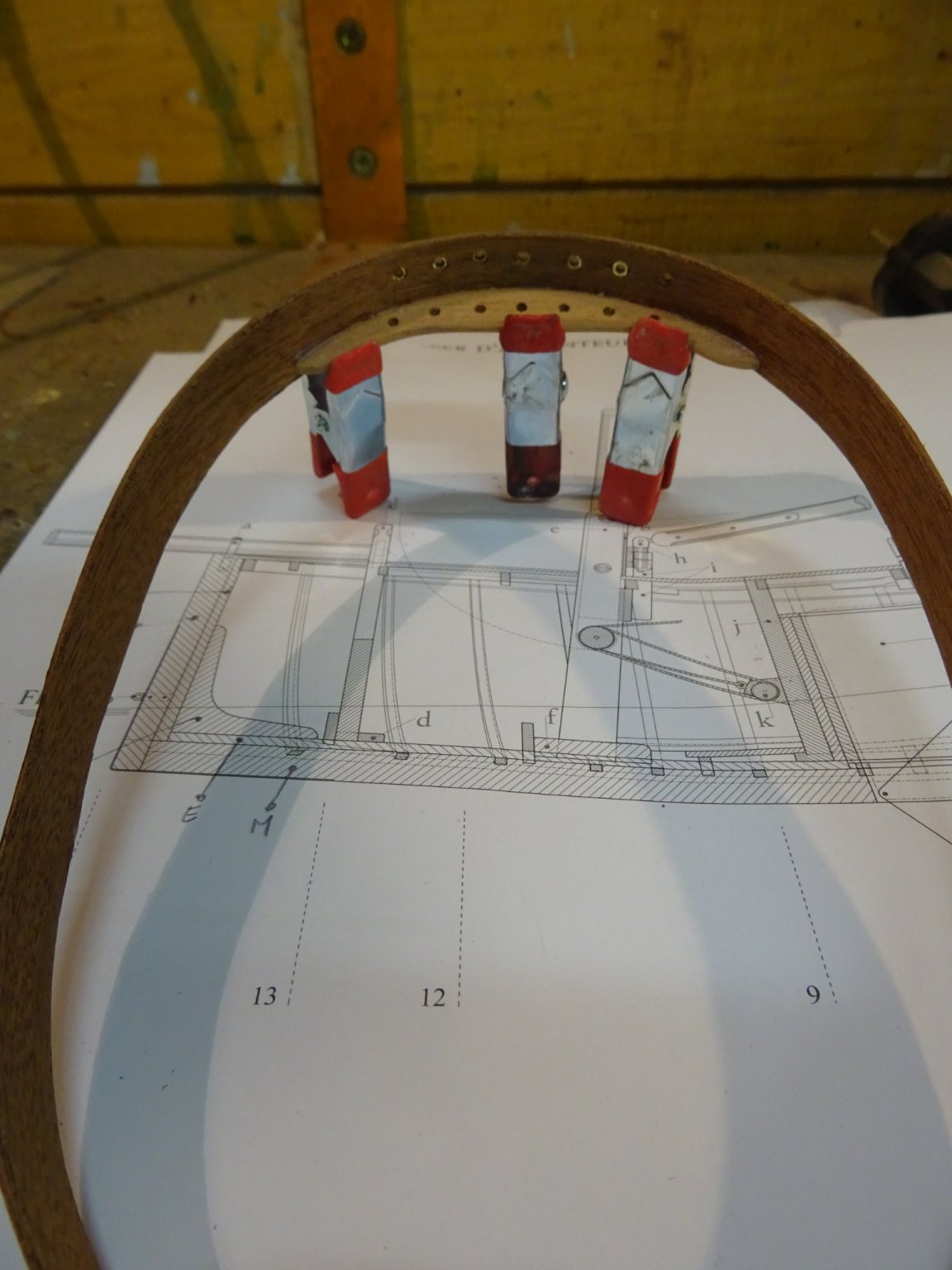
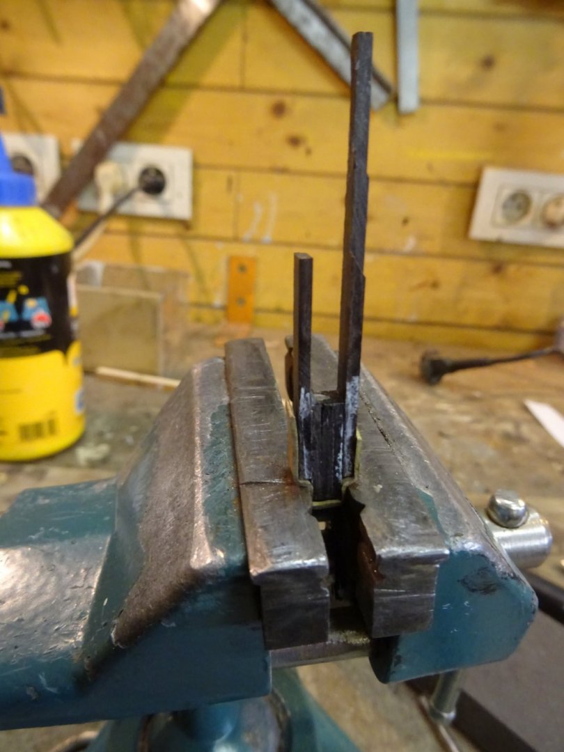
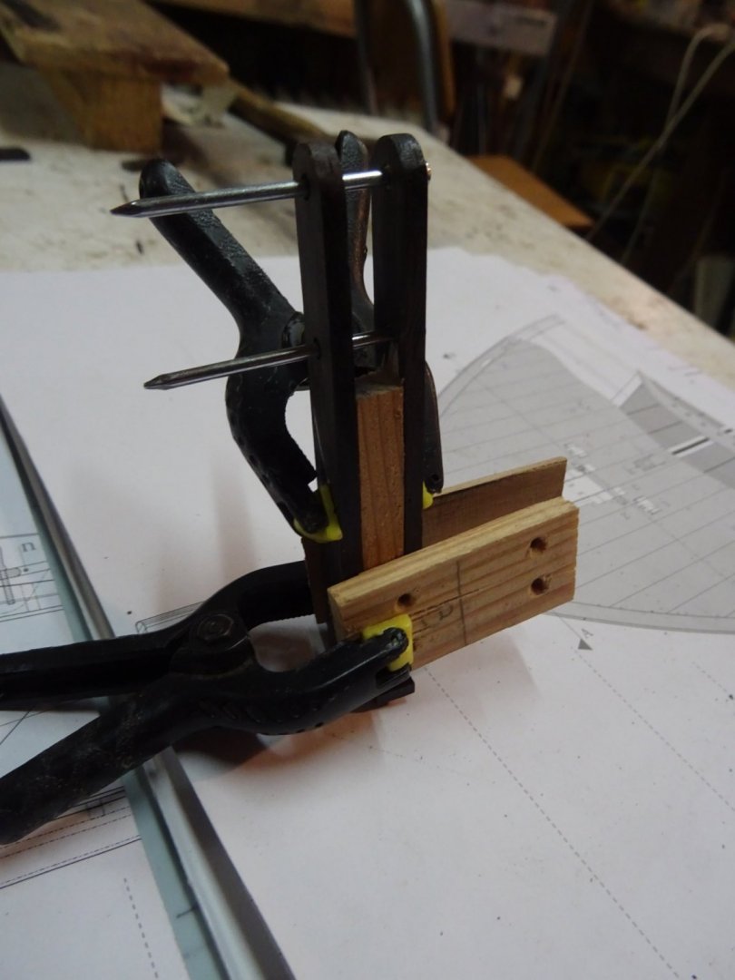
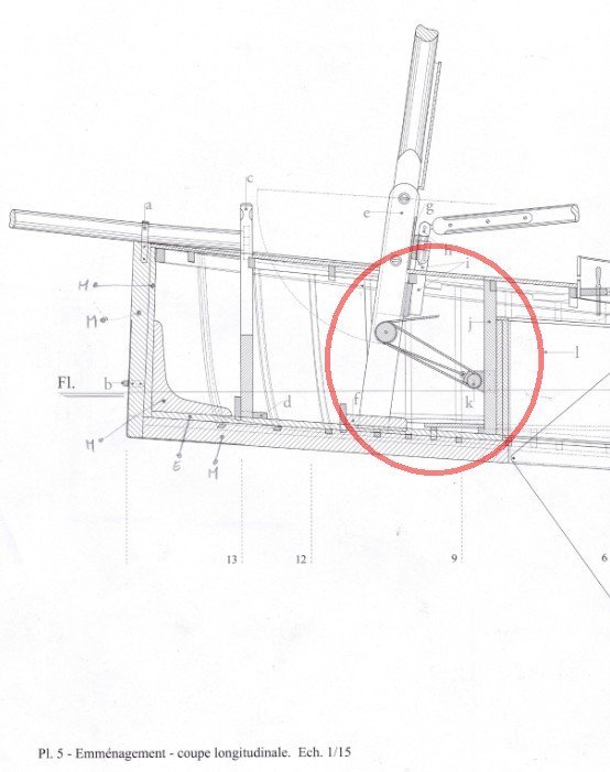
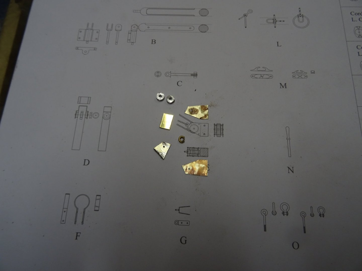
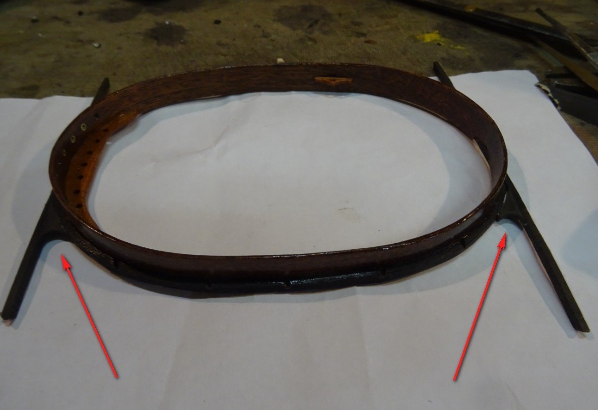
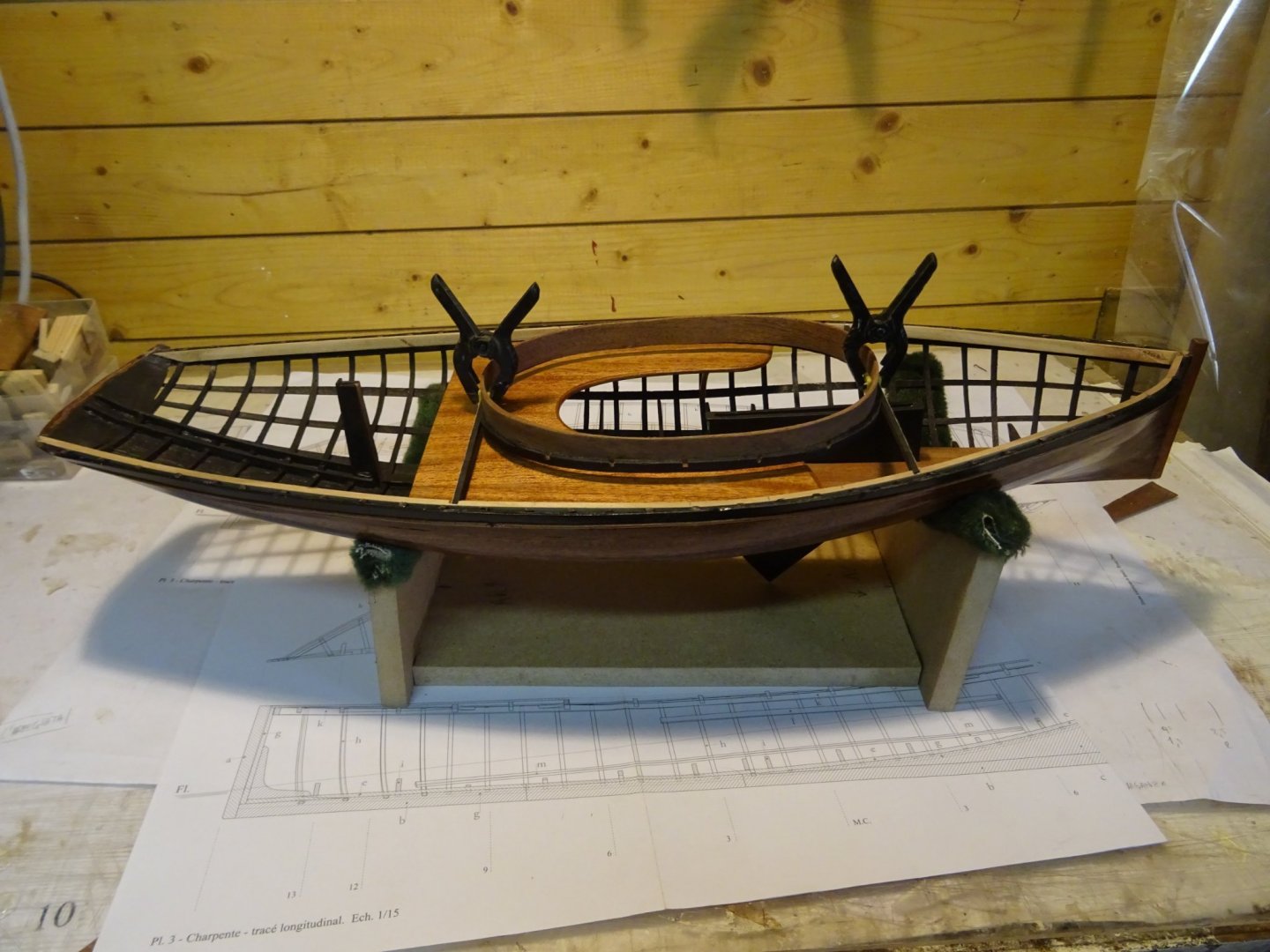
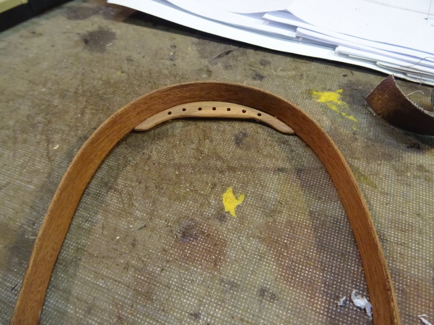
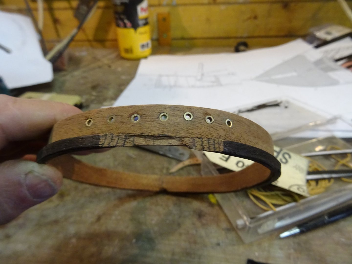
13. Mast tabernacle There are many bridges across the Seine, which is why it is useful that the mast of the clipper can be lowered and raised again by the crew. This is done by means of a hoist system with three sheaves in the mast base and two shaves at the bottom of the hull of the boat. Making the two sheaves for the fixed part. The different pieces. Assembling the pieces. Fitting it in the hull


- 153 replies
-
- 7
-
-
- Ancre
- Bruno Orsel
- (and 2 more)
-
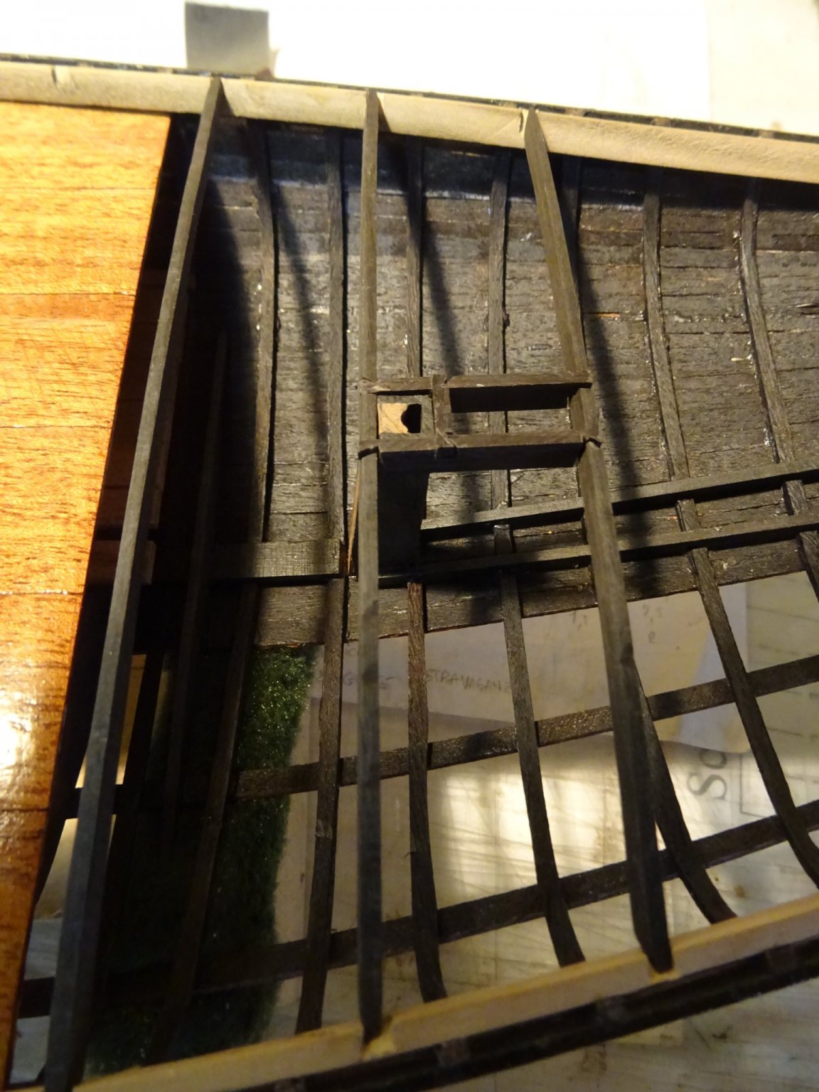
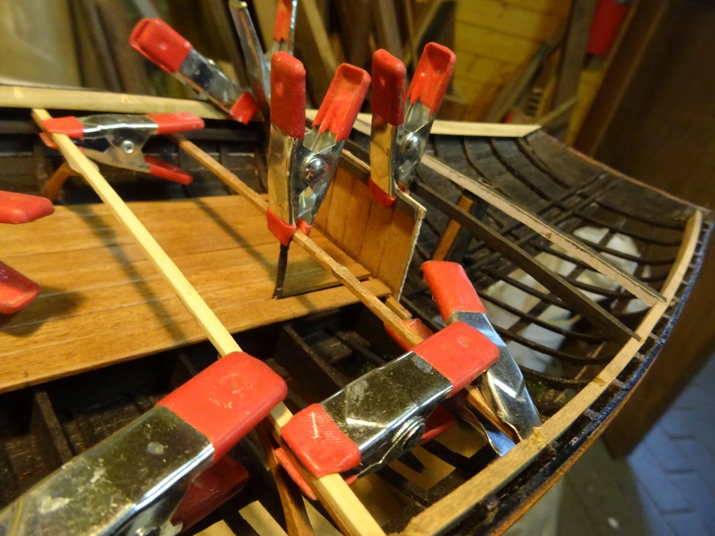
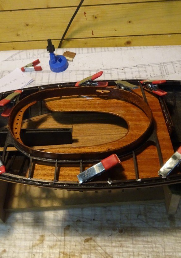
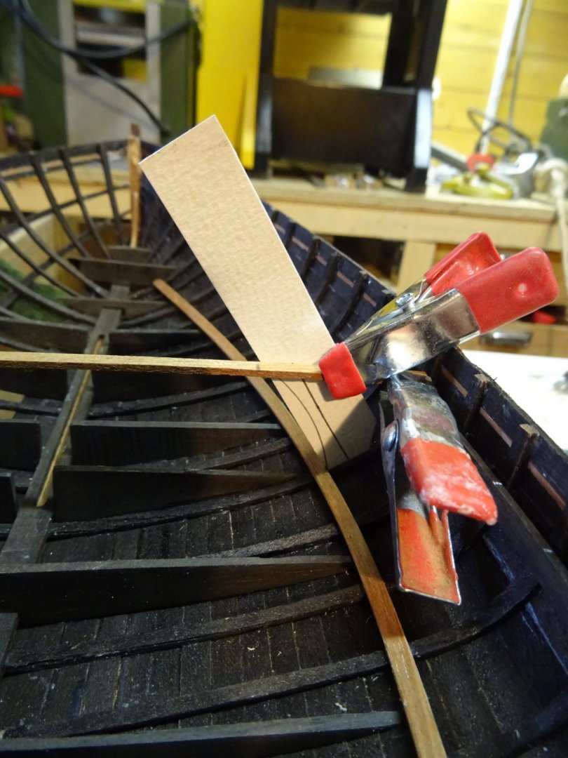
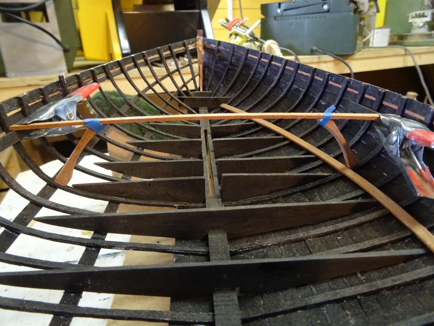
I start this week with finishing the coaming area. The attachment points of the coaming to the deck beams are reinforced with knees. At each side of the coaming come five short deck beams. The notches for the dove tails of the beams were already cut before the round beam clamp was glued to the coaming. The coaming with the port beams glued. Fitting the coaming on the model. I will wait to glue it definitively until all deck beams with accessories are made.
- 153 replies
-
- 9
-
-
- Ancre
- Bruno Orsel
- (and 2 more)
-
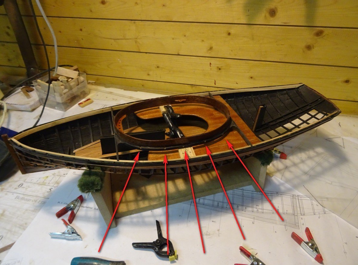
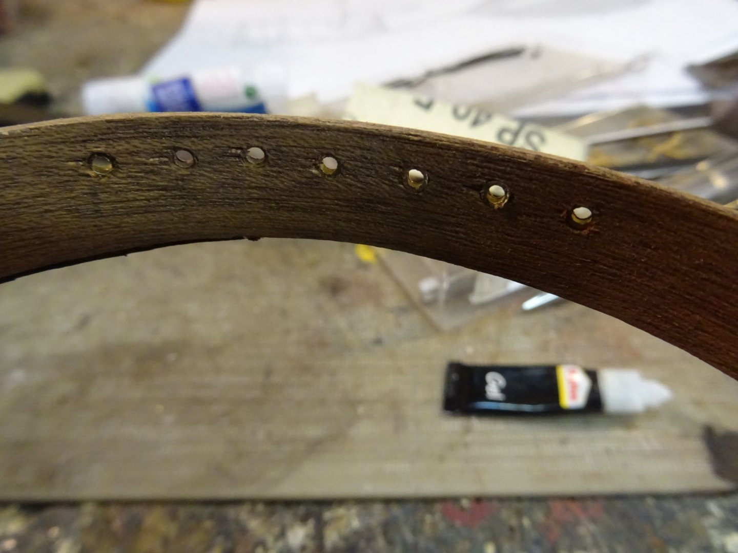
Fitting the coaming. In the beam round the coaming the dove tails notches for the deck beams are already made. At the front of the coaming is a shelf that serves as a pin rail. Making the pin rail. In front of the pin rails there are passage holes through the coaming for the halyards and sheet. They are protected against scouring with a piece of brass pipe. Gluing the pin rail. ...and re-fitting the coaming. Now the coaming can be varnished. Note that there are also two extra pin holders in the coaming. In the photo you can see the starboard one. Thank you very much for reading this log, for your likes and for your encouraging reactions. Till next week!


- 153 replies
-
- 10
-
-
- Ancre
- Bruno Orsel
- (and 2 more)
-
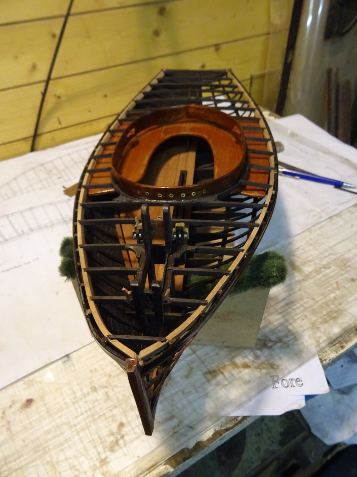
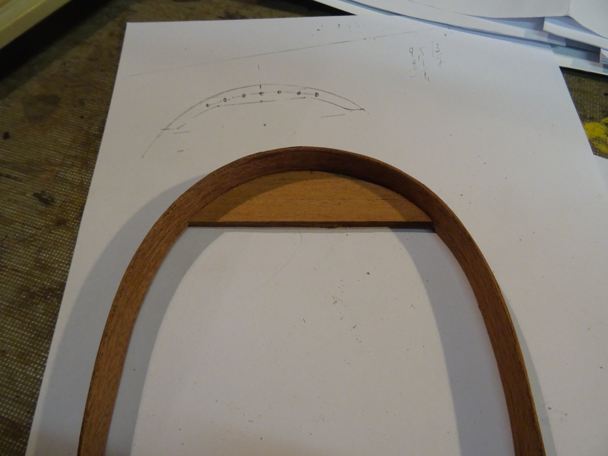
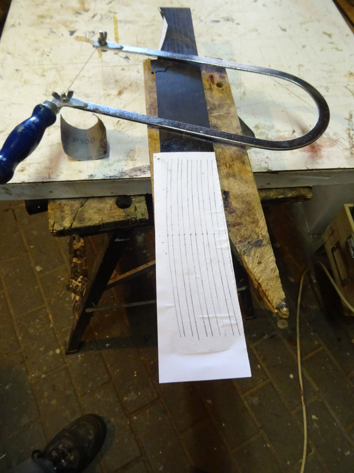
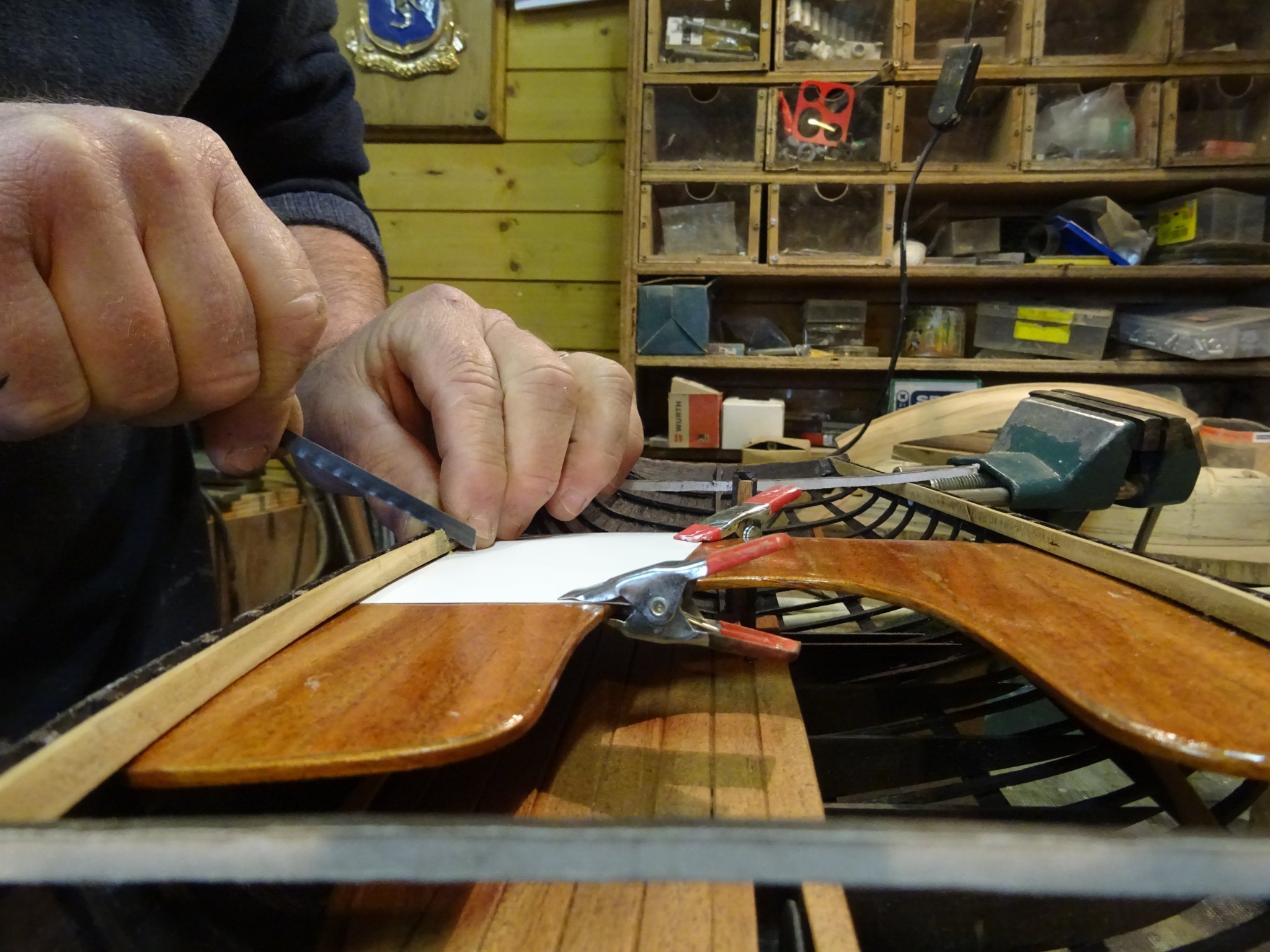
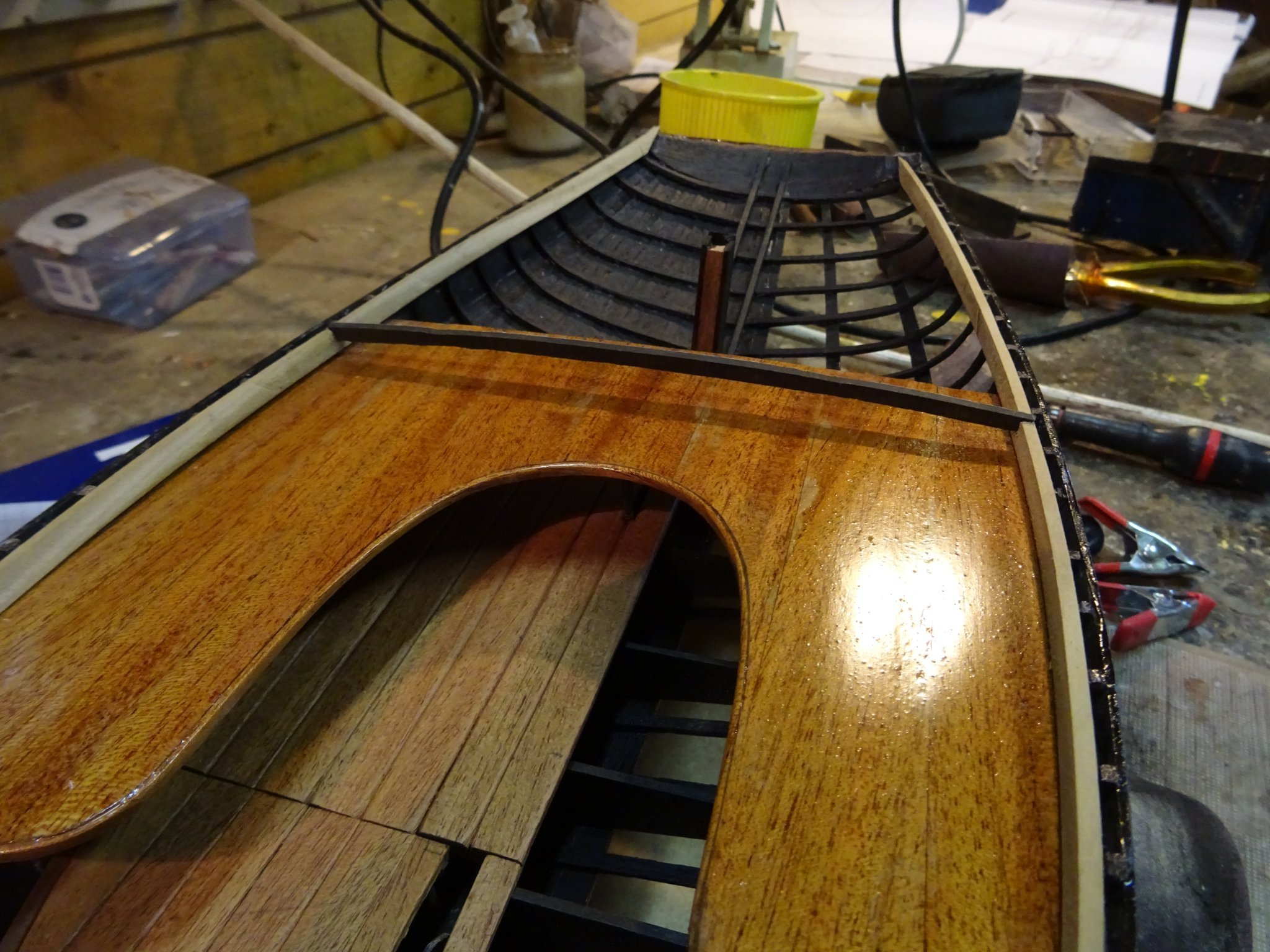
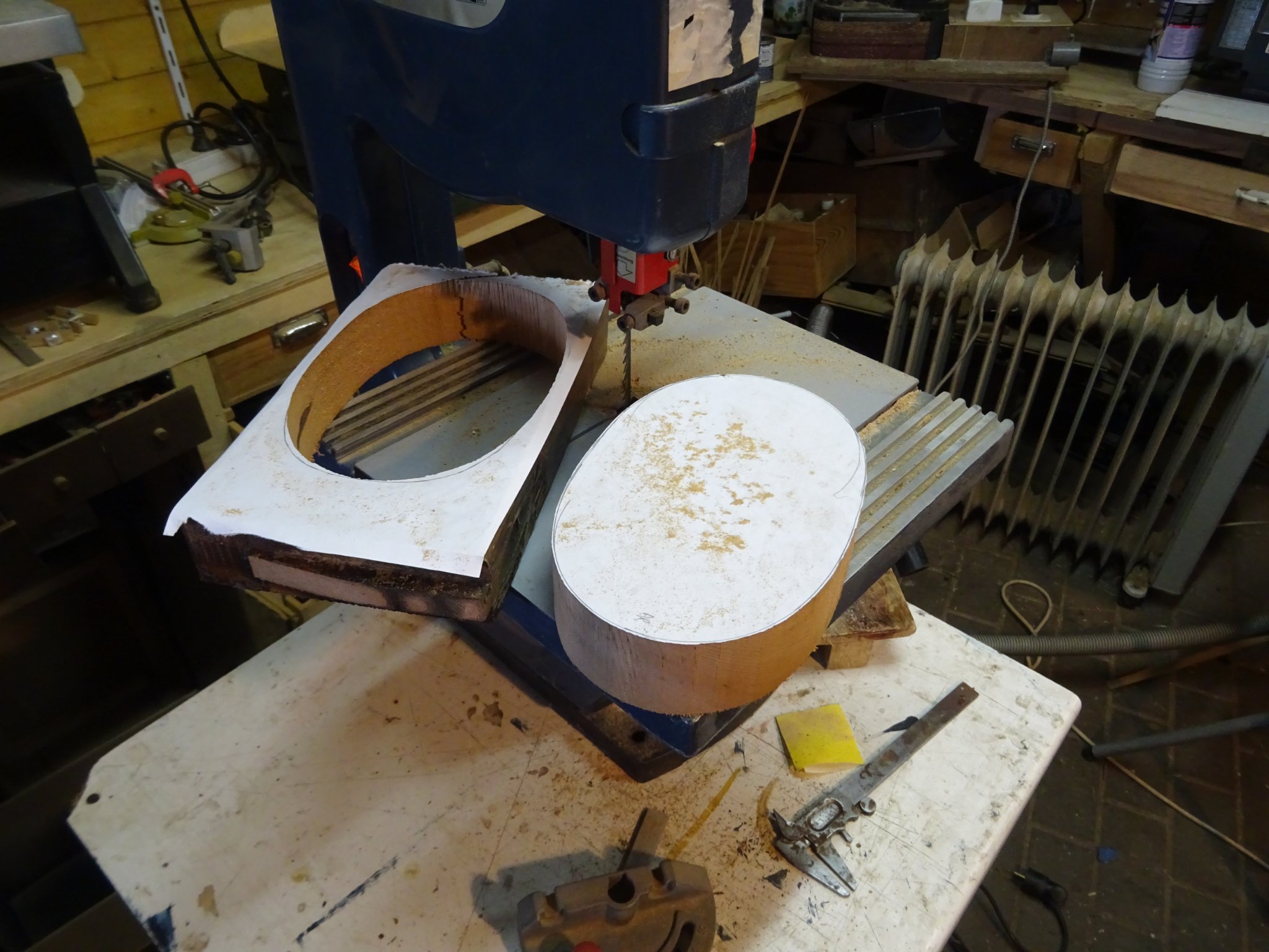
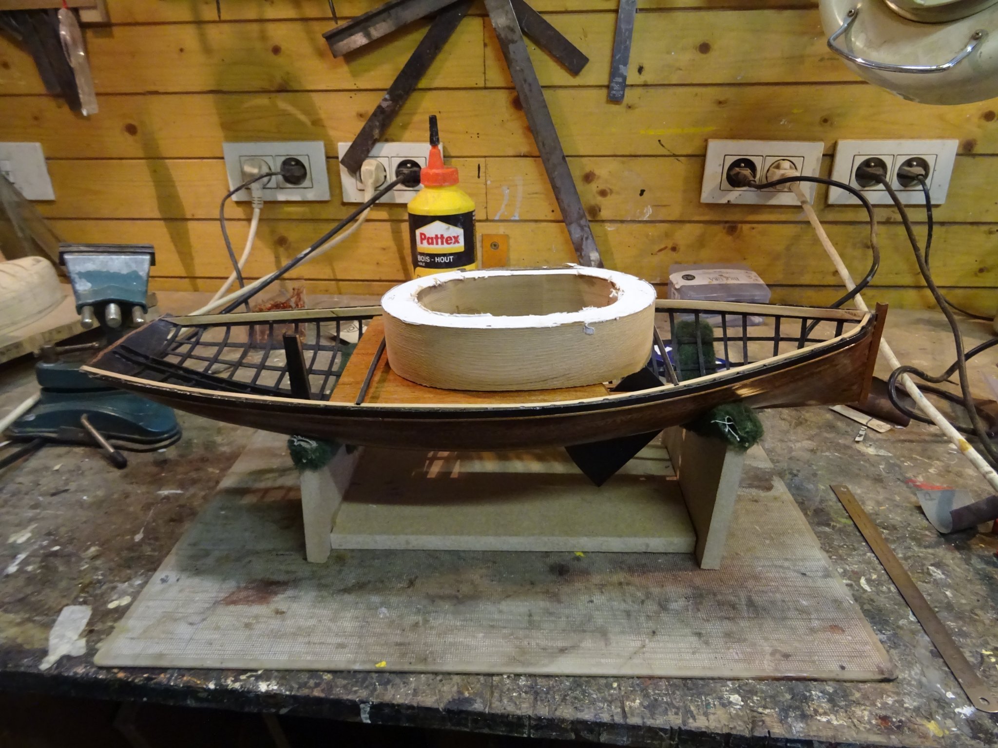
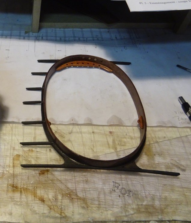
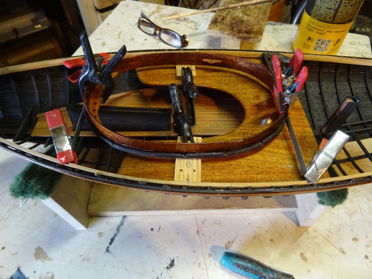
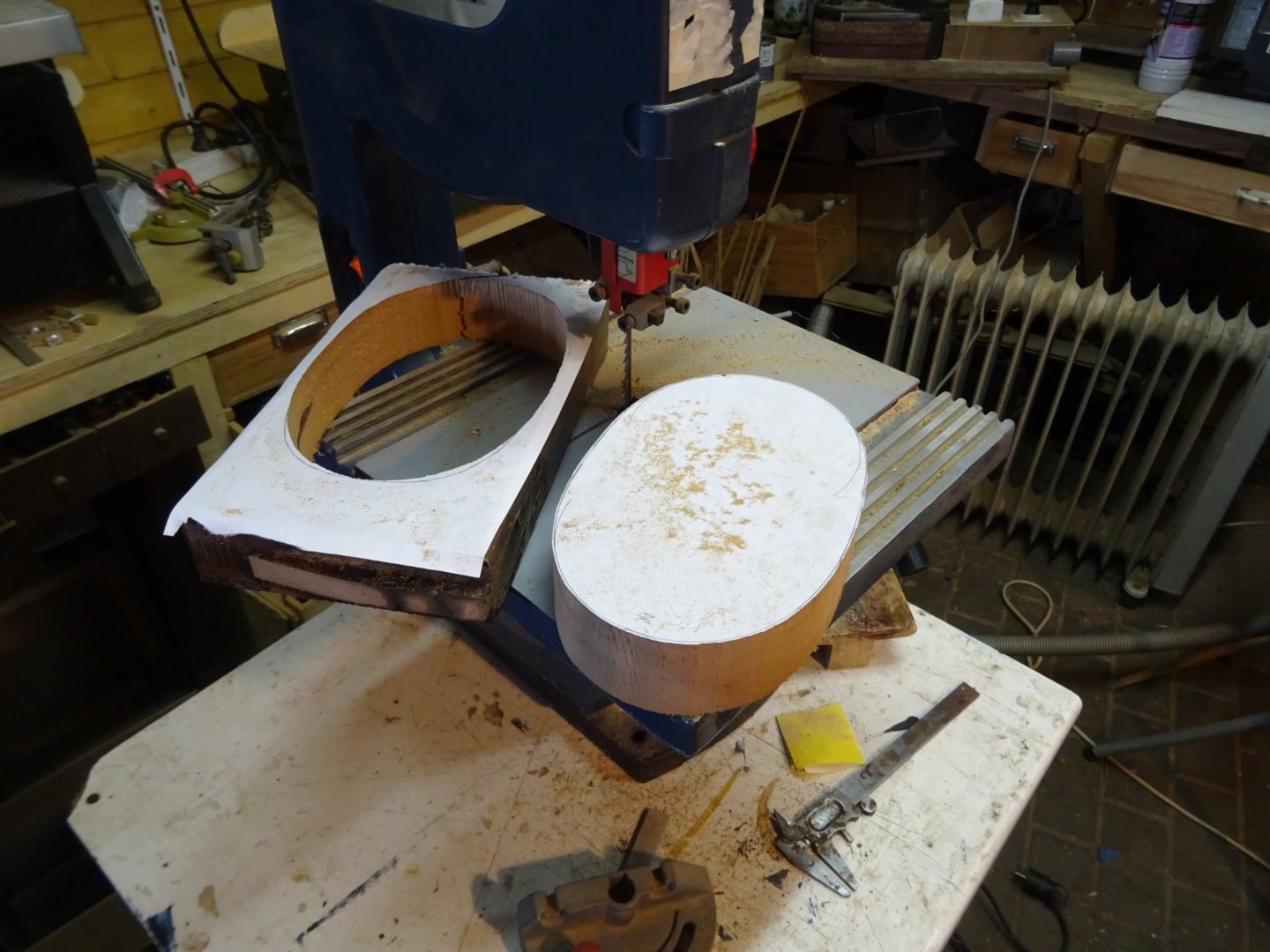
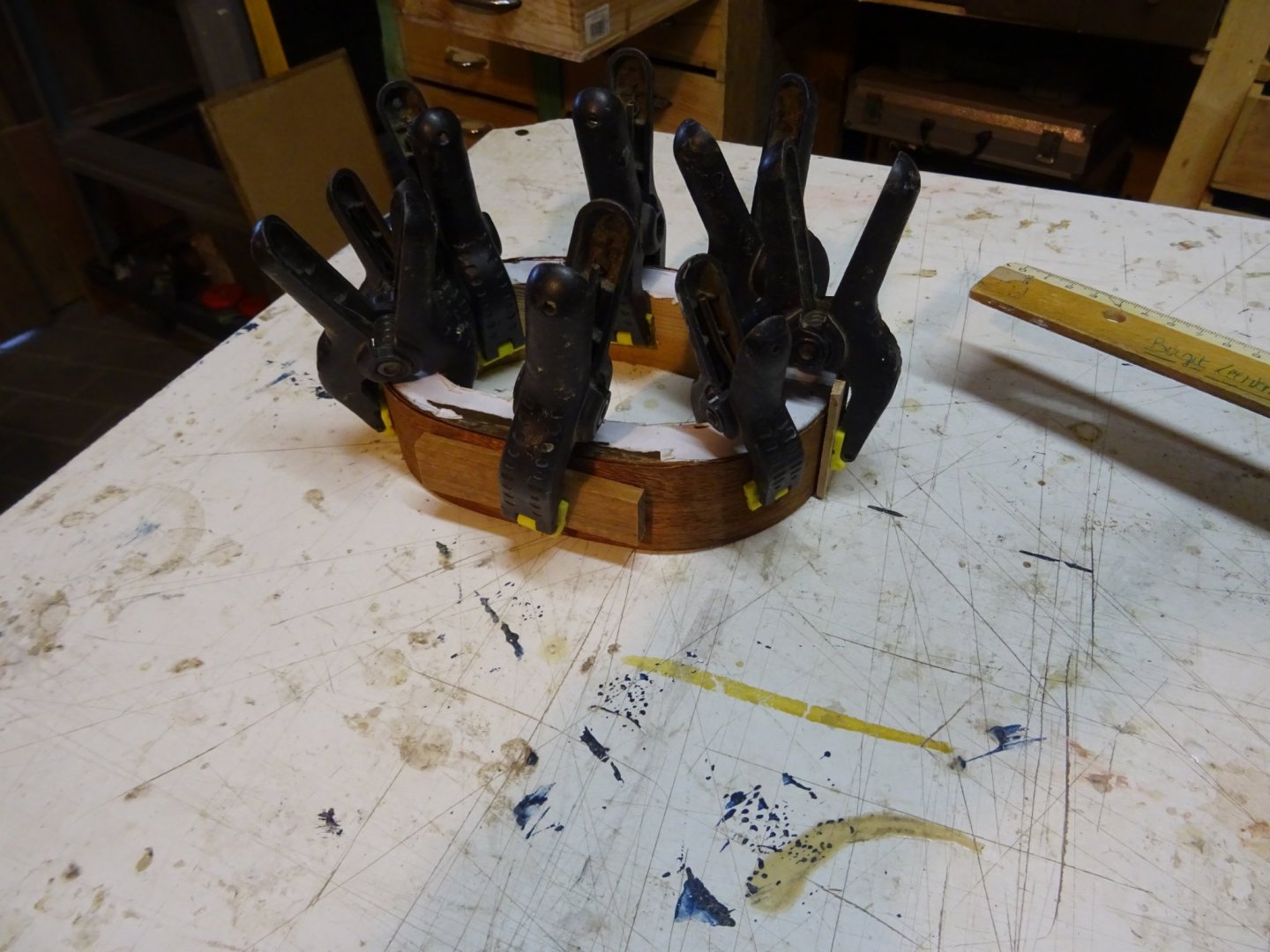
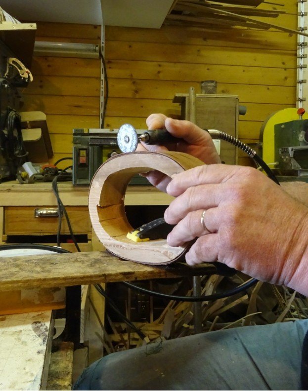
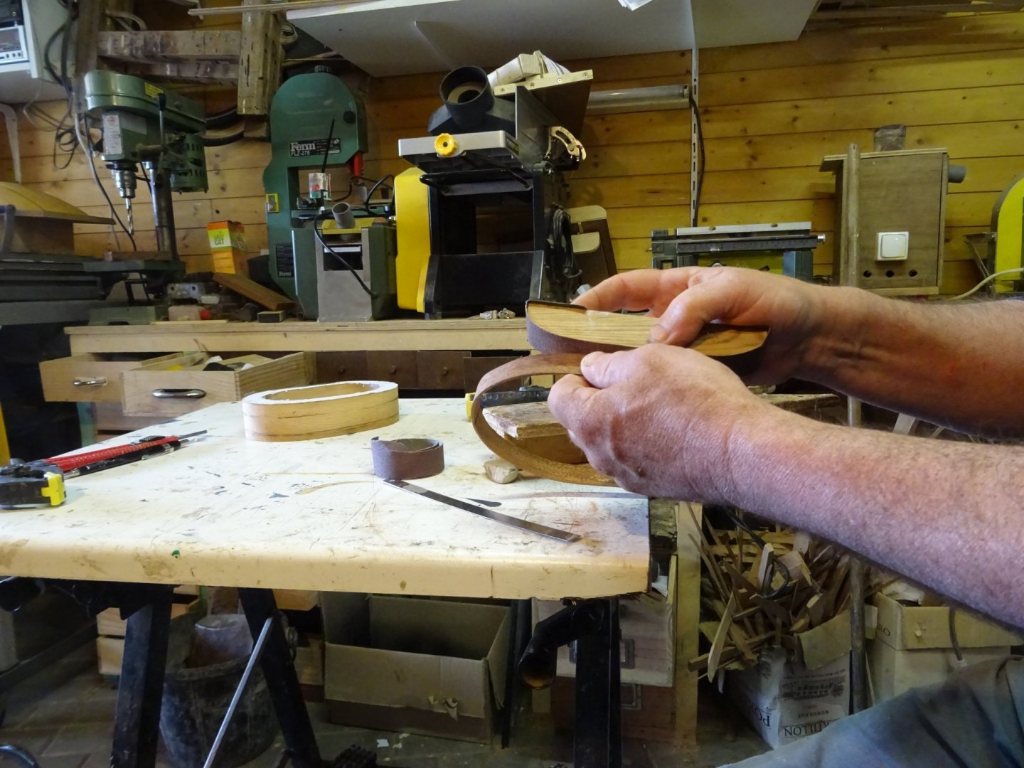
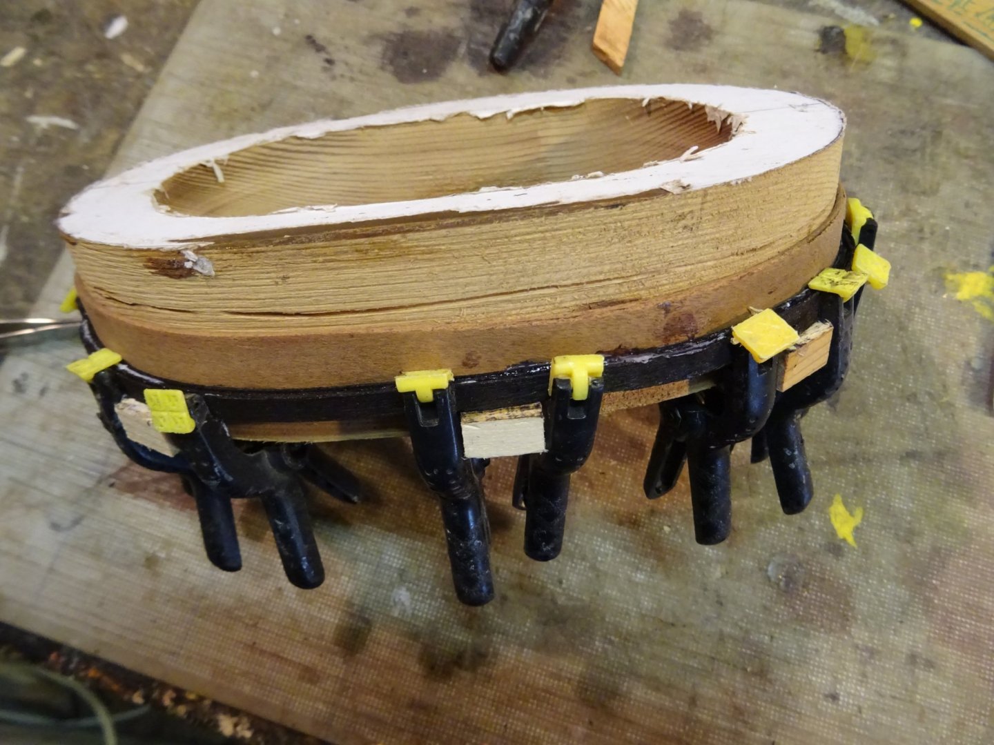
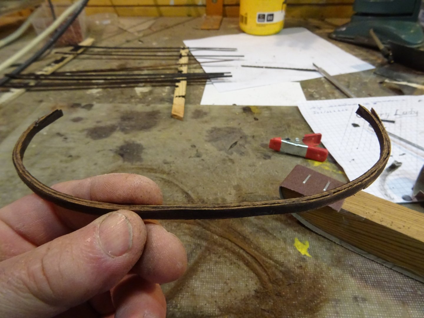
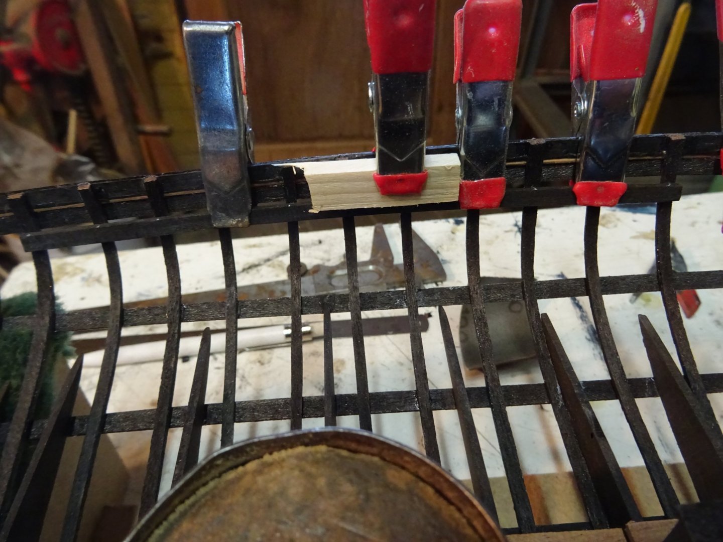
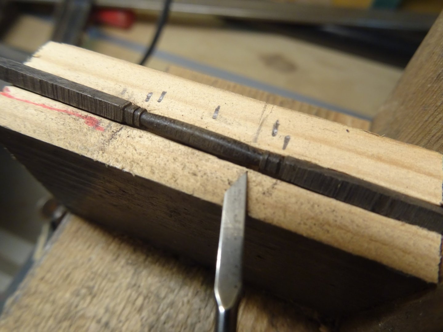
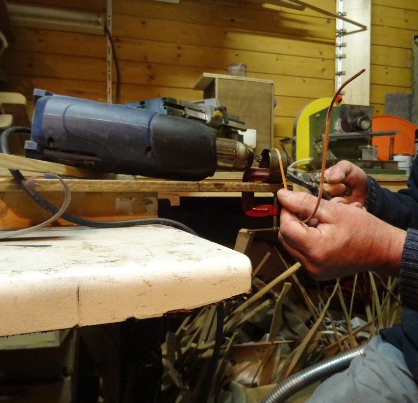
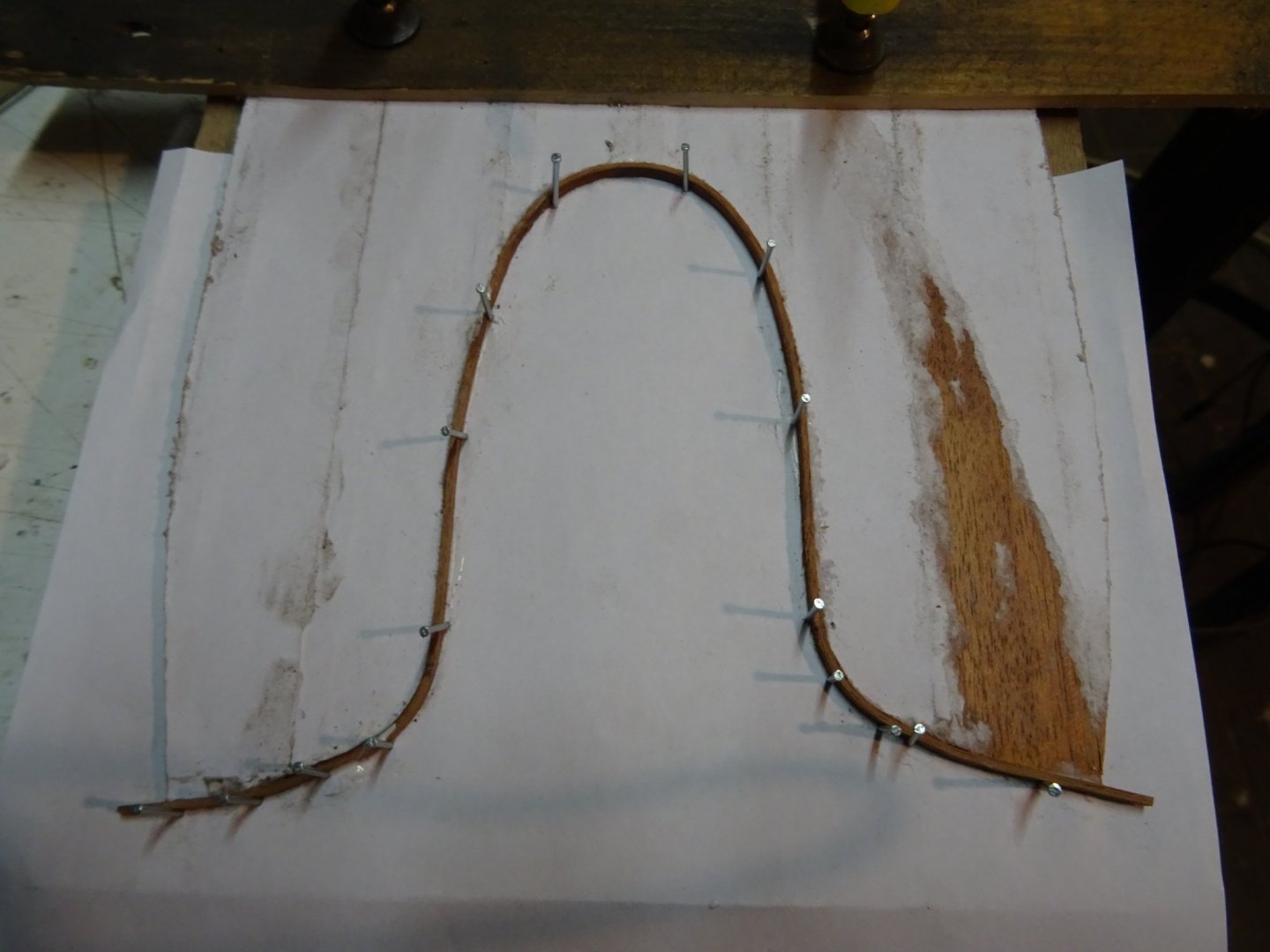
12. Cockpit coaming. The cockpit coaming has to be integrated in the deck beams. Before making it I will lay first the two adjacent deck beams. Therefore I have to glue the beam clamps first. I learned from my experience with the wales that bent ebony transmits great pressure to the model (post 43), so I do not make the deck clamp from ebony, but from cherry. I will stain it black later. I saw the deck beams out of 3 mm thick ebony. They are sawn manually with the help of a paper template glued on the wood. The deck beams sit in notches in the beam clamps. The notches are sawn with a small metal saw blade. a piece of cardboard protects the thwart. The two deck beams bounding the cockpit coaming. The cockpit coaming has an oval shape. It will be made by laminating three layers of mahogany veneer. I saw the laminating mold of a piece of waste wood. Presenting the mold on the model. Gluing the three layers veneer. When the glue is dry I saw out the coaming... ... and I sand the edges. Round the bottom side of the cockpit coaming lays a round deck beam. It is also made by laminating four strips of veneer round the coaming. The beam will consist of two half rings. Here it is like it comes off the mold; it still has to be sanded, sawn to size and re-stained in black.


- 153 replies
-
- 7
-
-
- Ancre
- Bruno Orsel
- (and 2 more)
-
Making sails! I was afraid of it for a long time. But as with most things, once you start doing it, you start to like it. I am full of admiration for your Singer sewing machine, it will be quite an adventure to get it up and running again.
- 756 replies
-
- 3
-
-
- galleon
- golden hind
- (and 2 more)
-
Good job, tom. I also bought the capstan monograph. I haven't had time to get started on it yet. I am already enjoying your project.
-
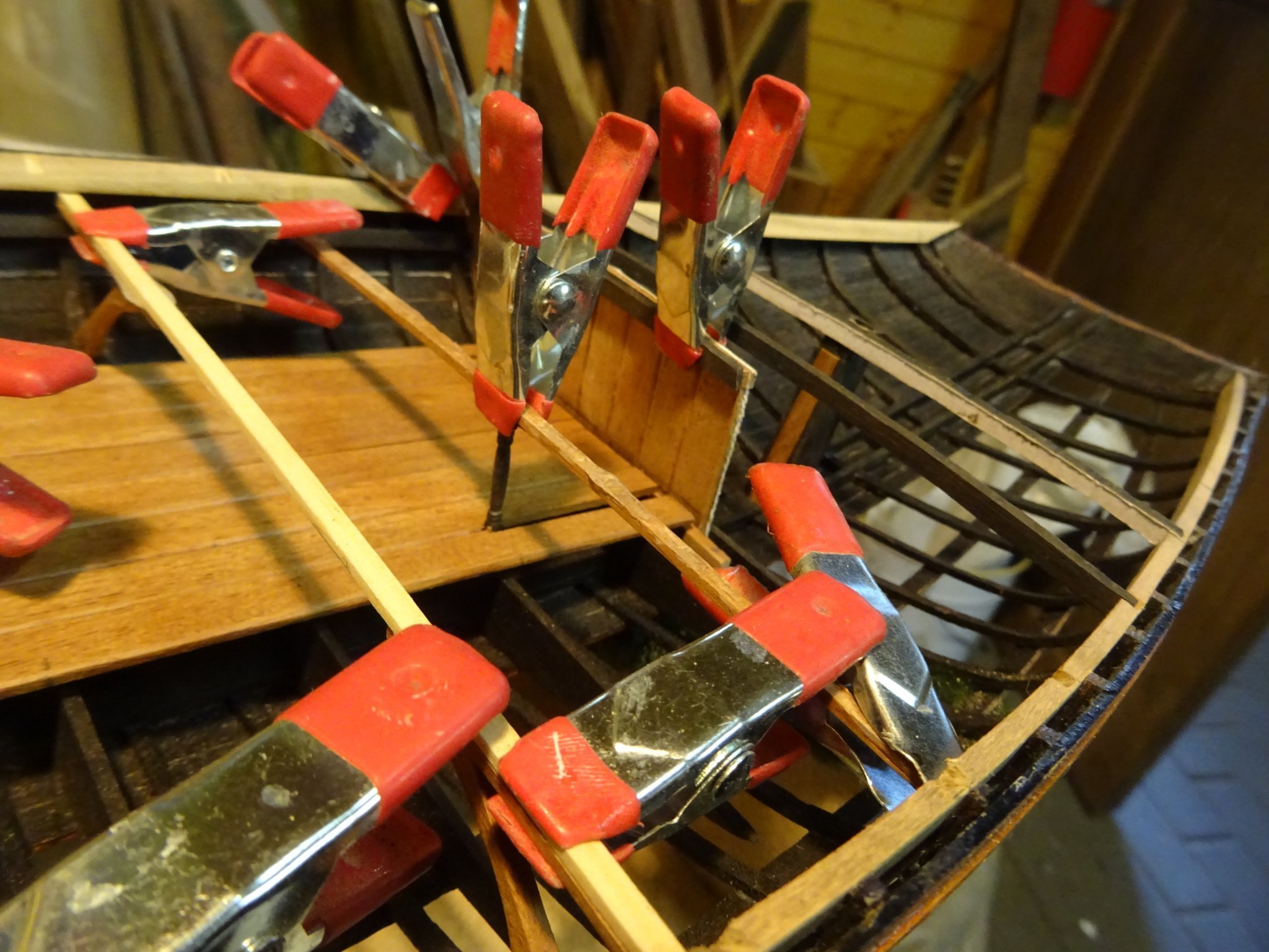
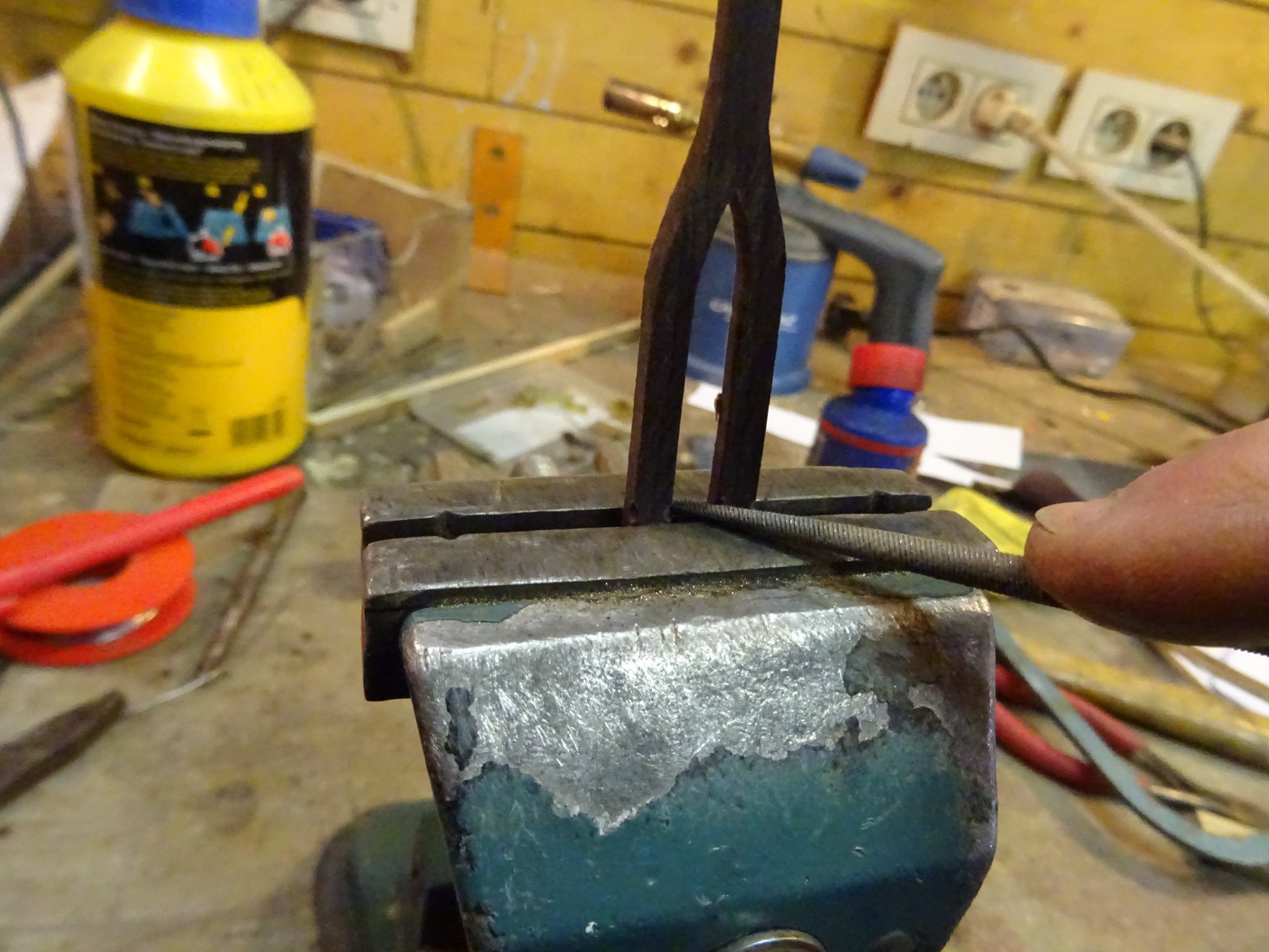
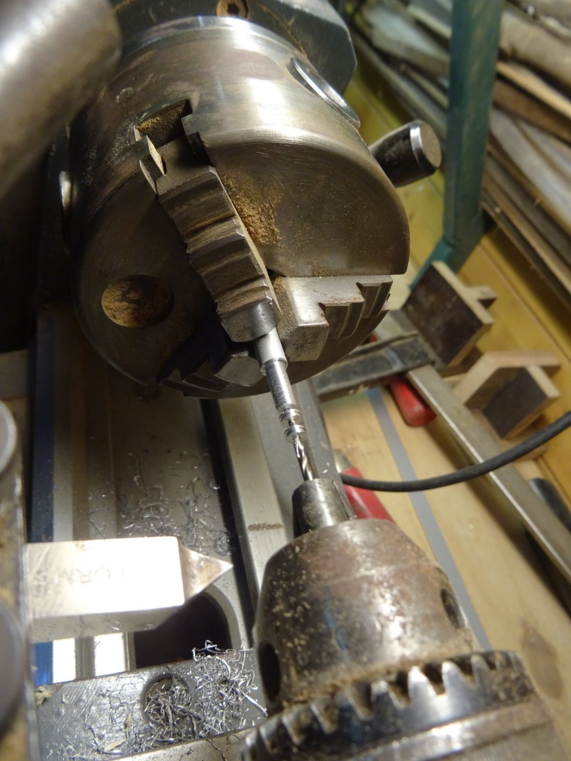
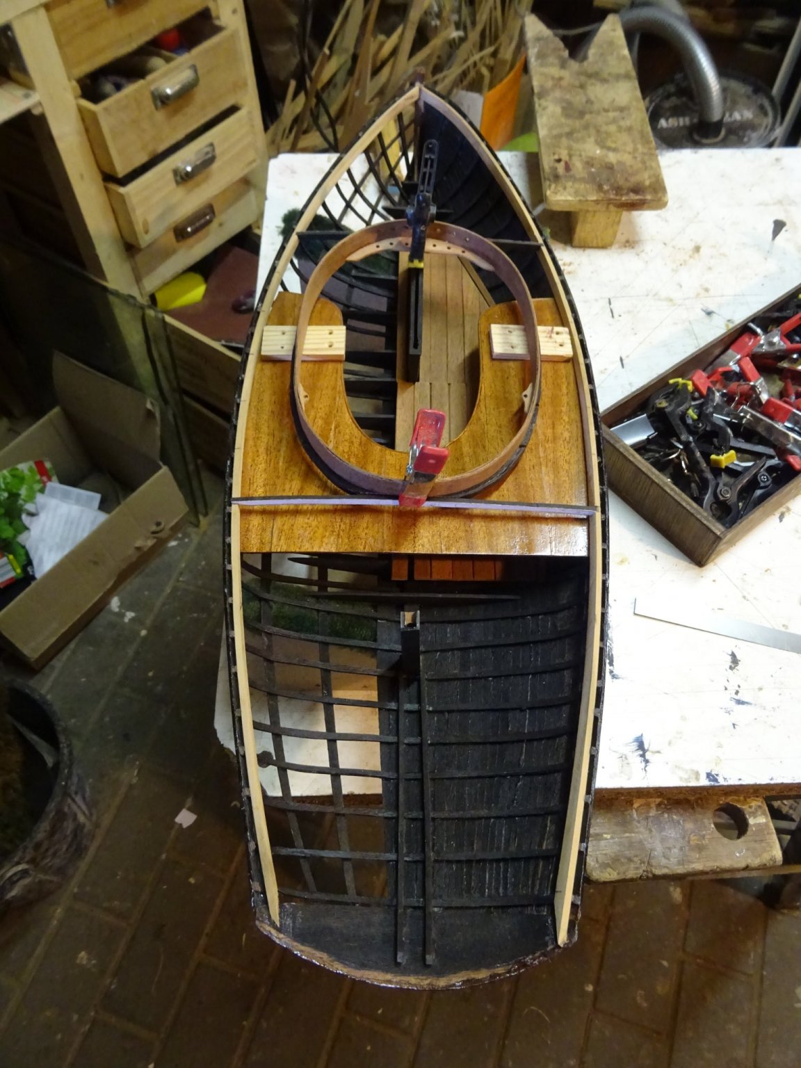
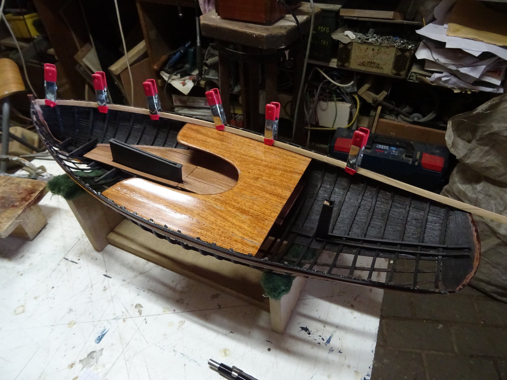
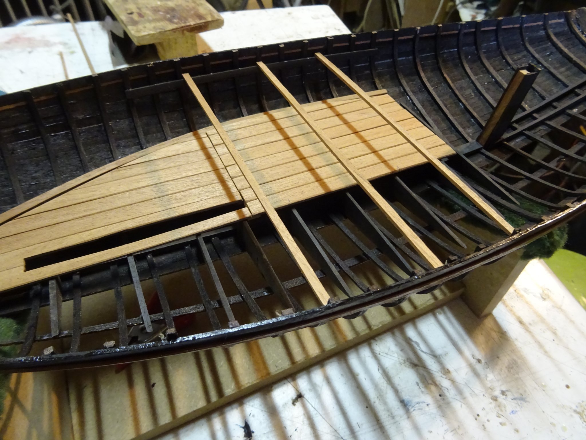
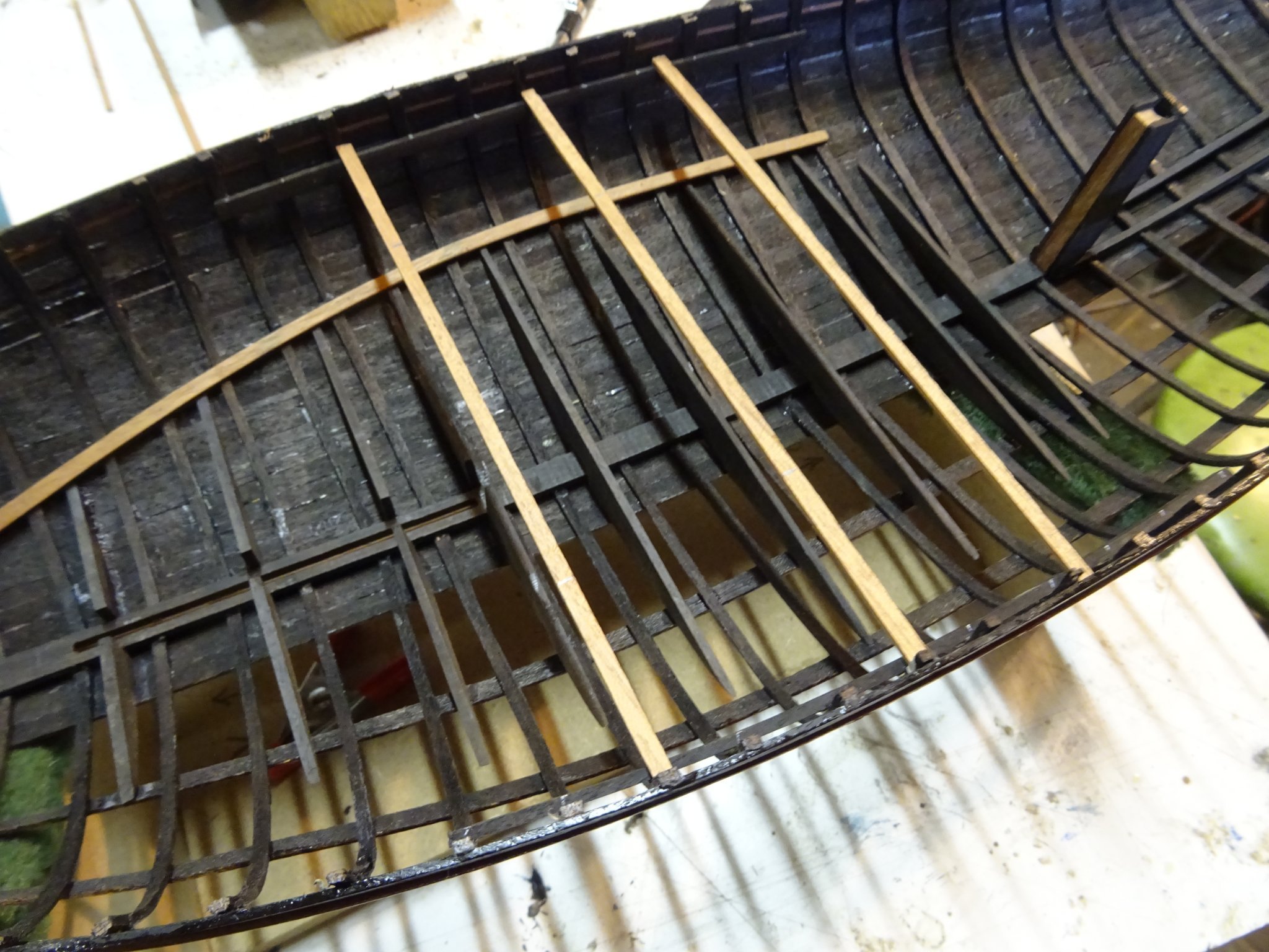
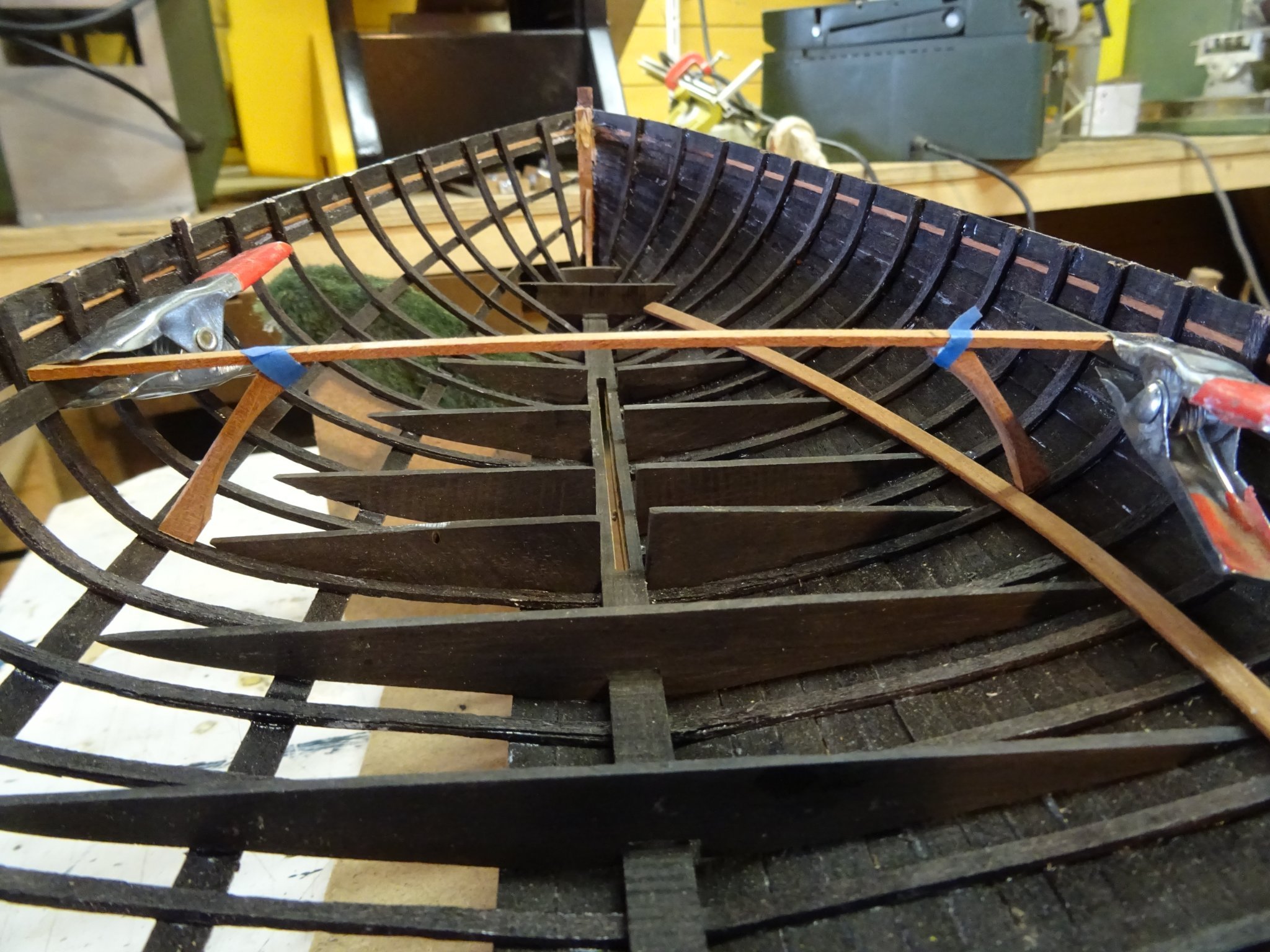
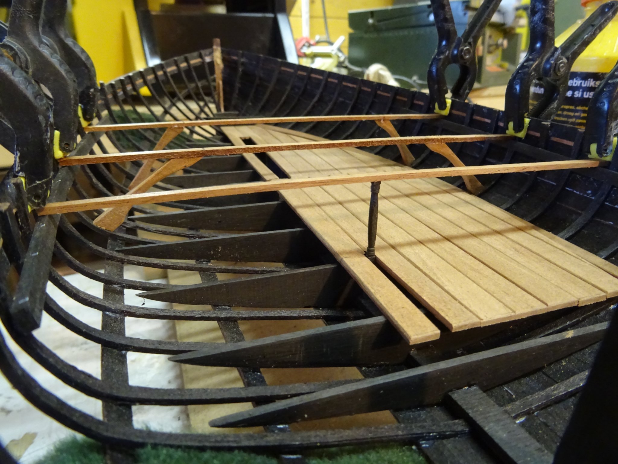
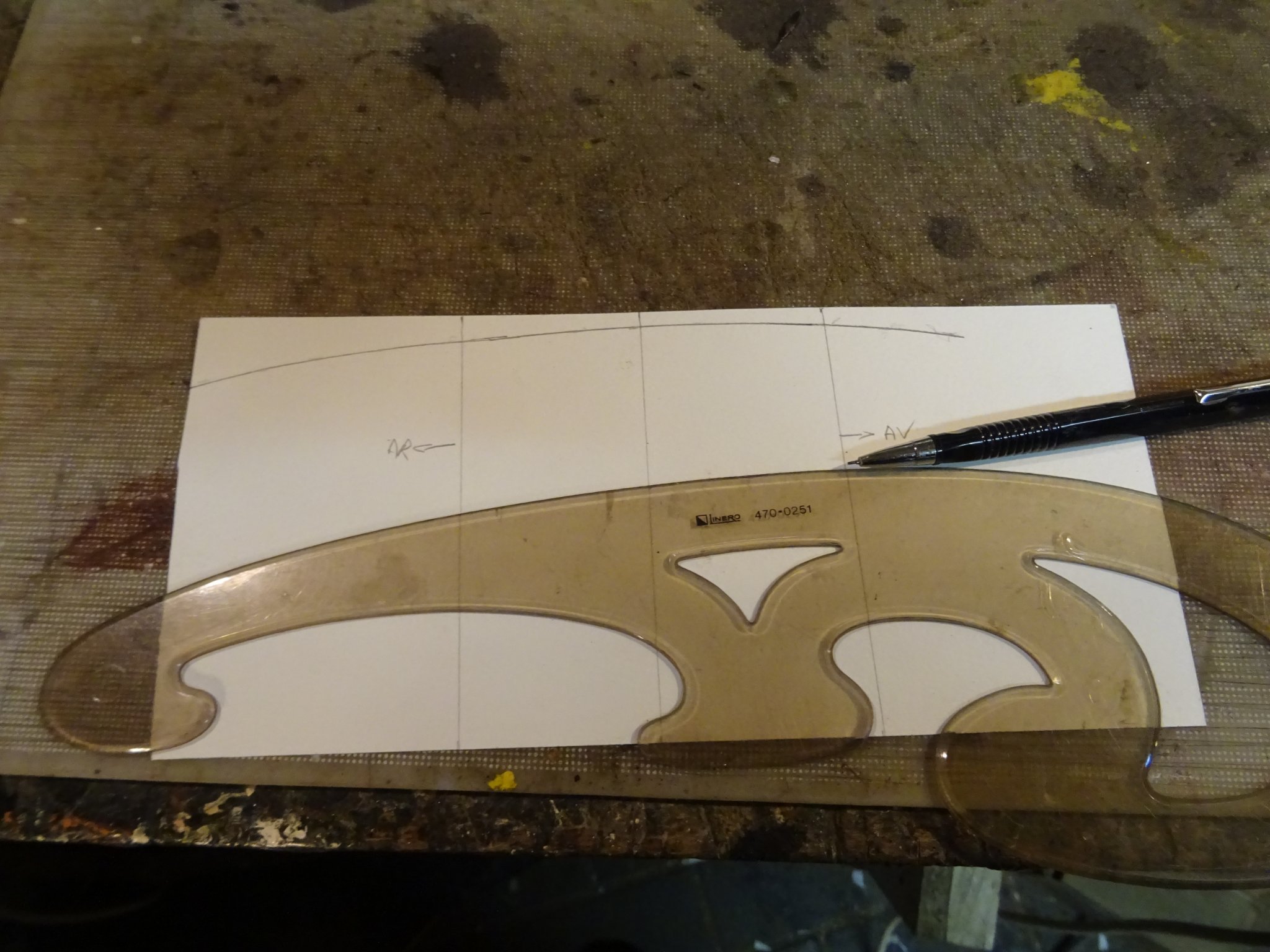
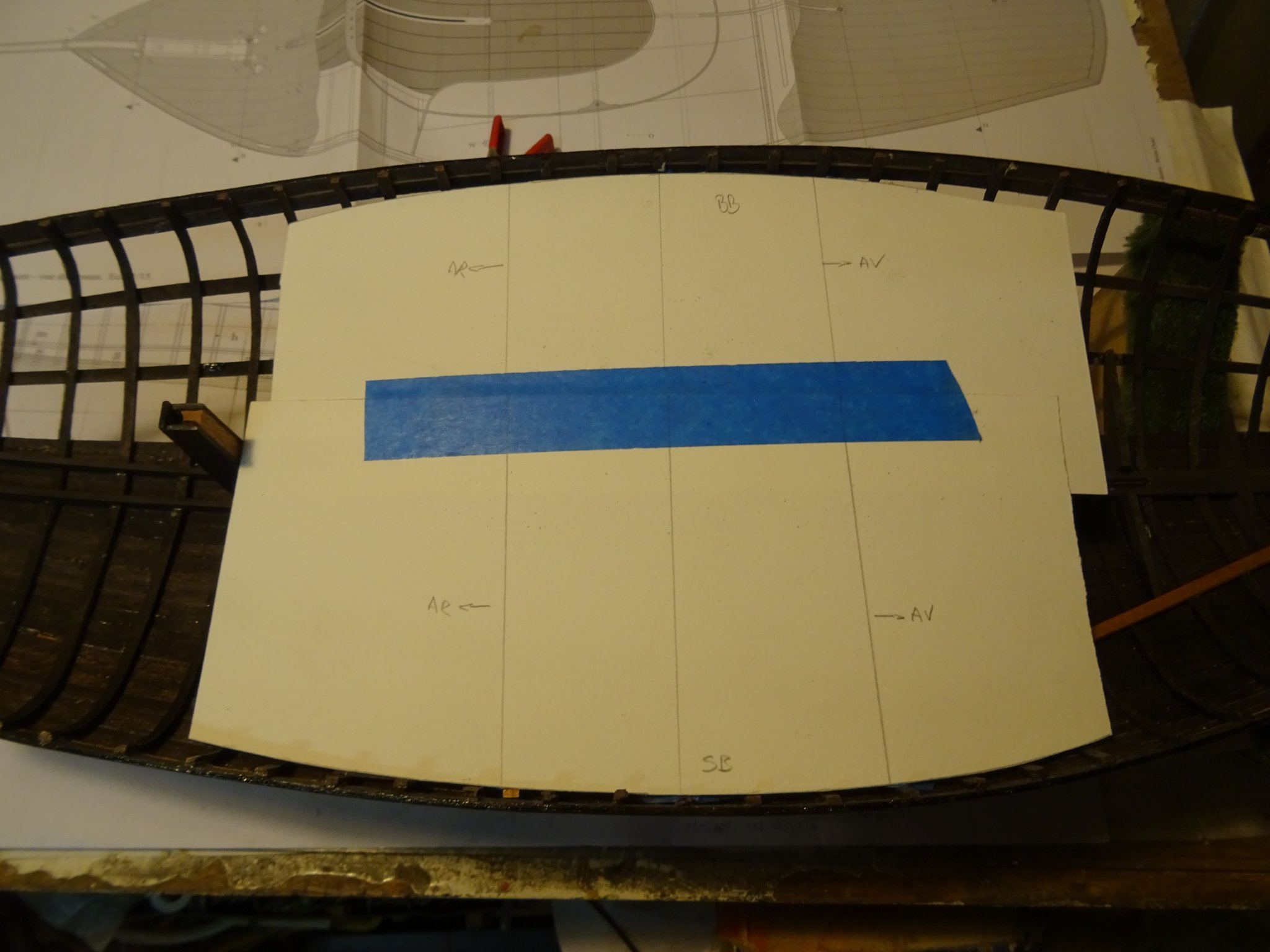
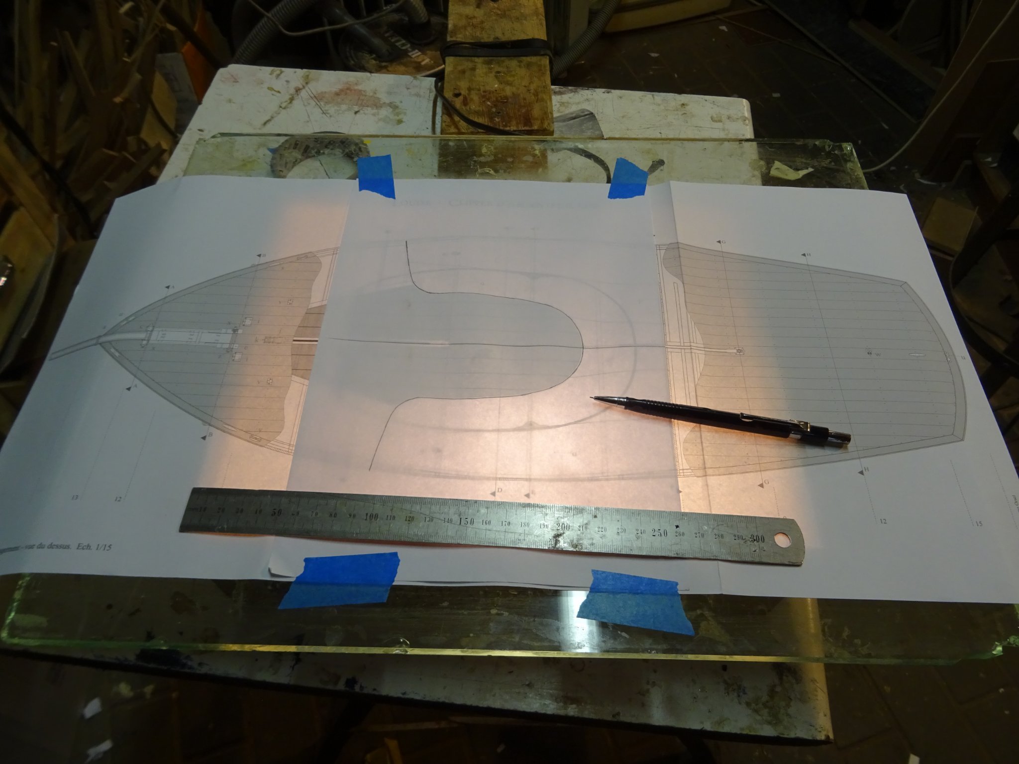
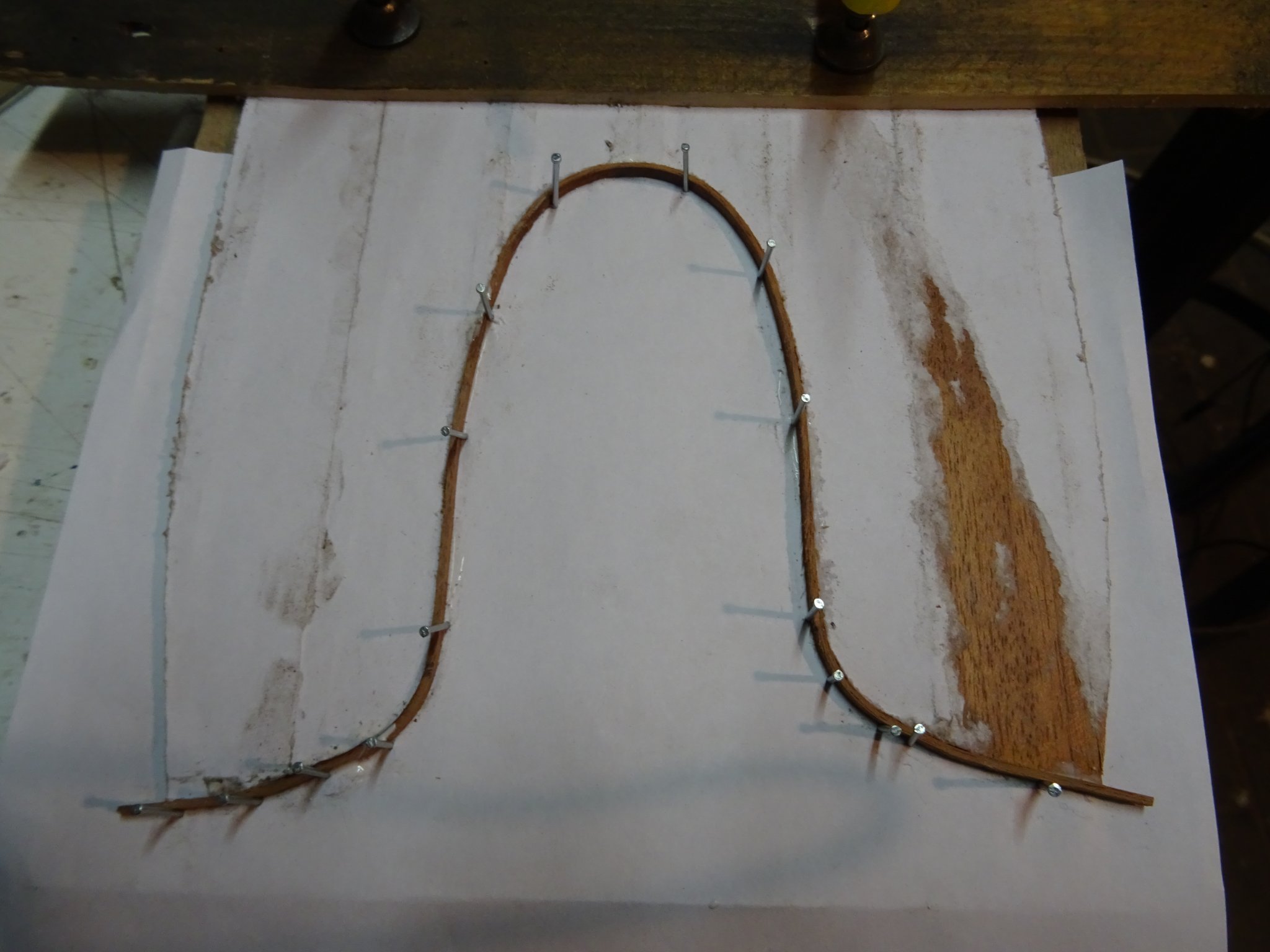
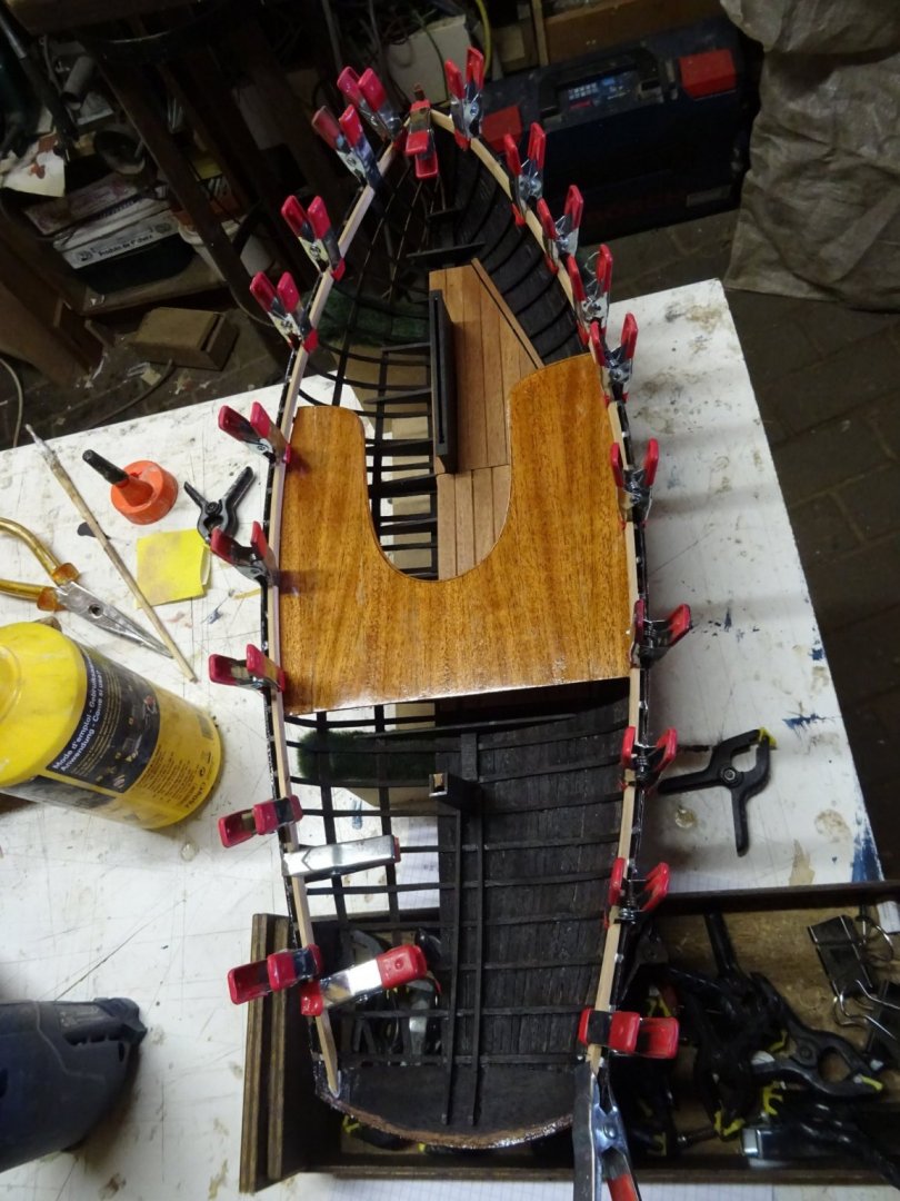
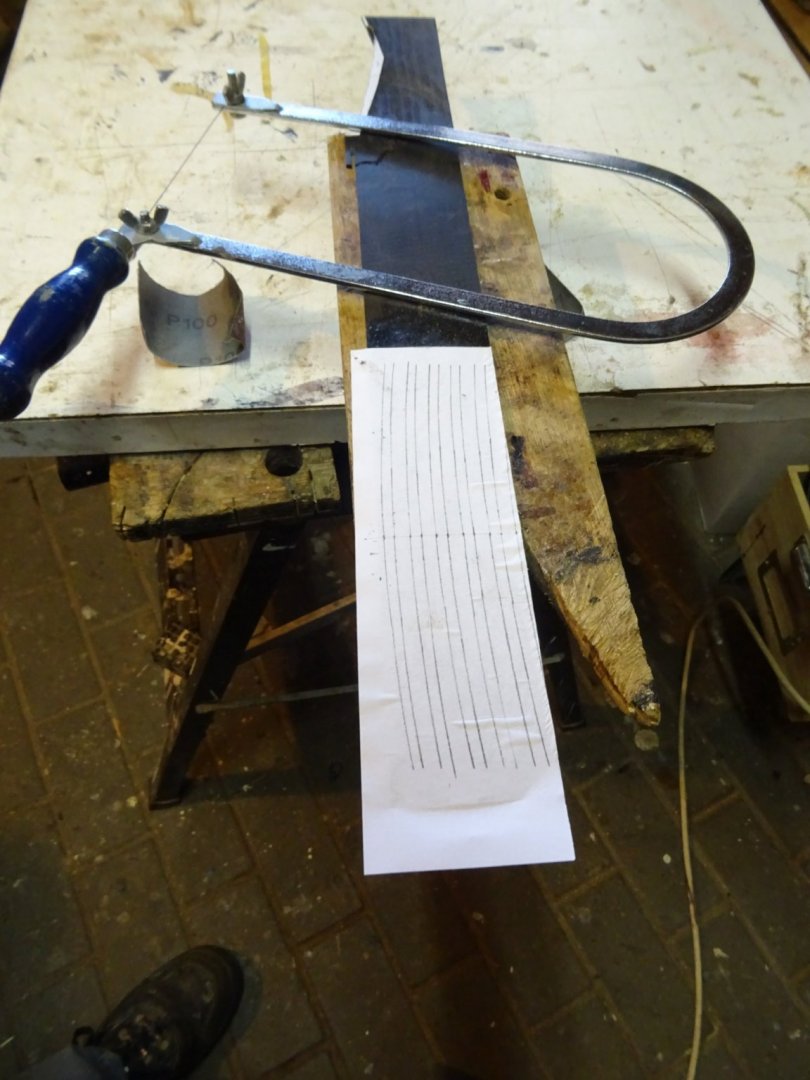
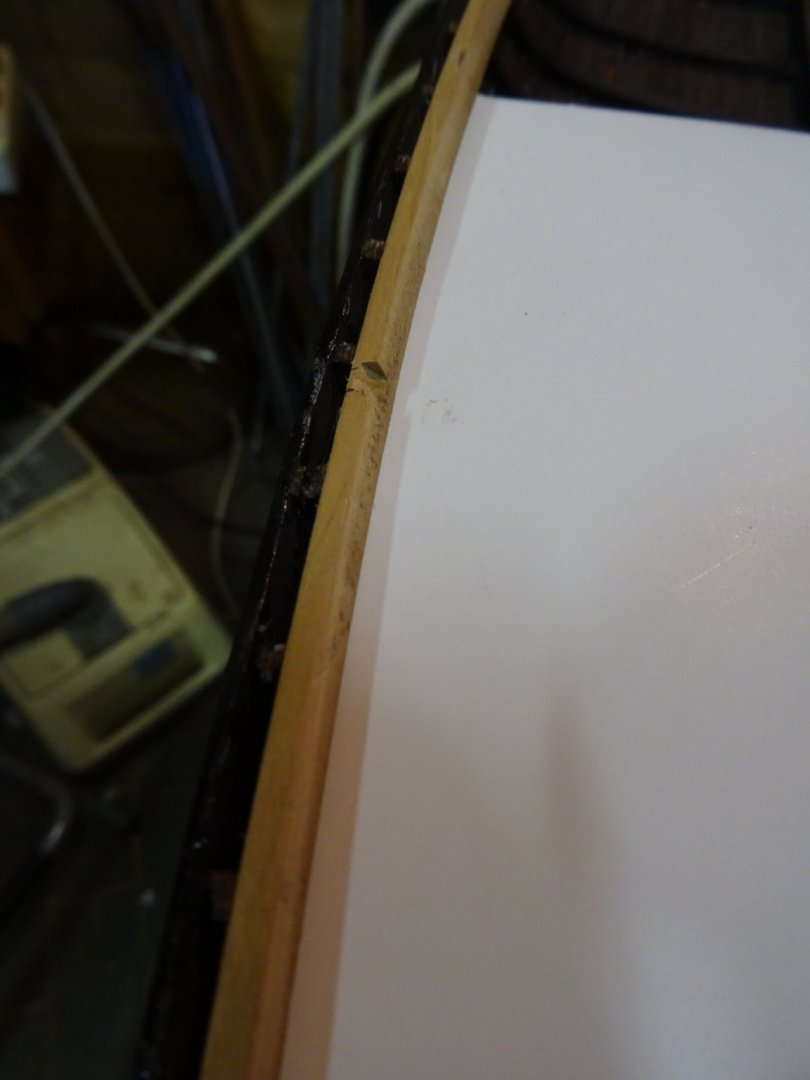
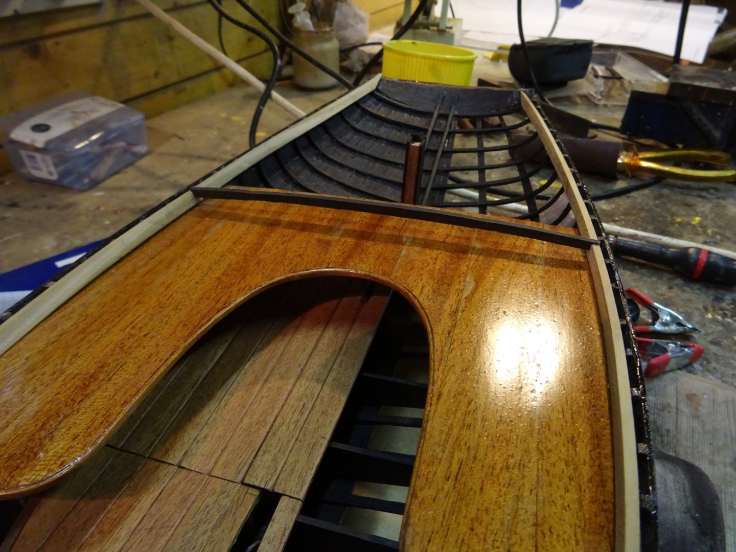
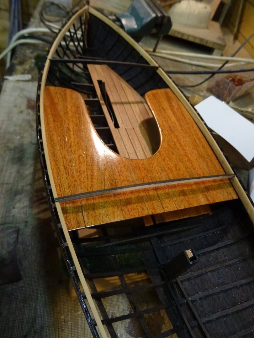
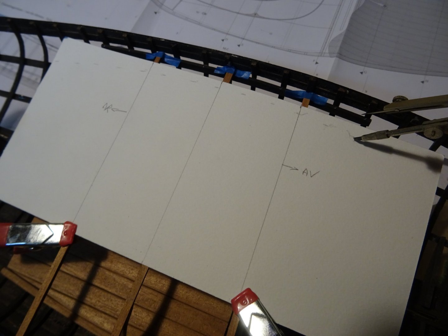
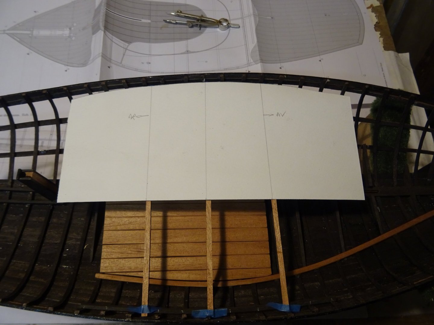
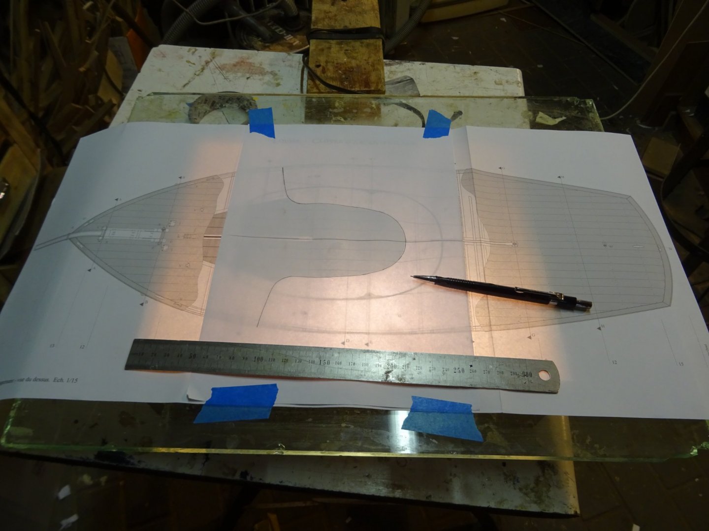
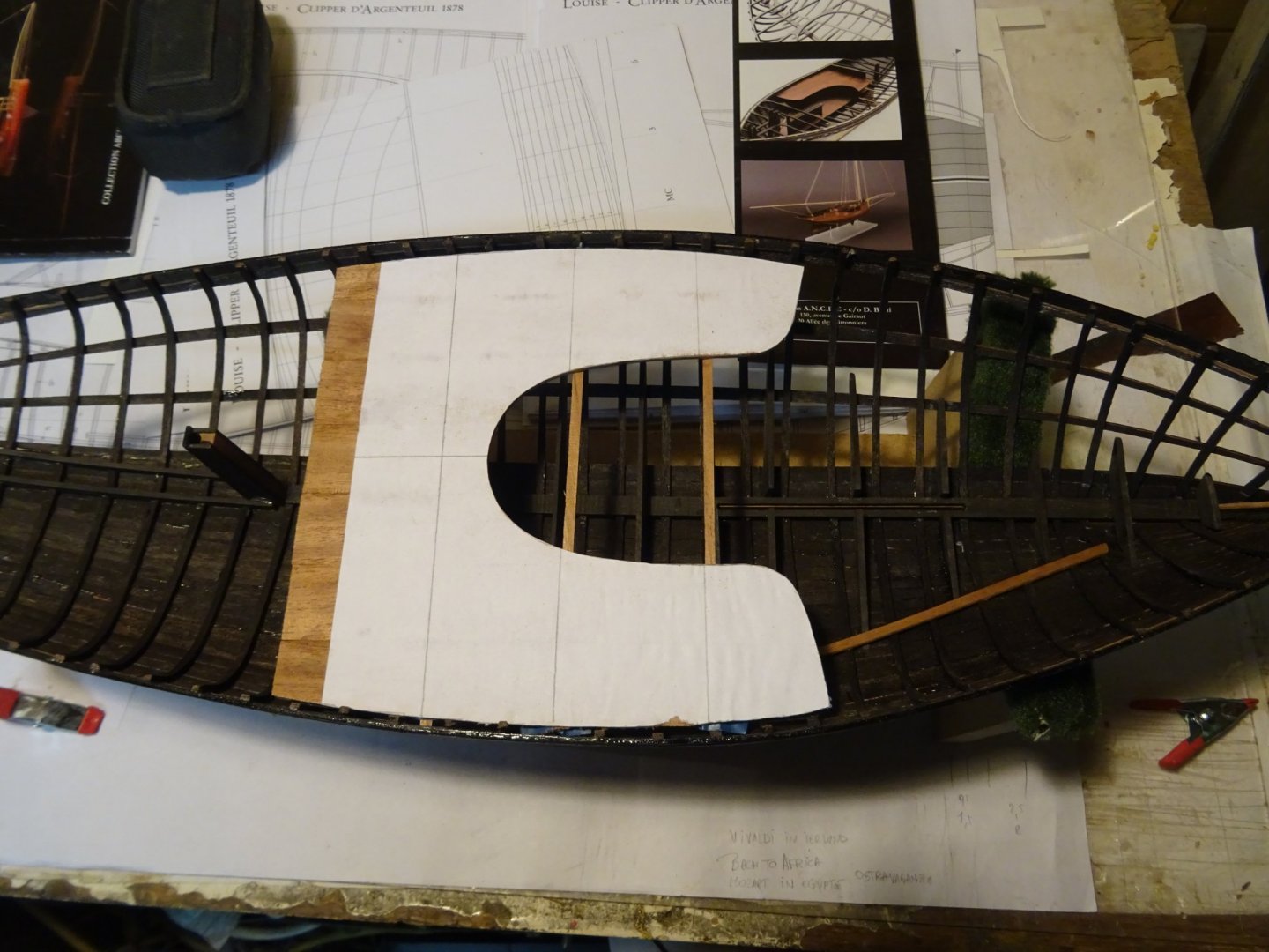
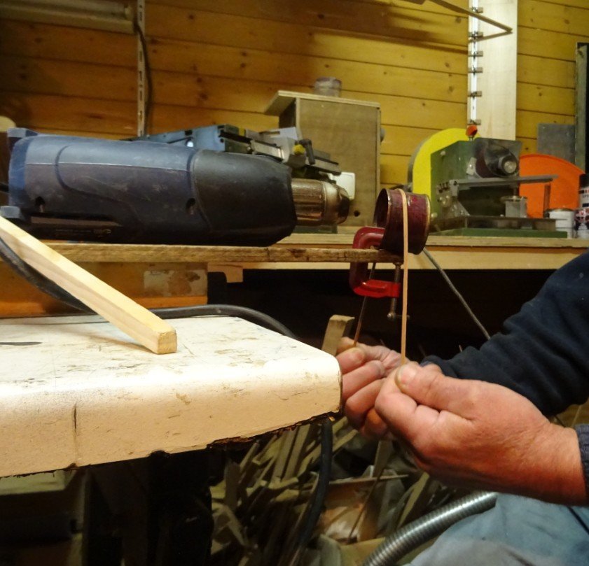
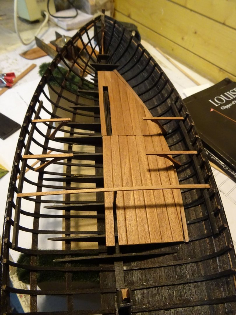
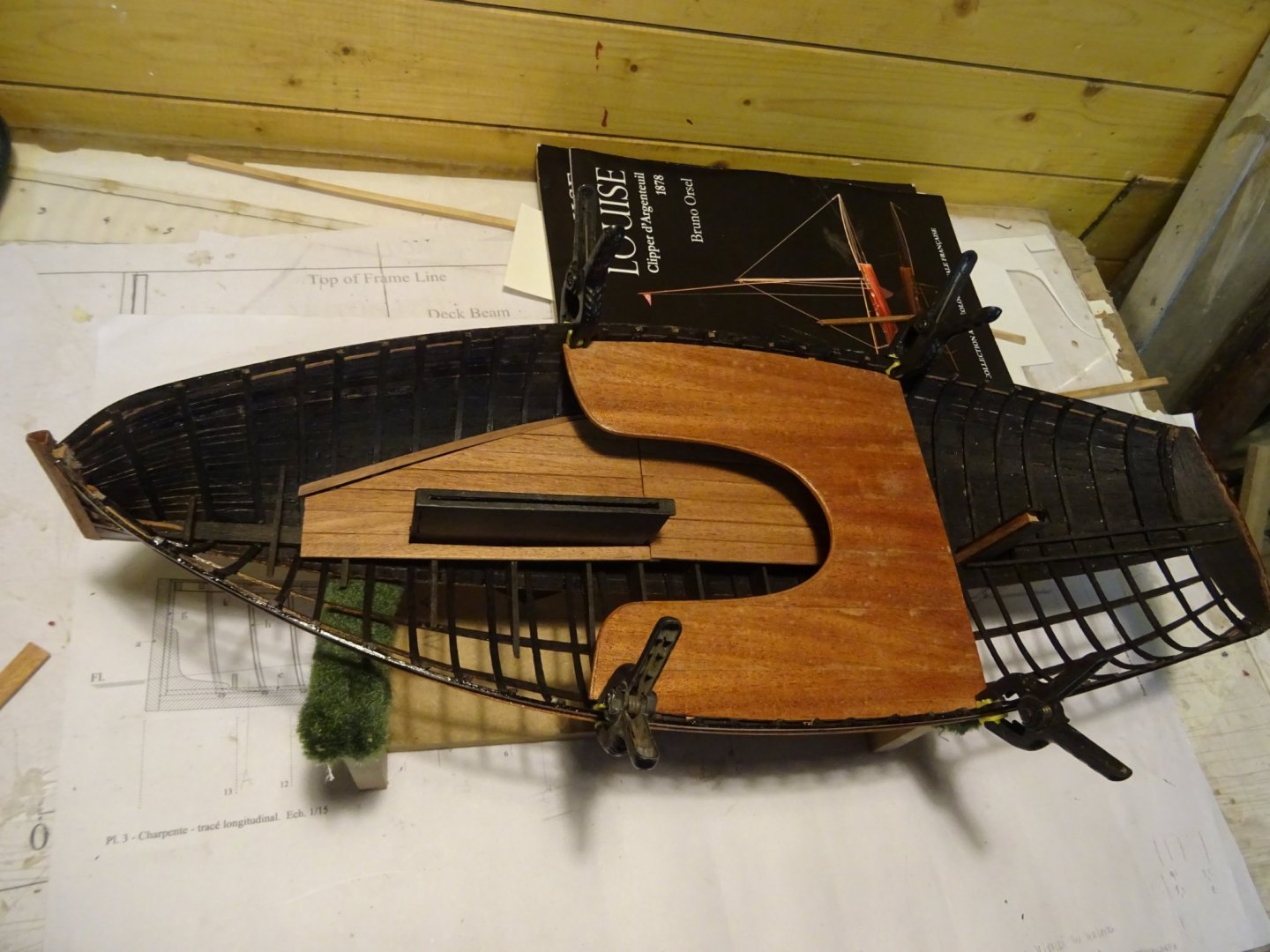
11. Thwart The outsides of the thwart are laying on a rising. The risings are made of ebony. More to midship the thwart is supported by support beams. The two front beams do not run the full width of the hull, but are interrupted in the middle. I leave them whole for the sake of working for now. With the bottom boards (center board case removed): Without the bottom boards: The support beams rest on a strut. Making a template to saw the strut. The forward struts placed provisionally. The rear support beam runs from side to side and is supported in the middle by a pillar. Turning the ebony pillar with the lathe. The three support beams with pillar and struts. I repeat: the two forward beams will be interrupted in the middle. The thwart will be made of mahogany, I make a template to saw it out. Determining the shape of the hull sides. First at one side: then also the other side: I draw the shape of the thwart on the template with the help of an improvised light box. Here the thwart is glued and sawn. Fitting it. I want to finish the curved inside of the thwart with a thin frame. To give the frame its curved shape, I make an improvised bending iron. I secure a can on the workbench and aim the paint burner in the can. The wet frame can now easily be bent round the can into the desired shape in two directions. The frame is now glued in place on the thwart. The center of the two front support beams is now cut away. Fitting the finished thwart. Nothing (neither bottom boards nor thwart) is glued yet. Thank you very much for reading this log and for for your likes.


- 153 replies
-
- 11
-
-

-
- Ancre
- Bruno Orsel
- (and 2 more)