HOLIDAY DONATION DRIVE - SUPPORT MSW - DO YOUR PART TO KEEP THIS GREAT FORUM GOING! (89 donations so far out of 49,000 members - C'mon guys!)
×


G.L.
-
Posts
1,553 -
Joined
-
Last visited
Content Type
Profiles
Forums
Gallery
Events
Everything posted by G.L.
-
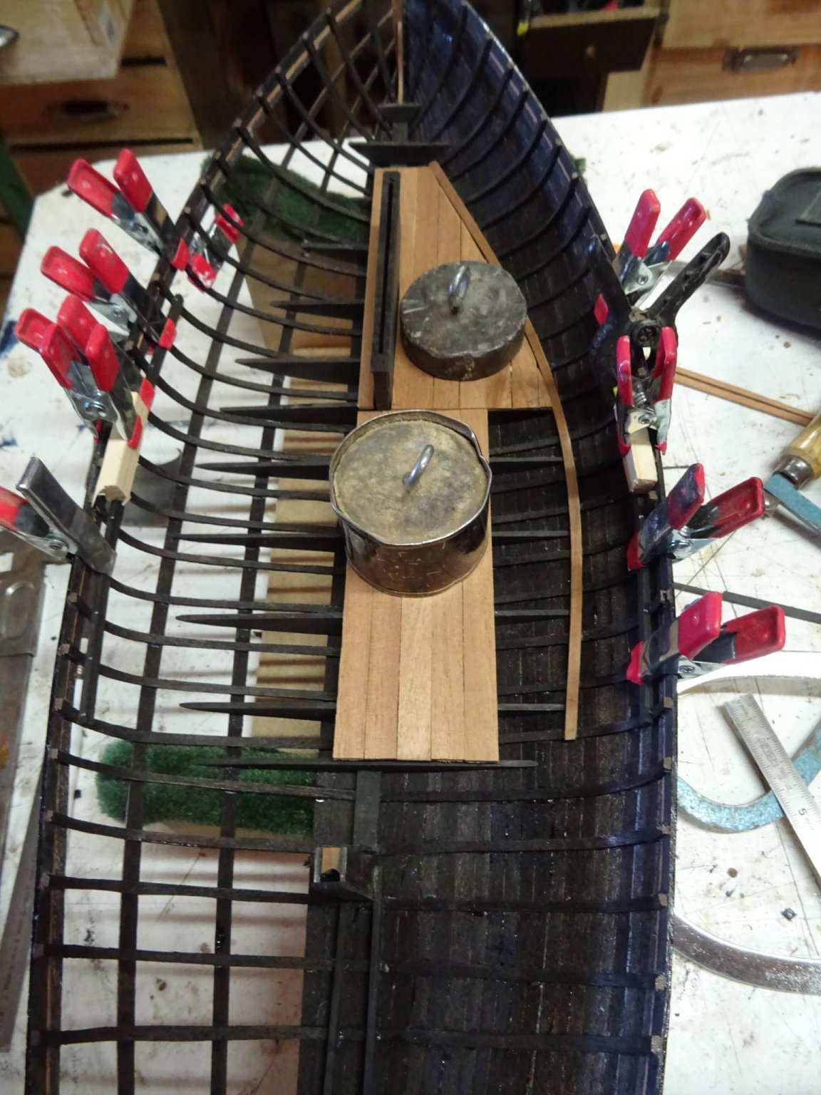
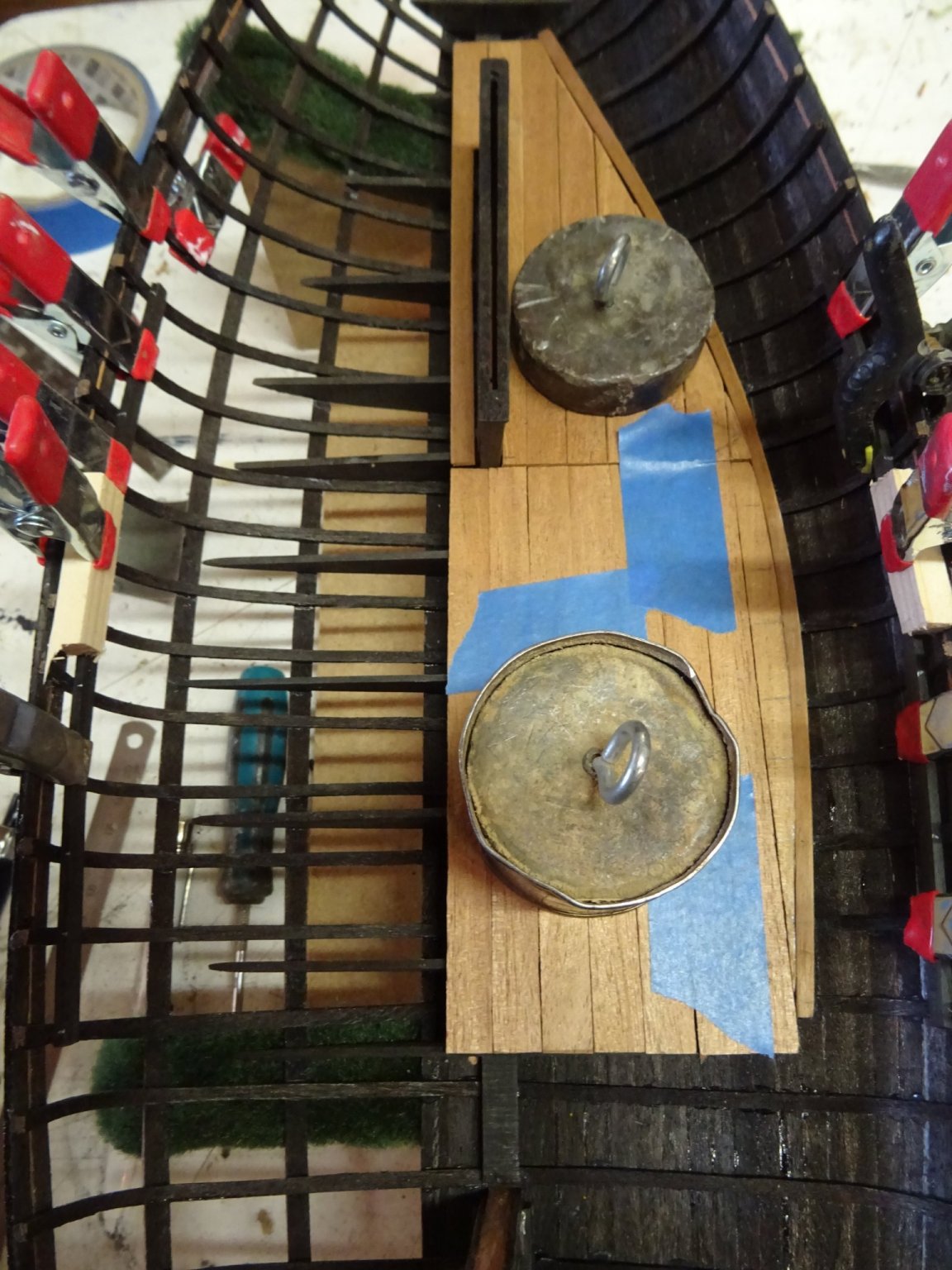
 10. Bottom boards I start with gluing the stringer at the starboard side. At port side (the open side) the bottom boards will not be placed. Starting to puzzle the bottom boards. The boards are still all loose, I use a weight to keep them in place during the measurement. While making the bottom boards I glued the thwart risings already into place at both sides. The boards are complete. The only have to be glued and the back still has to be cut straight. Thank you very much for reading this log, for your likes and for all your encouraging reactions. Till next week!


- 153 replies
-
- 7
-

-
- Ancre
- Bruno Orsel
- (and 2 more)
-
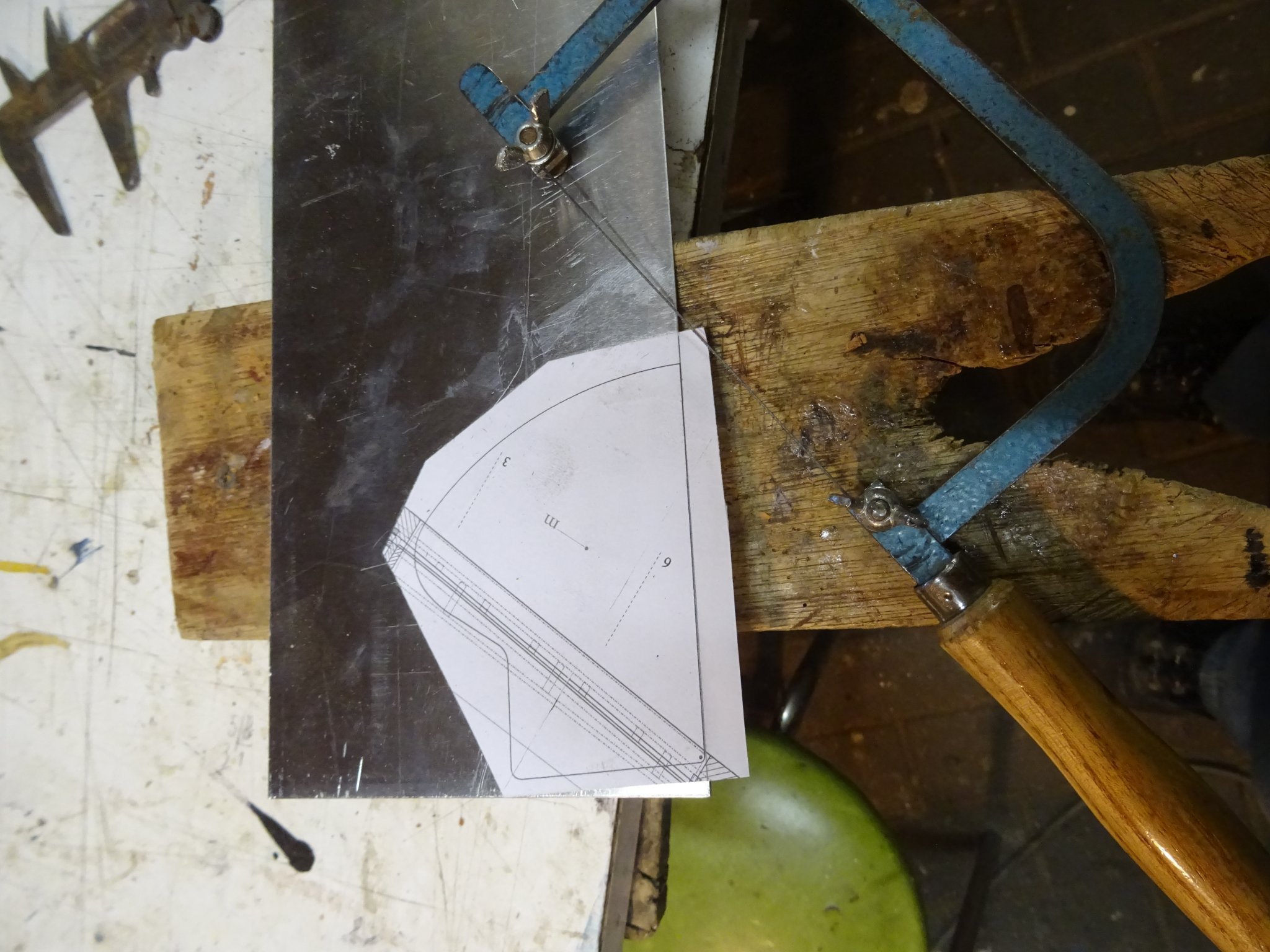
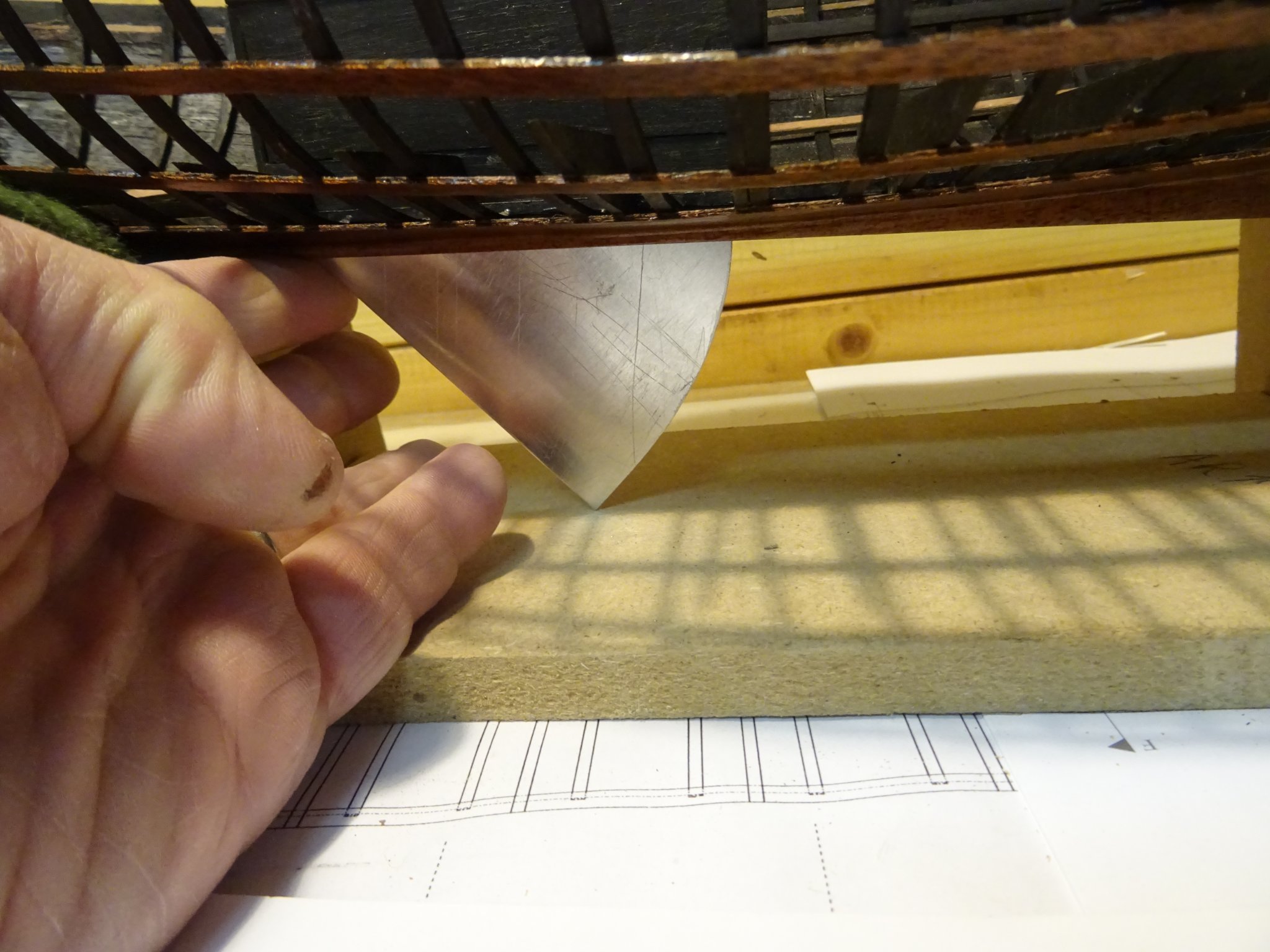
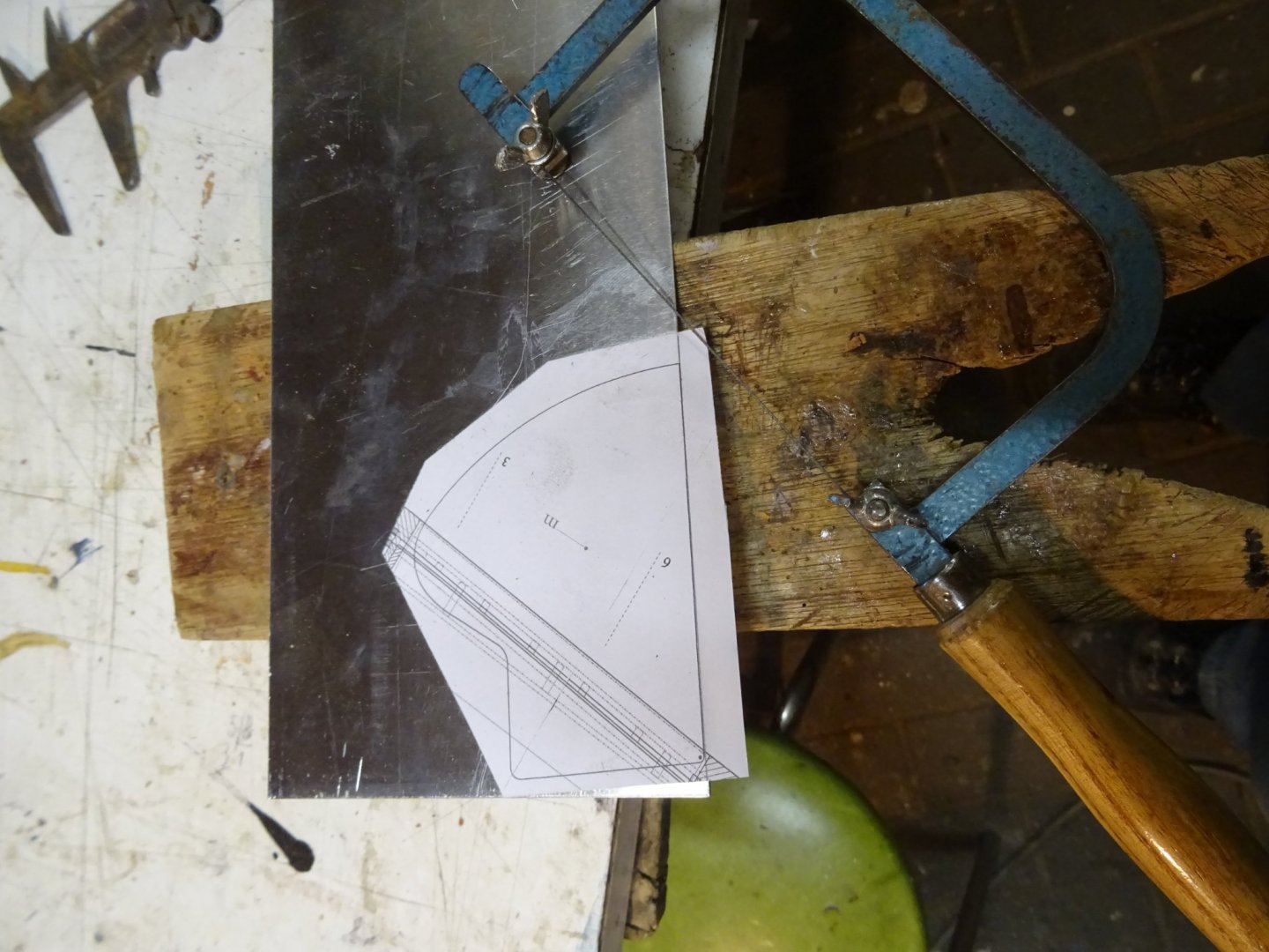
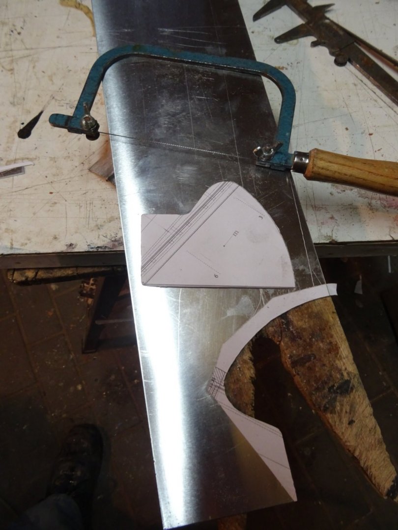
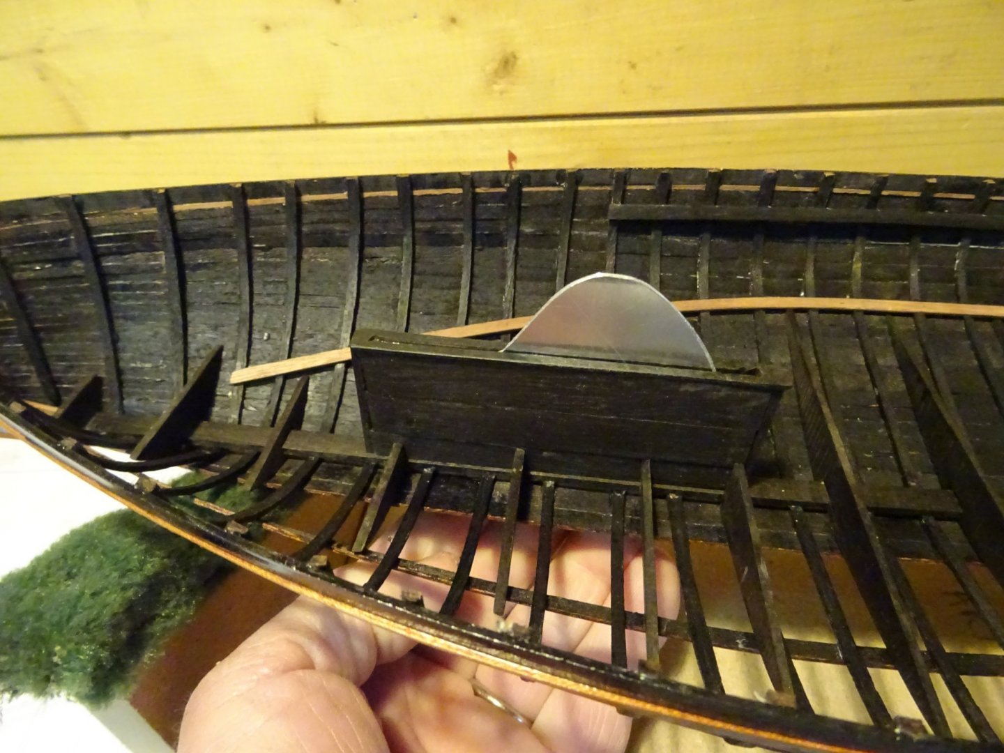
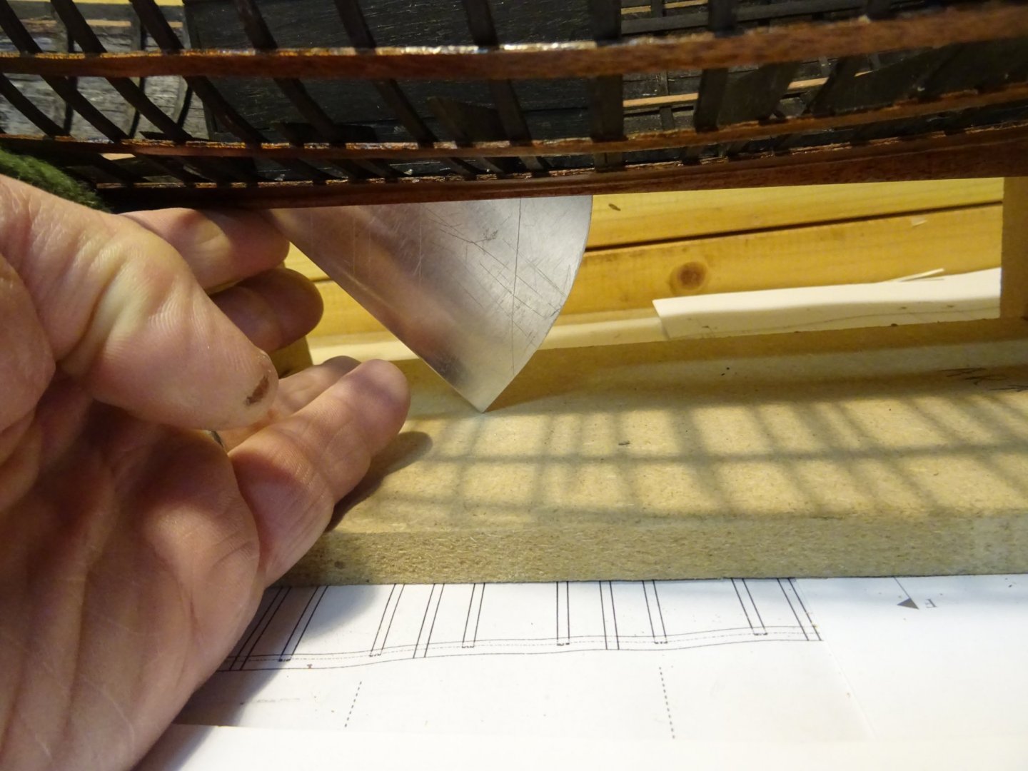
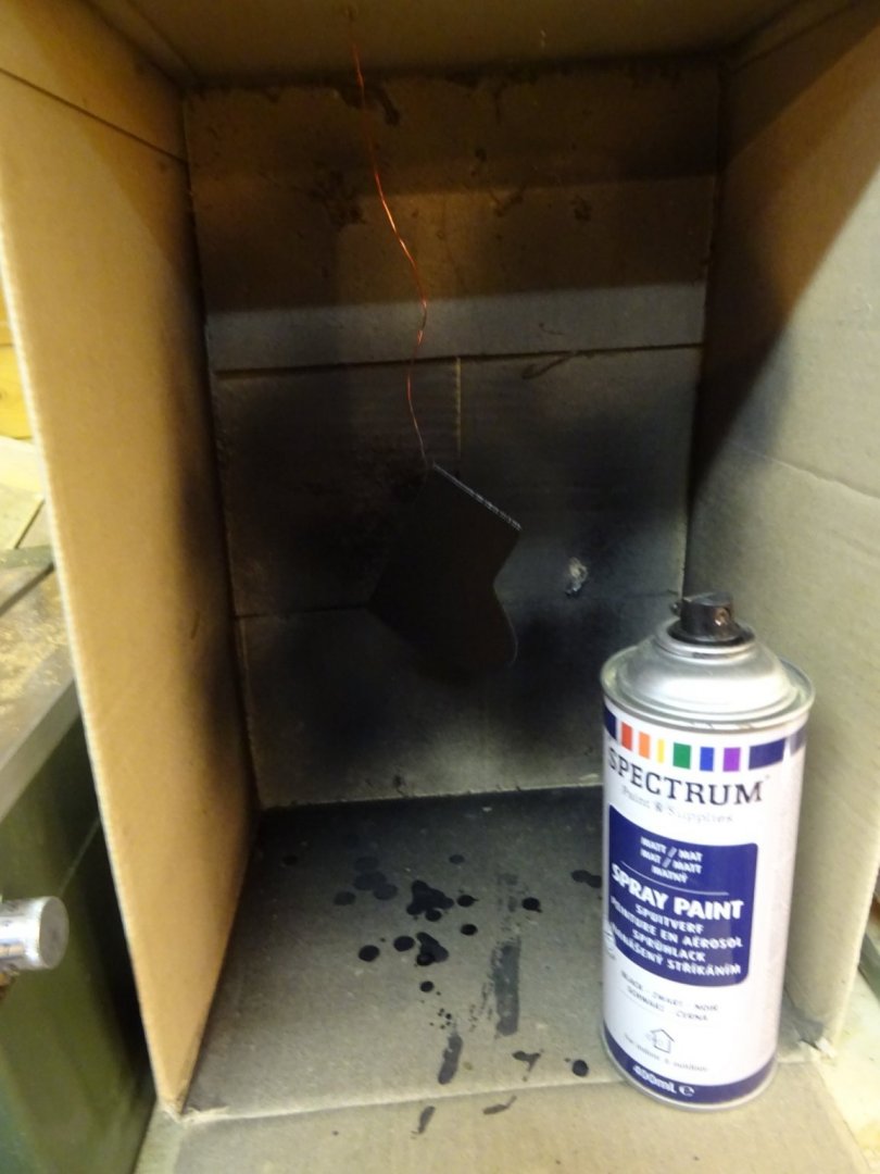
9. Centerboard Case and Centerboard The centerboard case is built on two beams with a recess for side boards at each side. When the side boards are glued, it can be fitted in the hull. Now the case fits, the cover plate can be glued. At this stage I don't glue the centerboard case into place yet. The center board is sawn from an 1.5 mm aluminum plate. Fitting the board and checking if it can be lowered and hauled smoothly. The centerboard is painted in black. I use a cardboard box as a spray booth (the centerboard is hanging in it on a metal wire. A bit hard to see on the photo).

- 153 replies
-
- 7
-
-
- Ancre
- Bruno Orsel
- (and 2 more)
-
Yves, you made me curious. I join the line of followers
- 321 replies
-
- 7
-
-
- Finished
- Flower-class
- (and 1 more)
-
I agree with all the above comments. A really realistic model. Congratulations!
- 53 replies
-
- 5
-
-

-
- photo etch
- resin
- (and 3 more)
-
MCB, I just discovered your log and read it diagonally. What an interesting project! Tonight I will read your full story again, but this time carefully. I should have discovered this earlier. Congratulations on this beautiful work.
-
Thank very much for your kind comments, Roger, Patrick and Phil
- 153 replies
-
- 2
-
-
- Ancre
- Bruno Orsel
- (and 2 more)
-
That's really nice done at such a small scale. It breathes the atmosphere of the early 20th century. I see the ship plowing through the waves of the Atlantic like this!
- 53 replies
-
- 7
-
-
- photo etch
- resin
- (and 3 more)
-
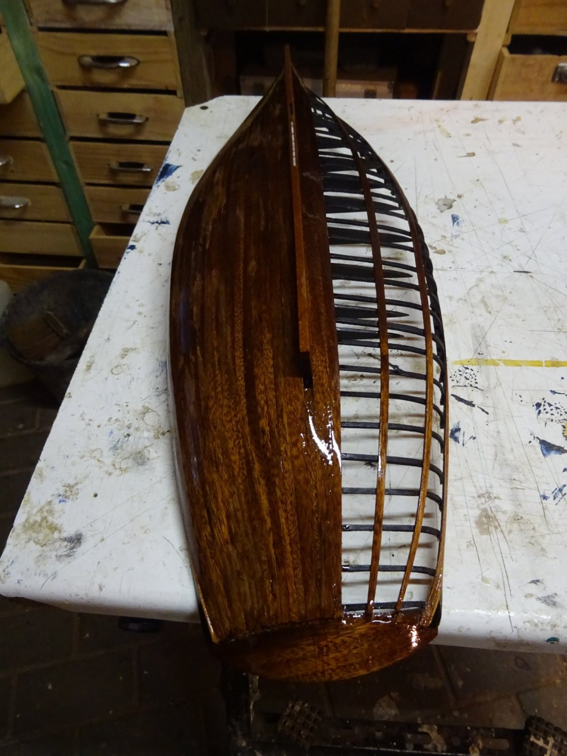
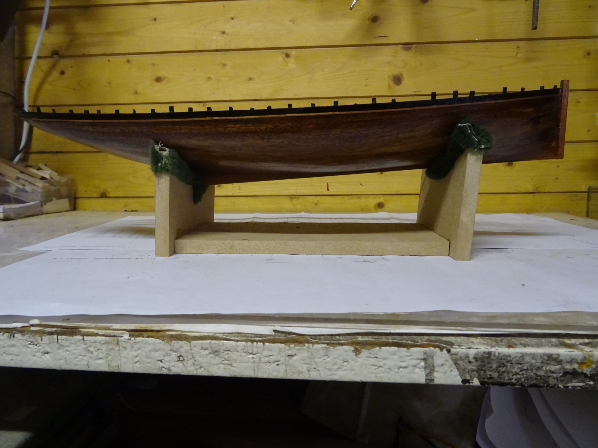
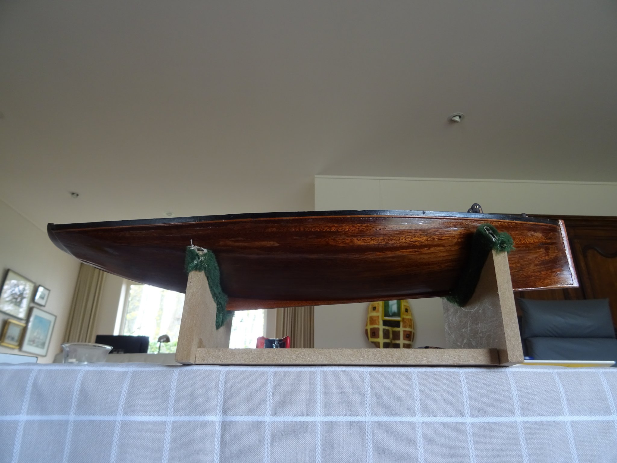
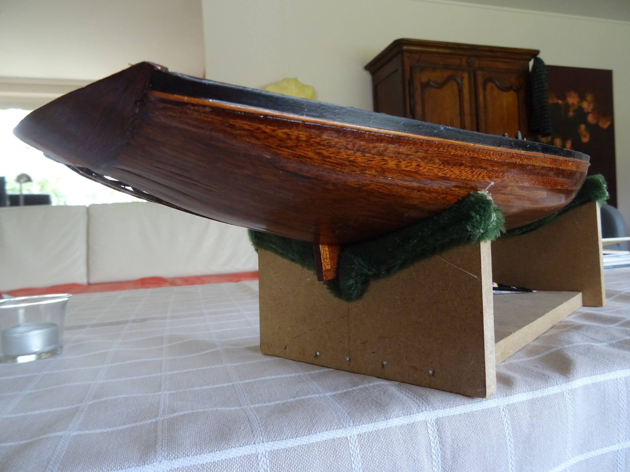
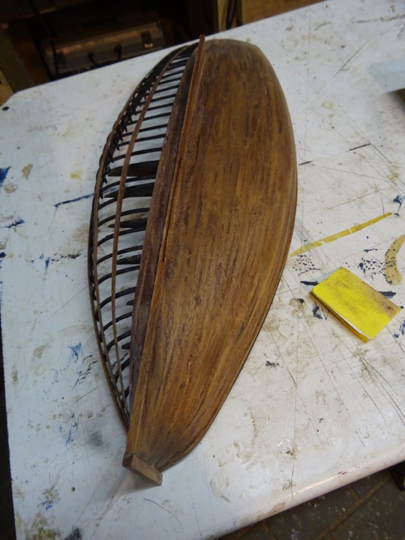
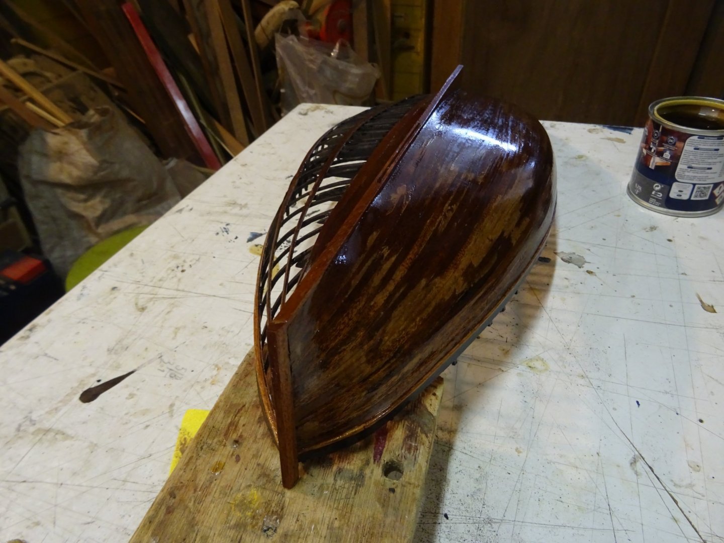
This week, I varnished the hull. It took a week to do so because I had to give five or six layers before I was happy with the result. Between every layer the hull was sanded with fine sand paper. Sanded between two varnishes. A new layer laid. It is always a bit dark in the workshop, therefore some pictures in the living room where the light is better. Thank you very much for reading this log and for your likes. Till next week!


- 153 replies
-
- 9
-
-

-
- Ancre
- Bruno Orsel
- (and 2 more)
-
Hello Patrick. A pin rail in Dutch is a 'nagelbank' in which belaying pins ('korvijnnagels') are placed.
- 756 replies
-
- 2
-
-
-
- galleon
- golden hind
- (and 2 more)
-
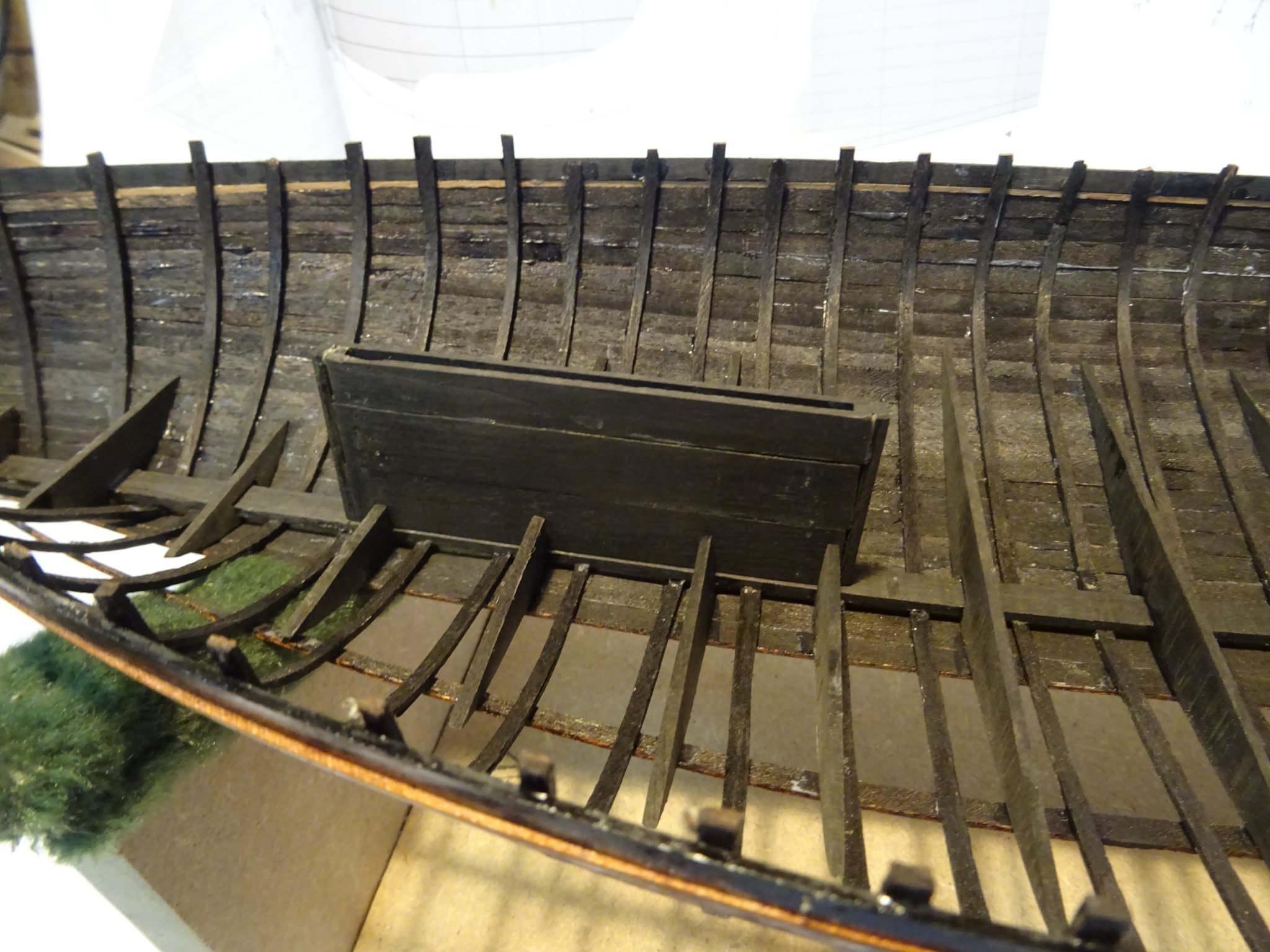
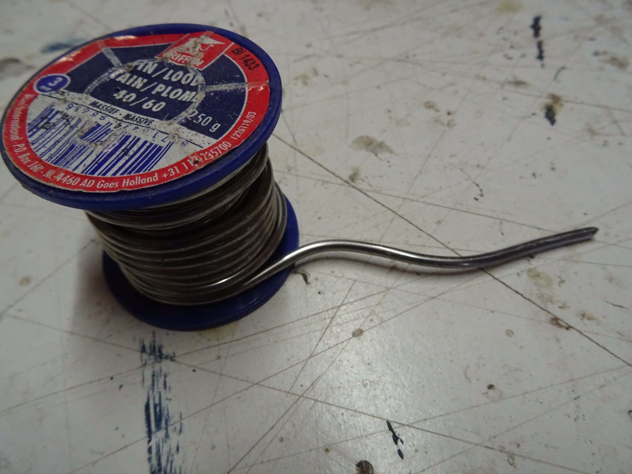
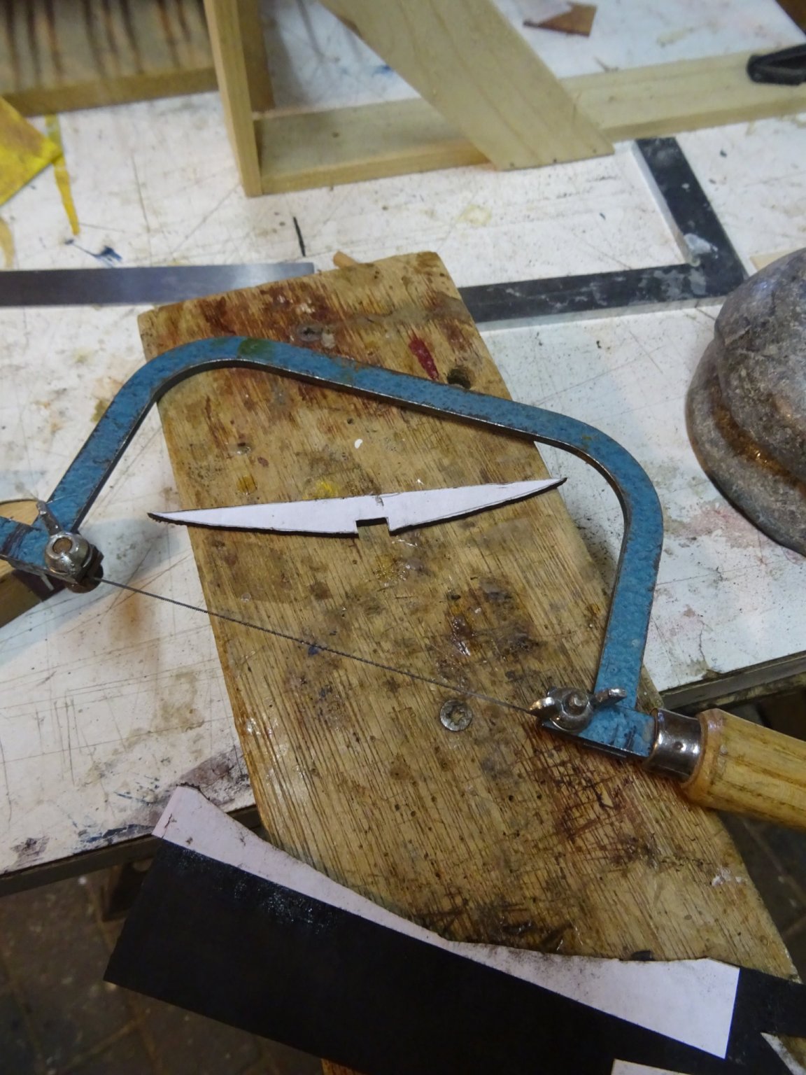
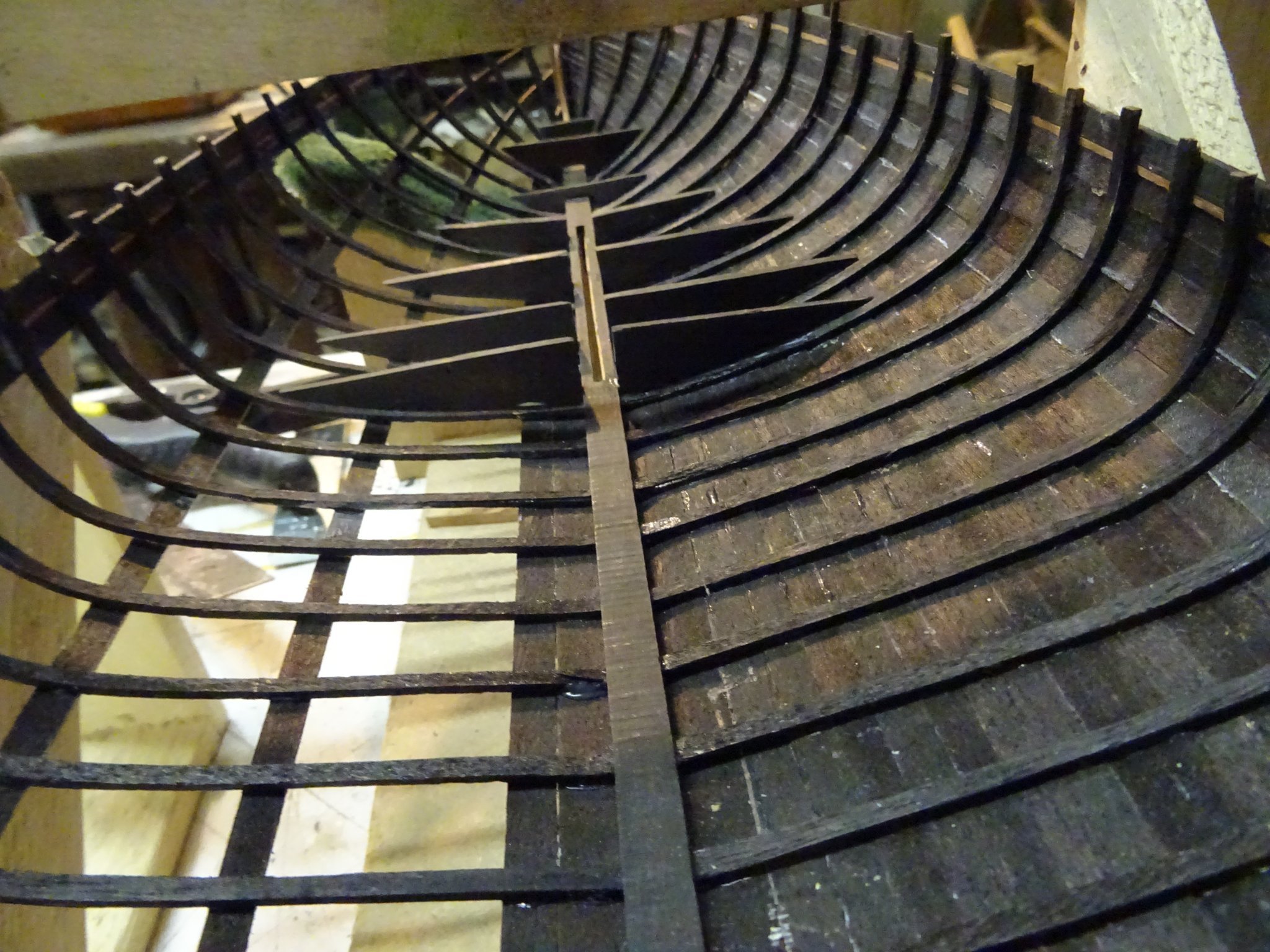
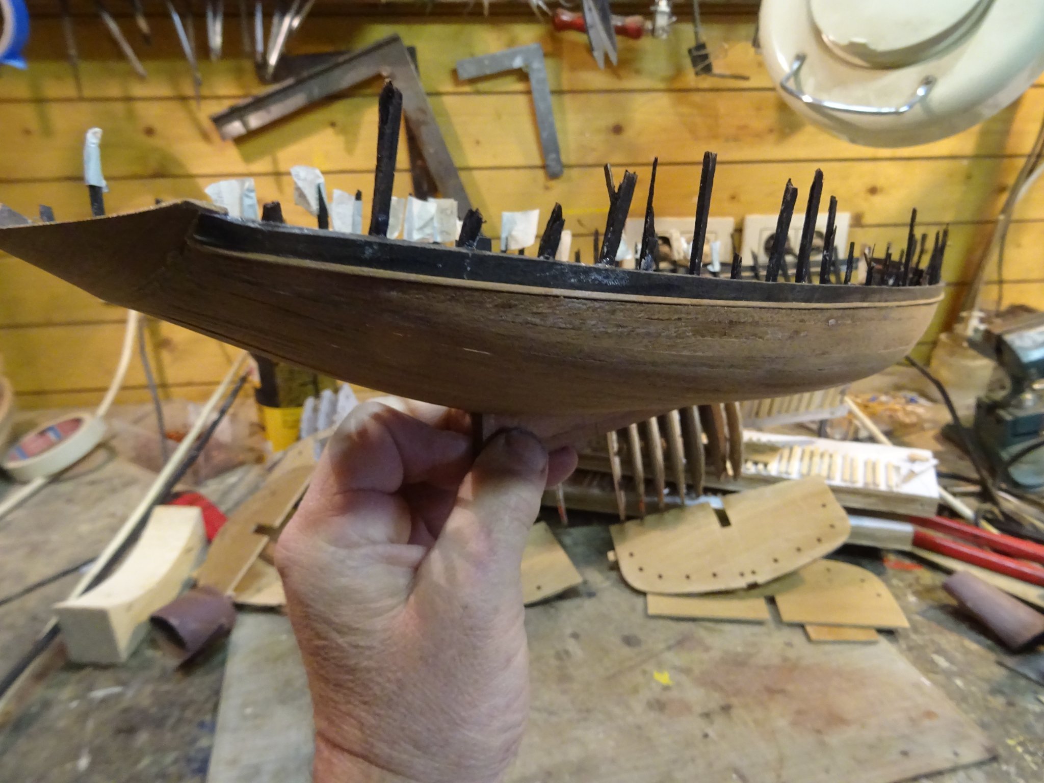
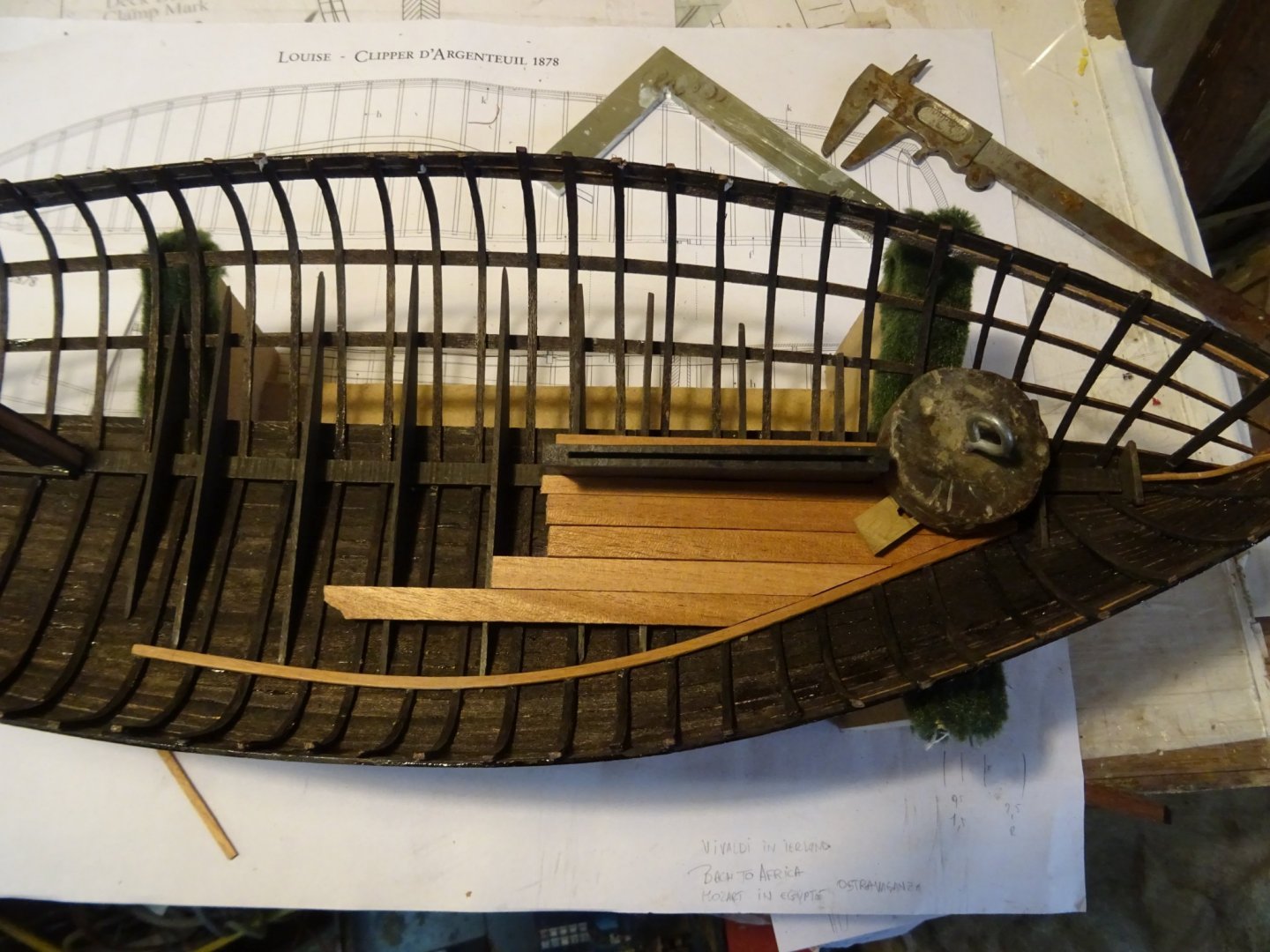
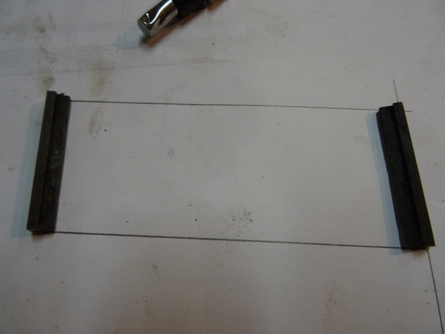
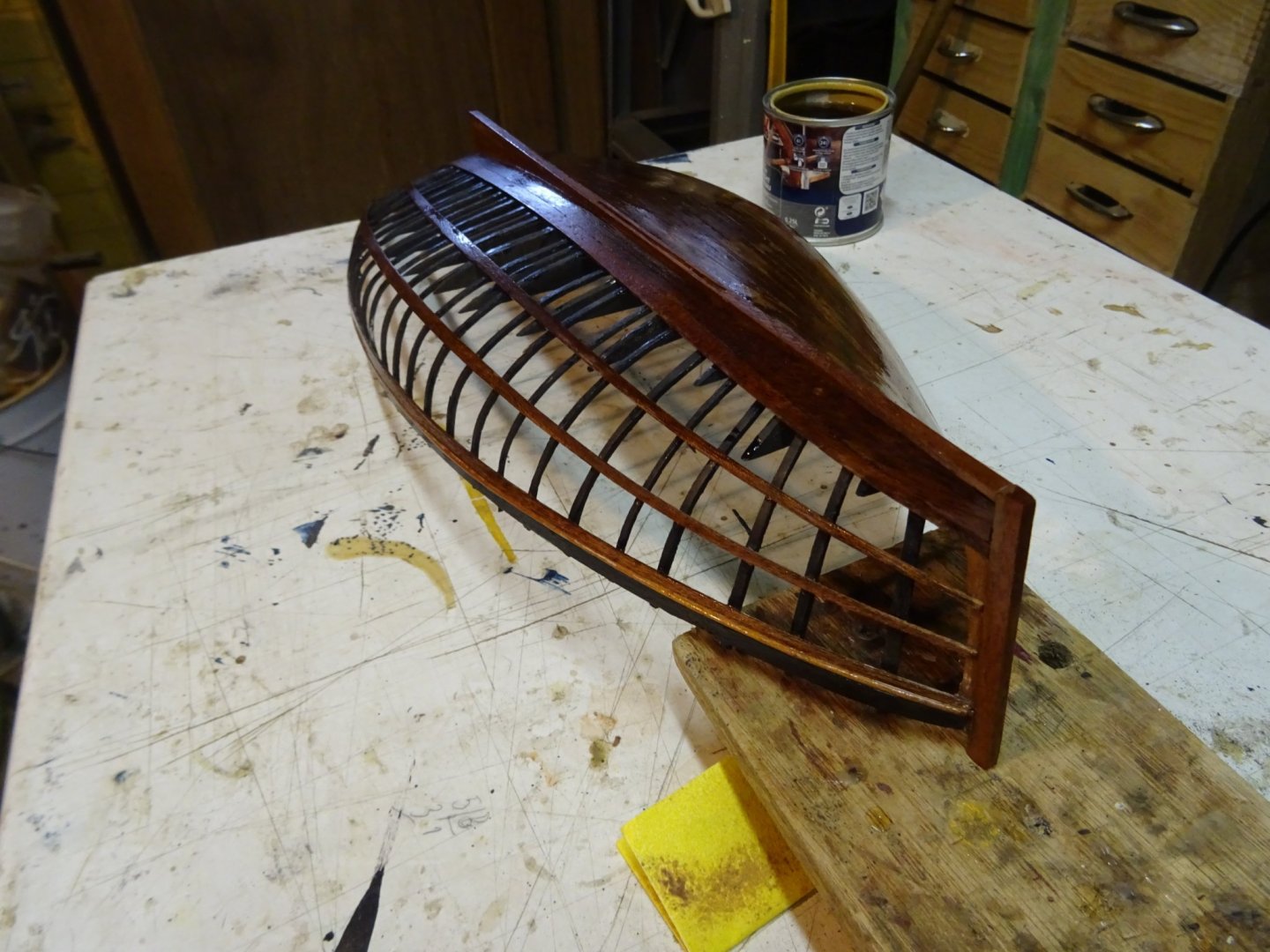
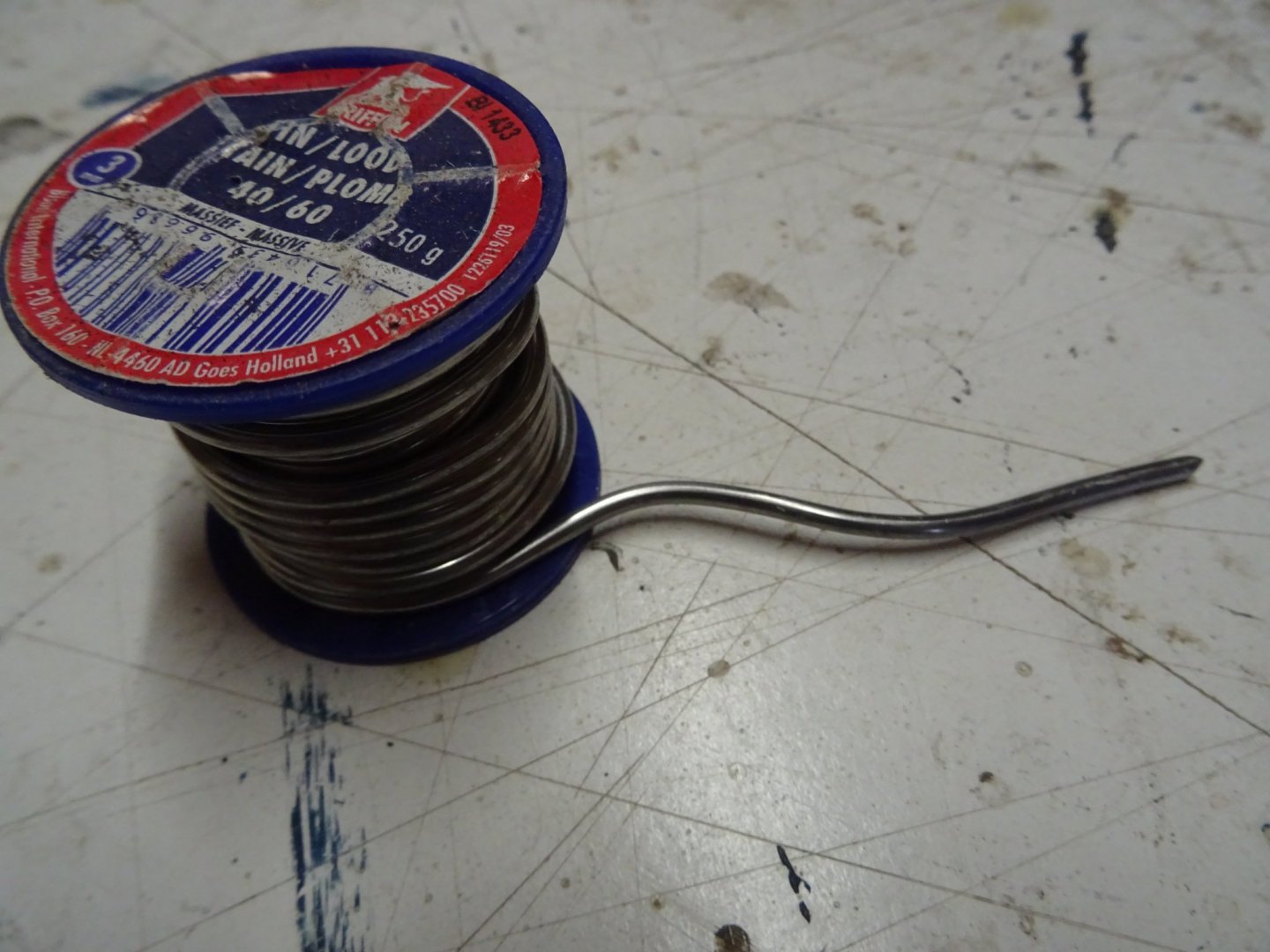
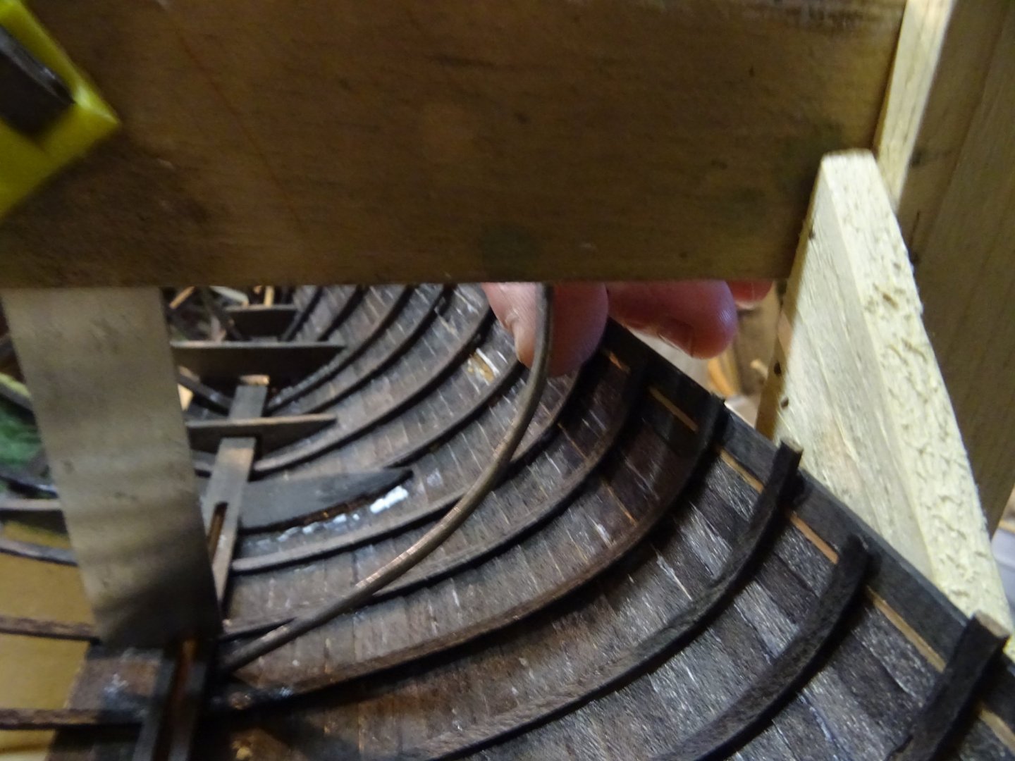
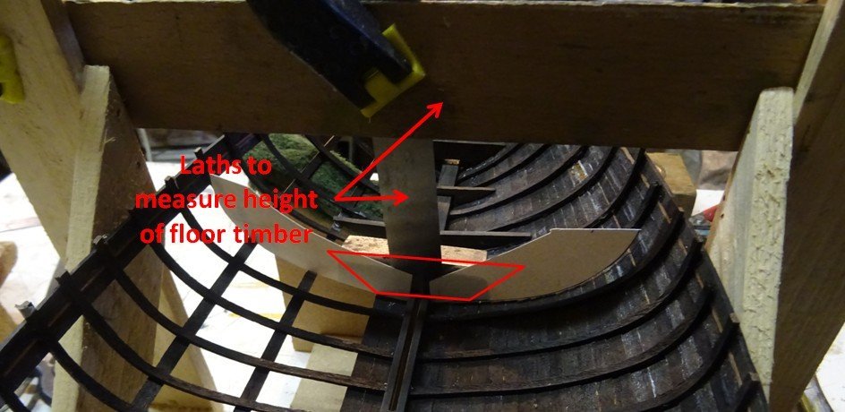
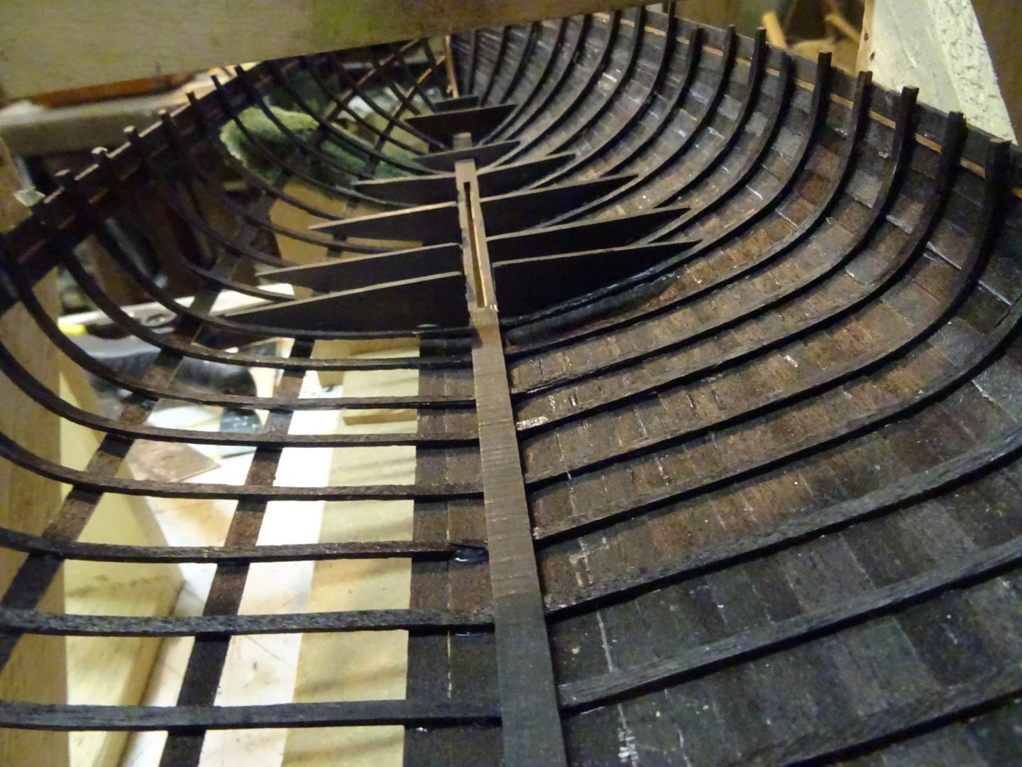
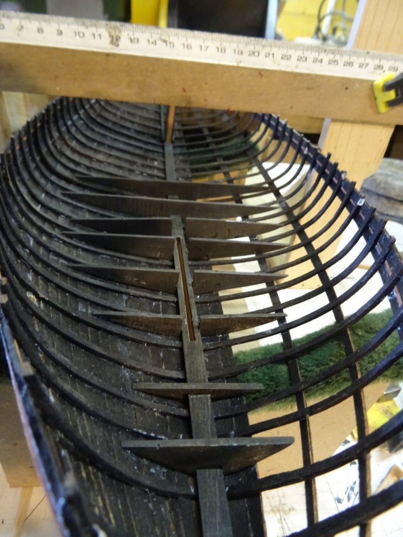
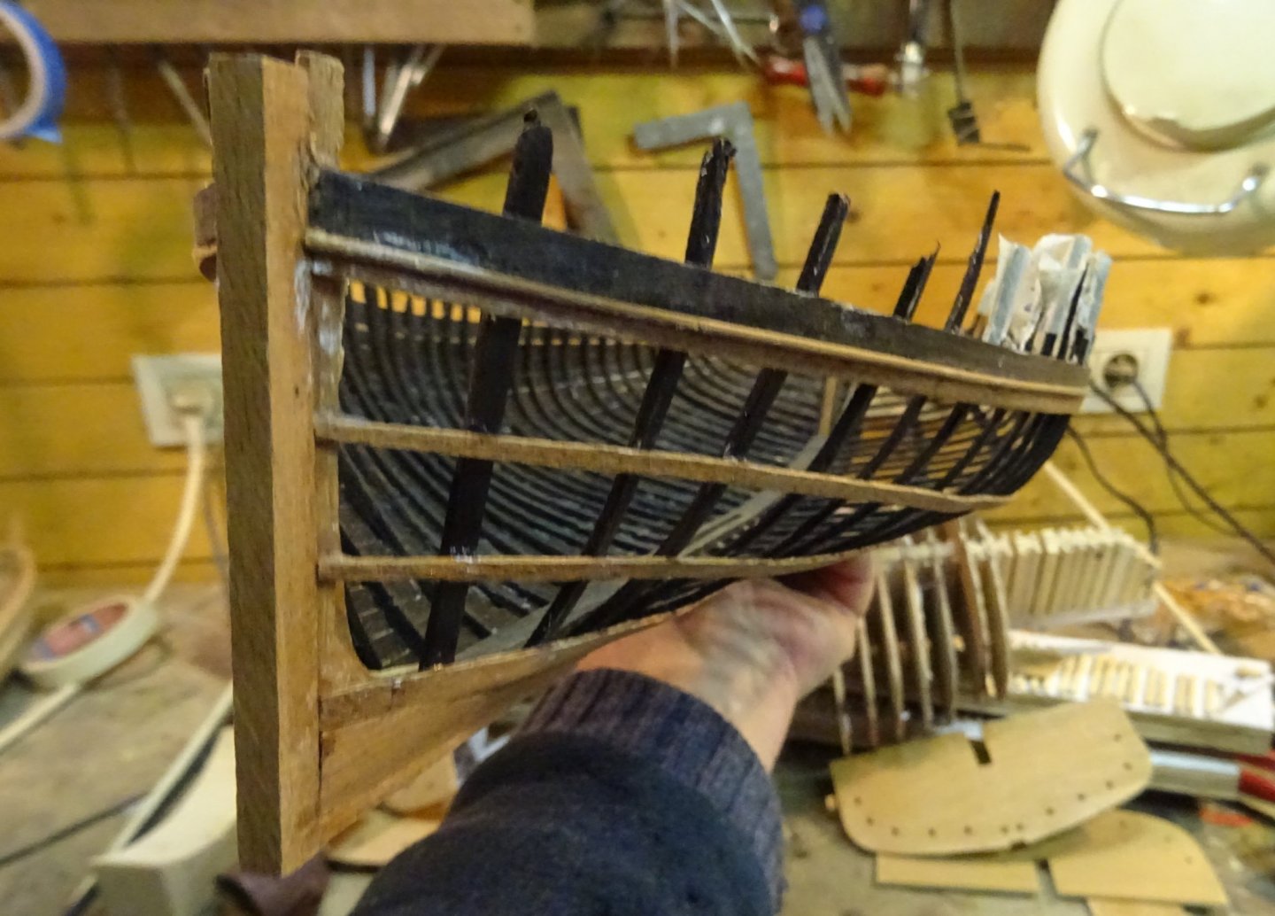
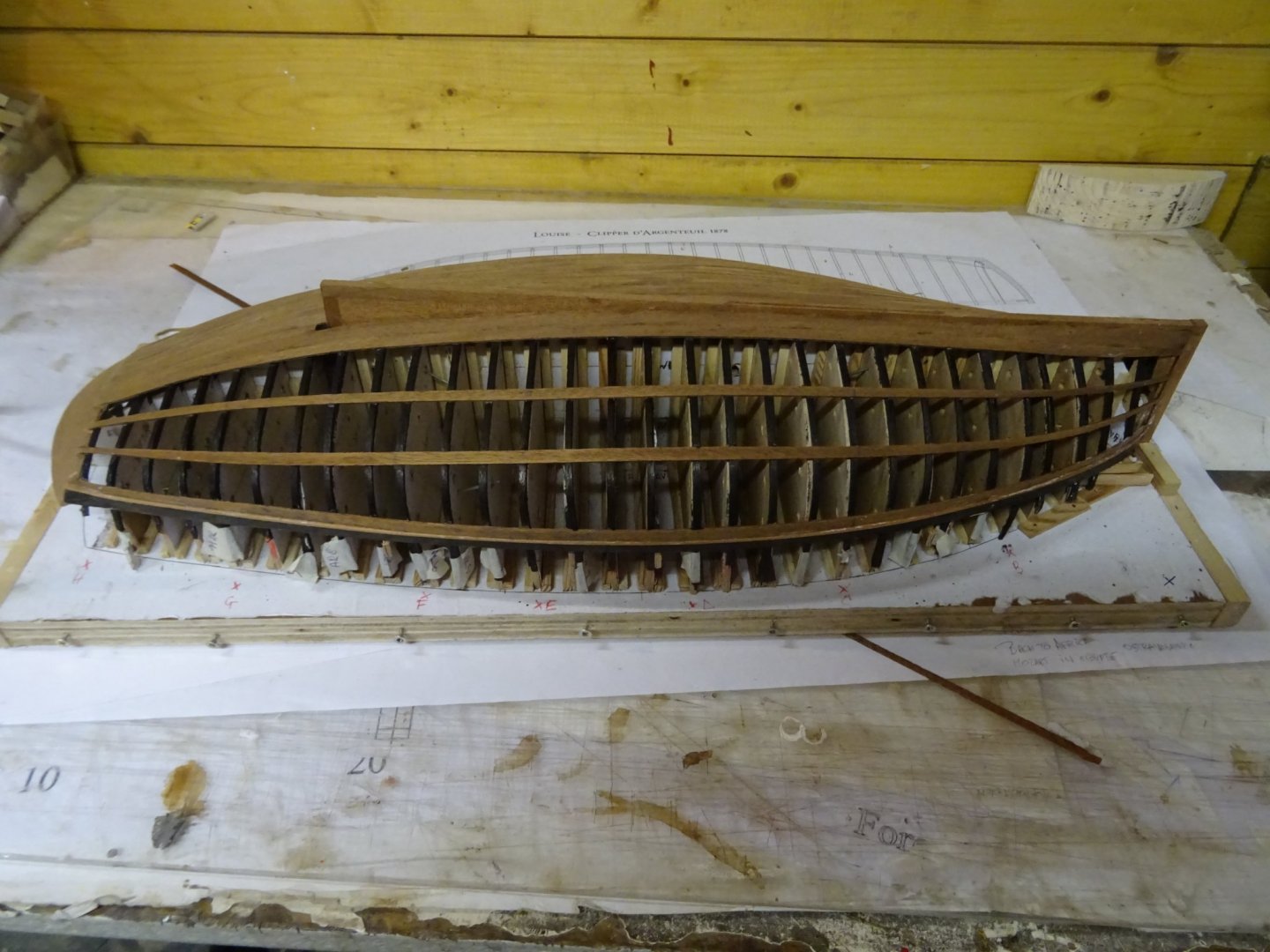
8. Floor timbers The hull is now liberated from the building board, the inside is free accessible to work in it. This week I am making the floor timbers. The floor timbers are not only reinforcements for the hull, but most of them are also the base for the bottom boards. That means that their bottom must have as much as possible the shape of the inside of the hull and that the top of those on which will lay the bottom boards must be at equal and correct height to form stabile base for the boards. To determine the inside shape of the hull where the floor timbers will be placed, I use a piece of thick solder. That can be pressed in hollow shape of the hull. I trace the shape onto stiff paper for both sides and cut them out. I glue them together with another piece of stiff paper just on top of the keelson (red marking, I was a bit lazy in making pictures). A vertical lath, attached to a horizontal lath which can be moved along the hull at a constant height helps to determine the height of the floor timber. The floor timber can now be sawn ... ... fitted and glued. All floor timbers placed. Thank you very much for reading this log, for your likes and for all your kind reactions. Till next week!

- 153 replies
-
- 12
-
-
-
- Ancre
- Bruno Orsel
- (and 2 more)
-
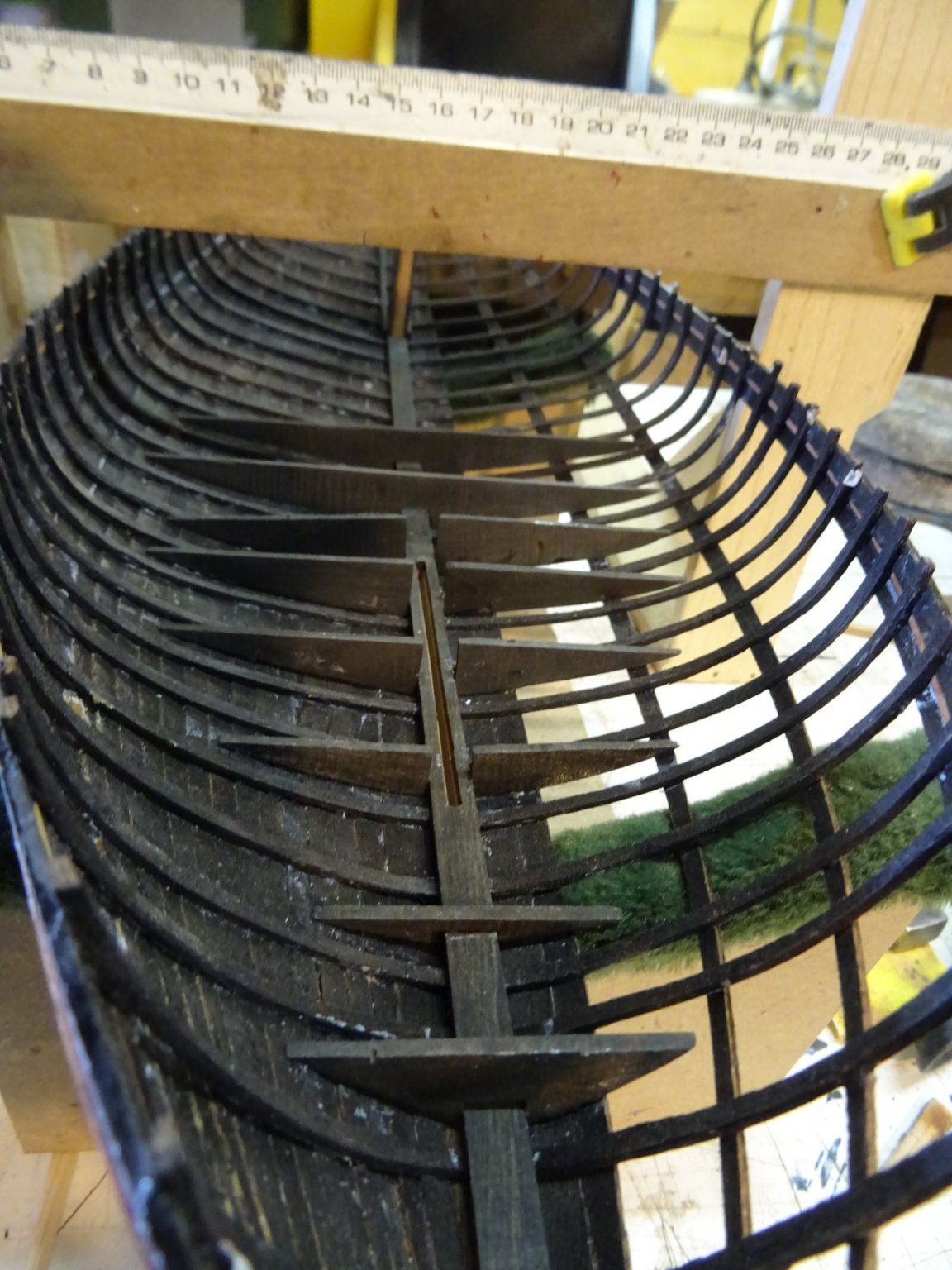
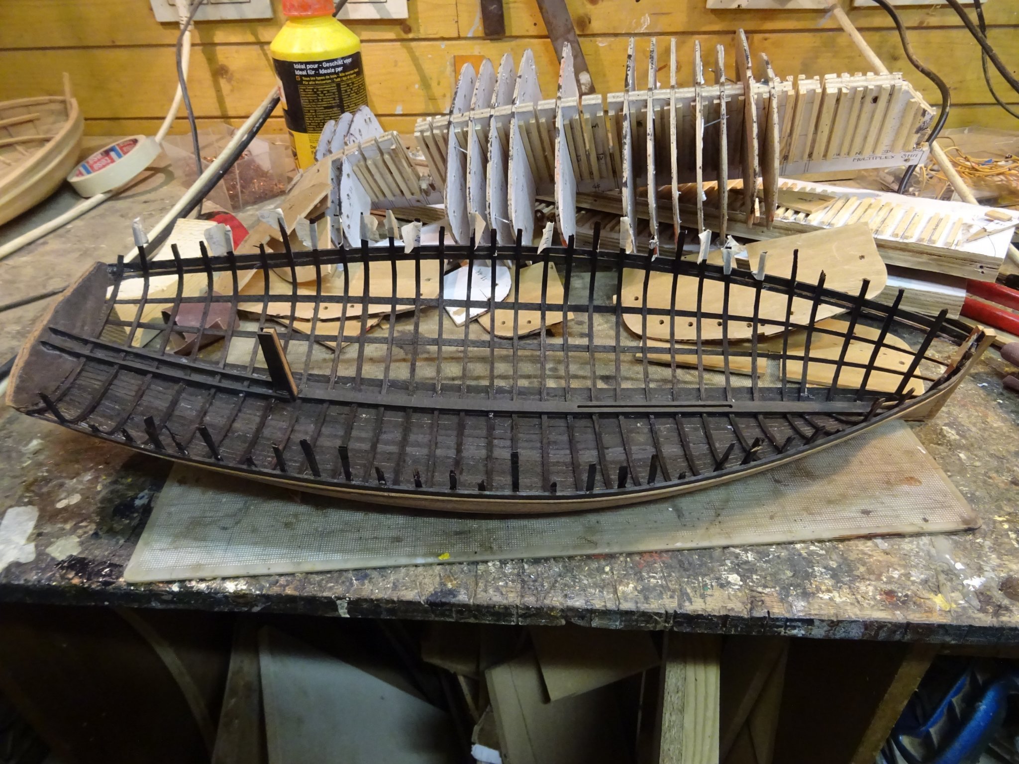
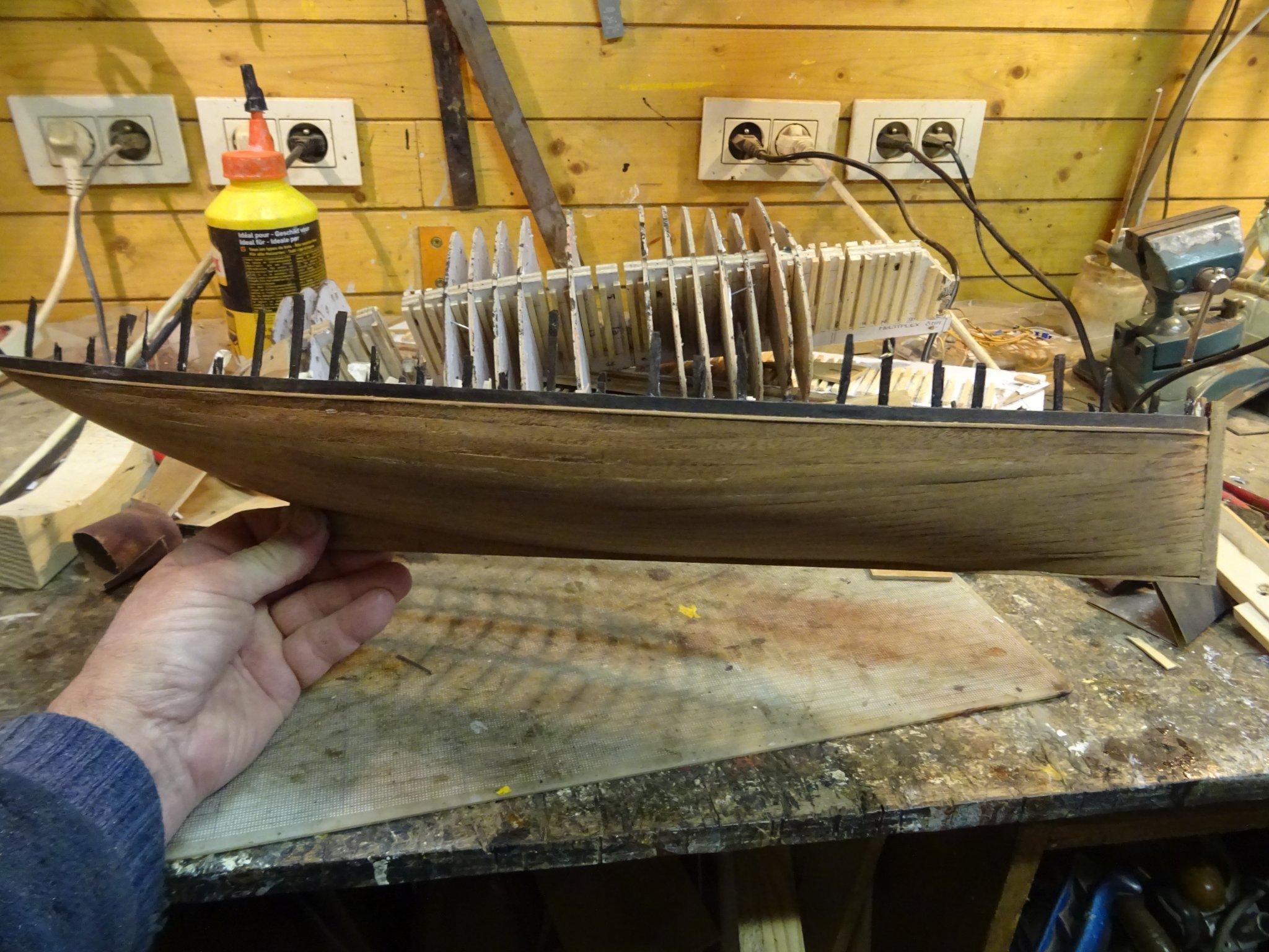
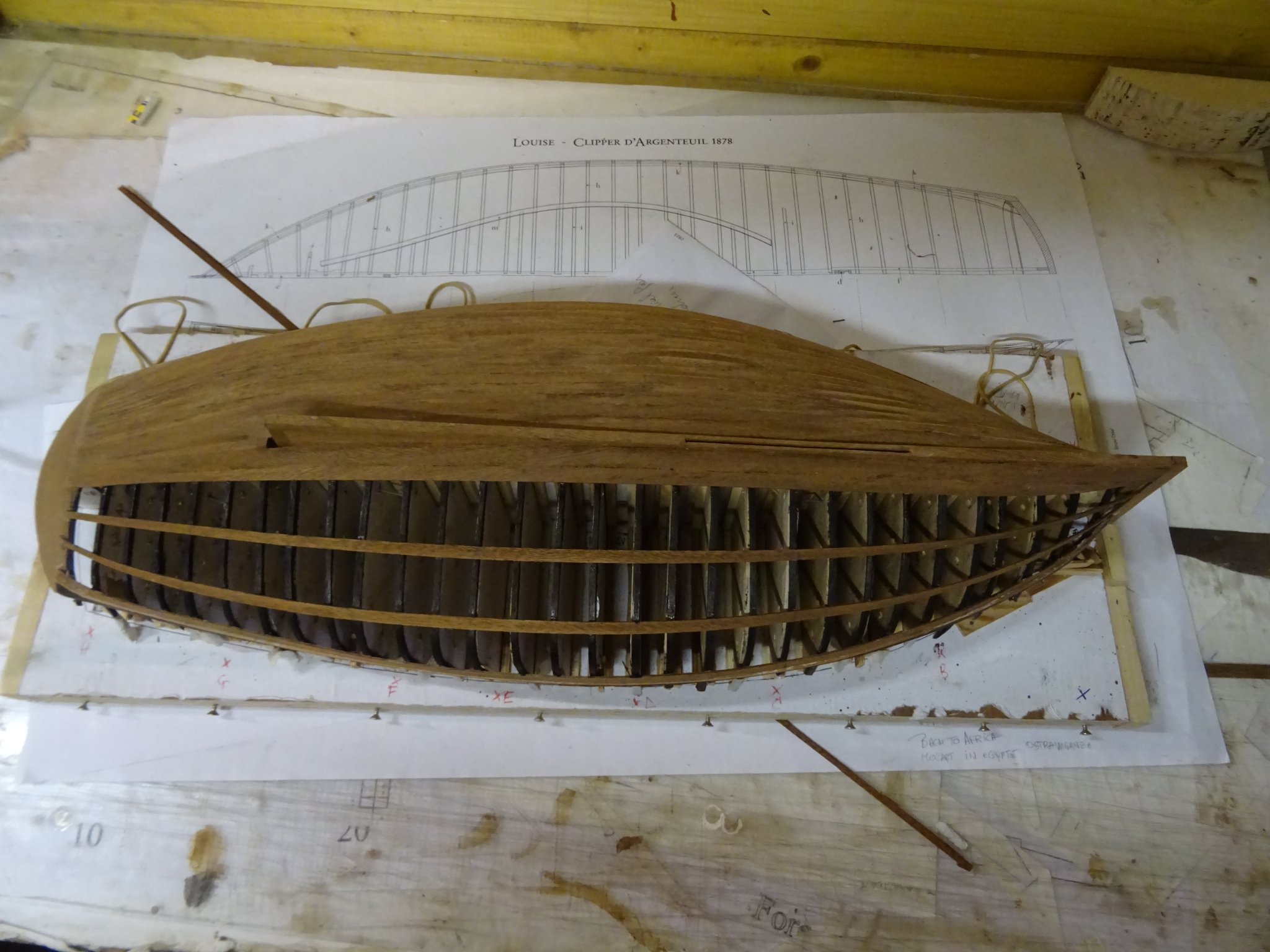
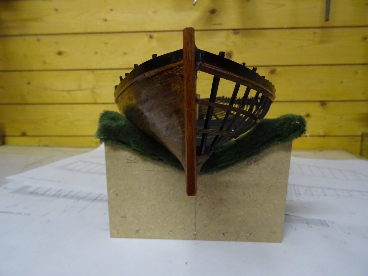
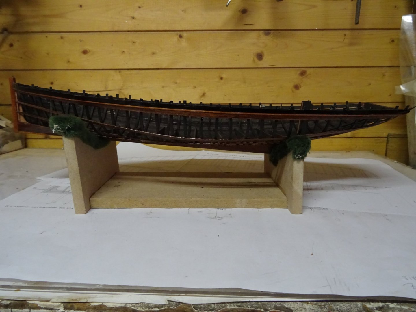
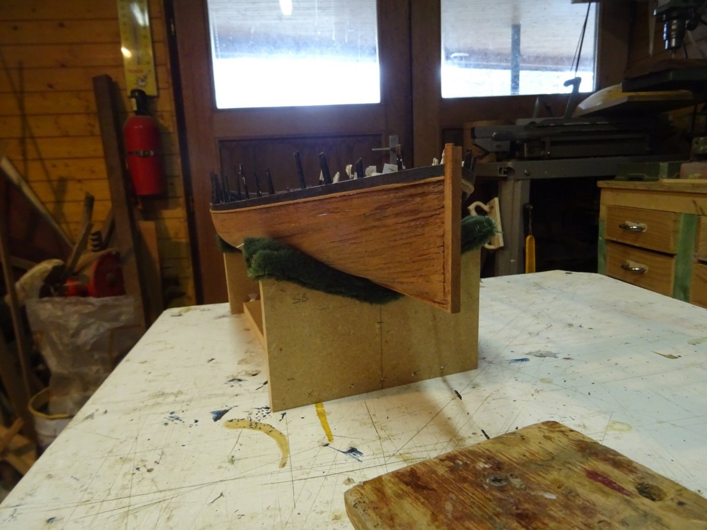
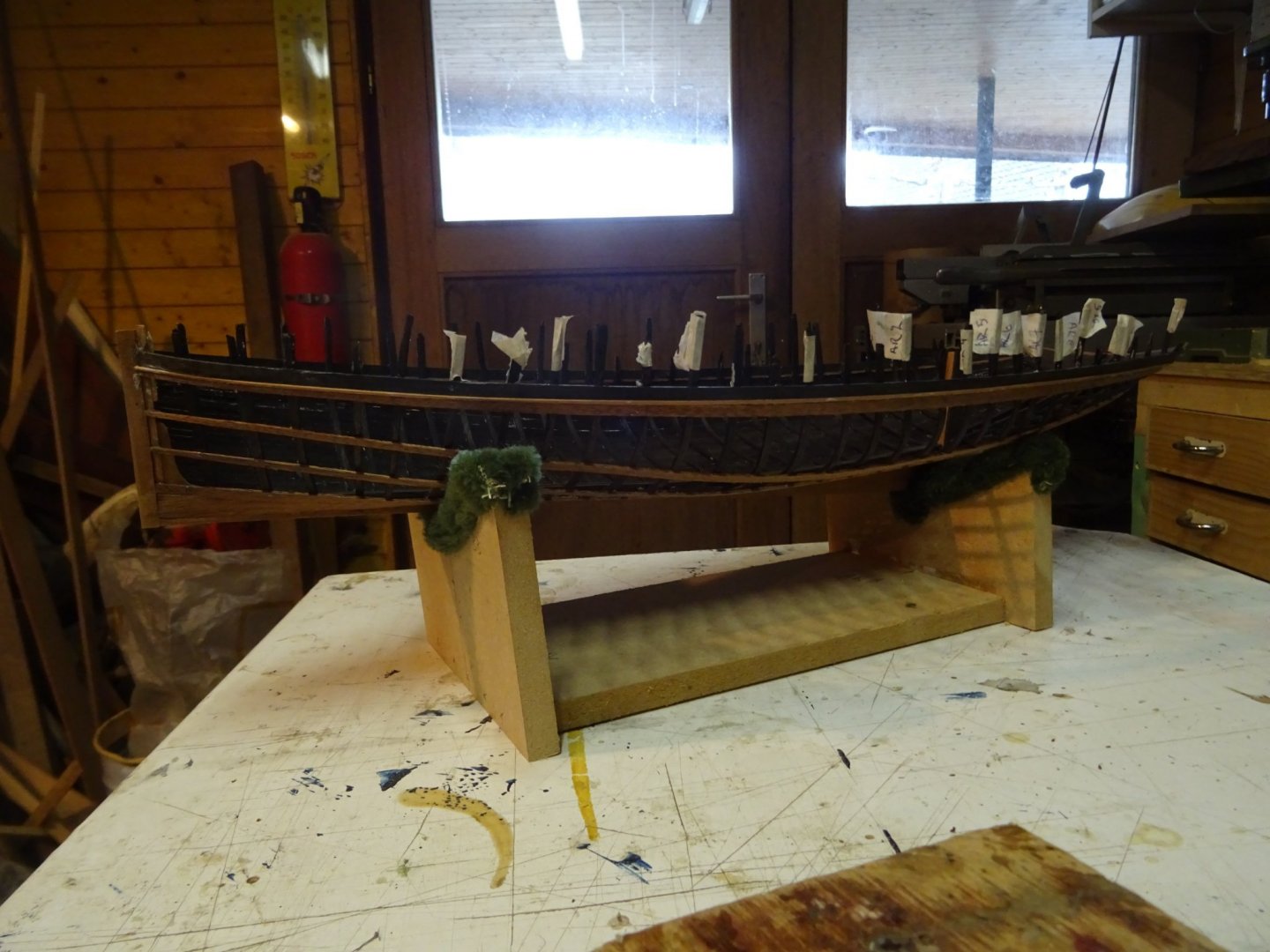
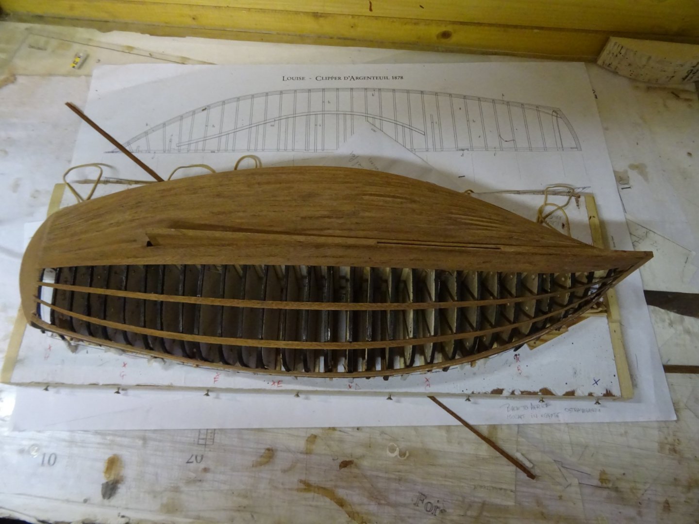
The hull can now be removed from the building board. Better to say the building board can now be dismantled from below the hull. It is feather light. The hull, sitting in its new chair:


- 153 replies
-
- 9
-
-
- Ancre
- Bruno Orsel
- (and 2 more)
-
Welcome on this log, Gary and thank you for your compliments. Thanks, Vaddoc.
- 153 replies
-
- 2
-
-
- Ancre
- Bruno Orsel
- (and 2 more)
-
A very nice half hull model of an elegant boat. Congratulations, Mark!
-
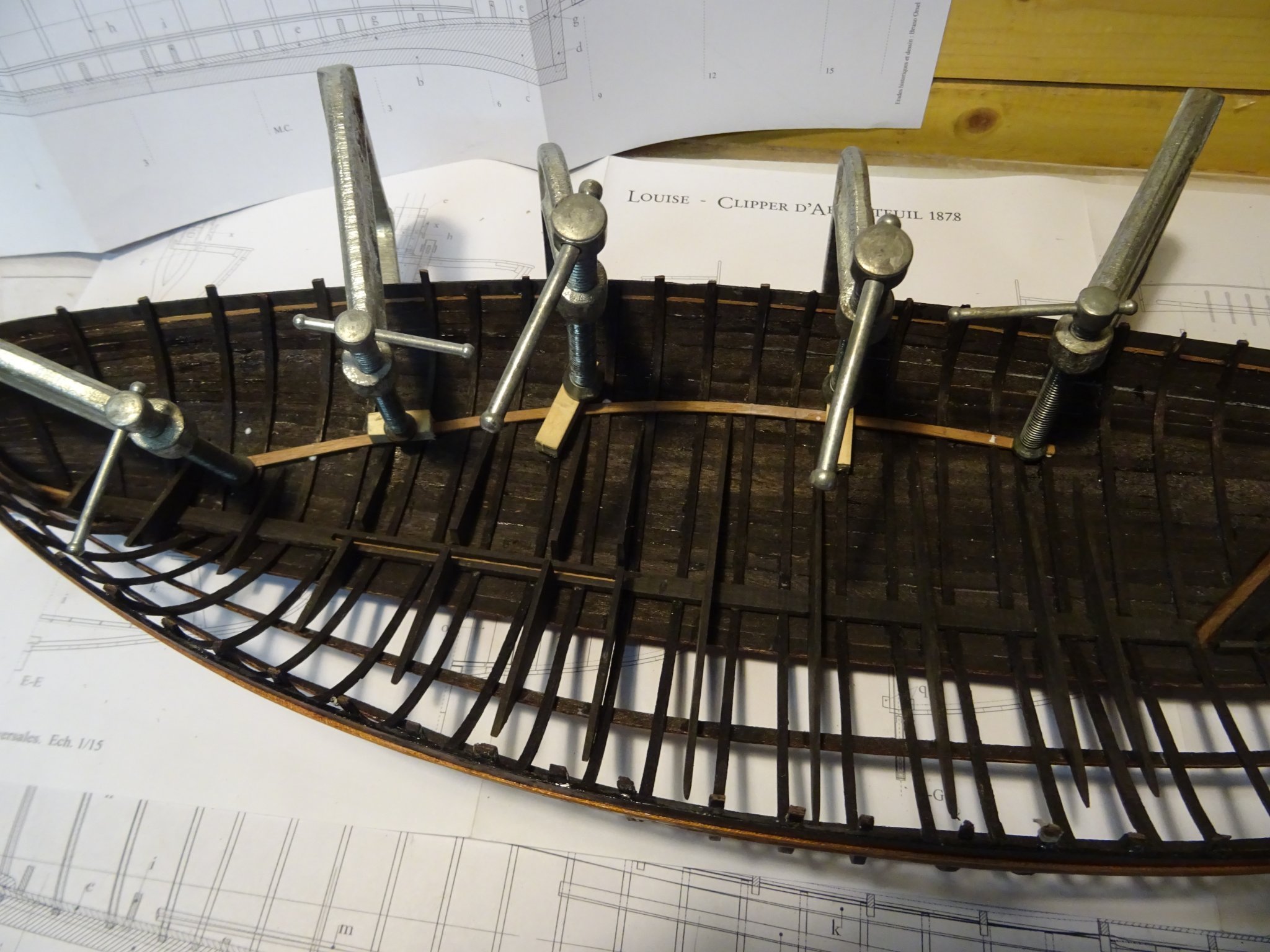
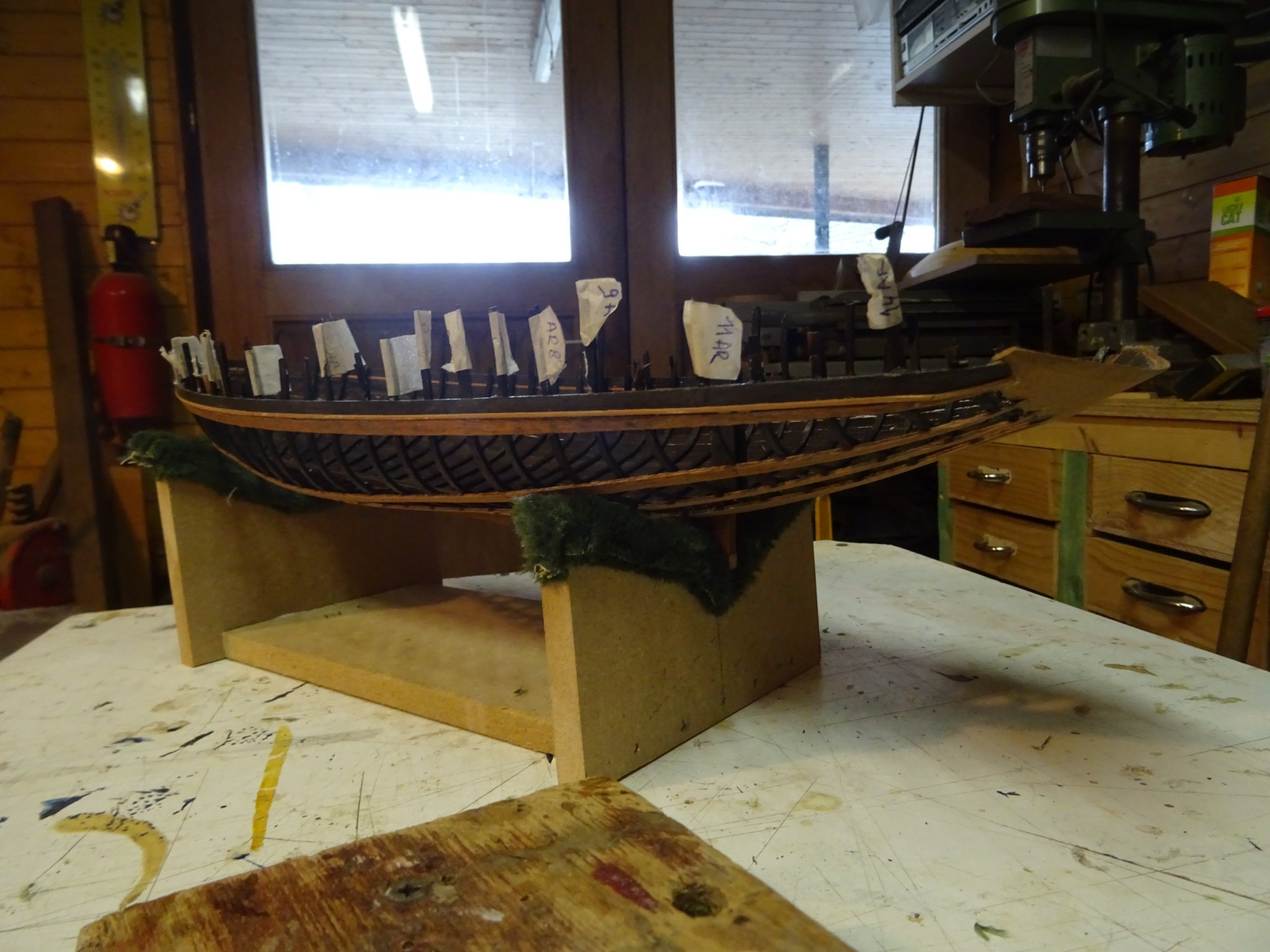
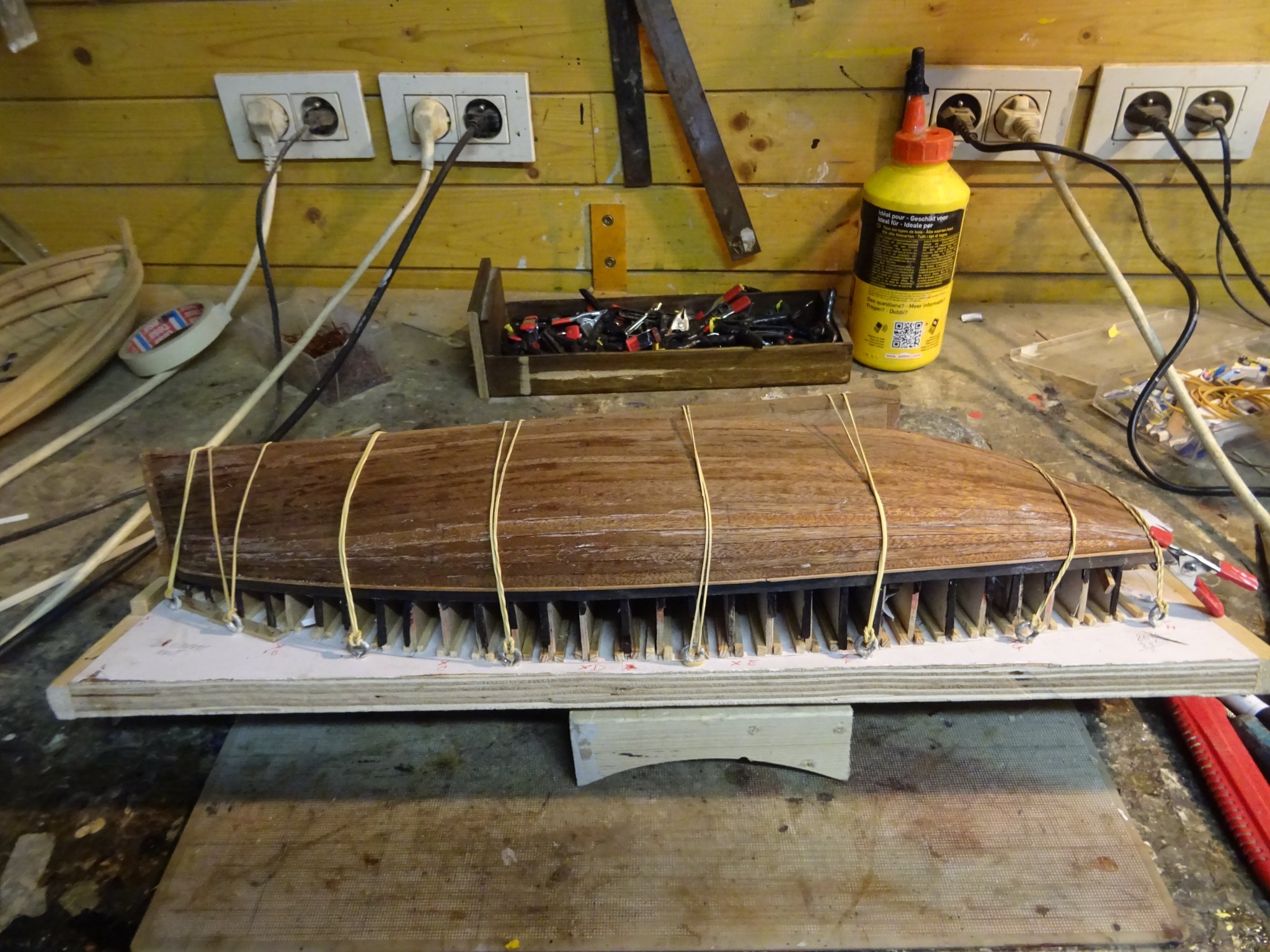
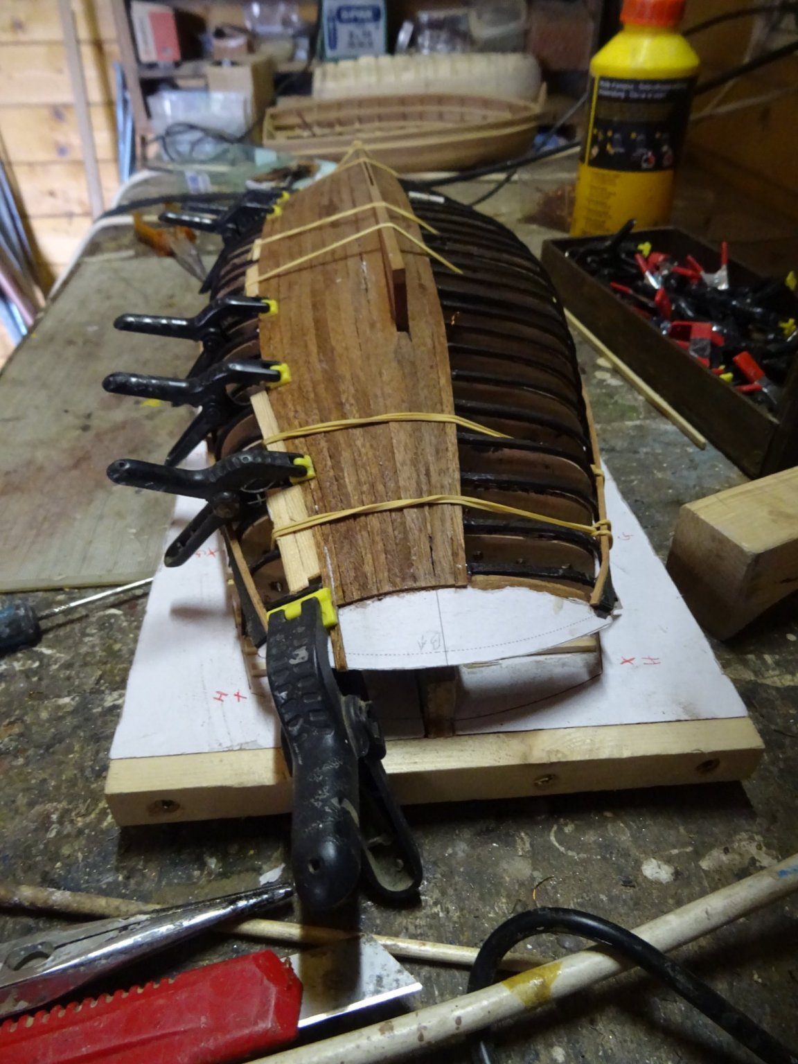
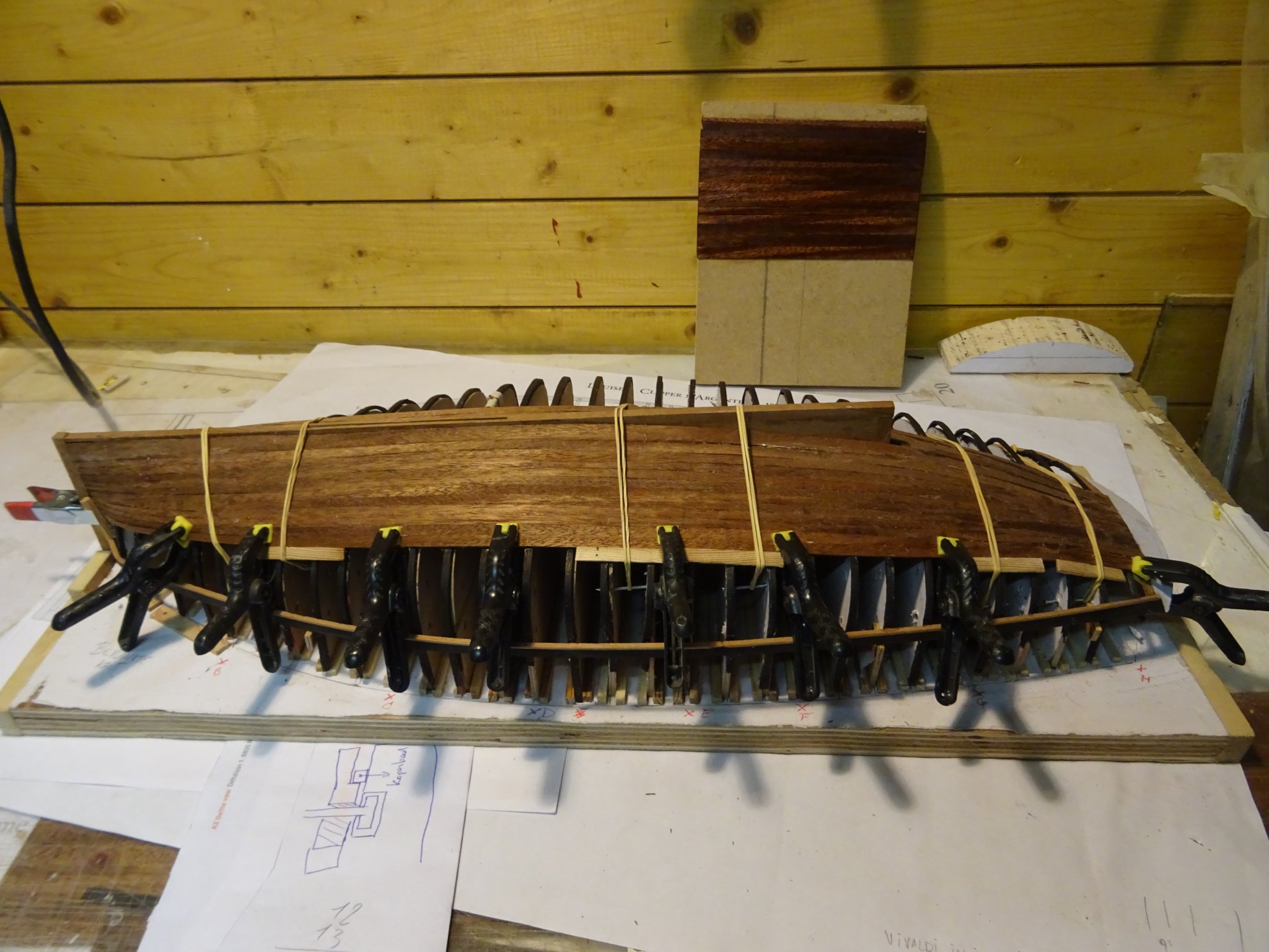
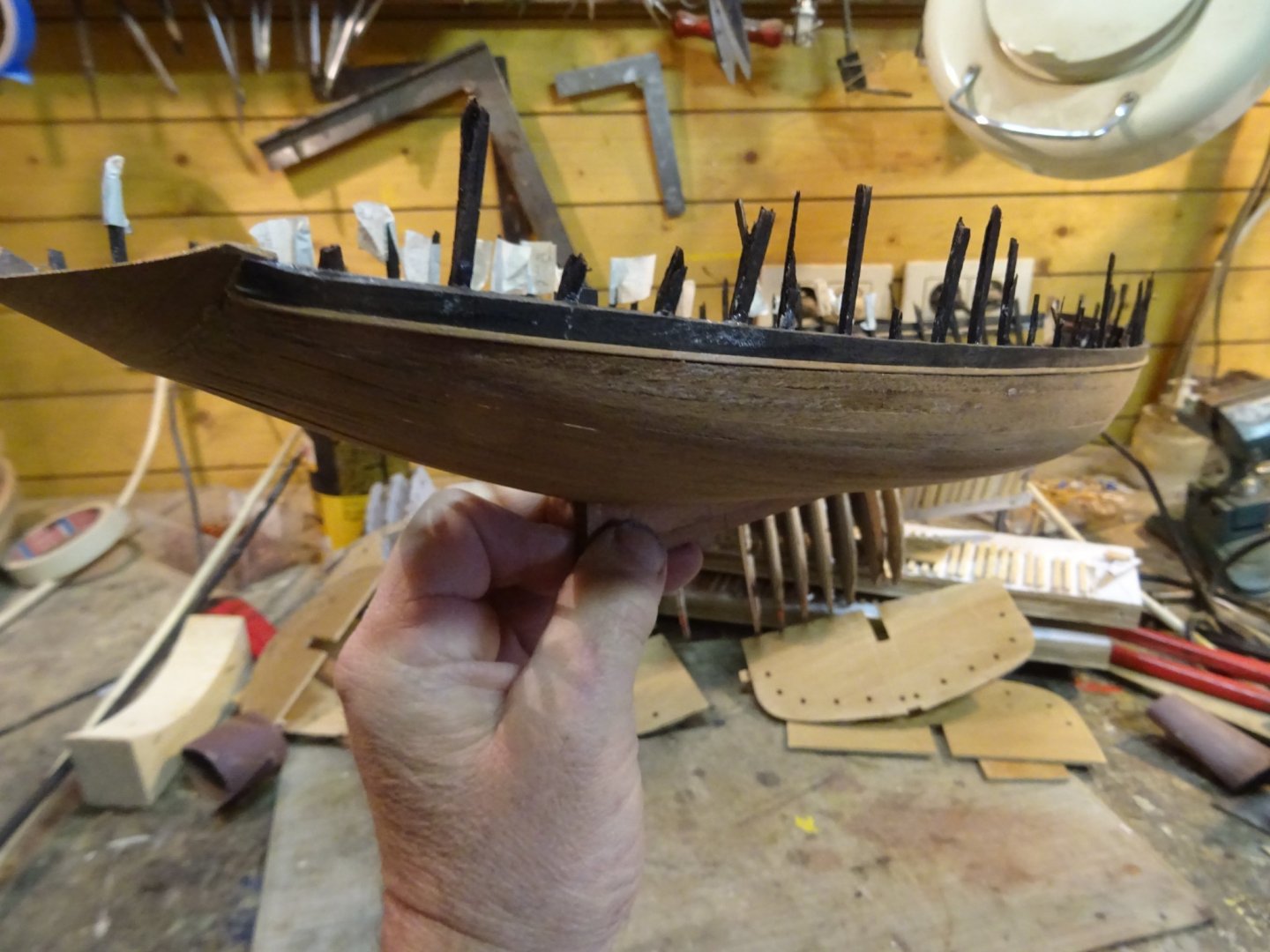
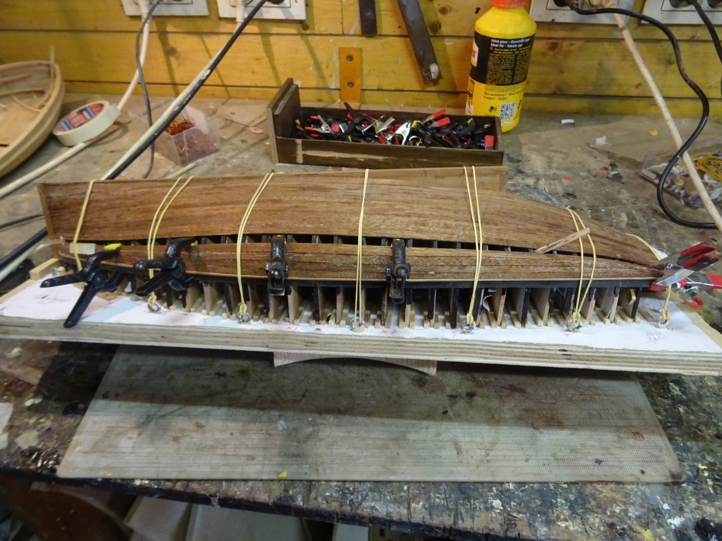
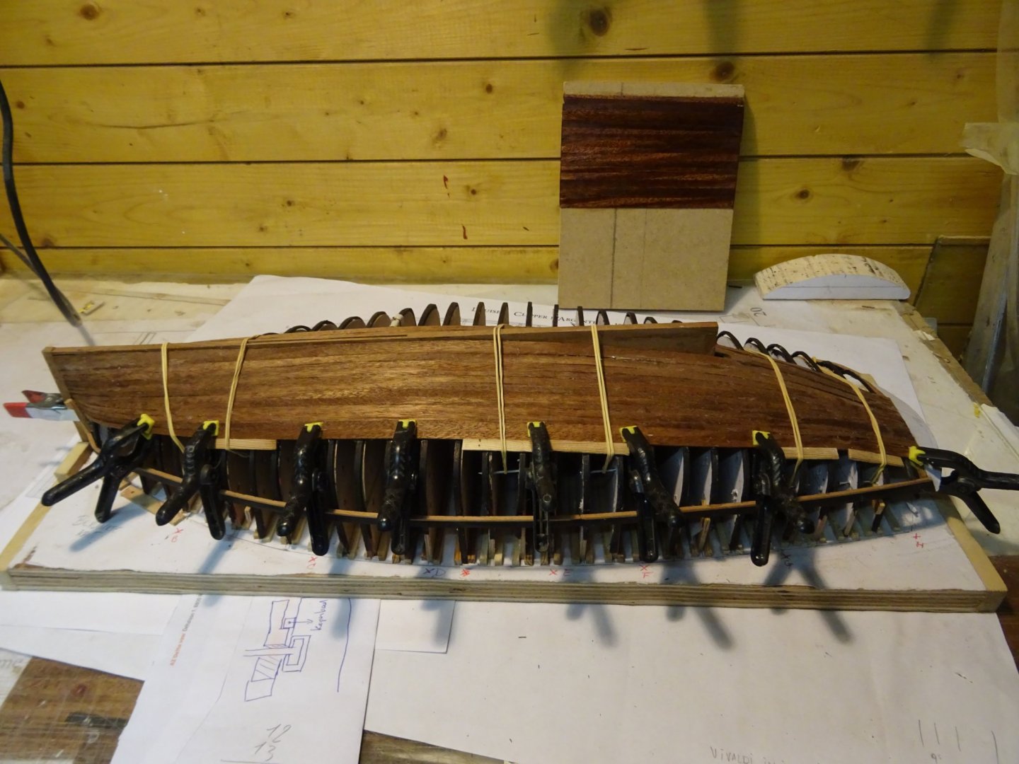
Only one more strake to place. The last one will probably be the hardest one because this one has to fit at both sides. No need to calculate any more, I can measure the width immediately between the two planks. The last plank fits surprisingly well. Time to tackle the portside. I don't know if you remember that I intend to place only a couple strakes at the port side to give an clear view of the inside of the hull after the example of the model of Mr. Orsel. I start with the strake just below the wale. Now I divide the space between the two extreme strakes by three and that gives me the location of the only two planks which will be added. Planking is completed: Thank you very much for reading this log, for your likes and for all your encouraging reactions. Till next week!


- 153 replies
-
- 9
-
-
-
- Ancre
- Bruno Orsel
- (and 2 more)
-
They look good, Mark.
-
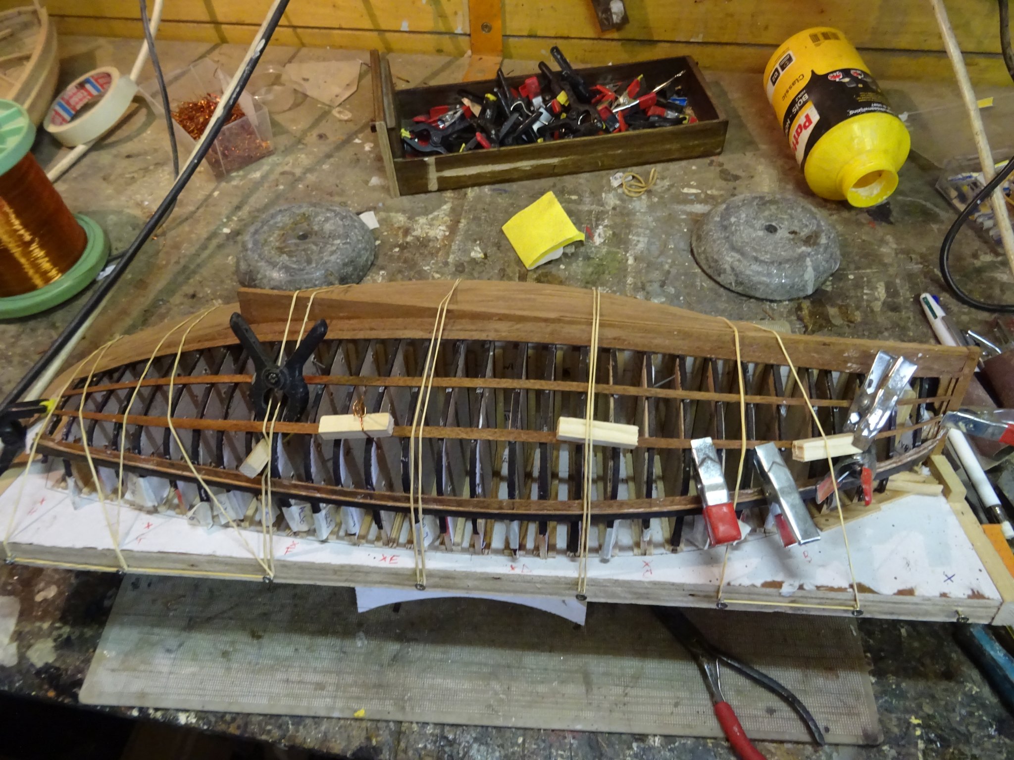
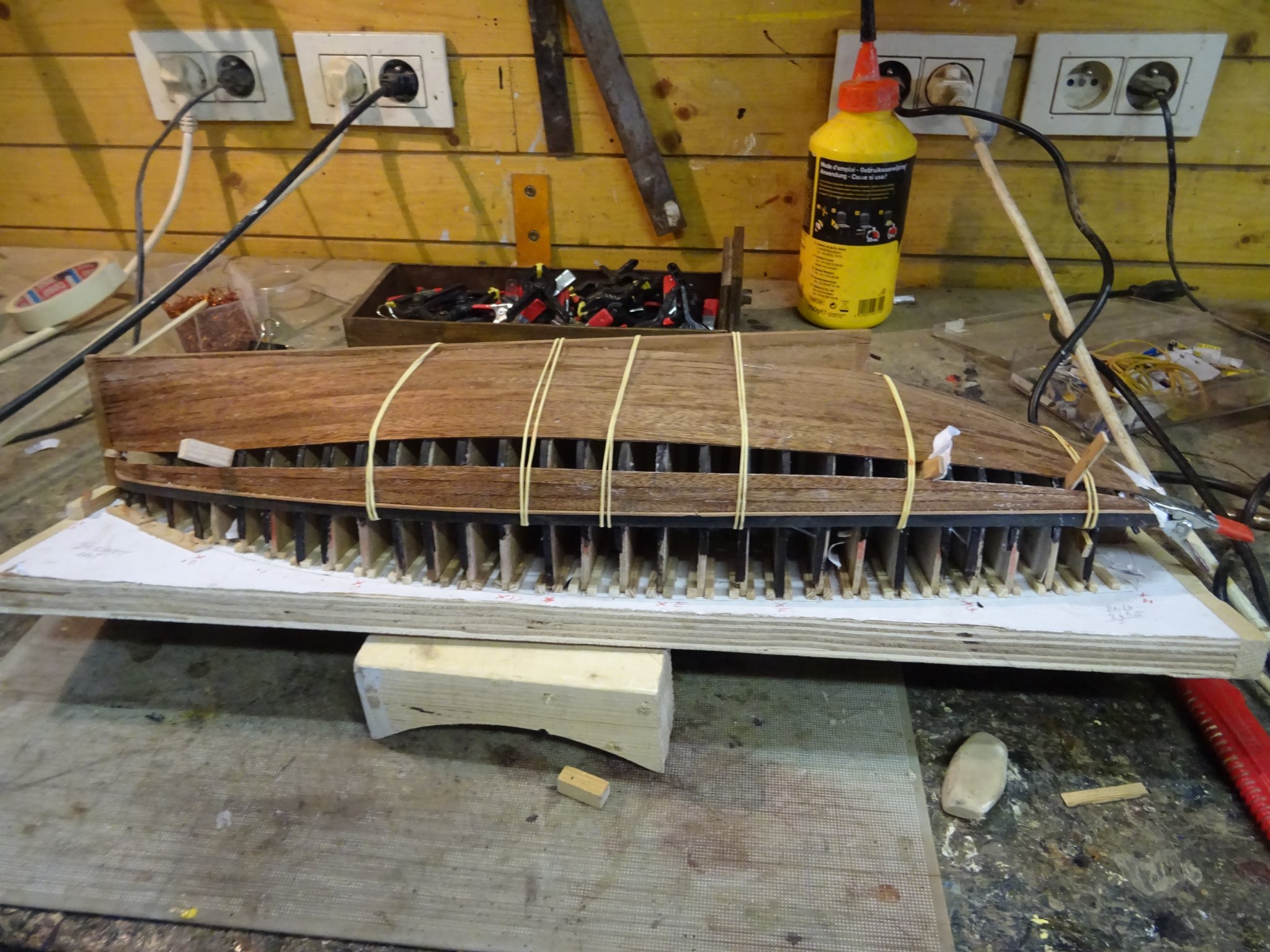
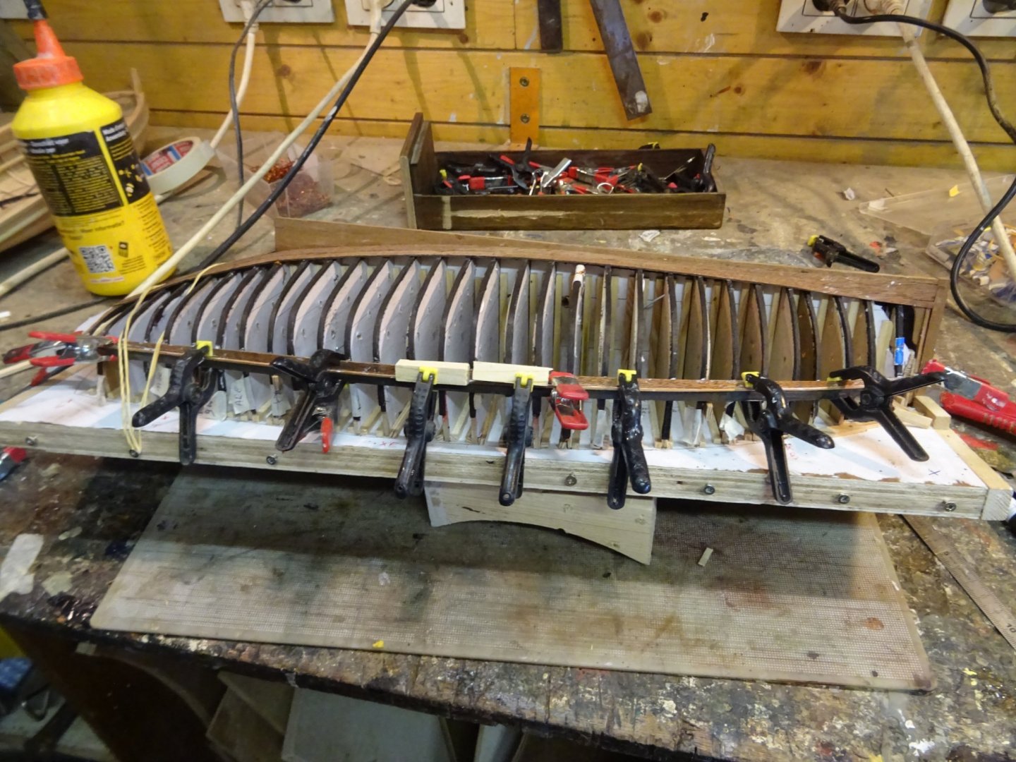
I'm afraid it is getting a bit monotonous, but also this week I can show nothing but pictures of the planks. From now on I alternately place a plank at the top and one at the bottom. I hope to close the gap in my next post. Thank you very much for reading this log, for your likes and for all your interesting reactions. Till next week!


- 153 replies
-
- 8
-
-
- Ancre
- Bruno Orsel
- (and 2 more)
-
I think wood carving like Mark does is more authentic and closer to contemporary models.
-
Congratulations, Neil. That is a very realistic model of Orca. A great job!
-
Indeed a nice tool, Patrick. All credit goes to Mr Orsel, it took also a while for my poor mind to understand it on the Marine & Modélisme d'Arsenal forum.
- 153 replies
-
- 1
-
-
- Ancre
- Bruno Orsel
- (and 2 more)
-
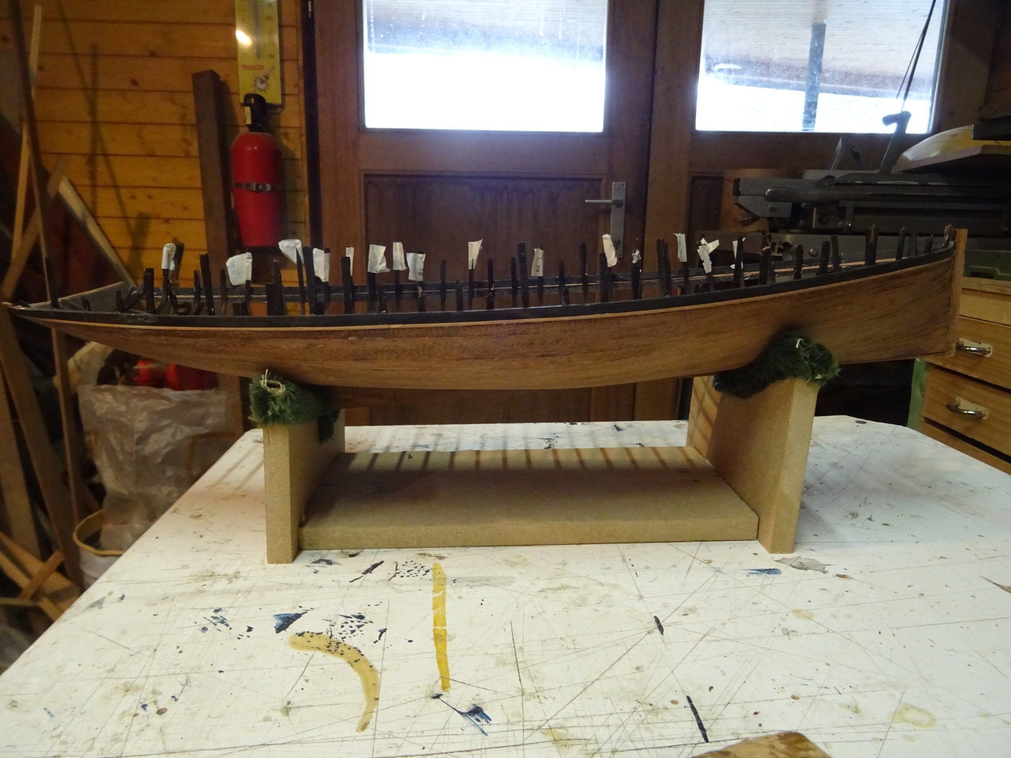
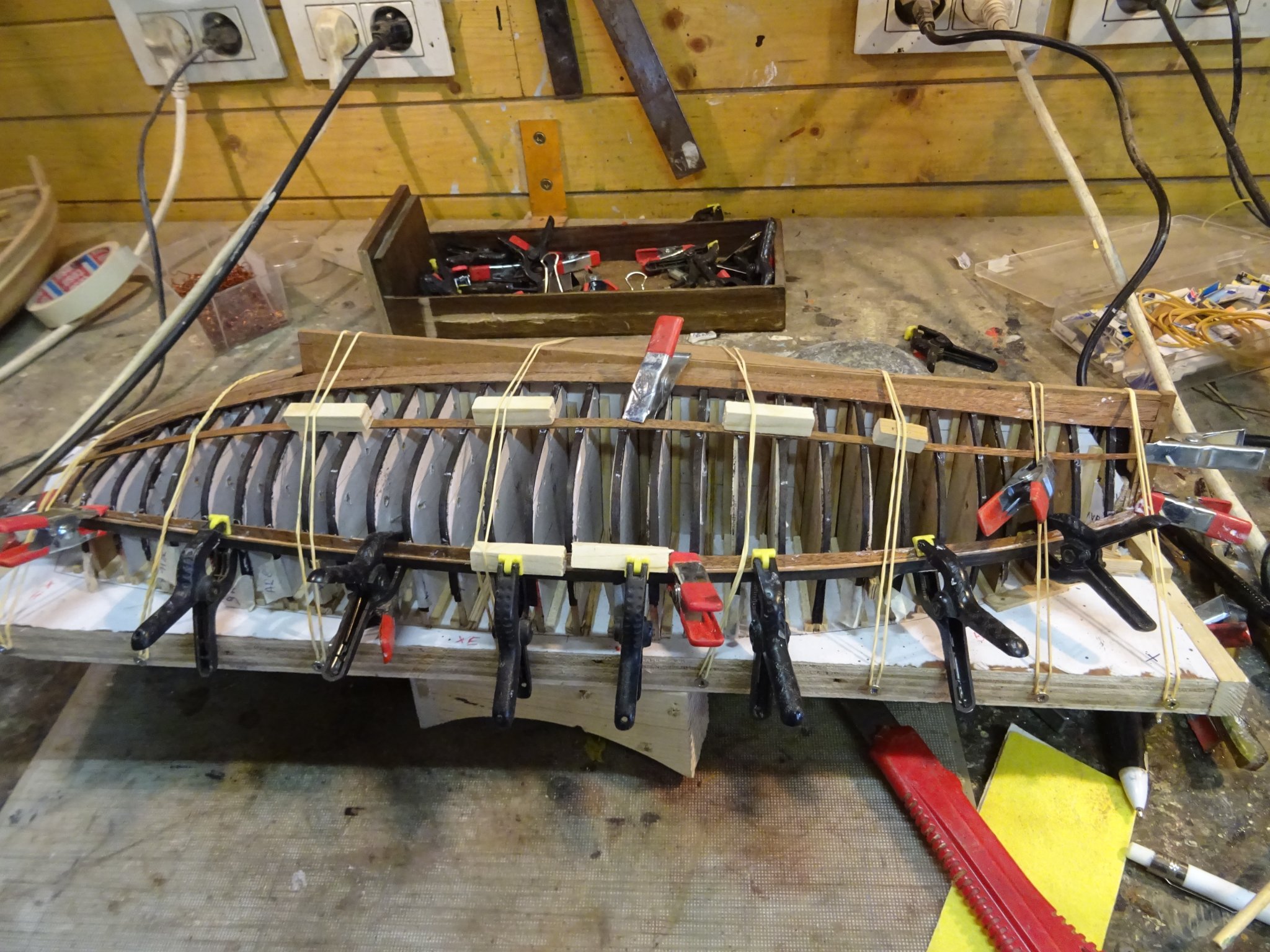
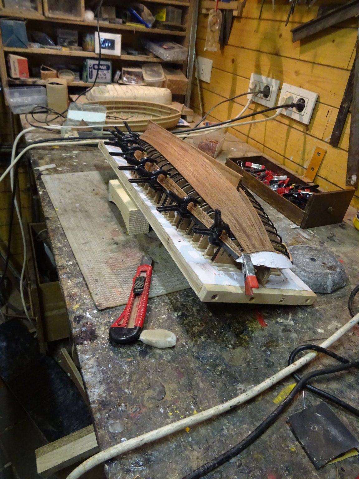
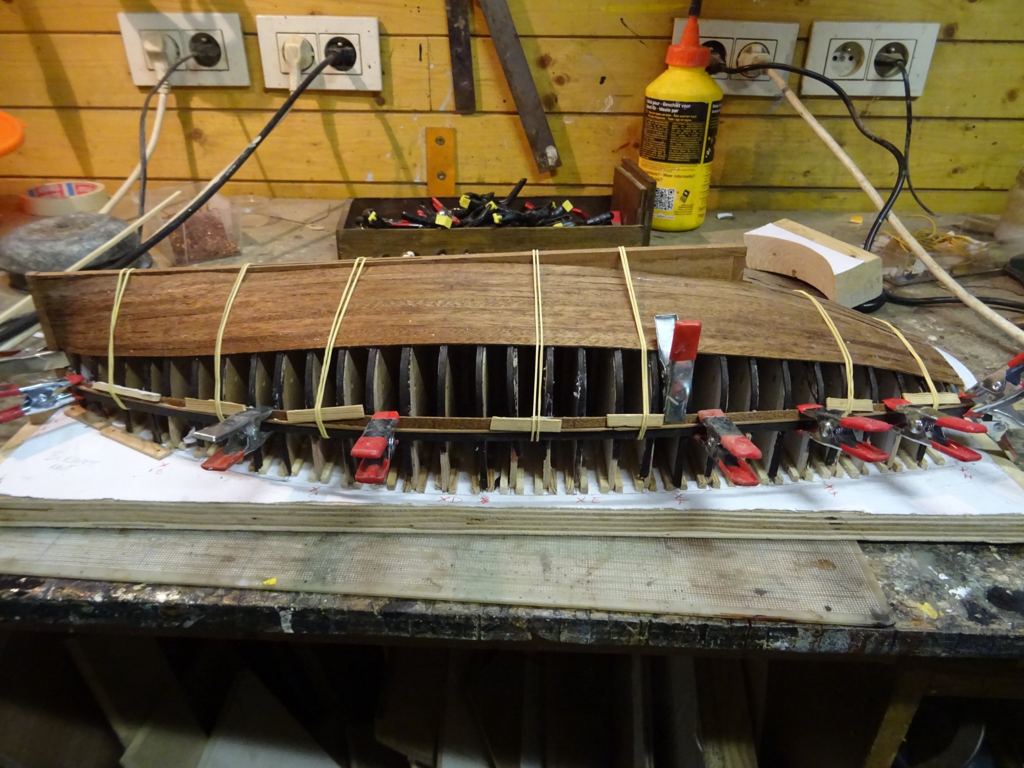
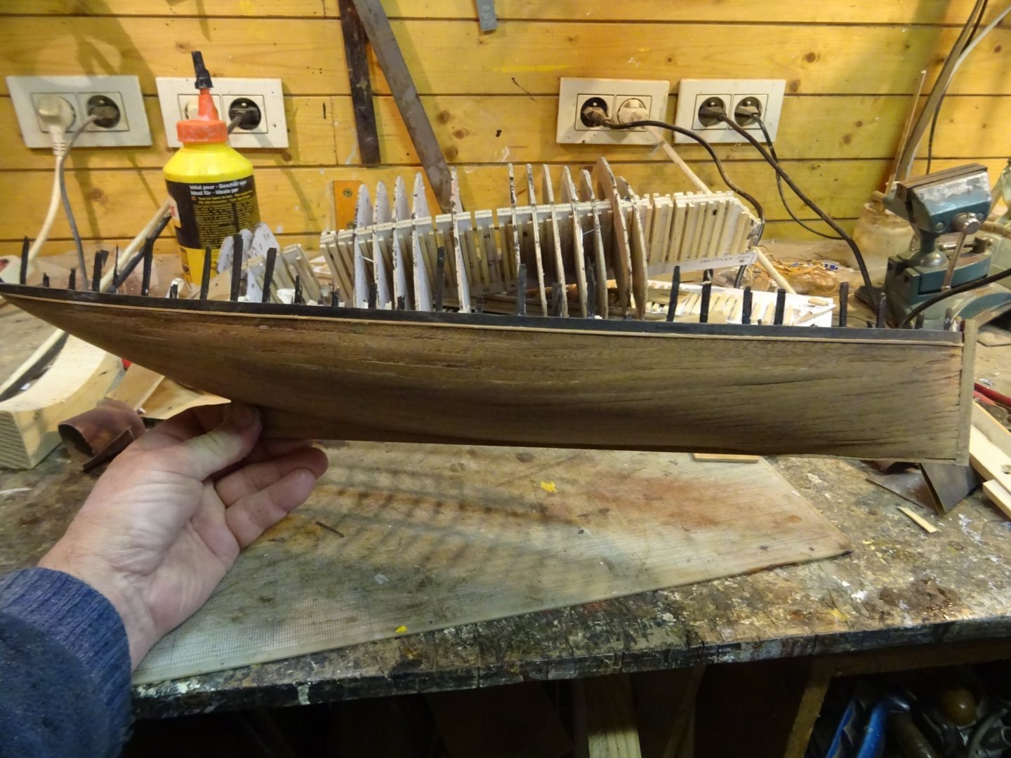
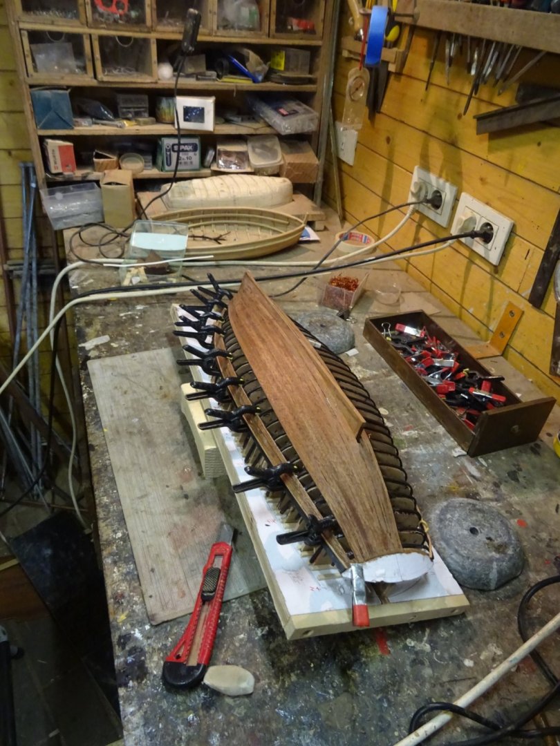
Still busy with planking. The hull is slowly revealing its elegant lines. To say it in Wefalck's words: she begins to look like boat, rather than the carcass of a dead animal Time to reevaluate and recalculate the strake shapes. Thank you very much for reading this log, for your likes and for your encouraging and inspiring comments. Till next week!


- 153 replies
-
- 8
-
-
- Ancre
- Bruno Orsel
- (and 2 more)
-
Jim and Yves, thank you very much for your encouraging comments!
- 153 replies
-
- 1
-
-
- Ancre
- Bruno Orsel
- (and 2 more)
-
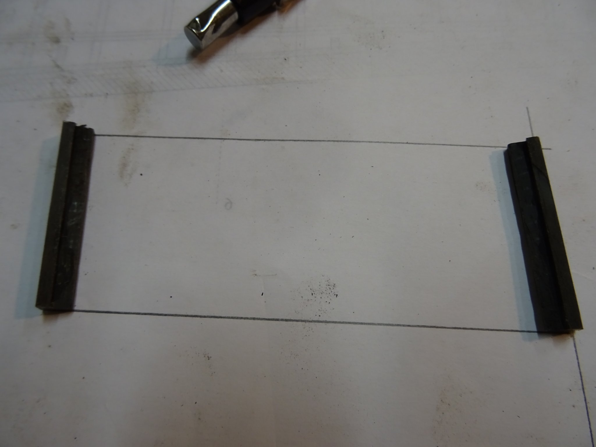
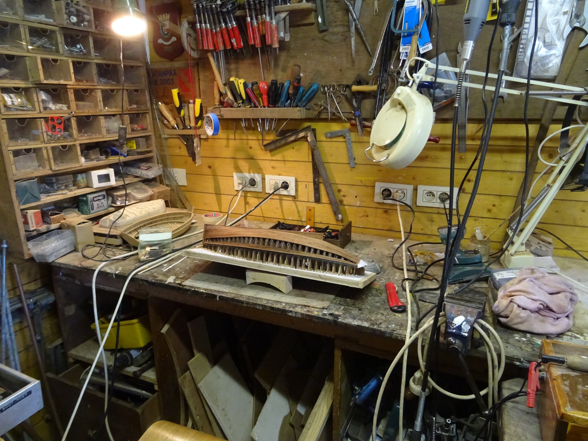
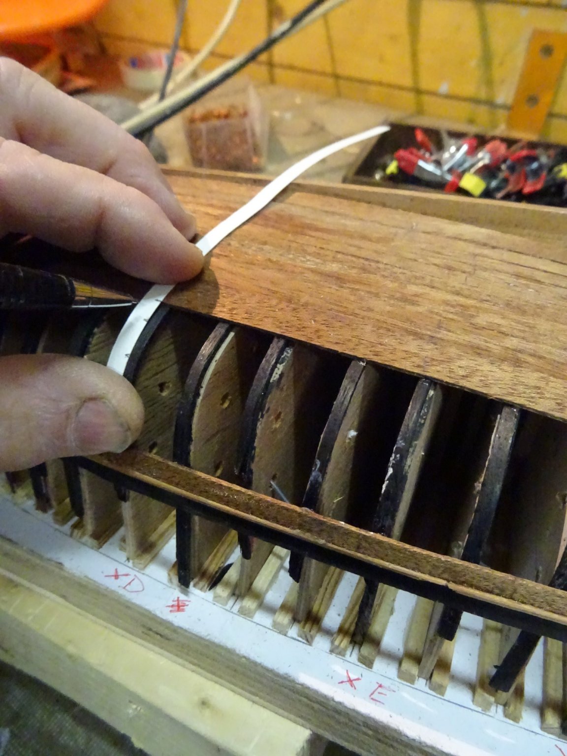
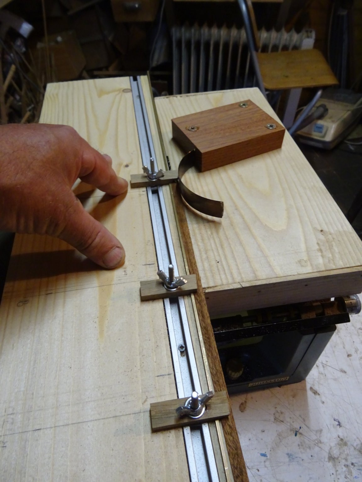
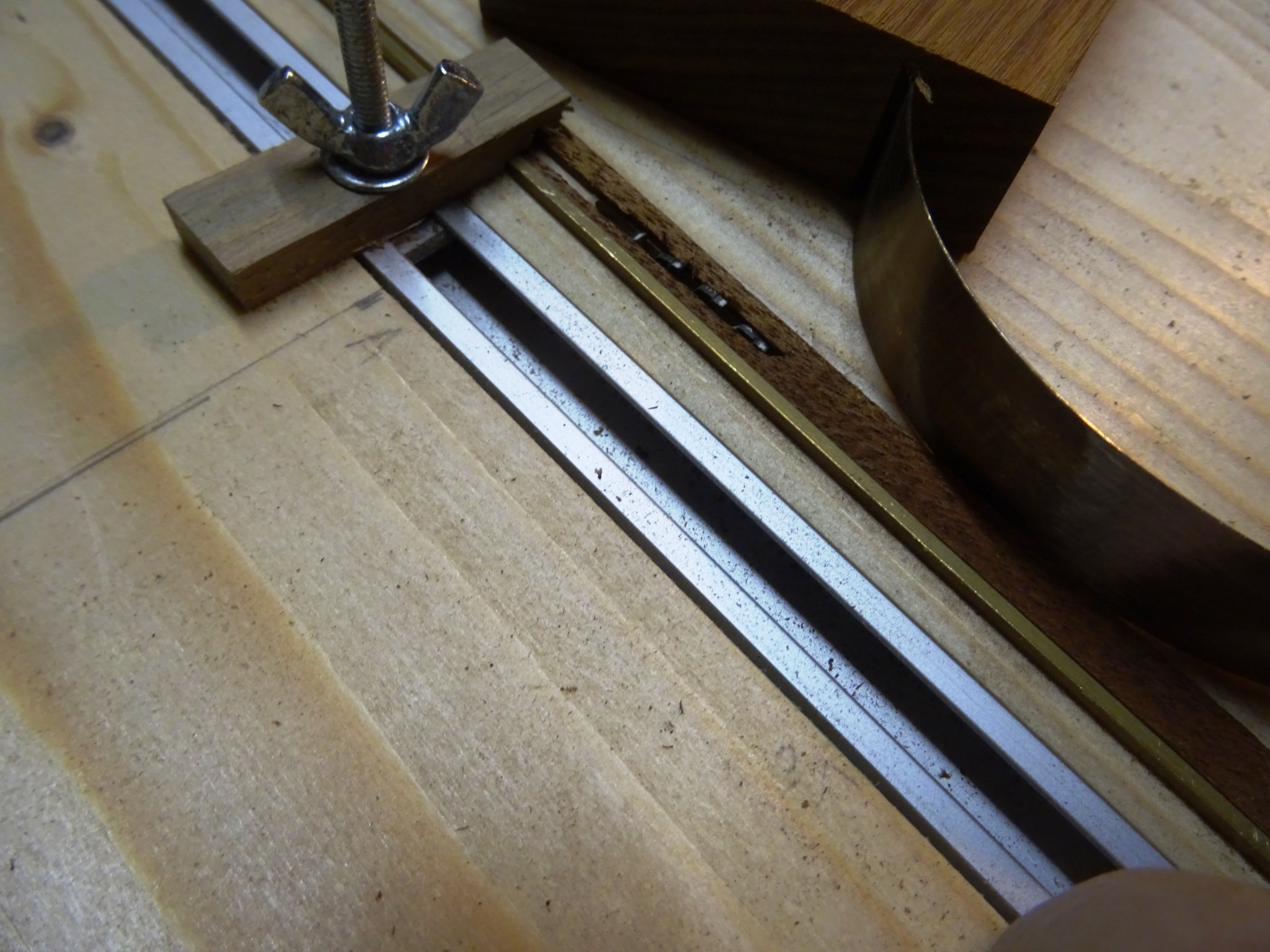
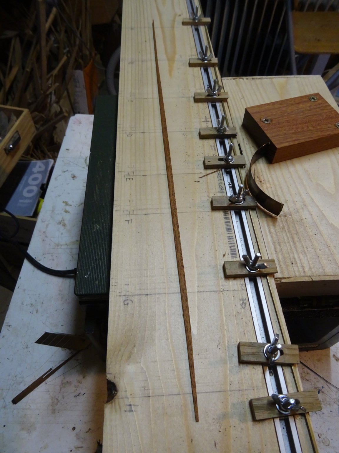
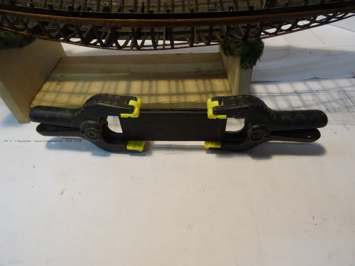
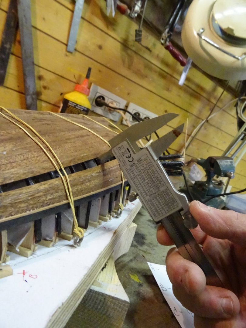
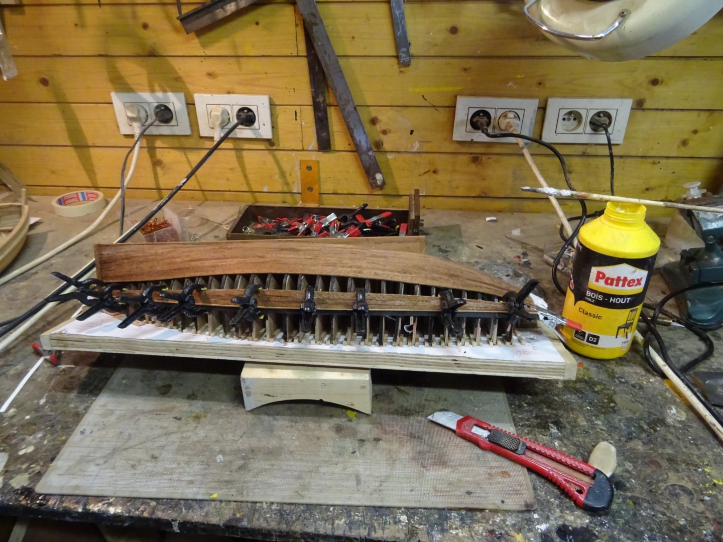
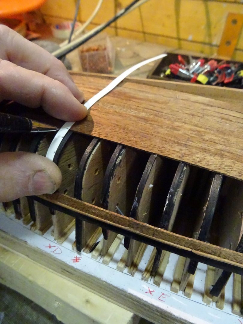
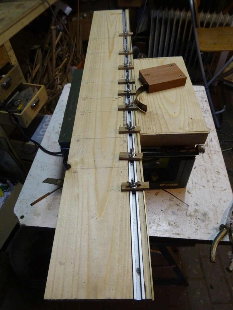
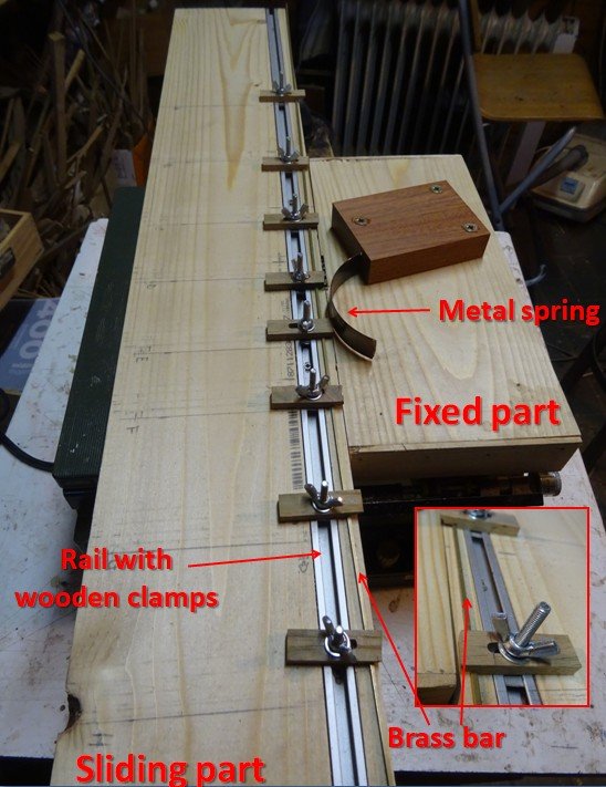
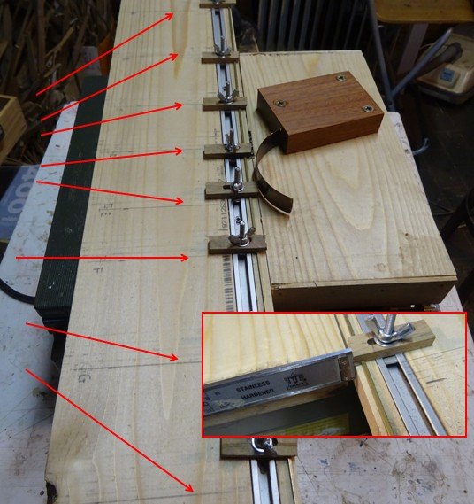
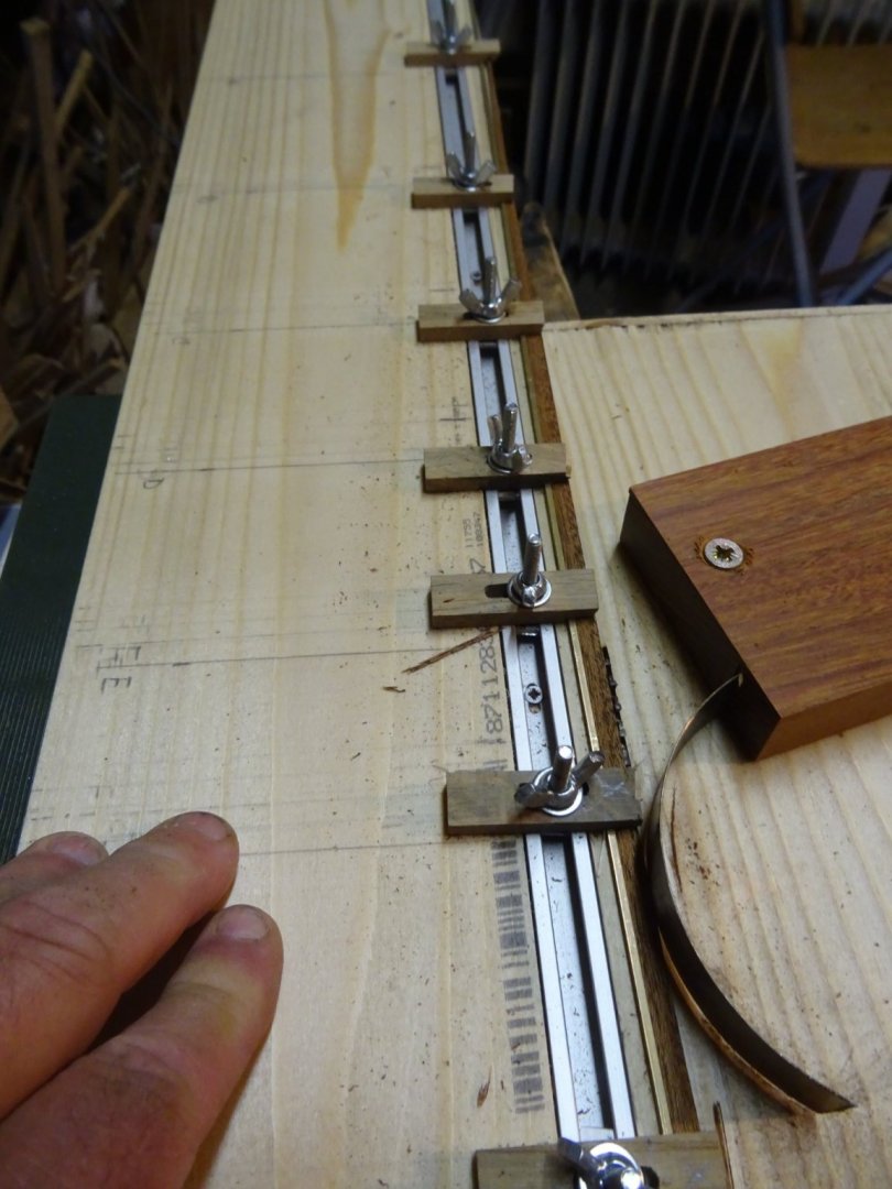
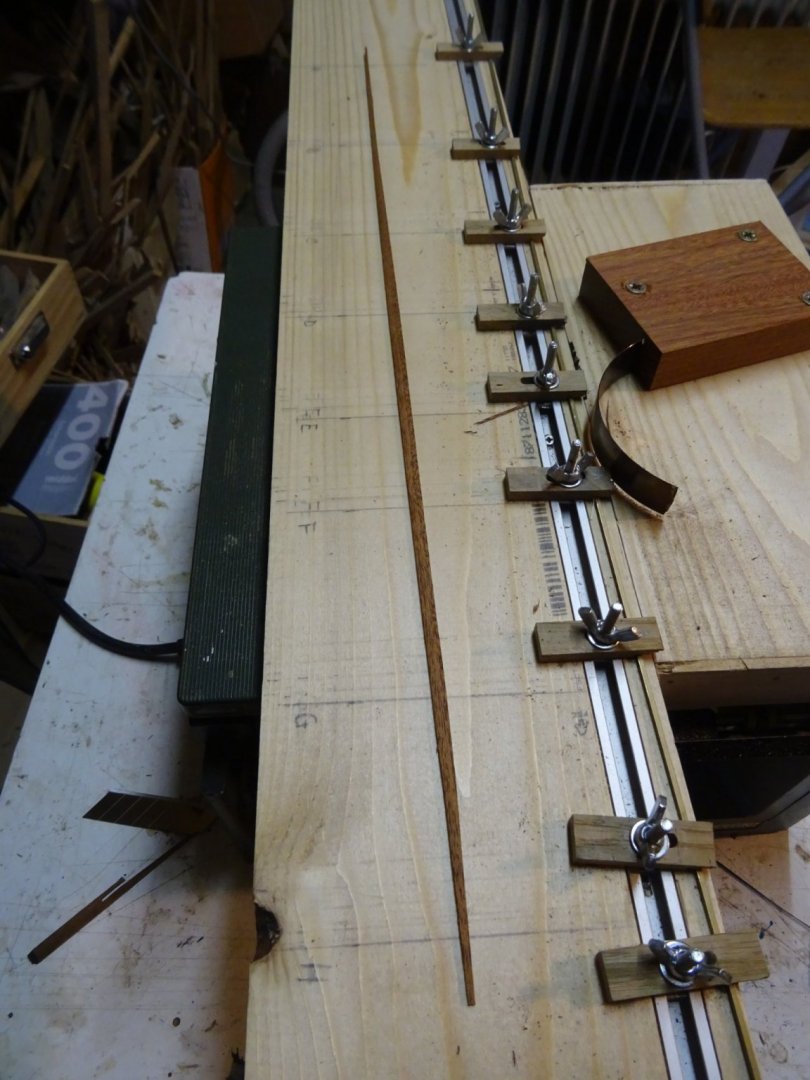
My plank job is a lot easier than yours in your fishermen's launch and your yawl longboat. The hull is straight throughout and the planking does not run over the dead wood. My planks are also less than one and a half mm thick, so they are very easy to press against each other without having to use all kinds of difficult bending techniques. To cut the planks I use on my table saw a tool copied from Mr Bruno Orsel's construction log on the French forum 'Marine & Modélisme d'Arsenal'. It consists of a fixed and a sliding part. The fixed part has a metal spring. A (curtain) rail is integrated in the sliding part. Wooden clamps can be slided over this rail and can be secured with a wing nut. The clamps hold a long brass bar (squared shaped 2mm x 2mm). How does it work now? I mark the spacings of the frames where I measured the strake subdivision (needs to be redone for each strake as they vary slightly in length) . On these marks I fix the brass bar with the aid of a caliper at a distance equal to the relevant strake width from the edge of the slide (see inset). I now place the plank to be sawn in the slide against the brass bar ... ...and slide it through the saw. The spring pushes the plank tight against the brass bar and my plank is cut nicely curved into shape. Not easy to explain this clearly. I hope that the pictures are more or less self explaining.


- 153 replies
-
- 7
-
-
- Ancre
- Bruno Orsel
- (and 2 more)
-
HMS Enterprise by AlexBaranov - 1:36
G.L. replied to AlexBaranov's topic in - Build logs for subjects built 1751 - 1800
Splendid, Alex, and such a details!