
Kenchington
-
Posts
727 -
Joined
-
Last visited
Content Type
Profiles
Forums
Gallery
Events
Everything posted by Kenchington
-
 Then I can welcome an old shipmate to MSW! You and I probably worked side by side in the wet lab, all those years ago. I wasn't on any squid cruises and had no contact with DFO's squid scientists at that time, though I did brush up against the people at Dalhousie, who got the squid to spawn in the Aquatron tank. (Maybe ones your brought in live?) And I do remember the Hammond's hopper full of tons and tons of the oily beasts. As you likely know, they have occasional exceptional years and one came in the early '80s. Trevor
 -
It was a long time ago but I think he was Fred. I wonder whether you were aboard for any of my trips. I think my first would have been winter 1980 and the last probably in '82. I was chasing redfish in those days. Trevor
-
Michael: I'm impressed! I could not have handled hydrographic surveys, let alone on-board model building after a day in those survey launches. Hammond Innes was probably the finest, most successful distant-water wetfish trawler the British ever built -- as well as almost the last of them. I still have soft spot for her in my heart. But as a research trawler, I have to agree: She was a bitch. In a sick way (pun intended), I'm glad you had the same trouble I did. I got on well with the Chief Engineer (both of us being Limeys) and he insisted that he knew how to ballast a trawler. I was never sure that he understood the difference between a ship with a hold full of ice and fish, versus one with only scientific gear and a lot of ballast down there. Even so, Prince was worse, once she was used outside the Gulf. And the Templeman/Needler pair, amongst their other problems, had the accommodation for the scientific party up forward, so they gave us little rest. Then again, the Australians, who could have had the Hammond's sister, C.S. Forester, bought the much-smaller, French Soela instead. She was a lot of fun in a 75-knot gale on the South Tasman Rise, around 49° South. Trevor
-
I do recommend McKee's booklet on clinker construction -- and no less after re-reading it now than I did from memory of a first reading decades ago. I have his "Working Boats" too, though I still prefer March's "Inshore Craft of Britain". Still, they are more complementary than in competition, for us as readers. Trevor
-
It is well known in the feline universe that humans build small, intricately complex structures so that cats have something to knock to the floor and bat around. Why else would people stop playing with their pets and fuss over all those tiny pieces of wood and string? Trevor
-
Moving ahead with planning for the model: McKee’s booklet gives full instructions for building his card model but deals more generally with the full-size boat. It does not include the plans for that (though the essentials can be reconstructed from the printed card), while the information it does give s scattered through the text, figures and glossary. So an initial step has to be a read-through and extraction of details, starting with what, in the modelling world, could be called a “parts list”. I’ll accompany that with such of the scantlings as McKee specified – those for full-size construction given here. Throughout, I will use his terminology, though he emphasized how variable the accepted usage was across the length and breadth of Britain, let alone further afield. (At least, I will use McKee’s version except for his choice of the ugly and confusing “stempost” for the stem.) So: BACKBONE Keel: Sided 2 inches, moulded 2 ½ inches Hog: Sided 5 inches, moulded 2 ½ inches Stem: Sided 2 inches Apron: Sided 5 inches Deadwood Sternpost Wedge Transom: 1 1/8 inches thick SKIN Planks (10 strakes per side: Strake diagram provided in booklet): 3/8 inch thick Gunwales Fillers (where needed between gunwale and sheerstrake): Moulded ½ inch Timbers (13 or 14 full, 3 pairs of cants): Sided ¾ inch, moulded ½ inch MOULDS (2 for full-size, 3 for card model) INTERNAL FITTINGS Risings (1 pair) Breasthook Quarter knees (1 pair) Plates and toe cleats for crutches Thwarts (2) Thwart knees (2 per thwart) Thwart pillars (1 per thwart), stepped in morticed blocks on hog Stern bench Side benches Bottom boards, on skirting rails Sternsheets Ringbolt through apron and stem (for painter) EXTERNAL FITTINGS Rubbers (1 per side) Jack Nichols (1 pair) Bilge rails (1 per side) Landlists (along lands of bottom strakes) Brass strip from stemhead to around transom heel (Might need ones on bilge rails too) Fastenings are not listed here, as they are replaced by glue in a model. However, the clenched nails should be noticeable internally, even if painted over. If those are represented in a model, their pitch along the strake laps should be 6 times the plank thickness, so a nail every 2 ¼ inches. Every third nail passes through a timber as well as the lapped strakes. At 1:12 scale, 3/8 planks equate to 1/32 basswood, which is easily found. (My local Great Hobbies store carries ModelExpo sheets.) The transom will need to be thinned down from 1/8 basswood, which should also serve for the moulds. The timbers can be worked out of 1/16 strip. Most of the fittings can probably be made out of bits and pieces in my scrap pile. I have a mind to make the backbone (excluding the transom) from cherry, to make it a bit more robust than it would be in basswood, especially as it will need a lot of shaping for the rabbets and bearding. A sheet of 1/4 inch should give me more than enough material. Trevor
-
Looking very nice! Trevor
-
That's an amazing model, Michael -- and a remarkable story! What position did you have on Baffin and the Matthew that gave you time for model building? I remember both of them, when alongside the BIO wharf, though (not working on the hydrography side of the Institute) I was never aboard either. My time at sea was on the research trawlers: Navicula, Lady Hammond, Prince, later Templeman, Needler and Teleost. Trevor
-
Don't feel bad! English and Nautical English can feel like different languages sometimes. Then there's the English of Shakespeare and the King James bible (neither much older than the Livro) which would be misunderstood today, were it not that so many of us were exposed to those as children. I doubt that Portuguese is any simpler! Trevor
- 49 replies
-
- 1
-

-
- Wildmanden
- Turesen
- (and 1 more)
-
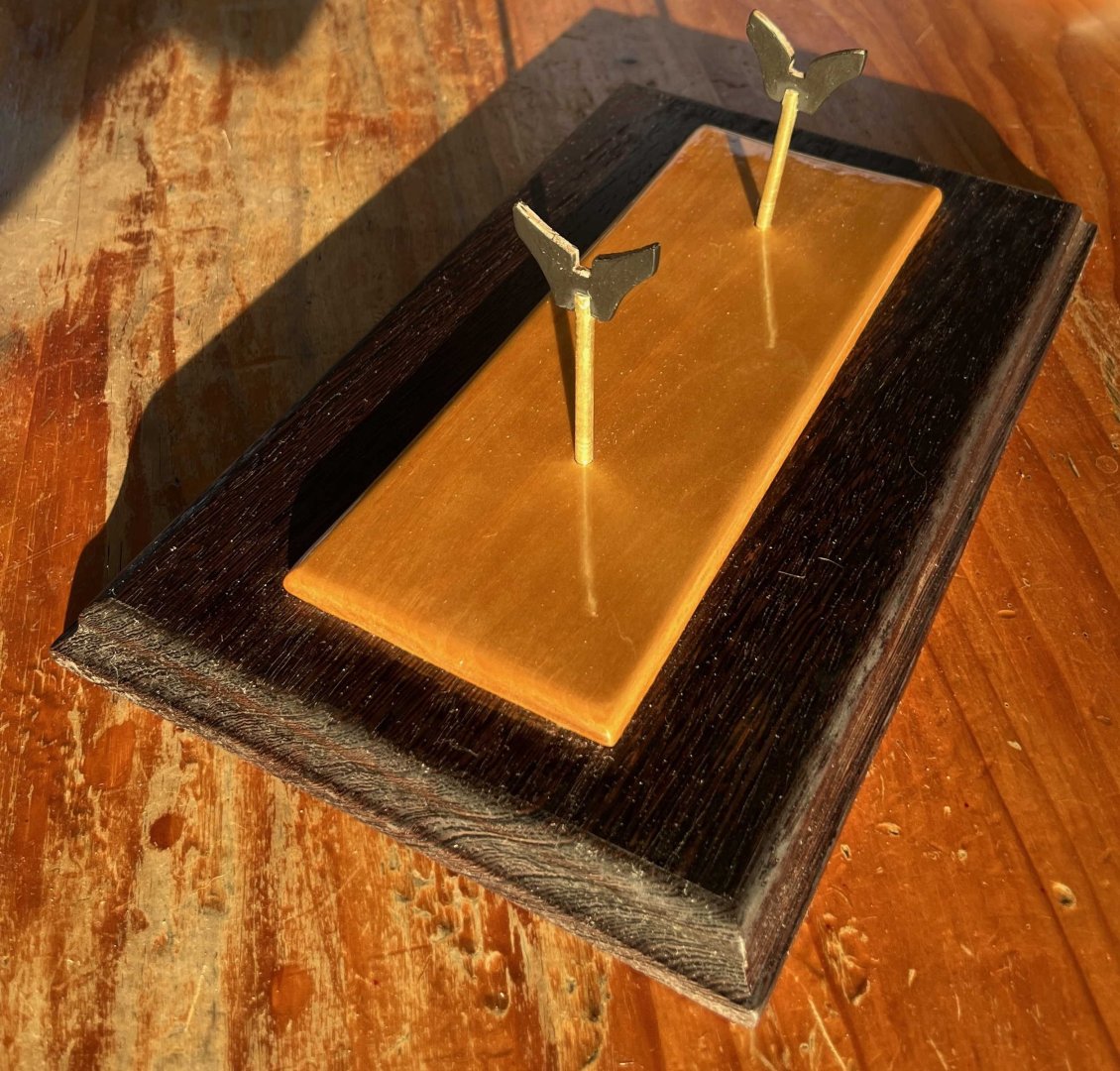
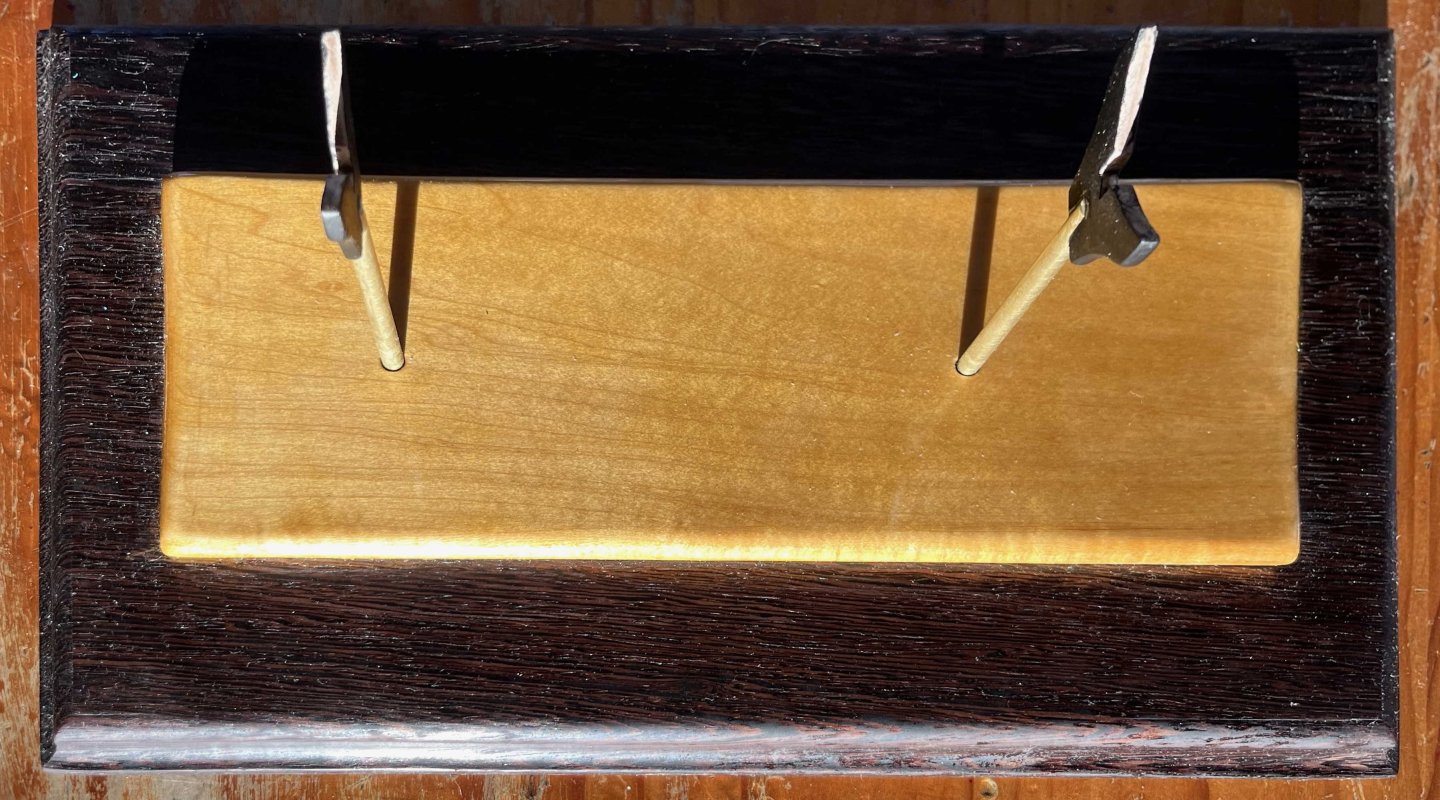
While pondering how best to fix the transom problem, I have pushed ahead with the model's stand. That's way out of sequence but my heavy tools live in my island cottage and, at this time of year (water too cold to paddle over but not yet frozen hard enough to walk on), my access is limited to periods when low tide falls within the short December daylight. Worse, I have to lug dust producing tools out onto the patio, as my only way to disperse dust is natural ventilation by the wind, and that confines me to rare, warm afternoons. I have to take advantage of the limited opportunities as they arise. My dory build forcibly taught me a lesson that I know many MSW members had learnt before me: While a beautiful stand can never save a disappointing model, an ugly one can ruin the visual impression of a successful build. I wanted to do better with my pram and so combined an idea I picked off another member's build log (transparent acrylic posts, in place of kit-supplied dowel) with my own contribution: A hardwood plinth under the kit's basswood baseboard. I liked the result and aimed for the same concept with this base for the Muscongus Bay boat. However, my pram is clear-finished, so the basswood base is solid colour (white) and the plinth a rich red of oiled jatoba. My sloop will be painted, so I wanted golden grain showing in the basswood base. I have given that multiple coats of marine varnish, as I would the brightwork on my full-size boat. That seemed to call for a much darker plinth and I picked up an offcut of wenge (from Zaire) at my local supplier. That only needed very slight squaring-up with a plane, then an ogive cut in the sides on the router table, following by a bit of hand sanding. I got into some trouble gluing the basswood to the wenge. I did not allow for warping of the basswood when wetted with yellow glue, so did not weigh down its corners while the glue set. Also, I should have masked the wenge to protect it from penetration by surplus glue oozing out from under the basswood. Easy enough to sand off that excess but the glue-impacted wenge does not take up tung oil to match the unaffected surface. Another time, I will mask areas that might get a glue coating. Still, the defects won't be noticed in the end. With a drill press to ensure vertical holes, I extended the laser-cut holes in the basswood down into the wenge, thus providing a better grip for the uprights, while being careful that both holes were equally deep. That disturbance called for a final coat of varnish over the top of the basswood, without touching its sides or the wenge. Rather than clear acrylic, I thought the sloop would look better with brass supports, so picked up a length of rod from the hardware store. I cut the required flats (to take the kit-supplied basswood cradles) with my bench grinder -hardly needing more than a touch on the wheel– then tidied them up by hand filing. Having the full length of brass rod, I could go for longer supports than the instructions call for (so giving better display of the sloop's underbody), while preserving the 10mm difference in length that sets the correct drag to the sloop's keel and places her load waterline parallel to the base. A good go with Brasso made the posts shine. If I was as good at this hobby as I should be, I would have fabricated cradles from solid brass stock but I'm not ready for that, so used the kit-supplied ones. I wondered about brass paint but feared that that would look bad against genuine metal, so went for black instead. That should make little visual impression, once the model is perched on top. A dab of CA glue attached each cradle to its post. Last night, all that came together and gave me: {Please don't notice that the base for a little boat model has a much nicer surface finish than the kitchen table it is resting on! My wife has been after me to re-finish that table for years.} The posts are only push-fit into the base for now, as the tops of the cradles will need bevelling to match the hull, once that is ready. If they will stay in place, I will keep them removable and so be able to polish the brass from time to time. Either way, I think I have a base that will not disgrace the finished model. Now I need to get on with that, in the hope that it will not disgrace its base 😀 Trevor
-
Designed and built for a different trade. The tea was brought down the Chinese rivers in small loads. No point in waiting a long time to load in Canton, if the aim was to be the first to bring the new crop home to London. Cutty Sark and her sisters had to be big enough for speed on the voyage home and had to carry enough tea for the freight rate to cover their costs, while being small enough that the first chests stowed aboard did not lie in the hold too long before the ship weighed anchor, homeward bound. They also had to be optimized for beating to windward across the South China Sea against the monsoon -- the season of tea harvest preventing the use of favourable winds there. The Yankee clippers were built for a wider variety of tasks but especially passengers across the North Atlantic or outward to California, then grain from California to Europe, with a doubling of the Horn each way. Both trades called for larger ships. Trevor
- 101 replies
-
- 1
-

-
- Cutty Sark
- Sergal
- (and 1 more)
-
Nicely shown! But you have interpreted the martnets as brails, gathering the sail from both sides. I have supposed (perhaps wrongly) that they were like buntlines, pulling the edge of the sail to the yard across the forward face of the bunt. It would make a big difference when furling, as there would be no easy way to fist the canvas into a "skin" when it was gathered up tightly by a brail. But maybe the idea of forming a weather-tight "skin", with the rest of the sail inside, was a later development. Trevor
- 324 replies
-
- 2
-
-
- Sovereign of the Seas
- Airfix
- (and 1 more)
-
Nate's PANDORA in 3D
Kenchington replied to 3DShipWright's topic in CAD and 3D Modelling/Drafting Plans with Software
I would put it rather differently: The upper and lower surfaces of the intermediate ("filling") transoms would be parallel to the baseline (i.e. the keel). In contrast, the upper face of the deck transom has to match the camber and sheer of the deck, while the wing transom has to curve in harmony with all of the stern structure erected above it. The draught represents those shapes in orthogonal view. More generally, I think we need to bear four different things in mind. First are the general concepts of ship structures in use at a particular time and place, for hulls of a particular size and intended purpose. Understanding those needs study of textbooks, draughts and models, matched by a lot of thought. Next up are the specifics of a particular ship, as intended when her draught was laid down. If that draught or a model survives, well and good. If not, we have to fall back on interpretation from the general concepts (which can often guide interpretation of specific evidence too). Third, there is the ship as she was when launched. Steel plate and sections can be ordered to specifications, but trees come in the shapes and sizes that individuals have grown. When a shipwright picked through the pieces on hand and found a crook ideally shaped for a particular floor but a bit wider in siding than the draught called for, the excess wasn't usually trimmed off with an adze and wasted. Rather, that floor would be fitted a bit wider than intended, allowing a thinner and more economical piece somewhere else -- maybe the adjoining futtock of the next floor. Doubtless, the deviations from intentions were less in the royal dockyards than in outlying yards building fishing craft. But the draughts could not be exactly followed without a lot of waste of good (expensive) timber. Finally, there is the hull as it was at some later point in time, with all of the damage and repair that had gone on in the interim. That is not usually of much concern to model builders but it does matter very much when archaeologists examine wreck remains -- which feeds back to model building in cases (like Pandora) where the information available is partly drawn from archaeology. And so we come back to the choices of the model builder: Go for idealized generalities, a tidy representation of specific intentions or a realistic representation of messy reality? There is no one right choice! Trevor -
You have a very nice representation of the sails! There's more than one way to furl a squaresail and I'm not sure how it was done on English warships in the mid-17th Century -- though the (unreliable) Payne engraving shows the royals drawn together into a vertical, tube-like bundle ahead of the mast, which is a known technique of later decades. That source also shows the furled main course much as you have the fore course on your model, with sheets and tacks (hence the hidden clews) near the quarters of the yard. Maybe that wa show it was done but, through the 18th and well into the 19th, the clew garnets and clewlines pulled the clews up to the slings of the yard. When the sail was furled, the two clews (with their multiple blocks and general bulk) were hung outside and forward of the furled bunt of the sail. I don't know whether you should (or could) represent that but worth thinking about before you add the other sails? I can't suggest how you handle the martnets. Their elegant draping shown in the Peter Pett portrait does look lovely but would be hard to reproduce in a model and does not look very practical at sea. Trevor
- 324 replies
-
- 2
-
-
- Sovereign of the Seas
- Airfix
- (and 1 more)
-
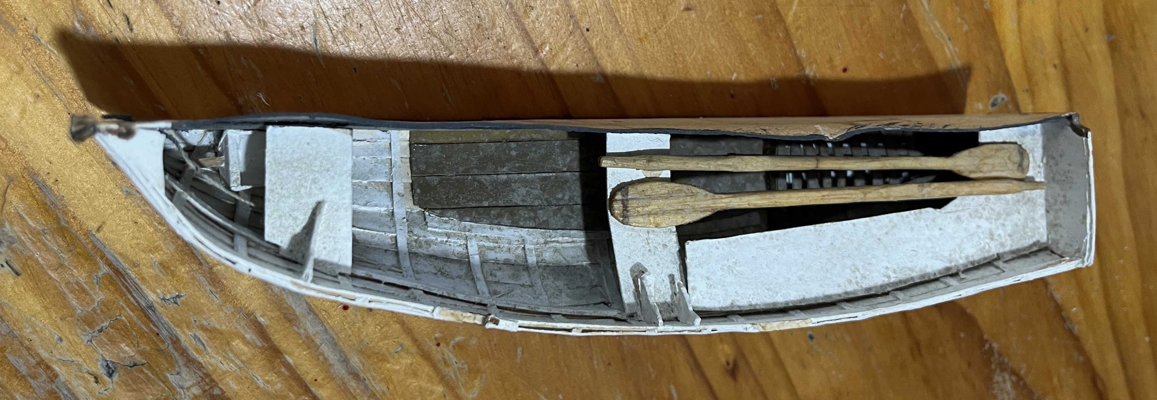
I agree that the kit-supplied rope was poor but dory beckets were made from surprisingly thick material -- at least at the start of each season. The dories were hoisted in and out of their schooner with iron hooks on the dory tackles and those wore the beckets very badly. Photographs taken aboard vessels when fishing on the banks show the deep scores that the hooks made in the rope, and the surviving fibres still had to strong enough to take the weight of the loaded dory as it was brought aboard. Take a look at the gallery for my dory. I rigged that with becket and painter, following contemporary details. Trevor
-
You have built an exceptional dory! Looking forward to seeing how you do with the pram. Trevor
-
@wefalck, your version will be an inspiration for my hoped-for model-to-be! Yours is a beautiful piece. Trevor
-
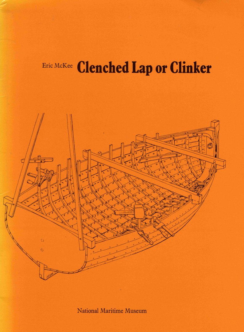
A lifetime ago, small boats in Britain and much of northwestern Europe were (almost) all clinker-built – what those of us in North America would call “lapstrake”. My own first real experience in a boat, back in the early ‘60s, was in a small clinker rowing boat (in the harbour of Schull, County Cork, which my parents had chosen for our annual holiday and where they rented that boat for our use). My only two vivid memories of that time are of discovering that even a small boy of less than 10 could move a laden boat by oars alone and, secondly, checking the 3-inches of freeboard when there were four adults and two children aboard (which I would now see as appallingly dangerous, especially as wearable lifejackets hadn’t yet been thought of). In later years, I got to sail clinker-built dinghies, though plywood and GRP were fast replacing them. Meanwhile, other clinker boats were everywhere: Commercial fishing boats, yacht tenders, motor launches of many kinds, even Royal Navy ship’s boats. Long after, and in Nova Scotia, I even owned and maintained a lapstrake boat of my own – a St.Margaret’s Bay trap skiff, converted to recreational use and given a sail by the previous owner. All of which is to say that clinker boats were a big part of my personal experience, as much as they were a big part of the maritime history of northern and western Europe. Yet, despite spending time in them, the techniques of clinker building were a mystery to me for the first decade of our acquaintance. As Eric McKee put it in 1971: Nothing had been published on that topic as clinker was “too difficult for the amateur and too elementary for the professional” to need any written explanation – every apprentice boatbuilder having started out building clinker boats, under a master’s guidance, before moving on to grander things. Fortunately, while I was getting my first, childhood experience of the type, the National Maritime Museum (the Greenwich one) still saw its mission as including preserving and promulgating the fast-fading traditional world of seafaring. As part of that, McKee was supported in preparing a brief (30 pages) but superb account of how clinker boats were actually built, with almost enough detail for any experienced woodworker to construct one. The Museum published it in 1972 as Clenched Lap or Clinker – still perhaps the best account of how it was done (and sometimes still is): I picked up a copy in Greenwich, probably only a few years later, and finally understood. Besides its valuable text, the booklet’s centrefold is printed on cardstock, showing all of the parts needed to construct a half-model of a 10 ft clinker workboat (at 1;16 scale), including an ingenious jig to keep the moulds lined up while the strakes were glued in place: While primarily educational (and highly recommended for anyone wanting to get to grips with the technique), that card kit builds into a pretty little model, which is also as structurally accurate as a card model reasonably could be. I still have mine after half a century, albeit rather battered now: Still, any half-model is only half a model and card is a step away from the real thing, so McKee’s kit always left me wanting more. So, clinker boats were a part of my formative years and McKee's model of one was part of that, making it something of an emotional target, now that I have returned to model building. While working on the ModelShipways Norwegian pram, it occurred to me that I could combine the techniques learned from that build with McKee’s card shapes and finally create a whole-hull, wooden version of the model I made so long ago – with a change in scale to 1:12 in order to match the pram. With the latter model finally completed completed and the Muscongus Bay lobster sloop under construction, I figure it is time to get serious. Even so, it may be many weeks before I start shaping timber. However, for anyone else contemplating a similar build, the really interesting part is likely to be in the re-drafting from the printed card to templates for wooden pieces. So I will start this build log now and add to it as and when the pre-build planning proceeds. The first step of all was to get a new copy of McKee’s booklet, as the cardstock centrefold of my old one was long ago cut up. Fortunately, there are many copies available through AbeBooks, some quite reasonably priced even with international postage included. Next up was to make high-resolution scans of the card centrefold, which I have done. And, no, I will not be posting those high-res scans. The booklet is Crown copyright and, while I have no qualms about building its model my way, I'm not about to broadcast the original material. If you want more than the blurred versions shown above, you'll need to buy your own copy! More later ... Trevor


-
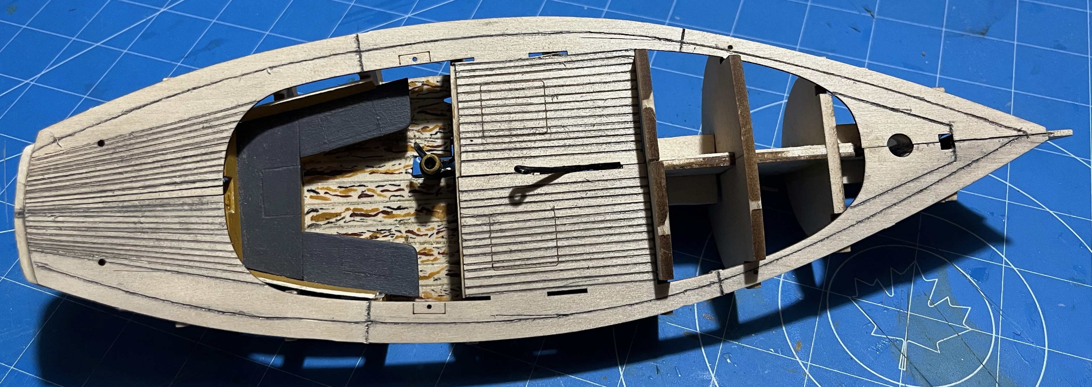
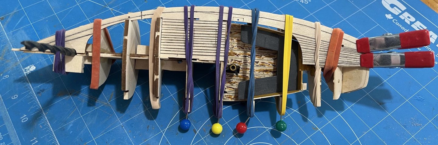
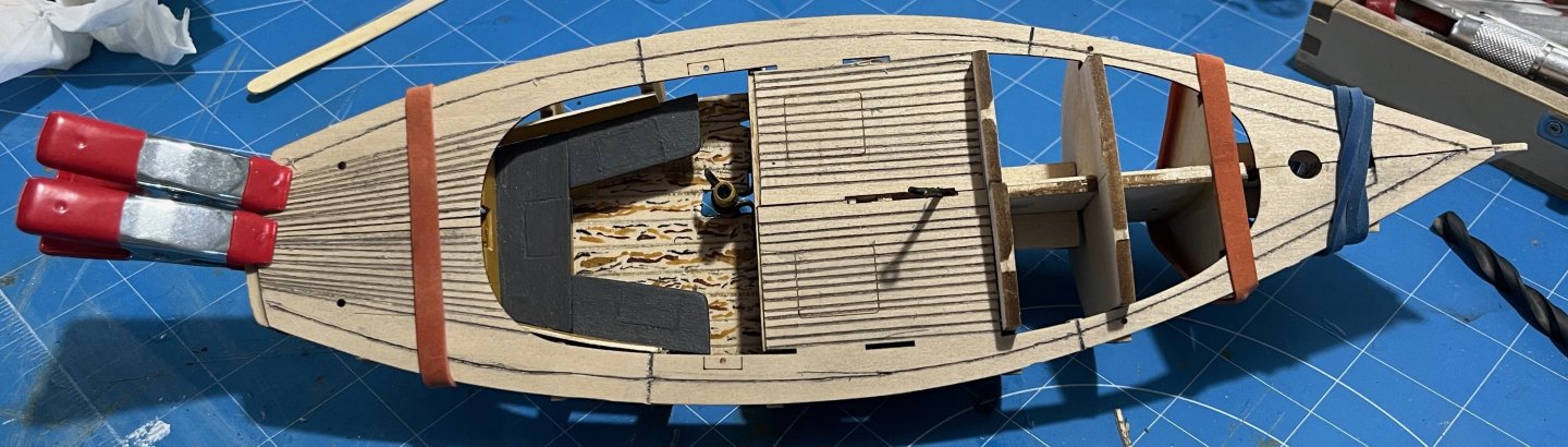
Today was decking the sloop. The instructions book for this kit definitely supposes that the apprentice builder has experience with the dory and/or pram. It offers not one word about preparing the model's skeleton to receive its deck, but the usual work is needed. There is char to be sanded off (including in slots in the bulkheads that will later receive cockpit coamings and cuddy sides), slight bevels to be worked in the tops of the bulkheads (to match the sheer), any necessary corrections to bulkheads set too high or too low (none in my case) and any other necessary fixes (for me: sanding Bulkhead 4 to give a smooth surface for the cuddy bulkhead to come, where a offset in the bulkhead halves left a step). I also scribed a seam that divides the waterway in two, preventing it from looking over-wide. Some build logs suggested sanding away enough of the central spine that the deck sits flush with the stemhead, facilitating later addition of the bowsprit. I preferred to maintain the curve of the sheer and will add a fillet over stemmed and gammon knee later, if necessary. With that lot done and a 1/4-inch drill bit inserted in the mast hole to help line everything up (as per the instructions), the first side of the deck went on easily. The instructions suggest starting amidships and working towards the ends but I preferred to start at the bow, where there was more critical alignment and work aft. The instructions also suggested wetting the surface of the deck piece to make it more flexible. I didn't need to, perhaps because of all the scoring of "seams". I just applied glue, held under finger pressure for 2 minutes, added rubber bands for reinforcement while the glue set up, then moved aft and repeated. My only problem was that the rubber bands did not want to stay securely over the ends of the bulkheads, so I had to pin them. That gave me: Once that had had time to set, the other side went on nearly as easily. Pulling the centrelines together aft of the cockpit did lift the side-deck off the bulkheads, so I got the after alignment glued down, then went back along the side. I found that I couldn't use many rubber bands as their pressure on the sides caused the scored piece between cockpit and cuddy to pucker. In the end, I relied on finger pressure and got: After all was set and the bands taken off, I have: Starting to look like a boat! There's a tiny amount of tidying up to doing forward of the cuddy and even smaller amount just forward of the centreboard slot. There's a bigger problem at the forward edge of the cockpit. Like others before me, I found that the planking there was just a bit too short. More exactly, it was too short to starboard, probably because I have the bulkhead very slightly off square. I trimmed the length on the port side before adding that to the model (reducing the risk of splitting something while cutting) and must now trim the starboard side to match. Then I will add a thwartships plank to make a deck-edge. The bigger problem is apparent right aft. Perhaps because of the repaired break in the centreline structure, the transom seems to be angled too far aft. That will be easily fixed by inserting a curved "plank" across the ends of the regular planking. However, the transom is also displaced to starboard of the centreline. (The deck centreline is exact to my pencilled mark of the skeleton's centreline.) I will have to trim the starboard side of the transom and see whether I can build out the port side a bit. Then the deck will need some cleaning up and a finish that will keep it clean while the rest of the work proceeds. I'm thinking of Miniwax Wipe-on-Poly (satin finish), which seems to get positive comments on other MSW threads, though I will test some on scrap basswood first. I'm also thinking that the outer half of the waterways should be the same white as the topsides, while all future gluing surfaces must remain bare wood for now, of course. Any thoughts or comments would be most welcome! Trevor

-
Moving right along ... I painted and fitted the two pieces bent yesterday. They will need a touch of filler and paint once the cockpit coamings are in but OK to proceed now. So I fitted the broken-off after portion of the framing, with a couple of cocktail sticks pinned on a temporary battens to support everything until the deck takes over that role: And that means that I finally ready to start making this mess look like a boat! Trevor


-
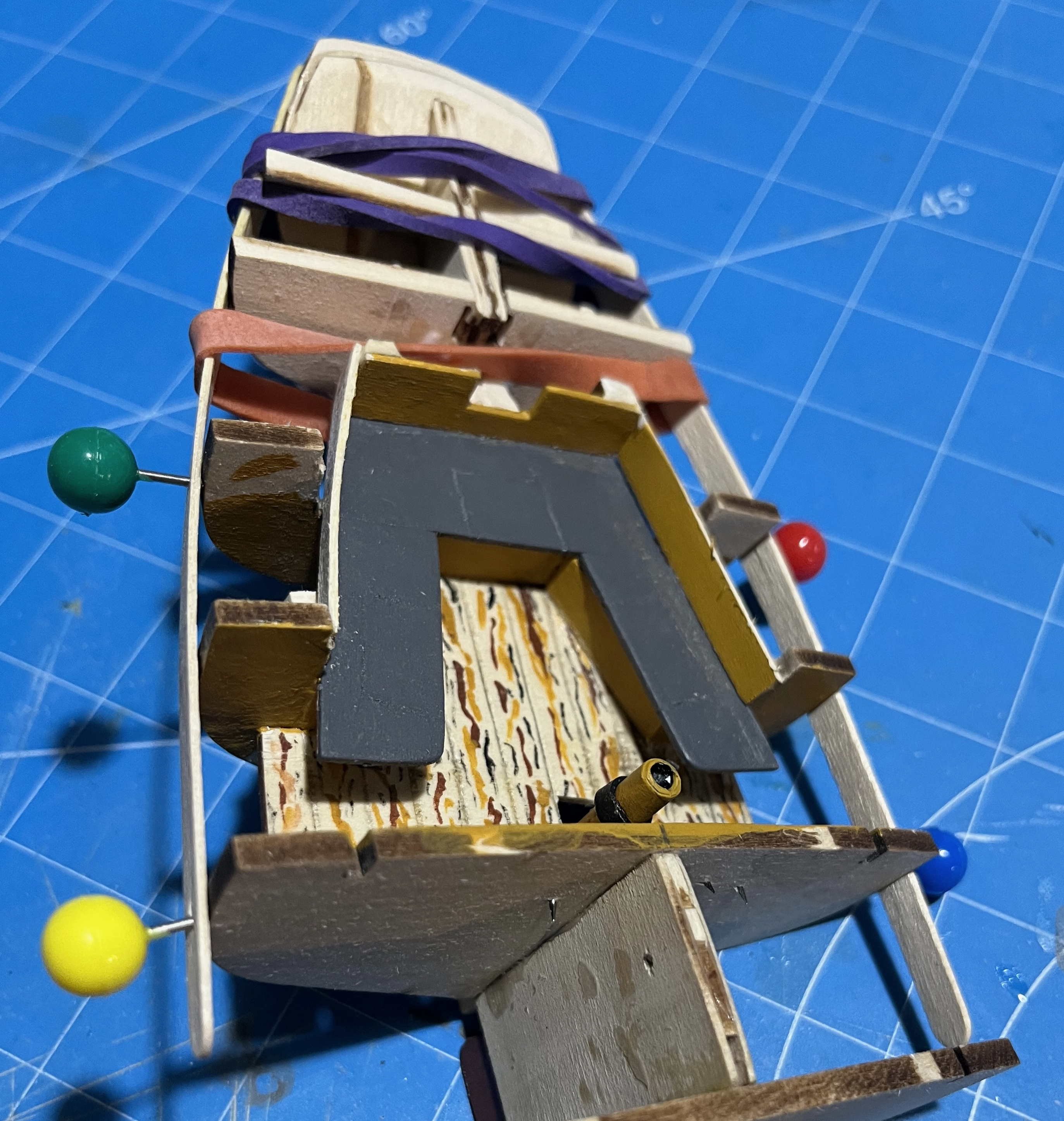
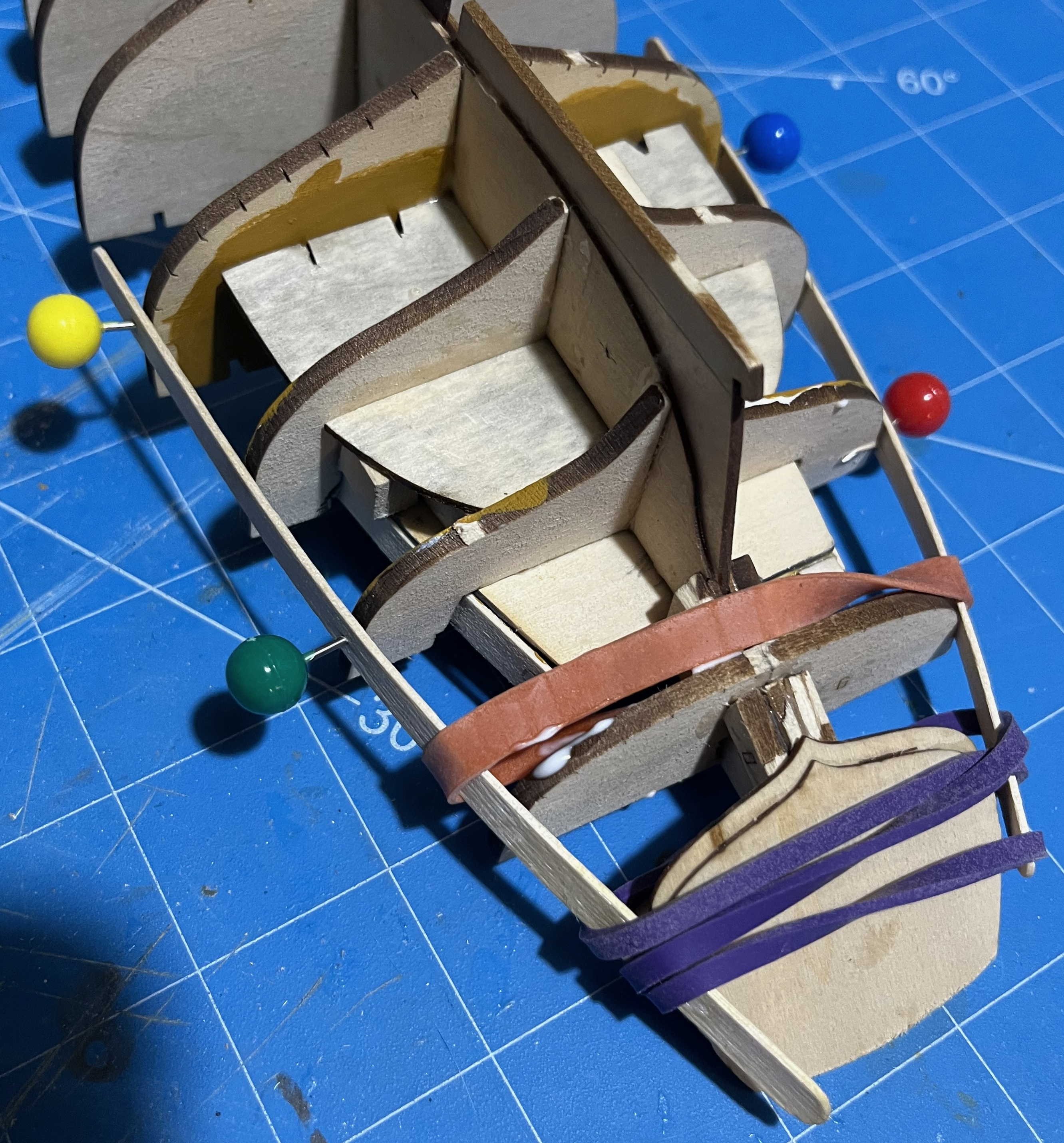
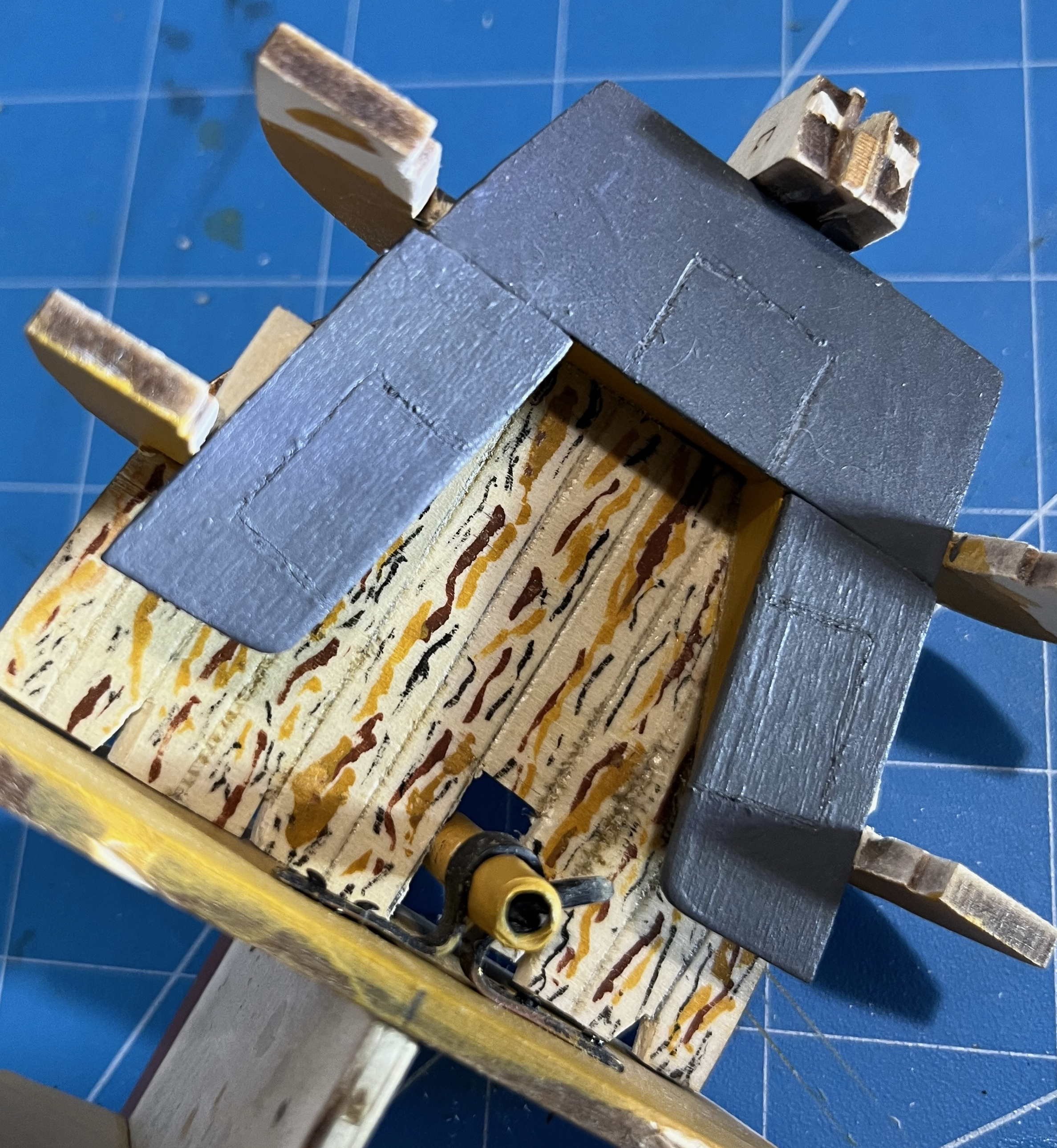
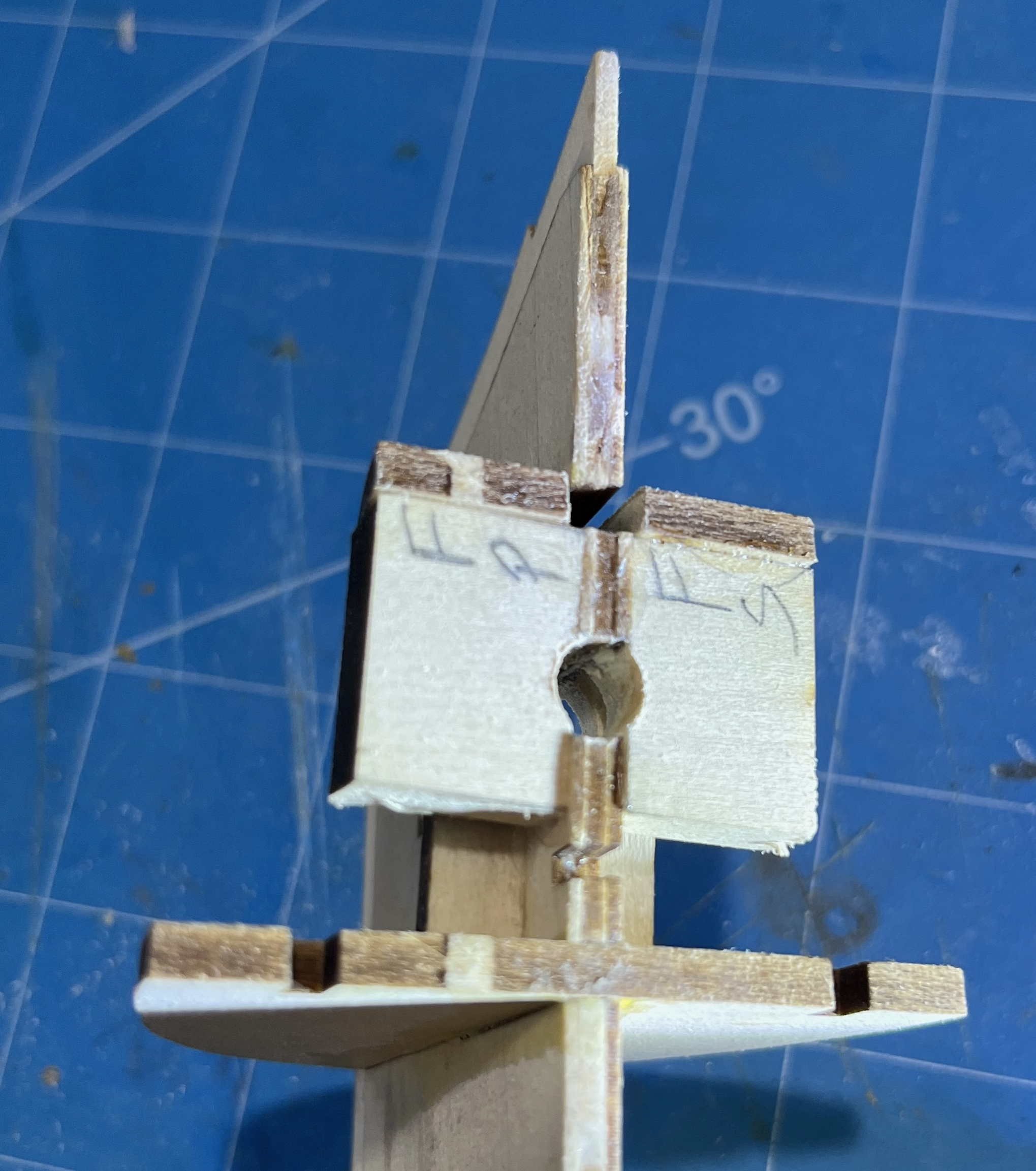
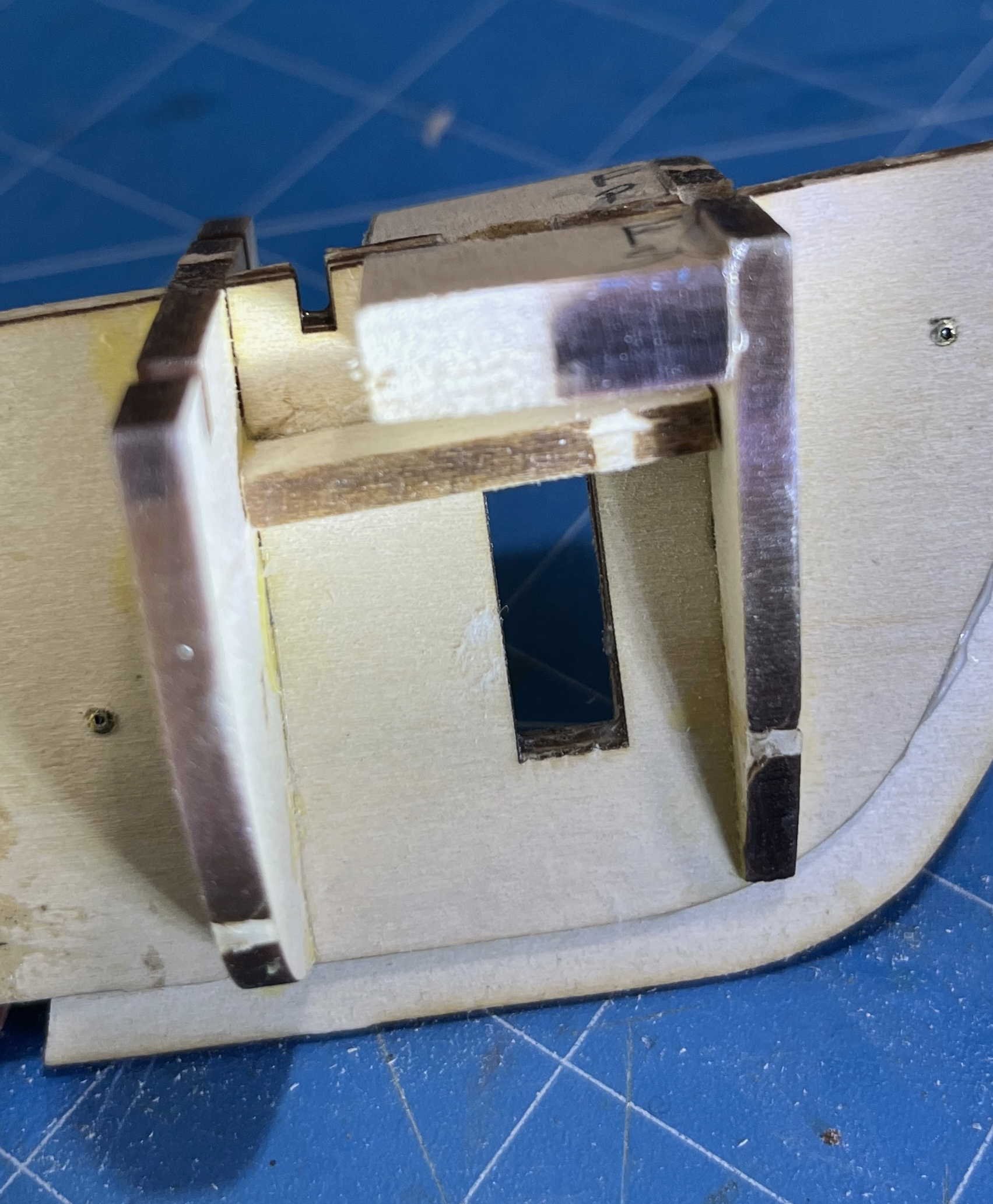
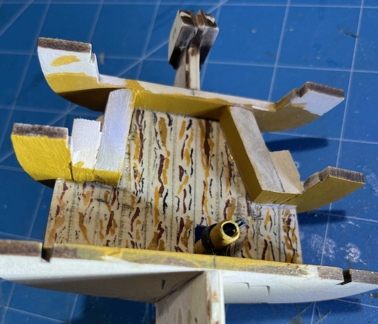
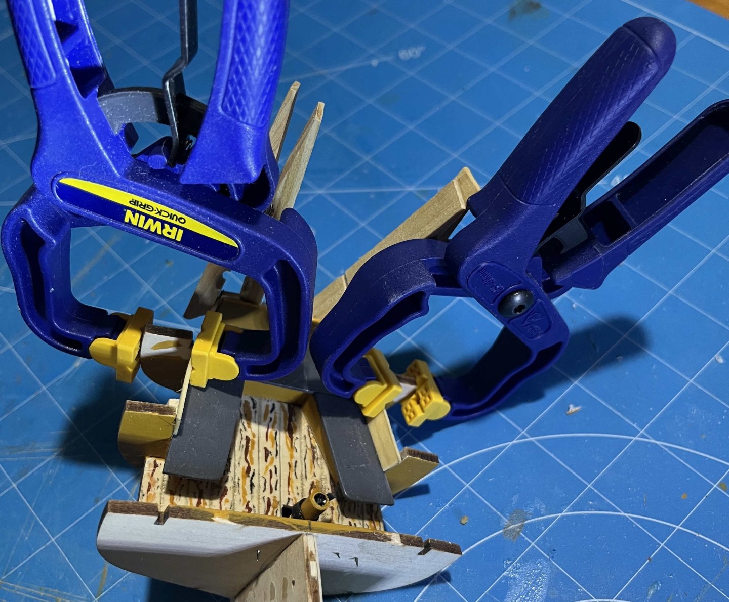
Finally got some serious time for model building again. (Editing a manuscript to suit the peculiar format of a particular academic journal can be a ***!%$$*** pain!) Not that I have been entirely idle, but my attempts at completing the sloop's cockpit went off the rails, so I had to back up, fail again, then realize that there was an easier way. The underlying trouble is something I mentioned in Post #8 of this thread: Plank-on-Bulkhead is a very practical approach when modelling a fully-planked hull, without the complications of the structurally realistic Plank-on-Frame alternative. However, P-on-B doesn't work with models of open boats, which necessarily display the internal structure to a viewer. Substituting a few bulky bulkheads for more-numerous but slimmer timbers can only leave an ugly misrepresentation. (Hence (presumably) the choice of dory and pram for the first two steps in the Shipwright series: Each has a simple internal structure that could be represented accurately without being overly demanding for those of us starting out.) But what of the Muscongus Bay boat? She is mostly planked over but the cockpit is open (in the sense that an open boat is open). The kit is designed for P-on-B construction anyway and yet the bulkheads show as big, chunky, unrealistic features -- as the photos in the instructions, and multiple build-logs, confirm. The proper answer, of course, would be to substitute Plank-on-Frame construction between Bulkhead 6 and the sternpost and between the deck and the cockpit floorboards. If the kit was designed to have the bottom and topsides planked before the deck is added, I might have gone that route, but the model actually needs the deck for strength before fairing and planking begins -- while the deck would seriously impede access to the area to be framed. Working around all that sounded far too demanding, so I scratched that idea. An alternative was suggested by another simplification in the kit: The very limited evidence we have of the Muscongus Bay centreboarders suggests that the cockpit seats were light and simple -- probably supported outboard by stringers on the top timbers, with a pillar to support the inboard, forward corner. Yet the kit has a solid block each side as a seat support. And that looks a whole lot like the front of a cockpit locker, with the space under the seat closed off. So why not extend the visual simplification and close off the whole space where the bulkheads are visible in models built straight out of the box? I doubt that any lobsterman of 1890 had the interior of his cockpit closed off like that but I am quite certain that he could have done, if he had so wished. So I'm fiddling with reality and going for that appearance. Besides, I aim to show a working lobsterboat at work, which means that she has to be carrying all of the gear that would be needed within reach: Coils of spare hawser for whatever may arise, likely most often anchoring in deeper water; more coils of lighter rope for repairs to rigging, along with some blocks and shackles; likely a set of spare pump valves; some replacement lobster buoys and buoylines, for ones in danger of parting off; a grapple to drag for traps whose buoys have been lost ... and all the other bits and pieces that boats accumulate, save items small enough to be stowed in the cuddy. If the kit's cockpit seats were shown like those in the few surviving photographs, I would have to model all that. But, by choosing to assume closed-in lockers, I can portray the sloop with all of her gear aboard and yet not create more than a small fraction of it! So that is what I am doing. My first problem was with the kit-supplied seat supports. Their after ends have to be bevelled to fay against Bulkhead #8, which is easy enough. But pressing them in tight while the glue grips makes the angled end slide. So it was out with the isopropynol and try again. Second attempt was just good enough, so I accepted that, then sanded the forward ends flush with Bulkhead #7 -- simplifying construction but also hiding a future mess under an overhanging seat end. I got into trouble trying to lay thin basswood across the forward face of the support and bulkhead. (The material kept breaking along the grain.) So I sawed, sanded and filed the blocks seen in the photo, filling the gap between support and bulkhead. I had painted as much as possible before gluing but, once all was set, there was sanding to get surfaces flush, then careful priming, followed by three coats of yellow ochre on exposed surfaces. The cockpit seats went on top without trouble. Grey paint is best for seats on a work boat, as it doesn't show dirt or (more important) scratches and gouges that cut down to bare wood -- wood that swiftly goes grey! Also: Closed-in lockers require openings in the seats to provide access. I marked those by scribing the surface to indicate lift-out sections. To improve things, I tried painting the grooves black, intending to scrape off the grey when all was done. However, the paint didn't want to come off, so I am left with just the scribing. The kit provides a piece to fill between the after edge of the seats and the deck. I needed two more pieces to cover the inboard faces of Bulkheads 7 and 8, from the seats up to the bottom edge of the coaming. It turned out that those would need to be twisted if they were to meet the ends of the kit-supplied crosspiece, which itself would need stiffening to support the side pieces. So it was time to soften two tiny pieces in boiling water, then clamp them in place to dry: That's as far as I have taken the cockpit for today but I did make one more advance: I aim to give the sloop the rig that Chapelle described, with no shrouds, but I don't fancy the consequences of my clumsy hands striking the top of the mast, if that is only supported laterally by the thin basswood of the kit's deck. So I added "mast partners" at the level of the underside of the deck, with a hole between sized for the mast: I have been making some progress on a display-stand too but more about that once it is finished. Next up: Get the cockpit side pieces into place, add the broken-off after framing, then it will be time for the deck! Trevor


-
Nate's PANDORA in 3D
Kenchington replied to 3DShipWright's topic in CAD and 3D Modelling/Drafting Plans with Software
I don't want to rain on anyone's parade, still less get drawn into an argument, but in a spirit of constructive debate: Maybe someone simplified the draughting and drew the timbers with straight tapers, rather than steps. The lesser siding of the top timbers is still represented in the draught. Yes there are. It is only that the draught was (again) simplified by the chocks that both joined at set-apart the two halves of the pair being shown only for one pair (the ones that frame the forward side of the fifth gunport counting from the bow) and omitted for the others. There I do agree with you and I am left wondering why. My best guess (and no more than that) is that the gunports compromised the strength of the hull so much that the frame had to be adjusted to minimize the weakness, whereas lesser holes could be worked in as an where needed while the ship was being built. I don't understand what you meant by that. So the shipwrights were required to trim the scantlings of the available timber, trimming more in some parts than others? That's no criticism at all. I see no reason to doubt their accuracy. Nor that they were "complete" for the purpose for which they were prepared, though most certainly incomplete as exact representations of the frame of the completed ship. There I must disagree. The author of Shipbuilder's Repository (who did not even put his own name to his book, let alone produce some sort of official textbook) gave recommendations, not rigid rules -- which did not exist. For the details of a particular ship, we must turn to draughts of that ship, the nearest for which details are available or else seek the underlying principles from study of many draughts. Trevor -
Nate's PANDORA in 3D
Kenchington replied to 3DShipWright's topic in CAD and 3D Modelling/Drafting Plans with Software
I (almost) agree with your 77%. (The top-timber siding tabulated in the Repository rounds to 100% of the 4th futtock, not 99%.) But I can't agree that the framing diagram you have presented omits that detail. Setting dividers against the diagram on my monitor shows the siding of the head of a top-timber amidships is close to three-quarters that of the floor -- call it 77% or 78%. More generally, while no one source can be trusted as absolute truth and we need to understand the intent behind each type of diagram, I would suggest that (in general) drawings made by the people who designed and built the ships (e.g. those now in the Greenwich collection) are more trustworthy than modern interpretations -- especially interpretations by enthusiasts whose skills lie in draughtsmanship, rather than ship design or nautical archaeology. Trevor -
I stand corrected. But that makes the evolution shown in the painting distinctly odd -- at least to my eye. The topsail sheets remain taut, with the clews hauled out to the yardarms of the lower yards, as expected. The topsail clew lines have likely been hauled, to aid gravity in bringing the topsail yards down to the lower-mast caps. Again, nothing odd in that. What fooled me is that the lower third of each topsail leech remains semi-taut (not billowing, as the upper 2/3 are), while the bunt of each topsail is stretched to the yardarms of the topsail yard. (That's where I went wrong: It looks like the heads of lower topsails are bent to yards, when it is the bunts of deep topsails stretched.) So what have they done? Taken up tight on the reef tackles of deep reefs on each topsail? I guess that might be an effective way of temporarily reducing the power of the rig, while still keeping some headway, but I don't recall hearing of that before. (Maybe I should re-check Harland's book!) Or should we just question the artist's understanding of sail handling? Trevor
-
Even if a spherical ball could leave the muzzle at supersonic speed (very improbable with black powder as propellant), it would very quickly decelerate. The aerodynamics of a sphere are poor indeed! Trevor