

Seventynet
-
Posts
730 -
Joined
-
Last visited
Reputation Activity
-

 Seventynet reacted to tlevine in NRG Rigging Project by tlevine
The cheeks are located on either side of the mast. Their inner surface is flat so the sides of the mast will need to be flattened. On this ship they are 25 feet long and extend from the bottom of the mast head to approximately 12 feet above the deck. At this scale, that is 6.25” long, ending 3” above the deck. A template is included in the practicum. The upper part of the cheek is called the hounds and is thicker than the rest of the cheek. The photo shows the cheek before and after shaping.
The outline of the cheek was drawn onto both sides of the mast. This outline marks where the mast needs to be flattened. The hounds remain flat but the rest of the cheeks were rounded over. The apparent concavity in these cheeks below the hounds is an optical illusion.
0
The cheeks were then glued to the mast. Look at the straight line extending up the mast on the side view and the step-off above the hounds fore and aft.
The next step was to make and install the bibs. These are forward extensions of the hounds and their purpose is to support the trestle trees. They are the same thickness as the hounds and are attached with a morticed scarf joint for strength. This is how I made the mortice. Start by drawing the zig-zag mortice onto the hound. It extends approximately three-quarters of the length of the hounds. Because the lower end of the bib is curved, the bottom mortice cut is also curved.
Since I was using basswood, I used a #11 blade to inscribe the mortice. I did this a few times, deepening the cut with each pass. Once I was halfway through the hound, I used a chisel to remove the wood from the mortice. I have used pencil to make the joint more visible for you. This joint would not have been caulked and so the joint would not be very visible. It is important to keep the sides symmetric.
Next, I drew the bibs on paper. The top of the bibs is 3/8” wide and it is half the thickness of the cheek. I laid the paper over the hounds and made a pencil rubbing of the mortice to get the shape of the tenon. Each side will be slightly different so two templates were needed. The one below is marked “S” for the starboard side.
The front edge of the bibs was rounded over and installed; the top edge was left flat. There is a forward angulation to the bibs to allow the trestle trees to rest on them parallel to the water line. The top edge of the hounds and bibs should form a straight line.
-
Seventynet reacted to tlevine in NRG Rigging Project by tlevine
The lower mast and trestle trees must be made before installing the lower deadeyes. There are many ways to make masts and yards, including using a round dowel approximately the right diameter, turning a wood blank on a lathe or chucking a dowel into a drill and sanding it down to the correct dimensions. A fourth technique will be shown here. The only tools required are a caliper, a sharp chisel or plane and sandpaper.
A jig is needed to hold the wood during the shaping process. The picture below shows two types of jigs. The top two homemade jigs only differ in the diameter and length of wood they can hold. The lower jig was made by Hobbymill, which is no longer in business. It is a single jig with multiple sized slots. I prefer the security of the single size jig. With either type of jig, the final diameter of the mast or yard must be greater than the height of the V-slot on the jig. The practicum will give instructions for making the jig.
Before going any further, a few terms need to be defined. The part of the mast above the trestle trees is called the mast head. Below the trestle trees, the mast is divided into “quarters”, starting at the mast step in the hold. “Cheeks” (not illustrated) run on either side of the mast below the mast head and provide additional strength to the mast. The “hounds” are the upper parts of the cheeks. Later era ships have a “fish”, similar to the cheek but located on the fore side of the mast. The relative length and shape of these pieces vary by size and type of ship, country and era.
-
Seventynet reacted to tlevine in NRG Rigging Project by tlevine
The bit pins are 9” square posts. The crosspiece is 8’ x 10” x 3” and connects the two pins. It is morticed into the pins 3’ above the deck. Shape the ends of the crosspiece as seen in the picture. I raided my scrap box again for these pieces but the kit will contain the correct thickness of basswood to construct them.
I used the previously drilled pilot holes to locate the centers of the bitt pins and lightly traced the outline of the bitt pin onto the deck. A series of holes was drilled inside the outline and they were connected with a #11 blade. They were enlarged with files until the openings were just large enough to allow the bit pin to pass through them. They will not be permanently installed until later to make installing the mast easier.
This is how the model looks with everything temporarily installed.
Other than installing the channels, the hull is complete. Next, the wale was painted. The hull planking was masked off above and below the wale. I used three coats of artist’s acrylic paint diluted 1:3 paint to water, sanding with 400 grit sandpaper between coats. I remove the tape as soon as the last coat has been applied to prevent paint adhering to the tape.
-
Seventynet reacted to tlevine in NRG Rigging Project by tlevine
As I mentioned before, the bit pins will be glued to the “B” spacers. I measured and marked two feet (½” scale) aft from the aft surface of Frame 4 and nine inches (3/16” scale) inboard from the spacers. These are the centers of the bit pins. Small pilot holes were drilled up through the deck.
I planked the inner bulwarks, starting at the waterway, using ten-inch-wide planks. I applied a clear finish at this point. The top of the bulwarks was sanded flat in preparation for installing the cap rail. Simply turn the model upside down and sand the bulwark the way you did the base. This also gives a fresh surface to glue the top rail onto.
Templates were made to determine the shape of the rail. This is how I made these. Masking tape was run along the upper edge of the hull planking to prevent marking the wood. The model was turned upside down and, hugging the side of the ship, a line was drawn along the top of the hull. Don’t forget to mark fore and aft, port and starboard.
The rail is 12” wide with a 1” overhang inboard and outboard. I drew lines 1” (0.02”) outboard and 11” (0.23”) inboard of the original line. The picture shows the templated line and the overhangs.
I cut out the templates with a lot of extra paper on either side of them because long, narrow pieces of paper are prone to warping. They were glued to the 1/32” wood sheet. I use either Elmer’s glue stick or glue spray that is not water based (3M-45) to help prevent warping. Both of these adhesives can be removed with isopropanol and scraping. This is another opportunity to check out your scrap pile for a piece of contrasting color wood.
Cut out the rails and mark the undersurface with the side and orientation before removing the template. Remove the template and round over the edges. If you want a contrasting color for the rails, paint or stain them before installing.
-
 Seventynet reacted to giampieroricci in HMS PEGASUS by giampieroricci - Scale 1:36 - Swan-Class Sloop from plans by David Antscherl & Greg Herbert
The bow structure is finally finished. Some details are missing, which I will do later
-
-
Seventynet reacted to sfotinos in Sloop Speedwell 1752 by sfotinos - Syren Ship Model Company - 1:32 Scale - POF Sloop
Just a quick little update.
Needs some clean up and on to tapering.
-
Seventynet reacted to Chuck in Sloop Speedwell 1752 by Chuck - Ketch Rigged Sloop - POF - prototype build
Lots of drafting to do....Deck Layouts almost completed.
-
Seventynet reacted to jpalmer1970 in The Hayling Hoy by jpalmer1970 - 1:48 scale - First POF build
As it is a holiday weekend I was able to spend a little more time on the model. I did cut out the boxing joint on the forward section of the keel with my small chisels but I wasn't happy with the result as I shaved a little too much off the 'tooth' (it probably has a proper name but I'm not sure what it is!) at the end. The temptation just to tidy things up a little is very strong - until you go too far! Consequently I remade that part of the keel again and redid the joint, this time taking much more care with the chisels and only working on specific sections of the joint at a time. The second iteration of the joint was much better that the first attempt and so I'll see how I go when I cut out the lower part of the stem joint before deciding whether this is a keeper. I used my mini mill as a spindle sander to help shape the curved sweep of the top of the piece.
Here is the second version of the forward section of the keel with the boxing joint.
I also cut out the lower and upper stem pieces and the outer keel post from the 12" stock. I experimented with tracing out the shapes on the wood and also gluing templates on the stock before cutting them out on the scroll saw. I'm not sure which is the most accurate way to use going forward but the cut out templates certainly seem to be easier to see, for me at least. I'm also finding difficult to judge how much excess to leave on the piece with the scroll saw - I realise you need to be close enough so you don't have to do too much sanding to shape but at the same time you need to have enough excess to make sure you are not going to end up with an undersized piece. No doubt I will get better at this when I start cutting out the dozens of pieces that make up the frames!
I also used some 6mm acrylic to make the support mounts for the stem and the stern. They may not be the prettiest supports ever but they are square and after lining the cutout with sticky backed felt a 12" timber fits in there nice and securely.
I think the next job will be to trim the keel sections to length and cut the scarph joint for the forward section of the keel.
-
Seventynet reacted to Bob Cleek in Proxxon mini lathe verdict
I don't doubt the satisfied testimonials from those who have the mentioned Proxxon woodturning lathe, but to my way of thinking, it's a lot of money to spend on a machine that doesn't do the job any better than a shop-made jig and an electric hand drill. (Hold your drill in a vise or clamp it to the bench somehow and rig a "pillow block" with a hole in it at the other end clamped to the bench to steady the other end of the stock and prevent whipping.)
An accurate taper on any mast or spar is, in my experience, at least, easily achieved by using a plane to "knock the corners off" down to the proper taper and then finish-sanding it round past eight or sixteen sides, depending upon the size of the spar diameter. If one wants to make sure the taper is fair and not "wavy," as one should, the solution is to sand the spar with a long, flat batten with sand paper attached to it. If the batten is kept flat against the stock as it turning, the taper that is developed will be as fair as the face of the flat batten. You will have to do that to turn a spar on these lathes that have been mentioned. There's no way you will be able to turn a fair taper over the length of a spar using a turning tool on a short tool rest.
Unless one has a lot more need for a milling machine than to work hexagonal flats on wooden sticks, it's a very expensive way to get that job done. You don't need a mill and if you have the money to buy a mill, you'd get a lot more use out of a Byrnes table saw for less money. It only takes eight passes on the table saw using the taper jig and a "vee-trough sled" to hold the squared stock on edge to take the last four cuts to form the tapered octagon and you'd be done in no time with accuracy to .001 one the Byrnes saw. Don't forget that, although woodturning lathes have less need for tooling, you can expect to put at least as much money into tooling for a metal working lathe or milling machine as you did into the bare bones machine itself, and that's just to do the basic evolutions possible on the lathe or mill.
Your concern is well-thought out. A woodturning lathe simply spins a stick or block of wood so you can run a cutting tool against it to make shapes. Neither this Proxxon lathe nor the Chinese offerings pictured will do anything more. They will not cut threads. They cannot be upgraded to cut metal. You can turn wood on a metal cutting ("engine") lathe, but not the other way around. You will spend every bit of $500, and likely closer these days to $800 to purchase a Chinese Sieg "7X" (the longer the better... I think they go up to 7"x14") and the same amount again to get the tooling you'd need to have it do all it can. (You get what you pay for on these. Don't think you're getting a bargain if you see "the same lathe" for a lower price at Harbor Freight or a "flashier" one from MicroMark. They are built to the retailer's specifications and if you buy a cheap one, you are going to have to fettle it yourself to get results anywhere near the accuracy you ought to want. Only buy one from the Little Machine Shop or Grizzly. They stand by theirs.) Sherline and Taig also offer quality machines that will do similar work, albeit on a lighter machine and with less of a selection of after-market (and considerably less expensive) tooling. Those three are your options, the Sieg's being the least costly. You can cut threads on each of them and you can turn wood and metal on all of them. They are far more versatile than a woodturning lathe. If one purchases the Proxxon woodturning lathe or an equivalent, they will have to additionally purchase a separate metal working lathe if and when they want to turn metal or plastics. If they want one, fine. There's nothing wrong with the Proxxon lathe except that it's a lot of money for what little it does and in my opinion that same money would be better spent invested in a more versatile tool.
Unless you want to specifically buy a lathe, in which case I'd definitely say money spent on a metal working lathe is money far better spent than money spent on a woodturning lathe, it seems like all you really need in addition to the drill motor or drill press you already have is a flat stick with some sandpaper glued onto it and perhaps a nice little hand plane.
-
Seventynet reacted to jpalmer1970 in The Hayling Hoy by jpalmer1970 - 1:48 scale - First POF build
Hello,
Welcome to my build log of the Hayling Hoy. David Antscherl's excellent book on this build says that it is suitable for a first time builder attempting a fully framed model. Well, I am certainly a first time scratch builder and this will be my first fully framed model so I hope he is correct! I decided to attempt this build as I wanted to stretch my skills and techniques and also because I knew it would be a very long project. I really don't have that much spare space to display finished models and so the longer I can keep one on the building board the better! I was impressed and encouraged by previous first time scratch builders who have also attempted this build, notably @Stuntflyer and @Seventynet and I hope I can come up with something that even approaches their excellent work.
I have no background or experience in woodworking and whilst I do own a few of the machines that may help with this build, eg table saw, thicknesser, mill etc I haven't had a great deal of experience using them to date and so this will be a learning experience for me on those tools as well as in regard to the techniques of scratch building a fully framed model. There will be plenty of mistakes and do overs on the way but I'm not worried about that as it will all be a part of the project. I will of course welcome any advice and ideas from people who feel that they would like to contribute. I know I have a lot to learn and I am looking forward to it. Progress is going to be slow as I don't get that much time each week to devote to modelling but hopefully I will keep going forwards!
Being based in Australia I really don't have access to the lovely types of wood I often read about on this forum but there are of course native options. I have decided to use some myrtle that seems to be in readily available supply. So far I have only purchased a couple of small pieces just to get started with. The myrtle seems very like pear wood (to my untutored eye at least) and hopefully will make a lovely coloured model with fine graining.
I have spent that last few weeks getting ready to start this project and that included getting the plans copied and making my building board. I used some mdf for the base of the board and added some pine battens underneath. I have seen a couple of builds that use t track as part of the building board and so I decided to copy that idea and I also made some wooden squares to use with the t track. I added a couple of coats of white paint to the board and then glued down the plan using some spray adhesive. It seemed like a good idea to add a coat of artists' varnish over the plan but clearly that was a mistake as it only succeeded in introducing lots of wrinkles - so that wasn't a good start. Either I hadn't glued the plan down sufficiently or the spray varnish just didn't like that particular paper. So off with that plan and on with another copy, this time glued down with lots of Bostick blu stick - and it seems to be sticking well so far. I didn't bother with the varnish this time around. I also extended the lines of the frames out onto the board which should hopefully make things easier to line up and keep square etc down the track.
Today I actually made a start on the build itself and began with cutting out the pieces for the keel. The keel is made of three separate pieces joined with scarps joints. The rear two pieces are simply 12" square lengths and I deliberately made them over long as I wanted to make sure I had plenty of excess to work with in case I made a mess when cutting the scarph joint. The scarph joints were cut on the table saw and then the faces of the cuts tidied up with a small chisel.
Strangely, the keel sections look far from square in that photo above but it must just be the perspective - they are square honestly!
Next job is to tackle the forward section of the keel with the boxing joint.
-
Seventynet reacted to Chuck in Sloop Speedwell 1752 by Chuck - Ketch Rigged Sloop - POF - prototype build
Work continues on the forecastle area. With those first two beams in position I can now start working on the bulkhead that sits against them.
In this first picture, I am just test fitting the three sections of laser cut bulkhead. These (like all others) are laser cut slightly wider and taller than needed.
First...work on getting a nice fit on the center section between the riding bits. Only worry about the width on both sides...dont worry about the height of these yet. The two pieces on either side are next...sand the outboard side ONLY to reduce the width and get a tight fit against the riding bitts. There will be a space between the frames and the bulkhead where the inboard planking would have been. Try and make it a consistent width. Again dont worry about the height.
Only after you get the widths taken care of should you then sand the top of each bulkhead section down so the height is flush with the top of the lower beam. The photo shows the three sections with a proper fit all around...now its time to detail them.
Remove the three sections so you can add the uprights and simulated deck beam. First up...sand the char from the laser cut beam pieces. These are glued to the top edge of each bulkhead flush. They are laser cut longer than needed so you can sand the sides flush as well.
Then the uprights go in position. These are the uprights for the cabins on the lower platform. We will be adding them a little later. But it is easier to add these now. They are just 1/8" x 1/8" strips cut to length and glued in place. There are laser etched lines that show you exactly where they should go.
Then glue the three sections in position permanently on the model. Note the riding bitts will not be glued on permanently yet. They will just get in the way when we are doing so many other things in this chapter. So make sure you can remove it after the three sections are glued in place.
Riding bitts removed.
Now for the next layer above that. this is handled in the exact same way. I could have just included these on the first three section only a bit taller, but I wanted to be able to paint them cleanly and get a crisp edge. But the same principle applies here. Sand the widths of each first....then get the heights done. These are flush with the top of the fcastle deck beam. Then remove them.....
Paint them red. Then add the laser cut and etched molding along the top edge. The molding was rounded off on top and bottom. You could also scrape your own if you want to.
Then sit this on top of the lower sections of bulkhead as shown below. The riding bitts are still removable but you must use them to get a good fit. Glue these bulkhead sections in position now as well.
Top this off with the margin plank along the beam. Cut a 1/4" x 3/64" strip for this. Basically, just like you added for the quarter deck margin plank. It hangs over the bulkhead a little bit. The aft edge hanging over is rounded off a bit to your liking. The forward side will leave a nice ledge or rabbet for the fcastle deck planking.
The only difference here is that you must notch out this plank for the riding bitts.
see below. Also the riding bitts are not yet glued in position...I will let you know when its best to glue that in position. BUT I did finally glue the fire hearth in place permanently. Just remember to do so without its stack. That will just break off later without a doubt. And if you want to add anything else to the galley...do it now. We are about to close her up for good with deck beams and knees, etc.
The three fcastle deck beams were cut to length and are just resting on the deck clamps. I must locate their exact positions using the plans.
Thats it for now...BUT I did get a chance to cut the plan sheet up to see how my planking design will look. Its always tricky deciding how much planking to add or leave off the model. I think I am liking this particular cut-away with some planking removed. You can still see quite a bit of stuff down there...
The hearth stack was just placed on top for giggles and a test.
I also did the same for the quarter deck...once again plenty of detail is still viewable down there. I will live with these templates for a while and mull over some other possible planking schemes. But so far I think these will do just nicely. What do you think?
-
Seventynet reacted to Chuck in Syren Ship Model Company News, Updates and Info.....(part 2)
I am not sure if I will add those details yet. I am still mulling it over. The reason why we builders add those fun details is to set our models apart from the many that will end up being made. It also means I have to build another set of every table and chair again so I can write the instructions for them...LOL.
But the Speedwell project moves forward at any rate.
Now working on fcastle details.
-
Seventynet reacted to niwotwill in HM Cutter Cheerful 1806 by niwotwill - Syren Ship Model Company - scale 1:48
Short post bringing everything I completed up to date.
Finished all the deck furniture
Lined off the hull
First plank laid
More planks tomorrow
-
-
Seventynet reacted to thibaultron in Laptop recommendations?
As far as CAD goes, you do not need a high core count CPU! All, I repeat all, CAD programs are single thread programs! I fell into that mistake when I built my new computer, last year. I have a 12 core CPU and none of my CAD programs were using more than 4 cores! When I investigated, all the 2D and 3D CAD program vendors state, if you look hard enough, that any CAD program has to be single threaded, as, basically, you start from one line,than follow it to the next line etc. CPU speed, on the other hand does matter, as well as how the CPU handles code.
I went from a decade old 4 core setup, with a clock speed of about 4GHz, to the latest 12 core AMD 7900X with about 5GHz. In single thread the old one got a score of 450, the 7900X 2400. So it is about 4 times faster. The "Scores" are relative to that particular Benckmark program, the ratios do, however, indicate the relative performance. In multi core tests the old one got about 2K and the 7900X 27K. I have detuned my 7900X to run at a slightly lower total wattage, to lower CPU temperatures, and it runs about 3 to 5% slower, but now stays in the low to high 70C range of temperature, under full load, rather than the 90 to 95C limits the manufacture allows it to run at, for maximum performance. Intel runs in similar temperature ranges. I could have saved some money and gotten the 7600 or 7700 CPUs, as the CPU intensive work I do is mostly CAD and, not video or picture editing. I don't know if Blender falls under the single thread limit.
Both the old and new computers use a maximum use 4 cores with my 3D CAD and Sketchup programs. Yes the program is single thread, but I guess some of the tasks can run in parallel.
For Graphics and most other processor intensive programs the more cores the better. Also more cores allow you to have multiple CAD programs running without one bogging down the others. For Instance to copy an item from one Sketchup file to another, you need to have two or more Sketchup programs running, with each having one of the items. You copy an item in the first program, then switch to the other program, and paste the that item into the second. You can also have two SU programs running, and have one doing something complex, that will take a long time, and work on a second project, in another SU program while you wait for the other to finish, without slowing everything to a crawl. The CPU intensive operations in my SU work are generally grouping and ungrouping the lines in an object, and importing some non SketchUp file formats. I have an older free version (2017) of SketchUp, so I don't have the other programs that come with the full version.
With my old computer, some of the operations might take overnight, on the new computer, a couple hours. Most now finish in a few minutes.
With the larger number of cores you can also open other tasks, say a different CAD or Graphics program, and work on those while the SU program calculates.
Graphics programs can use multiple cores, so the speed gains are greater.
I don't do gaming or video editing, so don't need as high an end a GPU either. I bought the AMD 7600 GPU, and it barely sweats with my workload.
If you get a laptop with a replaceable Nvme SSD, you will also see greater speed gains than one with a regular hard drive style SSD drive. That also allows you to replace a failing drive, or expand your capacity.
I would highly advise against a MAC! The SSD sticks in them are soldered in, and of a proprietary form factor. Also the most common MAC laptop failure is for the chip that converts the power supply voltage to the different ones needed internally to die. When it does a vast majority of the time, it sends 13 volts to the SSD, frying it, causing the irreversible loss of all your data! No I'm not making it up, I did a lot of research. Apple is increasingly making it impossible for outside vendors to repair them. The latest trick was to start using a "Smart" switch to detect if the laptop is open. If it fails you can buy a new switch to replace it, but not the program needed to program the smart part of the switch! Only an Apple owned repair facility has access to the program. Without that program the computer will not recognize the replacement part.
Whichever computer you buy, buy an external drive and frequently back up your files! Even if you have multiple internal drives, and back up the data to another internal drive, a major computer failure, say the power supply, can destroy all the internal drives!
Also the minimum RAM I would recommend in a Windows PC is 16GB, with 32 or 64 if you are doing anything other than browsing or word spreadsheet work. As before, if picture or video editing the more memory the better. I understand that professional video editors regularly run 128GB of RAM. As an example, here is a screen shot of the set of Bogard cannons I am CADing in Sketchup, with this program and the browser I'm writing this response on, I'm using 11GB of memory. Opening a slightly older version of the same file, it goes to 14.6GB. So 32GB would be the minimum I need. I have 64GB, but the additional 32GB of memory came with the bundle deal I got when the CPU, motherboard, and memory bundle I got when buying the components from MicroCenter.
In the graphic above the cannons farther from the center line are the latest version of that particular size. I build them in stages (make the body, add cypher, add trunnions, etc.), saving each stage as I go.
-
Seventynet reacted to Mirabell61 in ELBE 1 1948 by Mirabell61 - scale 1:87 - Lightship
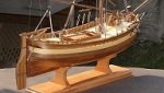
Update.
Today I took her (cut) off the build platform, and had my first look into the hull, am pleased with it so far.
Outside against the bow-post and the side skin I installed the integrated round pod that later on takes up the mushroom typ anchor, (3 tons in real weight).
Its the first time she settles on her own standplate
Nils
the pod for the mushroom anchor later on. It faces downwards to a certain angle and ends a bit above the waterline
its made from 20mm round beechwood. The face is light convex, as it fits neatly into the concave shape anchor
the overstanding upper frames will be cut off
a sight into the hull
here to be seen one of the spindle counter nuts, and the resting foot lug for the light towers stand tube. This is also why I built in the squarebar on the topside of the keel
the shining through narrow plank gaps are filled with white cured wood glue. the hull at this degree of building is extreme light
-
Seventynet reacted to Chuck in Sloop Speedwell 1752 by Chuck - Ketch Rigged Sloop - POF - prototype build
Not back in that cabin….take a look at the original draft. The captains stateroom is on the lower platform….an even smaller space. These were small vessels and working mainly coastal.
Smaller crew and even smaller spaces. Heres a look at the original draft and cabin spaces.
-
Seventynet reacted to woodartist in Does cherry carve well?
Cherry carves very well, holds detail. is hard to crush, and is not prone to splitting. Below are two carvings I did in cherry.
-
Seventynet reacted to Erik W in HM Cutter Cheerful 1806 by Erik W - 1:48 scale
One last photo for the week. I drilled the interior scupper holes. This was a bit nerve wracking. I hadn't anticipated how easy it would be for the 1/32" x 1/32" waterway strip to split while being drilled. I wound up starting with a much smaller drill bit and then using three more progressively larger sizes to only take a slight bit of material off at a time. I made sure to turn the pin vice really slowly. If the waterway split, the split part was still attached at one end. I took a sharpened toothpick, applied a tiny amount of wood glue, and glued the fragmented sliver back down. I had to do that with three of the holes. The splits are invisible. Glad I'm done with that part!
Also, I'm not sure of the properties of wood in general, but I'm curious if my boxwood, which I've had for 9 years in an inside climate that has a humidity of around 25% most of the year, splits easier because of that.
Erik
-
Seventynet reacted to Erik W in HM Cutter Cheerful 1806 by Erik W - 1:48 scale
This week I decided to mix things up a bit, taking a break between making the backstay plates and the chain plates. I made the 22 eye bolts for the hull exterior and cap rail top. While I have every manner of small diameter wire - lead, brass, copper, phosphor bronze, steel - down to .002" diameter, I didn't have the type of wire best used by ship modelers for these types of things. So after some research on this forum I ordered both 24 and 22 gauge Hillman Group dark annealed wire. I must say, trying to make 22 identical eye bolts was more of a challenge than I thought it would be! I never did get to a point where they were consistent. That said, I selected groups that were close to identical to one another to fasten in the same area. I figure if the port side eye bolts are slightly different than the starboard, a viewer would never know since you only see one side of the ship at a time. I followed what Mike (Stuntflyer) had done in his Cheerful build log, and filed a little channel around the holes so the eye bolts snug down a bit.
I also drilled the scupper holes in the outside of the hull. This was pretty straight forward, other than when I went to photograph the model I could see the bright wood on the inside of the bulwark. I wound up taking a fine brush and painting the interior black, followed by running a pencil around the plank edge of the hole.
My next step will be to drill the scupper holes on the interior bulwark/deck area. Does anyone have any advice or wisdom on that? Am I drilling all the way through the interior planking? I know I need to make the holes so they notch into the lip of the waterway at deck level.
Erik
-
Seventynet reacted to Chuck in Sloop Speedwell 1752 by Chuck - Ketch Rigged Sloop - POF - prototype build
One of the benefits of working at 1/32" scale is of course the size. I think its easier to handle the parts and keep things neat and tidy. But in addition to that you can really get a lot of details in there. Stuff I would never attempt to add on smaller scales. Further, 1/32 and better yet 1/35 scale is a very popular modeling scale. There are so many aftermarket parts and details available for builders at this scale. This includes figures and accessories. Like the small cups and pitcher. Its all readily available on Etsy or Ebay. Its also fun to just look. I am waiting on a few other things I made add.
The barrels are Syren barrels. I am also getting some new ones in stock I think you guys will like. It might be a while though.
The checker is still very tiny but that is laser cut by me including small very teensy checkers. The stools are also laser cut in cedar and very differnt from the cushy chairs in the great cabin for the officers.
The cups and tea cups and teapot are all 3d prints from EBAY. They were cheap and there are so many to choose from....you can add crates and boxes full of food and pots and pans and utensils. Its really just up to you and how much fun you might want to have with it.
The officer in the great cabin is from Vanguard. It had a tall hat so I removed that and just shaped some hair in the traditional pony tail of the day. I didnt want to really paint these items as I want them to all fade into the background. I want to keep it all very suggestive and simple. So rather than paint everything with realistic coloring with all the uniform colors and fanfare, I am just finishing all this stuff as if it was wood color...and carved. Its a minimalist approach so the ship itself takes center stage. But it will all be covered and just barely visible when the decks are planked. But still you might just get a glimpse and a happy surprise if you look hard enough. I think it will be fun.
I do actually have a few more 1/32 and 1/35 scale odds and ends coming in the mail. We shall see if they make the cut and I add them to the model. I dont want to over do it. For all you guys who would do the same...try and stick with 1/35 scale details. They are plentiful and just a tad smaller and look better on the model.
Chuck
-
Seventynet reacted to Chuck in Sloop Speedwell 1752 by Chuck - Ketch Rigged Sloop - POF - prototype build
Decided not to work today and instead start working on the fcastle beams.
Its basically the same as establishing the height for the gundeck beams and deck clamps. There is a template provided for you. But yes you can measure it any way you feel comfortable. Trace the bottom of the template in pencil.
The line you just drew will become the TOP of the deck clamp for the fcastle beams. I will repeat that...The top edge of the deck clamp.
Once the deck clamp is in position which is a small length of 1/4" x 1/16" cedar strip, we can proceed with the first deck beams. There are two we must contend with first. One is a gundeck beam....and the one above that is the first fcsatle beam. They are both 1/4" deep but the fcastle beam on top is much thinner. Those beams were not as heavy.
In the photo above you can see how the aft edge of these two beams are all flush with the riding bitts. This is important. The riding bitts are not glued in position yet and we can use them to establish the position of both beams. The beams must of course be cleaned of char and cut to length so they sit nicely on to of the deck clamps for them. These two beams can be glued in position but still refrain from gluing the riding bitts in place. Also do not glue in the fire hearth yet. Although this will sit flush against both beams and can help you position them as well.
Next up I will start working on the remaining 3 fcastle deck beams but I wont glue them in position just yet.
-
Seventynet reacted to Egilman in Keeping my head in the game.....
Anyway a new update on the progression if this exercise....
It's time to assess the progress to date....
So far everything done has been the result of collecting pics and data off the net... Some good data and very nice pics, but since the coverage is sparse and distant many of the small details are lost in translation...
But, I have had a benefactor step forward.... A Gentleman that is kind and gracious and very generously offered me detailed images of the Marmon Wasp... Unpublished images, about 100 more or less of various sections of the car that no amount of picture taking from behind the ropes will cover...
In perusing these images, it has become painfully clear that I need to do a redesign... Not that I'm completely wrong with what I have done so far, but it would take three times more work to redesign many of the current parts to match what is now known to be real on the real thing... 3/4ths of the current design needs some level of work to bring it up to the current level of knowledge and factual imagery...
For example, take a look at the rear engine mount crossmember....
That is what it has looked like as I had no references to how it was affixed to the frame....
This is what it looks like today....
Accurate motor mounts....
Above the front side, below the aft side....
Getting that detail added required an almost complete redesign of the cross member.... And yes I have absolute photo proof that is the configuration of the Marmon Wasp's rear motor mounts...
Almost every part I have designed to the best of my abilities and experience has issues like this on this model....
So I'm going to start a Version II of her... I will be using many of the parts I already have done as the basis of the redesign, but it will be a completely new model.... Given the new info I now have, there are too many parts that would need complete redesign to make them fit the pics I now have....
Currently I'm in the process of indexing better drawings for use as base images in SW and restarting the model...
Look at it this way, you get to see it build up from base images and I can explore the process of creating something like this... I know it may feel like we are retracing the path we have already gone down, but in the end, we will have the most accurate model representation of the Marmon Wasp around.... (at least as accurate as I can make it)
Thank you for putting up with me and following along on this excursion into fantasy....
Version II coming soon....
EG
-
Seventynet reacted to Egilman in Keeping my head in the game.....
Thank you my friend, something to do while I get RL in order... Still recovering from the government actions that cost so much financially....
Currently working on the firewall....
And the reverse side....
It's complicated, a lot of other parts previously created have to mesh with it and it's not just one solid piece....
Closeup....
About to start version 2 of it, after I correct a few of the issues the other parts are creating...
Anyway, onwards, eventually I'll get it sussed out....