Chuck
-
Posts
9,703 -
Joined
-
Last visited
Content Type
Profiles
Forums
Gallery
Events
Everything posted by Chuck
-

Triton by Jerzy
Chuck replied to Jerzy's topic in HMS Triton - 28 gun frigate's Cross Section Build Logs for HMS TRITON
That looks great...Its like you never took time off from building ship models. 👍 -
It is Feibings black dye. I mixed it with some 90% Alcohol and then tossed the parts in. Left them for ten minutes and fished them out. Patted them dry and decided they needed a second dip. After another ten minutes they were perfect. Once dry I sprayed with a matte finish… Thats it.
-
Just an FYI.... I have a bunch of family coming to stay this long weekend so I am gonna close the shop. I will reopen Monday. I wont even have time to step into the shop to process and mail out orders. I have 8 pre-teen kids coming and another 6 adult Nieces and Nephews. The kids are off from school this Monday so they all decided they wanted to take the kids skiing and tubing. My place is free lodging, LOL and free meals. But seriously, it will be a lot of fun. And no I am not getting on the mountain myself. I would break several bones for sure. Its been a decade or so since I have done that. And about 75 pounds since then. So I apologize for the inconvenience. But the Admiral would also kill me if she saw me sneak into the shop to escape the madness. I will be the guy keeping them from killing each other. They are a lot. Chuck

-
And here is the video for making rope hanks... It is really awkward making these videos. So please excuse how crude they are. I am not very good at it, but I think it tells the story. I am basically in the shop talking to myself, which takes some time getting used to while reaching over my phone to do this close up so you can see the details. I am very new at this as you will see.
-
Terrific!!! Your fun is just beginning....
-
Happy Wife....Happy ship modeler. 😉
-
No not this one yet....Maybe today I will be able to laser cut these. Its just another part I have to make today. Ran out of 1/8" single blocks and I also have three sizes of rope to restock, so its going to be a busy day. My wife also told me to get a hair cut....so we shall see. Chuck
-
I suck at making videos but I did my best. I forget to mention in the video....DONT glue the coil to the plug. You are just adding the glue to the outside edges. And there are notches on both sides of the tool so can make left handed and right handed coils depending on where you need them. For example on both sides of the cannon tackles of gun carriages. The direction of the coils is reversed on each side. Let me know if you have any questions. I literally had the phone in front of me between my arms as I was making the coil so its not as neat as it could be. I had to reach over the phone and try to keep the action in view. Its a lot and I suck at it. But I will try and make more of these for different techniques because I know it just explains things so much better than still photos with descriptions. Chuck
-
Very much so!!!! Its like solving a puzzle.
-
No this is a rope coil tool. Different than a rope hank. LOL ONE makes elongated oval coils to hang on belaying pins and cleats This new one makes round coils to be placed flat on deck like those for the gun tackles. Very different shapes and uses. Chuck
-
I might but not just yet… That sounds safe and fine but you must know that at some point it will just start making the rounds and be passed from one person to another for “personal use”. LOL I am not saying you would do that…but at some point…it will absolutely happen. I did that with my Cheerful plans a bunch of times…and now they are being sold on the “Best ship Models” site and one Russian site and a Ukrainian site. And they are also around for a free download from many others. So not just yet…but eventually. These tools are so simple I would bet money on it that you will see many others start offering their “version” Soon enough anyway. So when that happens…yes I probably will. LOL Just remember when that happens who actually designed and made the original. LOL
-
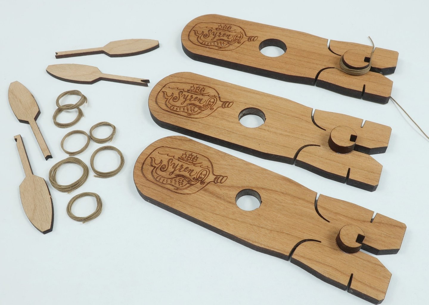
The SYREN ROPE COIL tool. For rope coils needed on deck etc as opposed to hanging on a belaying pin or cleat. The plugs on the tool are round and you can leave a one end to represent the rope's end. Three sizes of coils....Three tools. Its a variation on the design of the Syren rope hank tool. The step by step is a little different but even easier. You can see that I made the prototype from cherry this time. Either works just fine. I will have another step-by-step in a day or so for this tool. But you can guess how its going to be done based on the Rope Hank Tools. While making a bunch of coils I did change it up a little so that the tool would last well....forever, if you are careful with your glue.... Basically after the glue dries preserving the coils shape, it is removed from the tool before you have to use a sharp #11 blade. Then just use your blade to cut off the excess line on your cutting mat. DUH!! So the tool itself wont get damaged at all because there is no need to cut on it. Its funny how once you actually use these tools to make a crap ton of coils and hanks you just figure stuff out. The same can be done with the Rope Hank Tool. It really only takes a few minutes to make a rope coil. Not that I want to over-sell you....but the other thing I realized while making coils was to use two tools of the same size. While the glue dried on the first coil and it was set aside...you can start making another coil on a second tool. Just in case you want to buy two sets of tools. Going back and forth you can really get an assembly line going!!! I made a few below with varying amounts of wrapping and used two of the tool sizes I think in this photo.
-
Remember you can buy the complete kit here!!!! https://portlandscaleshipco.com/product/hms-neptune-1796-capstan-model-kit/ And join the group build completely for Free. Here is a link to the group build....start a build log and enjoy the project. https://modelshipworld.com/forum/175-project-build-logs/ This is a fun and really quick project. Thanks to JJ of Portland Scale Ship Company for making the kits available. Chuck
-
Try contacting Kurt or Mary. They might be able to help you out. They may be able to just give you their paypal address so you can skip the sidebar box all together and send it direct.
-
And just to add..... I agree and will be doing just that. BUT, this is also already available. Plans for the Cheerful are available to buy on my store and the monograph chapters are also there as a FREE download. I just sold a set and it reminded me of our recent discussions. AND...even for larger projects like the Winnie, You can pay just $15 and gain access to all of the plans and monograph chapters along with any templates etc as a download. So at least these two projects are available still for a small fee. Almost free in fact. And should you need to buy any parts that are difficult for you to make like the cannon or carvings....those are actually available too. So you have the best of both worlds. Just check out my website for the Cheerful or join the Winnie group project here. Chuck
-
Top right hand corner of the forum. Under the magazine cover.
-
Its fine keep going with posts about your models. Both models are looking great so far. Chuck
-
Its possible but these are really meant to be disposable or have a limited lifespan...they wont last forever as you cut away the loose ends and secure your hanks with glue, etc. They will probably get messed up a bit. Some people will have them last longer than others based on my observations over the years, LOL. Hence why 3D printing them was too expensive an option. But they will last for a few hundred coils if you arent messy with the glue and a terror with a sharp blade. You can just toss them and buy another set once they are used up. They are cheap at $12 for the 3 of them. Basically 4 bucks per tool. So they dont have to look pretty. Chuck
-
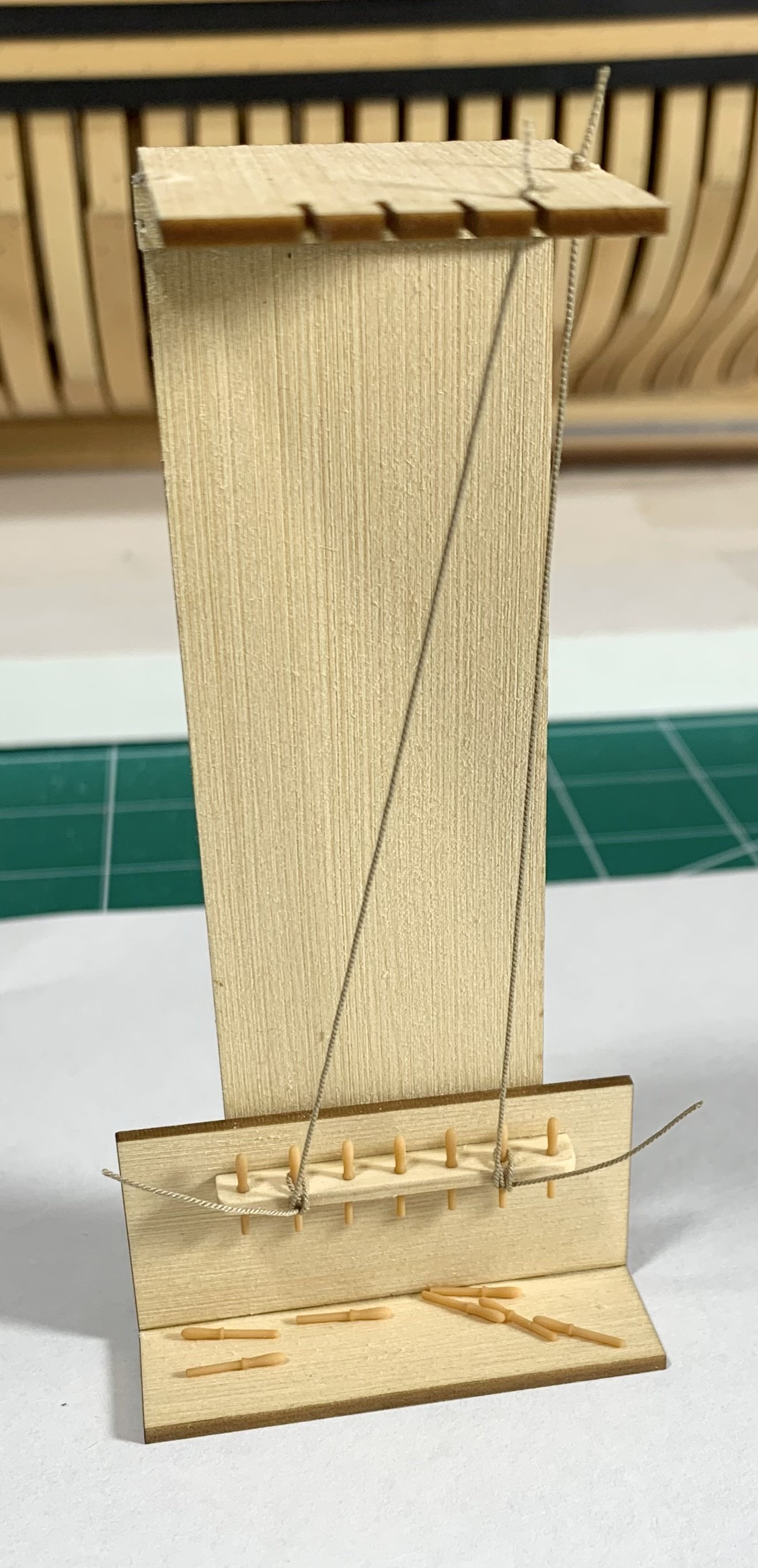
I am still nursing a bad FLU and Sinus infection. I have to add it to my site and will reopen at some point today or early tomorrow. This has been a bad flu season. It has been a couple of weeks and I still feel like crap. But I got bored and decided to finish the design for the ROPE HANK TOOL. I cant just sit around and watch TV, LOL. This tool is a result of an antihistamine high and dizzy dreamlike vision. It just came to me. It is so simple its almost stupid, LOL. I was trying to prepare for a tech session I am doing at our next club meeting. "How to Belay a line to a cleat or pin". So after using the traditional method of making a rope hank I just said to myself there must be a better way to do this consistently and quickly. So now I have a little mock up to show how to belay a line and this tool to demonstrate how to make a Rope Hank. My club will probably do a lunch where everyone gets these and gives it a try.

-
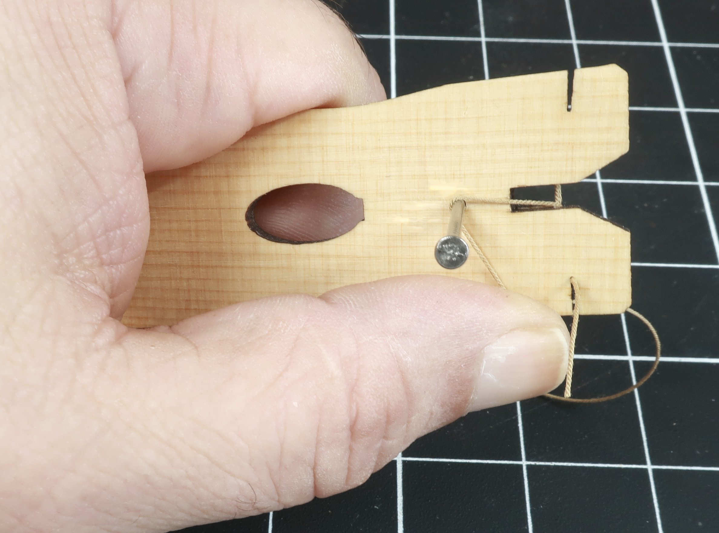
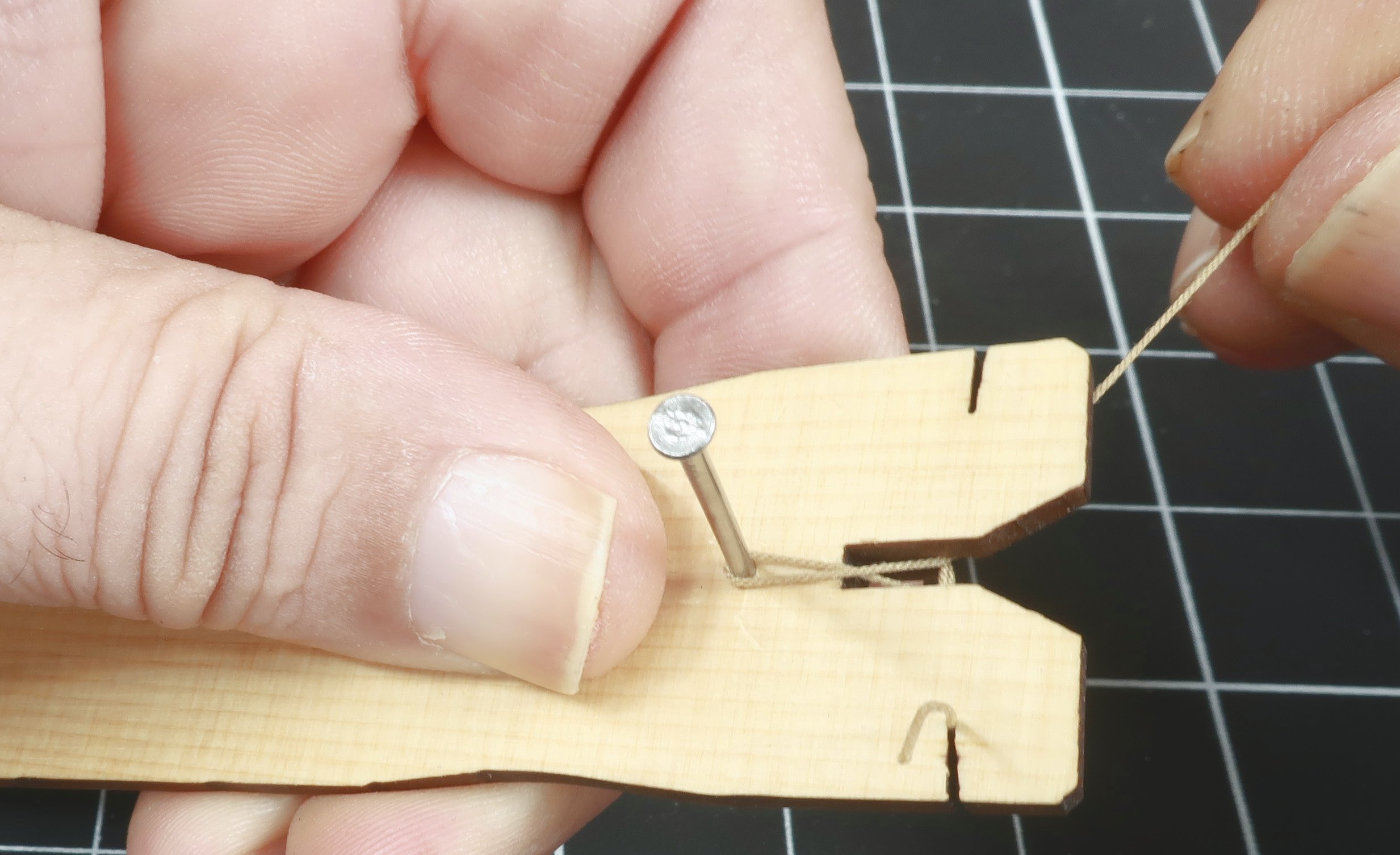
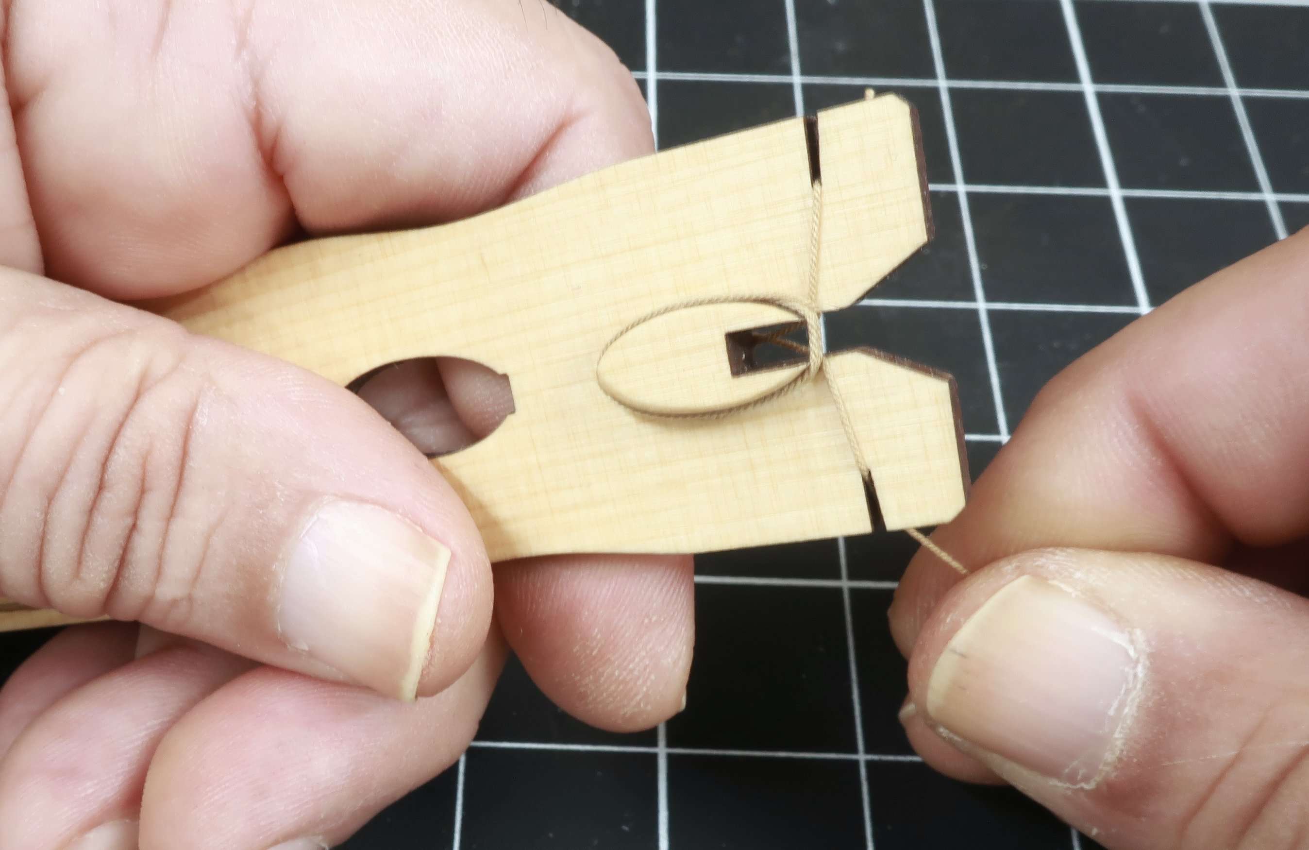
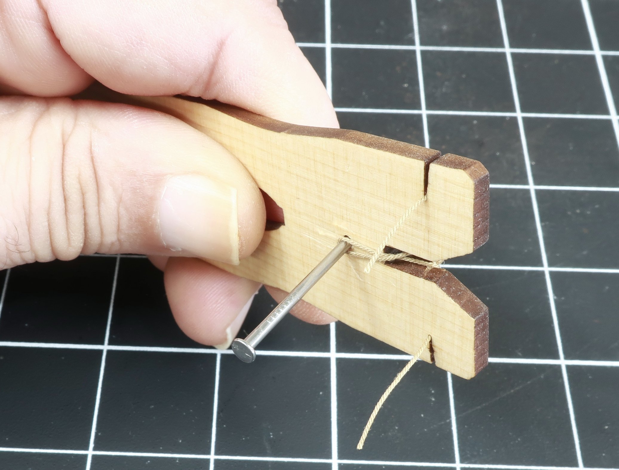
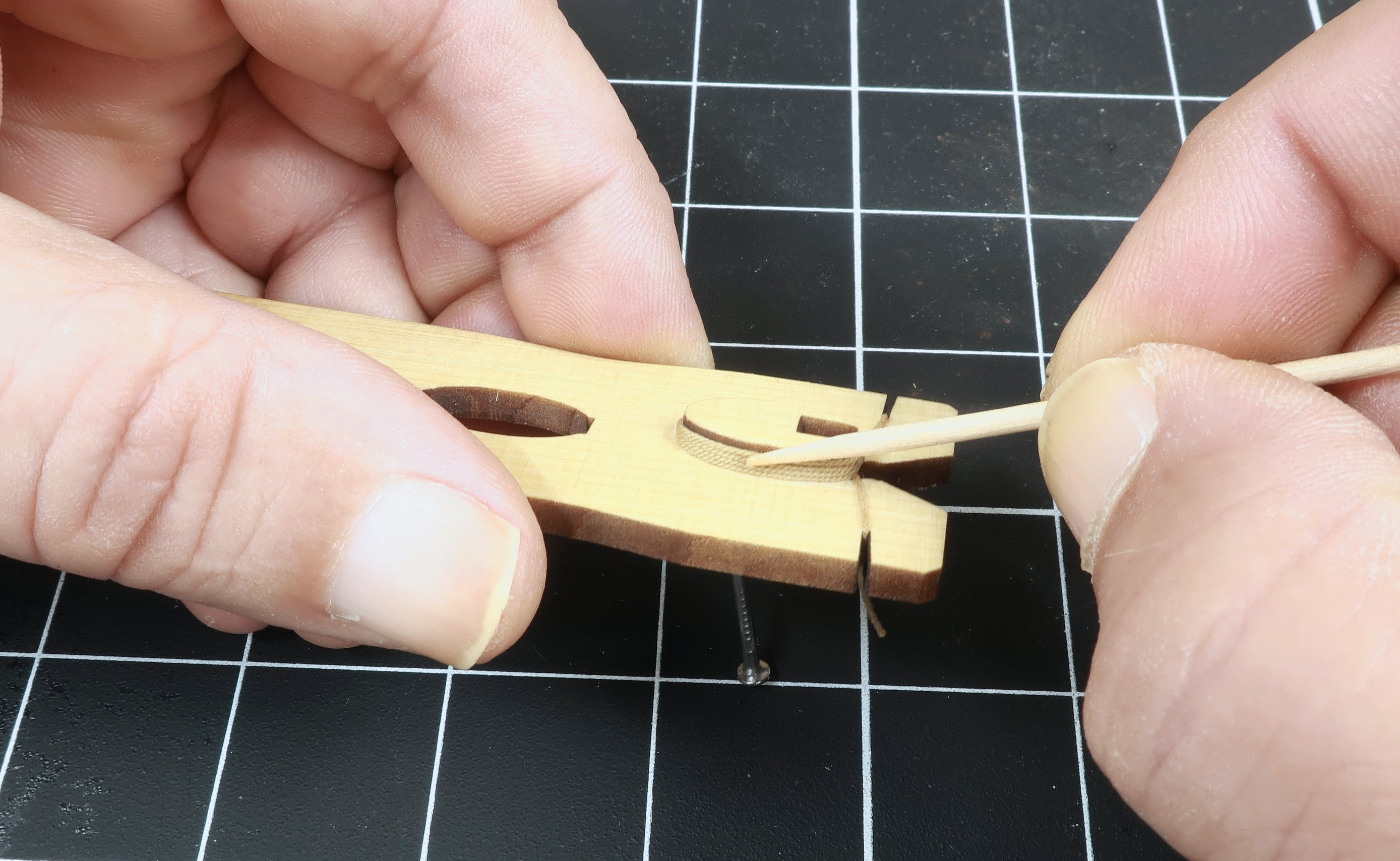
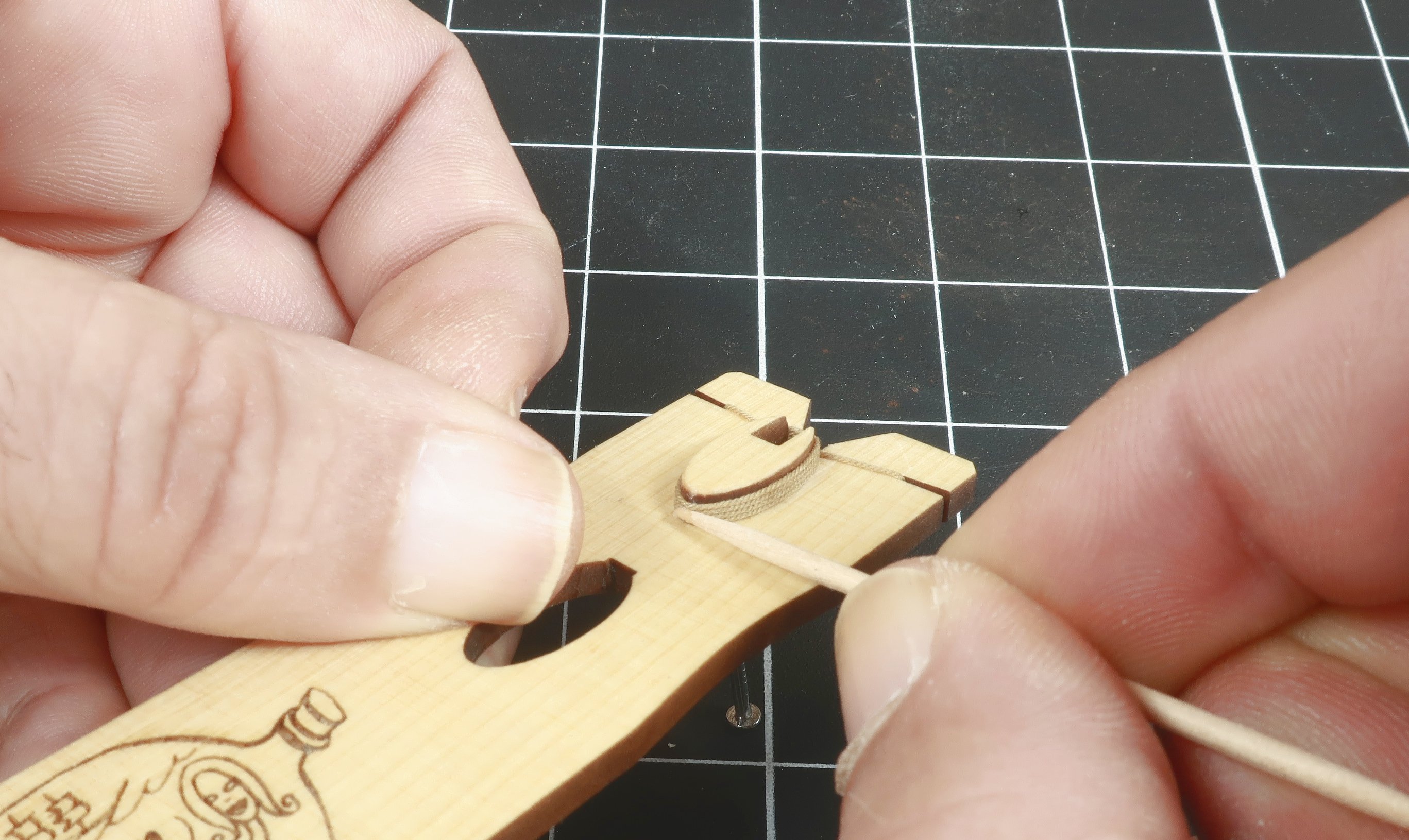
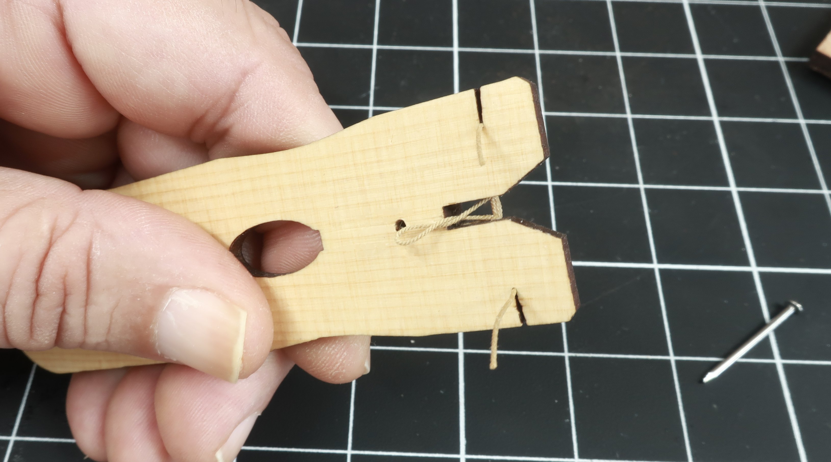
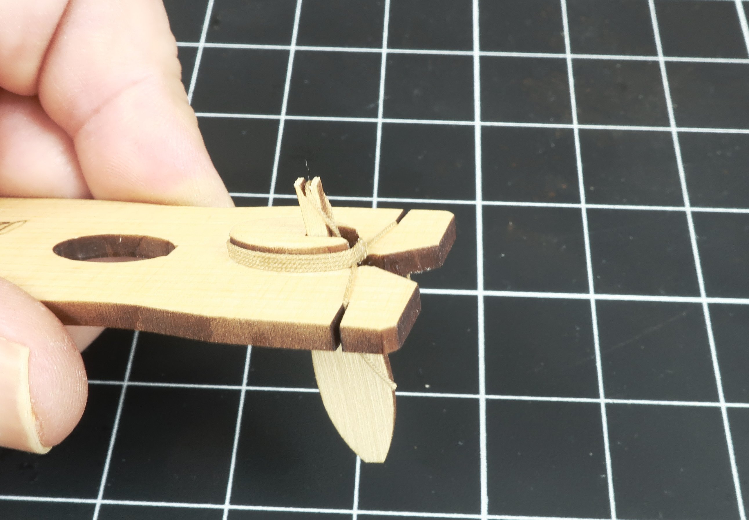
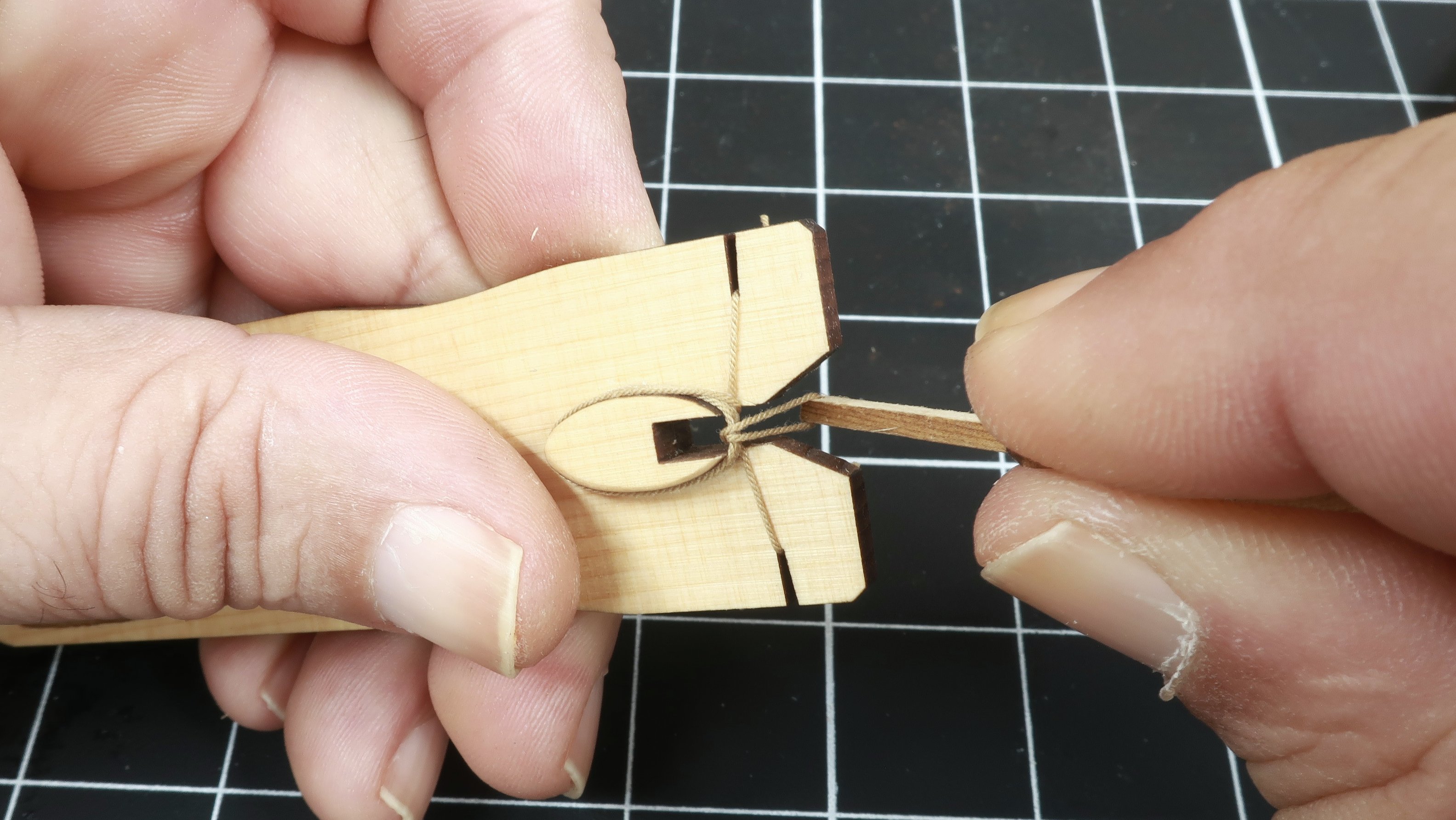
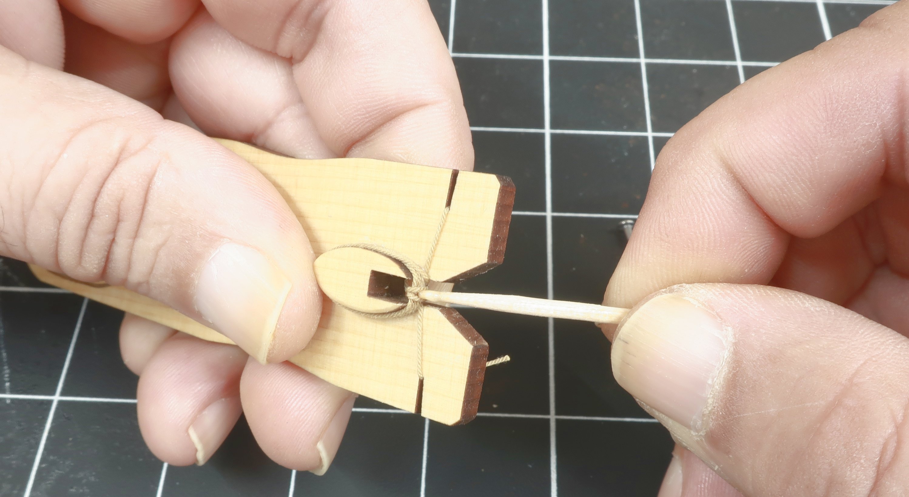
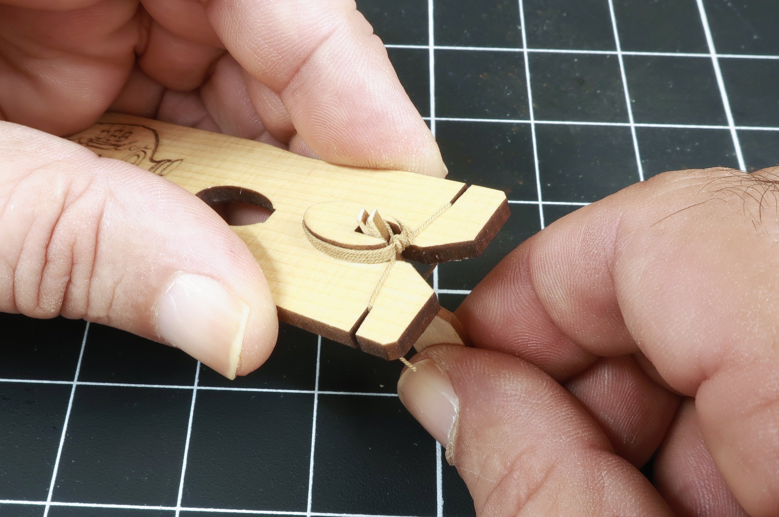
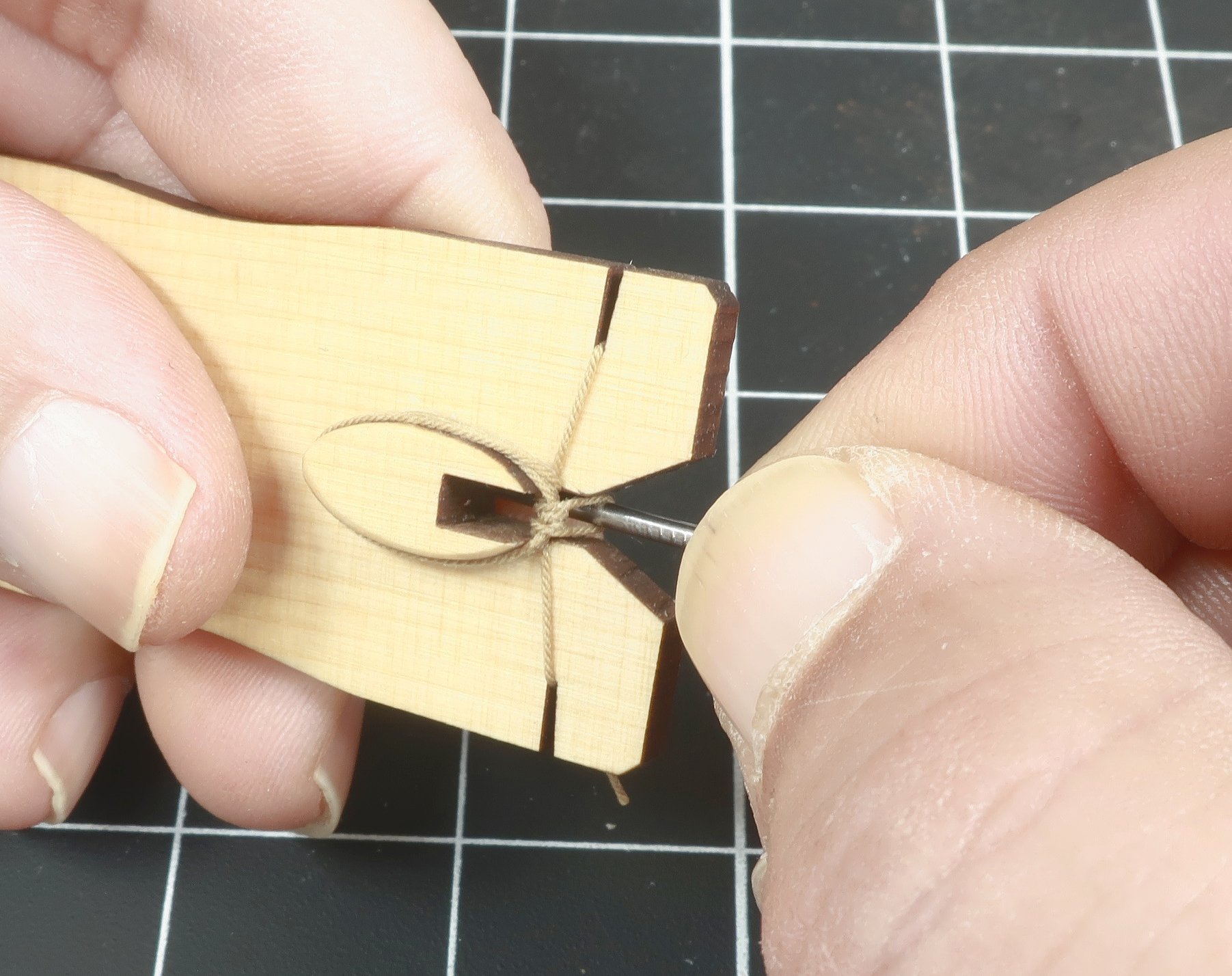
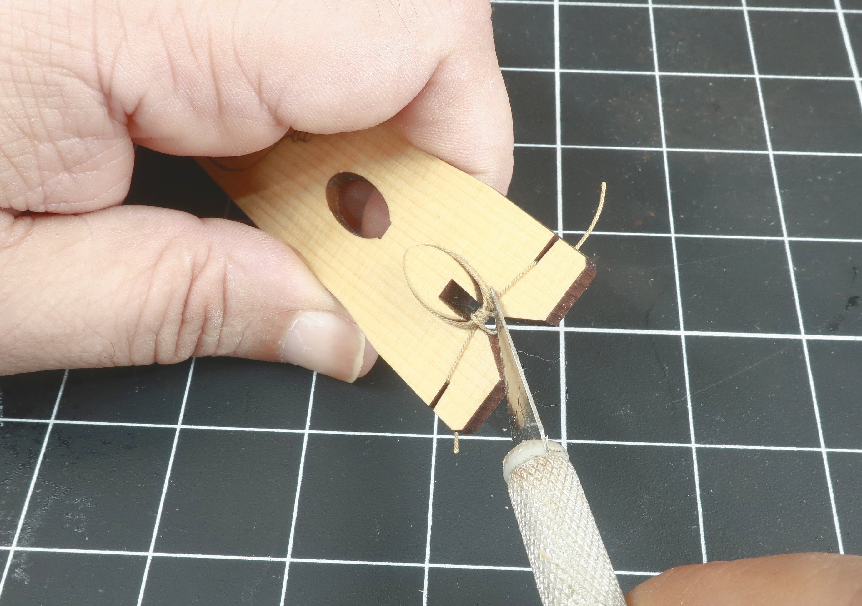
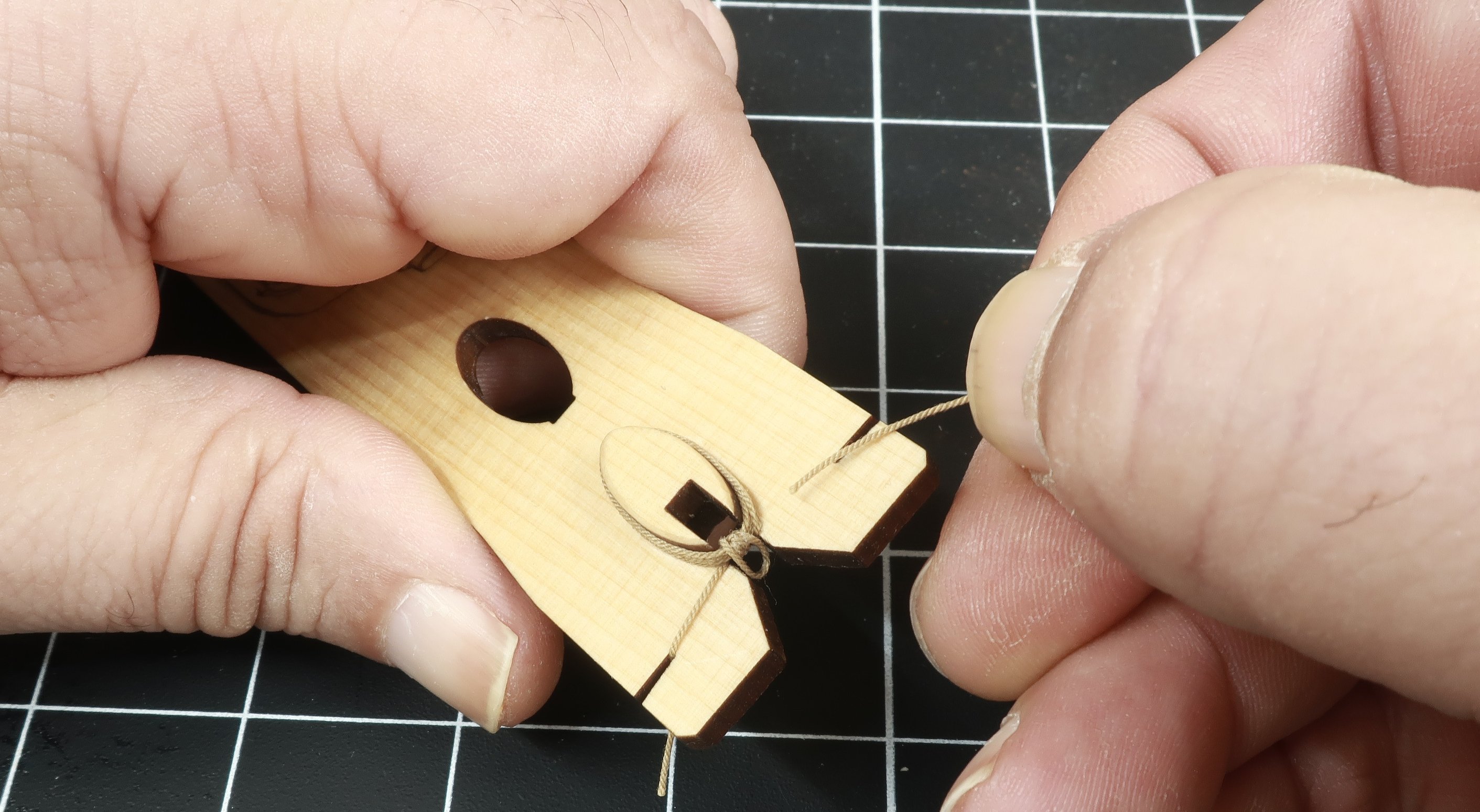
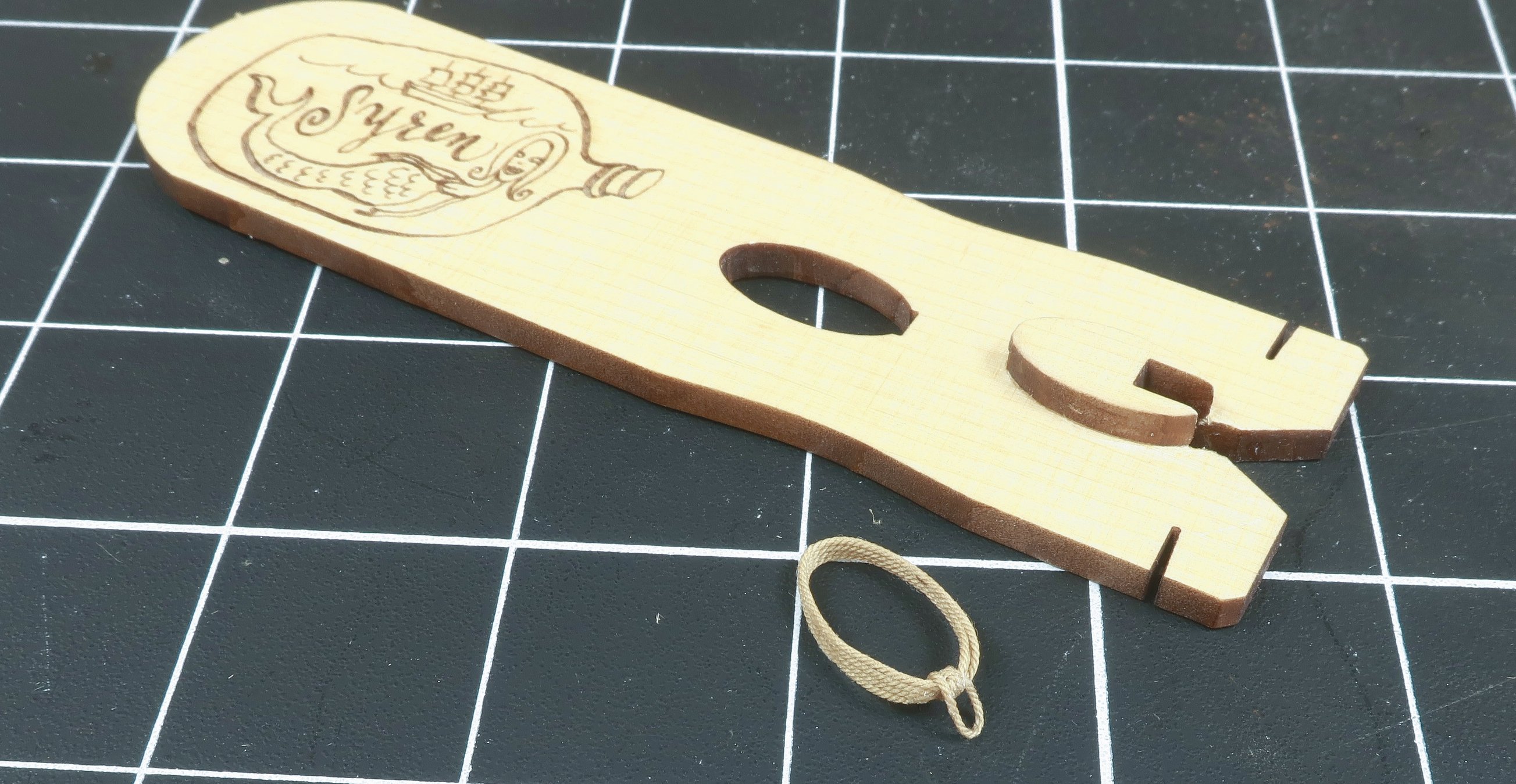
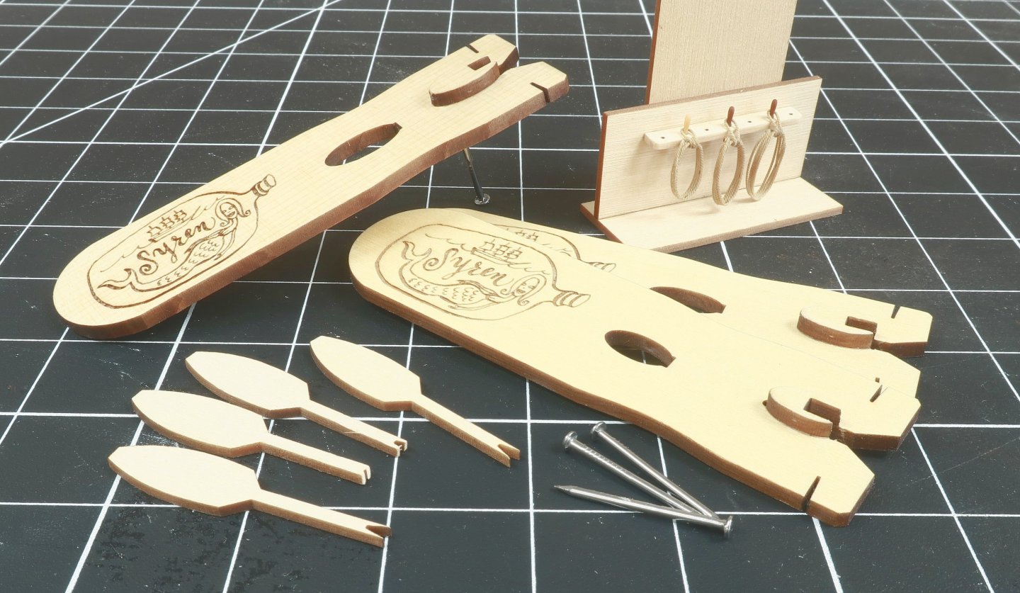
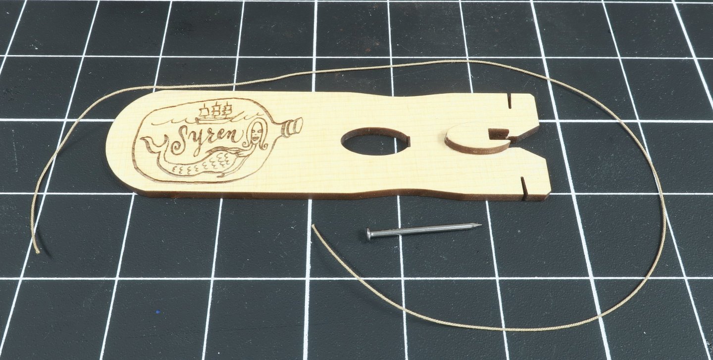
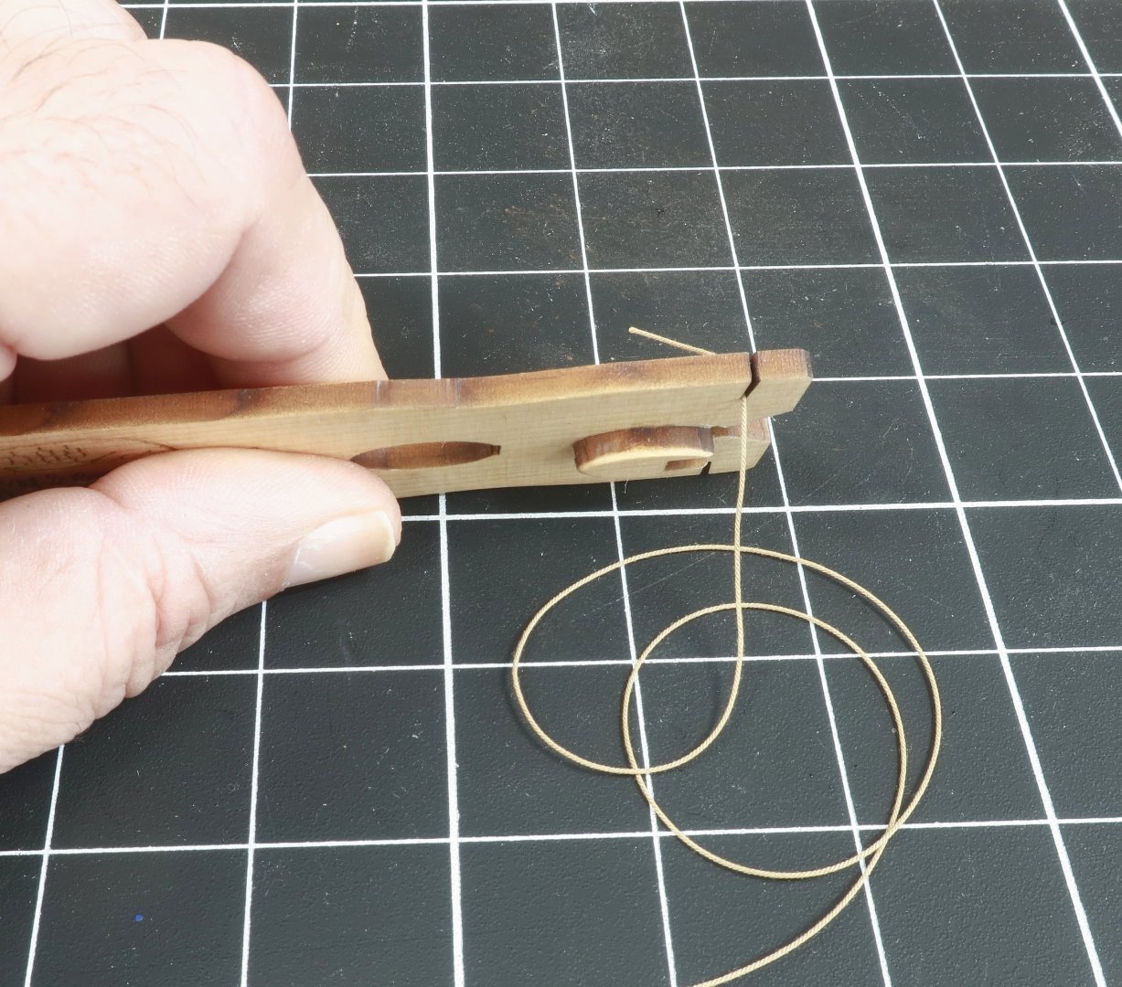
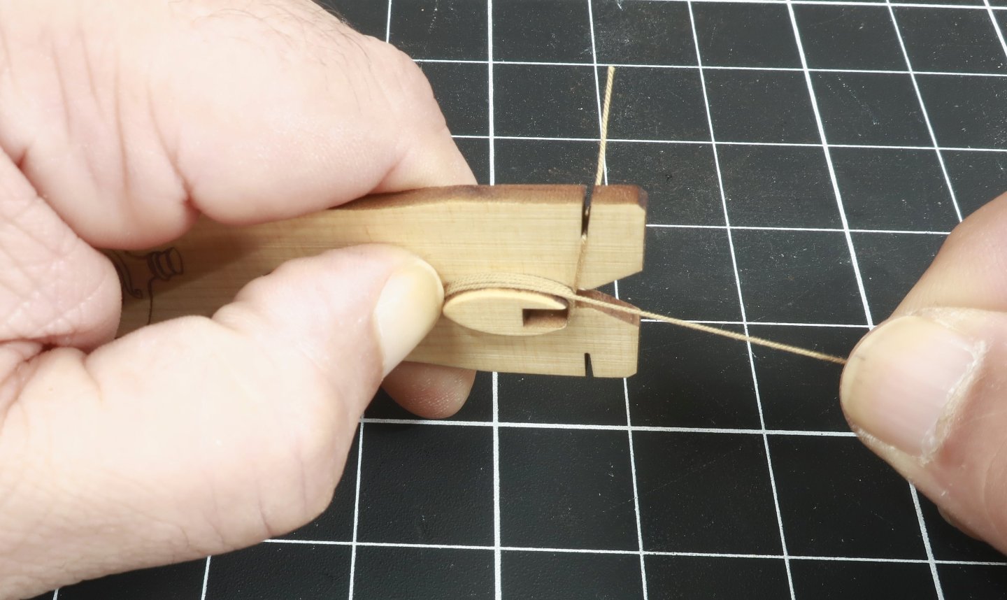
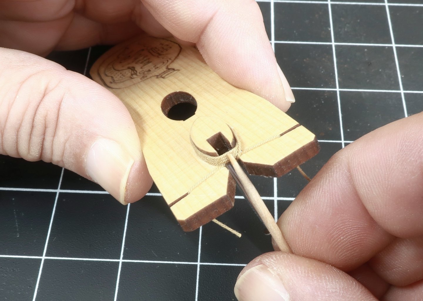
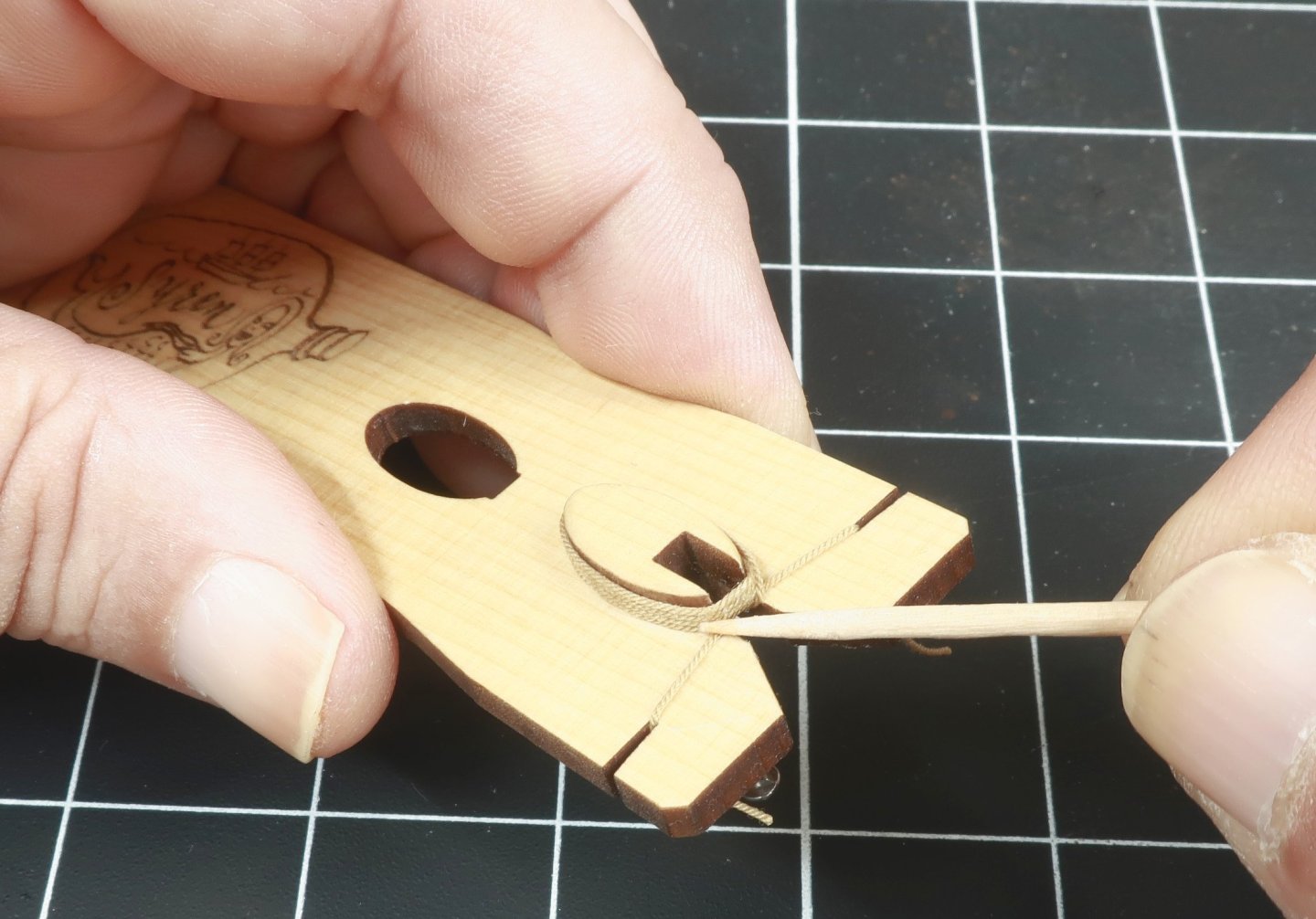
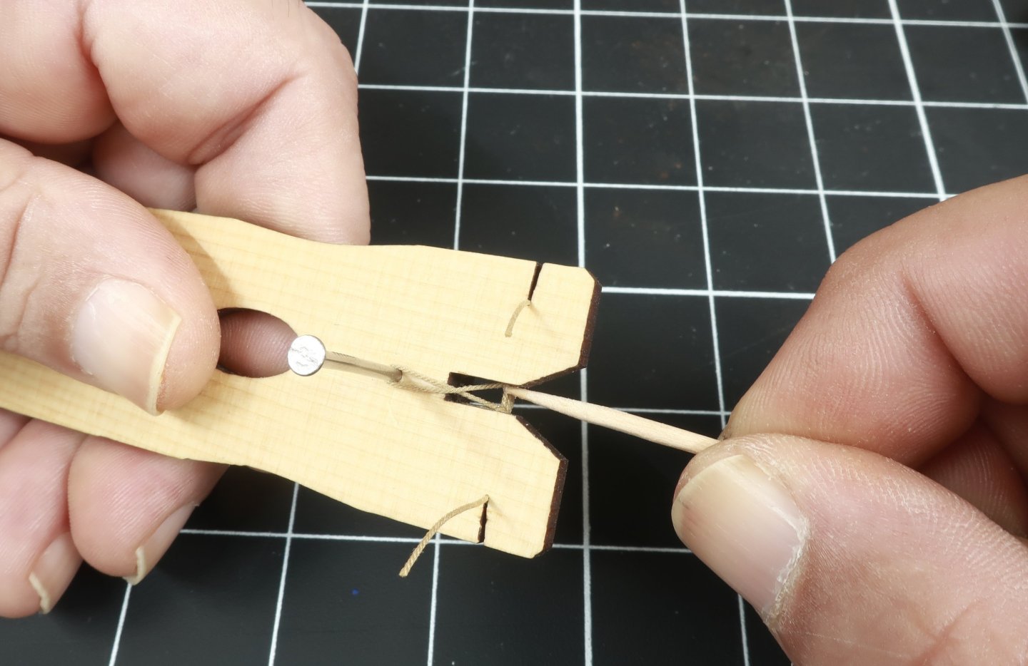
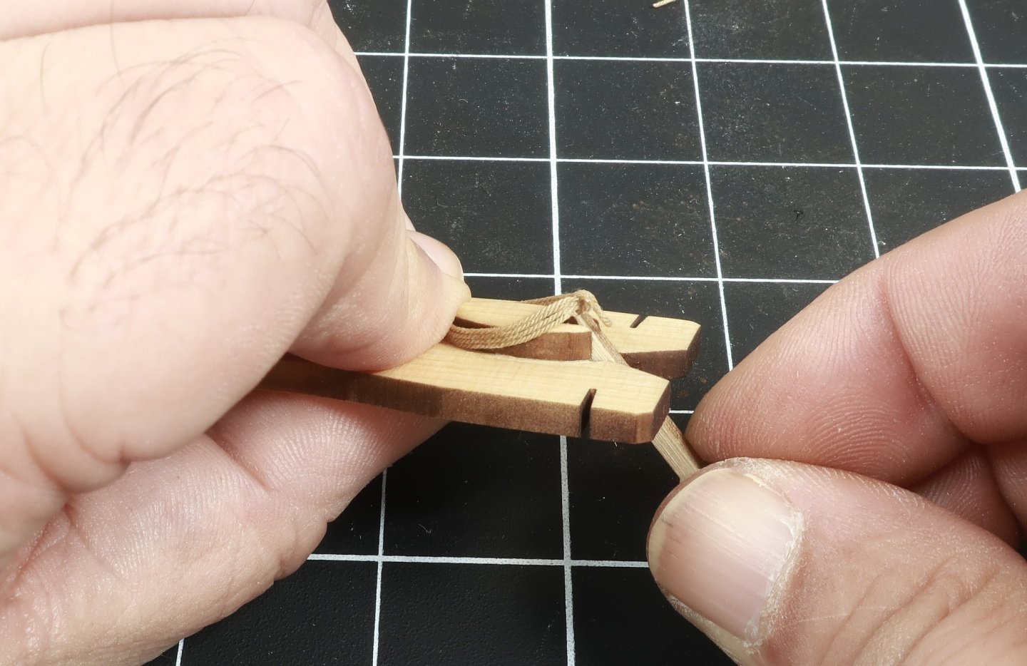
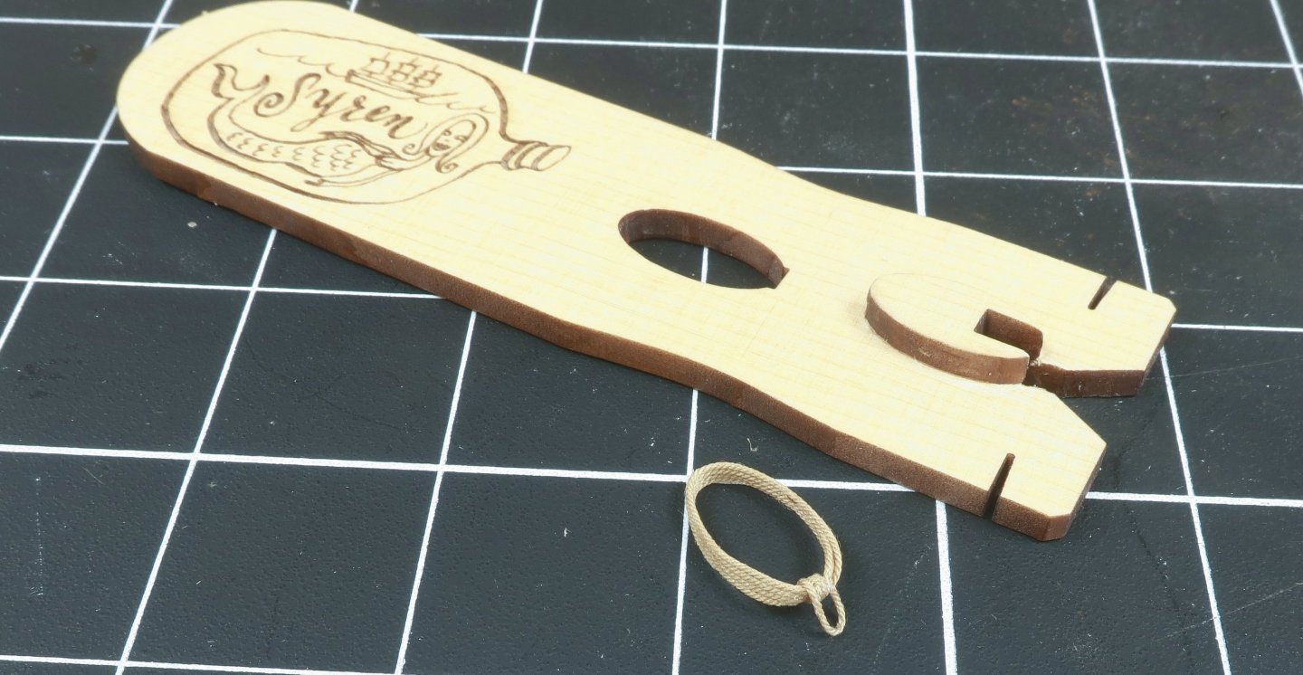
Introducing the SYREN ROPE HANK TOOL You will get three tools to make three different size Hanks. These produce hanks to be neatly placed over belaying pins and cleats. And yes another tool is forthcoming that will allow you to easily make round rope coils to be placed on deck, for examples for gun tackles. This HANK tool produces elongated coils to mimic the correct shape when hung as would be effected by gravity. Some assembly required. Its really simple. Just glue the small button or coil plug to the top of handle. There is a laser etched reference to make placement easy. I did sand the char off the top face and back of the handle. But that's it. There is no need to remove the char from the edges. Once glued up...I applied a coat of Wipe-On-poly. Lastly I rounded off ...or just knocked the sharp edge off the top edge of the coil plug. Not much but just to soften it. The small nail will be needed later...keep it handy but it is NOT permanently positioned. Now you are ready to make a rope hank...Just grab a length of rope. I am using Syren .018 rope which is common when rigging a ship with ropes belayed to pins or cleats. Just stick the end into the slot to secure the rope on the left side....NO GLUE. It will stay just fine. Then wrap the rope around the coil plug 3 or 4 times. I would NOT go around more than for times although you might want to try 5 times with thinner thread. You dont want these hanks to be too heavy and clunky on your model. TIP...I found it easier to rotate the tool rather than wrap the rope around the plug. It actually helps prevent the rope from twisting as it sometimes does when you wind it around the plug. As I was rotating the handle I just instinctively pressed each wrap down so they were neatly pressed together with no space between each wrap. Nice and neat. Go in a clockwise direction. Now its time to take that handy little nail. Insert it into the hole on the back of the tool. Just press fit the nail into the hole so it is secure. Take the rope through the notch to the back and around the nail. Counterclockwise. Easy-Peasy. Bring the rope up the other side so it crosses over and then bring it back through the notch to the front of the tool. Then take the rope and just stick it in the notch on the right side of the tool to secure it. Not too tight but snug as you can see. This is what it looks like on the back side... Now I am using polyester rope from Syren so I must use CA to secure the rope hank in a few spots before moving forward. Not a lot as you dont want to glue it to the plug . I am using medium CA and applying with a toothpick. Not a lot remember. Just a little goes a long way. If you are using Cotton rope you can use watered down white glue or Elmers. I start by added a little across all four coils at the top within the notch. Then a little bit where the two ends touch the bottom coil. This needs to be secure because we will be cutting these off soon. You can add a little on each side across all four strands too. Not a lot!!! Wipe it away to prevent any staining or shiny spots. The very bottom too!! And lastly, flip it over do the bottom. DONT glue the hank to the plug!!! Next you can pull the pin.... Using one of the four small tools included or whatever you find easier, even a tweezers or bent wire...you can experiment with whatever is easier for you, I found the tools worked just great. There are different style tips. Push that loop from the back of the tool through to the other side....the front. Push it through under the rope coils. Then grab it and pull it over the top of the hank. This should be taught and the tighter you pull it towards the back the longer this loop will be in the end. You can adjust how tight depending on how long a loop you will need to hang the hank on your belaying pin rail or cleat. Add a drop of glue... Then go around a second time. Its not difficult at all. Use the nail or whatever to pull it towards the back. Adjust how tight to make this final loop as long as you need it. If you want a shorter loop, dont pull so tight. You get the idea. Add more glue to the top to secure that loop....and then you can start freeing your hank from the tool. Use a sharp NEW blade to cut the loose end. Cut is as close to that bottom coil as you can without damaging the actual coil. Discard that loose end....a nice clean cut. Repeat on the other side. Then simply lift the finished hank off the plug. Hopefully you havent over done it with the glue. You shouldnt have any glue that really touches the plug or handle while you did all that wrapping. If you were successful, you should be able to push that hank off very easily from the back side. Use one of the four small tools provided as shown below. And thats it....congrats you did it. Now repeat because you will need a lot of these. It goes quickly and makes some really neat rope hanks. Thanks for watching.


-
Coming Soon, if there is interest.... Syren Rope Hank Tool Make three different sizes of rope hanks. I have been using similar for years but decided to tweak my design so others might want it, and it would be easy to mfg. Originally I was going to 3D print this but that would take a while to do and be very expensive. It used a lot of resin. I found that just laser cutting a simple design worked even better actually and is very cheap. After many design changes I have finally finalized my design... Its very simple as you can see. My guess is you will see quite a few copies really soon, just remember where you saw the original after it shows up on Temu and on the ZHL site, LOL. Patent Pending!!! I will have a step by step after a take some photos of the process. Make perfect rope hanks every time!!!!

-
Alan…i do in fact realize that. Thats why some of my future models will be released and open- sourced here on MSW for free. So folks can just build them from scratch. Much like the original group project here Alan that you remember…the brig Syren. I dont need the tens of dollars for any practicum and plans. So I will just post them for folks to enjoy. So yes there will be a bunch of those. I named my company after that first project, LOL…so it will be good to get back to my roots with those.
-
Yes it will, but it wont be mfg by me. I am currently preparing all the files for the Winnie for hand-off to JJ. Its a slow process. I will be doing one kit at a time with JJ and Chris as they find time to start making them. I am grateful to both for agreeing to make them available and I know how much work is involved in doing so. All of the Syren projects and kits will find a new home and still be available. But it will take time. And before anyone asks or starts any unfounded rumors. I am still making fittings and blocks and rope and have many many years before my Syren retirement. So no worries. I just cant possibly continue burning the candle at both ends and doing it all myself. I am just stopping the mfg of my kit projects…especially now that Modelers Sawmill is no longer producing the wood for me. I am too tired to continue working 7 days a week and 12 hours a day and now having to mill my own wood on such a monumental scale. Maybe I can finally start taking weekends off ,LOL. This includes Speedwell which will be available for folks that that thought they missed out on a chance to build the Syren Kit. That kit project will be handed off as well in addition to any new models in the future. I love designing and building them…but mfg them afterwards is no longer in the cards for me. So i will pass along the projects for free as I complete them in case there is any interest from all of you who also wish to build them. Chuck
-
Just beautiful work…and Happy New Year