Chuck
-
Posts
9,711 -
Joined
-
Last visited
Content Type
Profiles
Forums
Gallery
Events
Everything posted by Chuck
-
 Here is a downloadable PDF full size of the rigging plan. This is without sails for those who wish to rig it this way. I have omitted the sizes of ropes and blocks as this will all be explained in the instructions. Its a simple rig and this way those notations wont crowd the paths of the rigging on the plan sheet. I am releasing as a download also because I know there may be folks who would prefer not to pay for a masting and rigging package especially after so few items are needed that you might already have. I will do the same with the sail plan. This will hopefully help those in other countries where the shipping would be ridiculous to send a plan sheet and mast material in a mailing tube. But I will offer it of course for those who still want to buy all the parts in cedar and use my rigging blocks and rope which will be part of the rigging kit. let me know if you have any questions about the rigging plan. The mast blank is 20" long and will be expensive to ship internationally even though its very light. 26ftlaunchsheetonehalfsheet3.pdf
 -
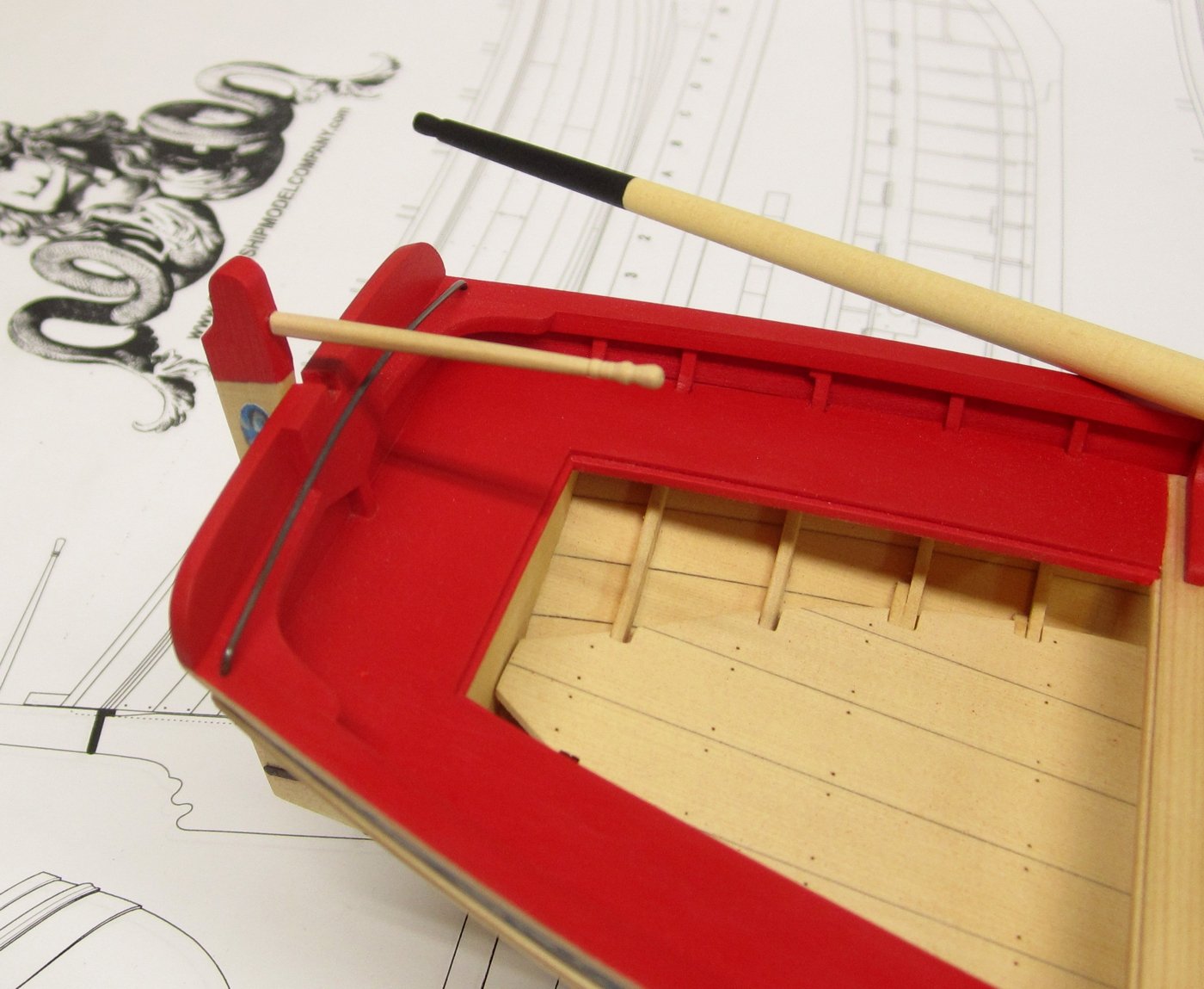
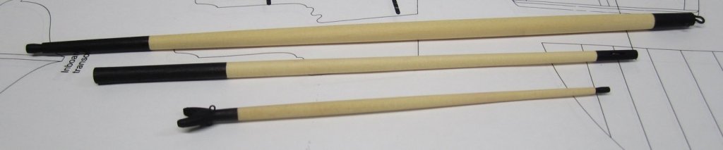
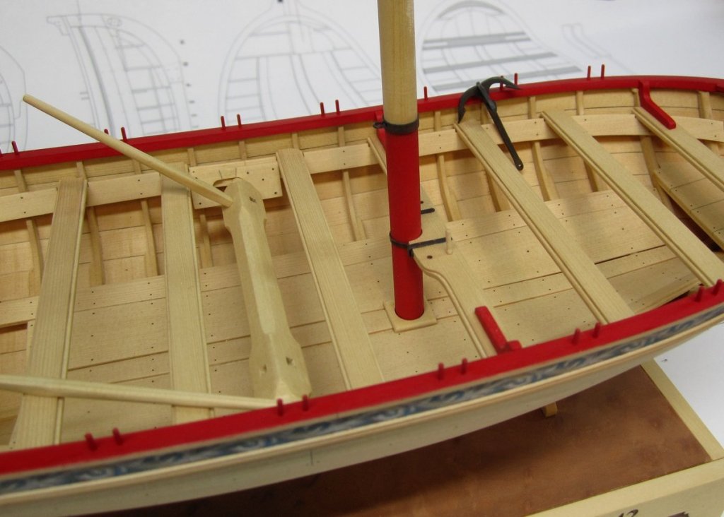
Time for sticks and strings!!!😄 I finished up the boom, gaff and bowsprit today. Nothing unusual to report and its just more of the same. Square stock was rounded off like the mast. The gaff has laser cut jaws that need to be attached. Then a few eyebolts were added to follow the plans. The boom has a hook made from 18 gauge copper wire (blackened) on its inboard end. There is also an eyebolt. The bowsprit has a sheave on its outboard end which is typical and it was simulated the same way that was used when making them on the mast. So now I am ready start with the strings. I added the horse under the tiller which is typical for the period and as has been discussed numerous times. This not only follows the two contemporary models that are fully rigged but also contemporary rigging plans. One great example can be found I believe on page 80 of mays book. The horse was made from 1/16" brass rod (blackened). And lastly a photo before I start rigging. The Boom and Gaff will be rigged first while the there is more room. Then the shrouds and stays will be done afterwards. I have also uploaded the rigging plan (without sails). Chuck


- 421 replies
-
- 16
-

-

-
- medway longboat
- Syren Ship Model Company
- (and 1 more)
-
Yupp!!! But this is all stuff that just wouldnt look right on a model in my opinion. I m sure it was all used, but its just as important for a model builder to decide what not to include in order to make a better model. It would just look very odd indeed. As I have mentioned several times previously...the "kitchen sink" method of model building is not my thing. But it does open up possibilities for others if they like that sort of thing. Especially when there is so much primary evidence of this stuff. The hard part would be getting enough details of how these items looked to be able to model them properly however.
- 574 replies
-
- 2
-
-
- cheerful
- Syren Ship Model Company
- (and 1 more)
-
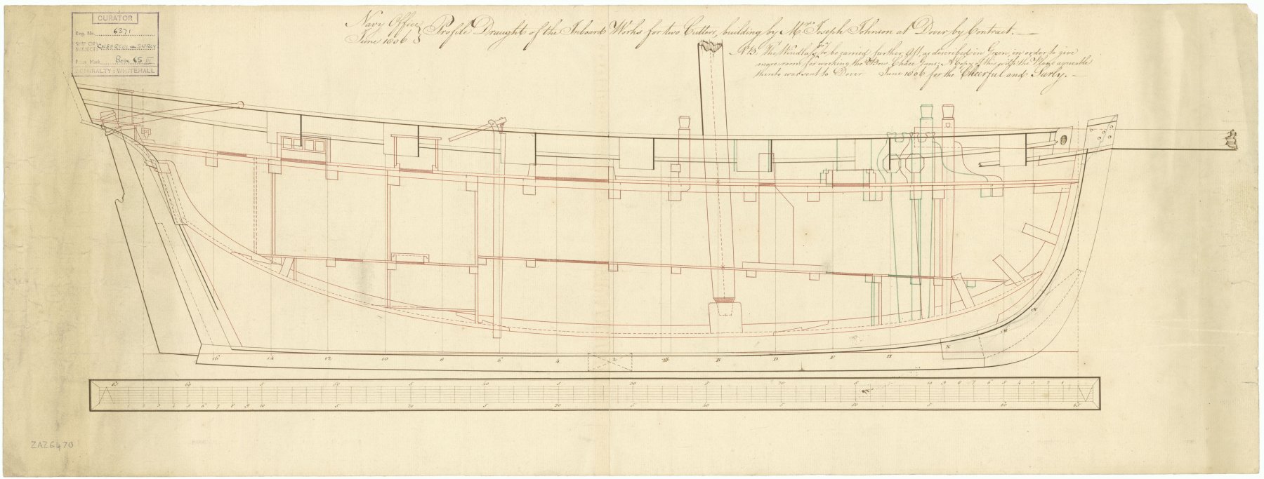
I would agree that the two heads are a bit much but if you take a look at the contemporary model for Surly it does show two heads at the stern. This is what I used for my model. Its not a locker because it has a hole just like the Starboard side which would make for messy stuff keep in there if it was meant to be a locker. Those two other features you highlighted on the plan were also a mystery to me. But they are not the heads. I originally thought they might be for a portable mast that could be set up on either side of the boom. That they were wooden crutches with iron straps to hold the mast back there in position.....But thats just my guess. They would stretch across the two stern frames adjacent to the heads. I opted to just not show this feature. But they are also visible on the inboard sheer draft. There are quite a few unidentifiable weird things going on and depicted at the stern on this draft. I chose instead to duplicate the Surly contemporary model rather than guess what is going on back there. Check ot the other features........some crazy stuff.

- 574 replies
-
- 2
-
-
- cheerful
- Syren Ship Model Company
- (and 1 more)
-
Error in kit and asking for advise
Chuck replied to Ulises Victoria's topic in Masting, rigging and sails
Make an entirely new channel with the deadeyes spaced properly to avoid the guns yet still be in its original position. It should be easy enough to make. Just trace the channel and make new slots for the deadeye positions. Chuck- 9 replies
-
- 11
-
-
I use a brush to apply and a clean brush to wipe or buff it off afterwards. Use a cheap brush unless you want to clean them....I usually buy a bag of cheapo brushes for kids crafts and dump them when I am done.
-
Looks great Rusty....great to see the progress!!! 😊
- 152 replies
-
- 1
-
-
- medway longboat
- Syren Ship Model Company
- (and 1 more)
-
You are correct.....no char left is the way to go. More sanding
-
Nope...not too easily which is why I didnt do it. Chuck
-
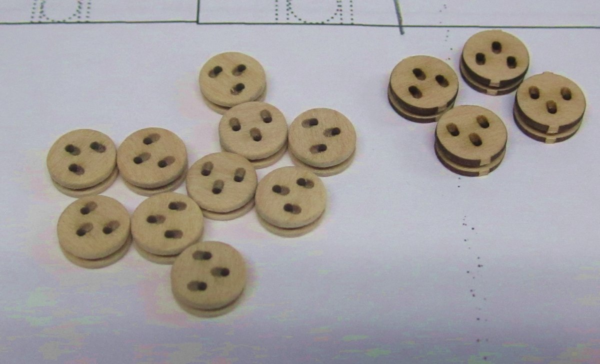
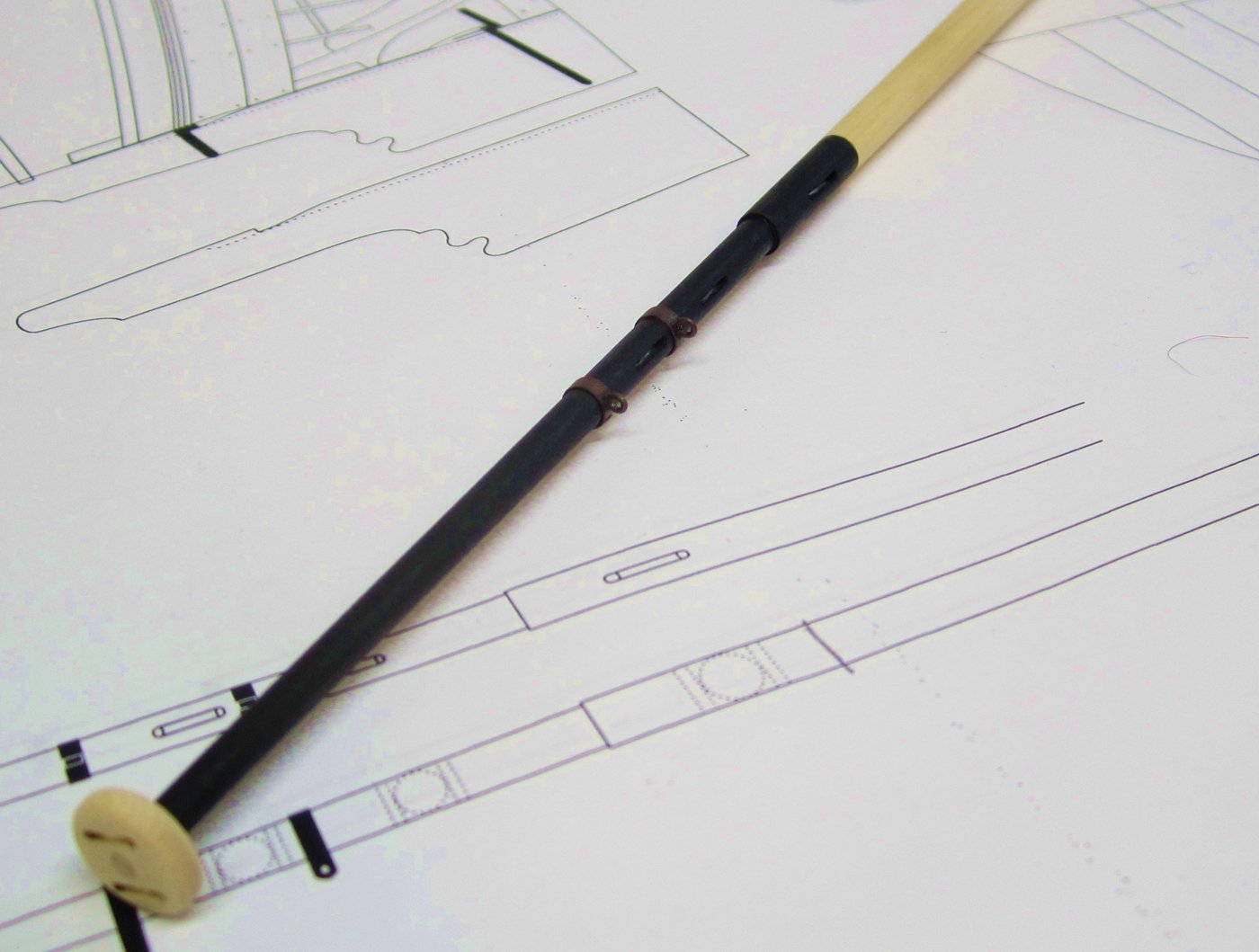
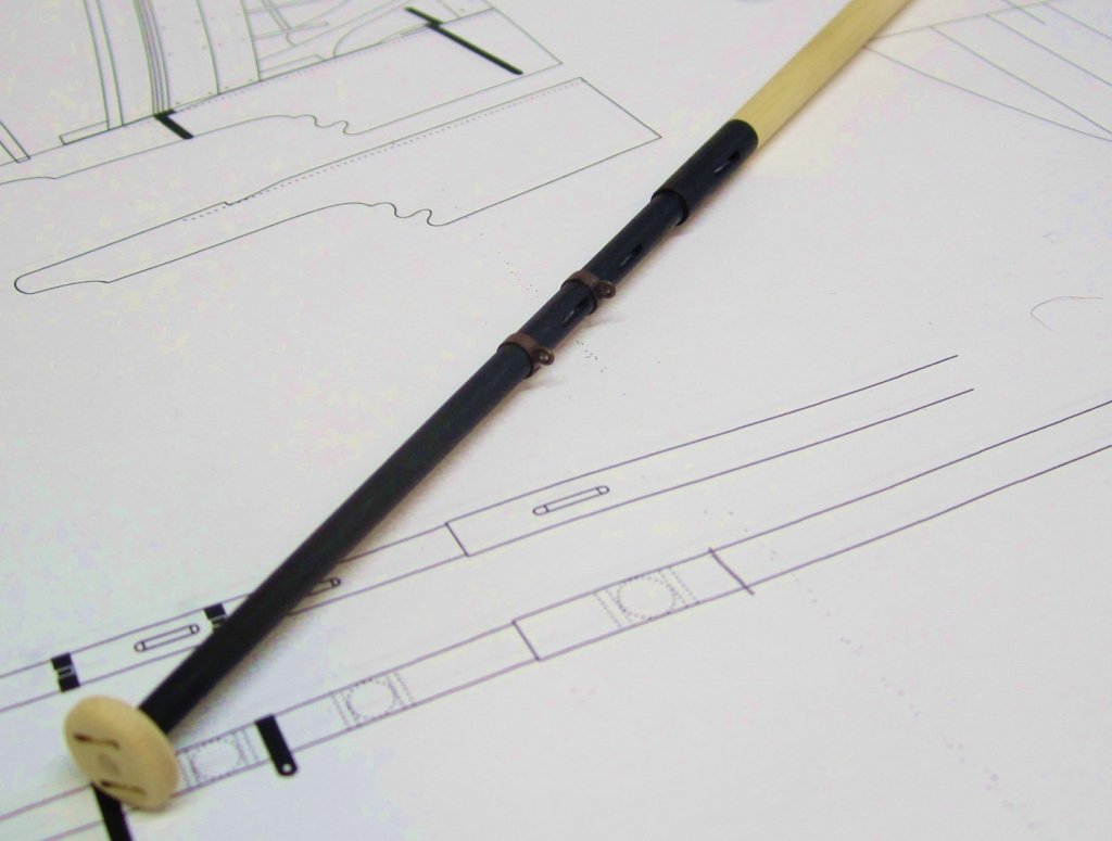
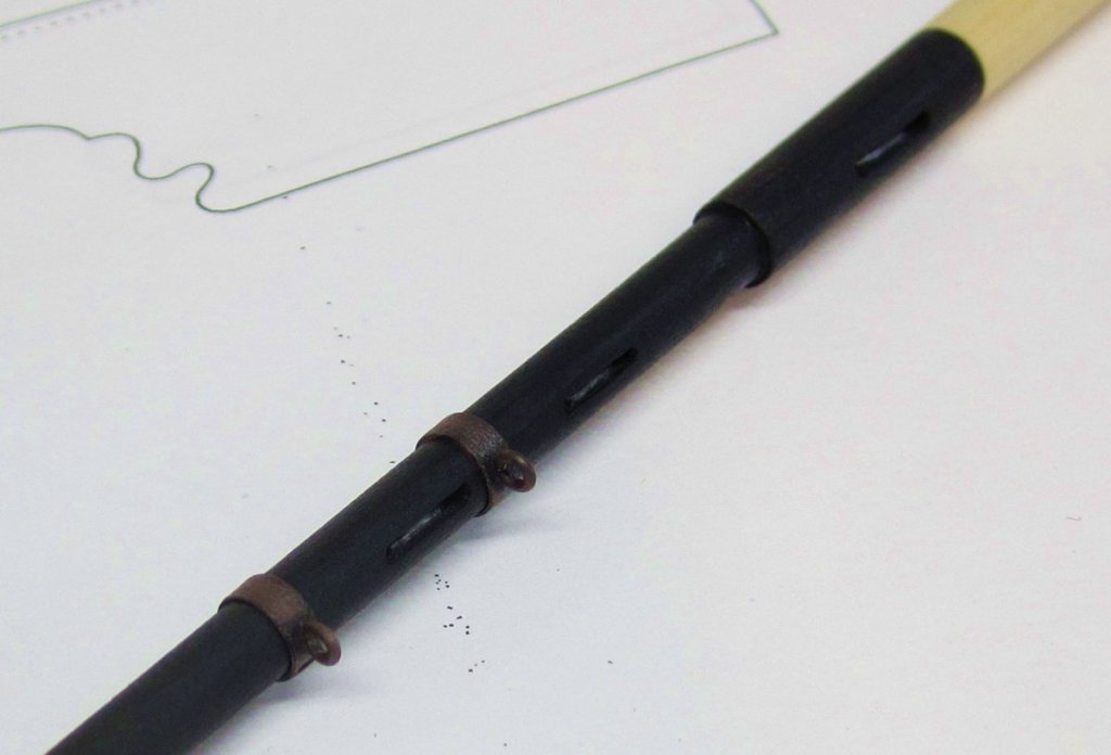
Continuing with the main mast. I painted the areas of the mast red or black to suit. Then I simulated the mast bands with black masking tape. The tape was cut into strips 1/16" wide and wrapped around the mast a few times to get the correct thickness. Before anyone asks how thick.....just until it looks right. Not too heavy. I wrapped around twice and it was plenty. Then I used some rusty brown weathering powder to make it look different than the painted mast and more like metal. I will only use brass or actual metal when absolutely necessary. In this case it isnt needed. Then I finally made some eyebolts using 22 gauge black wire. I drilled holes through the bands and inserted the eyebolts. I also ran some pencil over the sheaves I made on the mast to make them look different and stand out a bit more. and a close up view.... At the base of the mast, it was painted red up to the band there. This band was made the same way but this time 3/32" wide tape was used. The eyebolt was made using 20 gauge brass wire blackened afterwards. I cant find pre-blackened 20 gauge wire. The mast isnt permanently stepped yet but the mast is now completed. I will now make the boom and gaff.... I also made the 7mm deadyes that we will need for the model. These are just like the kits I offer. Three layers are glued together.....then I remove most of the char from the outside. To finish them up I throw the in my block tumbler to soften and round off the edges. Not to long though...or they will get funky. These are boxwood and not cedar. The cedar is too soft to make these. You can see four deadeyes that were released from the spru with no sanding or laser char removal. The other group is ready to go but no finish has been applied yet. Any questions please dont hesitate to ask.

- 421 replies
-
- 22
-
-
- medway longboat
- Syren Ship Model Company
- (and 1 more)
-
Its up to you....Whatever you are more comfortable with. I tapered them ahead of time but then touched up the entire assembly afterwards.
-
Have fun with project....looking forward to seeing you get started.
-
It wont really cause issues. They play on the baseboard slots was done on purpose. Just do your best to center them. When you fair the hull it will make up for any small issues. Keep going...... Chuck
-
Really Nice Ben....
-
It looks very good indeed!!! You finished all the pain in the butt stuff. Its all fun stuff from here on out. Also a lot quicker.
- 574 replies
-
- 3
-
-
- cheerful
- Syren Ship Model Company
- (and 1 more)
-
Just buy a whle roll of every size available on ebay. Sunset amnesia I believe is the name. Its great stuff. And cheap.
-
Sunset/Amnesia brand. I buy it on ebay.
- 421 replies
-
- 2
-
-
- medway longboat
- Syren Ship Model Company
- (and 1 more)
-
OK.....you guys are going to laugh your heads off!!!!! All of you who bought kits already should have two of planking sheet "P". Of course due to a typo on my materials list where I didnt place the (2) next to P.....means all of you got just one sheet "p". Because I of course followed my own mistake on the materials list. I must be tired. So next week I will ship one planking sheet "P" to every person who bought a kit so far. No biggie. Sorry for the mix up. Unless you got 2 sheet P's because if I had extras I just stuck them in some kits. Please let me know so I can save on shipping you a new one needlessly. If by chance you dont want to wait because you are planking right now....you have more than enough room on the bottom of each 1/32" sheet to cut those planks. But if you can wait....you will soon just get a sheet of planks in the mail. I will try and ship them all next week......argh!!!! Sorry again......Good times for me. Stupid mistake....
-
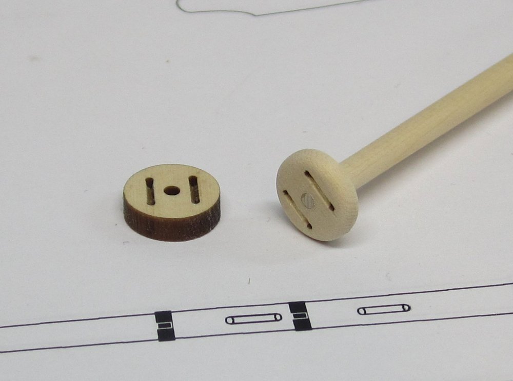
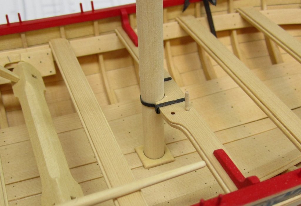
I will add it to the list.... I also managed to experiment with the mast parts. I completed the ball truck for the top of the mast. Its things like this that make you appreciate 1/2" scale. The ball truck has two sheaves for the flag halliards. These were laser cut and etched for you. But as you might guess, only on one side. So if you want, you can add the simulated sheave slot between the two holes on the bottom of the ball truck too. But in all honesty, I dont think anyone will see it. I did it anyway. You can see the unsanded version in the photo You need to round off the edges and corners on the top and bottom to make it look nice. I did this after I glued it on the mast. Its easy to rotate and twist the mast as you hold sandpaper against the ball truck to shape it. Make sure you orient the sheaves on the ball truck correctly when you glue it on top. They go parallel to each other for and aft....,one sheave to port and the other to starboard. I also stepped the mast but not permanently. On the contemporary models and in real life the mast would sit in a hole through the floorboards. This would have been a pain in the butt!! Lining up a hole for the mast in the floorboards even before you added the thwarts and just praying the mast would be lined up correctly. So my solution was to create a thin mast step instead. Its a little guilty simplification. Its basically a square with a hole in the middle for the mast. I rounded off the edges to make it look nice. Its only 1/16" thick. I placed the mast in position and in the mast step as the titebond was setting. Then I adjusted the angle and straightness of the mast to find the proper placement for the mast step. This was done before the glue sets so you have to work fast. The mast is set straight up and down with no aft rake......having said this, I did add an ever-so-slight aft rake because when I add the forward stay, I always seem to pull the mast forward. Knowing that I will probably do this yet again in error, I compensated for it by leaning the mast slightly aft. It should correct itself once I rig the forward stay which will pull it forward slightly.

- 421 replies
-
- 30
-
-
-
- medway longboat
- Syren Ship Model Company
- (and 1 more)
-
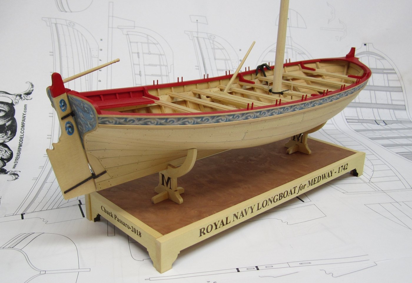
I am not sure. Maybe some folks dont like this and would prefer another type of stand. What I may do is just offer the stand and cradle parts as a whole separate mini kit for the project. I know that some in my club for example didnt like my cradle. Rather than force folks to pay for the parts as part of the rigging package I might make it as a separate kit.....with the veneer and the laser cut sides for the baseboard and then the two cradles. The center piece is just a scrap of 1/4" cherry I had that was 4" wide and 11 1/2" long. The veneer is glued to the top and the four sides are then glued to it. But to prevent the top from warping you must also glue a veneer to the bottom of the board. This evens out the board so it doesnt cup badly. I used a sheet of 1/32" basswood for that on the bottom. The veneer is glued on with Titebond on both sides. I spread out a thin coat over the entire board and then clamp the veneer to it. I do this on both sides at once and then clamp all three pieces between two thicker boards if you get my meaning. This presses everything nicely together. If things arent crazy I may even be able to cut these as you buy them so I can add your name to the sides like I show it.
- 421 replies
-
- 14
-
-
- medway longboat
- Syren Ship Model Company
- (and 1 more)
-
Yes it was laser etched. Its pretty easy to do.
- 421 replies
-
- 4
-
-
- medway longboat
- Syren Ship Model Company
- (and 1 more)
-
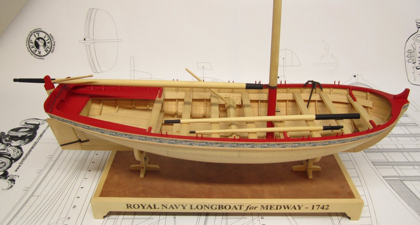
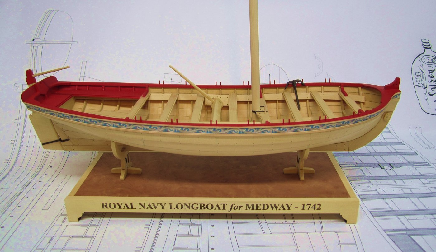
Today I finished the base and stand. I used yellow cedar around the base after applying a sheet of burled veneer which was darker. The hope was to make the boat stand out against the dark contrasting base. I added some lettering around the base so now I dont have to make a nameplate. Next time I will make the letters just a bit smaller but I am going to go ahead and use this one. Chuck

- 421 replies
-
- 24
-
-
- medway longboat
- Syren Ship Model Company
- (and 1 more)
-
Yes you can....it does make it easier. You can do it after you fair inboard but its harder. You need to brush it on and its tougher. Having said this...you will still want to add another coat at that time anyway. Chuck
-
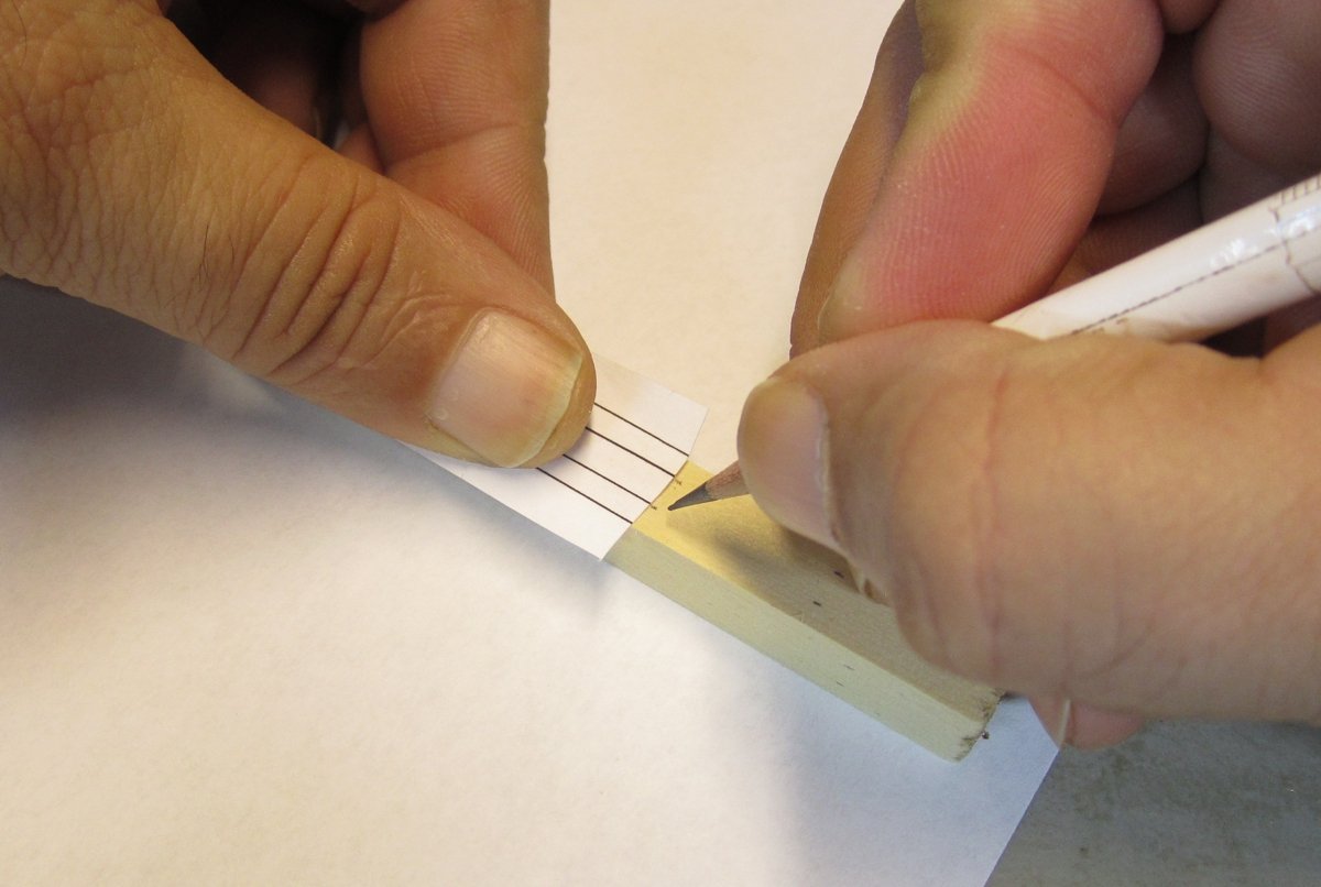
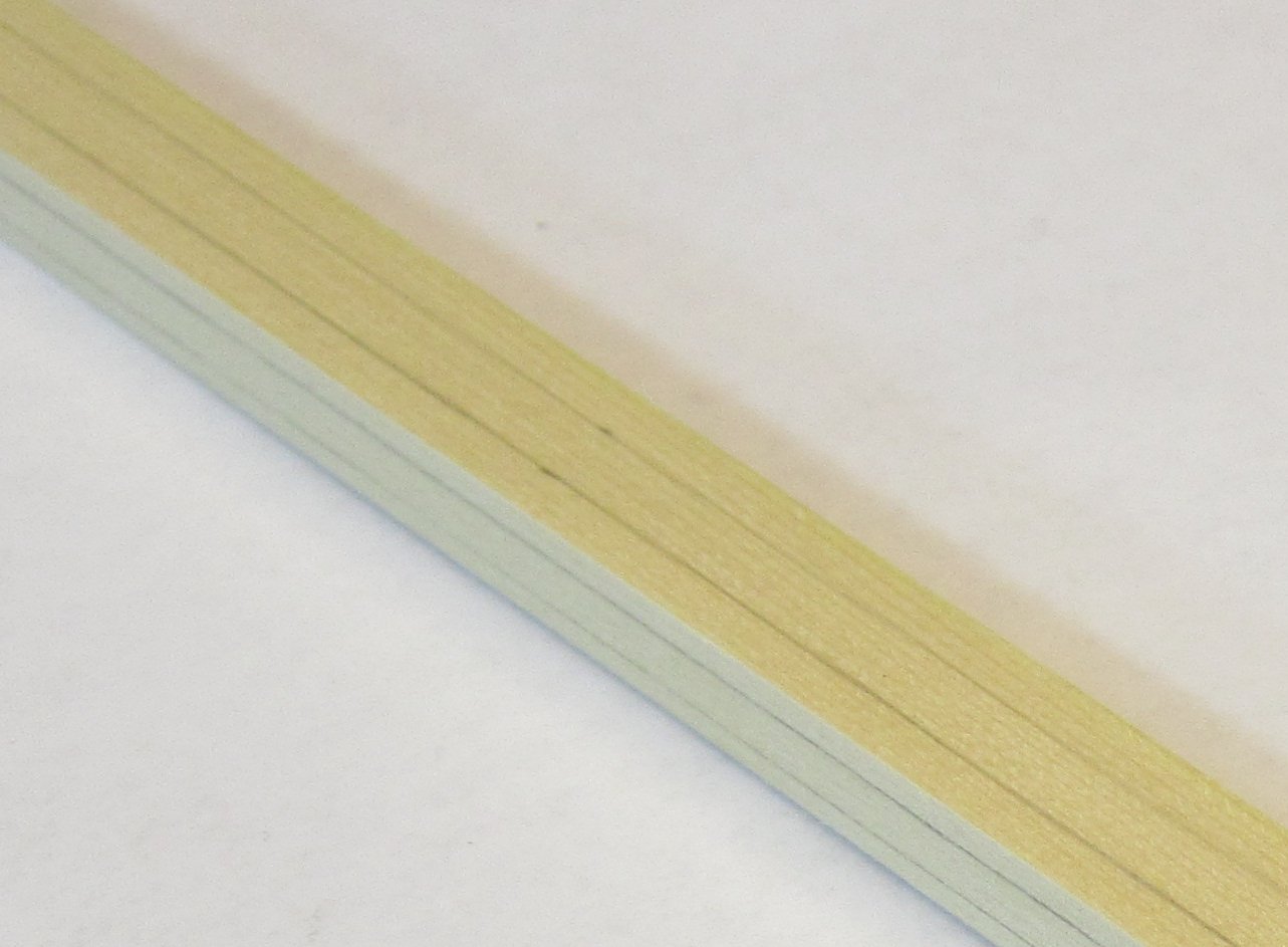
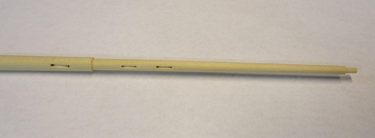
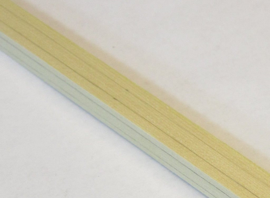
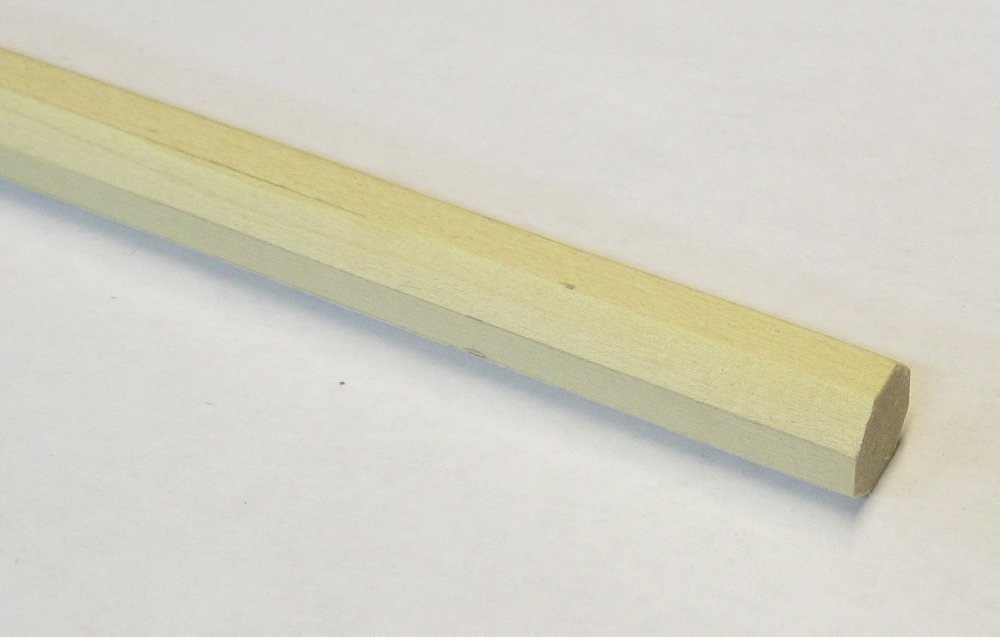
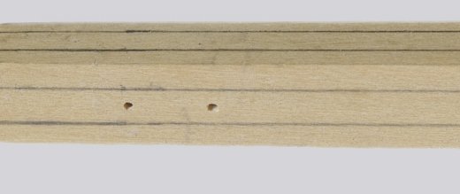
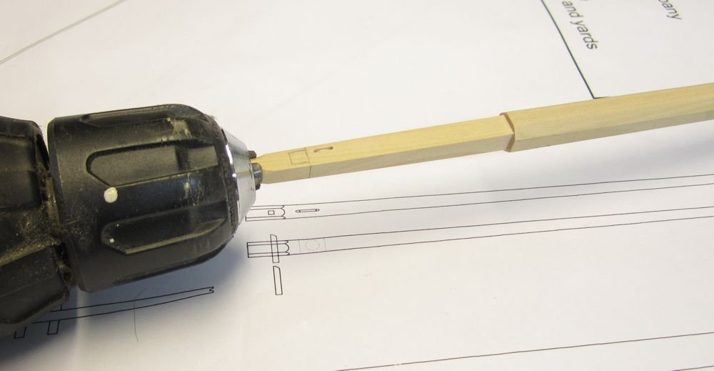
Started on the main mast. Because it is best to use the same wood as the rest of the project, a 3/8" x 3/8" square strip of cedar is being used. You could obviously replace this with a dowel of another wood already rounded off but the difference in wood texture and color would really stick out. Most of the mast and boom and gaff etc will NOT be painted. Its a good thing to try if you havent done so...rounding off a square strip like this. First I used the template provided to line out the strip with a 7/10/7 ratio. Just transfer the tick marks for the two center lines every four of five inches down each side of the mast. Using a 7/10/7 ratio will create a perfect octagon after the corners are shaved away. This is being done to make it easier to turn this in a lathe or chocked in a hand drill. The strip is 20" long and its much longer than you will need so there is plenty of meat on either side to chock this in your hand drill. Then connect you lines with a sharp pencil so you have a guide when slicing and planing off the four corners. I used a sharp #11 blade to shave and whittle off the corners almost down to the lines. It doesnt have to be perfect.....then I ran a sanding stick across the flats created. Then drill the holes that will be needed for the sheaves you will simulate on the mast later. There are three. It is easier to do this now while the strip is square. This is what my mast looks like after I shaved off the corners. Its ready for me to chock in my hand drill and taper it. This will take a while to do and be sure you use a mask because it makes a lot of dust. Here is a photo of how I do it in my hand drill.....this is from another project. I believe this is the lower mast for Cheerful. Or if you are lucky enough to own a lathe, that would be a good choice. I didnt worry about creating the small shoulder or stepped portion of the mast for the longboat. I will do that by hand once I create the general taper. In the end the lower part of the mast turned out slightly smaller than 3/8" which is just perfect. Then finally, I was able to finish up those sheaves so they looked good. To simulate the sheaves I used a #11 blade and some round needle files....you can use whatever you feel most comfortable with. Here is the final results. This was done after I created the stepped portion or "shoulder in the mast as you can see. This was just done by hand. The cedar worked very well for this operation and I was happy with the results. More to follow....


- 421 replies
-
- 24
-
-
-
- medway longboat
- Syren Ship Model Company
- (and 1 more)