HOLIDAY DONATION DRIVE - SUPPORT MSW - DO YOUR PART TO KEEP THIS GREAT FORUM GOING! (Only 13 donations so far - C'mon guys!)
×


Chuck
-
Posts
9,660 -
Joined
-
Last visited
Content Type
Profiles
Forums
Gallery
Events
Everything posted by Chuck
-
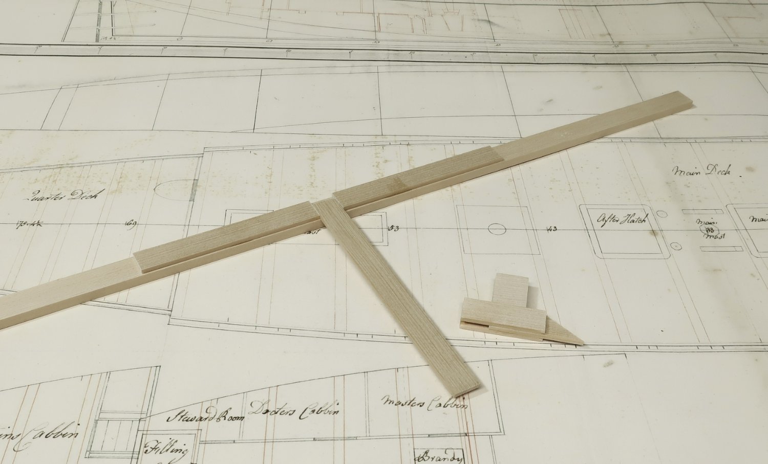
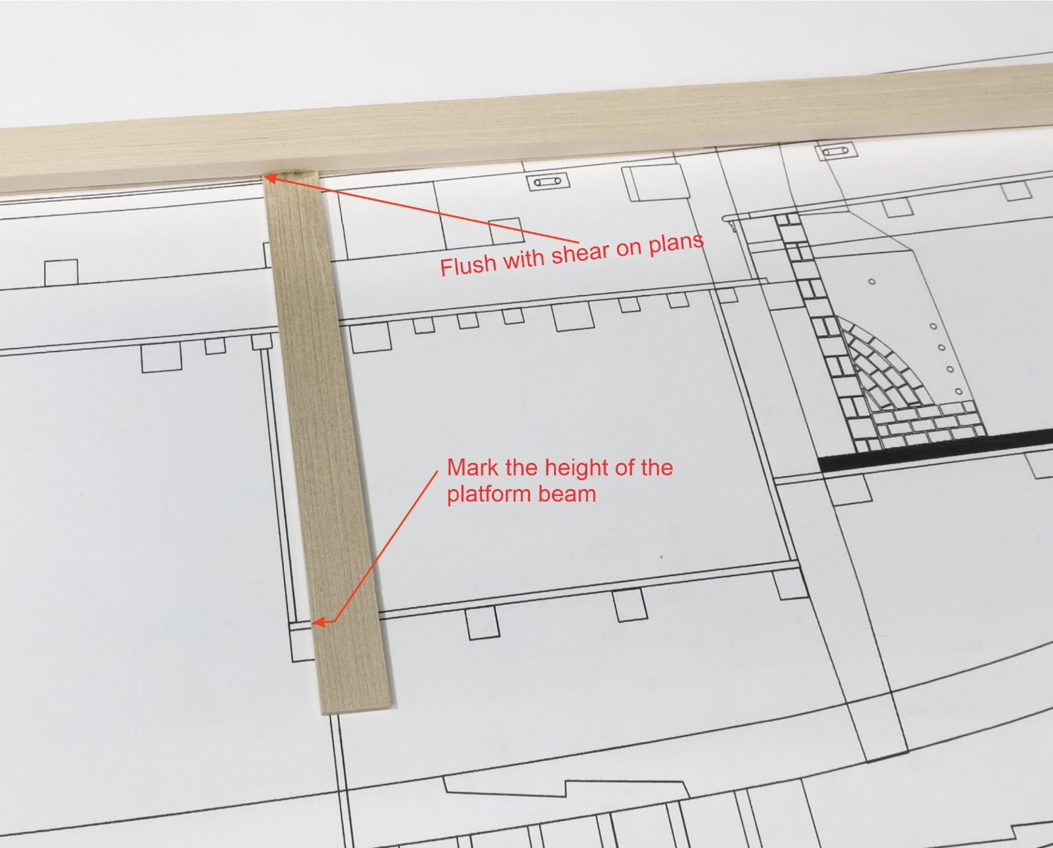
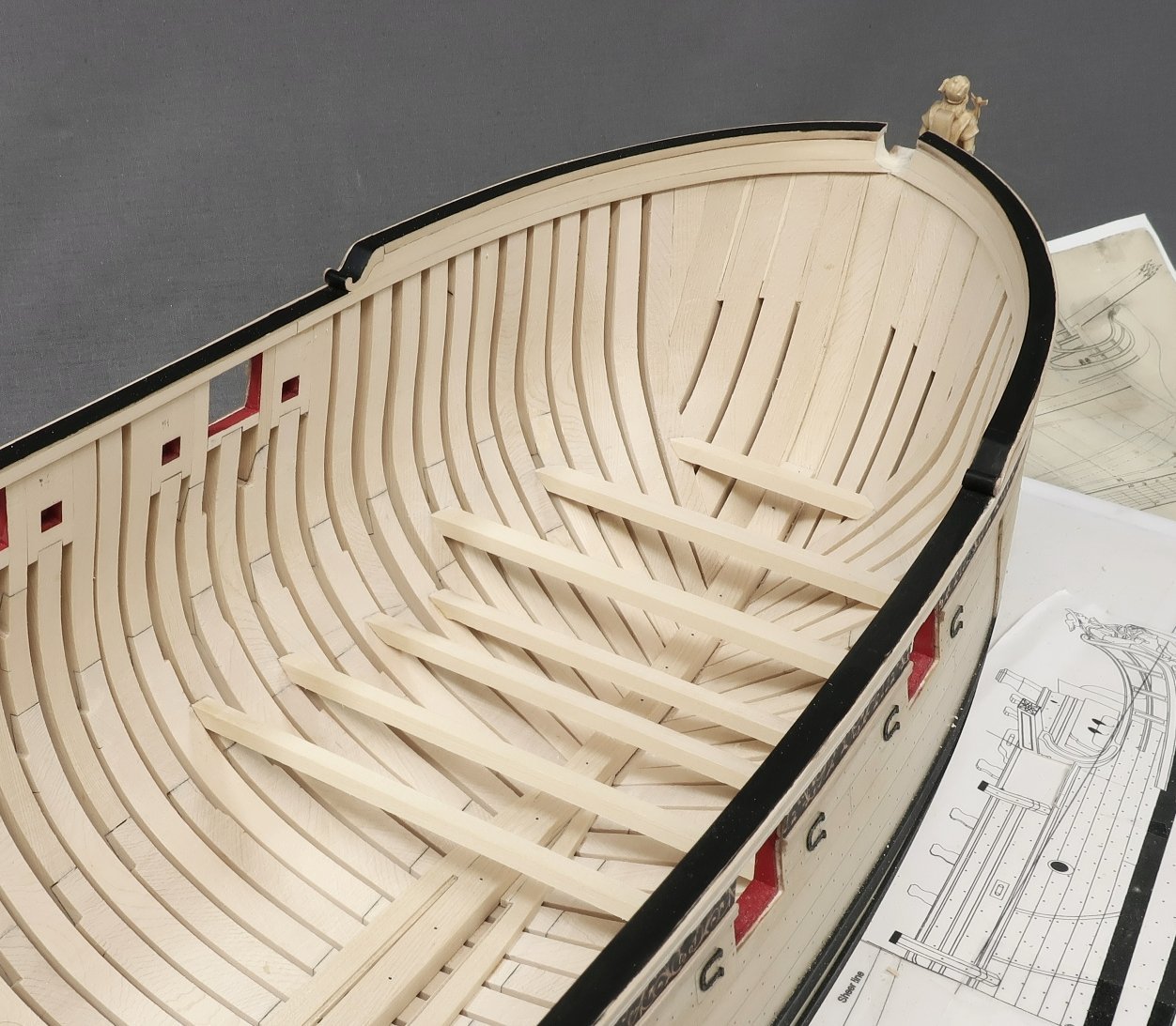
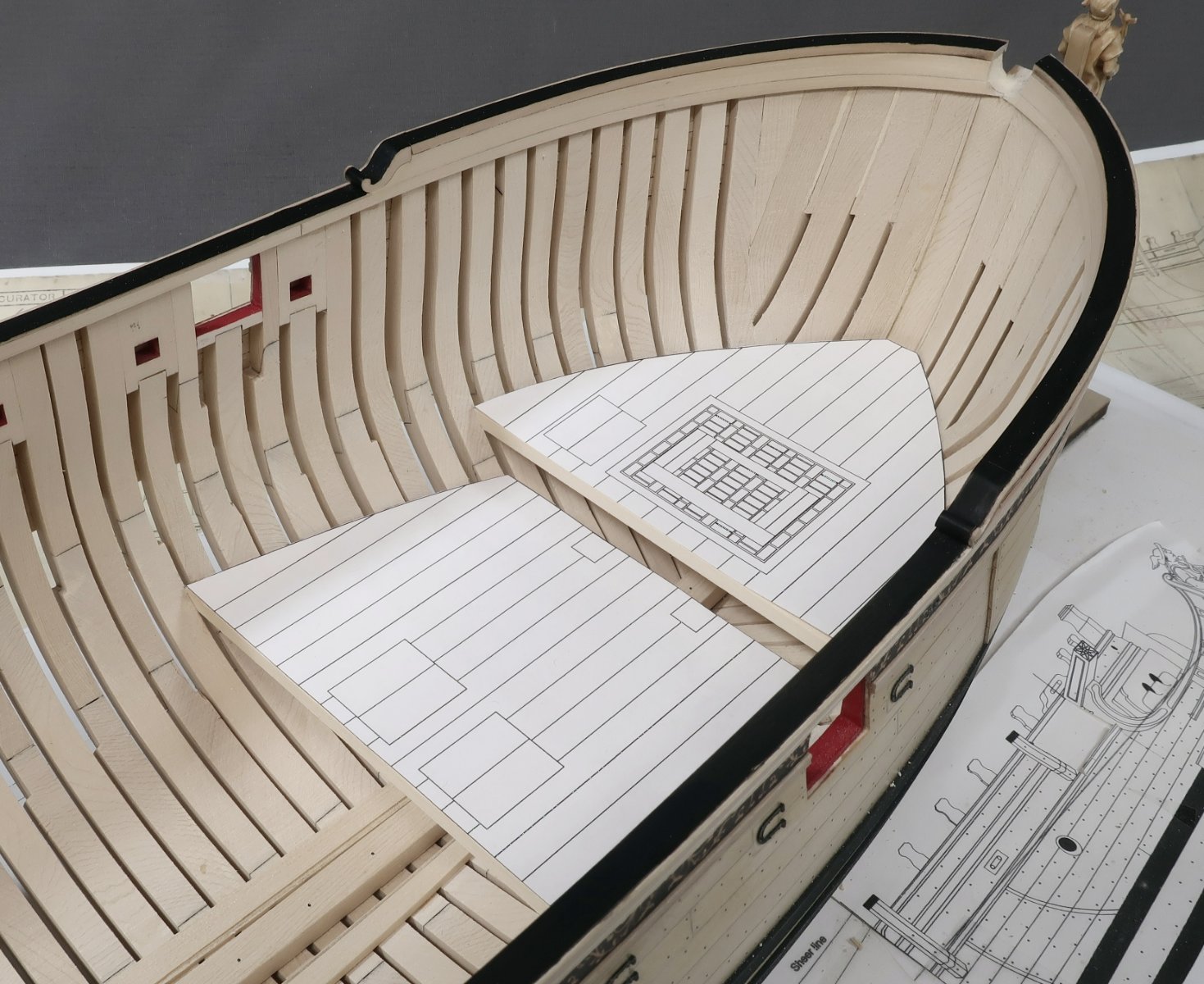
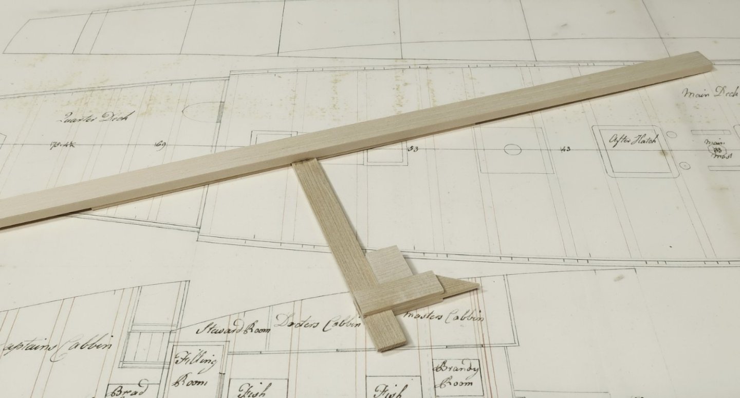
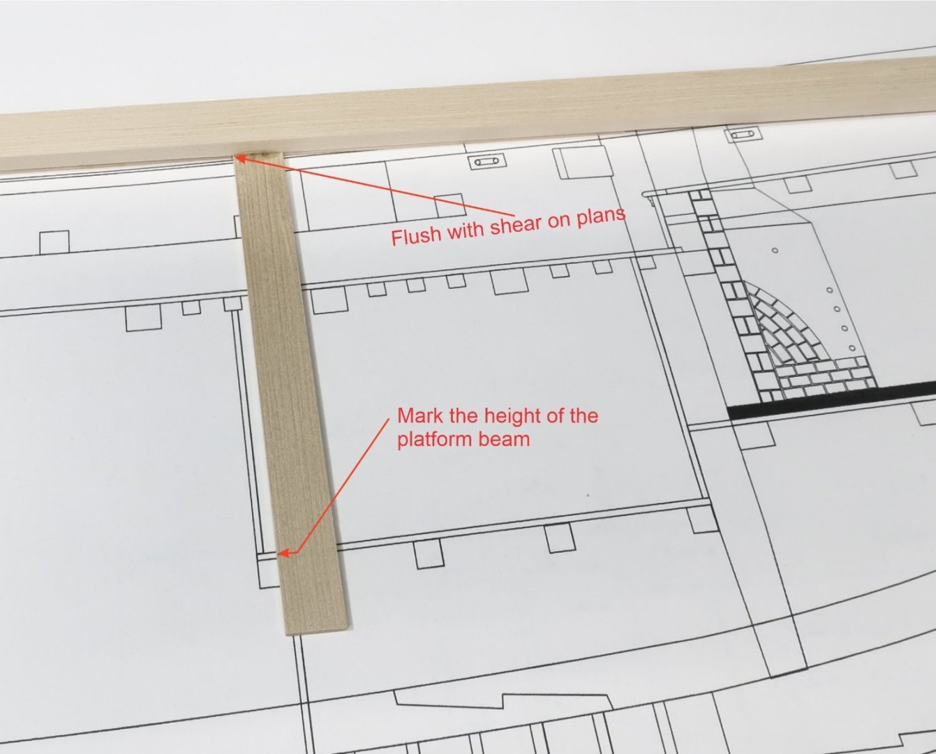
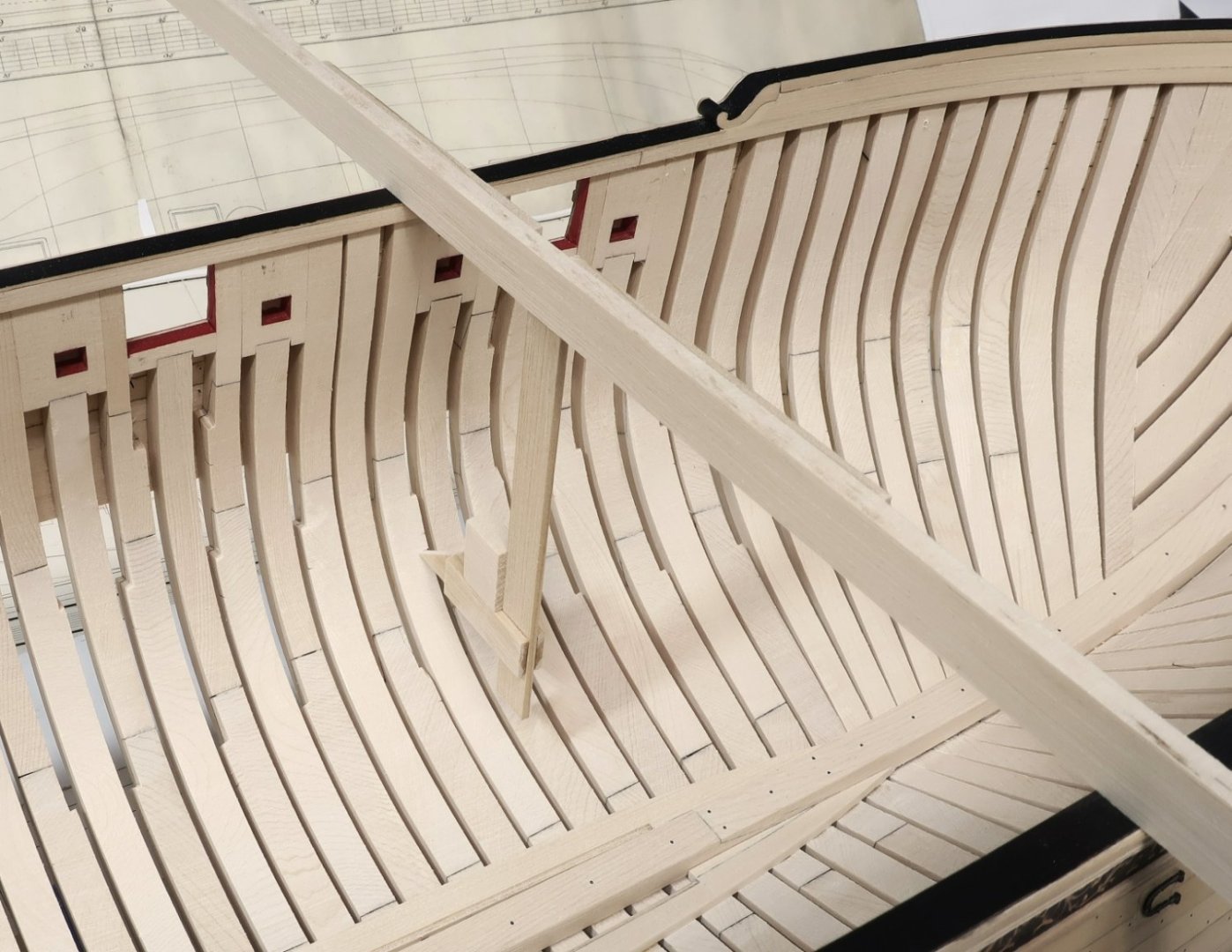
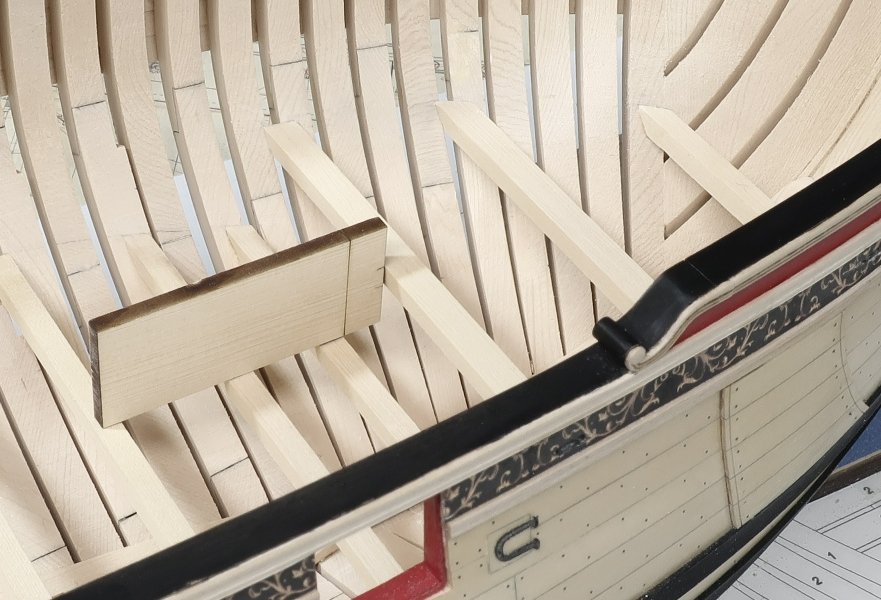
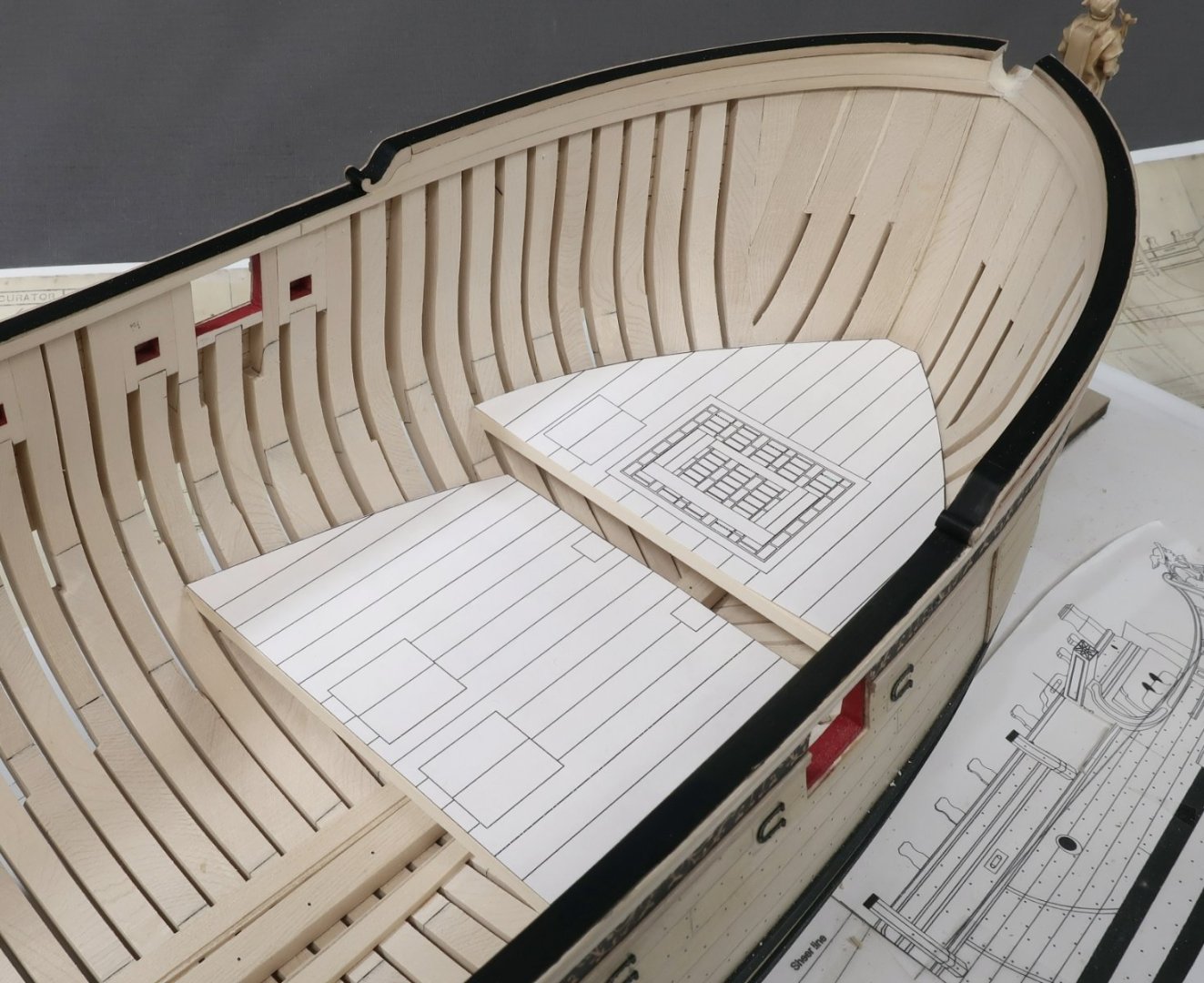
 Before I can begin placing the beams for the lower platforms, I must make a height gauge first. There are many ways to do this and a system will be very important to have moving forward on this project. Greg describes one method in his books on Speedwell. I have decided to go another way. I prefer to make a depth gauge of sorts. Here is a photo...you folks can of course select any method you prefer. I am fond of this one and such a gauge can be made with readily available scrap strips...Note how the pointer is a separate it to be slipped onto the lower shaft. It is basically a very large T-square. I used 3/32" thick strips but they are fairly wide so they wont bend or flex. The center of the "T" is thinner at about 1/16" thick. The pointer is meant to be slid onto the center shaft of the "T". Everything is squared up and at perfect right angles. Nice and neat. Basically take the measurements from the plans to find the depth of any beams etc. Like the forward platform beams. The underside of the "T" is set flush with the sheer on the plan. Then I mark the top of the platform beam on the center shaft...without the pointer on it. Just a pencil tick mark. Then the pionter is added to the shaft and lined up with the tick mark. The pointer must fit nice and snug so it doesnt shift around. Its a very tight fit on purpose. Then the depth gauge can be brought to the model as shown. Repeat on both sides for each beam end. I am marking the height for the tops of the beams. Find where that beam should be and mark its height on the model. Repeat this process for every lower platform beam end. Then connect the marks to find the proper height for the platform. Basically repeat this on both sides. Hope that makes sense. I am basically trusting that my sheer on the model is correct and even on both sides. I am confident... But if your sheer is off you have bigger problems anyway. No matter what method you choose there will be issues. This is just one method that can be used. I did this for all the lower platform beams which are 3/16" x 3/16" cedar. That is except for the most forward platform which has 1/4" x 3/16 beams just under the stove. Check you plans carefully. The beams have no roundup and are just cut from strip stock. They are carefully measured and shaped to fit snug. Placement is important here. In fact the placement of the first 1/4" x 3/16 beam of the forward-most platform is very important. It is exactly 5/16" away from the beam aft of it on the lowest platform. So a small jig was laser cut to help find its location. This will be provided. It sits on the lower platform beams which went in first. It has laser etched marks to help you place that first beam in position correctly at the right height and the right distance from the lower platform beam. Once all seven of the forward platform beams were in place I tested my placement with the a cutout of the plans. Everything is level and the plans fits pretty darned good. Next up is to add the a bulkhead and some additional framing on these platforms before I plank them. Hope this makes sense... Chuck
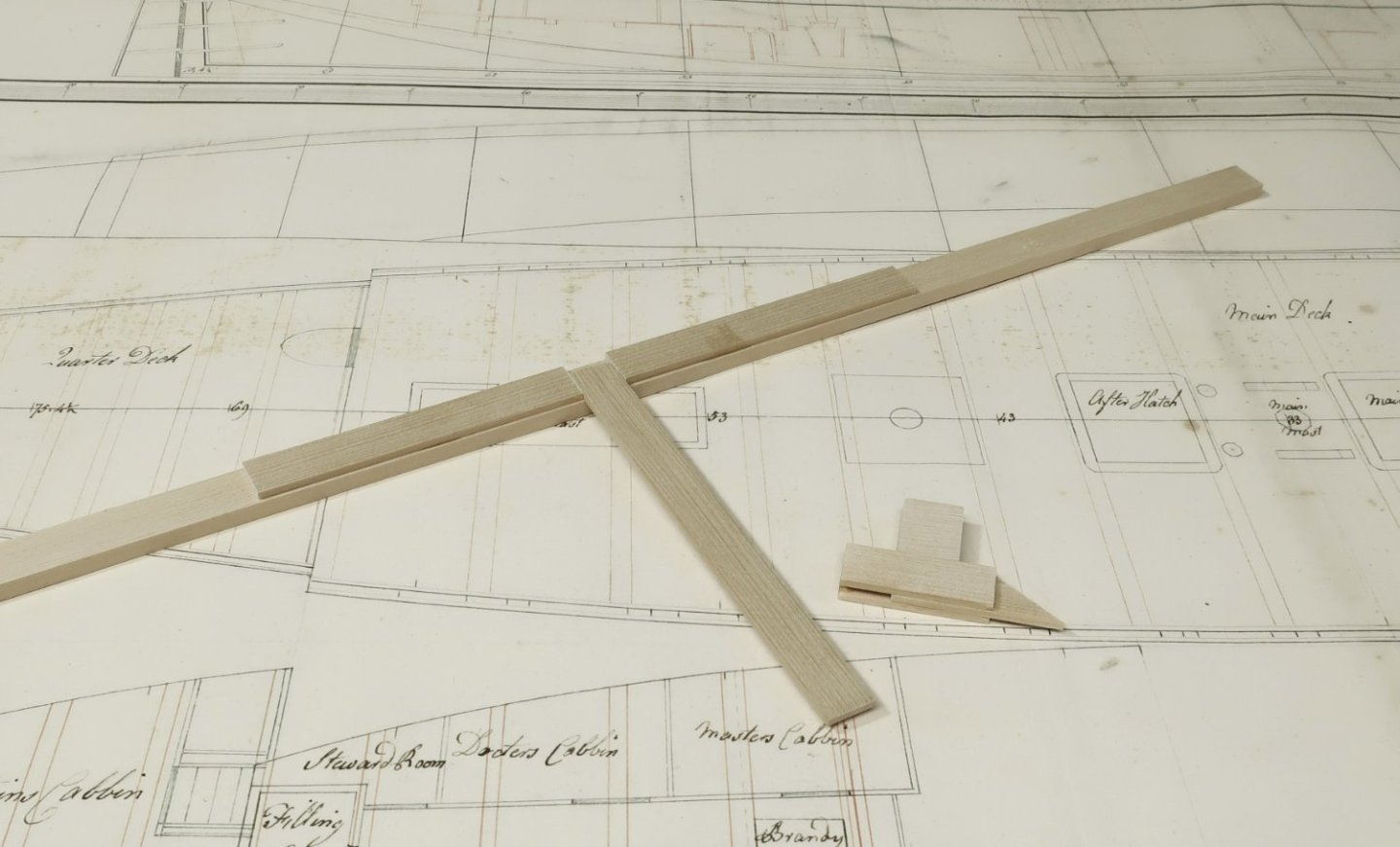

-
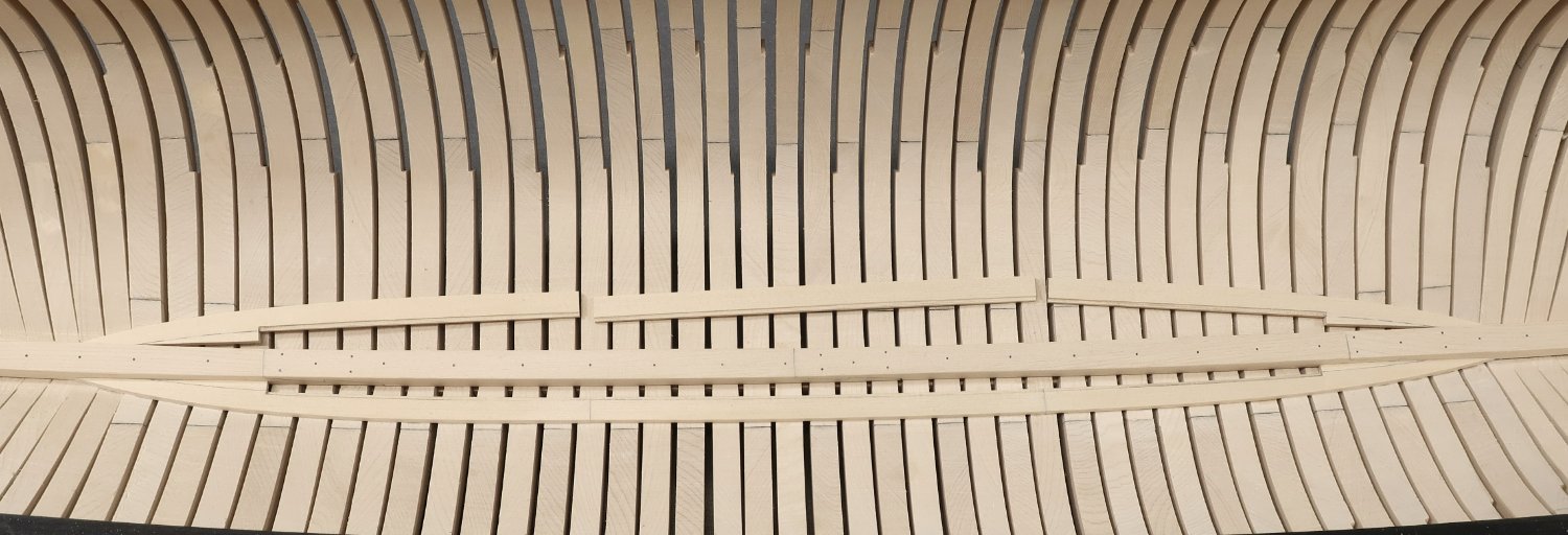
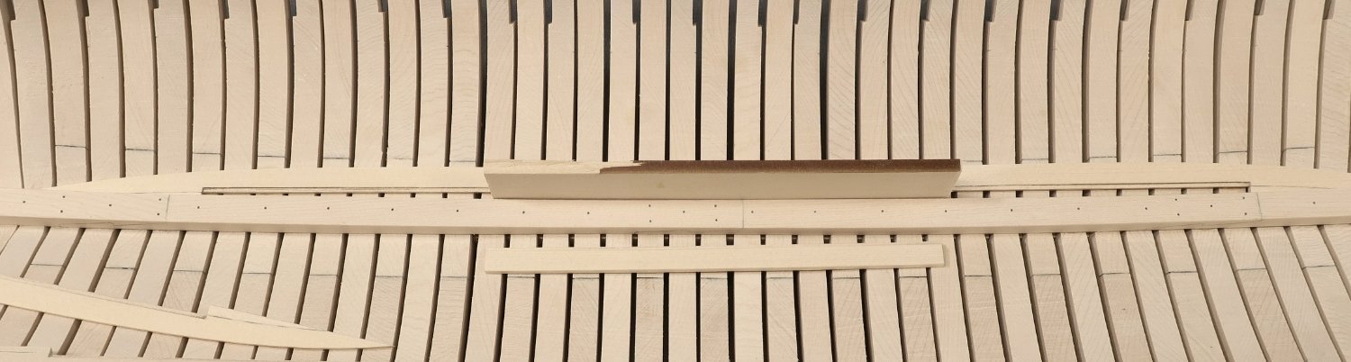
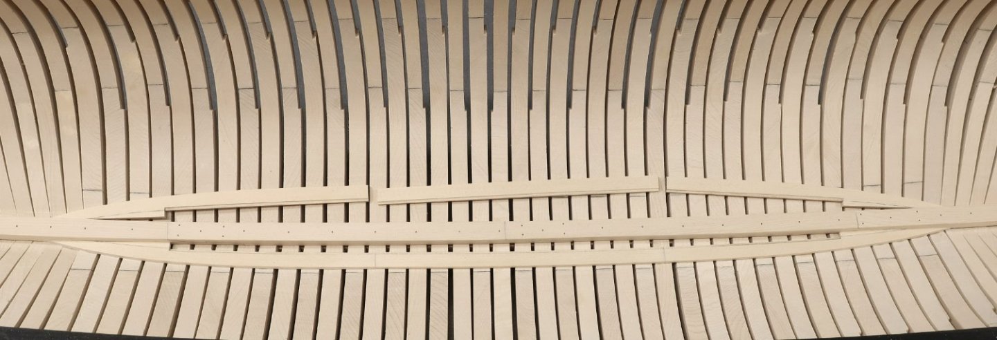
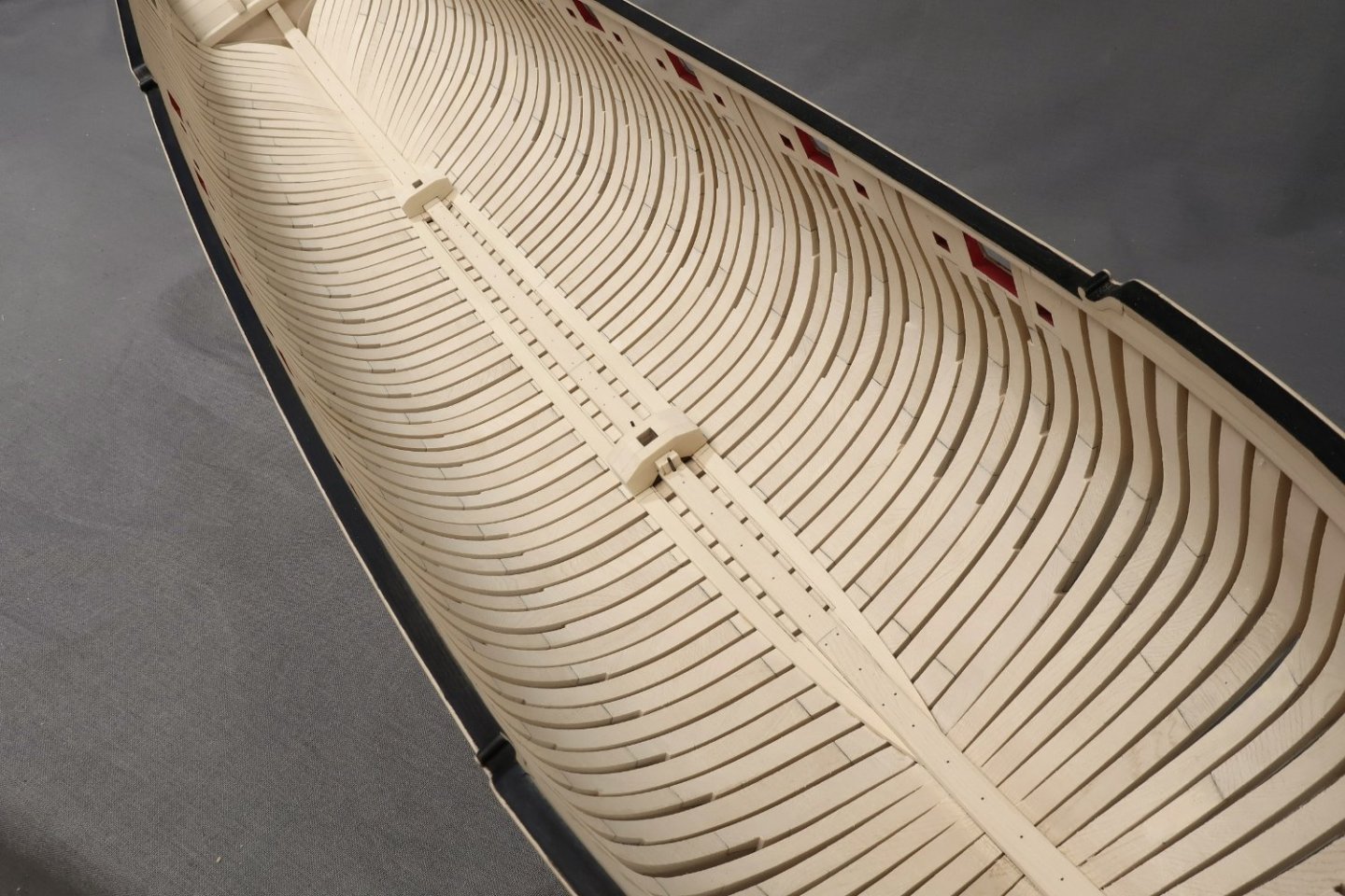
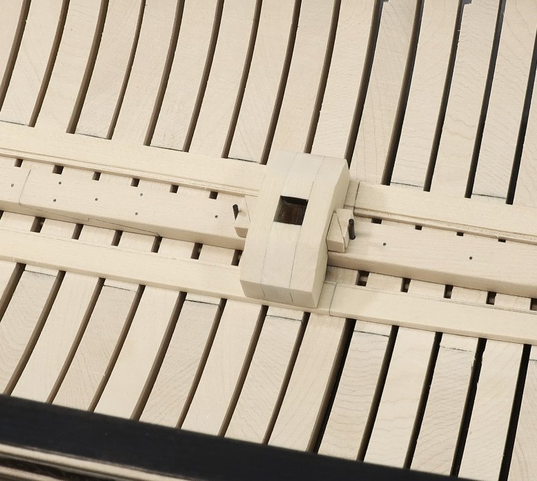
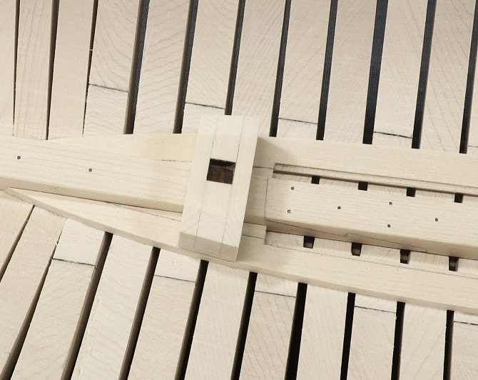
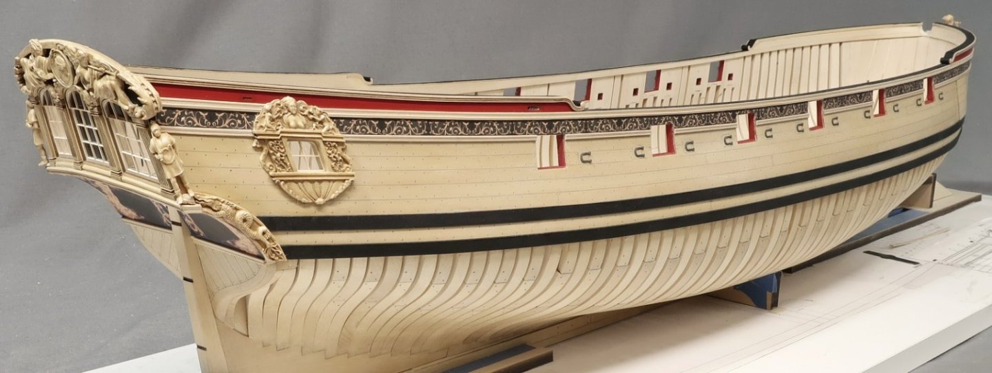
Work has started on the interior. Not much in this initial step but it was good to get started again. First up was to add the limber strakes. In the photo below you can see the completed limber strake below the keel. This was made up up three lengths. Above the keel you can see the 3 lengths not yet glued into position. They are laser cut for you and are 3/32" thick. There is a laser etched rabbet which runs along the inside edge. Each of the three lengths were first sanded free of laser char. This included carefully sanding the rabbet more or less. But it doesnt have to be completely clean. This will be completely covered up in some areas with the lower platforms anyway. But do your best. You might also notice the little ….long, triangular pieces called Limber Fillers for lack of a better term. They were glued to each limber strake ahead of time. They are at the extreme ends fore and aft. Dry fit all three lengths in position first. This is important. Make sure they are lined up with the correct frames. You can take their positions on each end from the plans. The center limber strake was added first. The ends are 5/32" away from the keelson. So it was just a matter of taking a scrap piece of wood 5/32" thick to use as a spacer when gluing it in position. This is shown below. Once again...make sure you position it in the correct spot and use the plans to find which hull frames this should line up with. Its good practice because so many items moving forward need to placed in the correct spot...the hull frames are a great reference to start with. Once the center segment was glued in place the two end sections followed. Make them the same port and starboard of course. But you may also wish to pre-bend these before you glue them in position. Especially at the bow and stern sections. There is a little bit of twist to these and it is always better to not force them. It is so much easier to pre bend and twist so no forcing of the limber strakes will be needed to get them to sit flush against the frames. With the limber strakes completed, the mast steps can be assembled and installed. I would also note that I didn't bother treenailing the limber strakes because it will just not be seen. But you can do that if you feel compelled. The mast steps are laser cut in three layers to make life easier. Glue up the three layers first and remove the laser char. Once they are nice and clean, check their fir over the keelson. You should get a nice tight fit and the sides should fit snug down on top of the limber strakes. Note how the outside edges of the mast steps follow the shape of the limber strakes. You should sand them as shown in the photos and plans. The main mast step is shown below. You can clearly see the three layers. Dont worry about the char in the mortice for the mast. Leave that as is. The main mast step also has little wedges fore and aft as you can see. These are laser cut for you. They were glued into the correct position on top of the keelson. This is important!!! place the mast step in the correct place or your masts placement will certainly become problematic. A small length of 3/64 brass rod was used as the pin to "lock in" the little wedges after I glued them all in position. A look at the mizzen mast step...no issues here other than the fact that the sides of the mast step have more shaping here. They also follow the outside edge of the limber strakes. I have not applied any finish inboard at all up to this point. I actually might not apply any finish. I will wait to see how things develop first. An overall view of the mast steps and limber strakes. I will not be adding the limber boards, choosing instead to follow Greg's construction and to simplify the building process. "Less is more" when you leave the framing visible below the wales. You wont want to see much stuff between the frames when you looking at the outside of the hull. It could start to look sloppy with too much interior details and glue showing between the frames. So I will follow the style as outlined in the Seawatch books for the most part. Next up the forward lower platforms!!!

-
Looking great Mike....Just remember that the lower edge of counter is flush with the square tuck after planking. Chuck
-
Moving posts
Chuck replied to petehay's topic in Using the MSW forum - **NO MODELING CONTENT IN THIS SUB-FORUM**
No but any moderator can. What do you want to move. chuck -
real ship photo thread?
Chuck replied to hamilton's topic in Using the MSW forum - **NO MODELING CONTENT IN THIS SUB-FORUM**
Same situation as you might guess!!! After we found hundreds and hundreds more all posted by the same member mostly. He had found another site that a photographer owned and who had hundreds of pics all copyrighted. The MSW member didnt care and just kept posting after numerous warnings from our staff. We finally had to let that guy go…no reasoning with some folks. rather than spend a week sifting through pages of posts and deleting just the copyright images it was just easier to delete the entire topic. -
real ship photo thread?
Chuck replied to hamilton's topic in Using the MSW forum - **NO MODELING CONTENT IN THIS SUB-FORUM**
We actually had one but folks didnt take copyright seriously. They just copy pasted from all over the web. And we got caught. I guy whose pics were lifted and posted here caused us some serious heartache. He wanted $$$….and threatened with lawyers. Of course we removed them the moment we were notified but that didnt stop the guy. Finally I told him to go after the member who posted them… That we werent responsible. So that was that. But it was dicey for a while. -
Glad to see you back at it.
-
Motored Syren Rope Rocket (Modification)
Chuck replied to modeller_masa's topic in Modeling tools and Workshop Equipment
I dont see why not. It will be interesting to see how it works in actuality. -
Lovely start!!!
-
Looking really good…well done.
-
I am still waiting on wood to start cutting chapter two parts. Hopefully soon.
-
That is some fine rope...well done. Its easy once you get into a routine. I have about 50 packages of rope to make today as well...about 1200 feet....I better get to it!!!
-
You could be twisting too much.....all four strands together. You probably need more initial twisting of individual strands. I would suggest a three strand rope for that size as well. No need to water poly rope....it wont do anything. That is just for cotton or natural fibers.
-
Really beautiful model!! It may have taken a while but the results speak volumes. Well done.
-
That is such a lovely model indeed. Great to see it all finished up...and the rope looks great too!!! I am looking forward to your next adventure. Chuck
-
Happy New Year everyone!!! I shall be back working on the Speedwell prototype really soon. Hopefully this week in fact. But I wanted to update you guys on the release of the first installments for sale. I had hoped to have launched the first chapters of parts by mid January. But because of the Movie and my wood supply with Joes shop being flooded, I havent had enough wood or time to complete all the laser work yet. I actually have the first ten sets of chapter one parts ready to go. I could place them on my site right now for sale which include the plans for the hull framing. Two sheets. I have also written and posted the first chapter of the monograph on the online store. But I had hoped to have the first two chapters ready and laser cut before I started offering them. This way you guys can order both chapters at once which complete all the hull framing and can save on shipping costs. That is still my plan and hopefully I can get the needed wood to start cutting chapter two parts within a week or so. I dont anticipate too much of a delay. In the meantime, those of you who have decided to build my kit of Speedwell can download the first chapter and read it over. You can also buy whatever wood and tools you might need ahead of time as well. For example the board for the buildboard and maybe some machinist squares etc. I will announce when the first two chapters of parts are listed for sale as son as finish some chapter two parts. Maybe I will only wait to have five finished of the original ten sets as I know many of you have been emailing me that you are eager to get started. More to follow soon.
-
Looking good. Well done.
-
HM Cutter Cheerful 1806 by JpR62 - 1:48 scale
Chuck replied to JpR62's topic in - Build logs for subjects built 1801 - 1850
That is looking fantastic. Happy to see you making progress on the Cheerful. Have a great Holiday and New Year!!! -
That is looking wonderful.
-
That is looking excellent!!! Have a great holiday and new year!!!
-
Laser cutting services?
Chuck replied to Jsk's topic in CAD and 3D Modelling/Drafting Plans with Software
Its crazy expensive but yes. For example, National balsa....Ponoko....Hammerspace...... offers laser cutting services. The issue is the material you want to use. Most only have and offer the basics (basswood, plywood....maybe cherry and and some others) and in a very limited range of thicknesses. Prepare to pay around $1.50 - $2.50 per minute of laser time plus materials and up front costs. Considering that one sheet of parts could take 12 to 18 minutes to cut depending on the size and complexity. You can also search laser cutting services on Etsy and you will find a large number of people. I have no idea how good they are, but it is crazy expensive for one-off runs. Chuck -
HM Cutter Cheerful 1806 by Erik W - 1:48 scale
Chuck replied to Erik W's topic in - Build logs for subjects built 1801 - 1850
Lovely!! -
Really nice progress. Nice job on that planking.