Chuck
-
Posts
9,703 -
Joined
-
Last visited
Content Type
Profiles
Forums
Gallery
Events
Everything posted by Chuck
-
 That is such a lovely model indeed. Great to see it all finished up...and the rope looks great too!!! I am looking forward to your next adventure. Chuck
 -
Happy New Year everyone!!! I shall be back working on the Speedwell prototype really soon. Hopefully this week in fact. But I wanted to update you guys on the release of the first installments for sale. I had hoped to have launched the first chapters of parts by mid January. But because of the Movie and my wood supply with Joes shop being flooded, I havent had enough wood or time to complete all the laser work yet. I actually have the first ten sets of chapter one parts ready to go. I could place them on my site right now for sale which include the plans for the hull framing. Two sheets. I have also written and posted the first chapter of the monograph on the online store. But I had hoped to have the first two chapters ready and laser cut before I started offering them. This way you guys can order both chapters at once which complete all the hull framing and can save on shipping costs. That is still my plan and hopefully I can get the needed wood to start cutting chapter two parts within a week or so. I dont anticipate too much of a delay. In the meantime, those of you who have decided to build my kit of Speedwell can download the first chapter and read it over. You can also buy whatever wood and tools you might need ahead of time as well. For example the board for the buildboard and maybe some machinist squares etc. I will announce when the first two chapters of parts are listed for sale as son as finish some chapter two parts. Maybe I will only wait to have five finished of the original ten sets as I know many of you have been emailing me that you are eager to get started. More to follow soon.
-
Looking good. Well done.
-
HM Cutter Cheerful 1806 by JpR62 - 1:48 scale
Chuck replied to JpR62's topic in - Build logs for subjects built 1801 - 1850
That is looking fantastic. Happy to see you making progress on the Cheerful. Have a great Holiday and New Year!!! -
That is looking wonderful.
-
That is looking excellent!!! Have a great holiday and new year!!!
-
Laser cutting services?
Chuck replied to Jsk's topic in CAD and 3D Modelling/Drafting Plans with Software
Its crazy expensive but yes. For example, National balsa....Ponoko....Hammerspace...... offers laser cutting services. The issue is the material you want to use. Most only have and offer the basics (basswood, plywood....maybe cherry and and some others) and in a very limited range of thicknesses. Prepare to pay around $1.50 - $2.50 per minute of laser time plus materials and up front costs. Considering that one sheet of parts could take 12 to 18 minutes to cut depending on the size and complexity. You can also search laser cutting services on Etsy and you will find a large number of people. I have no idea how good they are, but it is crazy expensive for one-off runs. Chuck -
HM Cutter Cheerful 1806 by Erik W - 1:48 scale
Chuck replied to Erik W's topic in - Build logs for subjects built 1801 - 1850
Lovely!! -
Really nice progress. Nice job on that planking.
-
They look great Frank...Cant wait to see an overall shot of your hull from the stern quarter when you get it all done.
-
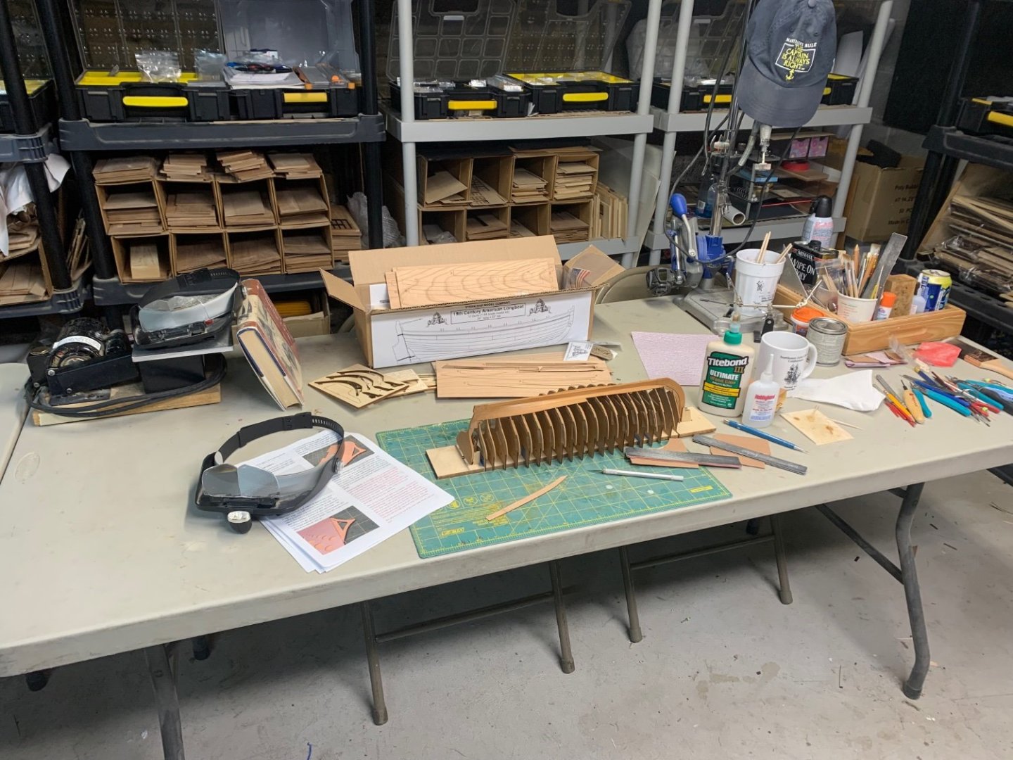
Stretcher boards. Long boards sit in those "V"s which the rower then pushes against with their feet.
-
She looks fantastic. I hope you enjoyed the project. Your model looks wonderful.
- 137 replies
-
- 2
-

-
- winchelsea
- Syren Ship Model Company
- (and 1 more)
-
Cheerful build query
Chuck replied to CaptnBirdseye's topic in Building, Framing, Planking and plating a ships hull and deck
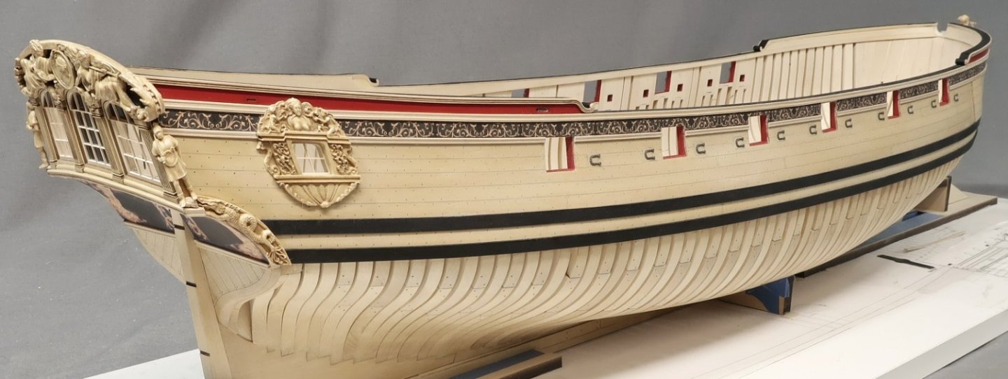
The cutter Cheerful as well as many small cutters from this era did NOT have a false keel. Please disregard that info so as to not get confused with your dilema. But as to your issue at hand and considering the terminology... you probably just need to sand back the aft side of the stem assembly. Basically sand where it initially touches the BH former rabbet strip. This will easily close up the gap above it and below where it initially touches. It doesnt even have to be completely closed up as long as you get a decent glue joint for most of the length of the rabbet strip along the stem assembly. Remember to have fun with the project. I also encourage you to start a build log. I couldnt find one but it would be so much easier for the folks who have built the Cheerful to help you as you proceed. Chuck -
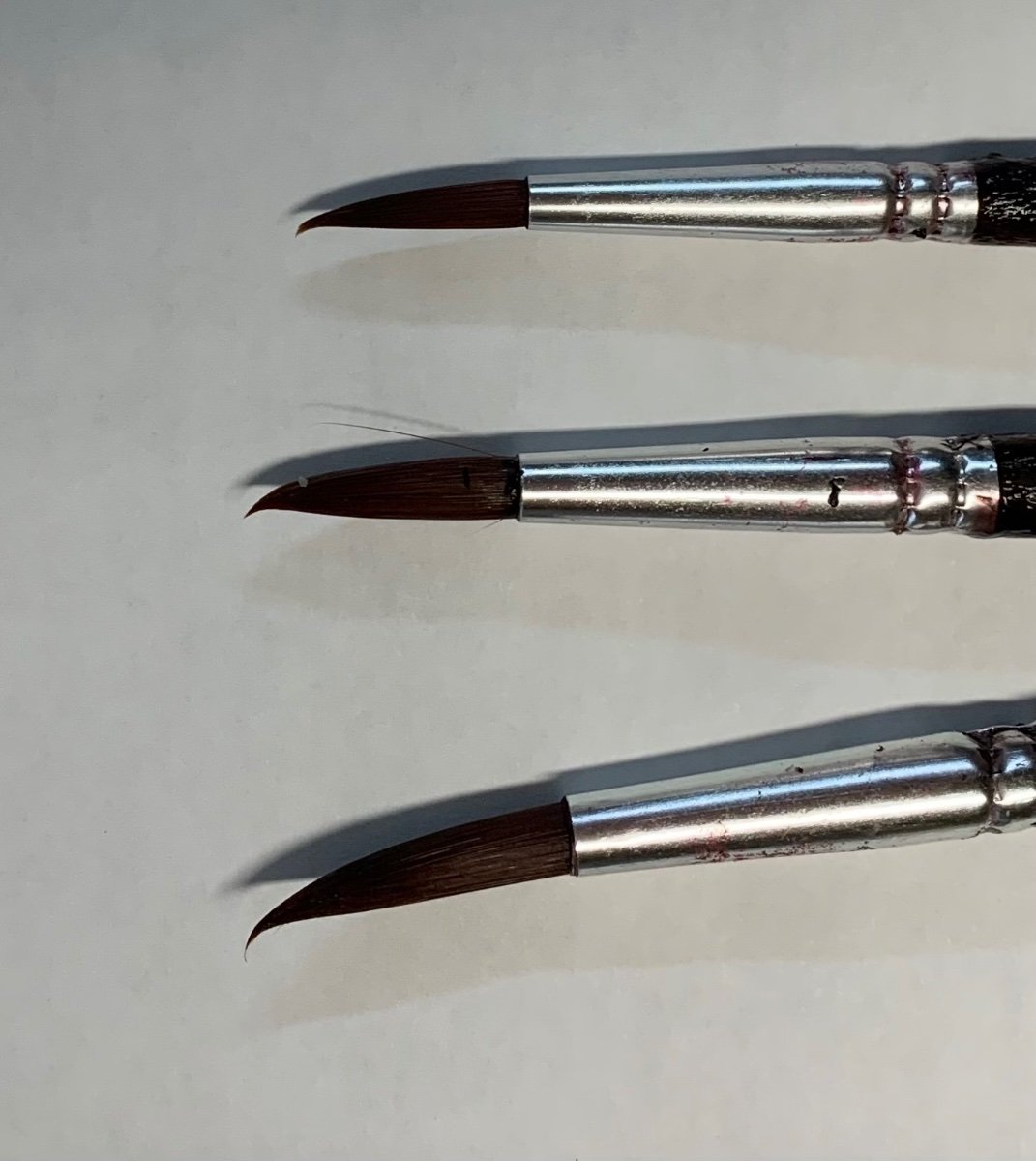
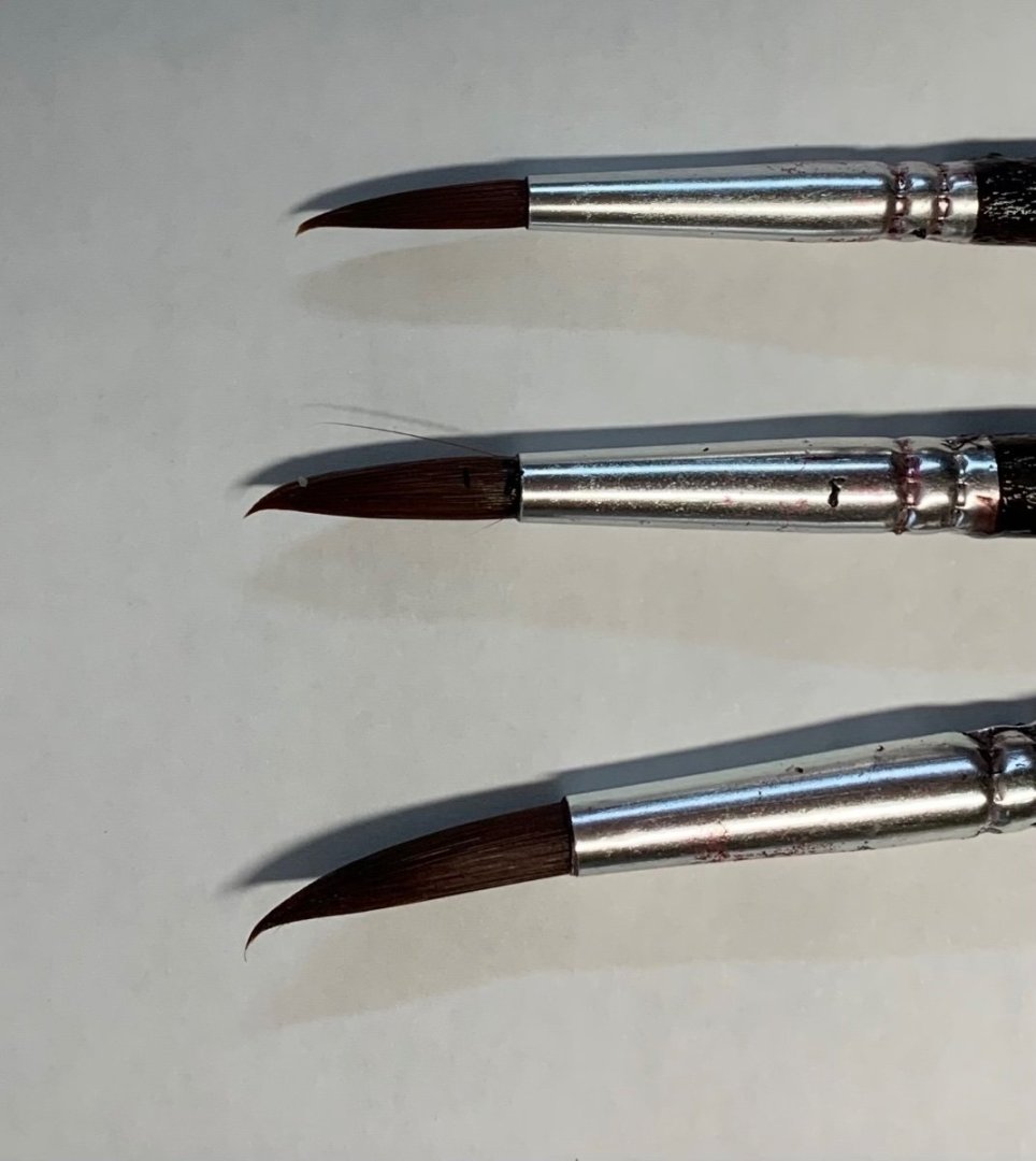
Well, simply put...there is no reason to wait in order to paint. Its best to have painted those areas before they became hard to reach. Usually that is best when planning. It is much easier to do a bit of touch up later and dust can be cleaned away without hurting the painted surfaces. Having said that...I do keep several brushes of good quality in a cup of water all the time. I do this to actually force the tips of the brush to bend and keep the bend. This allows me to apply a bit of paint to the tip of the brush which can be used to get in some tight spaces. But not that tight. It is always best to paint parts before they become inaccessible. I have other brushes with even more of a bend. These are three I had readily at hand.
- 18 replies
-
- 13
-
-
That is my hope....if I can do my small part. I do get vetoed a lot. The movie isnt about ship modeling but the guy just happened to be a an experienced intermediate kit builder. Many scenes will take place in the garage workshop. I have a gigantic pile of old journals and seaways ships in scale mags to leave scattered throughout the house....LOL. But they keep taking them away. Its pretty friendly though. I mentioned that my admiral doesnt like my ship model stuff all around the house either. Then puzzled.... they asked me...."Your Admiral?" I explained that many ship modelers refer to their significant others fondly or even not so fondly as the admiral. They all laughed and have decided to write that into the script...LOL. They want the guy to be a real ship modeler. One scene the wife enters and breaks a model and yells at the actor to clean up all the sawdust and mess. Sawdust I happily swept up from my shop floor the night before. Chuck
-
I was busy today and missed this thread but I will add that early on our members were actually scammed on MSW. This happened exactly how one would expect. Someone pretended to have lost a relative (father) and had their stuff from 30 years of ship modeling to sell. He listed them all and took PayPal payments and nobody received anything. Thousands of dollars worth of tools and kits and books. It was a complete and total scam. By the time we suspected and found out...the email was disconnected along with the paypal address. Photos of the stuff were pasted from the web etc. This is what prompted our rule about 25 posts (originally 50) and for folks who sell stuff to be vetted or be members in good standing. But yes it is always buyer beware. It is too easy to get scammed these days. It usually happens around the holidays too!! So please...damned if we do and damned if we dont. I would rather have folks here be mad at us for protecting them rather than screaming at us after they were scammed here out of not so insignificant $$$....It is for our community protection. We have always had exceptions. Most folks contact either me or Kurt and we make it so they can create a topic here. We must have missed this one and they never contacted us directly. But usually we know these guys who passed away and even their relatives. So we vet them ahead of time and endorse them when they finally make a post about the stuff. If you dont see that, please be aware its all your risk. But if you dont see such an endorsement...please bring these topics and posts to our attention so we can do our due diligence and make sure it is legit.
- 11 replies
-
- 19
-
-

-
No winnie…only small boats. Lots of half built models from my shop just placed all over in his fake workshop. But once I have it all set up I hope to have actual pics…maybe with some of actors if they would allow it. But there are so many freaken rules.
-
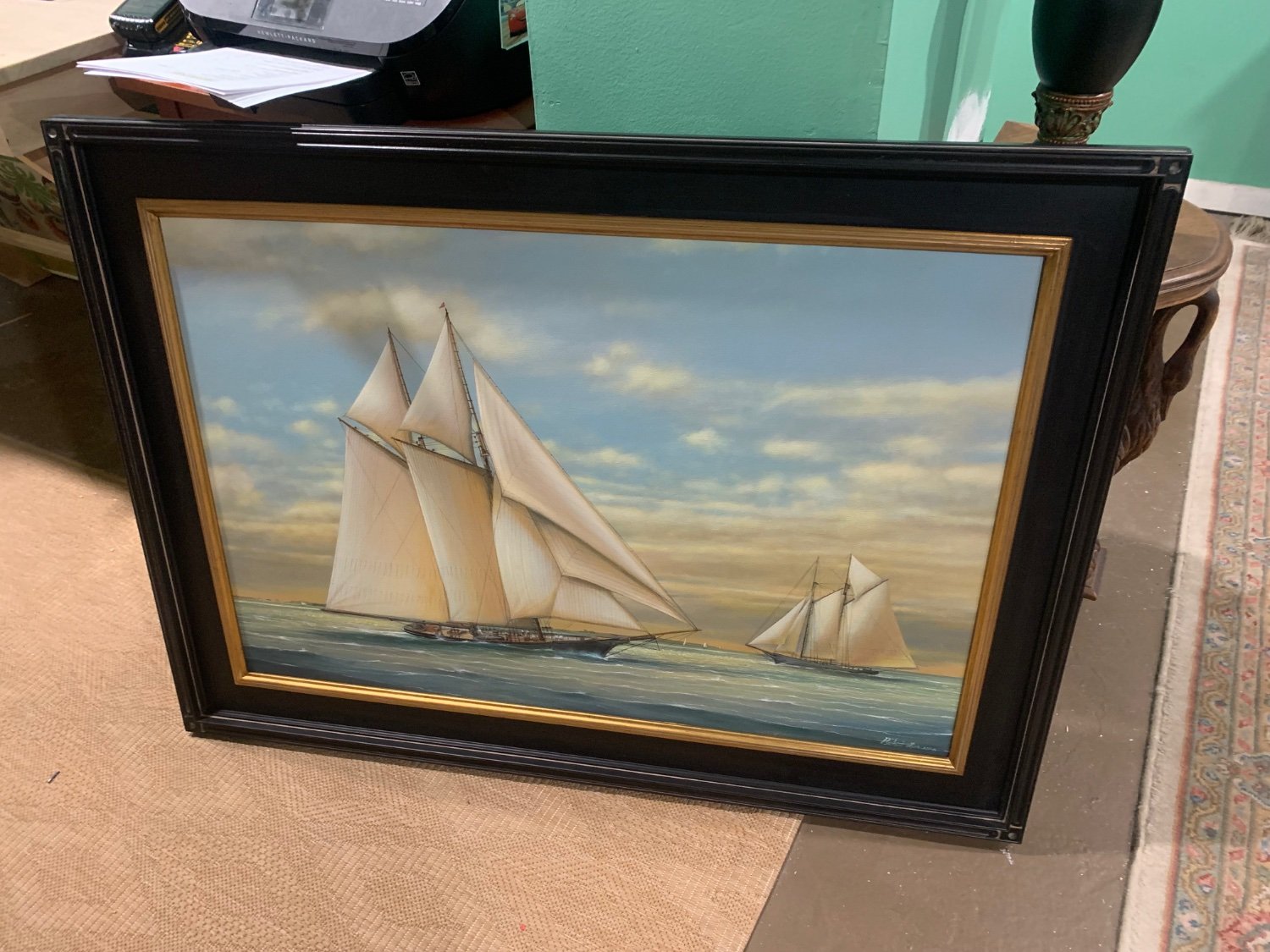
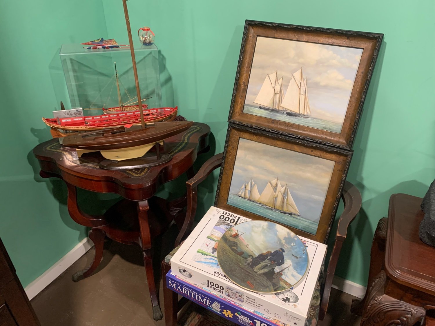
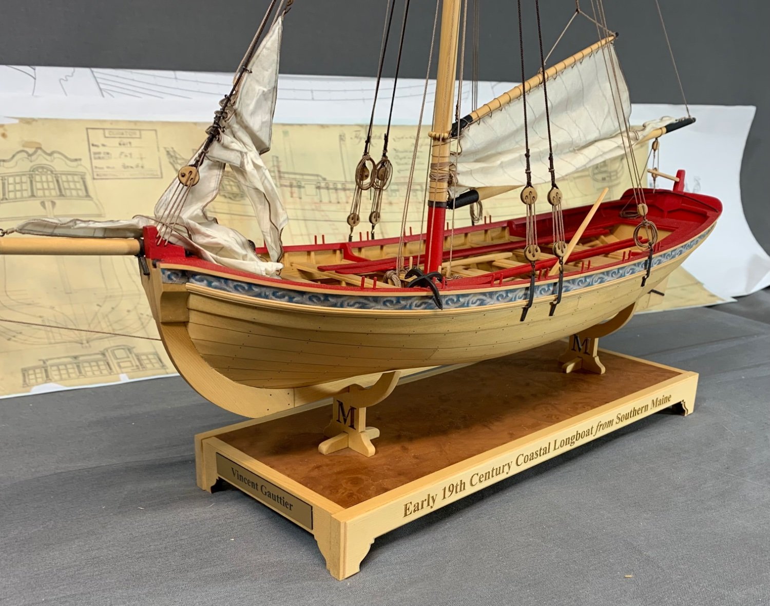
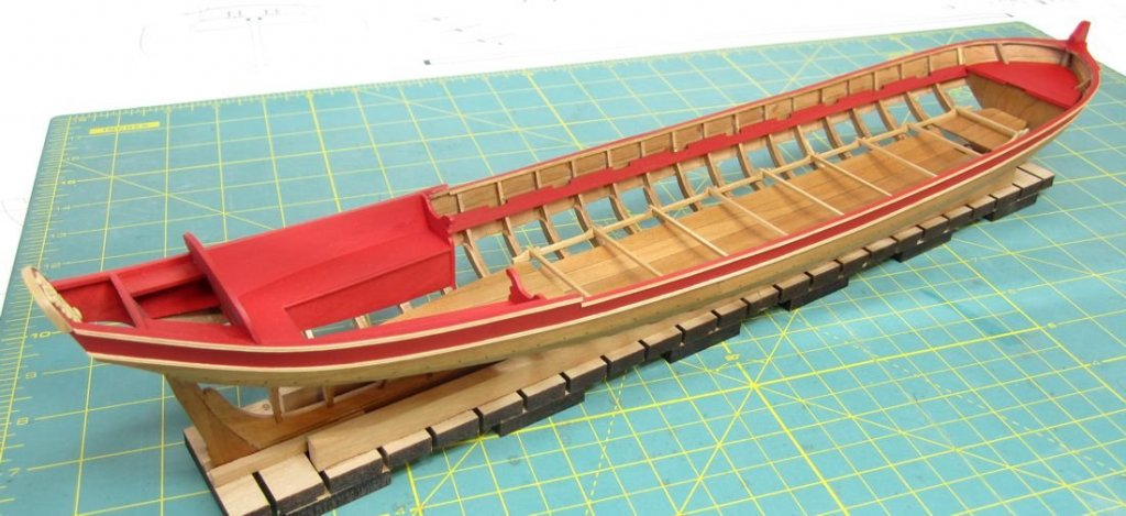
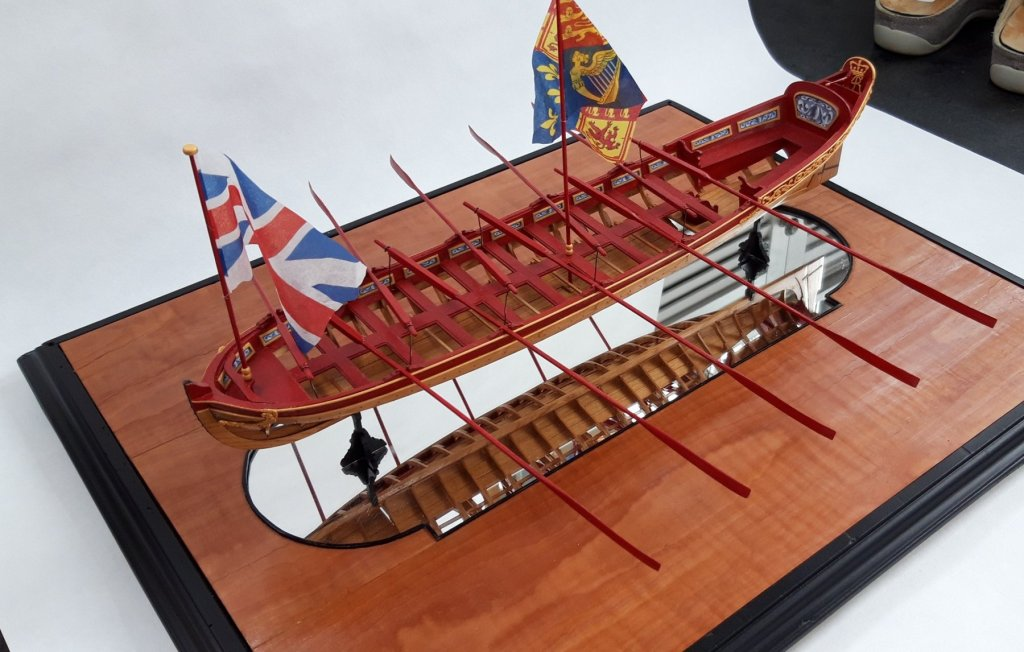
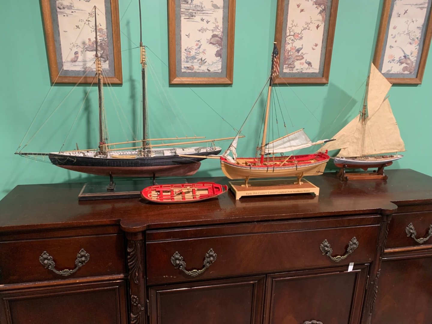
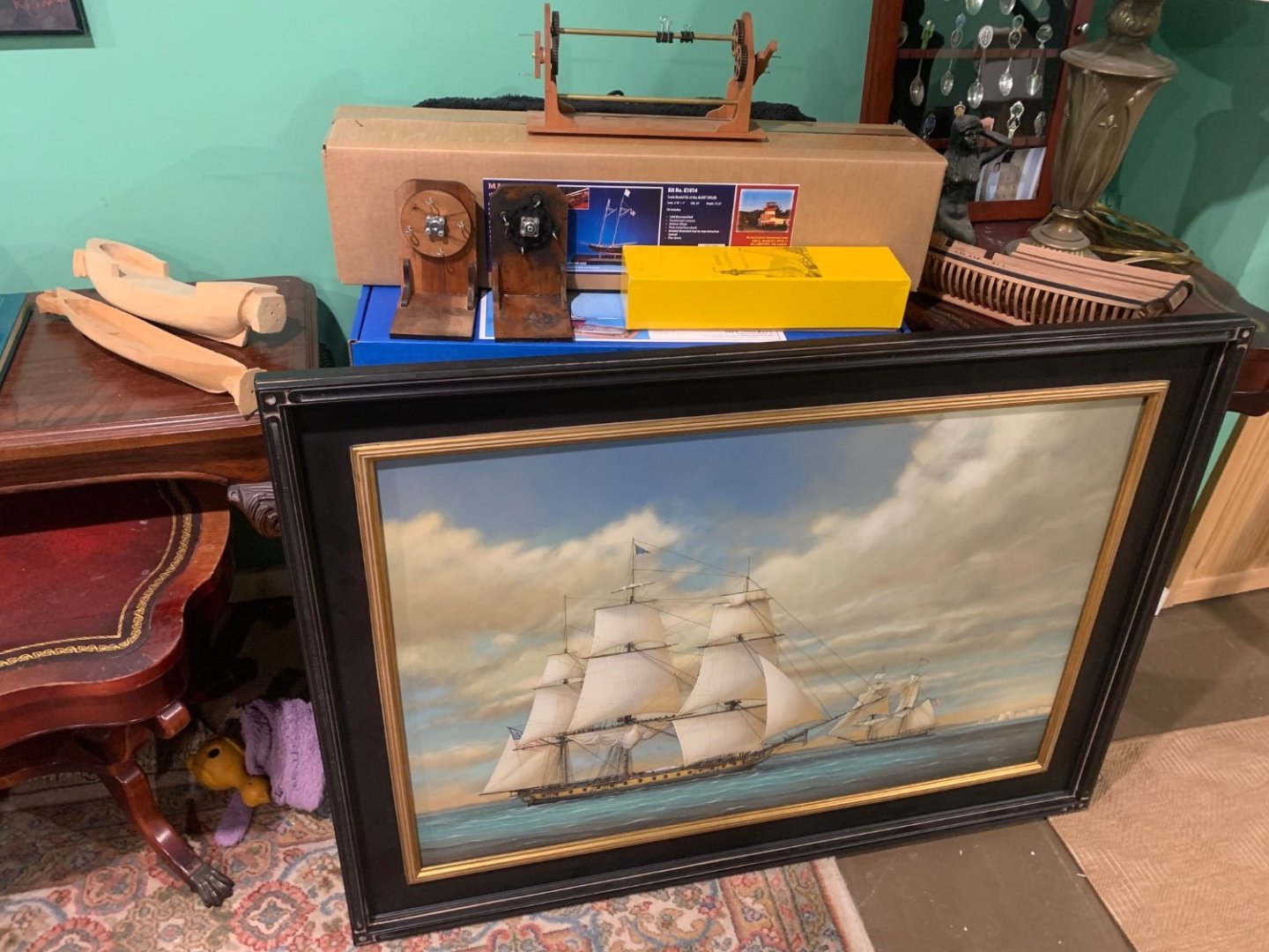
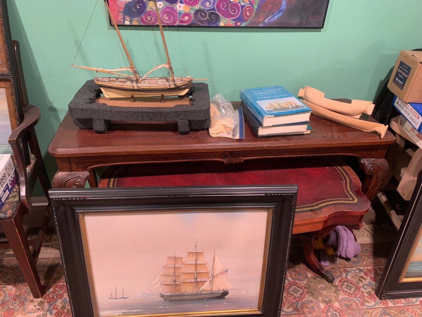
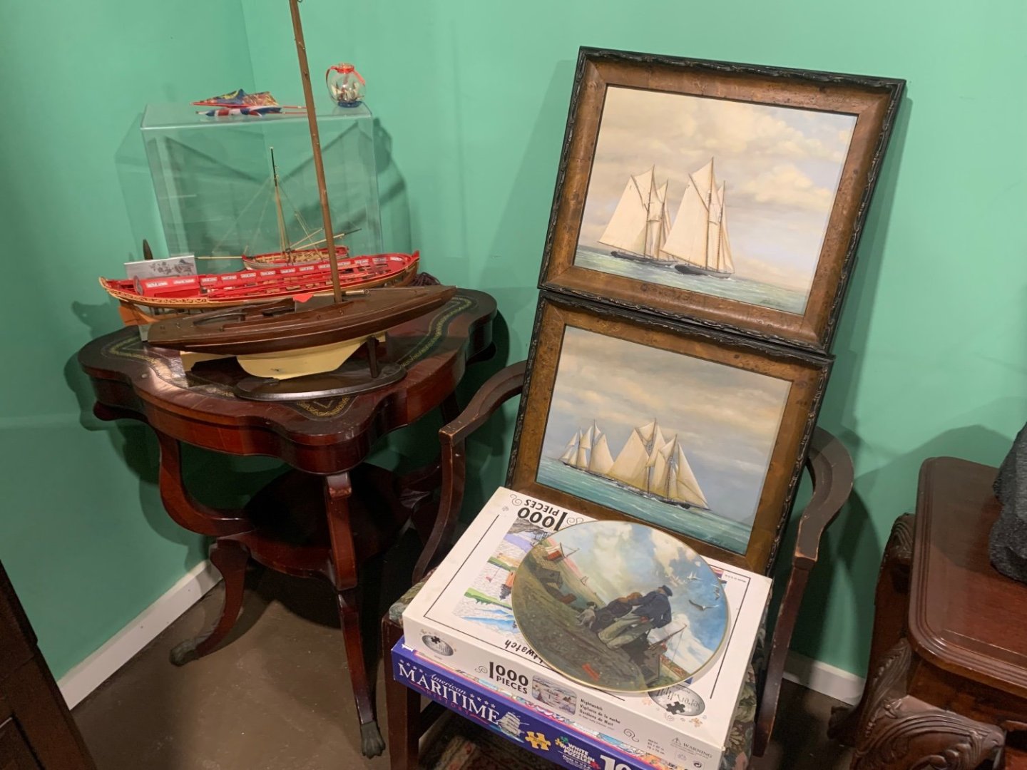
I just got back from the set where they will be filming. It was very interesting indeed. I brought about half of the ship models and tools needed to set up the house and workshop. I met some of the actors and an army of crew moving furniture around and staging the house. I have to be back there for the next few days as they get most of the heavy stuff done. Just a few of the items I am bringing. All this stuff is mine and also from my local NJ club members. The paintings will hang in a yacht club scene or two. Painted by my friend and club/msw member Richard Lane. Some of the models are his also along with Tom Ship Model (Tom Ruggiero) here on MSW and from local club. Some old tools and a kit stash etc. Old Nr Journals and books and an old Preac. My old ropewalks and serving machine. An old coffee mug from a Joint clubs conference,LOL and one of my old hats. You might notice my Longboat model is now American and the flag and name are changed for the movie…along with the Ed Harris character’s name on the side. I made the name plate in my laser cutter…all together a very interesting experience so far. The last photo shows how I will be setting up his workbench while he works on his longboat. There will be a junk scrap box and all around messy shop my own and many of yours.


-
Wonderful model and a wonderful cause....well done.
-
Funny! Yes it is quite the experience. The movie is called Riff Raff. Its a remake of an old movie. Should be fun. I will be setting up a garage workshop for them down to the sawdust on the floor. Filming has begun and I should be in the thick of it for a while. chuck
-
Thank you guys. Work will slow down for a while. I have been hired to help out on a feature film for the next couple of weeks. The lead actor is a ship modeler. I have been asked to help set up a believable ship model workshop and stage the home with my models along with others from my New Jersey club members. Its exciting and a once in a lifetime thing I just couldnt pass up. The lead character played by Ed Harris will be building my Medway Longboat kit in his workshop. How great is that…along with my tools and other things to dress up his garage workshop. I am going to help teach them how to fake it as a ship modeler. Starring Ed Harris, Dustin Hoffman, Jennifer Coolidge and Gabriel Union.
-
Thank you very much....I am hooked too. Chuck
-
That is a beautiful model. If you can tackle that kit you will have no issues with any other. That is a first-class model.
- 217 replies
-
- 3
-
-
- medway longboat
- Syren Ship Model Company
- (and 1 more)