HOLIDAY DONATION DRIVE - SUPPORT MSW - DO YOUR PART TO KEEP THIS GREAT FORUM GOING! (Only 72 donations so far out of 49,000 members - Can we at least get 100? C'mon guys!)
×


Chuck
-
Posts
9,672 -
Joined
-
Last visited
Content Type
Profiles
Forums
Gallery
Events
Everything posted by Chuck
-
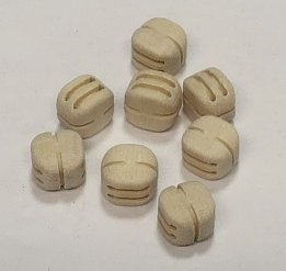
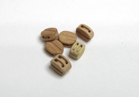
 1/8" single BARGAIN blocks are now in stock. I will finish this batch of 1200 blocks tomorrow and start on doubles. While I was busy packaging them up I decided to do a comparison photo between my Original Hand Made BARGAIN blocks and my new CNC blocks ...both are 1/8" single. In addition I added a Dry-dock single of the same size and took a brutal close up photo with my phone. I dont know what all the fuss is about with the other guys blocks. I only had a package of their pear versions...if that is actually pear I dont know. In addition I was pleasantly surprised at how close my old hand-made blocks look to my new CNC versions. I am glad I have help now to make both so its not a chore to make either of them. Having worked for the last 10 months at those CNC blocks it certainly help me improve my skills when it came time to make them by hand again. I hope you dont mind me saying that I am pleased with the results for the hand-made Bargain blocks. Photo Just for fun!!!
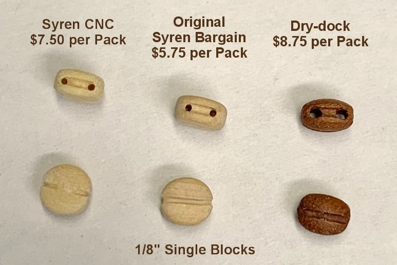
-
I dont think Im in any of those pictures. I was taking them. I will look through them all and post one. Chuck
-
HM Cutter Cheerful 1806 by Erik W - 1:48 scale
Chuck replied to Erik W's topic in - Build logs for subjects built 1801 - 1850
Outstanding -
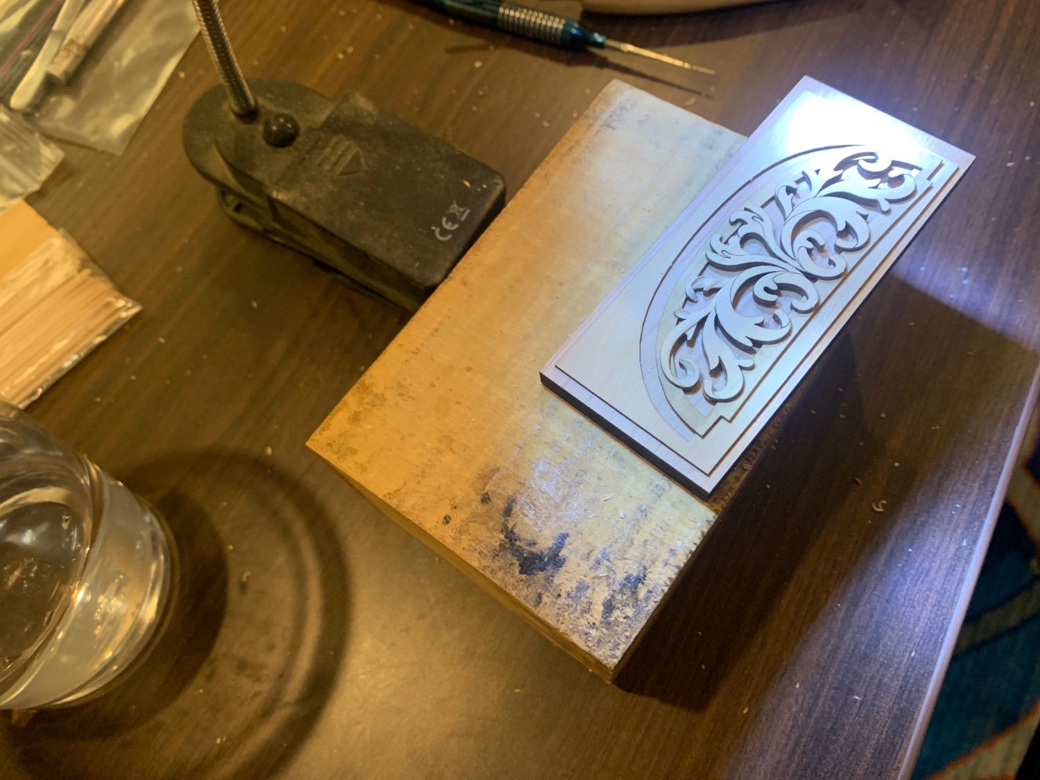
Boxwood or Swiss Pear....we had both to experiment with.
-
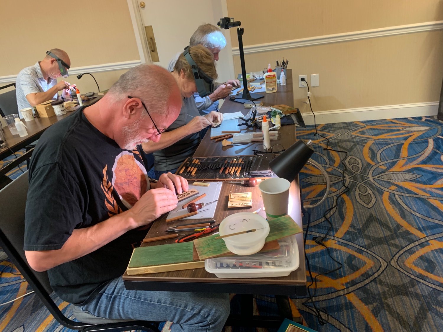
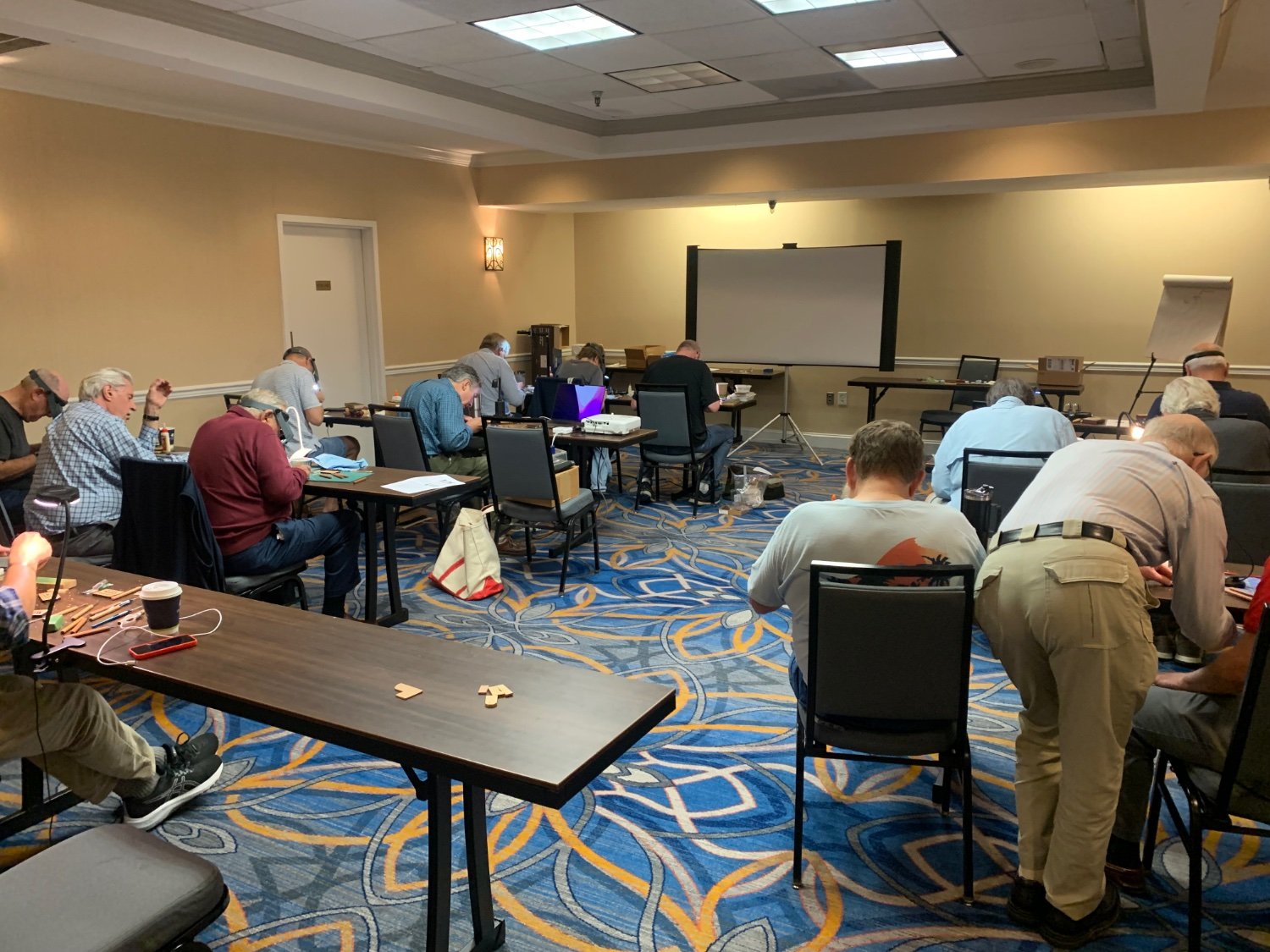
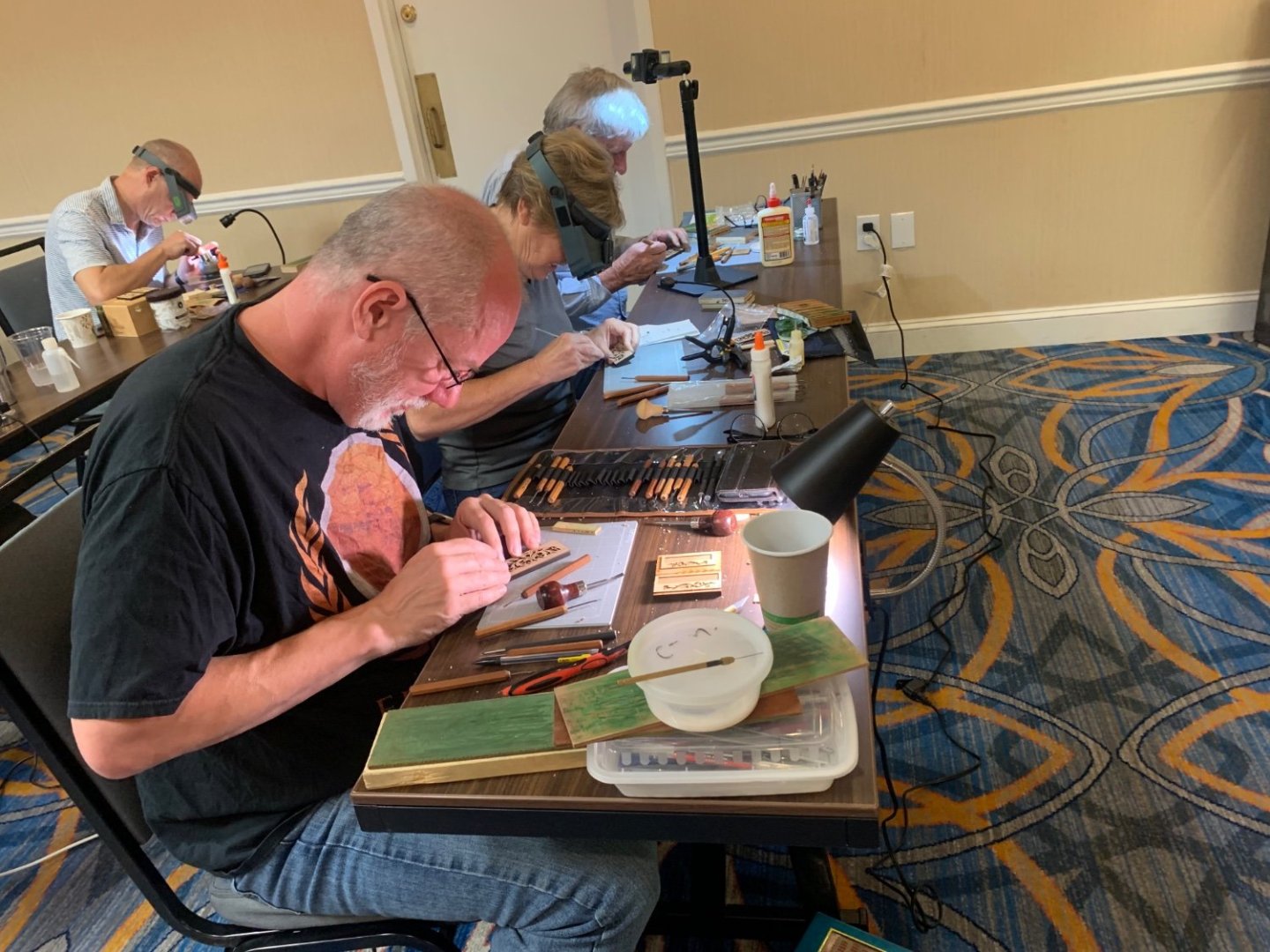
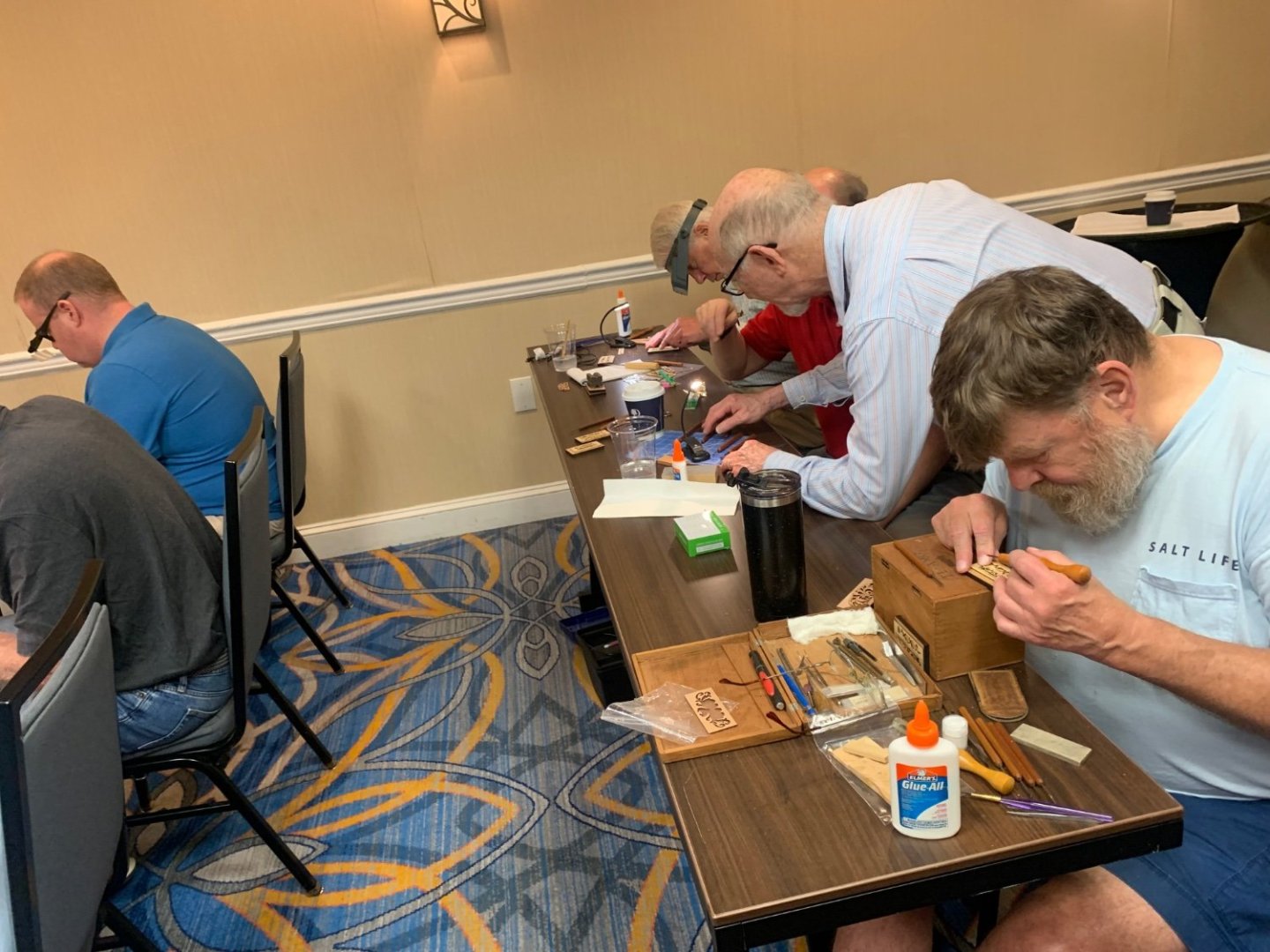
Everyone had a great time at the carving workshop and tour of the Naval academy. It is always great to see all guys and gals. A special thanks to David Antscherl and Greg Herbert. Chuck
-
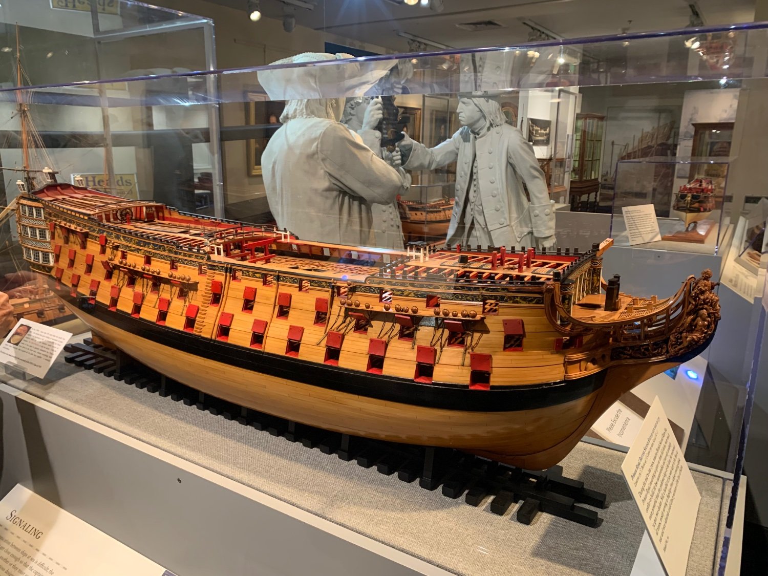
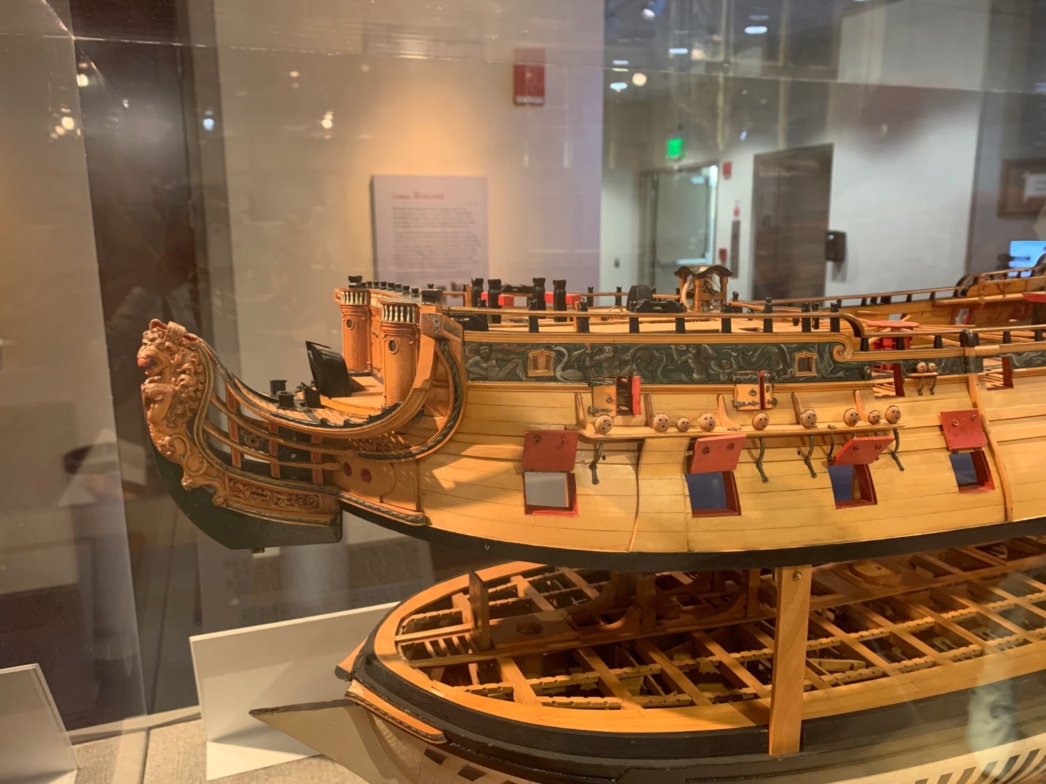
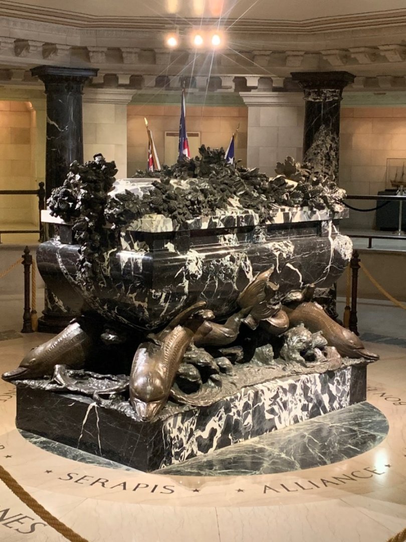
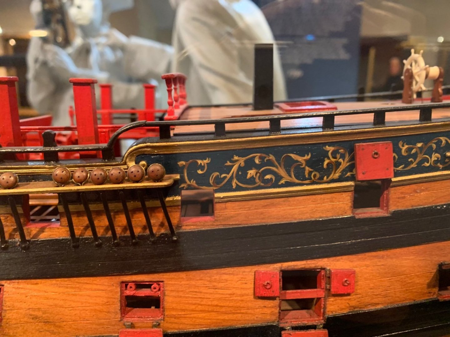
You have my older rope packages. A few years ago I decided to make the rope lengths longer but keep the price the same. Just to give folks a bit of a break with inflation and rising costs. I am still maintaining those prices. Yes that is 29 to 30 feet. My store will reopen sometime today. I just returned from a trip to Annapolis and the Navy Yard Museum. Below for example is the Crypt of John Paul Jones. Chuck


-
Welcome back Ken.
-
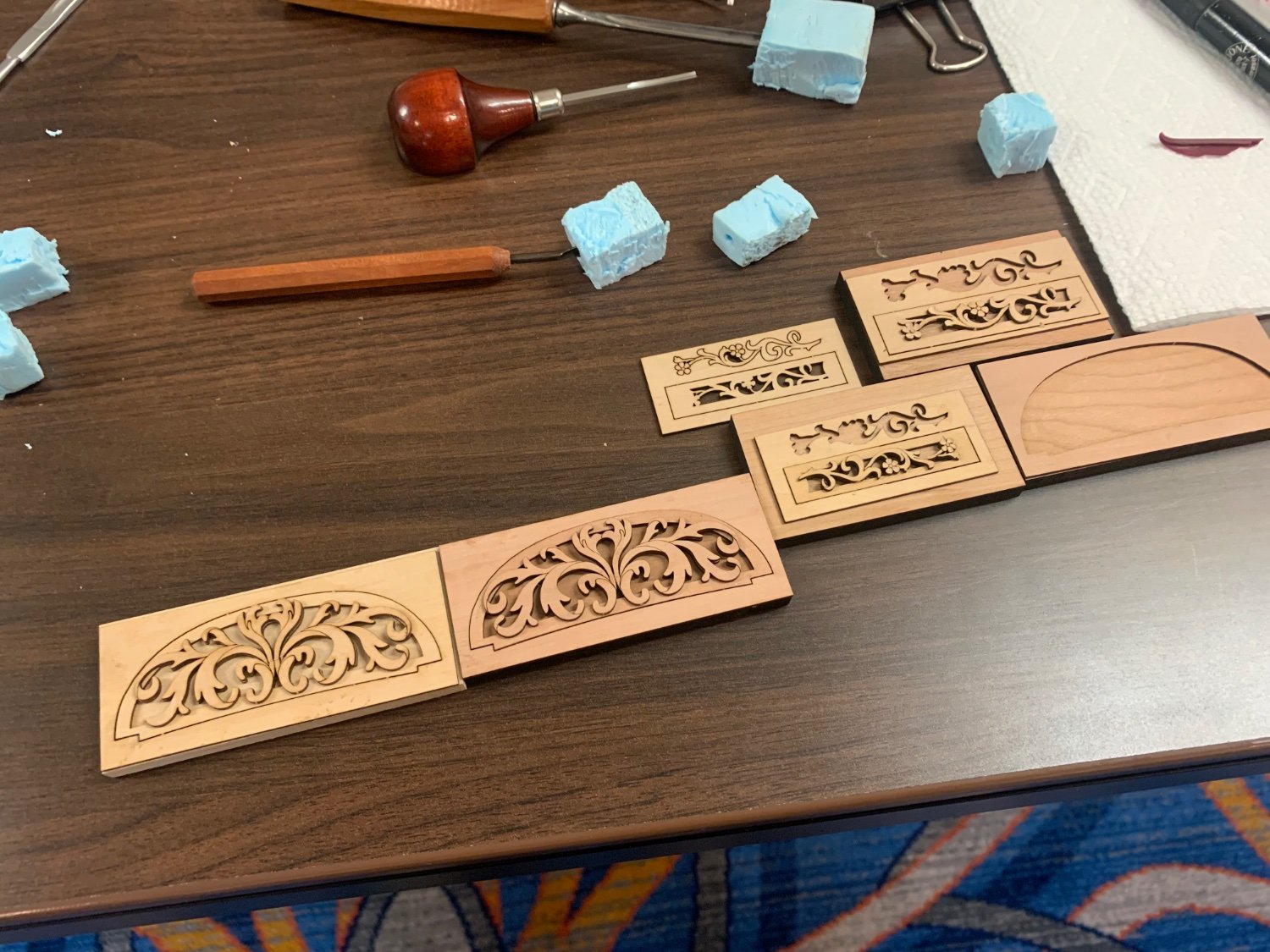
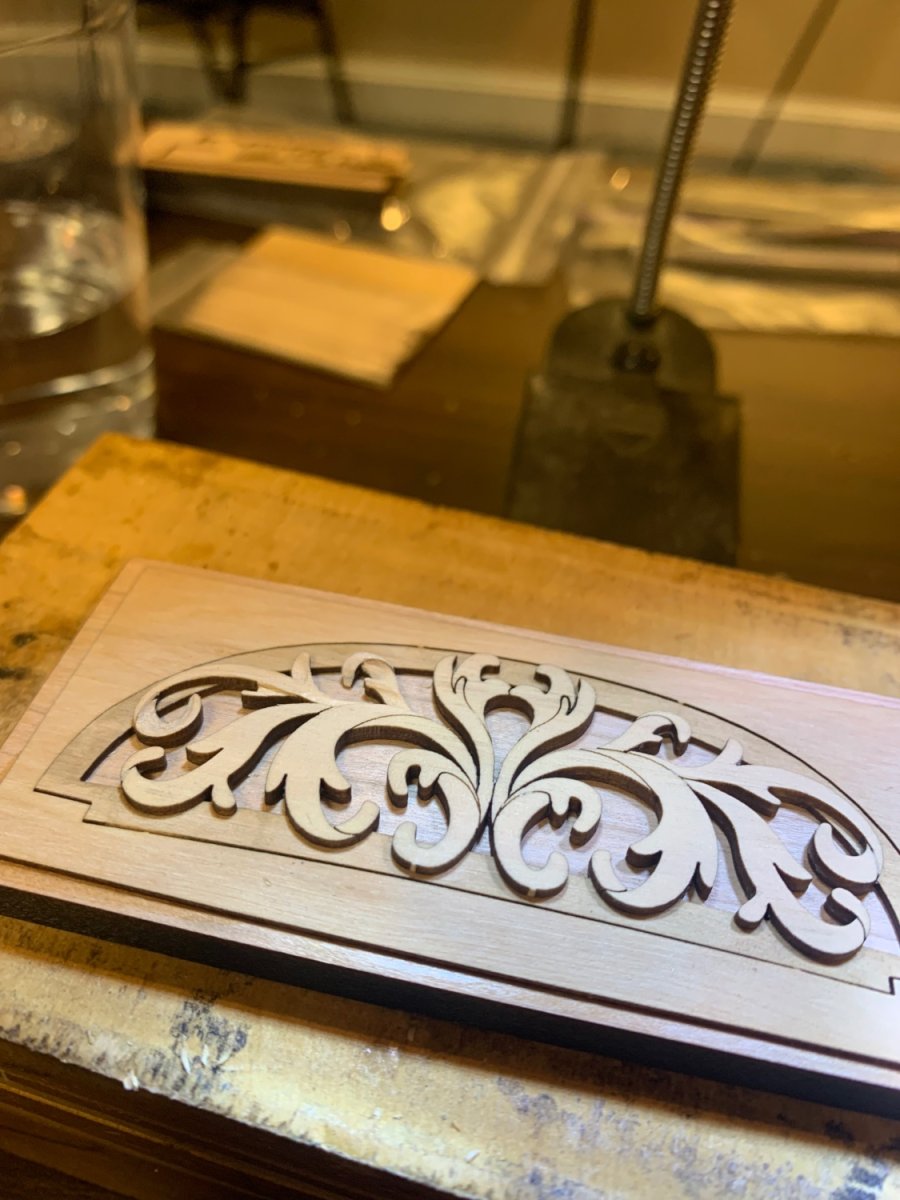
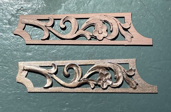
Yes indeed. We started with relief carving and the initial pieces were all laser cut blanks. Then we moved onto some gun port wreaths. A lovely time.
-
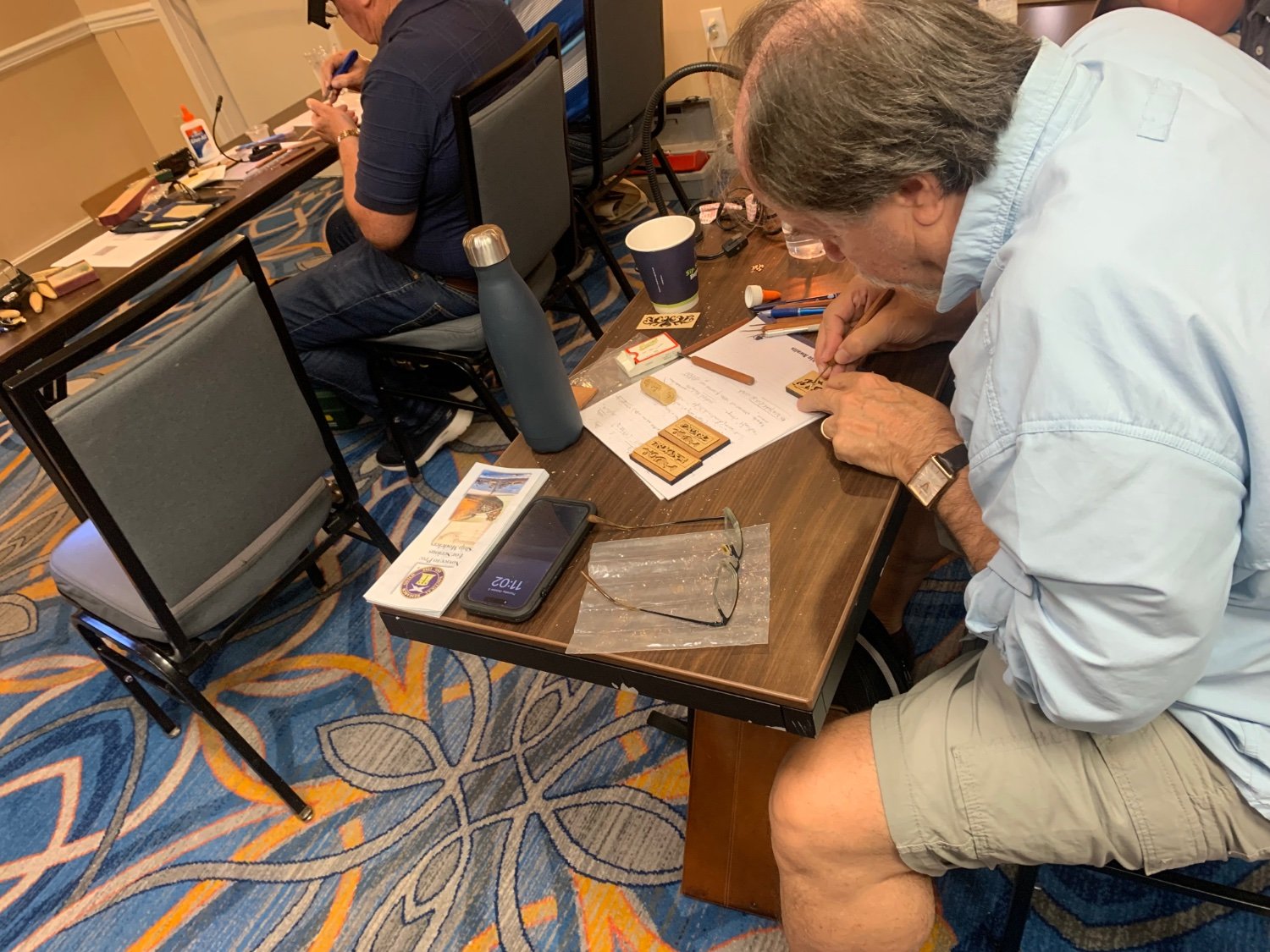
Everyone is quietly and carefully micro carving!!!! Admiralty carving workshop 2023. so much fun…


-
Thank you guys. Hopefully will have more updates soon. Currently I am down in Annapolis MD for the Admiralty Modes Carvings workshop. It is so much fun. Chuck
-
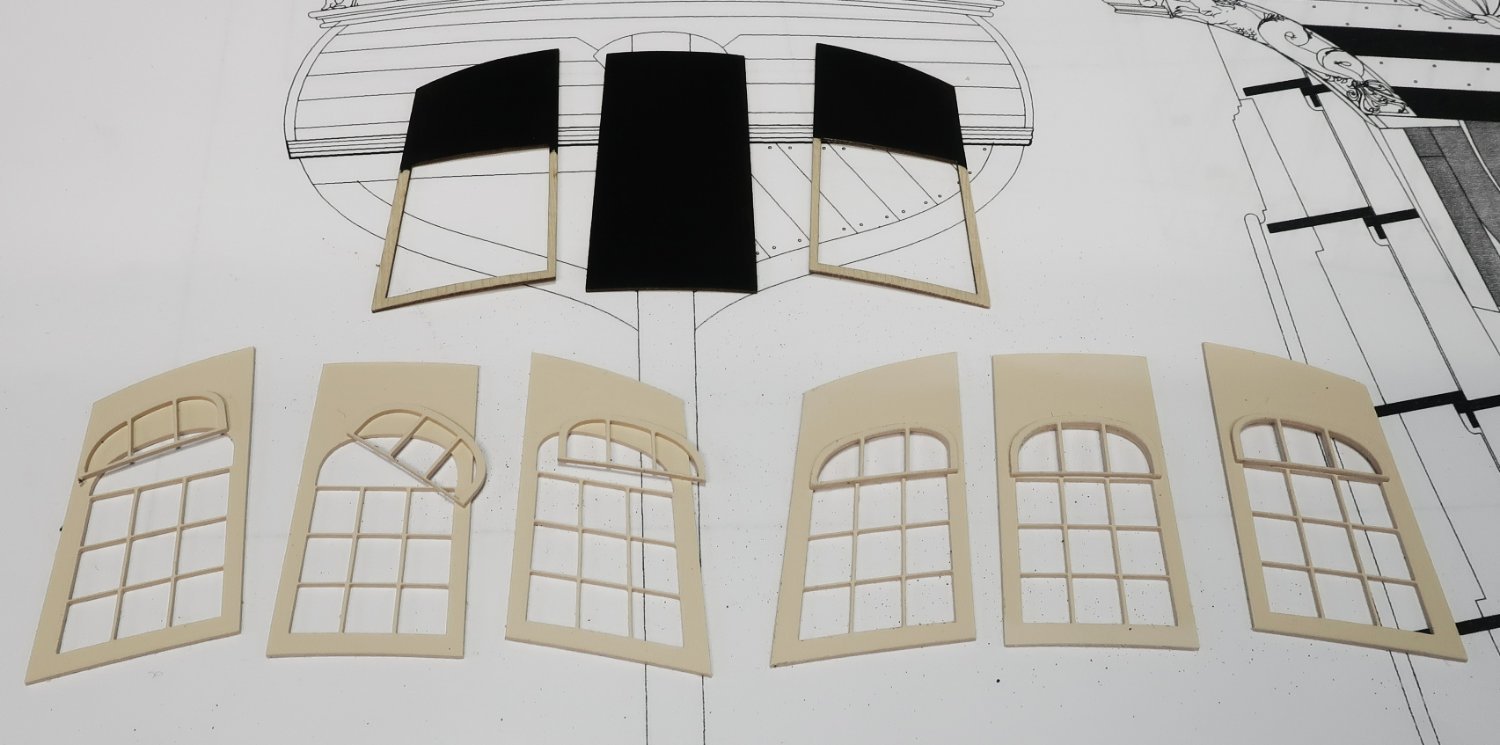
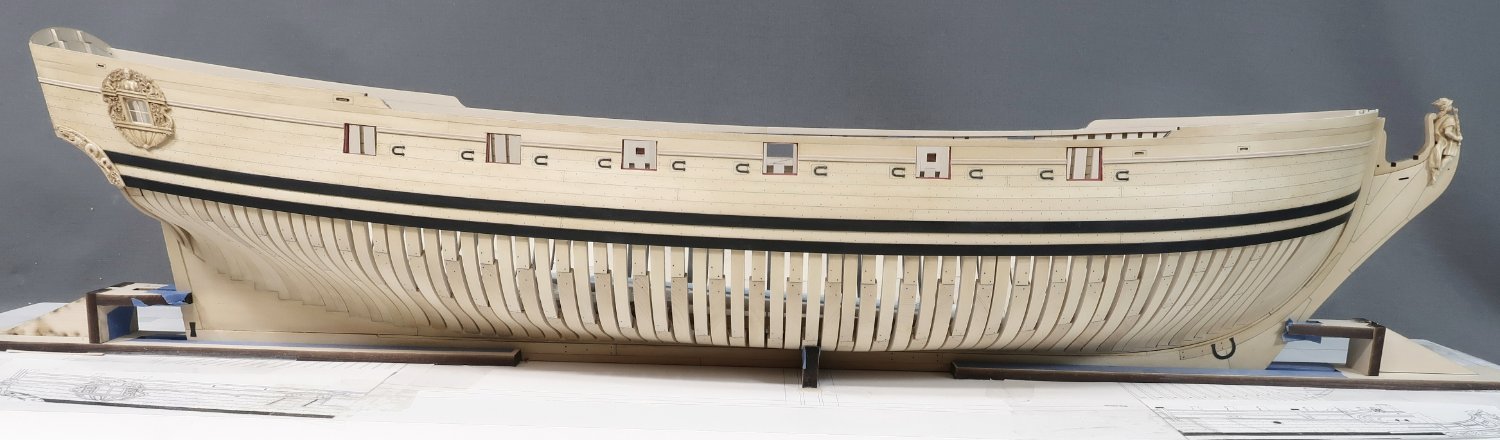
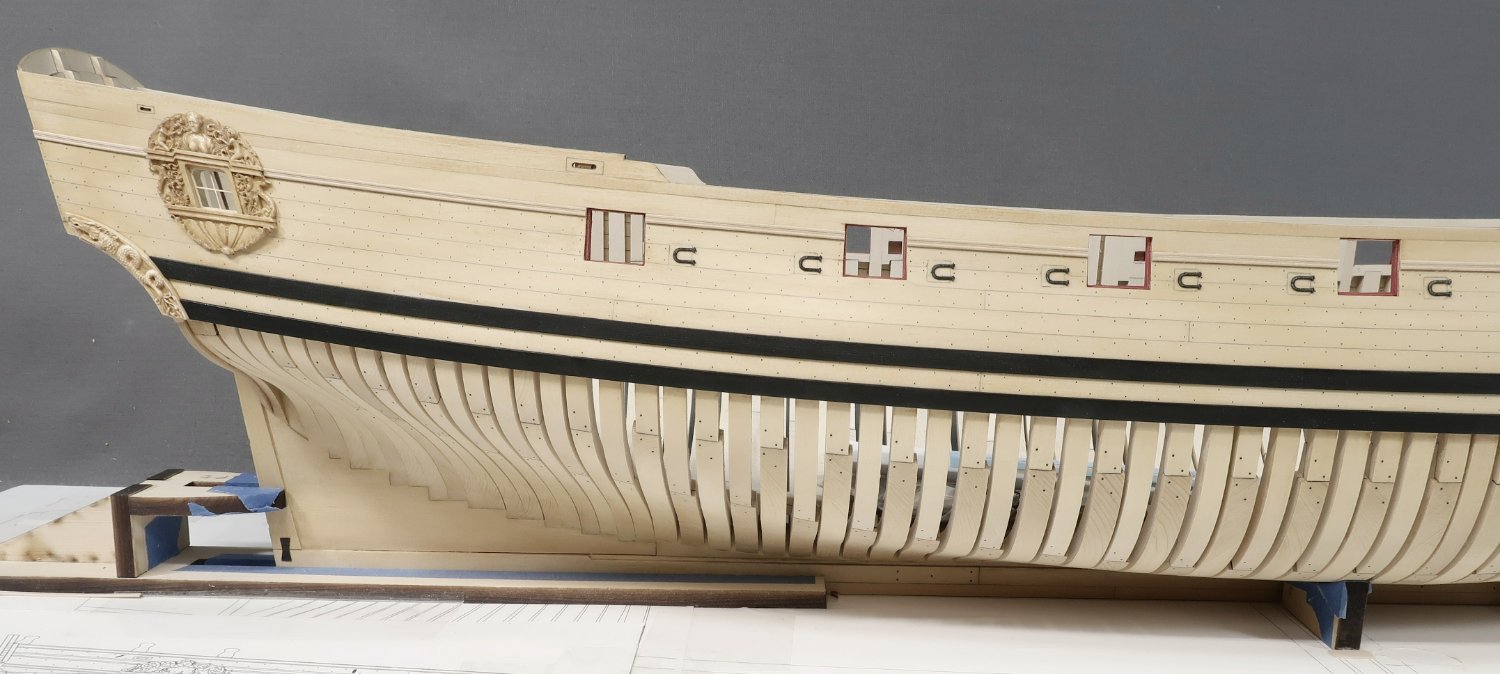
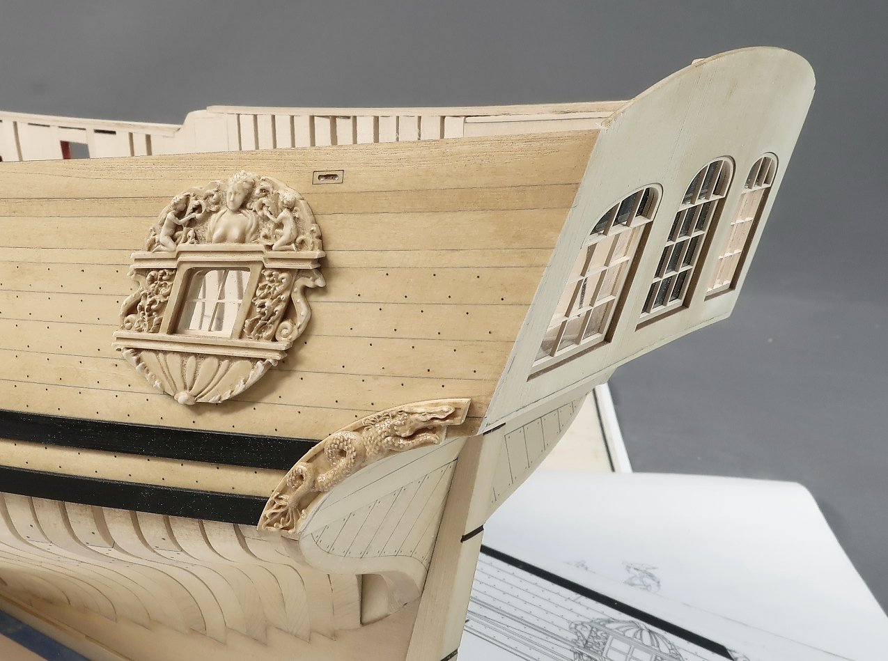
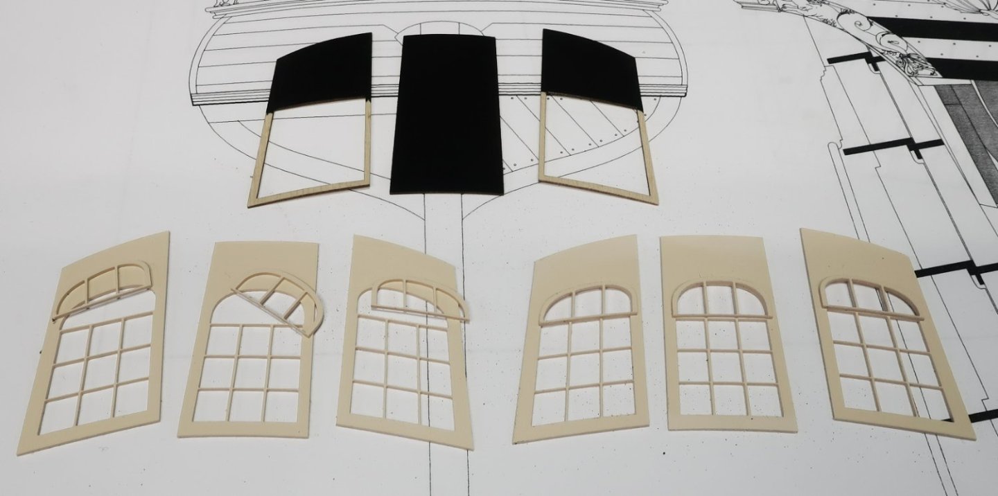
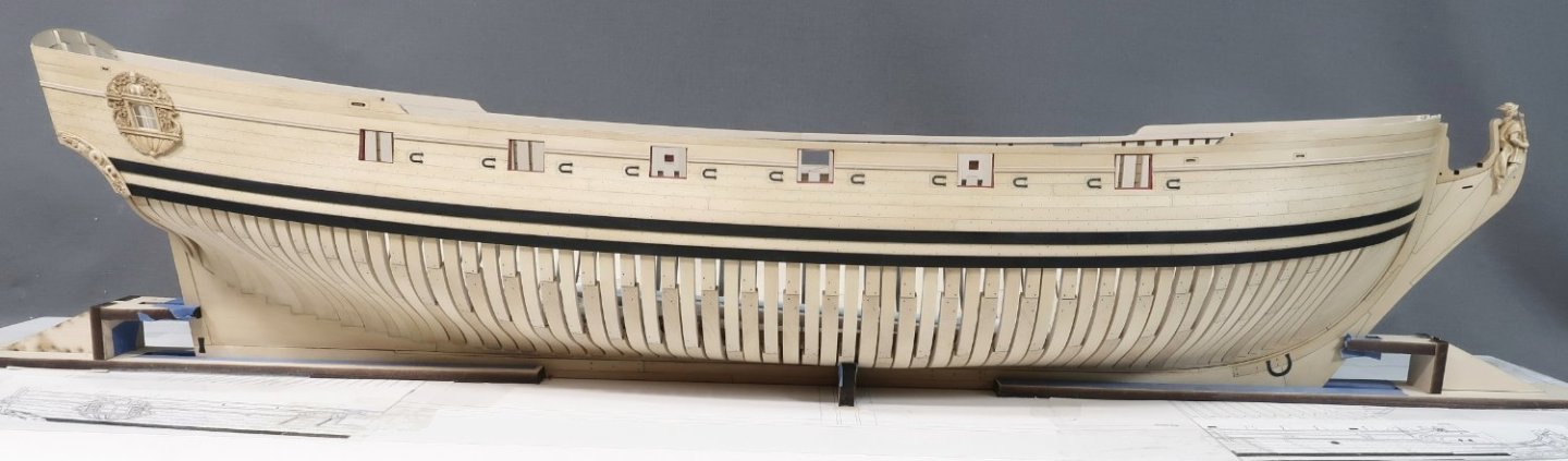
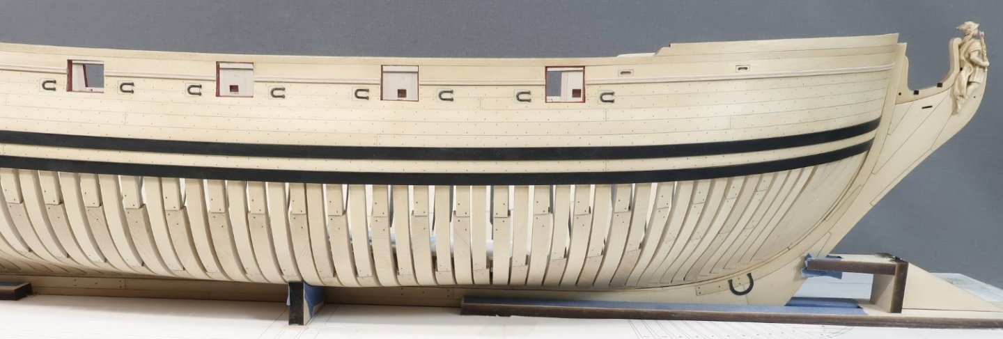
Its been a while since I worked on Speedwell. But I managed to steal some time to get some minor progress done. The next step was to permanently add the stern lights. I glued the laser cut stern lights together as shown. There is a little top portion that is glued on top of the larger laser cut stern lights. In addition, there are three laser cut cedar inboard pieces shown on the top of this image. The aft side is painted black/Gray where the stern lights are false. Meaning they wont be windows you can see through. It may be difficult to tell but the stern lights are placed in the appropriate openings from the inboard side first. Then some laser cut acetate used to simulate the window glass is placed in the same openings from the inboard side. Lastly the painted laser cut pieces are placed on top as the final layer with the painted gray portion facing outboard. With these glued into position I will be able to plank the inboard side of the hull next but only the two strakes along the sheer. Instead of doing that however I decided to add the sweep port hinges and horse shoe plates to the outboard side of the hull. This can be done whenever you like really but I figured why not do it now that I am in the mood to see the hull with some details. The sweep port hinges are available as a laser cut min kit. I have several sizes but these are the "large" hinges I have developed. One package is enough for Speedwell.

-
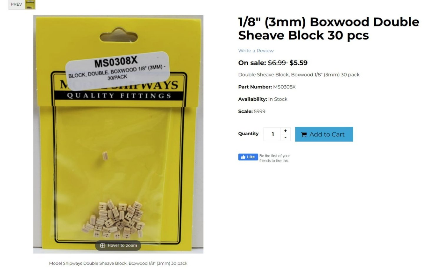
Crazy thing...I rarely shop for rigging blocks for obvious reasons. But I was searching online for info on rigging blocks so I can start making CNC fiddle blocks and Hearts... LOL...I came across the typical square blocks which are abominations that come in most commercial kits. I couldnt believe the price. They are selling these things for $5.50 per package of 30. It just hit me that my bargain blocks are the same price....I think my bargain blocks are a steal for the price. I cant believe how out of touch I am when it comes to how much money folks are charging for this stuff. I thought they were maybe charging $3 for a package. Crazy stuff. Anyway....enjoy them while I can offer them. I should have another size in stock tomorrow some time.
-
Thank You I havent tried but I dont know why you would do that. At least once the pear blocks are available I mean. But while you wait You could try dying them. Several people do that and it looks great. Greg Herbert did that with my blocks on his Speedwell model. These are basically my BARGAIN rigging blocks dyed with Fiebing's dye. You can see these are darker than those posted by the other Greg...I dont know what color dye he used or how long you have to soak them for.
-
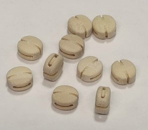
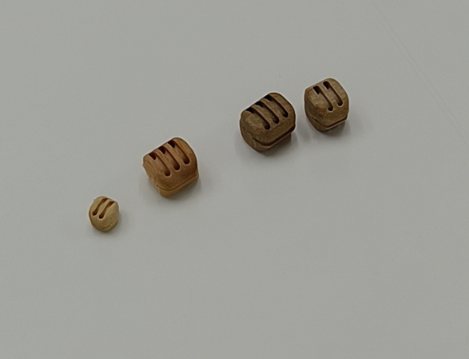
I really dont know if they are being resold. yes I hope to also have pearwood blocks but first I have to get it so I am fully stocked with boxwood. So it will be a while before I have those. The two on the right are a test in pear. The second one is a different mystery wood that I liked and tested. Its a beautiful lighter brown color. The first is boxwood. Chuck
-
Its crazy stuff…i cant fathom it. chuck
-
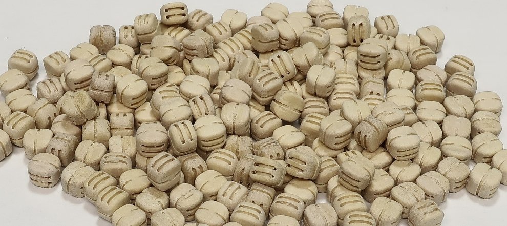
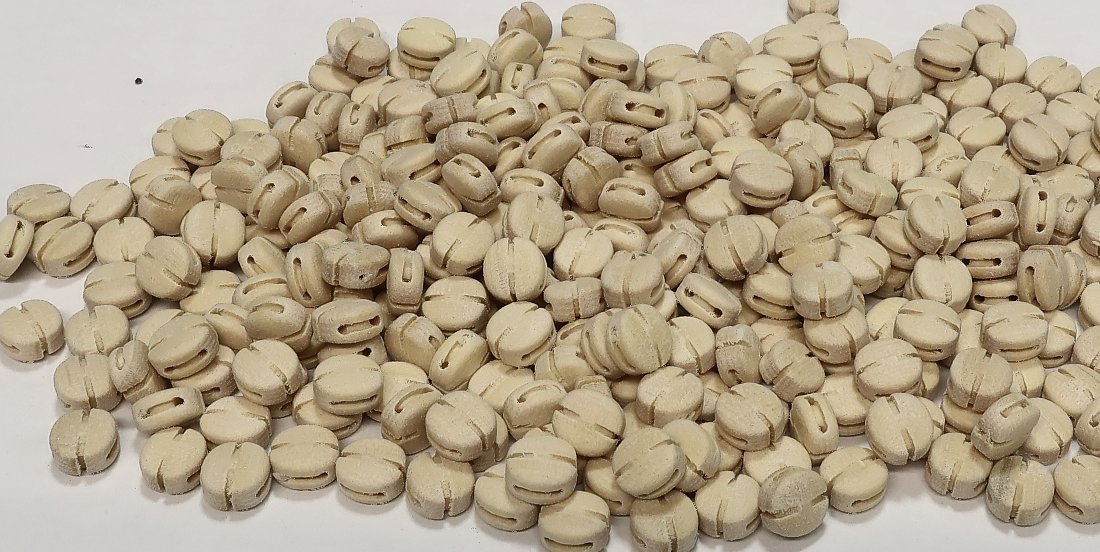
Less than 24 hours after placing thousands (seriously thousands) of rigging blocks for sale on my site.... Yupp, you guessed it. Nearly sold out. Will be making more but seriously this was a lot of blocks. Keep checking back to see when they are restocked. It will take a while to get fully stocked at this level of demand. But I will do my best.
-
I have one LOL But I want cull out any bad or chipped blocks so it will be slow going. Chuck
-
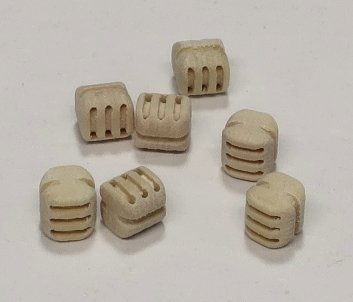
I have them all. I just have to update the site and get them all packaged up. This includes a new larger size of 9/32” single double and triple blocks. Some sizes are in short supply for this initial batch but I have more on the way. Probably today and tomorrow I will have the packages up. I have lots of labels to stuff i to small bags for the packaging. That takes a while. chuck
-
Very nice progress. chuck
-
Getting close now.... Check my site regularly as I start to package these up later in the week. They have a bit of sawdust on them but I get them in bulk....so some dusting off before packaging them up is in order. A huge thank you goes out to Jack for his hard work these last six or seven months helping to make these a reality. He is a super knowledgeable guy when it comes to cnc.