HOLIDAY DONATION DRIVE - SUPPORT MSW - DO YOUR PART TO KEEP THIS GREAT FORUM GOING! (Only 13 donations so far - C'mon guys!)
×


Chuck
-
Posts
9,660 -
Joined
-
Last visited
Content Type
Profiles
Forums
Gallery
Events
Everything posted by Chuck
-
 They look great Frank...Cant wait to see an overall shot of your hull from the stern quarter when you get it all done.
 -
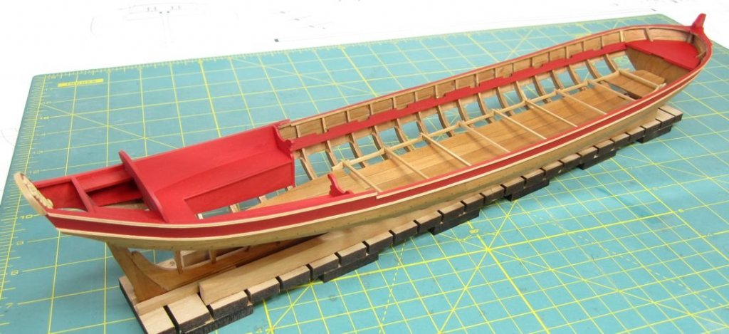
Stretcher boards. Long boards sit in those "V"s which the rower then pushes against with their feet.
-
She looks fantastic. I hope you enjoyed the project. Your model looks wonderful.
- 137 replies
-
- 2
-

-
- winchelsea
- Syren Ship Model Company
- (and 1 more)
-
Cheerful build query
Chuck replied to CaptnBirdseye's topic in Building, Framing, Planking and plating a ships hull and deck
The cutter Cheerful as well as many small cutters from this era did NOT have a false keel. Please disregard that info so as to not get confused with your dilema. But as to your issue at hand and considering the terminology... you probably just need to sand back the aft side of the stem assembly. Basically sand where it initially touches the BH former rabbet strip. This will easily close up the gap above it and below where it initially touches. It doesnt even have to be completely closed up as long as you get a decent glue joint for most of the length of the rabbet strip along the stem assembly. Remember to have fun with the project. I also encourage you to start a build log. I couldnt find one but it would be so much easier for the folks who have built the Cheerful to help you as you proceed. Chuck -
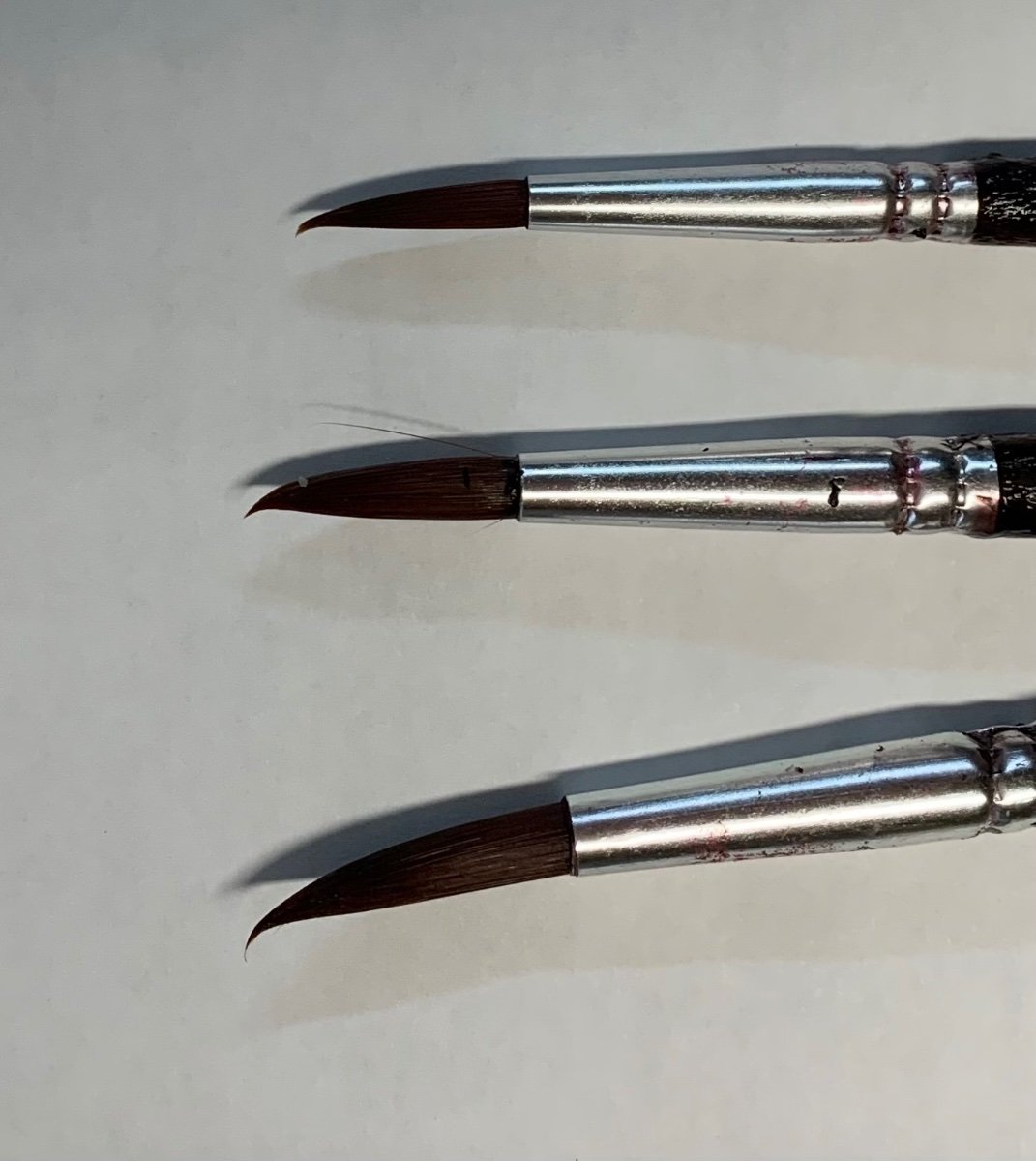
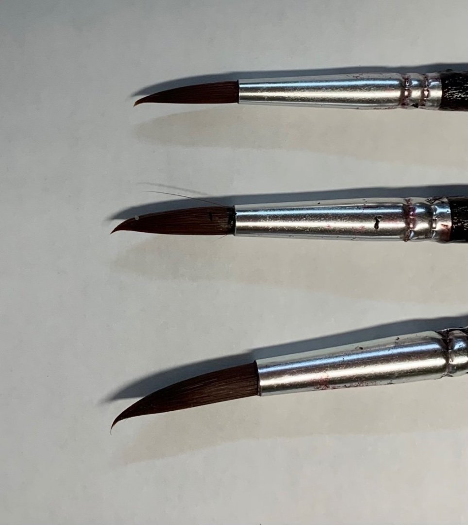
Well, simply put...there is no reason to wait in order to paint. Its best to have painted those areas before they became hard to reach. Usually that is best when planning. It is much easier to do a bit of touch up later and dust can be cleaned away without hurting the painted surfaces. Having said that...I do keep several brushes of good quality in a cup of water all the time. I do this to actually force the tips of the brush to bend and keep the bend. This allows me to apply a bit of paint to the tip of the brush which can be used to get in some tight spaces. But not that tight. It is always best to paint parts before they become inaccessible. I have other brushes with even more of a bend. These are three I had readily at hand.
- 18 replies
-
- 13
-
-
That is my hope....if I can do my small part. I do get vetoed a lot. The movie isnt about ship modeling but the guy just happened to be a an experienced intermediate kit builder. Many scenes will take place in the garage workshop. I have a gigantic pile of old journals and seaways ships in scale mags to leave scattered throughout the house....LOL. But they keep taking them away. Its pretty friendly though. I mentioned that my admiral doesnt like my ship model stuff all around the house either. Then puzzled.... they asked me...."Your Admiral?" I explained that many ship modelers refer to their significant others fondly or even not so fondly as the admiral. They all laughed and have decided to write that into the script...LOL. They want the guy to be a real ship modeler. One scene the wife enters and breaks a model and yells at the actor to clean up all the sawdust and mess. Sawdust I happily swept up from my shop floor the night before. Chuck
-
I was busy today and missed this thread but I will add that early on our members were actually scammed on MSW. This happened exactly how one would expect. Someone pretended to have lost a relative (father) and had their stuff from 30 years of ship modeling to sell. He listed them all and took PayPal payments and nobody received anything. Thousands of dollars worth of tools and kits and books. It was a complete and total scam. By the time we suspected and found out...the email was disconnected along with the paypal address. Photos of the stuff were pasted from the web etc. This is what prompted our rule about 25 posts (originally 50) and for folks who sell stuff to be vetted or be members in good standing. But yes it is always buyer beware. It is too easy to get scammed these days. It usually happens around the holidays too!! So please...damned if we do and damned if we dont. I would rather have folks here be mad at us for protecting them rather than screaming at us after they were scammed here out of not so insignificant $$$....It is for our community protection. We have always had exceptions. Most folks contact either me or Kurt and we make it so they can create a topic here. We must have missed this one and they never contacted us directly. But usually we know these guys who passed away and even their relatives. So we vet them ahead of time and endorse them when they finally make a post about the stuff. If you dont see that, please be aware its all your risk. But if you dont see such an endorsement...please bring these topics and posts to our attention so we can do our due diligence and make sure it is legit.
- 11 replies
-
- 19
-
-

-
No winnie…only small boats. Lots of half built models from my shop just placed all over in his fake workshop. But once I have it all set up I hope to have actual pics…maybe with some of actors if they would allow it. But there are so many freaken rules.
-
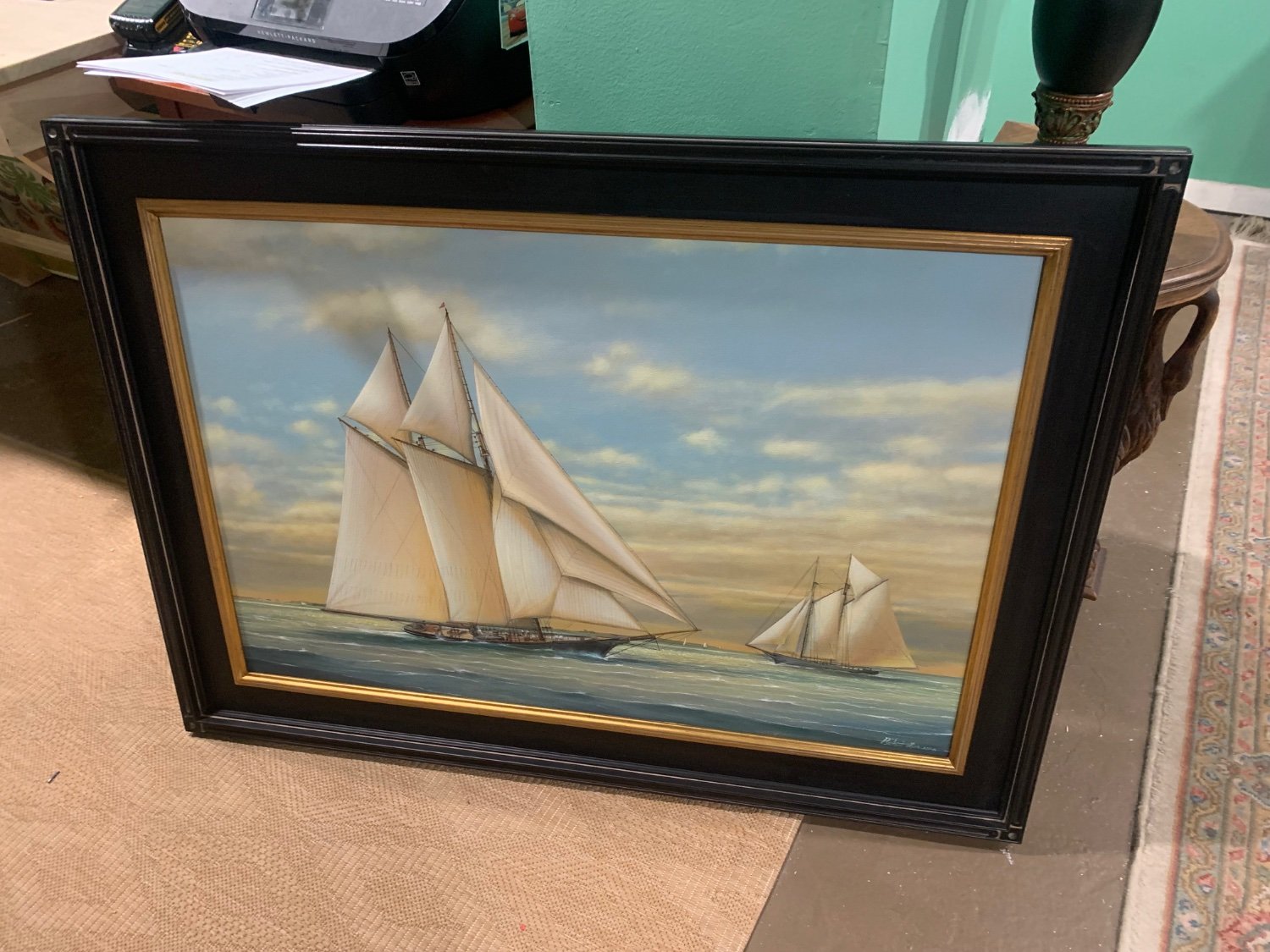
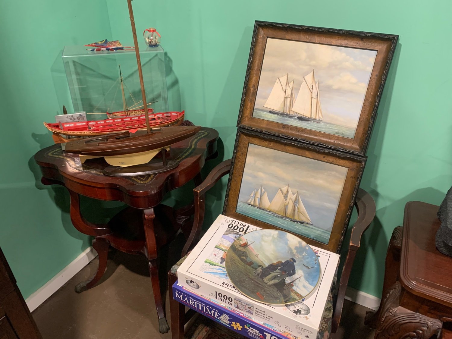
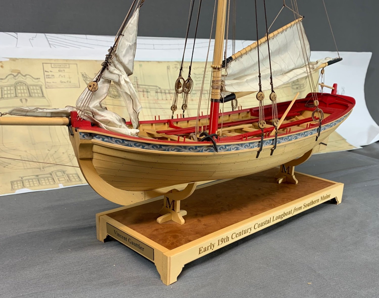
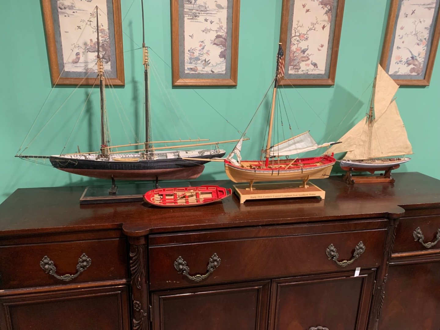
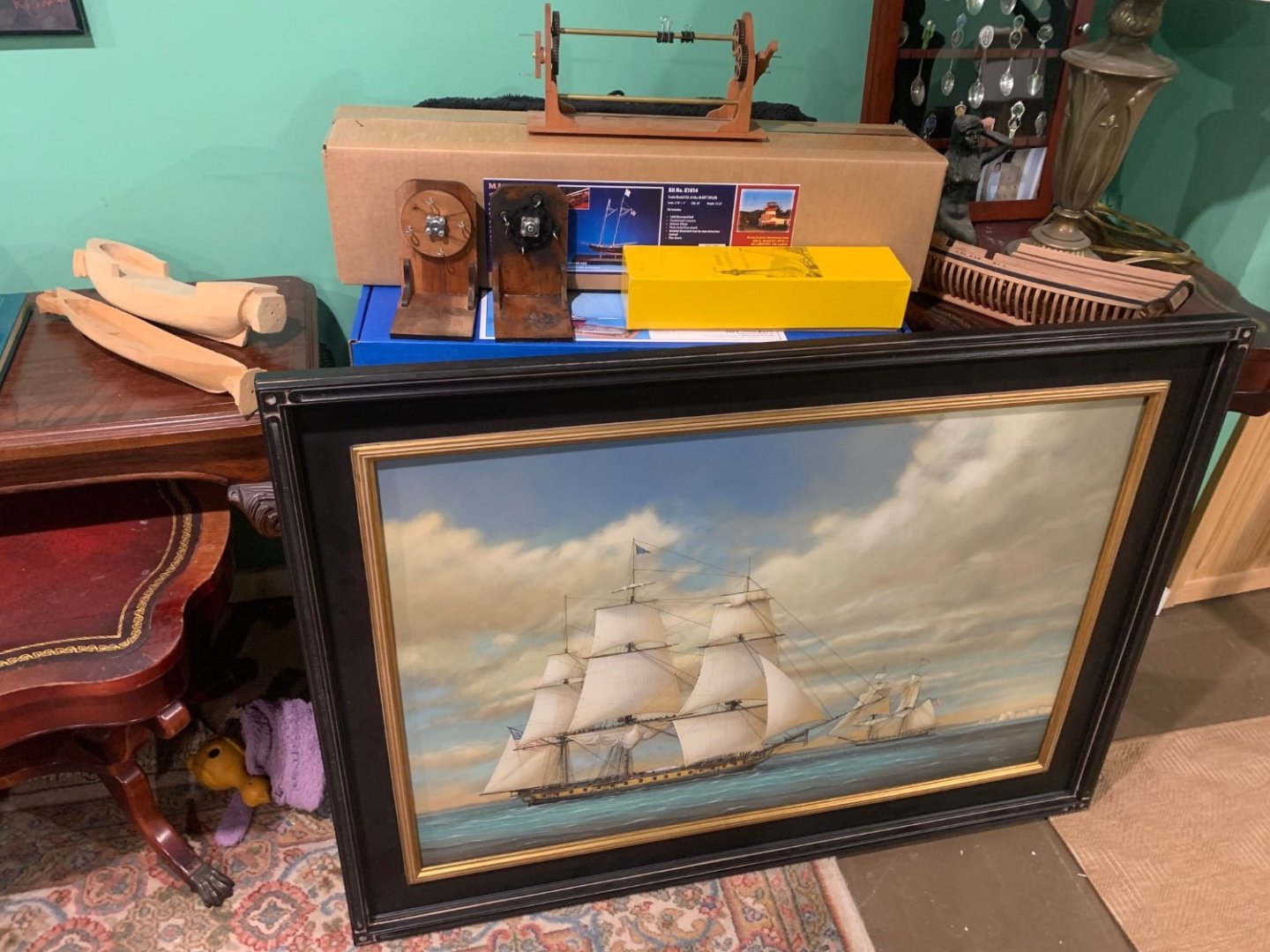
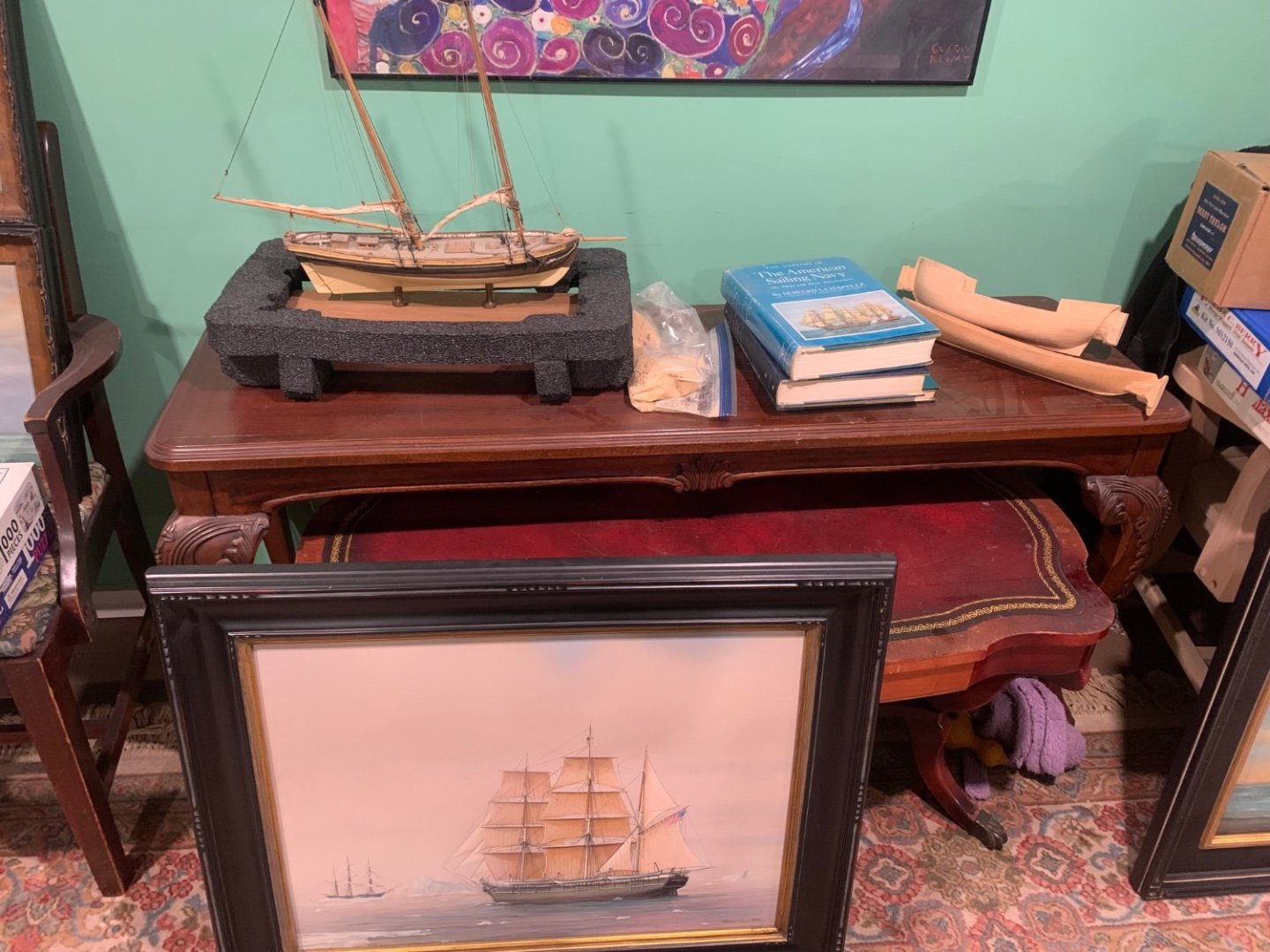
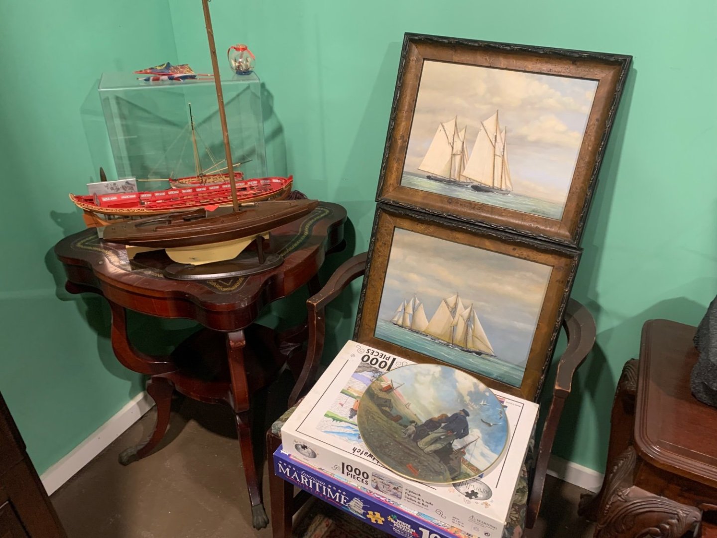
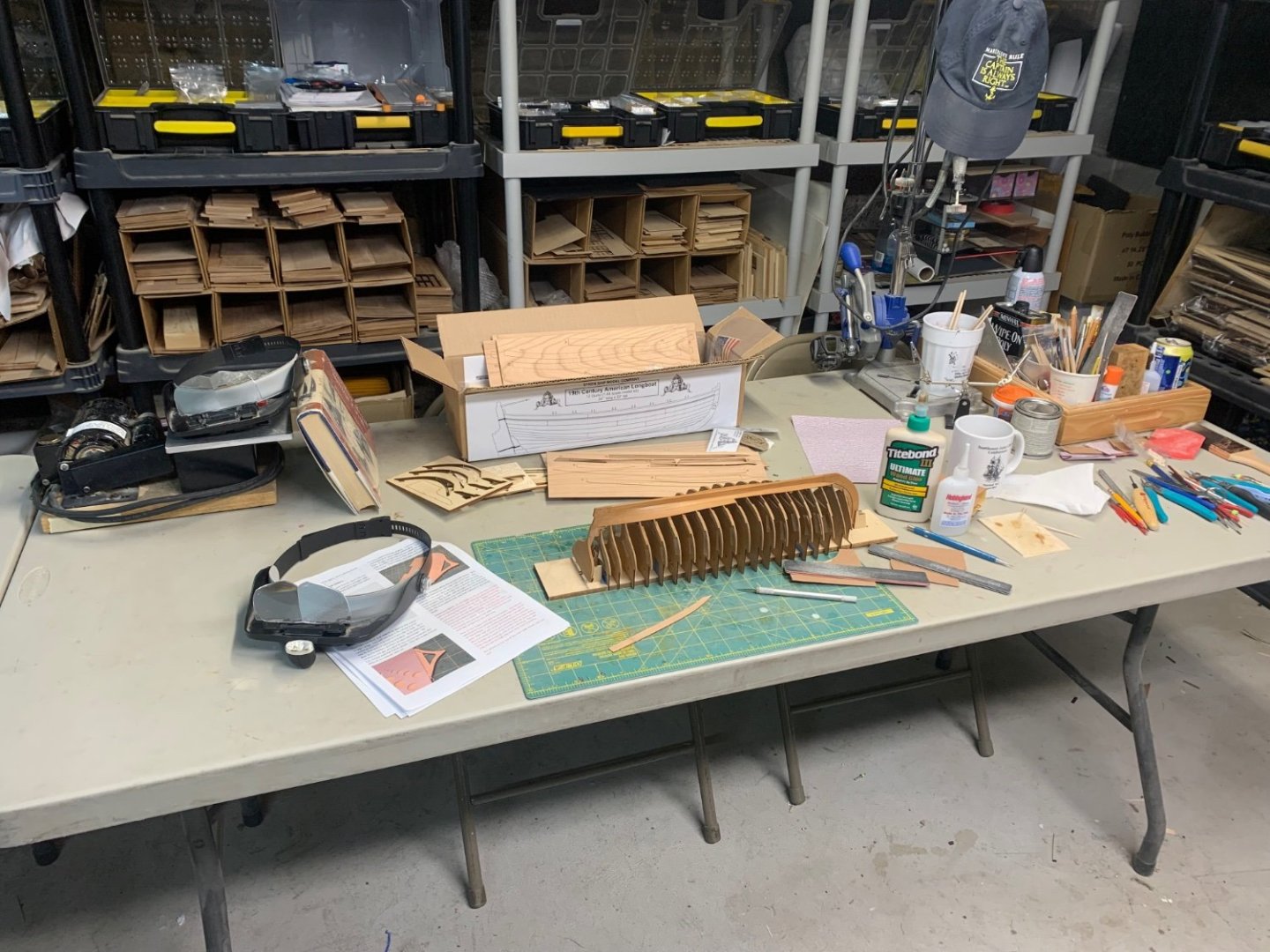
I just got back from the set where they will be filming. It was very interesting indeed. I brought about half of the ship models and tools needed to set up the house and workshop. I met some of the actors and an army of crew moving furniture around and staging the house. I have to be back there for the next few days as they get most of the heavy stuff done. Just a few of the items I am bringing. All this stuff is mine and also from my local NJ club members. The paintings will hang in a yacht club scene or two. Painted by my friend and club/msw member Richard Lane. Some of the models are his also along with Tom Ship Model (Tom Ruggiero) here on MSW and from local club. Some old tools and a kit stash etc. Old Nr Journals and books and an old Preac. My old ropewalks and serving machine. An old coffee mug from a Joint clubs conference,LOL and one of my old hats. You might notice my Longboat model is now American and the flag and name are changed for the movie…along with the Ed Harris character’s name on the side. I made the name plate in my laser cutter…all together a very interesting experience so far. The last photo shows how I will be setting up his workbench while he works on his longboat. There will be a junk scrap box and all around messy shop my own and many of yours.


-
Wonderful model and a wonderful cause....well done.
-
Funny! Yes it is quite the experience. The movie is called Riff Raff. Its a remake of an old movie. Should be fun. I will be setting up a garage workshop for them down to the sawdust on the floor. Filming has begun and I should be in the thick of it for a while. chuck
-
Thank you guys. Work will slow down for a while. I have been hired to help out on a feature film for the next couple of weeks. The lead actor is a ship modeler. I have been asked to help set up a believable ship model workshop and stage the home with my models along with others from my New Jersey club members. Its exciting and a once in a lifetime thing I just couldnt pass up. The lead character played by Ed Harris will be building my Medway Longboat kit in his workshop. How great is that…along with my tools and other things to dress up his garage workshop. I am going to help teach them how to fake it as a ship modeler. Starring Ed Harris, Dustin Hoffman, Jennifer Coolidge and Gabriel Union.
-
Thank you very much....I am hooked too. Chuck
-
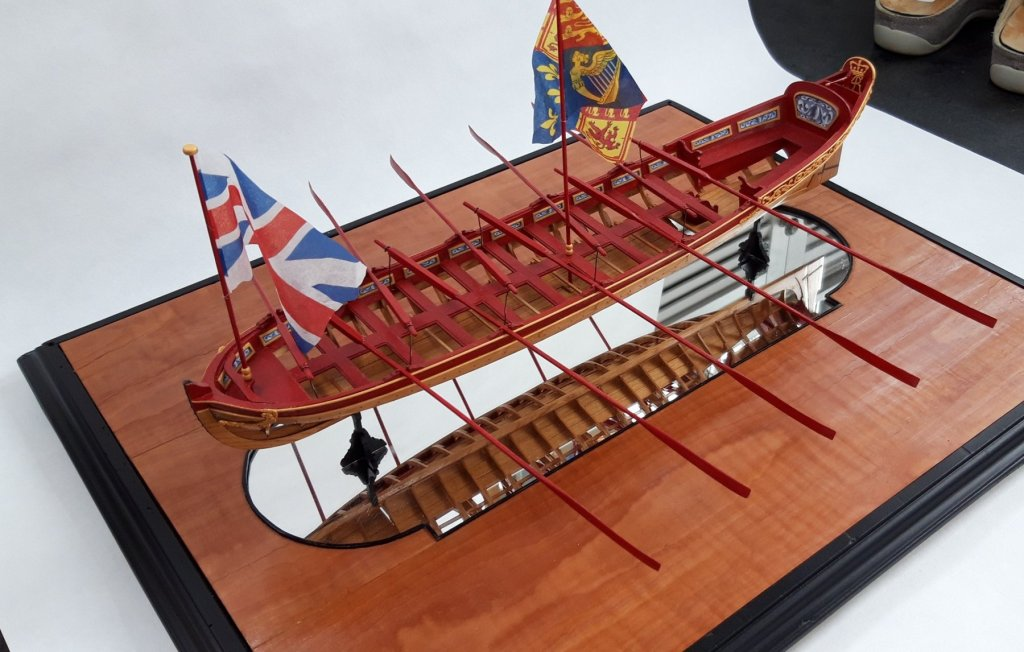
That is a beautiful model. If you can tackle that kit you will have no issues with any other. That is a first-class model.
- 217 replies
-
- 3
-
-
- medway longboat
- Syren Ship Model Company
- (and 1 more)
-
That is looking great. Well done. Onto the fun bit now.
-
That is looking very good indeed. Well done planking. That will be a fine looking model. Chuck
-
Thank you kindly for saying...
-
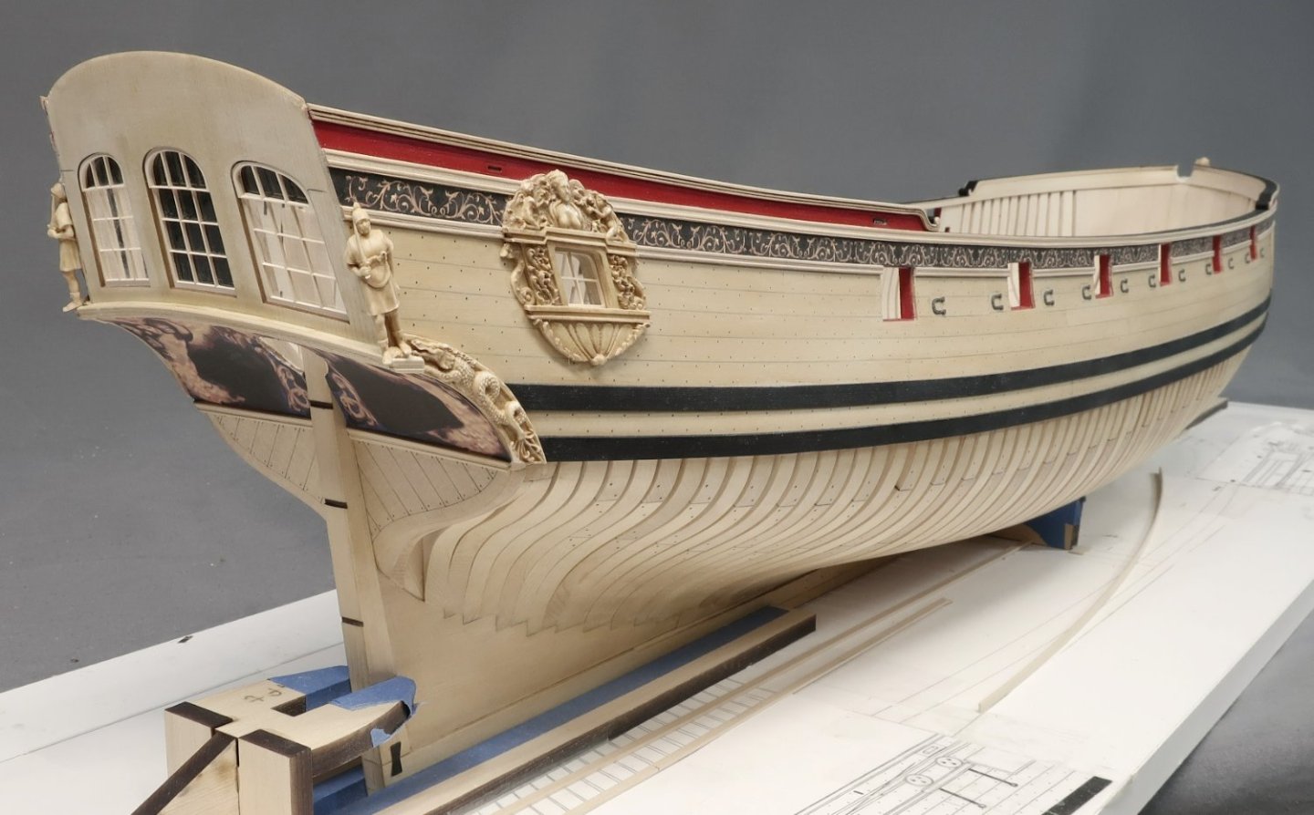
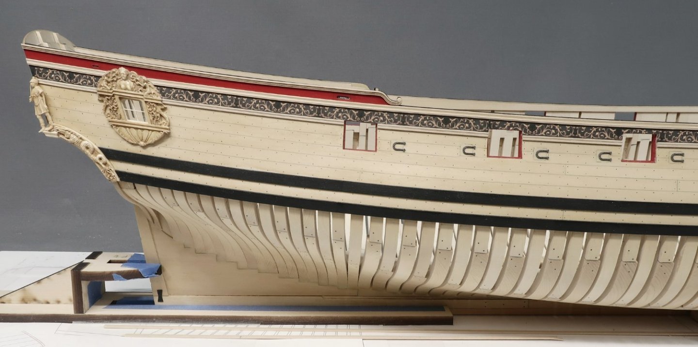
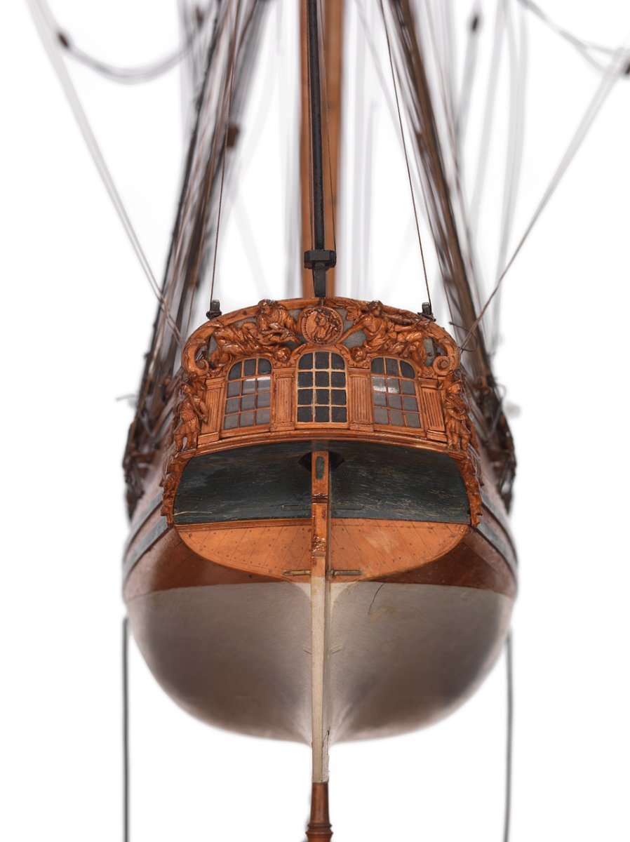
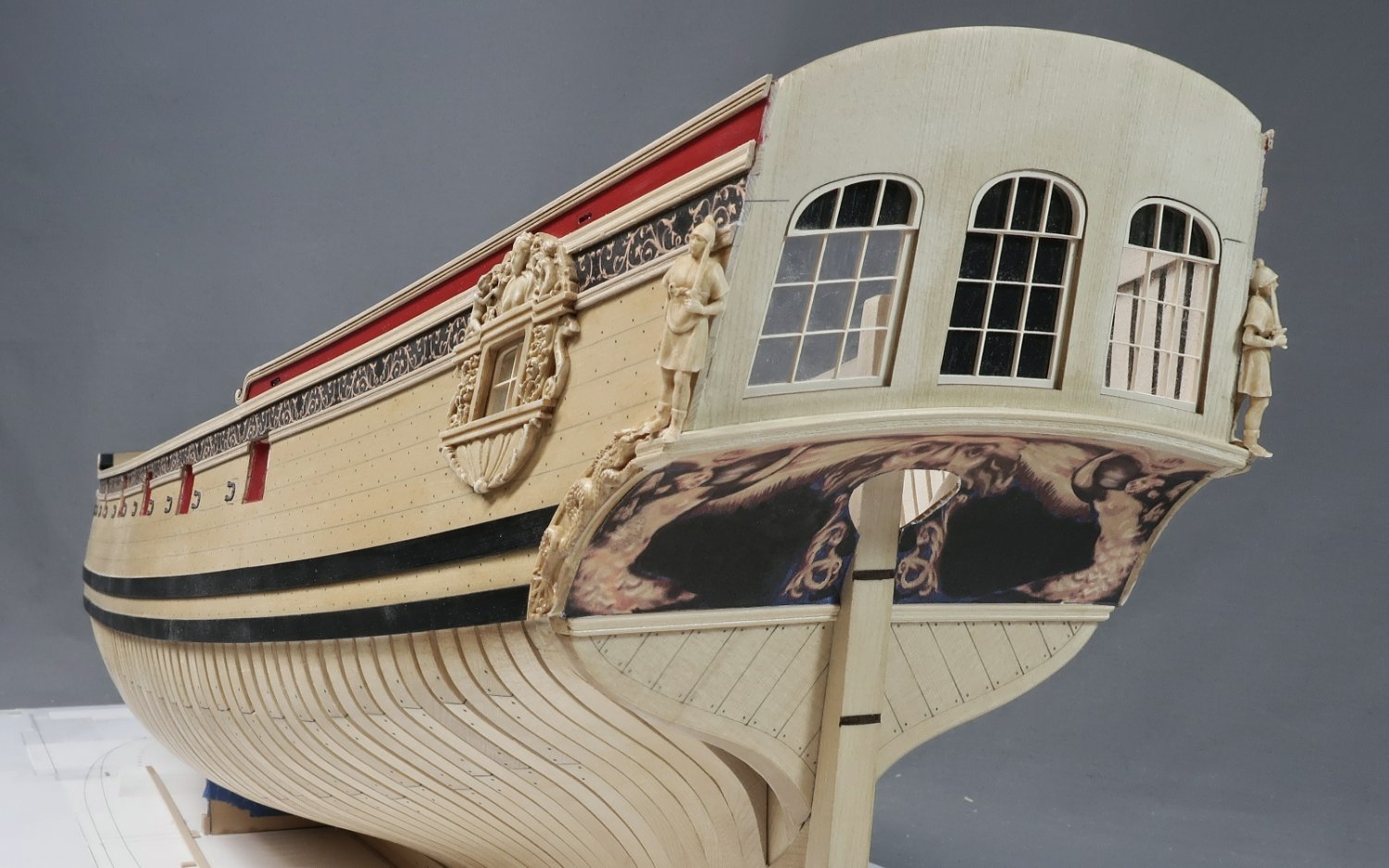
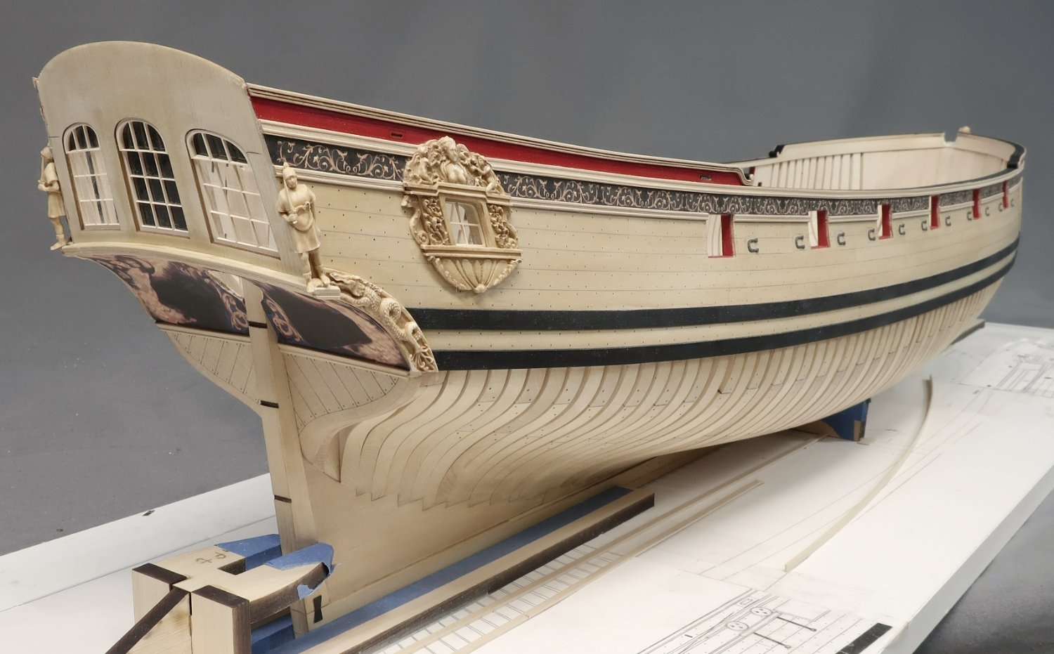
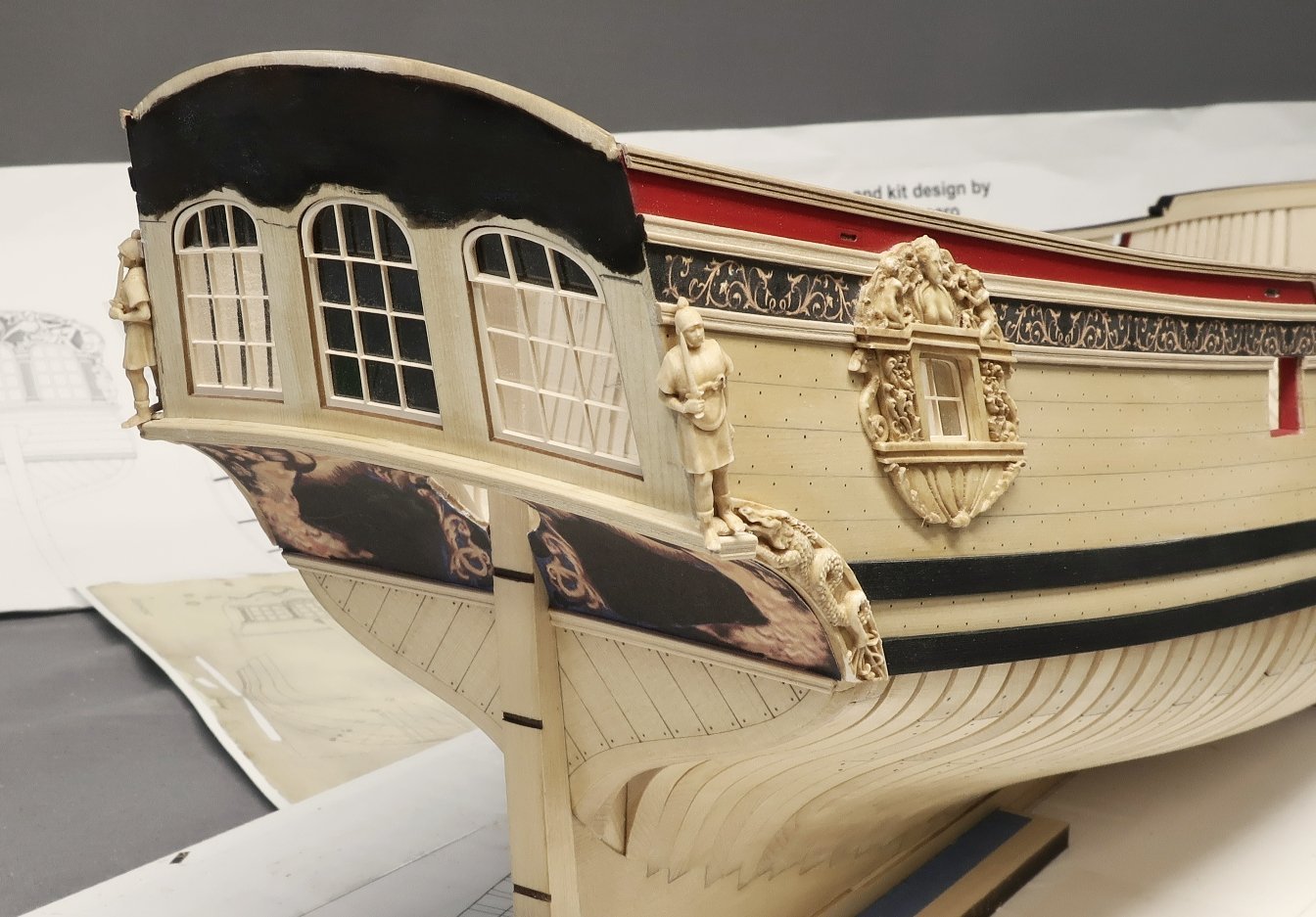
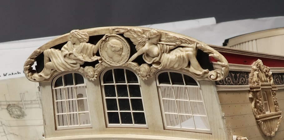
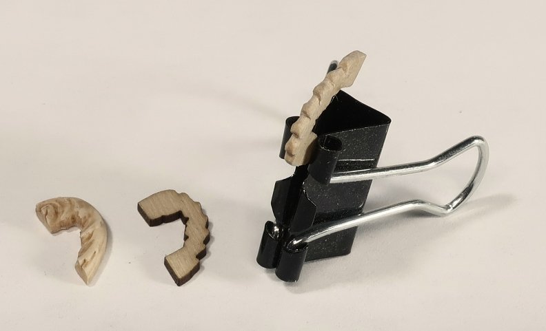
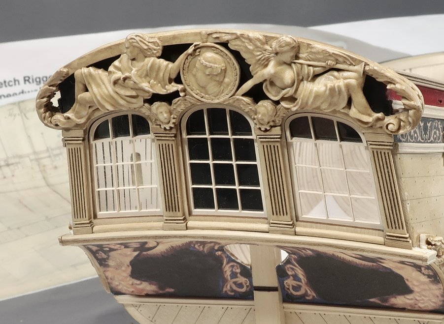
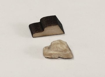
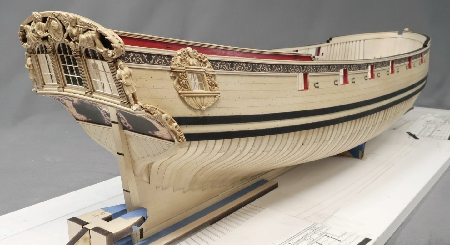
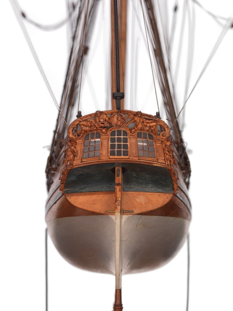
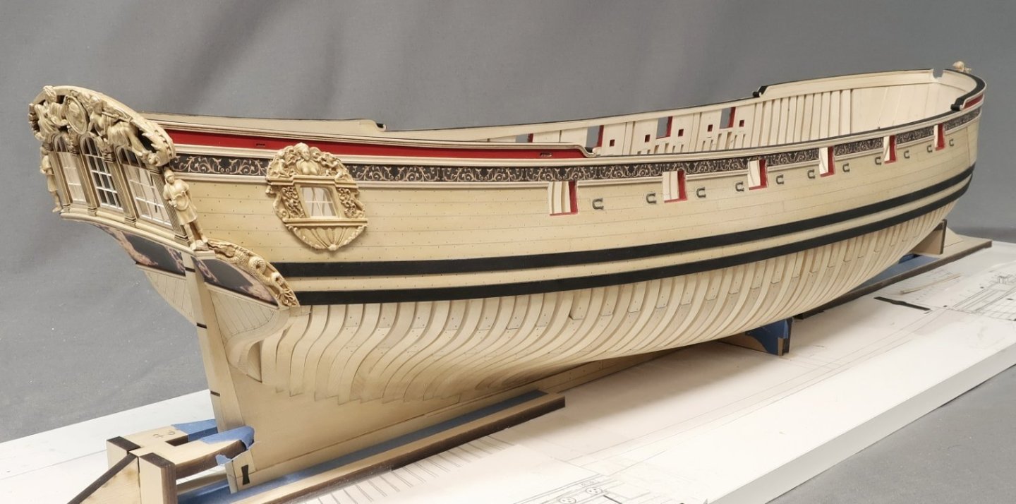
Finally finished up the stern details today. At least up to the point I would like to do them for this chapter. First up was to paint the top of the transom before adding the actual carvings. I didnt have to paint all the way to the upper edge. I didnt want a painted seam to show afterwards. I also marked the lower areas so I knew where to stop the painting as well. You cant tell in the photos but its not black at all. Its a very muted brown black and even gray. I didnt want it to be too stark a black. I also dusted some blue on there as well. So much for my photo skills, LOL. The two figures (port and starboard) were removed as they wont be added till last in this series of steps. Then the actual carved transom was glued into position. Once again this was after some initial cleanup and staining to make it match the wood color. Old masters gel stain (fruitwood) was used once again. With the transom carving secure it was time to focus on the forward side of the carving. Basically the thickness of the carved transom is thicker port and starboard. Where it hangs over on both sides. There is a little carved detail in the center of this as well which can be seen on the contemporary model. My solution was to build up this area with two layers. The first middle layer is laser cut in boxwood. This layer was cleaned up of it laser char and then shaped a bit with some sandpaper and files. The edges were rounded off and I just had some fun with it. You can see my example being held in the clamp. You guys can do as much as you like with this piece. Photo is below. Then the most forward layer will be glued on as well. This is a resin casting. When gluing them on you must finesse them a bit. Meaning you may have to trim some of the hull molding etc. You can fill any cracks or seams with wood filler and generally speaking try to blend them all together. The photo below shows these two layers on the model. They were glued to the forward side of the transom. Next up was to add the columns. This is pretty straight forward. All of these pieces are laser cut for you. The tops and bottoms of the columns are 1/16" thick. They were cleaned of laser char and filed to suit. Then glued on the transom. The long fluted columns are thinner but laser cut as well. The laser char sanded from these and the each column was sanded to length for a tight fit between the tops and bottoms we just added. This takes a while to do but isnt difficult. You may also notice some molding at the base of each window. They are between the columns bases. These are laser cut too. Just remove the char and round off the top edge like a quarter round. Then glue them in. Lastly we can put those two standing figures back where they belong. But before you do...there are tiny laser cut bases made for them. These bases or the floor...rock...the ground...whatever you would like to call them need to be shaped. They are shaped like a little step. I did this rather than incorporate them into the casting. Everybody's model is slightly different. You can customize this base so your figure fits perfect on your model. See the photo... Just sand it free of char and file some bumps and grooves into it. Mine are hardly noticeable in the photo but they are there. Make it look like a stone or rock base. Using this keeps the nice run of the molding that wraps around the stern while covering the seams between all those layers we created. It covers up where the figures will stand while creating the correct angle for the figure to match the transom. It will be hardly visible. Shape yours to suit. Here the figure is glued in place but not until after the tiny base was glued in position first. You can see the figure stepping on the small rock carved base. This pretty much finishes up the stern to the point where I want to be in this chapter. Its for the most part complete except for some very small features we add much much later. I think it came out rather nice considering this is a kit. But my goal was of course not to make it look kit-like at all. The contemporary model...
-
Looking fantastic Mike...
-
She knows....
-
I can not explain how devastated I am to be announcing this. My dear and close friend Jim Byrnes has passed away way too soon. Many have you know and have met Jim. He was a fantastic guy and true original. Many of you own his tools which are second to none in the hobby. I have been speaking with his wife Donna who many of you also know. Jim was diagnosed with ALS in February. ALS is a nasty disease and there is no cure. Jim had a particularly aggressive type of ALS and he passed away last month in October. He was just 64 years old. This news will be devastating to many...but Donna has asked if everyone would have patience and give here and their family time to grieve. As you might expect, the business will continue to be shut down, but will reopen at some time in the near future. Donna will continue supporting the hobby and their customers when the time is right. But please have patience and allow the family to grieve at this sad time. Donna will let me know when the shop will reopen. I will make an announcement at that time. I am so devastated by this...I just spoke to him not too long ago and it breaks my heart. His obituary is below. Jim is survived by his wife, Donna; son, James William (Krystal) and grandchildren Julian and Sloane; brother, Peter (Cindy) Byrnes and sisters, Mary (James) Hayman, Catherine Byrnes, Veronica Byrnes and Elaine Byrnes (Robert Campbell); brother-in-law, Eddie (Marcia) Grissom; brother-in-law, Frank Marzovilla, and many cherished nieces and nephews. Not to be forgotten is his beloved English Springer Spaniel, Becky, who is waiting every day for him to come home to her! He was preceded in death by his parents, James and Lorraine Byrnes; brother, Robert Byrnes; nephew, Michael Byrnes; brother-in-law, Pete Stuffer; and mother-in-law, Opal Grissom. Along with restoring vintage cars, from a very young age Jim had a true passion for model ship-building. For many years he had done extensive research on the U.S.S. Constitution and was in the final phase of completing his scratch build of the Constitution as it was originally launched in 1797. Following a career of working with Defense contract companies, Jim worked many years with and became a partner with Conceptual Engineering in Sanford FL. In 2002 Jim and Donna formed Model Machines LLC. Jim designed and developed small modeler’s machines that are now purchased worldwide and used in many high school and college machine shops and in museums for their restorations. There have been numerous reviews and articles written about Jim which were published in various modelers’ magazines. Modelers using Jim’s machines range from ship, railroad, doll houses, doll house furniture, pen turners, segmented bowls and architects. In recent years guitar, harp and violin makers were added to this list. Jim was a remarkable craftsman and had many more machines in development stage for modelers. He was always ready to help and mentor others, many of whom soon became his very close friends. Jim was also a member of the Nautical Research Guild and attended conferences throughout the U.S. for 20 years, developing many close friendships within this organization. Jim was a humble, quiet man who was deeply loved and will be missed by so many. Our hearts, as a family, are broken. Thru this profound loss, if we can ask one thing from this place of despair, it would be to embrace your loved ones every chance you get.
- 44 replies
-
- 59
-

-
-
Yes ....I really wish they had chosen a much simpler and smaller ship for a venture into POF. Then maybe they wouldnt have had to skimp on the kit-like details. Its shame but I give them an "A" for effort. It pains me to say this...but the POF stuff coming out of Asia is about ten times better and about the same price points. Yes most are are copies and outright thefts....BUT I can understand why folks actually buy them. There arent many other options. But the Victory as the first one!!! Maybe a one decker or two decker might have been better.
-
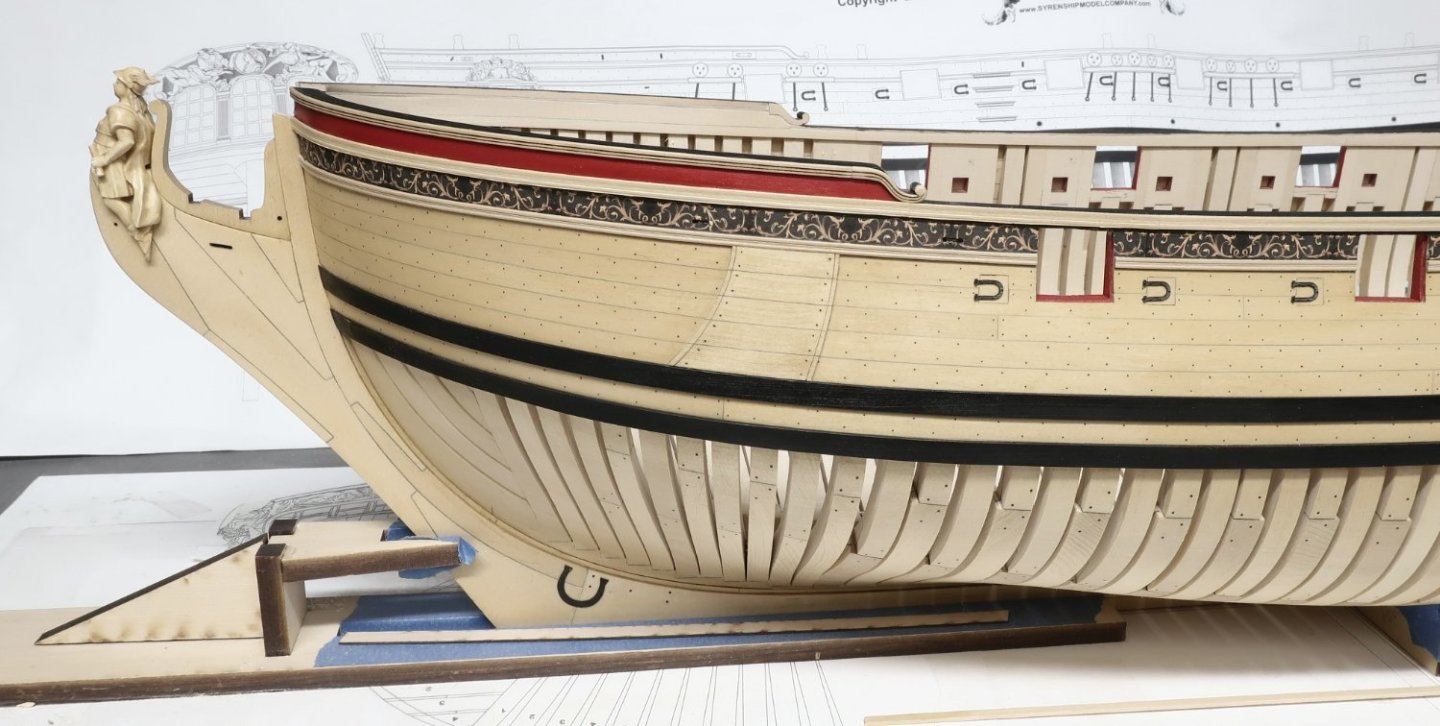
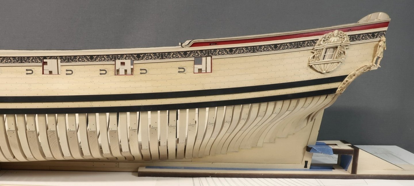
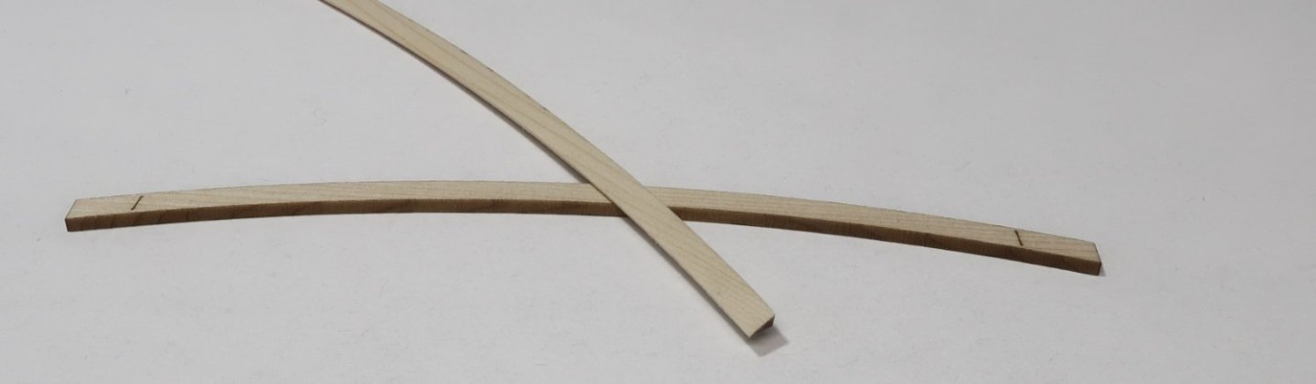
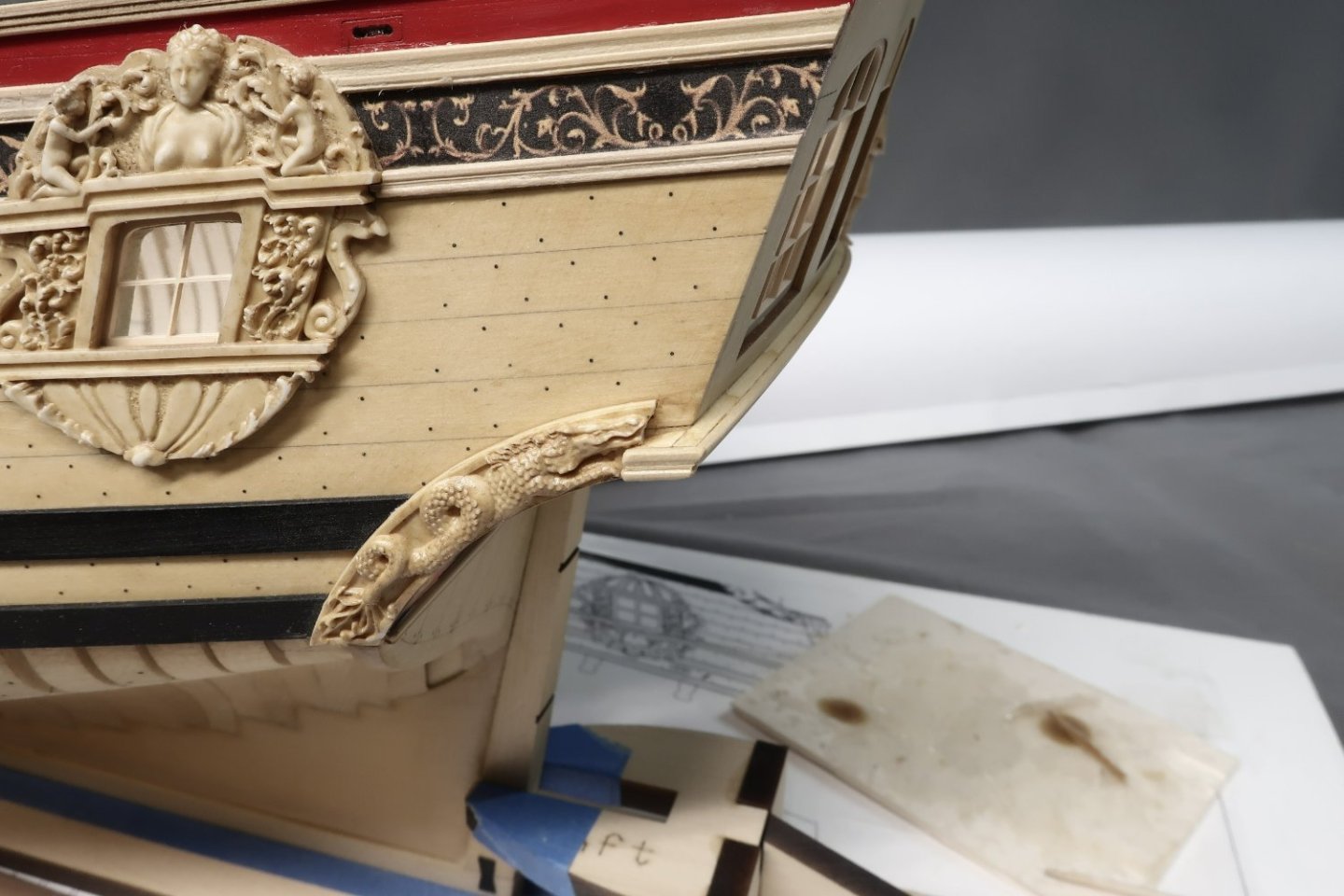
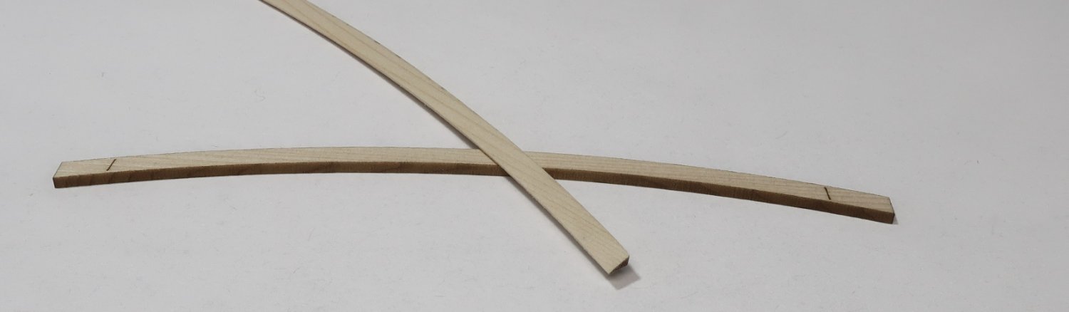
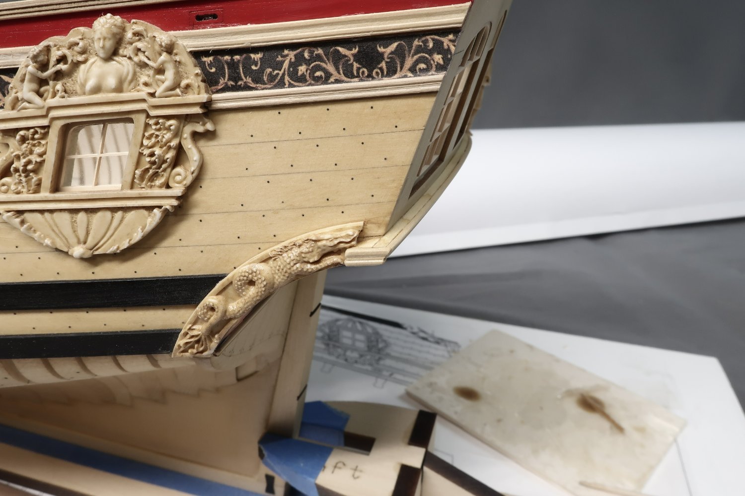
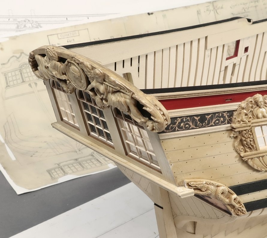
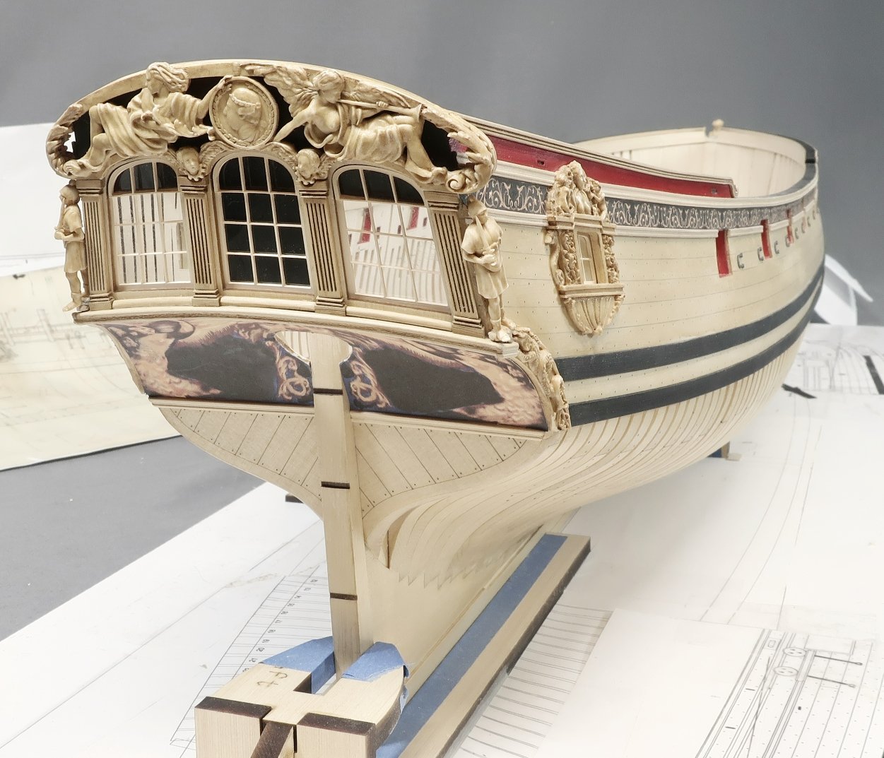
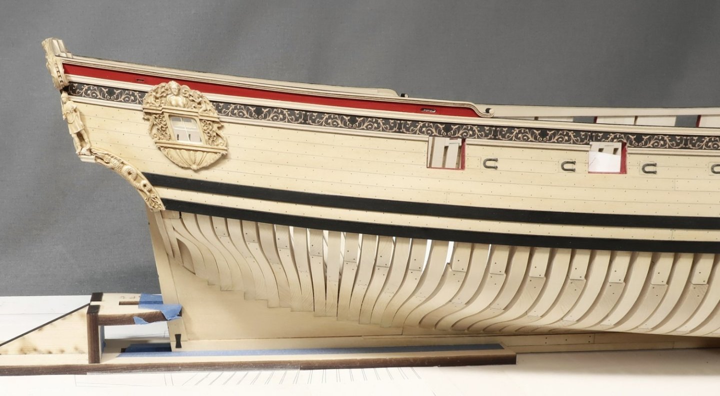
Just a little bit of work today to start chapter 4. I actually did forget to add something for chapter 3 so I just made it the first thing in this new chapter. That was the anchor lining. Its pretty straight forward. Each strake of the anchor lining is laser cut although it may not line up perfectly with everyone's planking on individual models. You guys may make some planks narrower or taper them less up there. But its better to have them I suppose and if folks have to they can easily make them from scratch. Then starts the stern details... First up was to scratch some molding for the lowest one just above the square tuck. You guys have done this before. 1/8" x 1/32" strip of boxwood scraped. Then the frieze was cut out and glued on. The darker one of course to match the friezes on the side of the hull. Then the upper molding above the frieze was added. It was done in two layer. The first is laser cut for you on a curve to match the curve of the transom. There are registration marks to help center it etched onto the FORWARD side of the molding. This is the side that gets glued to the transom. The AFT side of this strip need to be sanded with an angle along its entire length. This helps establish the correct angles of the second layer which we will add later. The laser cut piece on the bottom is a non sanded example just to show the laser etched lines that help you center it. The ends will hang over on both sides of the hull quite a bit. That is by design. But you can see the other example on top which has been sanded along its entire length on an angle, basically making it triangular in profile or wedge shaped. This can be glued on the model once completed. Thats when you can scrape another length of 1/8" x 1/16" boxwood strip which can be glued on top of it. Its just a cheat to help establish the correct angles of this complex piece of molding. Then the sides are completed and trimmed which is a boring long process I wont bother posting here...bit in the end you get this below. You can see how it extends beyond the side to create a little platform. This is for the standing figure. Its not time to glue these figures on permanently yet....but I did want to do a test to check its size and fit and placement. I removed them right after. Note how the figures follow the angle of the transom when viewed from the side of the hull. The figure was designed to look like it was stepping forward and leaning. This is important for the look of the model. They face almost outward from the side so the front of the torso almost faces port and starboard. Although there is a slight turn aft as well. One foot also slightly hangs over the molding which is correct but maybe not this much once I actually glue them on permanently. Thats it for now but a little painting is next up so I can continue work on the stern. There are the typical columns and such as well as the carvings above the windows. Chuck