Chuck
-
Posts
9,704 -
Joined
-
Last visited
Content Type
Profiles
Forums
Gallery
Events
Everything posted by Chuck
-
 That is a beautiful model. If you can tackle that kit you will have no issues with any other. That is a first-class model.
- 217 replies
-
- 3
-

-
- medway longboat
- Syren Ship Model Company
- (and 1 more)
-
That is looking great. Well done. Onto the fun bit now.
-
That is looking very good indeed. Well done planking. That will be a fine looking model. Chuck
-
Thank you kindly for saying...
-
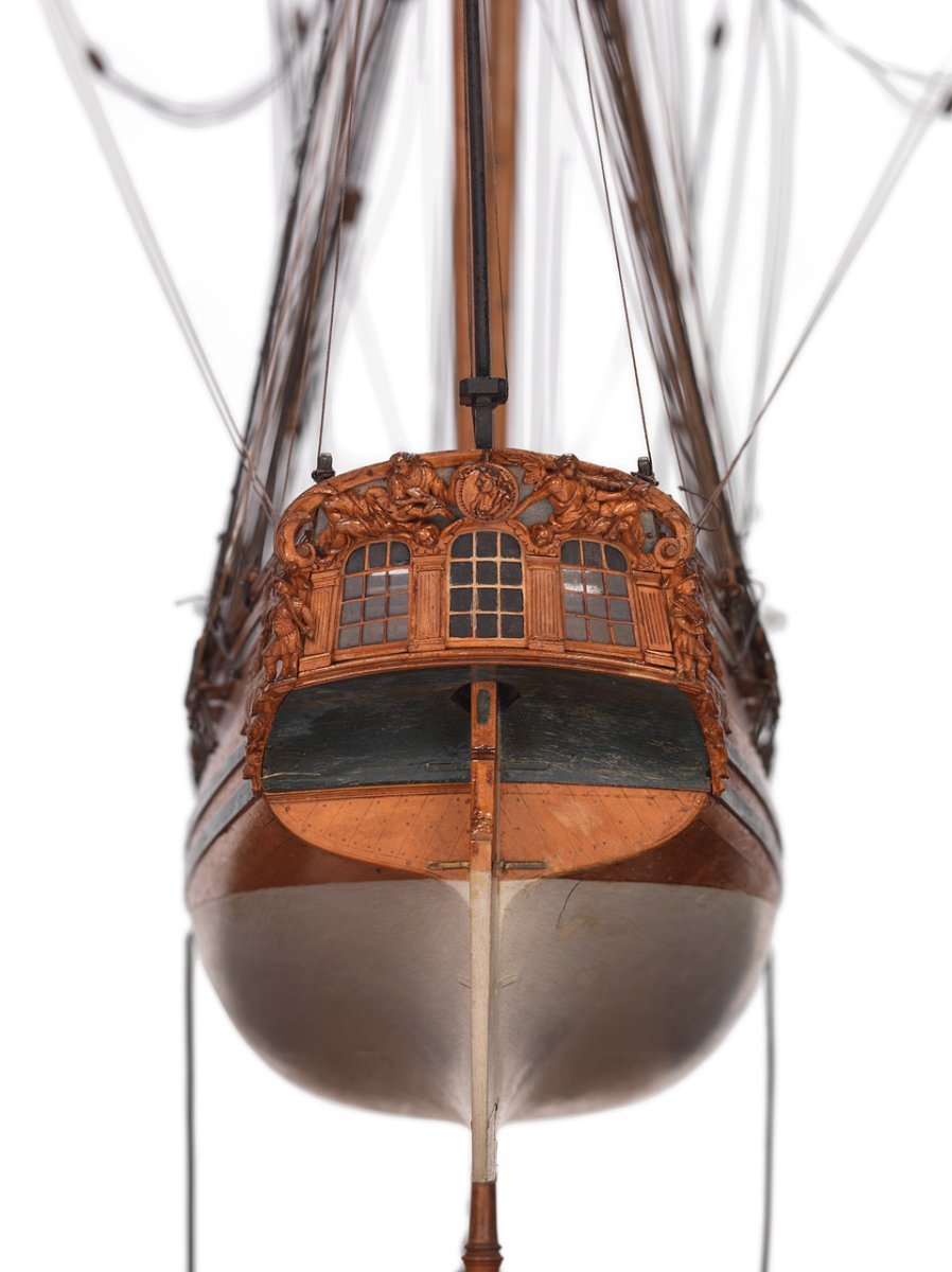
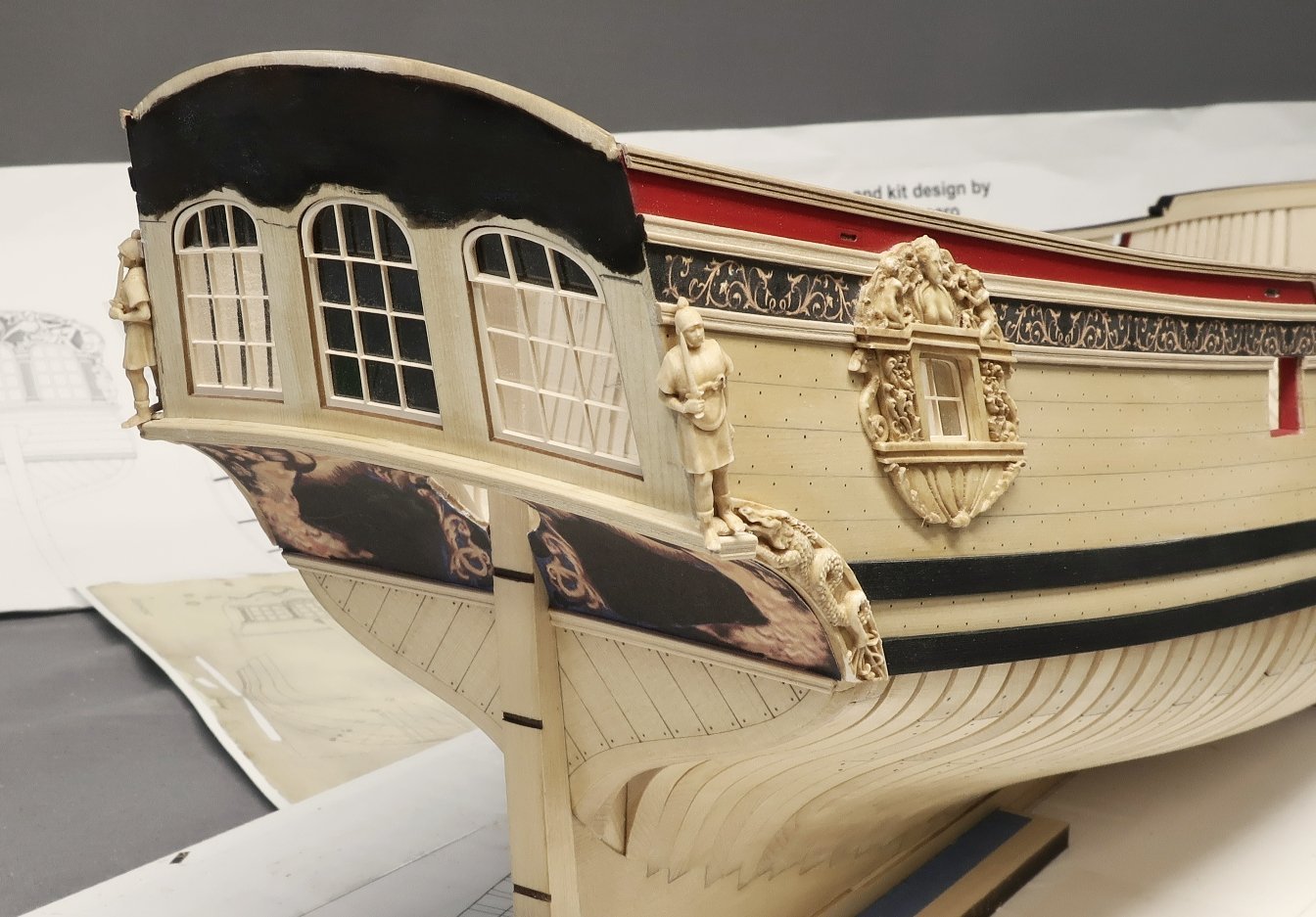
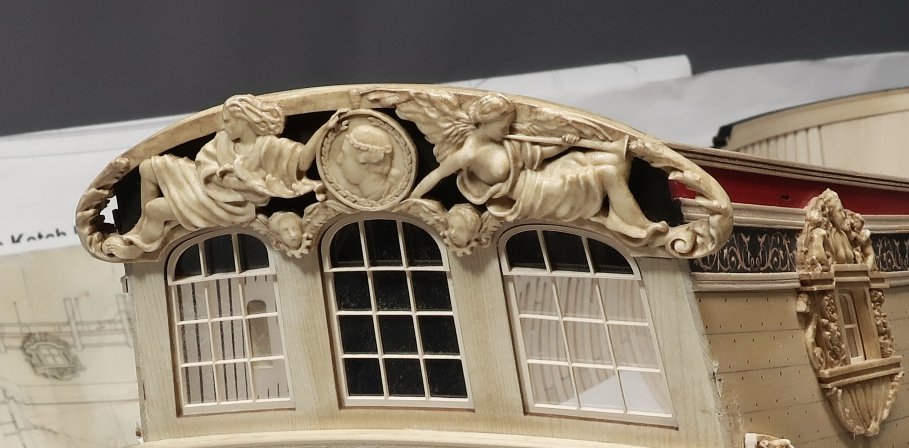
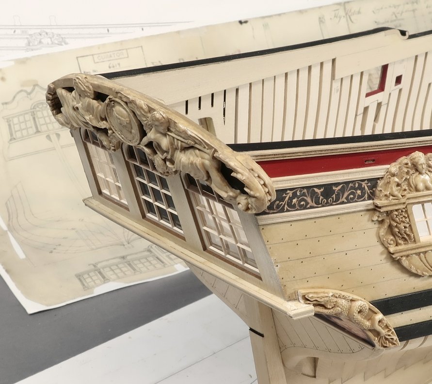
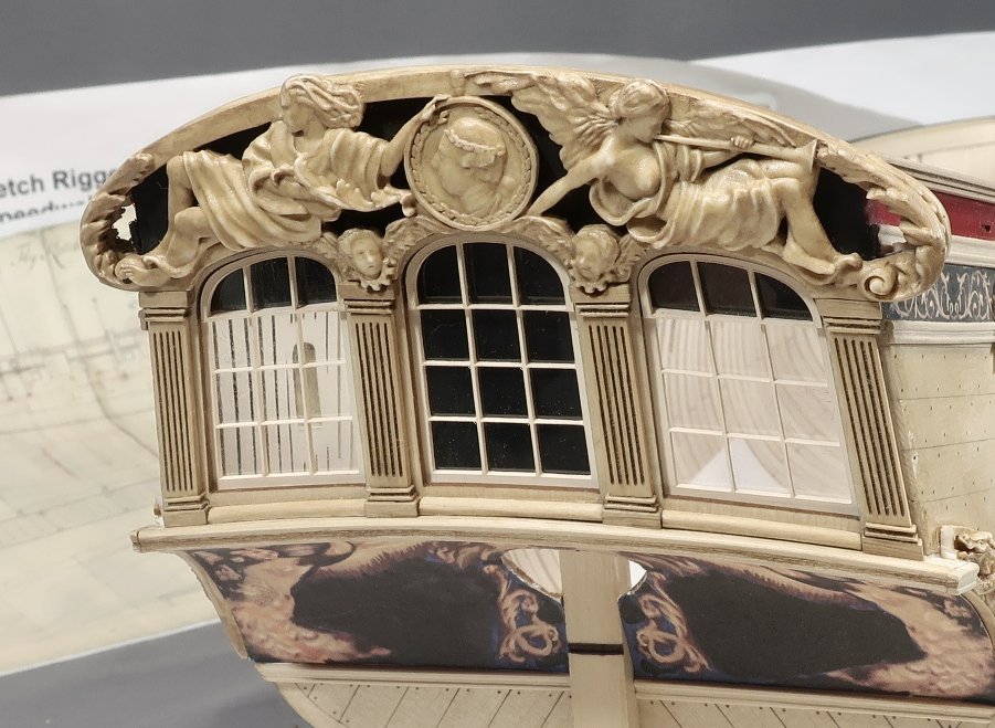
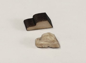
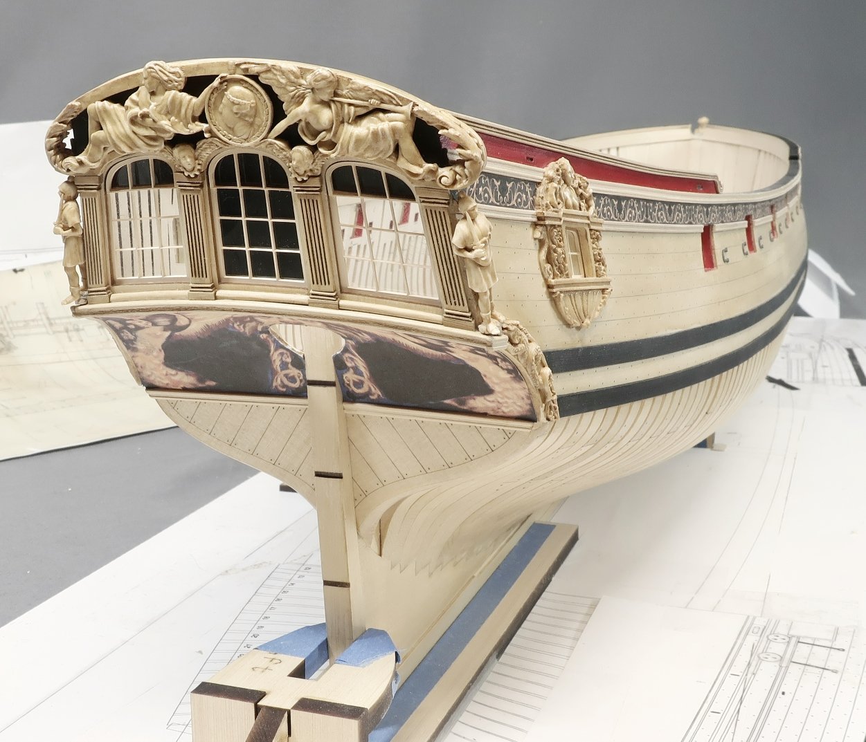
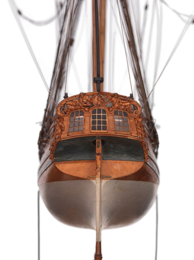
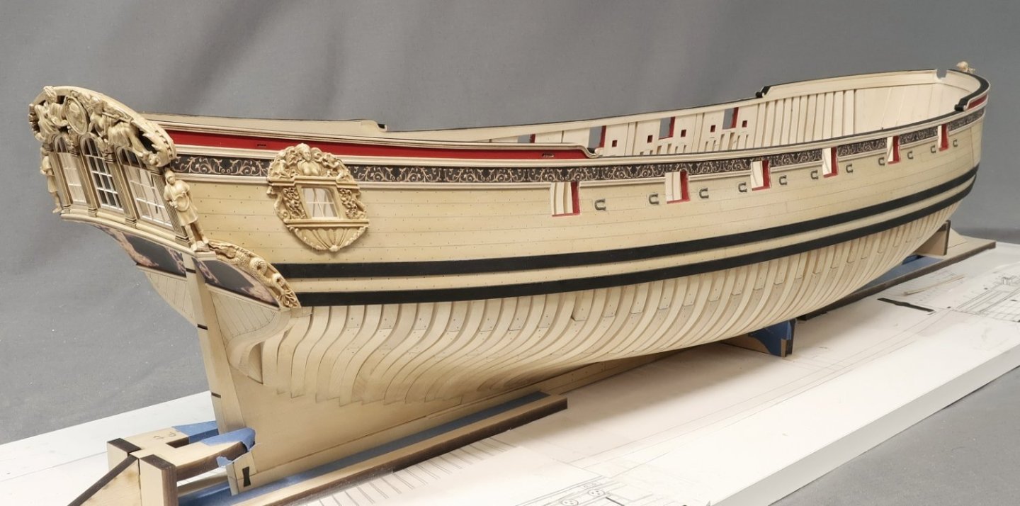
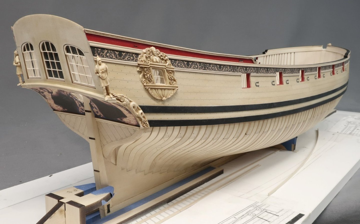
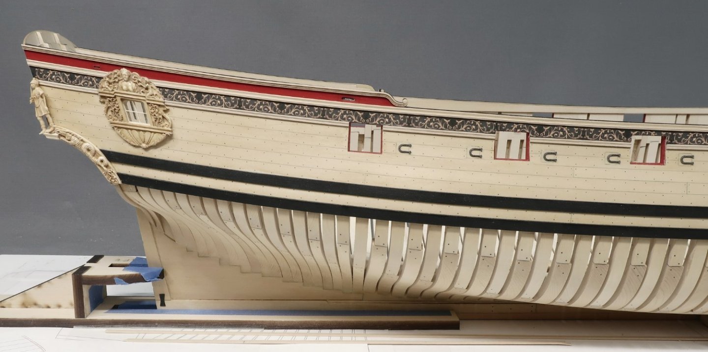
Finally finished up the stern details today. At least up to the point I would like to do them for this chapter. First up was to paint the top of the transom before adding the actual carvings. I didnt have to paint all the way to the upper edge. I didnt want a painted seam to show afterwards. I also marked the lower areas so I knew where to stop the painting as well. You cant tell in the photos but its not black at all. Its a very muted brown black and even gray. I didnt want it to be too stark a black. I also dusted some blue on there as well. So much for my photo skills, LOL. The two figures (port and starboard) were removed as they wont be added till last in this series of steps. Then the actual carved transom was glued into position. Once again this was after some initial cleanup and staining to make it match the wood color. Old masters gel stain (fruitwood) was used once again. With the transom carving secure it was time to focus on the forward side of the carving. Basically the thickness of the carved transom is thicker port and starboard. Where it hangs over on both sides. There is a little carved detail in the center of this as well which can be seen on the contemporary model. My solution was to build up this area with two layers. The first middle layer is laser cut in boxwood. This layer was cleaned up of it laser char and then shaped a bit with some sandpaper and files. The edges were rounded off and I just had some fun with it. You can see my example being held in the clamp. You guys can do as much as you like with this piece. Photo is below. Then the most forward layer will be glued on as well. This is a resin casting. When gluing them on you must finesse them a bit. Meaning you may have to trim some of the hull molding etc. You can fill any cracks or seams with wood filler and generally speaking try to blend them all together. The photo below shows these two layers on the model. They were glued to the forward side of the transom. Next up was to add the columns. This is pretty straight forward. All of these pieces are laser cut for you. The tops and bottoms of the columns are 1/16" thick. They were cleaned of laser char and filed to suit. Then glued on the transom. The long fluted columns are thinner but laser cut as well. The laser char sanded from these and the each column was sanded to length for a tight fit between the tops and bottoms we just added. This takes a while to do but isnt difficult. You may also notice some molding at the base of each window. They are between the columns bases. These are laser cut too. Just remove the char and round off the top edge like a quarter round. Then glue them in. Lastly we can put those two standing figures back where they belong. But before you do...there are tiny laser cut bases made for them. These bases or the floor...rock...the ground...whatever you would like to call them need to be shaped. They are shaped like a little step. I did this rather than incorporate them into the casting. Everybody's model is slightly different. You can customize this base so your figure fits perfect on your model. See the photo... Just sand it free of char and file some bumps and grooves into it. Mine are hardly noticeable in the photo but they are there. Make it look like a stone or rock base. Using this keeps the nice run of the molding that wraps around the stern while covering the seams between all those layers we created. It covers up where the figures will stand while creating the correct angle for the figure to match the transom. It will be hardly visible. Shape yours to suit. Here the figure is glued in place but not until after the tiny base was glued in position first. You can see the figure stepping on the small rock carved base. This pretty much finishes up the stern to the point where I want to be in this chapter. Its for the most part complete except for some very small features we add much much later. I think it came out rather nice considering this is a kit. But my goal was of course not to make it look kit-like at all. The contemporary model...
-
Looking fantastic Mike...
-
She knows....
-
I can not explain how devastated I am to be announcing this. My dear and close friend Jim Byrnes has passed away way too soon. Many have you know and have met Jim. He was a fantastic guy and true original. Many of you own his tools which are second to none in the hobby. I have been speaking with his wife Donna who many of you also know. Jim was diagnosed with ALS in February. ALS is a nasty disease and there is no cure. Jim had a particularly aggressive type of ALS and he passed away last month in October. He was just 64 years old. This news will be devastating to many...but Donna has asked if everyone would have patience and give here and their family time to grieve. As you might expect, the business will continue to be shut down, but will reopen at some time in the near future. Donna will continue supporting the hobby and their customers when the time is right. But please have patience and allow the family to grieve at this sad time. Donna will let me know when the shop will reopen. I will make an announcement at that time. I am so devastated by this...I just spoke to him not too long ago and it breaks my heart. His obituary is below. Jim is survived by his wife, Donna; son, James William (Krystal) and grandchildren Julian and Sloane; brother, Peter (Cindy) Byrnes and sisters, Mary (James) Hayman, Catherine Byrnes, Veronica Byrnes and Elaine Byrnes (Robert Campbell); brother-in-law, Eddie (Marcia) Grissom; brother-in-law, Frank Marzovilla, and many cherished nieces and nephews. Not to be forgotten is his beloved English Springer Spaniel, Becky, who is waiting every day for him to come home to her! He was preceded in death by his parents, James and Lorraine Byrnes; brother, Robert Byrnes; nephew, Michael Byrnes; brother-in-law, Pete Stuffer; and mother-in-law, Opal Grissom. Along with restoring vintage cars, from a very young age Jim had a true passion for model ship-building. For many years he had done extensive research on the U.S.S. Constitution and was in the final phase of completing his scratch build of the Constitution as it was originally launched in 1797. Following a career of working with Defense contract companies, Jim worked many years with and became a partner with Conceptual Engineering in Sanford FL. In 2002 Jim and Donna formed Model Machines LLC. Jim designed and developed small modeler’s machines that are now purchased worldwide and used in many high school and college machine shops and in museums for their restorations. There have been numerous reviews and articles written about Jim which were published in various modelers’ magazines. Modelers using Jim’s machines range from ship, railroad, doll houses, doll house furniture, pen turners, segmented bowls and architects. In recent years guitar, harp and violin makers were added to this list. Jim was a remarkable craftsman and had many more machines in development stage for modelers. He was always ready to help and mentor others, many of whom soon became his very close friends. Jim was also a member of the Nautical Research Guild and attended conferences throughout the U.S. for 20 years, developing many close friendships within this organization. Jim was a humble, quiet man who was deeply loved and will be missed by so many. Our hearts, as a family, are broken. Thru this profound loss, if we can ask one thing from this place of despair, it would be to embrace your loved ones every chance you get.
- 44 replies
-
- 59
-

-
-
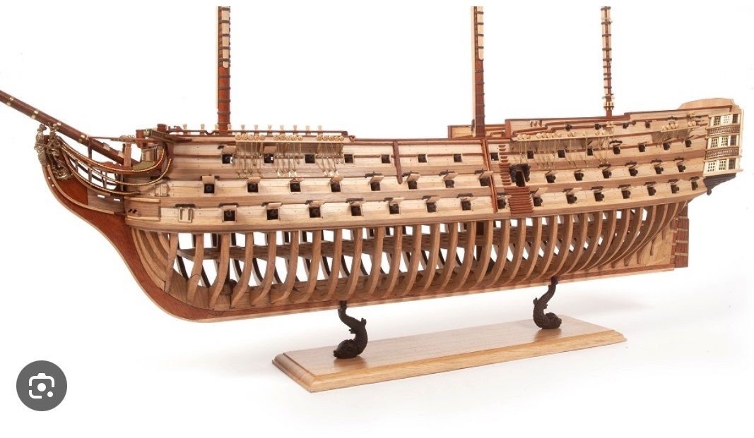
Yes ....I really wish they had chosen a much simpler and smaller ship for a venture into POF. Then maybe they wouldnt have had to skimp on the kit-like details. Its shame but I give them an "A" for effort. It pains me to say this...but the POF stuff coming out of Asia is about ten times better and about the same price points. Yes most are are copies and outright thefts....BUT I can understand why folks actually buy them. There arent many other options. But the Victory as the first one!!! Maybe a one decker or two decker might have been better.
-
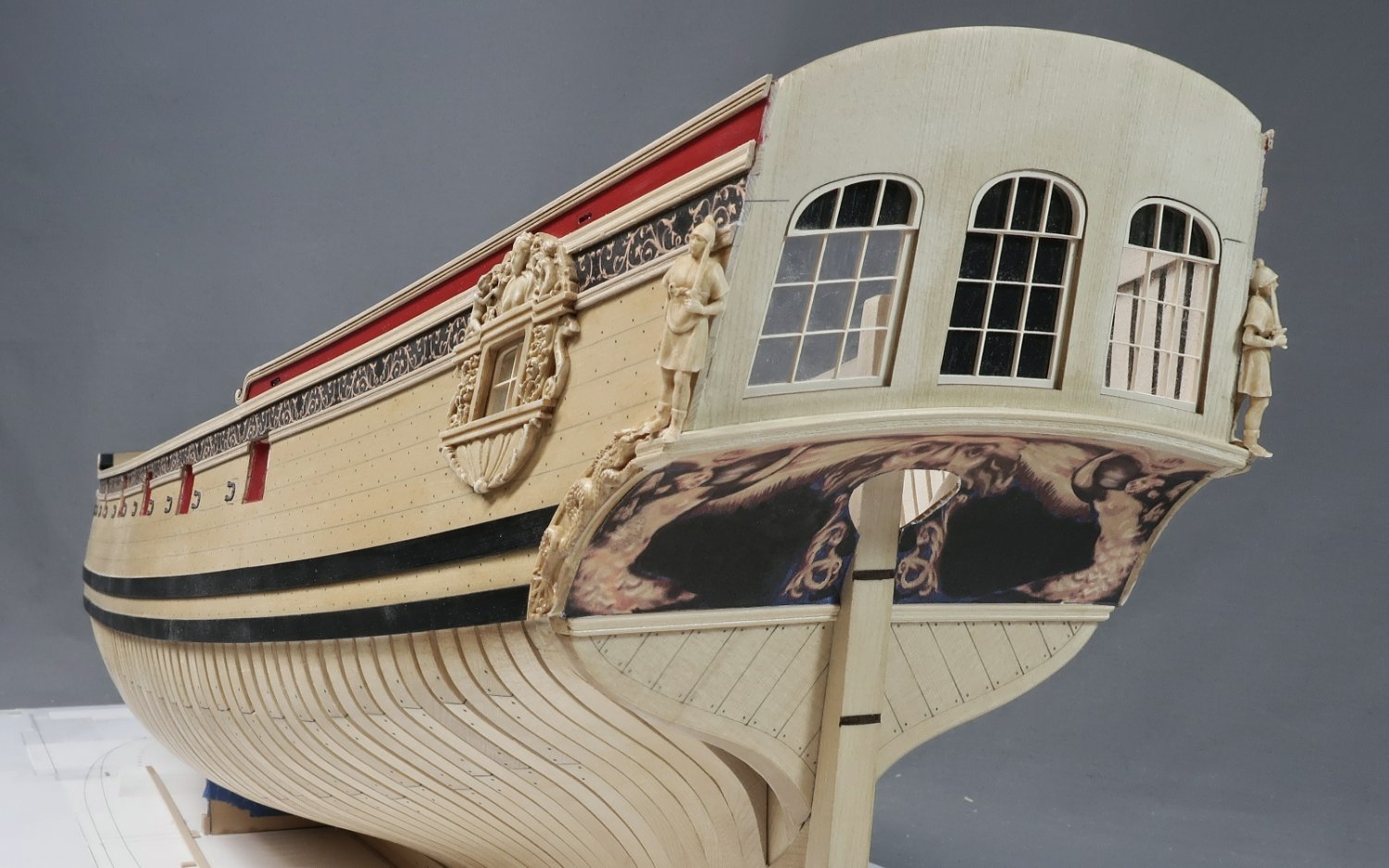
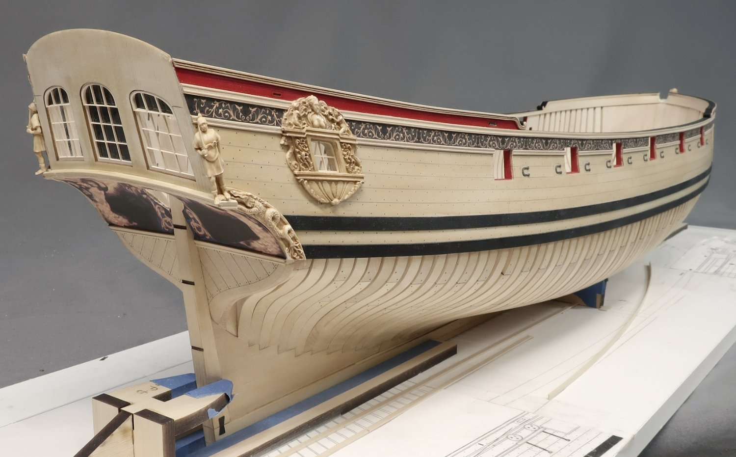
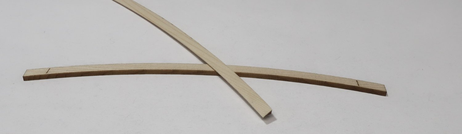
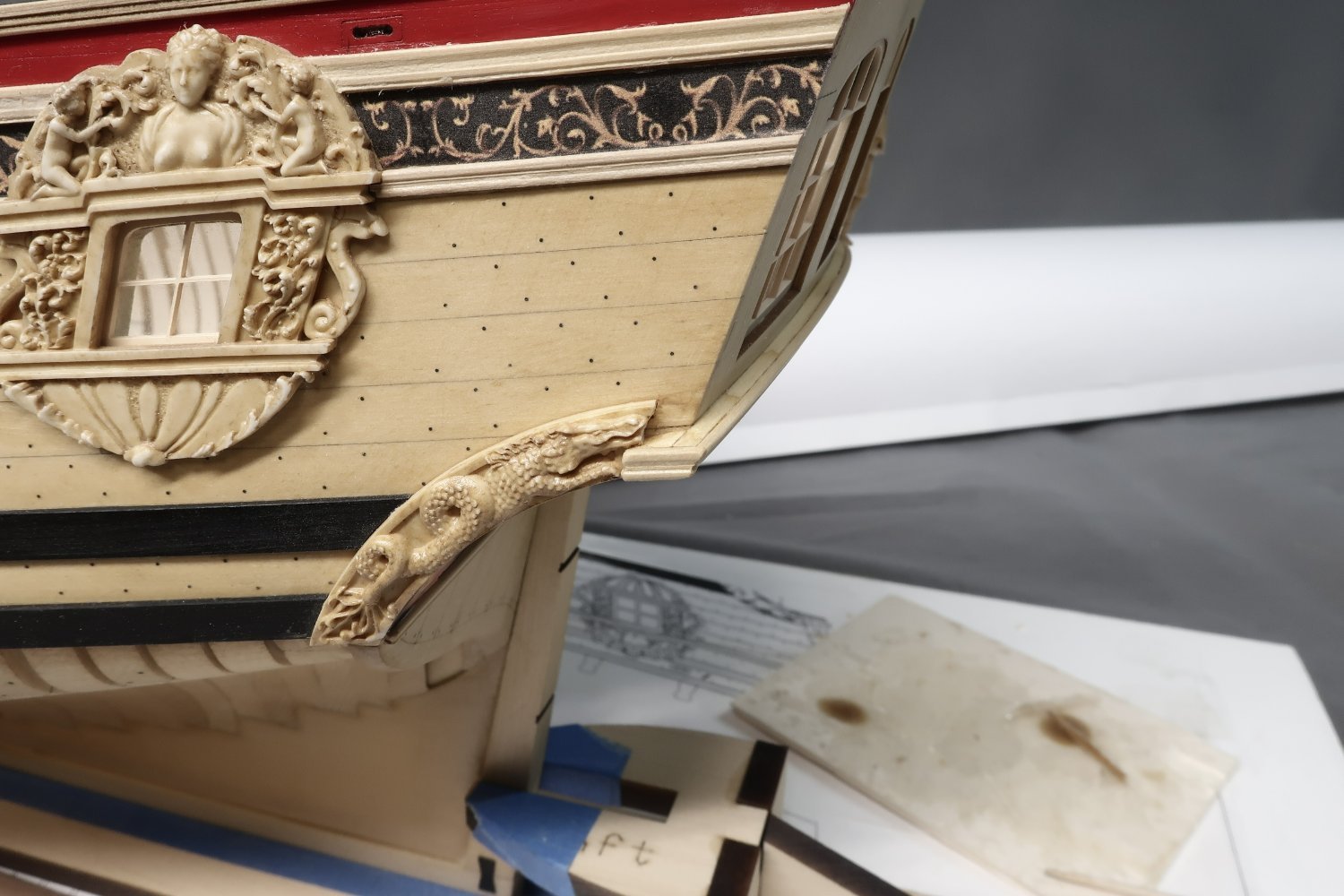
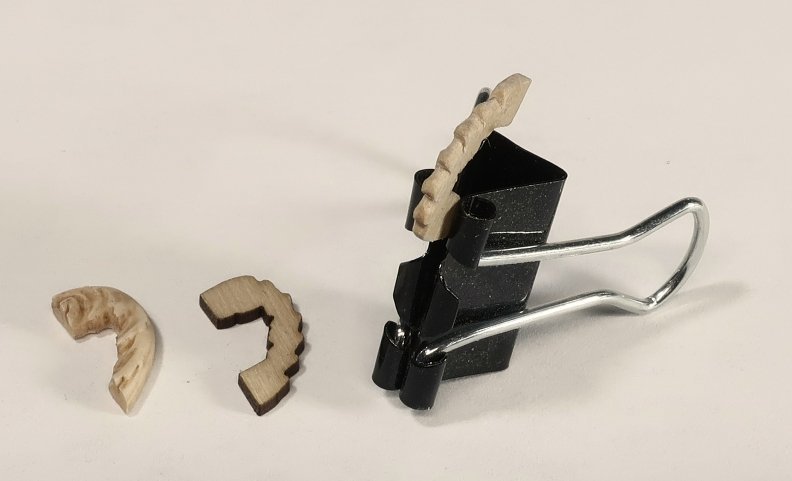
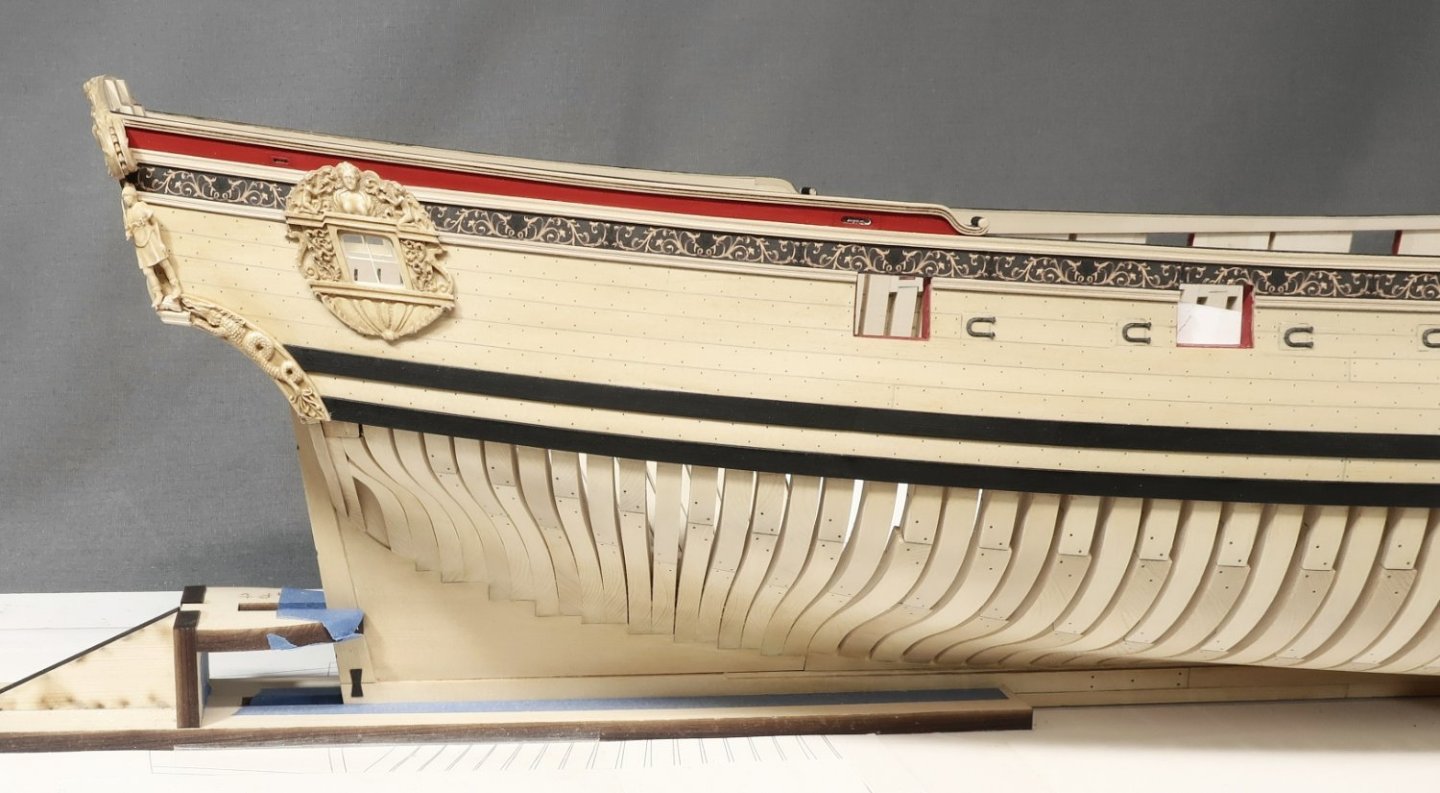
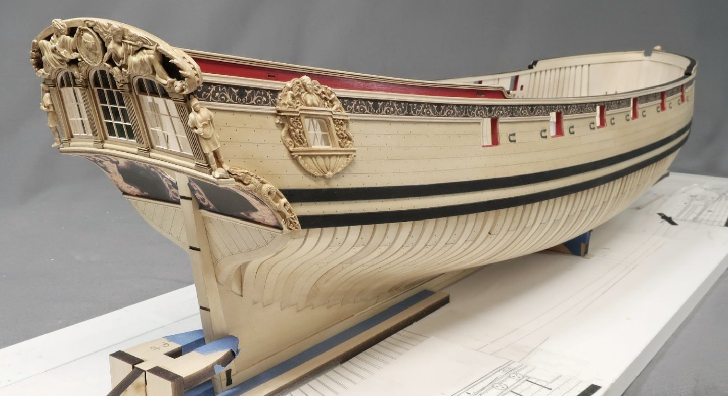
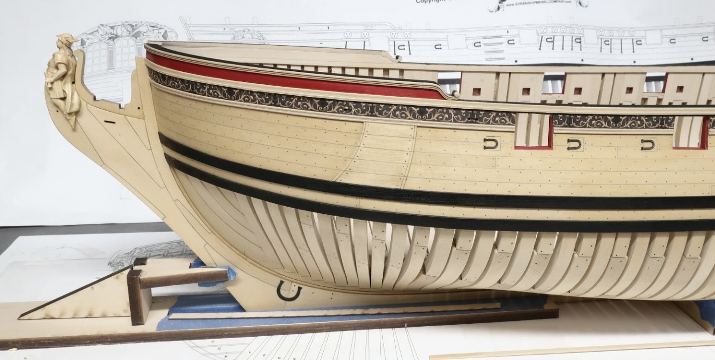
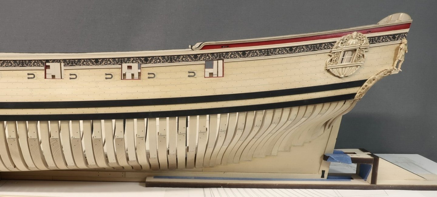
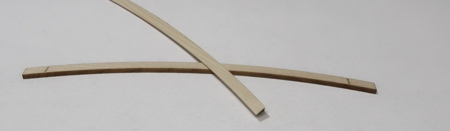
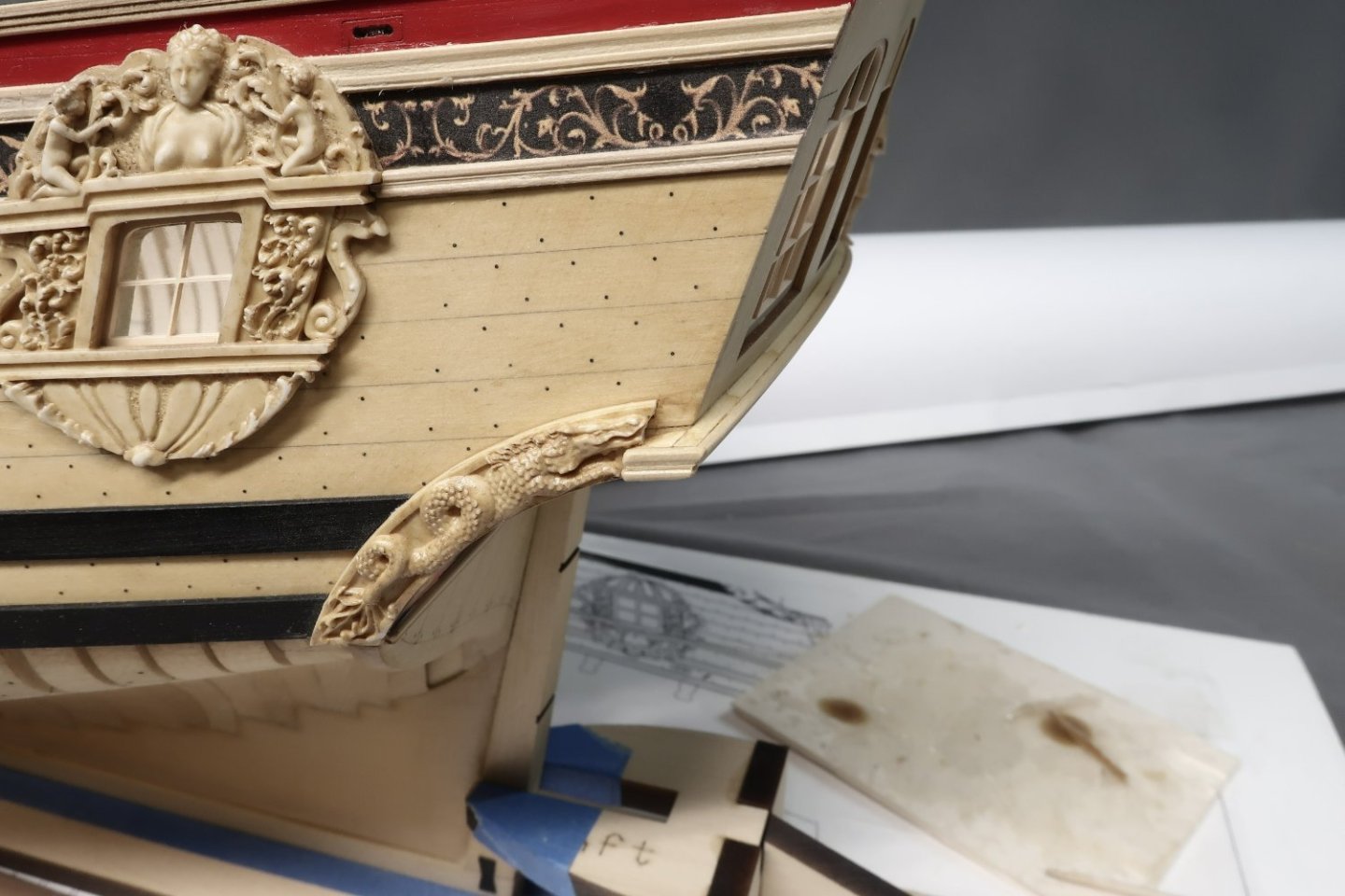
Just a little bit of work today to start chapter 4. I actually did forget to add something for chapter 3 so I just made it the first thing in this new chapter. That was the anchor lining. Its pretty straight forward. Each strake of the anchor lining is laser cut although it may not line up perfectly with everyone's planking on individual models. You guys may make some planks narrower or taper them less up there. But its better to have them I suppose and if folks have to they can easily make them from scratch. Then starts the stern details... First up was to scratch some molding for the lowest one just above the square tuck. You guys have done this before. 1/8" x 1/32" strip of boxwood scraped. Then the frieze was cut out and glued on. The darker one of course to match the friezes on the side of the hull. Then the upper molding above the frieze was added. It was done in two layer. The first is laser cut for you on a curve to match the curve of the transom. There are registration marks to help center it etched onto the FORWARD side of the molding. This is the side that gets glued to the transom. The AFT side of this strip need to be sanded with an angle along its entire length. This helps establish the correct angles of the second layer which we will add later. The laser cut piece on the bottom is a non sanded example just to show the laser etched lines that help you center it. The ends will hang over on both sides of the hull quite a bit. That is by design. But you can see the other example on top which has been sanded along its entire length on an angle, basically making it triangular in profile or wedge shaped. This can be glued on the model once completed. Thats when you can scrape another length of 1/8" x 1/16" boxwood strip which can be glued on top of it. Its just a cheat to help establish the correct angles of this complex piece of molding. Then the sides are completed and trimmed which is a boring long process I wont bother posting here...bit in the end you get this below. You can see how it extends beyond the side to create a little platform. This is for the standing figure. Its not time to glue these figures on permanently yet....but I did want to do a test to check its size and fit and placement. I removed them right after. Note how the figures follow the angle of the transom when viewed from the side of the hull. The figure was designed to look like it was stepping forward and leaning. This is important for the look of the model. They face almost outward from the side so the front of the torso almost faces port and starboard. Although there is a slight turn aft as well. One foot also slightly hangs over the molding which is correct but maybe not this much once I actually glue them on permanently. Thats it for now but a little painting is next up so I can continue work on the stern. There are the typical columns and such as well as the carvings above the windows. Chuck

-
Twenty three pages of crap topics whittled down to less than one page. Its back....but please nobody start another junk topic like that. You know who you are. One more meme and its gone for good. Lets see who the first member will be....want to take any bets?
-
No not really…One or two topics like that is fine. But it snowballed into about 300 most created by the same two or three guys and one guy in particular started about 200 of them.
-
Ooofff!!! $1700 for that. I feel so much better now. That is a really peculiar looking model on so many levels. If you are gonna leave that much space between frames they should stick to POB. For that much $$$ and it looks so Kit-like…its doubtful any bashing can fix that. Unless you fully plank it. I hate to say it. Bit then what can possibly be done to fix the rest. Oh the headrails…I cant look it anymore, LoL Good luck to those building it. It will certainly be interesting to watch.
- 56 replies
-
- 11
-
-

-
Nope…those are gone once deleted. Sorry
-
That can be easily rectified. .....in fact its done along with a few other fan favorites. Now in nautical general discussion. As for the remaining....stick a fork in my eye....do I really have to go through this nonsense? I could be model building instead? Literally dozens more posted every few minutes....sometimes I hate my job. 150,000 posts to weed through.

-
Stevinee...yes you are correct. But it got out of hand. We thought it would be used by members to showcase other hobbies....The gardening....maybe astronomy or photography among birthday greetings etc. Maybe a few fun topics. But as with all things a few bad apples even after being warned used the forum for their own personal facebook site. Posting bad jokes and memes and minions....by the thousands. That is never what we ever thought it was going to turn into or become. A distraction. So no harm done. There may be a few members that are so put off by its removal that they leave....but remember they never posting anything else but that stuff. So no great loss. I hope this rebalances the site and maybe in the future we can bring it back. But I fear it would be impossible to police and moderate properly. There will always be somebody that says his love of funny traffic signs is his other hobby and just as important as someone's other hobby of gardening. And thus we will always end up with talking and dancing cats....bad jokes and quirky "doctors office moments" or "your funniest cooking mistake...the list is endless. That is called facebook. Back to model building!!! Chuck
- 22 replies
-
- 10
-
-
-
The non ship model builds are still there. In fact its more prominent. That section has not been removed at all. AND it wont ever be removed. Just the meme forum was temporarily removed!!! Its still a model. I think dancing cats and bad dad jokes are a far cry from other model building content. Not even close or fair to compare the two...where many of the same techniques are used and described which helps folks. You guys would not believe that as much as 45% to 50% of the posts made every day were of dancing cats and funny signs. Somewhere many of you have lost your focus of what this site is all about. Many of you post upwards of a dozen useless jokes and cartoons each day while not posting anything else ship model related. This is NOT that kind of site. Stick to model building stuff!!! Its great to post a few off topic posts...but too many of the usual suspects took the site for granted at everyone else's expense for their own personal gratification. I have been one of the longest members here being member number tTWO actually. I might have 100 topics that I have posted since then...but we literally had two guys that havent been here half as long as me who have posted HUNDREDS of these meme topics. Hundreds if not thousands of copy/pasted photos of nonsense. AND zero.....I repeat...zero stand alone topics that have anything to do with model building. Funny thing...I spent a half hour pruning about 30 photos that literally had copyright watermarks on them. When I returned to the shore leave forum after that, I discovered that the same freaking guy had posted about 40 more new ones. How is that even possible? I could just give that guy the boot and maybe a half dozen others as they were warned many times. But it always ...always goes back to the way it was. This unfortunately snowballed and encouraged many of our members who do actually post model stuff to also pile on and post a several nonsense topics. The sheer number of these topics/photos and distractions are NOT good for advancing ship modeling as a whole. And its not fun for our moderators and admin. not fair to compare to this.....I have 150,000 of these useless posts and topics to wade through...Thanks guys.

- 22 replies
-
- 14
-
-
Lots of cat memes and funny sign photos to prune for copyright infringements and yada yada... Over 150,000 posts of "what folks had for dinner" and "Old guy parking quirks" This may take a while. In the meanwhile....direct your attention to the other forum areas dedicated to the wonderful world of ship modeling!!! AND please.....do not post one Minion meme in any of the other areas.....wink wink....you know who you are...resist the urge. And yes we still do have a Nautical General discussion forum that should fit your needs for most other stuff other than topics about "those old jokes" and the likes.
-
Beautiful progress…and its good to see you back at it. if the museum would be up to it…ask them if you could post progress on the restoration. Sounds like an interesting project.
-
Lovely design...I am eagerly awaiting your progress. Chuck
-
Unfortunately when you are using the woods we use it becomes impossible to outsource. That creates another huge problem. Getting enough wood milled in Boxwood or Yellow Cedar is tough enough. Having it shipped to supply another laser cutter is impossible. The costs would increase by another 30 to 35%. I Have gotten quotes for laser cutting and its ridiculous. In fact I do outsource some laser cutting where I use plywood, the Winnie bulkheads for example. But the limited woods they carry are problematic unless I start using Basswood like every other manufacturer. I may laser cut one Speedwell in Basswood just to see how it looks. But I have to find someone willing to build it. If it works I could have a dozen ready to go in no time at all!!! But if someone is spending this money they dont want to use basswood. If I were to use Basswood or any other wood not suitable for better ship models it would be an easy solution. I would be cutting more Speedwell parts right now if I had the milled wood on the shelf. Logistics are awful. But like I said…I wont limit the number of Speedwell kits but they will be slow in the making. Getting regular shipments of 100's of milled yellow cedar sheets or Boxwood sheets is not an easy task. And its super expensive. I will always keep one or two of each chapter on the shelf. Remember at the same time I am still laser cutting Winnie parts and Cheerful parts and a whole host of others. Laser time is the easy part...getting material is another.
-
HM Cutter Cheerful 1806 by Erik W - 1:48 scale
Chuck replied to Erik W's topic in - Build logs for subjects built 1801 - 1850
Beautifully done...