


Erik W
-
Posts
427 -
Joined
-
Last visited
Reputation Activity
-

 Erik W got a reaction from scrubbyj427 in HM Cutter Cheerful 1806 by Erik W - 1:48 scale
Thanks for the kind words and likes folks! This week's progress was getting the fancy molding on the edge of the cap rail. I used the same method as I did creating the other fancy molding, but once the profile was scraped in I sanded the back side down to reduce the 1/32" thickness so it wouldn't add too much to the overall cap rail width.
My next task was making the stern gun port lids. Back when I completed the planking on the stern, the gun port interior framing did not line up correctly with the stern planking. A bit of an irritant, but I knew with the port lids modeled closed, it wouldn't be noticeable when all was said and done. The top photo below show the misaligned interior port and planking. The port lids pictured below are the 5th and 6th ones I made. I wanted to get the exterior planking lined up correctly as well as the lid interior level and lined up correctly also since you can see the individual boards under the slightly opaque covering of red paint (hard to see in these photos). The port lids are a bit Frankenstein-like, but look correct from both the interior and exterior.
The port lid hinges were ordered from Chuck 7 or so years ago (it looks like he has updated those hinge kits since back then). To simulate the actual hinge I used .030" styrene rod painted black along with the hinge straps. The rings at the bottoms are made from the .016" wire that came with the port hinges secured with a small loop of .010" brass wire.
Erik
-
 Erik W got a reaction from GuntherMT in HM Cutter Cheerful 1806 by Erik W - 1:48 scale
Thanks for the kind words and likes folks! This week's progress was getting the fancy molding on the edge of the cap rail. I used the same method as I did creating the other fancy molding, but once the profile was scraped in I sanded the back side down to reduce the 1/32" thickness so it wouldn't add too much to the overall cap rail width.
My next task was making the stern gun port lids. Back when I completed the planking on the stern, the gun port interior framing did not line up correctly with the stern planking. A bit of an irritant, but I knew with the port lids modeled closed, it wouldn't be noticeable when all was said and done. The top photo below show the misaligned interior port and planking. The port lids pictured below are the 5th and 6th ones I made. I wanted to get the exterior planking lined up correctly as well as the lid interior level and lined up correctly also since you can see the individual boards under the slightly opaque covering of red paint (hard to see in these photos). The port lids are a bit Frankenstein-like, but look correct from both the interior and exterior.
The port lid hinges were ordered from Chuck 7 or so years ago (it looks like he has updated those hinge kits since back then). To simulate the actual hinge I used .030" styrene rod painted black along with the hinge straps. The rings at the bottoms are made from the .016" wire that came with the port hinges secured with a small loop of .010" brass wire.
Erik
-
 Erik W got a reaction from MikeB4 in HM Cutter Cheerful 1806 by Erik W - 1:48 scale
Thanks for the kind words and likes folks! This week's progress was getting the fancy molding on the edge of the cap rail. I used the same method as I did creating the other fancy molding, but once the profile was scraped in I sanded the back side down to reduce the 1/32" thickness so it wouldn't add too much to the overall cap rail width.
My next task was making the stern gun port lids. Back when I completed the planking on the stern, the gun port interior framing did not line up correctly with the stern planking. A bit of an irritant, but I knew with the port lids modeled closed, it wouldn't be noticeable when all was said and done. The top photo below show the misaligned interior port and planking. The port lids pictured below are the 5th and 6th ones I made. I wanted to get the exterior planking lined up correctly as well as the lid interior level and lined up correctly also since you can see the individual boards under the slightly opaque covering of red paint (hard to see in these photos). The port lids are a bit Frankenstein-like, but look correct from both the interior and exterior.
The port lid hinges were ordered from Chuck 7 or so years ago (it looks like he has updated those hinge kits since back then). To simulate the actual hinge I used .030" styrene rod painted black along with the hinge straps. The rings at the bottoms are made from the .016" wire that came with the port hinges secured with a small loop of .010" brass wire.
Erik
-
 Erik W got a reaction from JesseLee in HM Cutter Cheerful 1806 by Erik W - 1:48 scale
Thanks for the kind words and likes folks! This week's progress was getting the fancy molding on the edge of the cap rail. I used the same method as I did creating the other fancy molding, but once the profile was scraped in I sanded the back side down to reduce the 1/32" thickness so it wouldn't add too much to the overall cap rail width.
My next task was making the stern gun port lids. Back when I completed the planking on the stern, the gun port interior framing did not line up correctly with the stern planking. A bit of an irritant, but I knew with the port lids modeled closed, it wouldn't be noticeable when all was said and done. The top photo below show the misaligned interior port and planking. The port lids pictured below are the 5th and 6th ones I made. I wanted to get the exterior planking lined up correctly as well as the lid interior level and lined up correctly also since you can see the individual boards under the slightly opaque covering of red paint (hard to see in these photos). The port lids are a bit Frankenstein-like, but look correct from both the interior and exterior.
The port lid hinges were ordered from Chuck 7 or so years ago (it looks like he has updated those hinge kits since back then). To simulate the actual hinge I used .030" styrene rod painted black along with the hinge straps. The rings at the bottoms are made from the .016" wire that came with the port hinges secured with a small loop of .010" brass wire.
Erik
-
 Erik W got a reaction from archjofo in HM Cutter Cheerful 1806 by Erik W - 1:48 scale
Thanks for the kind words and likes folks! This week's progress was getting the fancy molding on the edge of the cap rail. I used the same method as I did creating the other fancy molding, but once the profile was scraped in I sanded the back side down to reduce the 1/32" thickness so it wouldn't add too much to the overall cap rail width.
My next task was making the stern gun port lids. Back when I completed the planking on the stern, the gun port interior framing did not line up correctly with the stern planking. A bit of an irritant, but I knew with the port lids modeled closed, it wouldn't be noticeable when all was said and done. The top photo below show the misaligned interior port and planking. The port lids pictured below are the 5th and 6th ones I made. I wanted to get the exterior planking lined up correctly as well as the lid interior level and lined up correctly also since you can see the individual boards under the slightly opaque covering of red paint (hard to see in these photos). The port lids are a bit Frankenstein-like, but look correct from both the interior and exterior.
The port lid hinges were ordered from Chuck 7 or so years ago (it looks like he has updated those hinge kits since back then). To simulate the actual hinge I used .030" styrene rod painted black along with the hinge straps. The rings at the bottoms are made from the .016" wire that came with the port hinges secured with a small loop of .010" brass wire.
Erik
-
 Erik W got a reaction from Ryland Craze in 18th Century Longboat by Erik W - FINISHED - Model Shipways - Scale 1:48 - First wooden ship build
The mast is complete. I haven't permanently attached it to the boat yet. I'll do that after I get the bowsprit completed and attached.
Erik
-
 Erik W got a reaction from bruce d in HM Cutter Cheerful 1806 by Erik W - 1:48 scale
Thanks for the kind words and likes folks! This week's progress was getting the fancy molding on the edge of the cap rail. I used the same method as I did creating the other fancy molding, but once the profile was scraped in I sanded the back side down to reduce the 1/32" thickness so it wouldn't add too much to the overall cap rail width.
My next task was making the stern gun port lids. Back when I completed the planking on the stern, the gun port interior framing did not line up correctly with the stern planking. A bit of an irritant, but I knew with the port lids modeled closed, it wouldn't be noticeable when all was said and done. The top photo below show the misaligned interior port and planking. The port lids pictured below are the 5th and 6th ones I made. I wanted to get the exterior planking lined up correctly as well as the lid interior level and lined up correctly also since you can see the individual boards under the slightly opaque covering of red paint (hard to see in these photos). The port lids are a bit Frankenstein-like, but look correct from both the interior and exterior.
The port lid hinges were ordered from Chuck 7 or so years ago (it looks like he has updated those hinge kits since back then). To simulate the actual hinge I used .030" styrene rod painted black along with the hinge straps. The rings at the bottoms are made from the .016" wire that came with the port hinges secured with a small loop of .010" brass wire.
Erik
-
 Erik W got a reaction from CiscoH in HM Cutter Cheerful 1806 by Erik W - 1:48 scale
Thanks for the kind words and likes folks! This week's progress was getting the fancy molding on the edge of the cap rail. I used the same method as I did creating the other fancy molding, but once the profile was scraped in I sanded the back side down to reduce the 1/32" thickness so it wouldn't add too much to the overall cap rail width.
My next task was making the stern gun port lids. Back when I completed the planking on the stern, the gun port interior framing did not line up correctly with the stern planking. A bit of an irritant, but I knew with the port lids modeled closed, it wouldn't be noticeable when all was said and done. The top photo below show the misaligned interior port and planking. The port lids pictured below are the 5th and 6th ones I made. I wanted to get the exterior planking lined up correctly as well as the lid interior level and lined up correctly also since you can see the individual boards under the slightly opaque covering of red paint (hard to see in these photos). The port lids are a bit Frankenstein-like, but look correct from both the interior and exterior.
The port lid hinges were ordered from Chuck 7 or so years ago (it looks like he has updated those hinge kits since back then). To simulate the actual hinge I used .030" styrene rod painted black along with the hinge straps. The rings at the bottoms are made from the .016" wire that came with the port hinges secured with a small loop of .010" brass wire.
Erik
-
 Erik W got a reaction from Ainars in HM Cutter Cheerful 1806 by Erik W - 1:48 scale
Thanks for the kind words and likes folks! This week's progress was getting the fancy molding on the edge of the cap rail. I used the same method as I did creating the other fancy molding, but once the profile was scraped in I sanded the back side down to reduce the 1/32" thickness so it wouldn't add too much to the overall cap rail width.
My next task was making the stern gun port lids. Back when I completed the planking on the stern, the gun port interior framing did not line up correctly with the stern planking. A bit of an irritant, but I knew with the port lids modeled closed, it wouldn't be noticeable when all was said and done. The top photo below show the misaligned interior port and planking. The port lids pictured below are the 5th and 6th ones I made. I wanted to get the exterior planking lined up correctly as well as the lid interior level and lined up correctly also since you can see the individual boards under the slightly opaque covering of red paint (hard to see in these photos). The port lids are a bit Frankenstein-like, but look correct from both the interior and exterior.
The port lid hinges were ordered from Chuck 7 or so years ago (it looks like he has updated those hinge kits since back then). To simulate the actual hinge I used .030" styrene rod painted black along with the hinge straps. The rings at the bottoms are made from the .016" wire that came with the port hinges secured with a small loop of .010" brass wire.
Erik
-

 Erik W got a reaction from egkb in HM Cutter Cheerful 1806 by Erik W - 1:48 scale
Thanks for the kind words and likes folks! This week's progress was getting the fancy molding on the edge of the cap rail. I used the same method as I did creating the other fancy molding, but once the profile was scraped in I sanded the back side down to reduce the 1/32" thickness so it wouldn't add too much to the overall cap rail width.
My next task was making the stern gun port lids. Back when I completed the planking on the stern, the gun port interior framing did not line up correctly with the stern planking. A bit of an irritant, but I knew with the port lids modeled closed, it wouldn't be noticeable when all was said and done. The top photo below show the misaligned interior port and planking. The port lids pictured below are the 5th and 6th ones I made. I wanted to get the exterior planking lined up correctly as well as the lid interior level and lined up correctly also since you can see the individual boards under the slightly opaque covering of red paint (hard to see in these photos). The port lids are a bit Frankenstein-like, but look correct from both the interior and exterior.
The port lid hinges were ordered from Chuck 7 or so years ago (it looks like he has updated those hinge kits since back then). To simulate the actual hinge I used .030" styrene rod painted black along with the hinge straps. The rings at the bottoms are made from the .016" wire that came with the port hinges secured with a small loop of .010" brass wire.
Erik
-
 Erik W got a reaction from Tigersteve in HM Cutter Cheerful 1806 by Erik W - 1:48 scale
Thanks for the kind words and likes folks! This week's progress was getting the fancy molding on the edge of the cap rail. I used the same method as I did creating the other fancy molding, but once the profile was scraped in I sanded the back side down to reduce the 1/32" thickness so it wouldn't add too much to the overall cap rail width.
My next task was making the stern gun port lids. Back when I completed the planking on the stern, the gun port interior framing did not line up correctly with the stern planking. A bit of an irritant, but I knew with the port lids modeled closed, it wouldn't be noticeable when all was said and done. The top photo below show the misaligned interior port and planking. The port lids pictured below are the 5th and 6th ones I made. I wanted to get the exterior planking lined up correctly as well as the lid interior level and lined up correctly also since you can see the individual boards under the slightly opaque covering of red paint (hard to see in these photos). The port lids are a bit Frankenstein-like, but look correct from both the interior and exterior.
The port lid hinges were ordered from Chuck 7 or so years ago (it looks like he has updated those hinge kits since back then). To simulate the actual hinge I used .030" styrene rod painted black along with the hinge straps. The rings at the bottoms are made from the .016" wire that came with the port hinges secured with a small loop of .010" brass wire.
Erik
-
 Erik W got a reaction from tlevine in HM Cutter Cheerful 1806 by Erik W - 1:48 scale
Thanks for the kind words and likes folks! This week's progress was getting the fancy molding on the edge of the cap rail. I used the same method as I did creating the other fancy molding, but once the profile was scraped in I sanded the back side down to reduce the 1/32" thickness so it wouldn't add too much to the overall cap rail width.
My next task was making the stern gun port lids. Back when I completed the planking on the stern, the gun port interior framing did not line up correctly with the stern planking. A bit of an irritant, but I knew with the port lids modeled closed, it wouldn't be noticeable when all was said and done. The top photo below show the misaligned interior port and planking. The port lids pictured below are the 5th and 6th ones I made. I wanted to get the exterior planking lined up correctly as well as the lid interior level and lined up correctly also since you can see the individual boards under the slightly opaque covering of red paint (hard to see in these photos). The port lids are a bit Frankenstein-like, but look correct from both the interior and exterior.
The port lid hinges were ordered from Chuck 7 or so years ago (it looks like he has updated those hinge kits since back then). To simulate the actual hinge I used .030" styrene rod painted black along with the hinge straps. The rings at the bottoms are made from the .016" wire that came with the port hinges secured with a small loop of .010" brass wire.
Erik
-
 Erik W reacted to Chuck in Sloop Speedwell 1752 by Chuck - Ketch Rigged Sloop - POF - prototype build
Just a little bit of work today to start chapter 4.
I actually did forget to add something for chapter 3 so I just made it the first thing in this new chapter. That was the anchor lining. Its pretty straight forward. Each strake of the anchor lining is laser cut although it may not line up perfectly with everyone's planking on individual models. You guys may make some planks narrower or taper them less up there. But its better to have them I suppose and if folks have to they can easily make them from scratch.
Then starts the stern details...
First up was to scratch some molding for the lowest one just above the square tuck. You guys have done this before. 1/8" x 1/32" strip of boxwood scraped.
Then the frieze was cut out and glued on. The darker one of course to match the friezes on the side of the hull.
Then the upper molding above the frieze was added. It was done in two layer. The first is laser cut for you on a curve to match the curve of the transom. There are registration marks to help center it etched onto the FORWARD side of the molding. This is the side that gets glued to the transom. The AFT side of this strip need to be sanded with an angle along its entire length. This helps establish the correct angles of the second layer which we will add later. The laser cut piece on the bottom is a non sanded example just to show the laser etched lines that help you center it. The ends will hang over on both sides of the hull quite a bit. That is by design. But you can see the other example on top which has been sanded along its entire length on an angle, basically making it triangular in profile or wedge shaped. This can be glued on the model once completed.
Thats when you can scrape another length of 1/8" x 1/16" boxwood strip which can be glued on top of it. Its just a cheat to help establish the correct angles of this complex piece of molding.
Then the sides are completed and trimmed which is a boring long process I wont bother posting here...bit in the end you get this below. You can see how it extends beyond the side to create a little platform. This is for the standing figure.
Its not time to glue these figures on permanently yet....but I did want to do a test to check its size and fit and placement. I removed them right after. Note how the figures follow the angle of the transom when viewed from the side of the hull. The figure was designed to look like it was stepping forward and leaning. This is important for the look of the model. They face almost outward from the side so the front of the torso almost faces port and starboard. Although there is a slight turn aft as well. One foot also slightly hangs over the molding which is correct but maybe not this much once I actually glue them on permanently.
Thats it for now but a little painting is next up so I can continue work on the stern. There are the typical columns and such as well as the carvings above the windows.
Chuck
-
Erik W got a reaction from GuntherMT in HM Cutter Cheerful 1806 by Erik W - 1:48 scale
I was out of town visiting family in Annapolis, Maryland, for a few days this week. While there, I went to the US Naval Academy Museum. Not my first visit there, but always a fun outing. And grabbing lunch downtown afterwards is a must as well. On the 2nd floor, the museum houses the Rogers Collection of wooden ship dockyard models, as well as newer built models from all eras of naval history on the 1st floor. If you haven't been to this museum, I highly recommend it.
I did manage to make some progress on my Cheerful. I added the cap rail. The cap rail is 7 pieces cut out of 1/16" sheet. One piece for the stern, and 3 for each side. I have quality digital calipers accurate to .0001" to measure with, so getting the rail to a uniform width was easy enough, it just took some time to sand down. The cap rail measures in at a bit under 5/32" wide. I also fashioned the hawse plates out of 1/32" thick sheet. This was pretty straight forward with first cutting the plan out and then transferring the lines to the wood sheet. Drilling the hawse holes in the hawse plates and bulwarks was pretty easy as well. I had an issue with drilling and filing the bowsprit hole though. While the hole was aligned properly, parallel to the keel and level with the keel, I got a bit carried away with enlarging the diameter up to the final bowsprit diameter. When I inserted the a 5/16" drill bit shaft to double check the diameter, there was a little slop as it passed through the hawse plate. I did that thing where I tried to convince myself I could live with it. I couldn't. So, I pried it off and fabricated a new one. This time though I deliberately left the bowsprit hole a smaller diameter than what the bowsprit will be. I figure it makes the most sense to tweak the hole diameter when I have the bowsprit made, so I can adjust it to the actual diameter. Live and learn.
Erik
-
 Erik W got a reaction from Javelin in HM Cutter Cheerful 1806 by Erik W - 1:48 scale
I was out of town visiting family in Annapolis, Maryland, for a few days this week. While there, I went to the US Naval Academy Museum. Not my first visit there, but always a fun outing. And grabbing lunch downtown afterwards is a must as well. On the 2nd floor, the museum houses the Rogers Collection of wooden ship dockyard models, as well as newer built models from all eras of naval history on the 1st floor. If you haven't been to this museum, I highly recommend it.
I did manage to make some progress on my Cheerful. I added the cap rail. The cap rail is 7 pieces cut out of 1/16" sheet. One piece for the stern, and 3 for each side. I have quality digital calipers accurate to .0001" to measure with, so getting the rail to a uniform width was easy enough, it just took some time to sand down. The cap rail measures in at a bit under 5/32" wide. I also fashioned the hawse plates out of 1/32" thick sheet. This was pretty straight forward with first cutting the plan out and then transferring the lines to the wood sheet. Drilling the hawse holes in the hawse plates and bulwarks was pretty easy as well. I had an issue with drilling and filing the bowsprit hole though. While the hole was aligned properly, parallel to the keel and level with the keel, I got a bit carried away with enlarging the diameter up to the final bowsprit diameter. When I inserted the a 5/16" drill bit shaft to double check the diameter, there was a little slop as it passed through the hawse plate. I did that thing where I tried to convince myself I could live with it. I couldn't. So, I pried it off and fabricated a new one. This time though I deliberately left the bowsprit hole a smaller diameter than what the bowsprit will be. I figure it makes the most sense to tweak the hole diameter when I have the bowsprit made, so I can adjust it to the actual diameter. Live and learn.
Erik
-
Erik W got a reaction from GuntherMT in HM Cutter Cheerful 1806 by Erik W - 1:48 scale
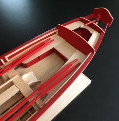
Over the last week I planked the port side bulwarks. I spent a few hours today doing the final sanding of both sides of the bulwarks which included thinning the areas of the bulwarks tops that were thicker than the others in preparation for adding the cap rail. I carefully thinned the 1/32" thick spirketing to a thickness somewhere between 1/32" and 1/64". I then rounded the edge of the top spirketing plank a bit. Lastly I softened the edges on the stern frames to reflect the look of Chuck's visible stern frames on his Cheerful build.
Erik
-
Erik W got a reaction from GuntherMT in HM Cutter Cheerful 1806 by Erik W - 1:48 scale
Ian, Thanks for the kind words! I have had your Cheerful build bookmarked. I like the way your Cheerful has more bare wood showing than most. It looks great! And thanks for noticing my efforts at getting good photos. It actually takes some time to set everything up. Since I photograph on my work surface, I have to move everything out of the way. And I can only really photograph on the weekends when I have time during the day while the sun is shining, as a good portion of the overall lighting is from a window.
I added the 1/32" thick planks below the gun ports. I did these as hull length single planks to keep the plank run looking smooth. I also wound up adding a 1/32" x 1/32" strip along the bow area between the 1st and 2nd gun ports beneath the two main planks. This was probably unnecessary, but when I measured the gap it came out to be pretty close in height to what will be the 3/64" thick deck plank plus the 1/32" thick waterway. So, better safe than sorry. I then did a bit of sanding to thin the 1/32" planking as Chuck suggests in his monograph. Once I have the port side planking to the same point, I'll further thin both sides slightly, and round the hard edge a little. I've always found when modeling 2 sides that are supposed to be symmetrical, completing them to 90% or so, while working on first one side and then the other, and then finishing both sides at the same times helps make it easier to get them where they look identical.
Erik
-
 Erik W got a reaction from Canute in HM Cutter Cheerful 1806 by Erik W - 1:48 scale
Thanks for the likes and nice words guys. And it's always nice to get an 'Outstanding' from Chuck! I installed the false deck this weekend. I used a piece of 24" x 8" x 1/16" basswood. I cut it in half lengthwise and taped the two halves together. I cut the false deck template out of the plans. I then cut all the square deck furniture locators out of the paper plan. I used clear tape to tape this onto the Cheerful (The plan is wavy in my two photos below. It was reattached after the fact for these photos). The clear tape made it easy to locate the center line running through the cutouts. I then followed Chuck's instructions in the Monograph and used masking tape around the edges to get the actual size of the false deck. I removed this carefully and taped the false deck plan to the two basswood sheet halves, again using the clear taped sections of the deck furniture cut outs to locate the center line. Once that was done, I carefully removed the clear tape one section at a time and used the cutout borders to draw their locations on the wood false deck. Reapplying the tape to that square when finished and moving on to the next opening. Once the false deck was cut out of the basswood sheets, I faired the edges to get a good fit. I also wound up adding a thin basswood strip to the stern section of the deck. There had been a bigger gap than I wanted there. I installed each half of the false deck using the visible center of the middle of the five plies of the piece of plywood running lengthwise on the center line as the true center line. Lastly I enlarged the hole in the deck for the mast to it's actual size. I had left it slightly under size when attaching the decks halves, and trued it up afterwords to make sure it was precisely placed where it should be.
Erik
-
Erik W got a reaction from Canute in HM Cutter Cheerful 1806 by Erik W - 1:48 scale
I finished adding the fancy molding to my Cheerful. I planned ahead with the lower molding and didn't glue the portion that will be removed for the addition of the top boarding ladder step. I spent a few evenings thinning and fairing the inboard bulwarks. Yes, this was a messy pain in the butt. There was a bit of a learning curve to sand/fair the inside of a curve vs. fairing the hull planking. The bulwarks framing/gun ports measure in at a hair under 1/16" of an inch thick, which is what Chuck recommended in his monograph. I also faired the bulkhead tops so the false deck will sit flat on them. Lastly, I added the keel plates. I still haven't touched up the paint on the hull exterior, so the build still looks a bit rough at this point. I've decided I'll do that after the deck planking is finished.
Erik
-
Erik W got a reaction from MikeB4 in HM Cutter Cheerful 1806 by Erik W - 1:48 scale
I was out of town visiting family in Annapolis, Maryland, for a few days this week. While there, I went to the US Naval Academy Museum. Not my first visit there, but always a fun outing. And grabbing lunch downtown afterwards is a must as well. On the 2nd floor, the museum houses the Rogers Collection of wooden ship dockyard models, as well as newer built models from all eras of naval history on the 1st floor. If you haven't been to this museum, I highly recommend it.
I did manage to make some progress on my Cheerful. I added the cap rail. The cap rail is 7 pieces cut out of 1/16" sheet. One piece for the stern, and 3 for each side. I have quality digital calipers accurate to .0001" to measure with, so getting the rail to a uniform width was easy enough, it just took some time to sand down. The cap rail measures in at a bit under 5/32" wide. I also fashioned the hawse plates out of 1/32" thick sheet. This was pretty straight forward with first cutting the plan out and then transferring the lines to the wood sheet. Drilling the hawse holes in the hawse plates and bulwarks was pretty easy as well. I had an issue with drilling and filing the bowsprit hole though. While the hole was aligned properly, parallel to the keel and level with the keel, I got a bit carried away with enlarging the diameter up to the final bowsprit diameter. When I inserted the a 5/16" drill bit shaft to double check the diameter, there was a little slop as it passed through the hawse plate. I did that thing where I tried to convince myself I could live with it. I couldn't. So, I pried it off and fabricated a new one. This time though I deliberately left the bowsprit hole a smaller diameter than what the bowsprit will be. I figure it makes the most sense to tweak the hole diameter when I have the bowsprit made, so I can adjust it to the actual diameter. Live and learn.
Erik
-
Erik W got a reaction from GuntherMT in HM Cutter Cheerful 1806 by Erik W - 1:48 scale
Thanks for the likes. My progress this week has been to get the bulwarks painted. I used Vallejo brand Flat Red 70.957. I can't recommend Vallejo paints enough for brush painting. The pigment is extremely fine, and they're easy to apply without any visible brush strokes. I used a new 3/16" wide flat brush to apply 6 thin coats of paint. Every handful of strokes I dipped the brush tip into water to thin the paint, and then applied the paint over several seconds with around half a dozen strokes in a given area. It's important to stop brushing over the area before the paint starts to thicken (thickening causes the brush strokes to be visible). I didn't worry too much about how well each coat covered the surface knowing that I'd continue to apply more coats until I achieved a solid coverage. The important thing with each coat is even coverage with no visible brush strokes.
Erik
-
-
Erik W reacted to Freebird in HM Cutter Cheerful 1806 by Erik W - 1:48 scale
Erik,
Welcome back! Been waiting for you to get back on board as your build is extremely nice. I too have Cheerful on the docks and now that building season is upon us, I’ll be back at it as well. Keep up the great work!
Rick
-
Erik W got a reaction from JesseLee in HM Cutter Cheerful 1806 by Erik W - 1:48 scale
I was out of town visiting family in Annapolis, Maryland, for a few days this week. While there, I went to the US Naval Academy Museum. Not my first visit there, but always a fun outing. And grabbing lunch downtown afterwards is a must as well. On the 2nd floor, the museum houses the Rogers Collection of wooden ship dockyard models, as well as newer built models from all eras of naval history on the 1st floor. If you haven't been to this museum, I highly recommend it.
I did manage to make some progress on my Cheerful. I added the cap rail. The cap rail is 7 pieces cut out of 1/16" sheet. One piece for the stern, and 3 for each side. I have quality digital calipers accurate to .0001" to measure with, so getting the rail to a uniform width was easy enough, it just took some time to sand down. The cap rail measures in at a bit under 5/32" wide. I also fashioned the hawse plates out of 1/32" thick sheet. This was pretty straight forward with first cutting the plan out and then transferring the lines to the wood sheet. Drilling the hawse holes in the hawse plates and bulwarks was pretty easy as well. I had an issue with drilling and filing the bowsprit hole though. While the hole was aligned properly, parallel to the keel and level with the keel, I got a bit carried away with enlarging the diameter up to the final bowsprit diameter. When I inserted the a 5/16" drill bit shaft to double check the diameter, there was a little slop as it passed through the hawse plate. I did that thing where I tried to convince myself I could live with it. I couldn't. So, I pried it off and fabricated a new one. This time though I deliberately left the bowsprit hole a smaller diameter than what the bowsprit will be. I figure it makes the most sense to tweak the hole diameter when I have the bowsprit made, so I can adjust it to the actual diameter. Live and learn.
Erik
-
Erik W got a reaction from archjofo in HM Cutter Cheerful 1806 by Erik W - 1:48 scale
I was out of town visiting family in Annapolis, Maryland, for a few days this week. While there, I went to the US Naval Academy Museum. Not my first visit there, but always a fun outing. And grabbing lunch downtown afterwards is a must as well. On the 2nd floor, the museum houses the Rogers Collection of wooden ship dockyard models, as well as newer built models from all eras of naval history on the 1st floor. If you haven't been to this museum, I highly recommend it.
I did manage to make some progress on my Cheerful. I added the cap rail. The cap rail is 7 pieces cut out of 1/16" sheet. One piece for the stern, and 3 for each side. I have quality digital calipers accurate to .0001" to measure with, so getting the rail to a uniform width was easy enough, it just took some time to sand down. The cap rail measures in at a bit under 5/32" wide. I also fashioned the hawse plates out of 1/32" thick sheet. This was pretty straight forward with first cutting the plan out and then transferring the lines to the wood sheet. Drilling the hawse holes in the hawse plates and bulwarks was pretty easy as well. I had an issue with drilling and filing the bowsprit hole though. While the hole was aligned properly, parallel to the keel and level with the keel, I got a bit carried away with enlarging the diameter up to the final bowsprit diameter. When I inserted the a 5/16" drill bit shaft to double check the diameter, there was a little slop as it passed through the hawse plate. I did that thing where I tried to convince myself I could live with it. I couldn't. So, I pried it off and fabricated a new one. This time though I deliberately left the bowsprit hole a smaller diameter than what the bowsprit will be. I figure it makes the most sense to tweak the hole diameter when I have the bowsprit made, so I can adjust it to the actual diameter. Live and learn.
Erik