gak1965
-
Posts
725 -
Joined
-
Last visited
Content Type
Profiles
Forums
Gallery
Events
Everything posted by gak1965
-
 Thanks Rick! Scroll saw. But I didn't turn the wood, just made a series of cuts in the same direction, starting with the two outer edges. It's only 3/32 inch deep so it's a little easier to stay straight, and I made sure to photograph them from far enough away to hide all of the imperfections 😀 Regards, George
 -
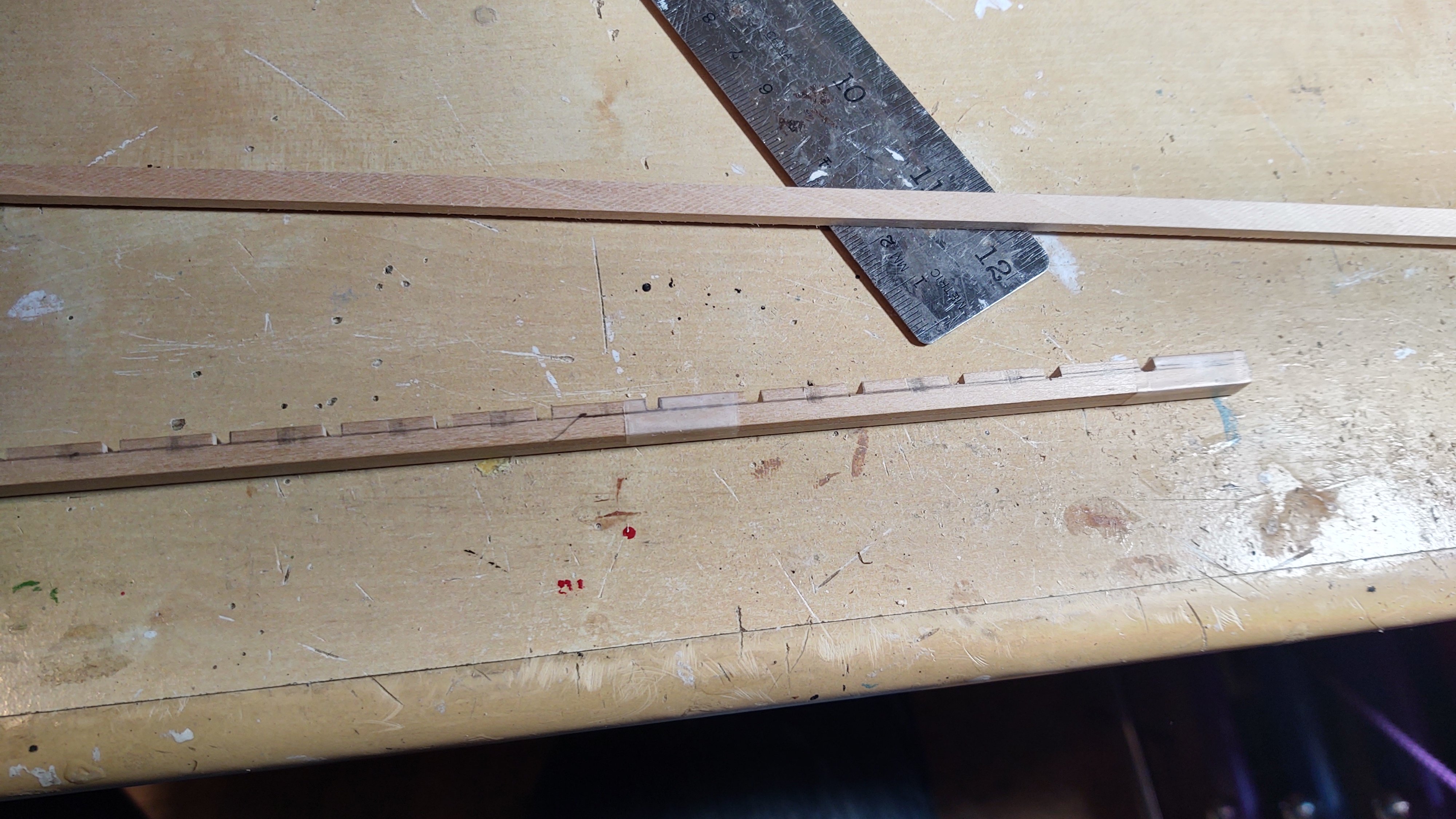
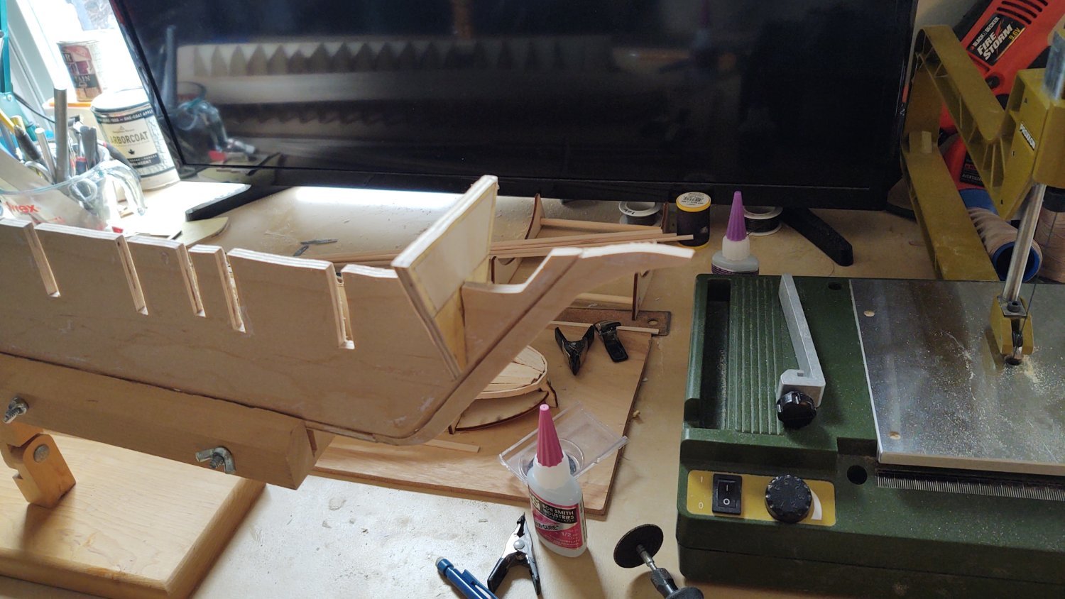
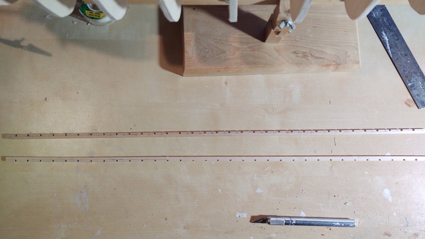
Brief update. Followed the plan described above. I took two pieces of 1/4 by 1/8 bass, taped them together so that the two pieces would be identical, and marked off the 3/32" squares, about 0.7 inches apart, and then started cutting out the 3/32" slots. Here are the two pieces ready to start installing. I soaked them in boiling water to get them to soften for improved bending, and put them on the ship, held in the correct orientation with some clamps and nails to 'prebend' prior to installation. Once dry, they were installed, I glued them into place. Other than some minor smoothing of some of the bulkheads. I can start planking once the lumber arrives. Thanks for looking in! Regards, George


-
You're doing a great job, but yikes, the keel difference and the slots to hold the keel sections together are awful. Maybe worth getting in contact with the Mamoli before you get too much further and see about a replacement? Are you at least confident that your now repaired keel is consistent with the expected size (e.g. they have a plan you can use to validate that it is correct)? I would just hate to find out after you've spent months that there is something else wrong. Regards, George
- 199 replies
-
- 2
-

-
- Flying Cloud
- Mamoli
- (and 1 more)
-
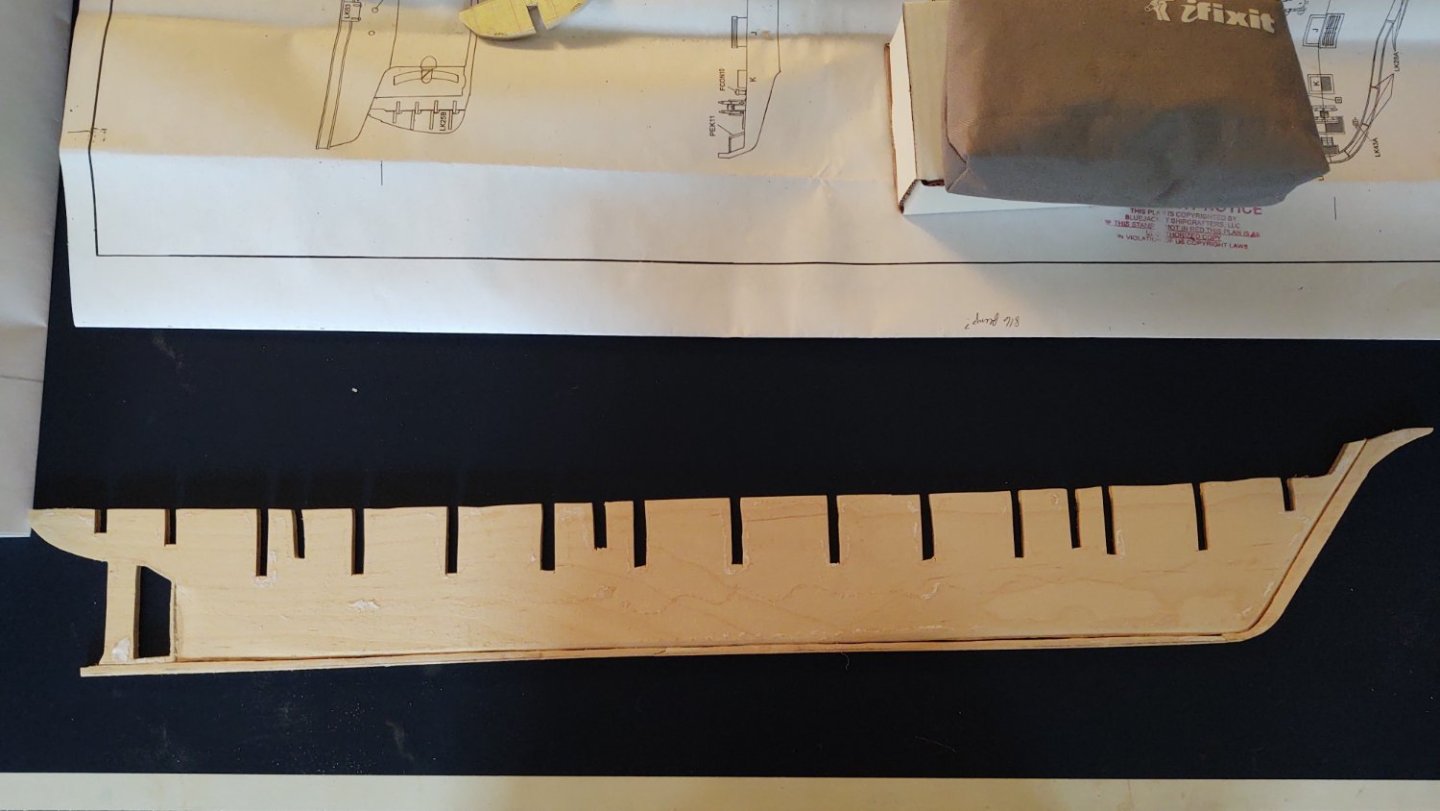
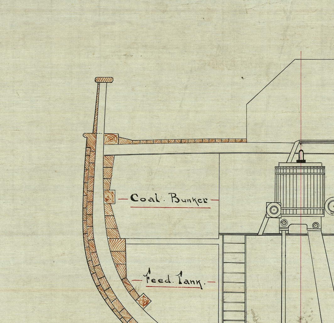
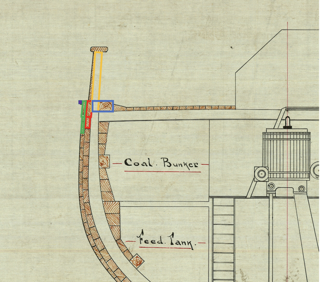
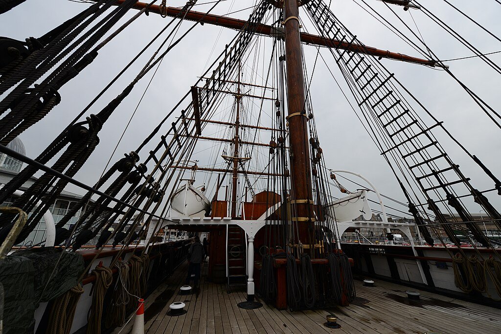
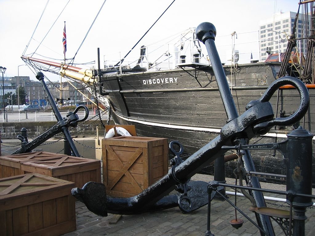
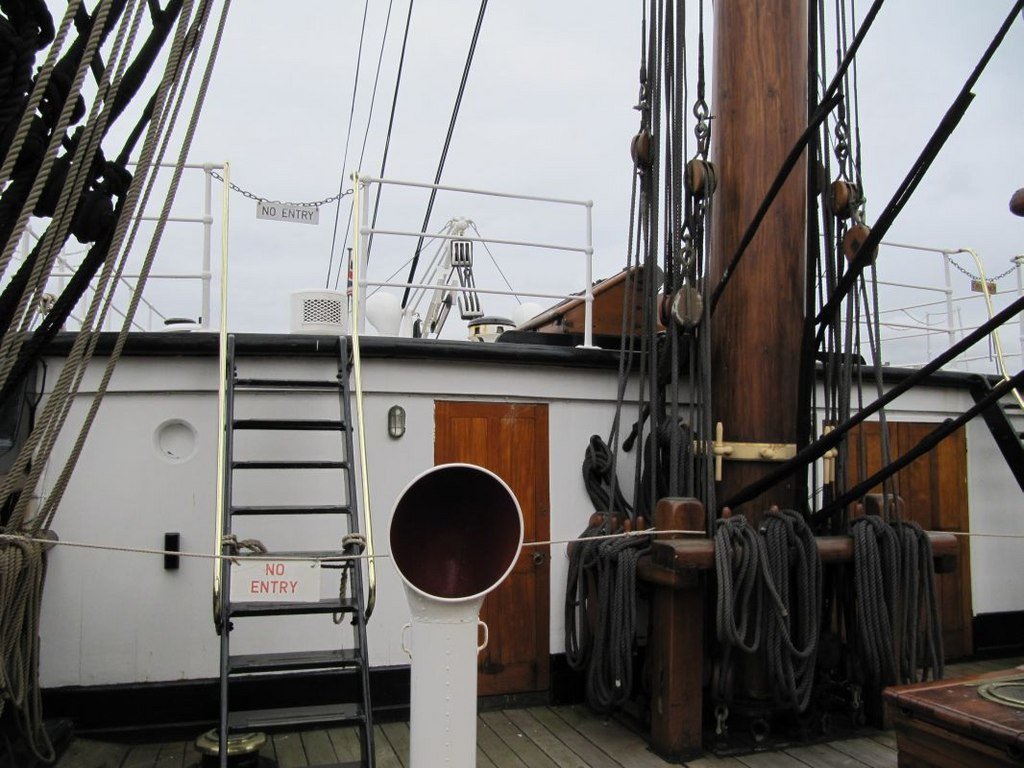
Thanks Peter. It has a long way to go, but there is definitely something fun about designing it yourself. In my case, it probably means I'll do a lot of stupid things, but hey, we learn through our mistakes. Isn't that the truth. The bass knightheads were way softer. The good news is that the stern is going nowhere; it will be a nice solid platform to build on. On the update side, I haven't had a ton of time to work on the ship - there have been some things at work and my wife and I have been doing a major declutter associated with our 15 year anniversary at this home, and based on the fact that I'm pretty confident that we are truly, truly empty nesters (the younger child is going to be leaving her job in Boston to start graduate school in nursing in Philadelphia at the end of the summer, so I am not anticipating her moving back in anytime soon). As part of that, I'm moving my work space into a different location, so we can better use the rec room that I currently work in, etc., etc. However, the move is more or less complete, so back to making sawdust. I did finally finish the filler blocks, so she is ready to start the process that will generate the hull. I've designed her more or less as the Flying Fish kit I built was designed. On the Fish, I laid the waterways on the bulkhead tops flush with the outer edges of the bulkheads, and then the planksheer (cut for the bulwark stanchions) was laid on top of that. The nibbing strake was flush with the waterways and on top of the bulkhead, and the deck laid directly on the bulkheads. This ship is designed slightly different. If you look at the below you will see that the planksheer is kind of integrated into the planking itself, and in addition to the waterway (angled plank), there is a fairly significant timber that is mounted against the frames. As it happens, at 1:72 that timber, plus the extension into the frames works out to 1/4 wide and 1/8 inch tall, a nice, even size that is readily available in bass. So, my plan is as follows: I will build the timber that abuts the waterway and the extensions to the outer edge of the frames from a piece of 1/4 x 1/8 bass, cut to allow a bulwark stanchion to fit (they are spaced about 0.7 inches at scale center to center between the stanchions). This is the blue box on the diagram and it will be aligned with the outside edge of the bulkheads. I will run it for about 22 inches, until the curve becomes too great to efficiently bend, and then will cut out the stern curve with my scroll saw from some 1/8 inch thick basswood. The two layers of planking (red and green) will be added as normal and then a 1/32 inch piece of square bass (purple) will be added on top. Finally I'll make the bulwark stanchions (yellow) out of 3/32 bass and fit them into the slices I cut out of the large 1/8 by 1/4 x 22 piece. One thing that I will need to be careful about is ensuring that the bulwarks have the correct angle, because the ship I think that will work, and produce something that resembles the real thing as below: Photo by Michael Garlick, retrieved from Wikimedia Commons (https://commons.wikimedia.org/wiki/File:RRS_Discovery_Dundee_Main_mast_rigging.JPG) under license CC-BY-SA-4.0) One thing to note is that the Discovery in common with a lot of other ships of that era has "floating" bulwark extensions, that is, they were separate timbers that were not extensions of the frames. Since the bulwarks tended to rot faster, it was simpler to seal and maintain them if all you needed to do was pull a single timber out and not have to mess with the frames. That will not be obvious from the model, but it is the way that the ship was built. Also interestingly, I had assumed that the extension that I am modeling as the 1/32 square plank was where the white stripe was painted, but looking more carefully, the stripe is actually painted just below that plank, and it points to something I need to be careful about - the angle of the bulwarks. If you look at the photo below, you will see that the ship doesn't really have channels where the chain plates are, so making sure I have adequate clearance to drill the holes for the chainplates is going to be important. Photo by Magnus Hagdorn, retrieved from Wikimedia Commons (https://upload.wikimedia.org/wikipedia/commons/thumb/5/55/2007_-_Trip_to_Dundee_(4000147227).jpg/1024px-2007_-_Trip_to_Dundee_(4000147227).jpg) under license CC-BY-SA-2.0 generic) Anyways, as always, thanks for looking in! Please let me know if I have mangled the terminology somewhere. Regards, George
-
Great job! Those gin blocks are a pain in the posterior. Your solution looks fabulous. Regards, George
-
Thanks Rick. Looking forward to the next update on your Flying Fish. It's going to be the best of the bunch that are on MSW. Regards, George
-
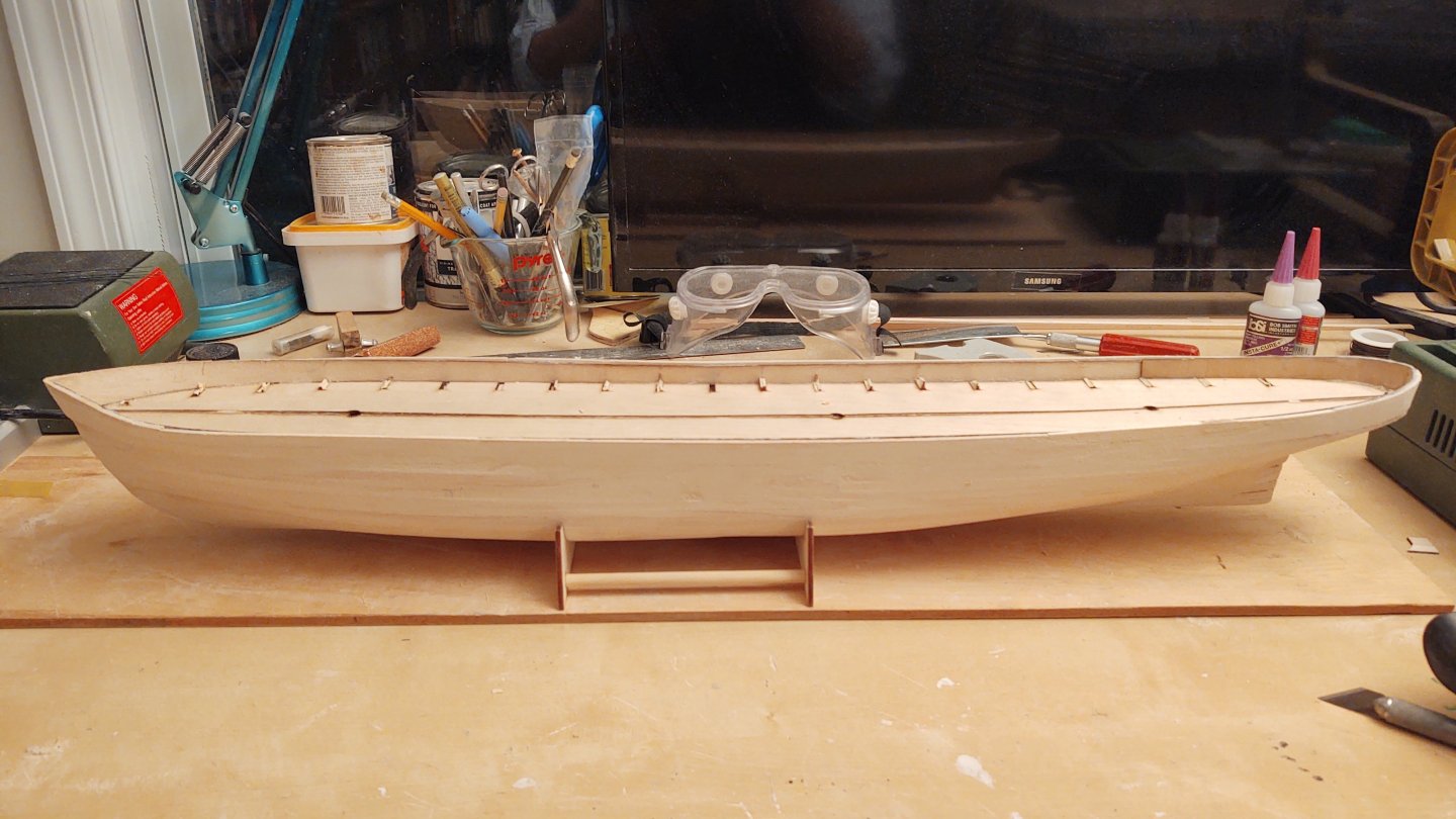
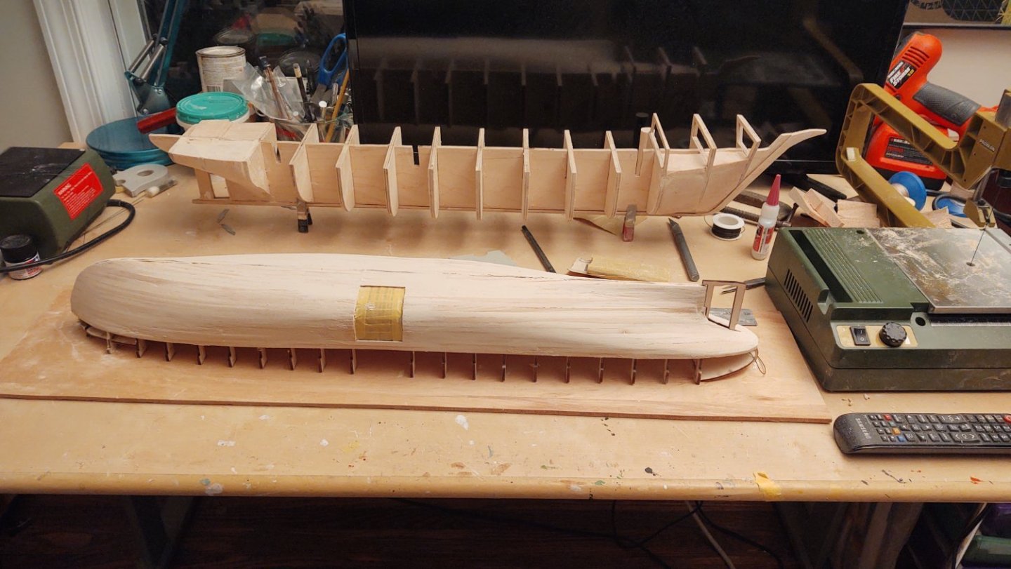
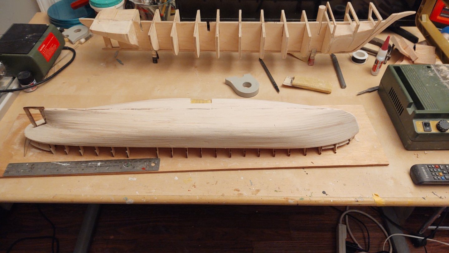
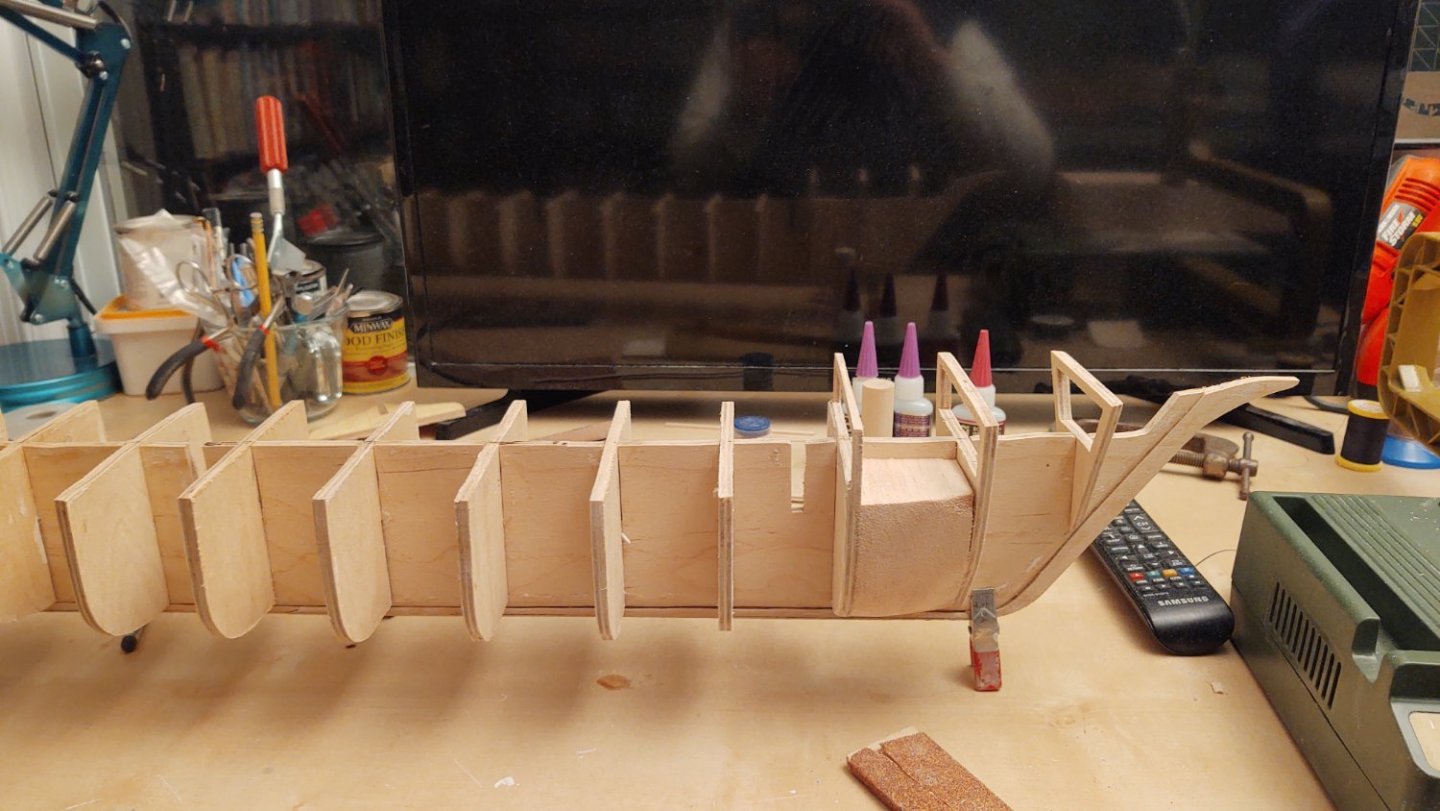
Thanks Rick! Moving along slowly though... The ship as she appears now: The bow filler blocks are in place, as are the stern blocks with the exception of the starboard side block after frame 14. The last two blocks that shape the stern were made from a 2"x3" piece of basswood that I bought at the local hobby shop. It is the hardest piece of bass I have ever seen. My saber saw could barely cut the blank out. I wore out three sanding drums on my Dremel getting it to shape, plus an entire sheet of 100 grit sandpaper. It was so hard, the sanding drum was sometimes burning rather than sanding. I'm frankly wondering if they were making a joke and gave me a chunk of hard maple labelled as bass. I also build out the knightheads and installed them on the bow. They were made from a couple of pieces of spare bass I had from another project and they trimmed much more easily. They are too high right now - once I have the planks that define the forecastle, I'll trim them down to size. Either way, 1 more chunk, some finishing sanding, and it's time for the waterways, which, at least I have a plan for. Thanks for looking in! Regards, George

-
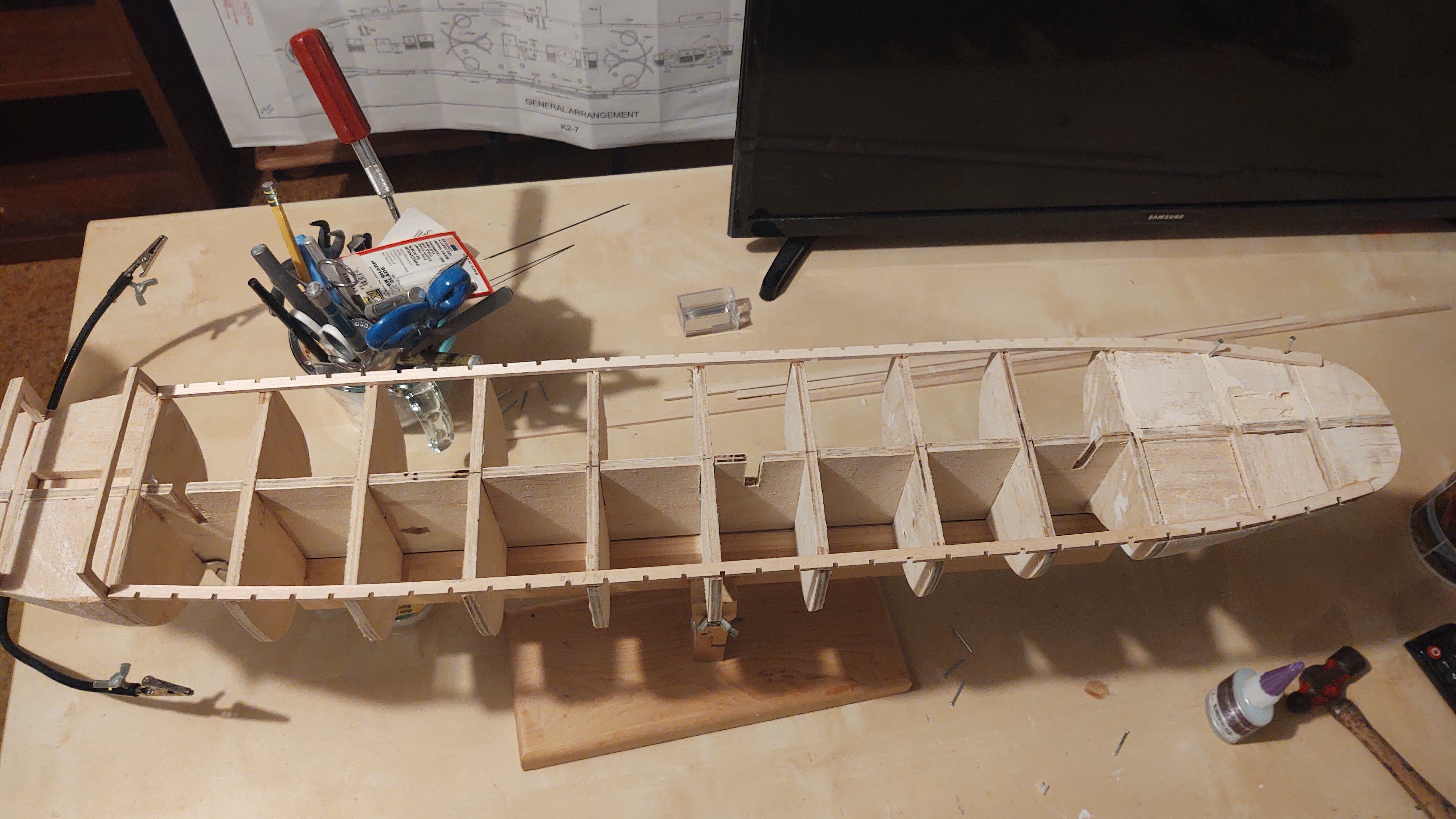
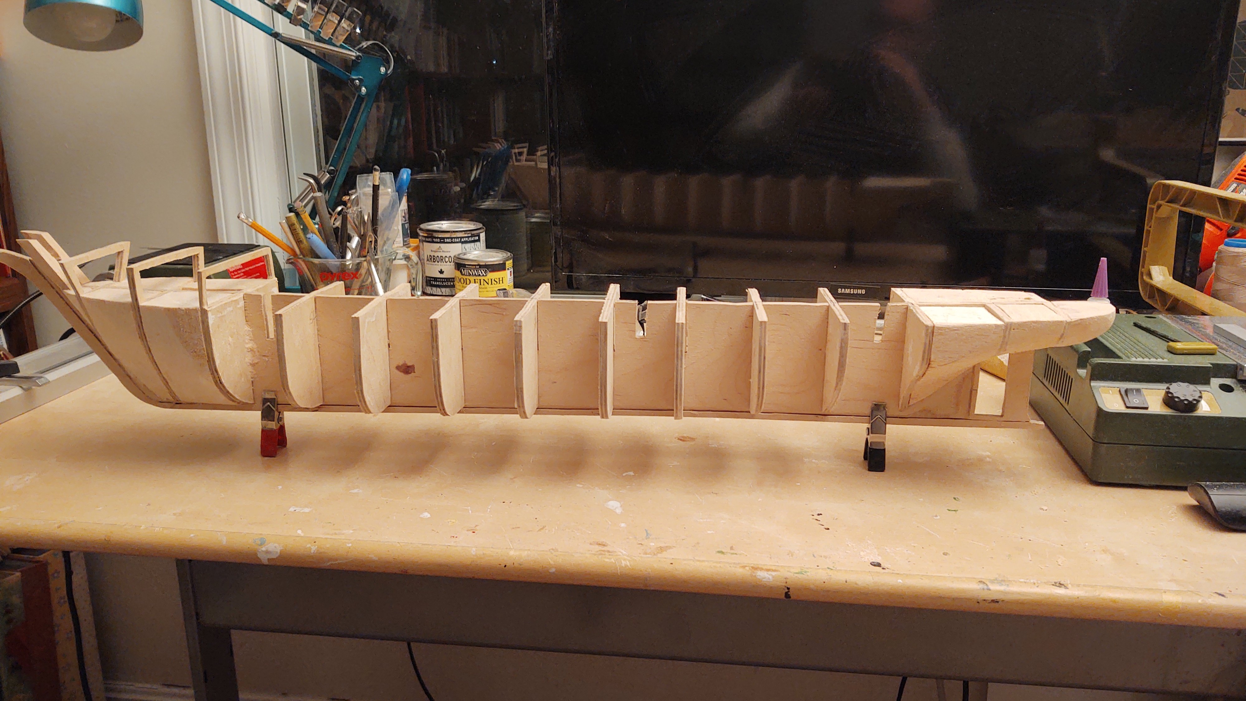
It's been a while, as I've been working on the Discovery and had some travel in there as well. However, I've built up two of the three layers of the bulwarks and continued the preparation of the hull surface. Here are things as they stand (port and starboard) minus the innermost layer of the bulwarks. And from above: I did a dry fit of the decks and while they will need a bit of trimming, I think I'm in a pretty good place there too: In general, I think it looks pretty good, and after some additional sanding and puttying should probably leave me with a good base to copper and paint. I've progressed far enough to start to have some opinions about the kit. First, the good. I can't fault the materials. The wood has been good, the laser cutting sharp and clean, the brass, castings, and resin parts look nice and clean. That said, this is not the way I would have designed the kit. That doesn't make it wrong, but I have found a bunch of the steps in this kit to be really awkward. Compared to having the keel in place from the beginning with a nicely carved rabbet to accept the ends of the planks, I have found this to be very difficult. Similarly, building the bulwark core as a separate piece that you have to glue to a relatively narrow (1/16 x 1/16) "L" shape formed by multiple pieces of wood is much more difficult than forming the bulwark from an extension of the bulkheads, and planking both sides. In addition, you may have noticed that the ship is no longer upside down on the building board - this is because it was virtually impossible to fit the large bulwark core in place with it upside down and glued, and in the process of bullying it in place, I accidentally broke the ship loose. At that point, I said to heck with it, and finished it right side up which I found much easier. FWIW, in common with some of the other build logs I've seen on this ship, it seems to me that the instructions are a bit incomplete. I gather that there is a separate CD with a lot of very helpful build images at additional cost. At the moment, it seems to me that the balance between those that are in the instructions and on the CD is off. This isn't a free kit, and while I absolutely get that this kit is expensive to produce, throwing in some more pictures would probably improve the build experience. And to be fair, it's possible that this design works better when everything is perfect, and I'm far from a perfect builder. It's also true that this just isn't the way I'm used to building, and who knows - I might have felt different if this was my fourth go with this method rather than my first. And I think it's going to eventually build to a really nice looking ship. It definitely deserves the 'Admiral' level, though. If I had tried this three ships back, I probably would have put it aside and moved away from wooden ship building. As always, thanks for looking in! Regards, George


-
I wonder if this will prompt calls to have tugs nearby when any ship goes under some of these crucial bridges. MV Dali was registered at 116,000 DWT and was almost as tall as the bridge itself, nothing like the ships that were being used (or even considered) when the bridge was being designed and built. It's not even clear to me what exactly how you would engineer against a quarter of a billion pounds of anything striking a pier.
-
Thanks Rick! So, completed the coarse preparation of the main hull, a bit of putty and some 150 grit sandpaper. It will need more, but I think it's good enough to start putting the inner bulwark pieces in. Once they are planked, I can do a much better job getting the hull ready for paint. The really good news is that I am going to copper the bottom rather than paint it, so any imperfections will be even more hidden. In the photos below (with the frame for the RRS Discovery in the background), I've dry fitted the rudder post, it will come out before the next step. So, starboard side: and port side: One observation. I went looking for the relevant pieces for the inner bulwark. The two main pieces were easy to spot. They are LK72(A) and there are two of them. The pieces for the stern are LK72(B) and there are 4. What surprised me was that, on the same sheet, right next to LK72(A) were 4 pieces marked LK27(B), and I couldn't figure out how the heck I was supposed to use them to build the stern. Of course, they were the wrong pieces (I had swapped two digits) and when I saw the actual LK72(B)'s (which are half the thickness and hence on a different sheet), the whole thing made sense. With that said, if BlueJacket ever revises the instructions, they might consider including a diagram or photo of how these pieces work. Thanks for looking in and for the likes! George
-
Beautiful work!
-
Well, @MrBlueJacket's adage that "putty and paint make it look what it ain't" seems to be starting to come true. I've put the four starboard side balsa inserts in and faired them. The aftmost is going to be made from basswood since it is going to define the stern's curve. At this point I need to go to the hobby shop and get some more balsa, that chunk didn't go quite as far as I expected. But starting to look like a ship. Thanks for looking in! Regards, George
-
The mizzen has only a spider band, no fife rails, which is consistent with a lot of other ships I've seen. I'm not sure how I would interpret the spider bands on the fore and main (they are both there, BTW). The original builder's plans show the fore and main fife rails and no fife rail on the mizzen, so I'm confident Discovery had them from the beginning. The ship didn't carry that much canvas in 1901, so why they would need both is a mystery to me. That said, the current ship's rigging is vastly different than during the 1901-1904 time period, though. The fore and mainmasts were moved 4 and 8 feet forward to their current locations in 1923; the current ship carries 5 yards/square rigged mast (vs. 4 in 1901), the bowsprit now has a jibboom that wasn't there then, etc. Wasn't there in 1901 (possible, looking for photos that would answer the questions)? Belt and suspenders? Maybe the sailors found the spider band more convenient but no one wanted to yank the fife rails? Someplace to anchor the extra lines associated with the split topgallants that were added? Your guess is as good or better than mine. Regards, GAK
- 206 replies
-
- 1
-
-
- Endurance
- Shackleton
- (and 2 more)
-
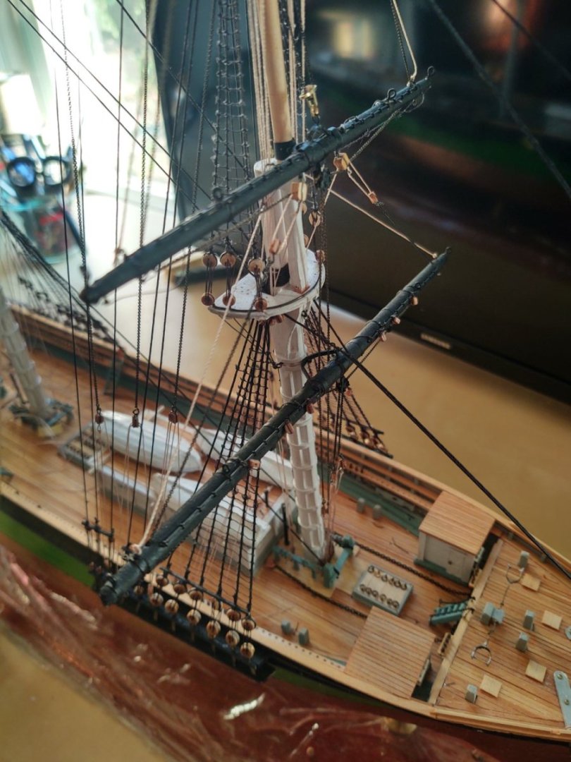
Hi Tom, Ship is looking great. This was like 8 weeks ago, but I'm interested here because I'm doing a scratch build of RRS Discovery and I have the same issue in that the plans I have are good for the standing rigging, and the location of the running rigging on the masts/yards, how they are anchored isn't shown. I am going to see if there are other plans at the Maritime Museum (I only had a couple scanned b/c it was expensive) but will let you know what I learn about how Discovery was rigged if you are interested. Two thoughts. First, as to the sheet's and halyards that are nominally tied to an eyebolt surrounding the masts, that seems odd to me. For the square rigged mast in particular, I would expect a ring of eyebolts that was the deck location of the tackles that go to the sheets/halyards/live lifts, but the live end of the tackle would end at a pin on a fife rail or on the mast. That is how the Flying Fish is rigged (see photo below). Not the best photo, but you can see the tackle that is attached to the sheet chains. Discovery is rigged the same way. You can see the tackles and the live ends on the fife rail of the foremast. Now, you need to be careful over interpreting - Discovery had her rig changed many times over the years (heck the masts were physically moved in the '20s, but when I see this pattern over a span of 50 years I suspect it's pretty common. I've never heard of anything running attaching to the channels either. Again, I've seen examples of tackles being attached to the channels (e.g. royal and skysail halyards) with the live ends of the tackle attached to a pin on a pinrail on the inside bullwarks. FWIW, Discovery has a continuous pinrail that runs along the length of the bulwarks, with periodic holes for pins. My suspicion is that lines that were belayed at the bulwark were belayed where convenient and not according to some unalterable master plan. Regards, George
- 206 replies
-
- 1
-
-
- Endurance
- Shackleton
- (and 2 more)
-
My local hobby shop nominally carries a pretty wide selection of basswood strip (Midwest is their supplier), but their actual stock is a bit sketchier. I was there over the weekend to buy some glue, and I figured I'd get the 1/8" x 1/4" wood I'd need for the waterways, but they had none available. I generally try to buy from local sources (this place is a 3 location local chain in the DC area) to help keep them viable, or at least buy from specialist online retailers that support ship modelers for the same reason. Maybe they can order what I need for me.
-
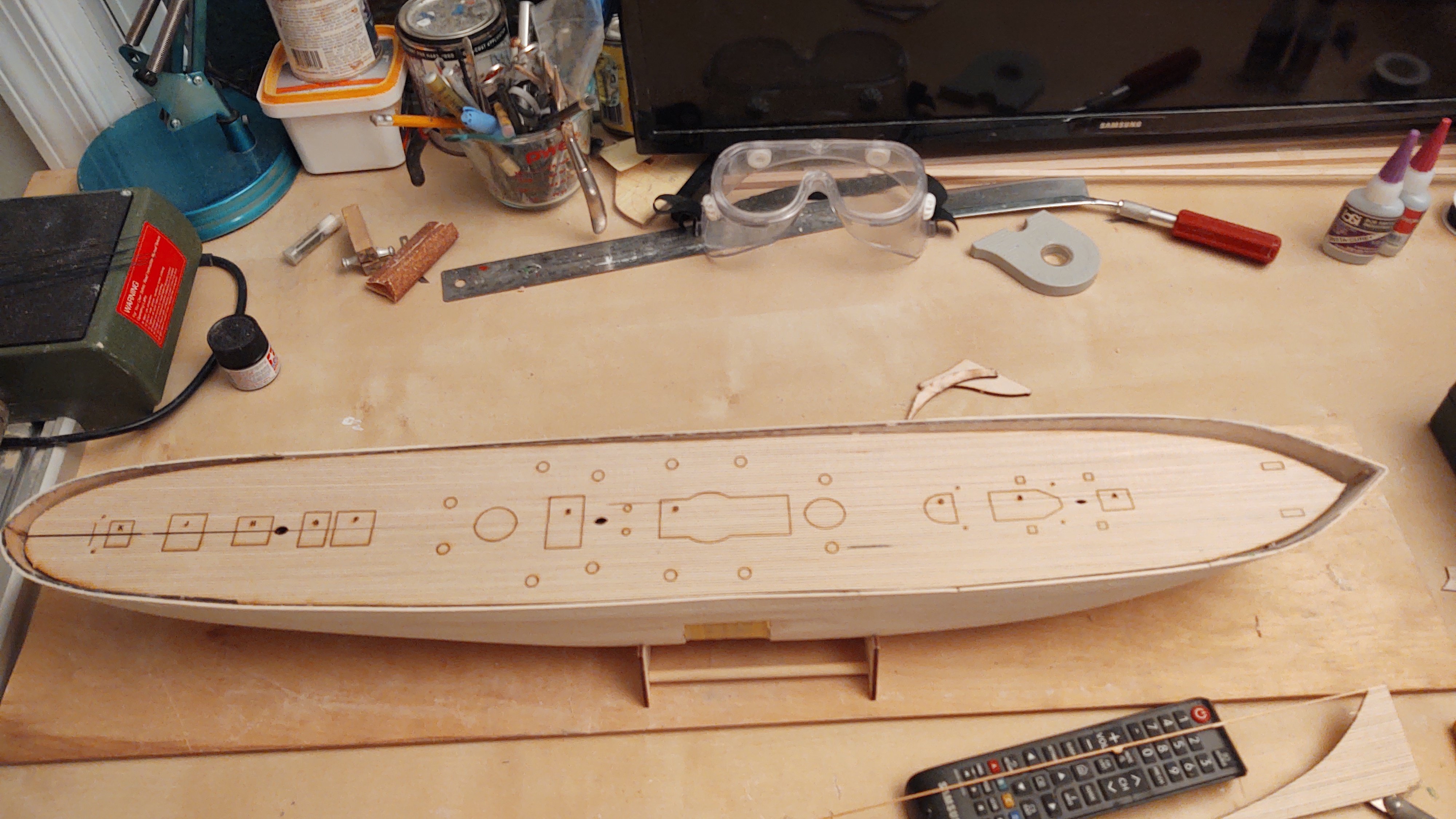
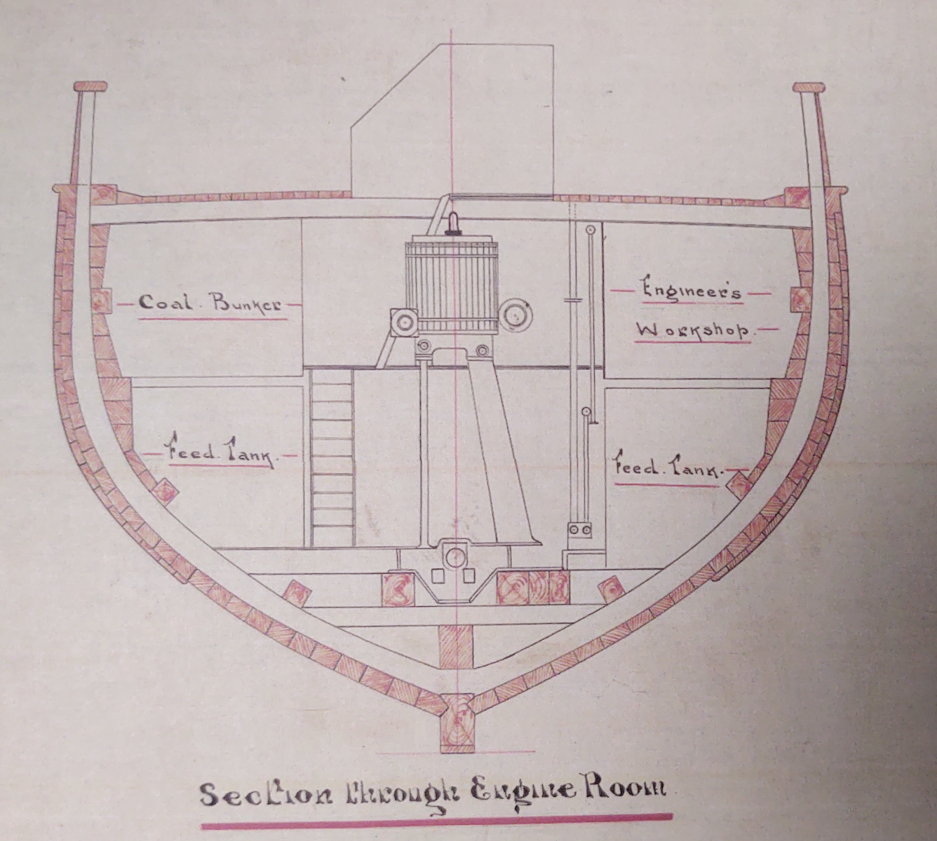
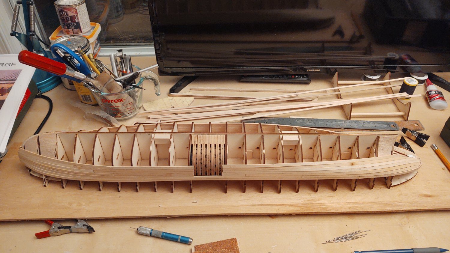
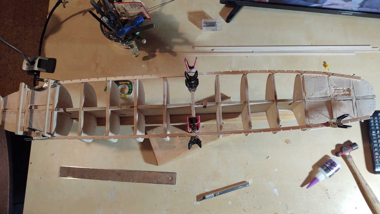
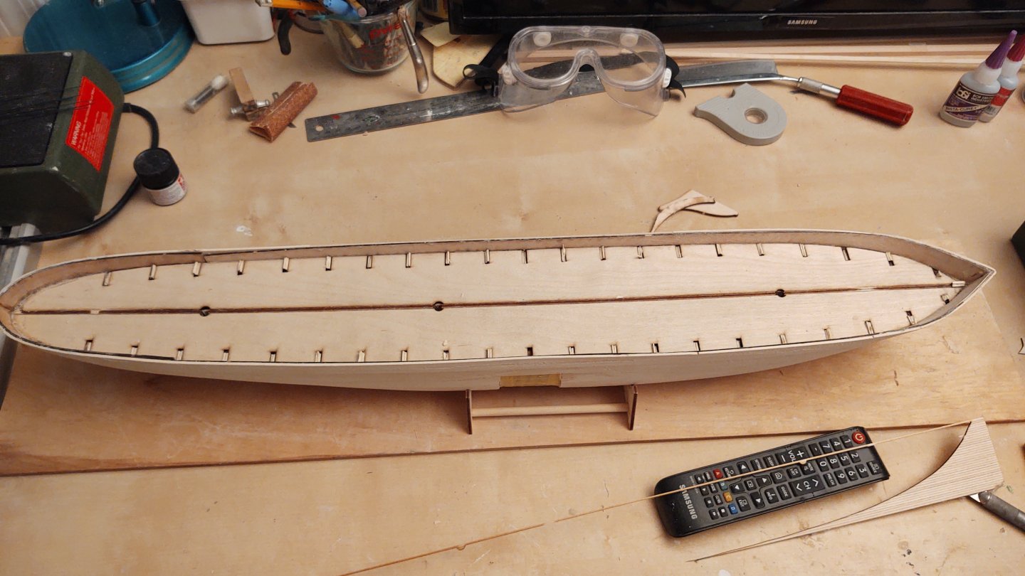
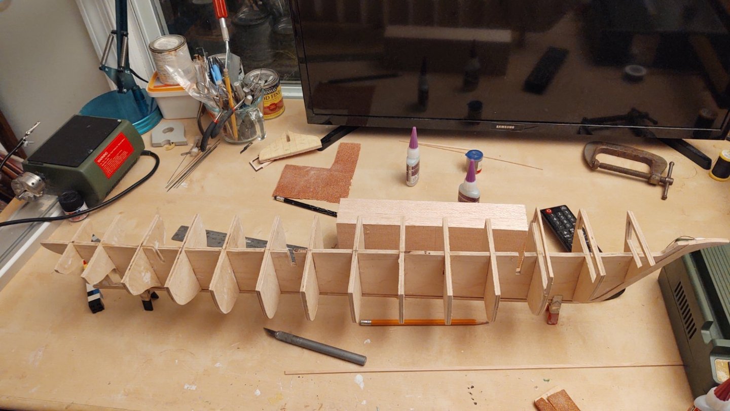
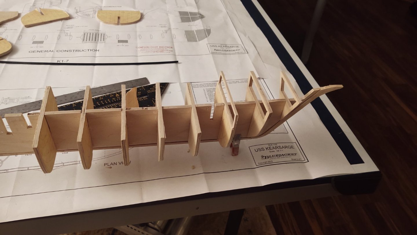
Yikes, it's been about 3 weeks since I posted an update. Part of that time I was away, and part of it was working on the USS Kearsarge, but some real progress. First photo, all of the frames are fared, their elevations evened out, and glued in place. Large chunk of extra balsa from the Kearsarge in the background about to become part of the ship. Second photo has the first of the filler blocks in place and (mostly) faired (final fairing needs all the fillers). It doesn't go to the top of the bulkhead at this moment because I'm trying to efficiently use the balsa block I have handy - I'll fill the rest in with leftover chunks. I'm imaging 8 or 10 balsa fillers at the moment (between bulkheads 2-4 and either 11 or 12 to 14. From 14 to the stern I'm going to make the filler blocks out of basswood, and for the prow to bulkhead 1, I'm going to make a basswood filler that includes the knightheads. The ship gets two sets of planking (as seen in the section below). The inner, thicker set where the planks average out to about 2mm (1/16 to 3/32") deep by 3mm about (1/8") tall at scale, although the actual thicknesses vary a bit, and an outer layer over about 2/3 of the hull that is about 1mm x 3mm at scale. The model will be pained, so, presumably I'll use basswood - it's cheap(er), it bends well, and it doesn't have to have beautiful color or grain. That said, can anyone recommend a wood source? The only sources I know of with small dimensional lumber are ModelExpo and BlueJacket. Do you all find one superior to the other? Is there someplace else people would suggest? Any input appreciated. I'm on the US East Coast if that matters. As always, thanks for the likes and for looking in. Regards, George

-
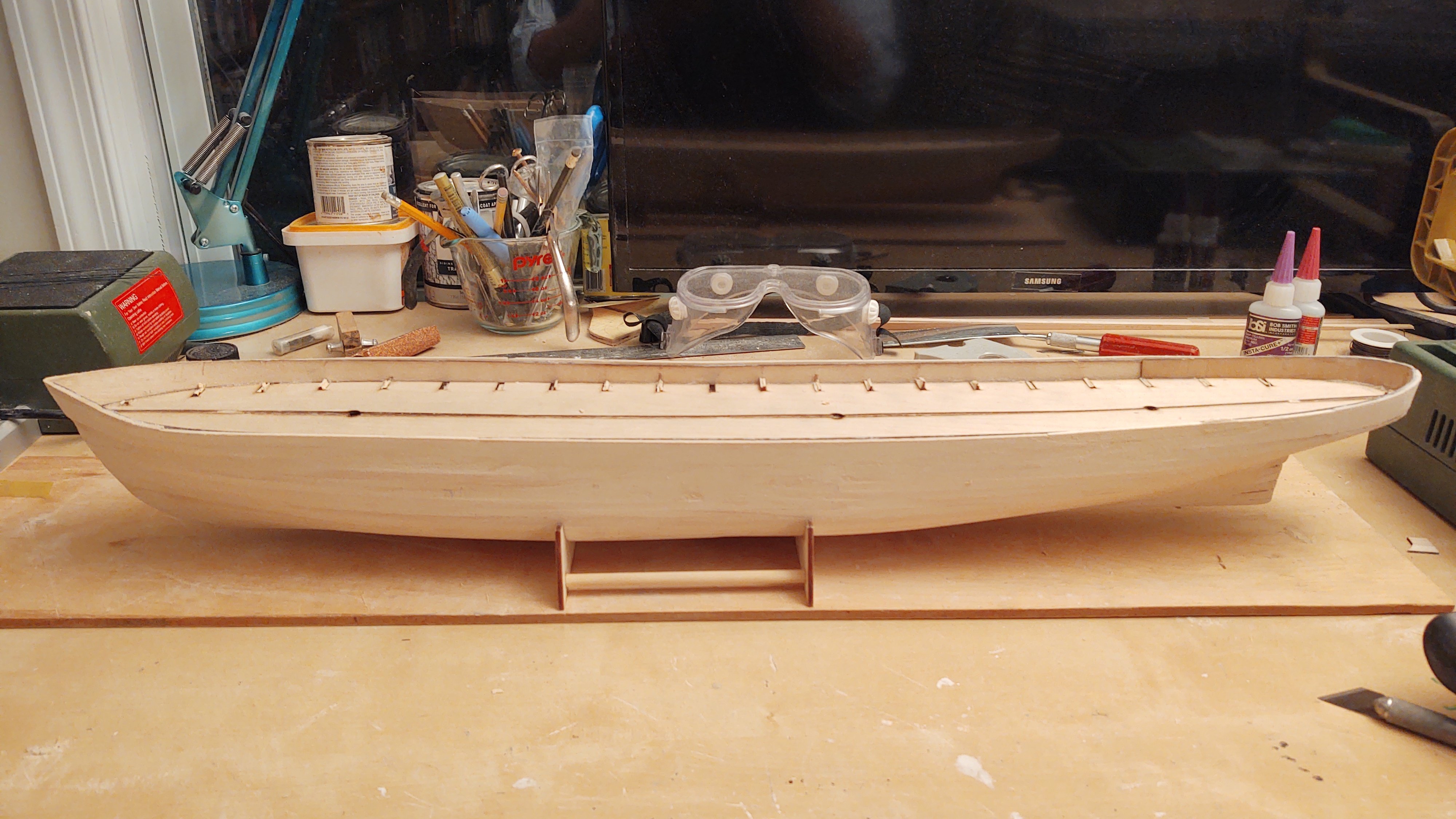
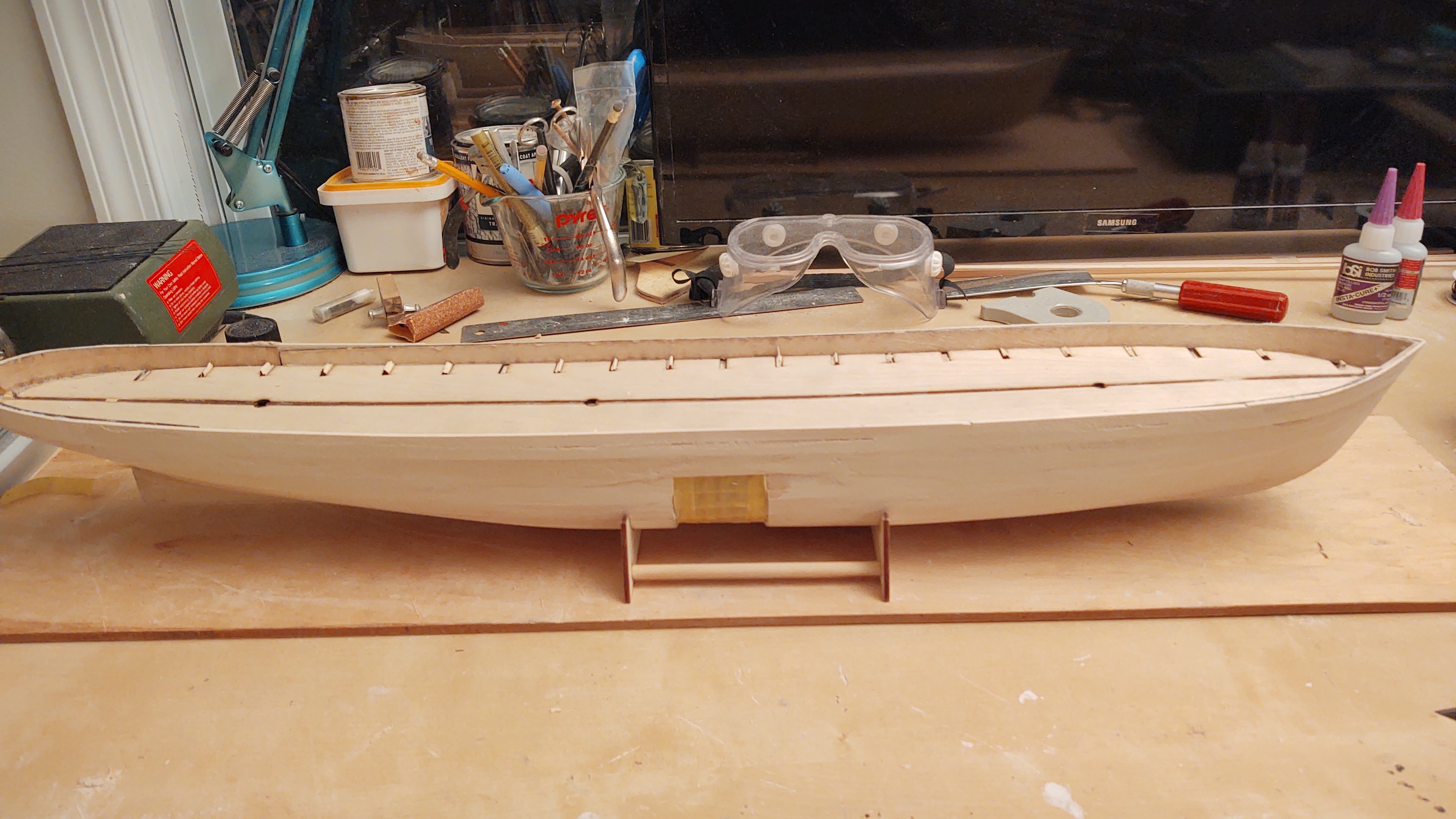
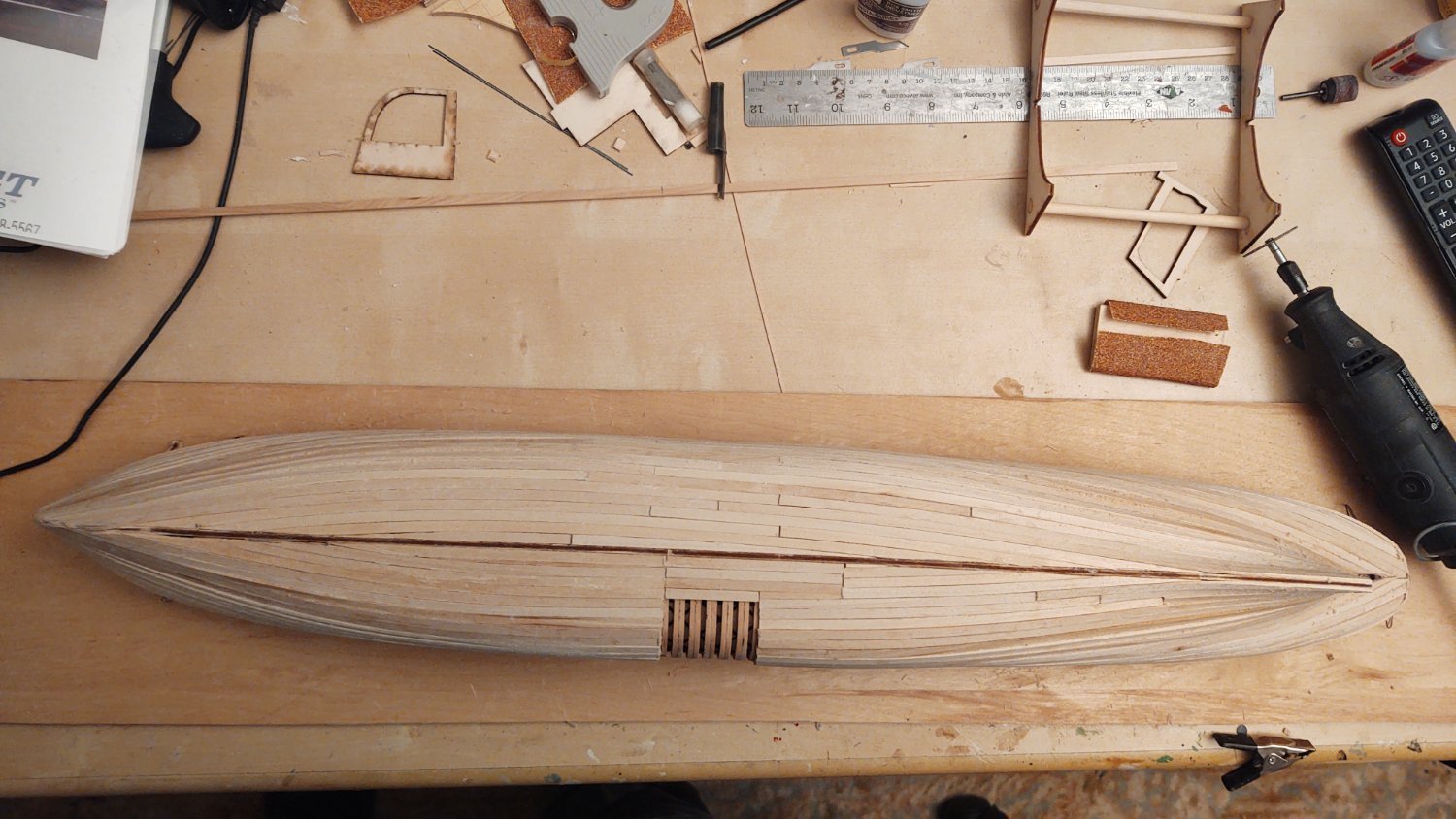
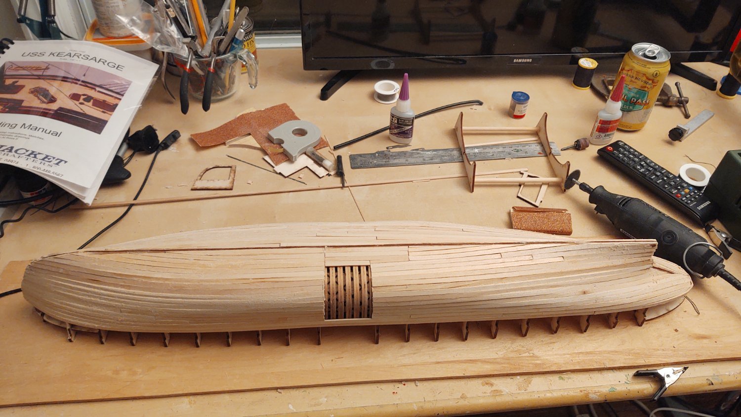
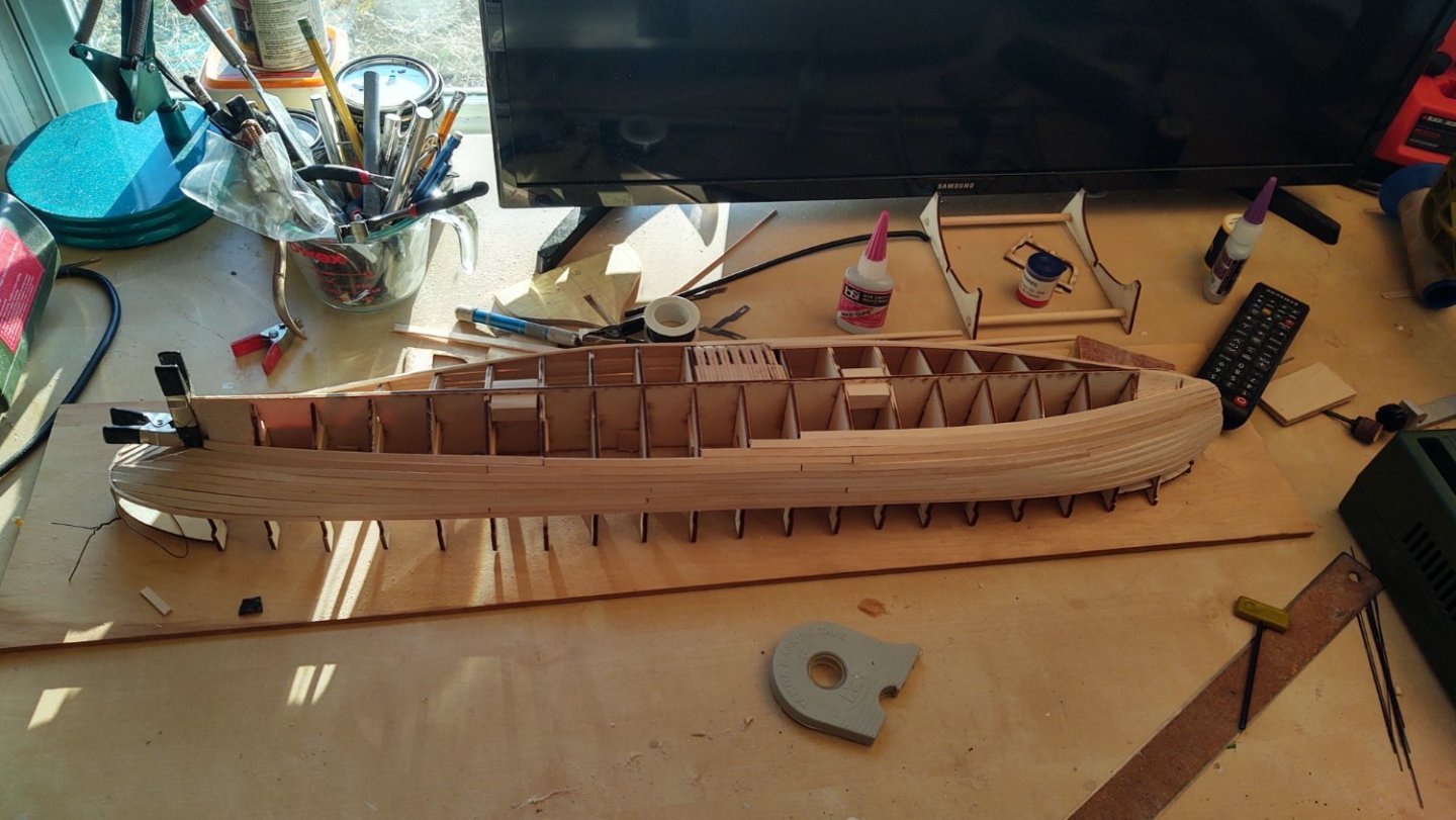
A brief update. The basic planking is completed. It needs some filler and sanding now, before I move on to the bulwarks. Thanks for looking in! Regards, George


-
FWIW, I used 24 gauge annealed steel wire for the jackstays on my 1:96 Flying Fish, except on the skysails where I dropped to 34 gauge. Doesn't mean it's right or to scale, but it seemed to look okay and worked tolerably well with the 0.75 x 6mm eyebolts I used for the jackstay eyebolts. Regards, George
-
Mike, Glad you are back. I described what I did in this post: The summary is that I ran the forestays through the relevant locations (bees or hole in the jibboom) and the dolphin striker (if relevant) and then fed it through a hole I drilled in the bulwarks. At each location where the lines changed direction, I put a drop of CA glue to hold it in place, so that by the time I got to the hole in the bulwarks it would stay taut without having major strain on that one drop of glue (the line had 2 or 3 glue drops holding it in place. My recollection is that I ran enough line through the hole that I could snag it with a tweezer and hold it tight while the CA set (maybe 30 seconds). It worked for me, buy YMMV. Hope this helps, George
-
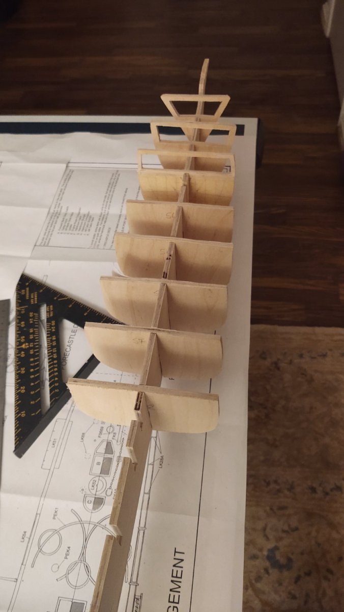
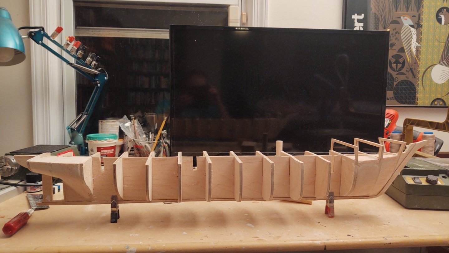
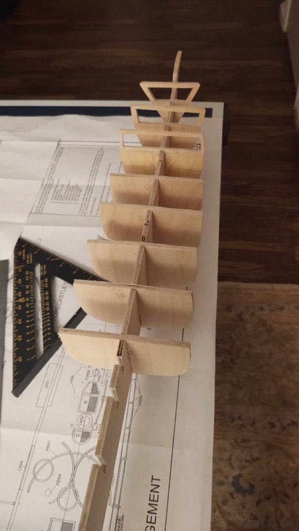
Thanks Keith, appreciate the confidence! I'm heading off on a work trip followed by visit to my daughter in Boise, so last update for a couple of weeks most likely. Bulkheads 1-8 are rough faired, evened out, but not yet glued in place. As you can see I opened out the fo'c'sle after all. I don't anticipate adding ceiling planks in there but the foremast has a set of forestays that anchor in there (through holes in the bulkhead so I just cut them out. One thing that may not be obvious is that in bulkhead 3 I thinned the part above the center keel to 1/8". The reason is that the fo'c'sle starts about 1 ft ahead of the station line in the drawings, so I needed to adjust accordingly. As always, thanks for looking in! Regards, George
-
Thanks Rick! I'm heading off on a work trip followed by visit to my daughter in Boise, so last update for a couple of weeks. Not a ton to report. Hull planking continues, should be finished by the next update. As always, thanks for looking in. Regards, George
-
Planking continues. As with my other project, need to keep reminding myself that putty and sandpaper cover a multitude of sins. Found another stash of 1/16 x 3/16, so going to keep using them until I run out. Thanks for looking in! George

-
Small update. Rabbets are cut. Keel is attached (it currently sticks out a bit on the end. Started fairing the bulkheads. Need to remind myself that putty covers a multitude of sins. Thanks for looking in! Regards, George