gak1965
-
Posts
725 -
Joined
-
Last visited
Content Type
Profiles
Forums
Gallery
Events
Everything posted by gak1965
-
 Sails look great! I hadn't thought about how the split topsail would create a situation where you have stuns'l booms on the course and upper topsail only (so skipping a yard) but that makes complete sense seeing it. What is that device in the background of a bunch of your pics (the one with the 4 meters)? An old school power supply or an amp of some kind? Great work, looks like you will be able to put 'FINISHED' into the title soon! George
- 399 replies
-
- 2
-

-
- cutty sark
- revell
- (and 2 more)
-
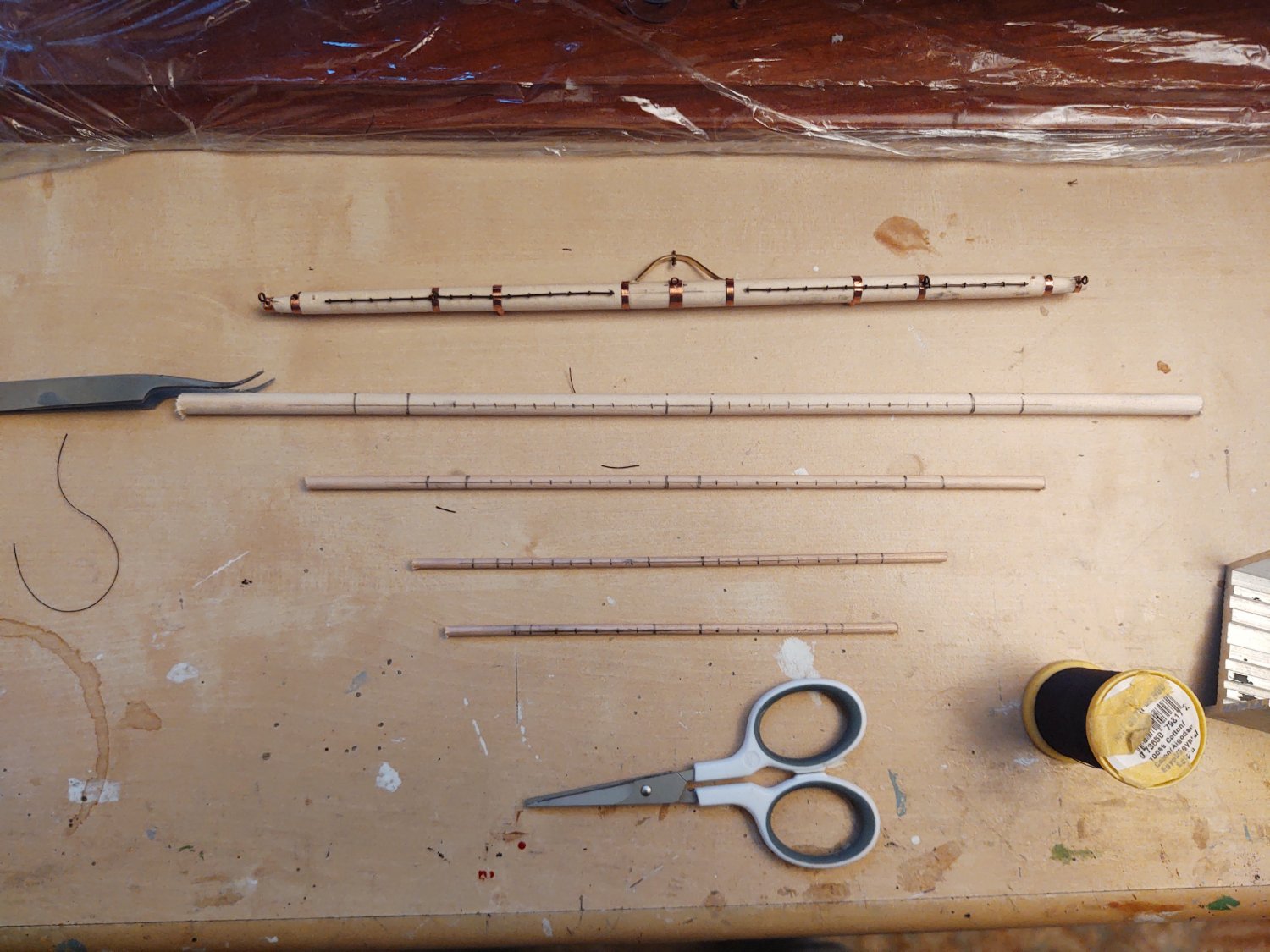
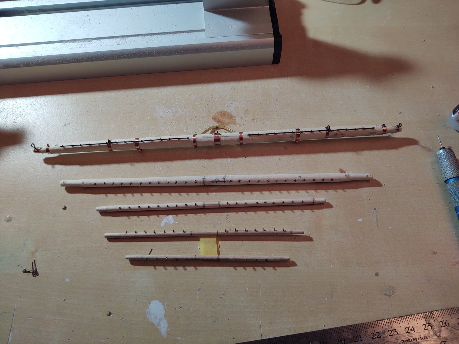
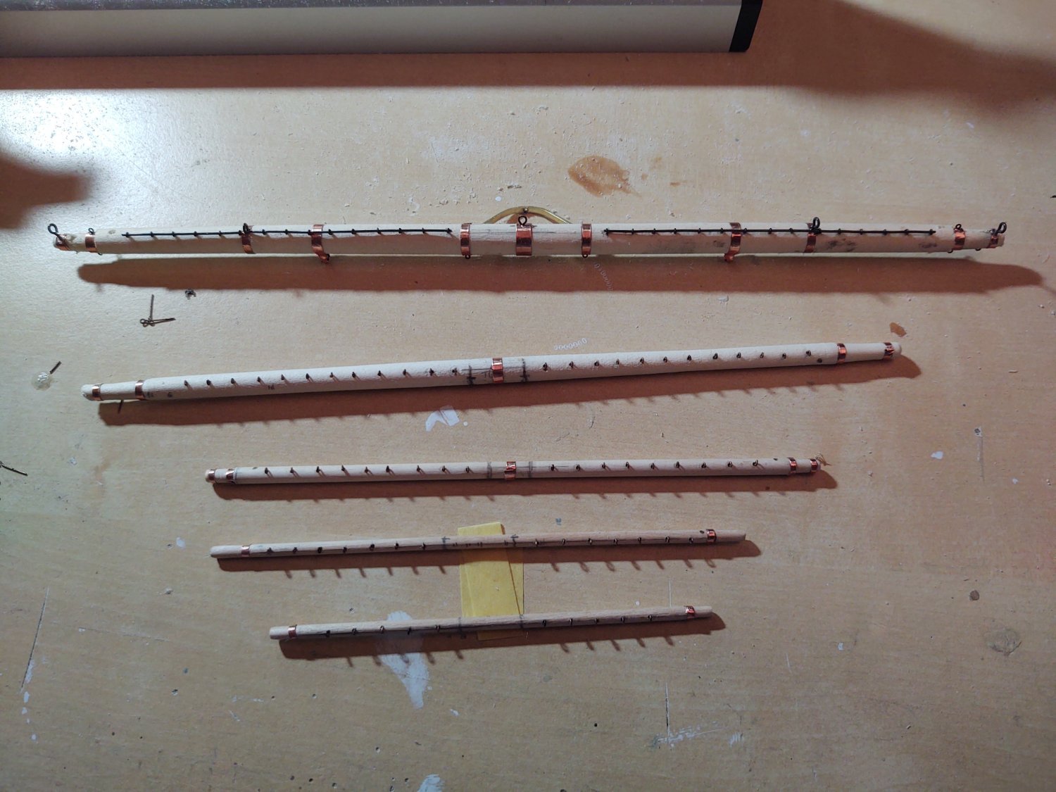
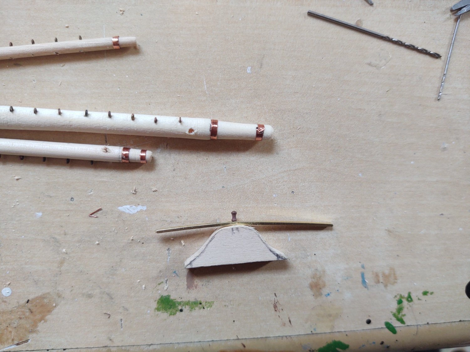
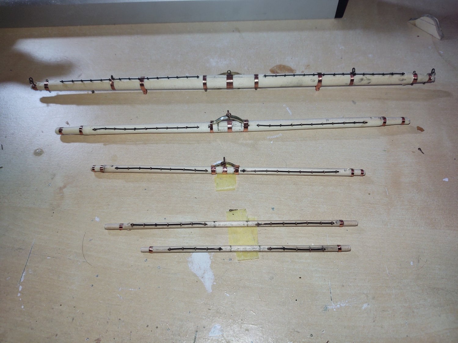
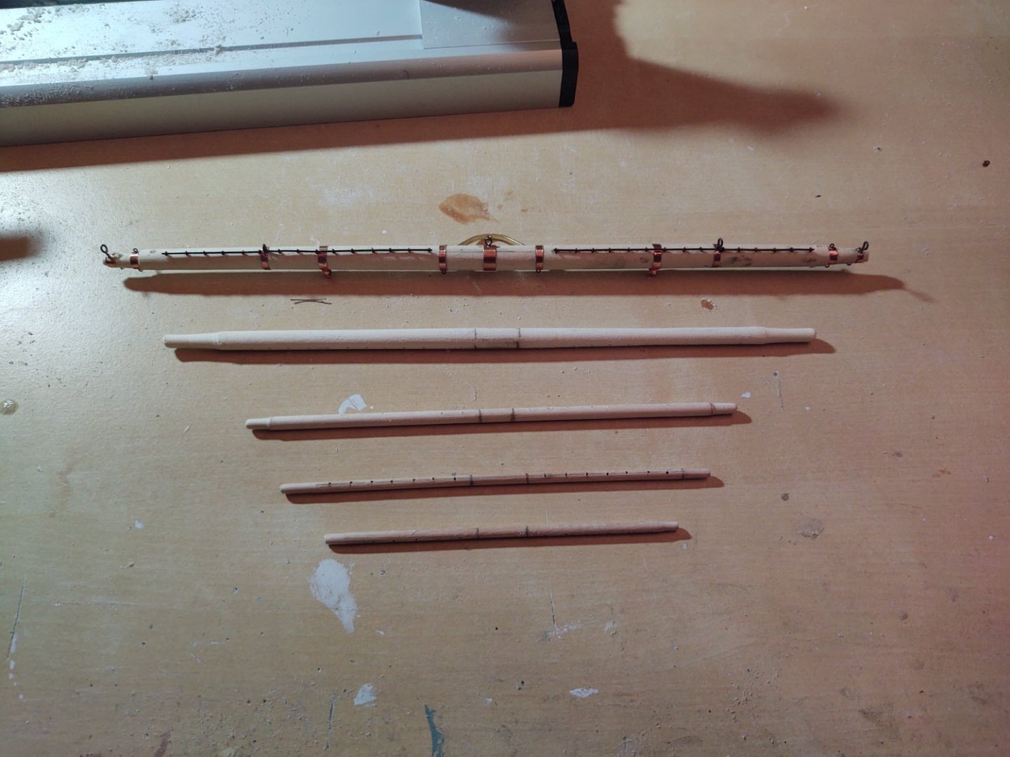
Well, it's been a couple of weeks, so I thought it was time for an update. A little early, but Happy Father's Day to all, and thanks for the well wishes on progress. I mentioned in my last post that I was off to Chicago for the ASCO Annual Meeting, so, I've had more like 9 days rather than 16, but progress is still a bit slow as I find yard making a slow task. However, I've taken a bunch of pics that show the progress of the main yards, including the previously made main course, which I accidentally made with the fore yards. So first, we have a photo of the four dowels that will be the top, topgallant, royal, and sky yards. I've drawn in the locations of the trusses (center) and the yardarms on either side, and then marked where I need to drill the holes for the jackstay eyebolts. Extra wood so they have someplace to attach when I put them in my mini wood lathe. Second photo. Holes drilled and lathed down to shape, with the extra wood cut off. Next step is to put in all of the eyebolts. Photo 4, I've made most of the bands on the yards out of the Venture tape I used to make the copper plating, just cut down to the proper size. Next, I need to make the trusses that connect three of the yards to the masts and are the halyard attachment point on the top yard. I made a former out of a block of wood. I use 1/32 by 1/16 brass strip that I've cut a hole in to make the truss. The hole is the diameter of a belaying pin, so I use that to place the brass onto a forming model I made from a chunk of wood. I bend it with the end of a pair of heavy wire cutters, and then cut the ends to length, and bend them to form the attachment points. If the truss is going to connect the yard to the mast, I take the belaying pin out, remove the 'ball' top, and reinsert it in the other direction, and CA glue it in place. That pin will eventually be mounted in a hole in the mast to allow me to sturdily set the yard in place. It won't allow me to change the orientation (straight on or nothing), but it's very solid, which I appreciate. Finally, the last steps up to where I am now. CA glue the trusses in place, and the wrap with trimmed copper tape. Slide steel wire in the jackstay eyebolts as the jackstay itself. I still need to add a bunch of eyebolts as mounting points for various lines, make and add 2 iron blocks for the course and top yards that handle the top and topgallant sheets, and add the stuns'l irons to the top and topgallant, add the wood parrels to royal and sky, and of course paint them all black, but progress. The jackstays are not perfectly straight, even using my drill press I find that the bit tends to wander a bit, especially on the smaller yards, but once they are painted, it really isn't very noticeable. In any case, thanks for looking in! Regards, George


- 602 replies
-
- 6
-
-
- Flying Fish
- Model Shipways
- (and 2 more)
-
Absolutely concur. The davits are going on the Fish very near the end. The only thing that may go after are the lower stuns'l booms . The holes are drilled (on the Fish they mount on the outside of the hull amidst the chains) but they are getting rigged at the last moment. I'm even tempted to rig them as if the boats are away on a task as the Britannia boats are really bad (the ones on the deck house are upside down and I added some detail to make it look better on the outside).
- 89 replies
-
- 1
-
-
- Cutty Sark
- Revell
- (and 2 more)
-
One other thought is to get a set of Britannia davits from Bluejacket or Model Expo. It looks like BlueJacket has several sizes, and they make 1:96 ships that use them (e.g. Red Jacket), and they will sell definitely you a couple pair even if they aren't in the catalog. I don't see them in the model expo catalog, but my Flying Fish has 4, so they must make them, and I imagine that if you call or email they will sell you some. Britannia fittings are also somewhat soft so you will need to use some care, but they will do better than soft plastic. I'm not in love with the model expo ones generally, as I find they have a lot of flash and sometimes casting defects such that I've replaced a subset of them on my Fish with either Bluejacket or scratch replacements, but I'm not planning on doing that with the davits at the moment. George
- 89 replies
-
- 2
-
-
- Cutty Sark
- Revell
- (and 2 more)
-
The 2017 instructions don't make a lot of sense to me. It looks like they are trying to set up the boats to be lifted out of their cradles, but the rig for that looks all wrong to my eyes. Something I have done to flimsy wood parts is add some wire or brass in unobtrusive locations (like underneath spreaders). Can you take a bit of brass or steel wire, CA glue it to the hidden side of the davit and paint the whole thing? I'm not sure exactly how big these are, but maybe that would work enough to keep things steady. Could you set the spacing between the blocks with the line in place and then paint it with dilute glue while hanging down? It would presumably stiffen the tackle and you could attach it on the other davit without worrying that it will go slack. Never tried it, it's just an idea. George
- 89 replies
-
- 2
-
-
- Cutty Sark
- Revell
- (and 2 more)
-
Can't say for WWII. However, if you go here: https://www.dailypress.com/2019/10/29/the-aircraft-carrier-john-f-kennedy-to-float-in-dry-dock-12-at-newport-news-shipbuilding/ and go to the third picture, you will see that on modern ships at least, the shafts are painted.
- 154 replies
-
- 3
-
-
- Enterprise
- Trumpeter
- (and 1 more)
-
Wow. Six capstans. Is the helm in that aftermost house on the poop? Given the skylights I assume there are some kind of cabins in the after 1/3 of the ship whose overheads make up the poop deck? She must have been a bear to unload with only two hatches, both in the waist. Regards, George K
-
Saratoga and Lexington were repurposed battlecruiser hulls. Under the Washington Naval Treaty, they could be either scrapped or turned into aircraft carriers. Yorktown and Enterprise were designed as carriers from the ground up, and was based on the US Navy's first such clean sheet design, USS Ranger, although both were much bigger than Ranger. Wasp was a smaller ship, more like Ranger because of the available limits under the Washington and London Naval Treaties. After the treaty system was concluded, the Navy built Hornet to the Yorktown specification. George K
- 154 replies
-
- 4
-
-

-
- Enterprise
- Trumpeter
- (and 1 more)
-
Thanks Rick! I did the standing rigging fore to aft, but would do the opposite next time, as you are proposing, mostly because I think that getting the forestays on the mizzen and main will be easier without the shrouds from mast in front of it getting in the way of the anchor points on the next mast forward. However, I'm glad I'm going fore to aft on the yards. Because the majority of the lines end aft of the mast itself, by going fore to aft, I don't have the yards from the main or mizzen getting in the way as I have to reach into the gap between the masts to anchor onto to the pin rails. Your mileage may vary. Once I start installing the main yards, this thesis may be proved wrong, but so far I think it's working George K
-
Hello all! Well, just a quick photo, the foremast is now complete, minus the braces, so a milestone. I will be away from the bench for a week, as I'm going to Chicago for the annual American Society of Clinical Oncology conference. I haven't been since 2019 because of the pandemic and various job changes, so looking forward even though it means being away for a while. As always, thanks for looking in, and for the likes! Regards, George K


- 602 replies
-
- 5
-
-

-
- Flying Fish
- Model Shipways
- (and 2 more)
-
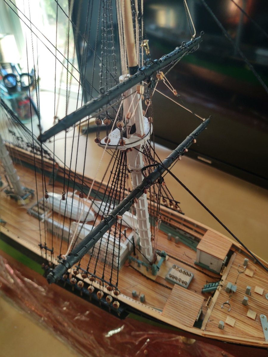
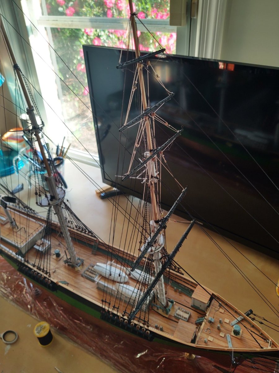
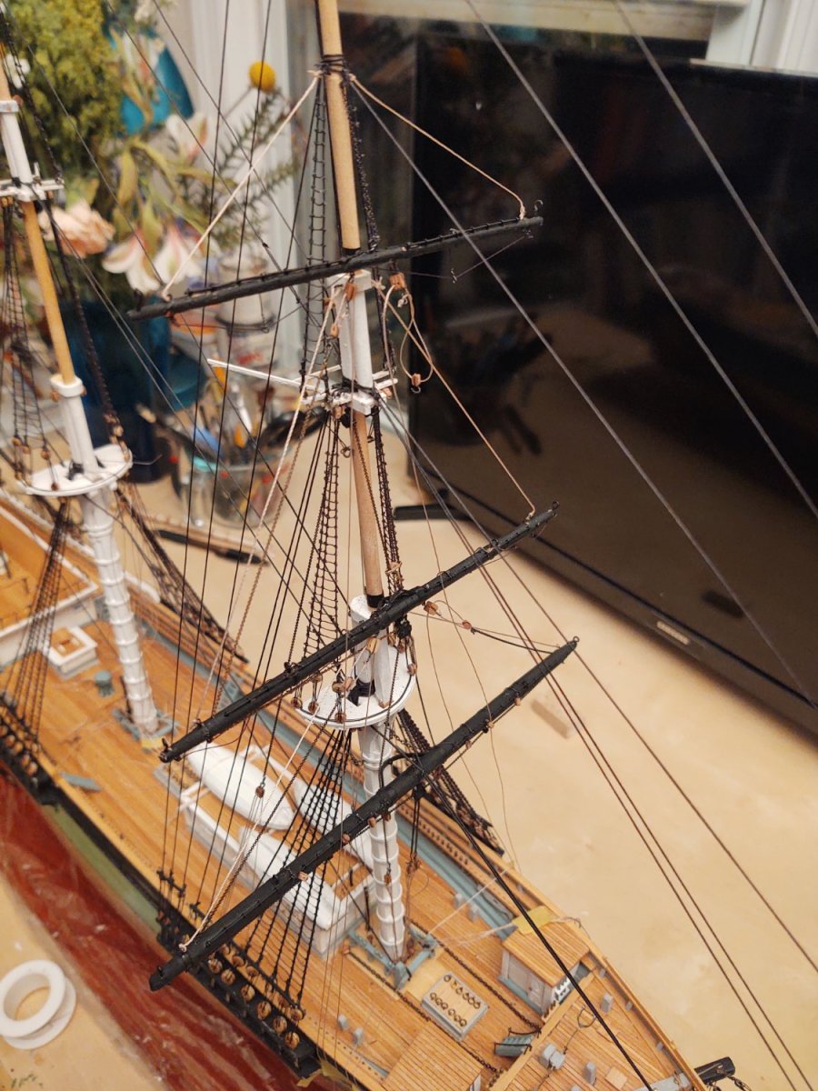
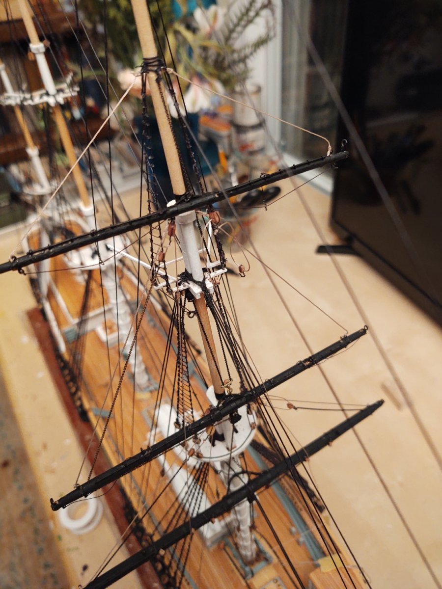
Good evening to all. Memorial Day is a holiday that has many meanings to different people, so I will just say that I hope that all that mark the day found their observance satisfactory. I've been busy on the foremast, which now has all five yards (course, top, topgallant, royal, and sky mounted. All of the halyards are mounted, and the live ends secured. The course lifts are fully in place, as are the iron sheets for the top and topgallants. I mounted five trucks on each set of fore shrouds to act as fairleads so that I can start the clews and sheets that are higher up the mast. The top clews and sheets and topgallant clews and sheets are fully installed, the royal sheets are mounted and threaded through the trucks, and the skysail clews and sheets have yet to be installed. Still progress is being made. Here are some photos: One little oopsie that I discovered was that after installing the topgallant yard, I had failed to drill the sheaves for the sheets. When I went to drill one side, I put enough pressure that it ruined one of the lifts, which required replacement. When I went to do the other side, I was determined not to do so much damage, so I set up the following jig using a bit of dowel, held in place with Tamiya tape. It kept the yard from moving so much and I was able to drill the hole without additional damage. Eagle eyed individuals may also spot a point where I repaired a chain that broke under stress (I basically made another link with very fine wire). I figure that the latter is probably something that happened on the real ship, so, it's a feature, not a bug. As always, thanks for looking in and for the likes! Regards, George K.

- 602 replies
-
- 5
-
-
- Flying Fish
- Model Shipways
- (and 2 more)
-
Those must have been a royal (hah!) Pain to adjust. However you threaded them, it seems like you would have lanyards on top of lanyards, with many of them preventing the set under them from moving...
-
I have nothing to offer on the best way to build her, certainly not compared to some of the folks that have actual expertise. My only observation looking at the side view plan (and where I m in my current build) was "I hope you enjoy tying ratlines", because that ship has a lot of shrouds... Good luck, I'm sure she's going to turn out great! George K
-
The Balaos and Gatos were all designed with having to transit the large distances of the Pacific so that they could operate with the battle fleet. As a result they were designed with certain comforts such as enough racks for each sailor to have their own and lots of food storage. While the nominal range of the Type IXC was longer, it seems like (at least in the beginning) the Germans were anticipating shorter patrols and less need for the creature comforts that took up space in US fleet subs
-
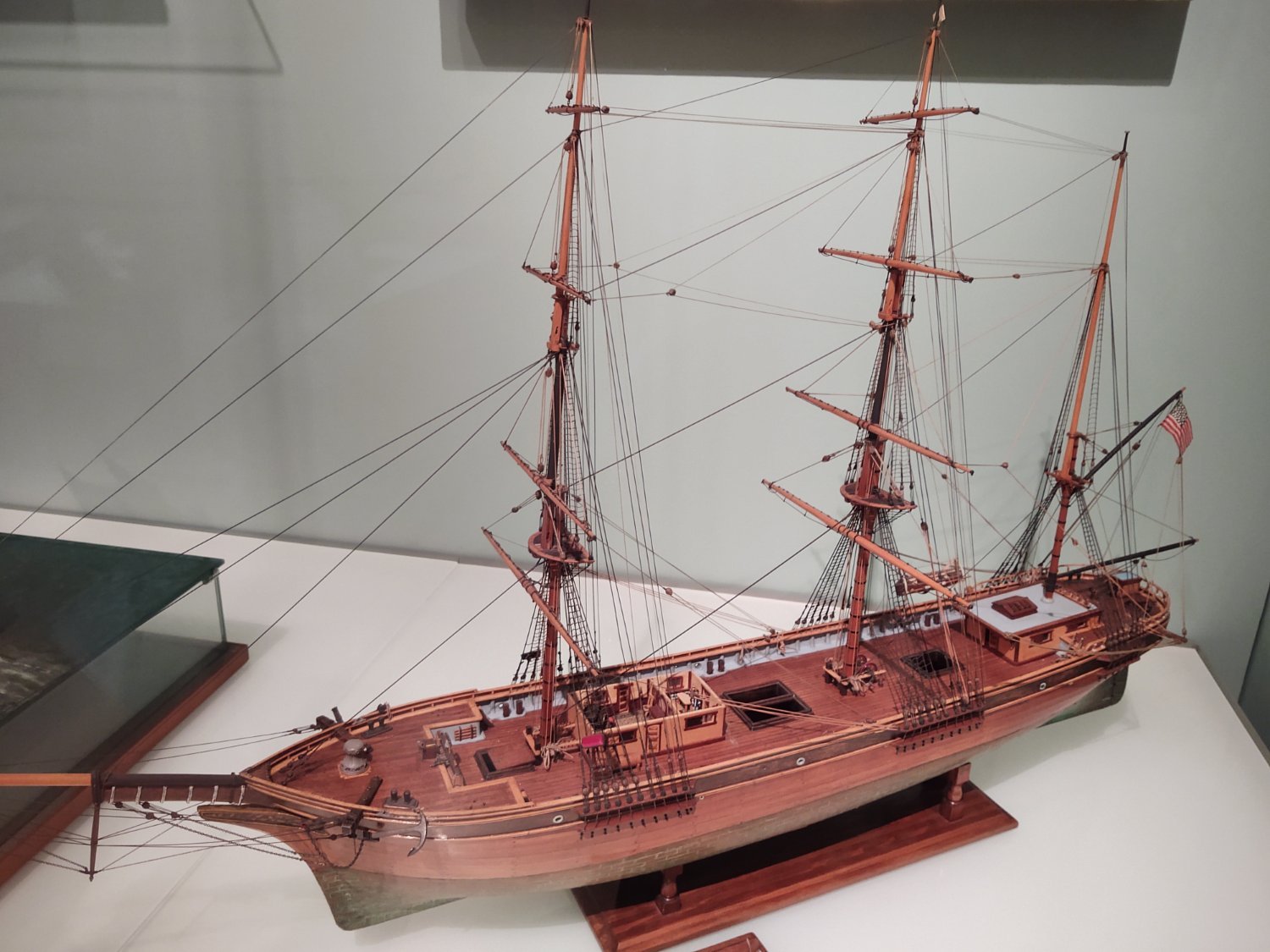
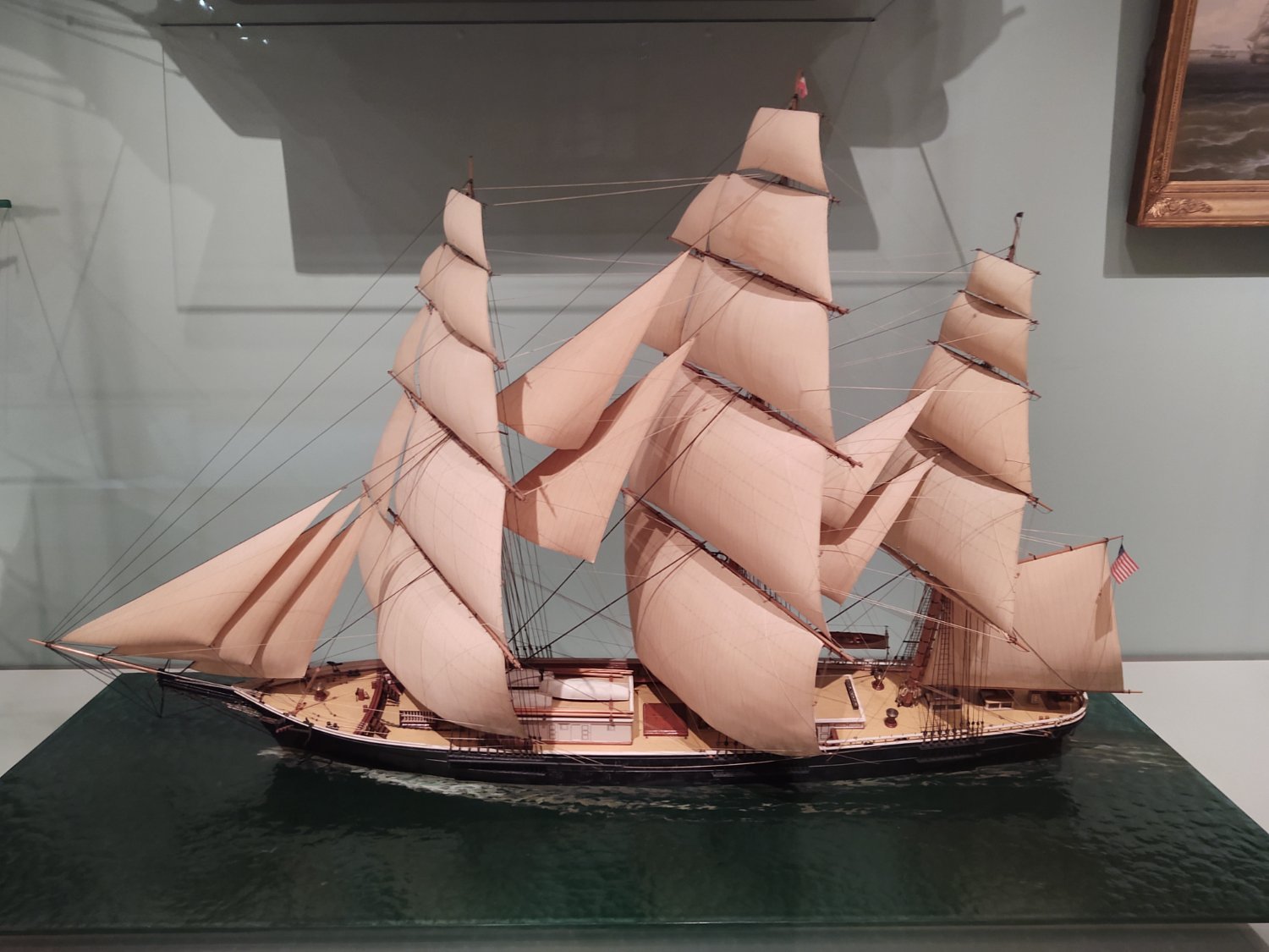
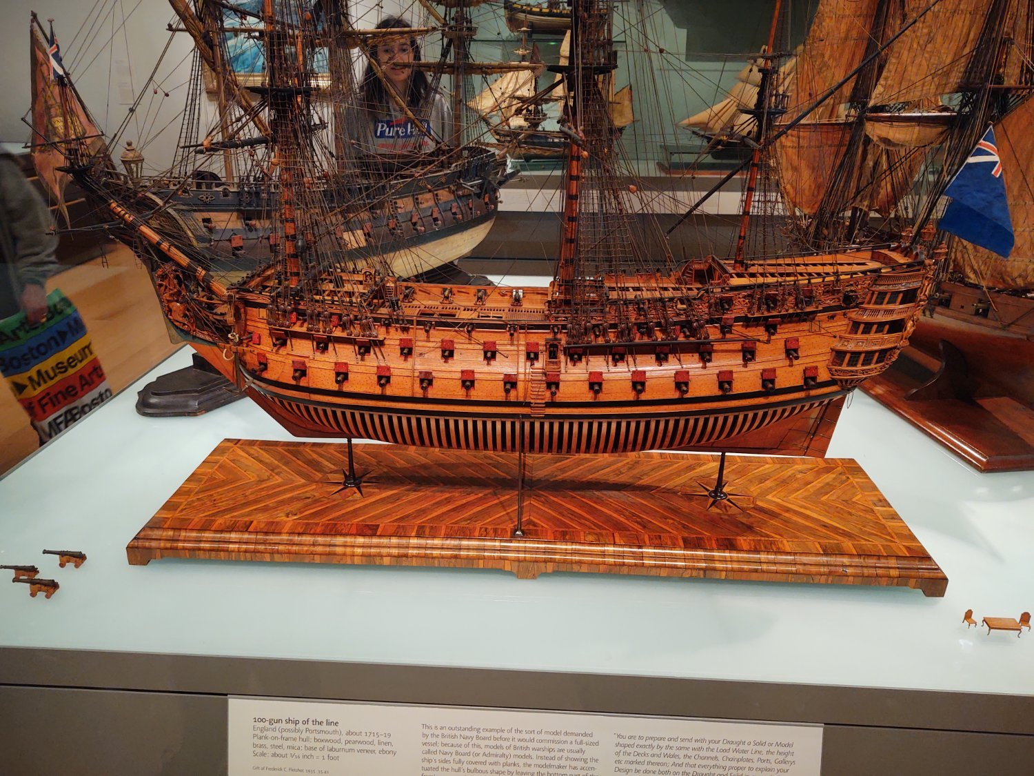
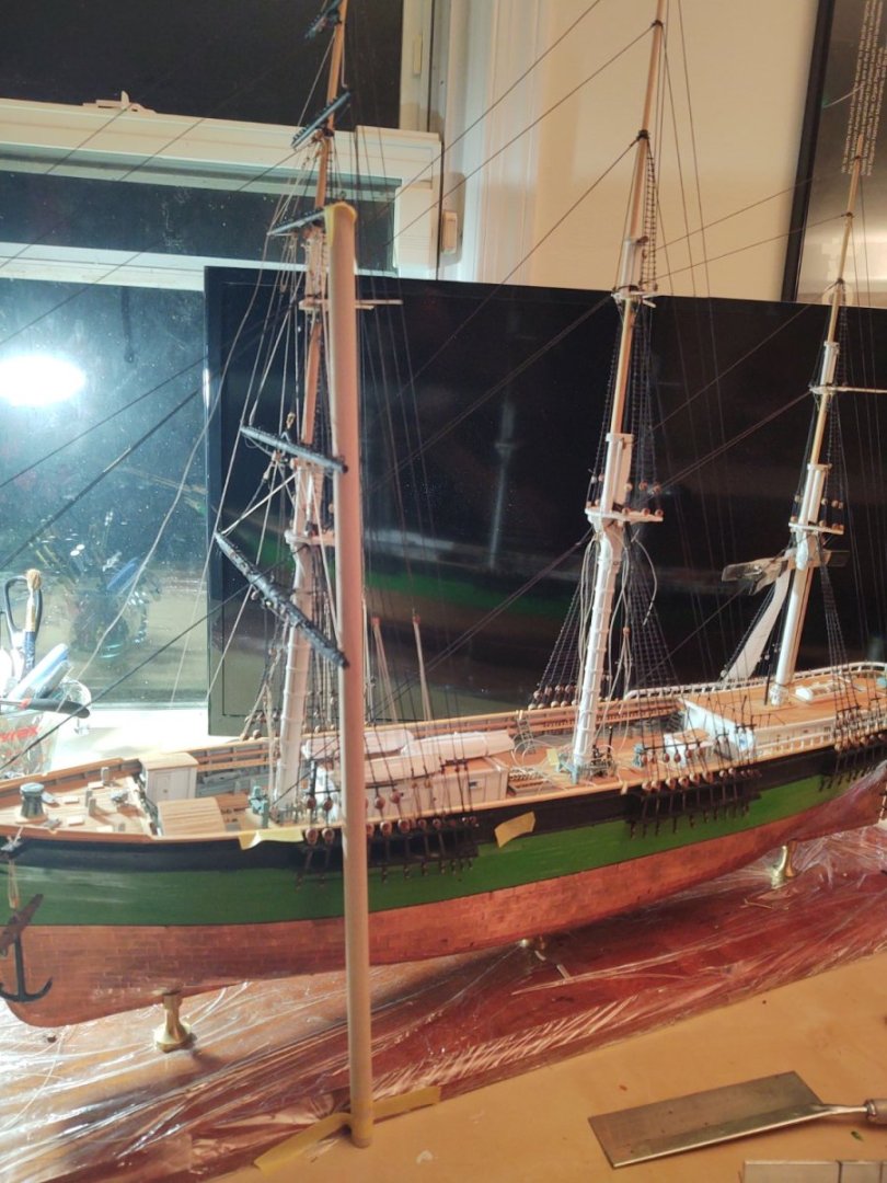
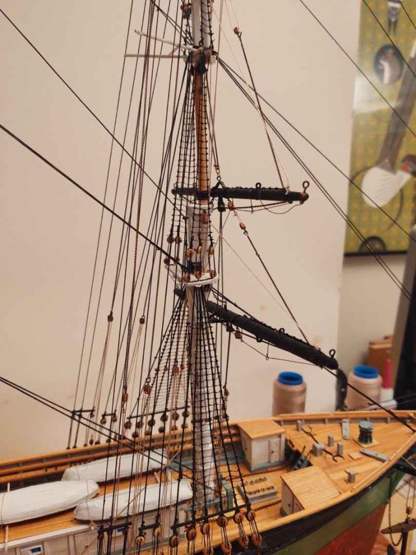
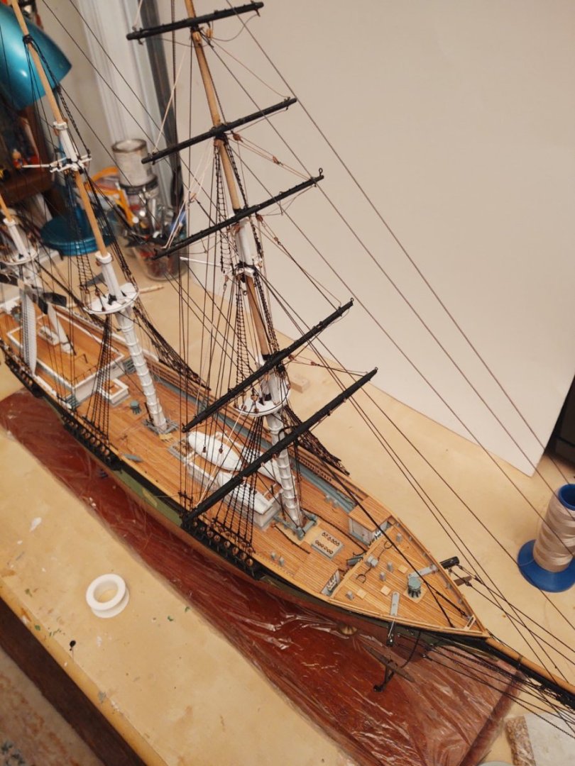
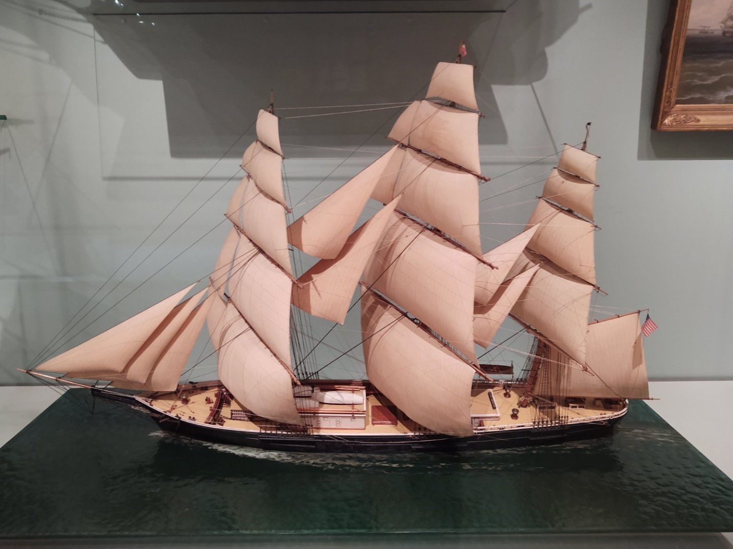
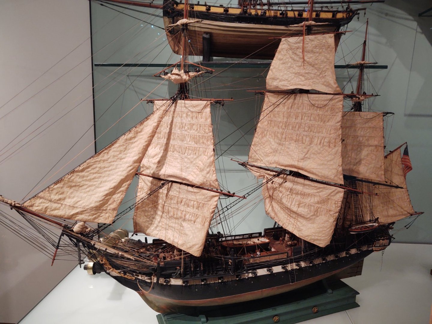
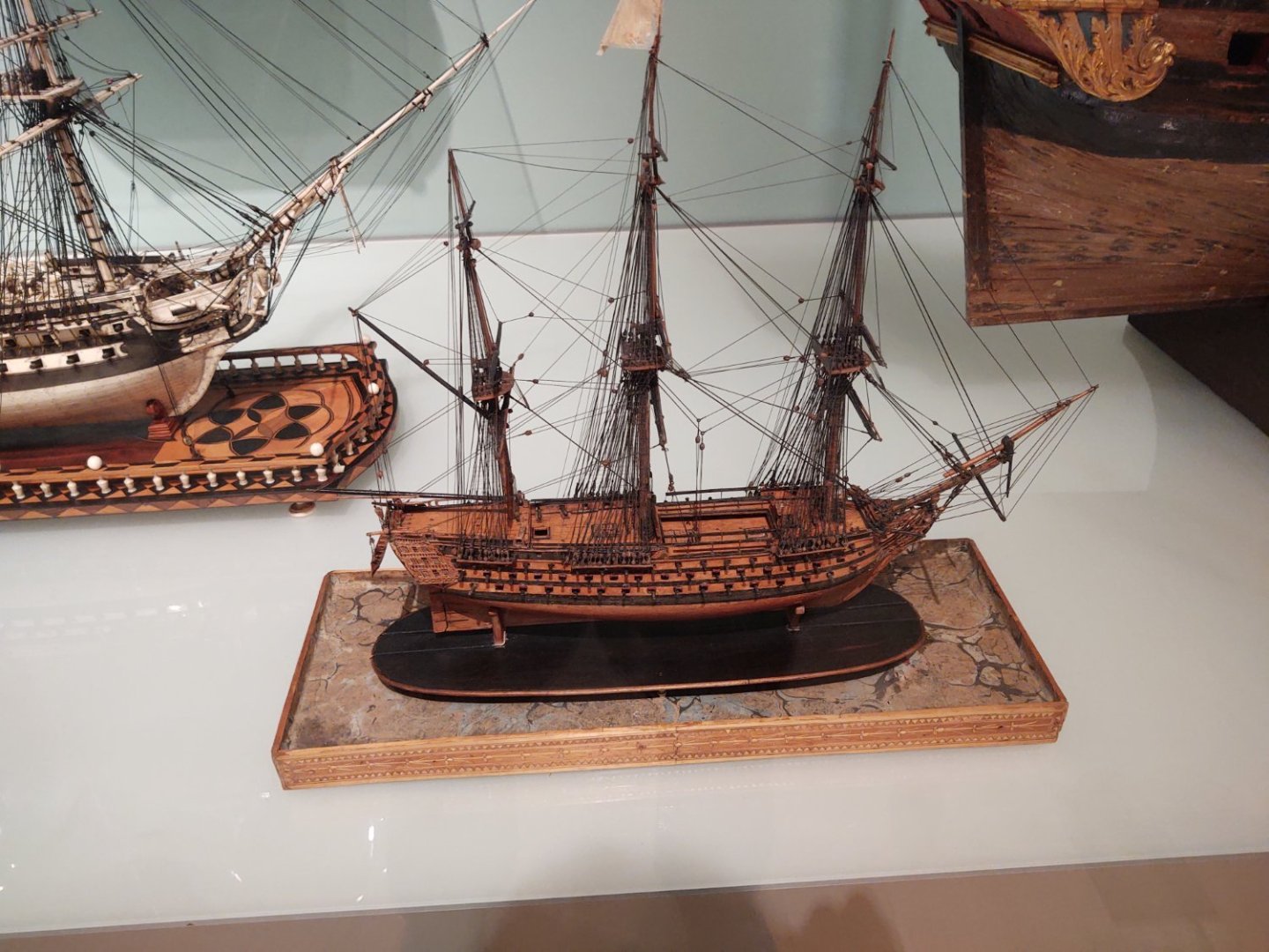
I've made some progress, but not much to show now as we've been in Boston for our younger (and final) child's college graduation (technically she finished her degree in December, but she didn't graduate until yesterday). While we were there we visited the Museum of Fine Arts (she lives about 1/2 mile away) and stumbled into the ship gallery. Thought I might share a couple of clippers from there; have a look at some professional level skills... First up, the Marie Rose at 1:64 And the Flying Cloud at 1:64 Not a Clipper obviously, but a 100 gun ship of the line at 1:64 Tis is Boston, so USS Constitution And he a French ship Héros (1778). This is not technically at any specific scale, but the craftsmanship is amazing considering it's bout 14 inches long. It was made by a French POW around 1781. Regards, George K


- 602 replies
-
- 3
-
-
-
- Flying Fish
- Model Shipways
- (and 2 more)
-
QUICK-FIND INDEXES to BUILD LOGS FOR KITS
gak1965 replied to Dan Vadas's topic in - Index of all kits by brand and subject
Hi, To the person that is maintaining the list. There is a mixup in two of the Flying Fish listings (1851-1900). Rick310's Flying Fish is the Model Shipways clipper JimmyK's Flying Fish is the Corel schooner Thanks, George K -
Thank you. I'm sorry your mom (and family) had to go through that. I'm hard pressed to imagine a worse way to go. Fortunately, as I say, my mother was mostly with it until the very end; but I know far too many that went the other way. Regards, George K
- 602 replies
-
- 1
-
-
- Flying Fish
- Model Shipways
- (and 2 more)
-
Absolutely amazing. It's great to see a model with all that spread canvas. It makes me think about the (usually pretty small) crew having to manage all of that sail so that the ships could make top speeds. The finish line must be visible now... George K
-
Thank you both for the sentiments, it is appreciated. Could be, although the capstans are poorly placed for that. I assumed (as was suggested somewhere earlier) that it was because when you pull down you are limited in how much force you can exert by your weight, vice when you are pushing up from a (basically) immovable object. Turns out the instructions had something to say about that. It appears that the block was only on the topail. Next time, I should RTFM I guess. The instructions are fine, but I've been tending lately to just build from the plans. Regards, George K
-
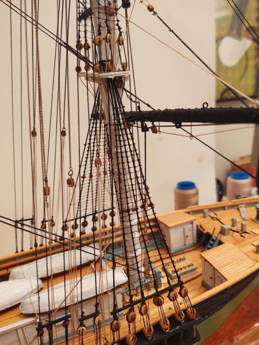
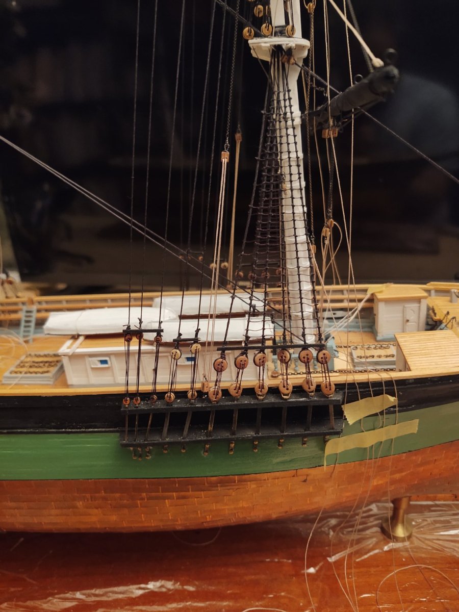
Well, the 'potential' break became an actual one because my mother had gone into the hospital. On that Tuesday evening we were all thinking it was relatively minor, and just waiting for the definitive test that was going to be done the next day, and that Friday morning she was gone. We were grateful to have her as long as we did, and she lived to see both of our children graduate from college, and my siblings' children graduate from high school, and, fortunately, she had her faculties until about the last 36 hours. I think she really wanted to reach her 87th birthday and 64th wedding anniversary, both of which would have been next week, but it was not to be. However, she had her husband, all three children (one of whom was fortunately in town from Denver) and 2 of the three spouses (one had to stay in Denver to deal with one of the grandkids) with her for the last week, hopefully that helped. With that, and the week making various arrangements having passed, I have had some time for a little bit of wood based therapy. Not a lot has changed, but, I mounted the fore topgallant yard, and its halyard. I installed the tackles that hold the topmast halyard, and anchored the first set of live ends from the halyard tackle) on the pinrails. I've installed the first of the fore topgallant sheets and attached it to the tackle on the deck. Once the other sheet is installed, I will anchor everything that terminates on the fife rails (the four chain sheets and the live lifts, as well as the 6 clew lines (which anchor on the pinrails. At that point, I'll add the Royal and Skysail yards, and I'll be close to finished on the foremast square yards. I think I'm going to rig the fore spencer before I have a bunch of main yards in the way. Here are a couple of photos. @rwiederrich or @ClipperFan, the halyard tackle for the topsail yard goes to the pinrail via a deck mounted block (that is, the live end leaves a double at the point where the tackle is shackled to the chain, passes through a deck mounted single and is then belayed to the pinrail). I presume that this is meant to allow the crew to pull up rather than down, which makes sense. The drawings are ambiguous for the other halyards (topgallant, royal, and sky). On other McKay clippers did all the halyards have deck mounted blocks or was that specific to topsail yard because it was so heavy and had that unfortunate lever arm that made it harder to pull into place? As always, thanks for looking in and your encouragement and comments! Regards, George K


- 602 replies
-
- 3
-
-
- Flying Fish
- Model Shipways
- (and 2 more)
-
Looking forward to your build. Just so I understand, you aren't restarting the old Donald McKay model, but rather you are converting an old Glory of the Seas model and using the base from the the prior Donald McKay model (suitably adjusted)? George K
-
Concur. And the main would have been even worse because it was heavier and had a longer lever arm. I think it's no accident that the topsail yards use chains and are attached to two sets of tackles (one each P/S) with greased leather as a lubricant under the parrel band. They must have been a royal pain the posterior to bring into position. Hopefully they didn't need to do a lot of such evolutions most passages. George K