HOLIDAY DONATION DRIVE - SUPPORT MSW - DO YOUR PART TO KEEP THIS GREAT FORUM GOING! (Only 75 donations so far out of 49,000 members - C'mon guys!)
×


gak1965
-
Posts
722 -
Joined
-
Last visited
Content Type
Profiles
Forums
Gallery
Events
Everything posted by gak1965
-
 So, if I understand you correctly, the stay doesn't go through the lubber's holes but rather over the forward edge of the top? I can see that there is not much in the way of clearance between the fore course and the forestay, and that it has a less acute angle than the main or mizzen stays given the anchor point on the knightheads. I figured it would probably limit how far you could realistically move the yard. Was there some kind of reinforcing at the edge of the top or some kind of spreader to ensure that the stay landed on the top directly over the trestletrees? Right now, this is still potentially changeable (as I say, it's not glued in place yet), and my recollection is that the forestay is the highest and outermost of the lines so replacing it won't (shouldn't?) mess up the shrouds, but I need to think about this a bit. Thanks, George K
 -
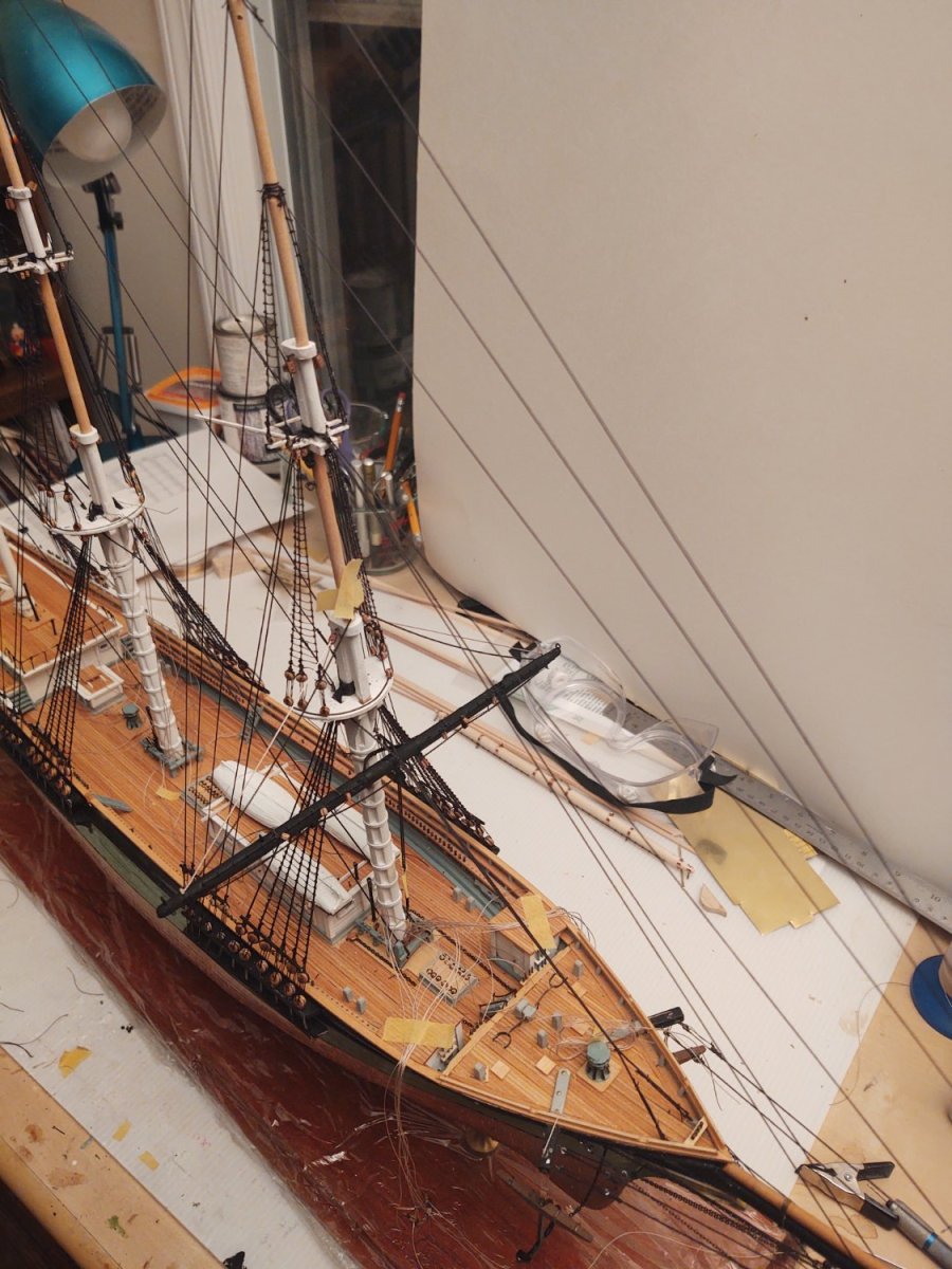
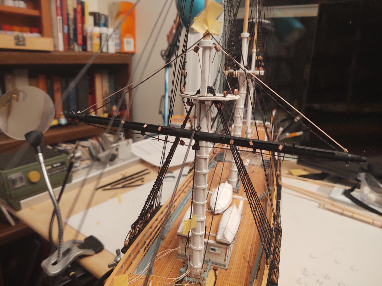
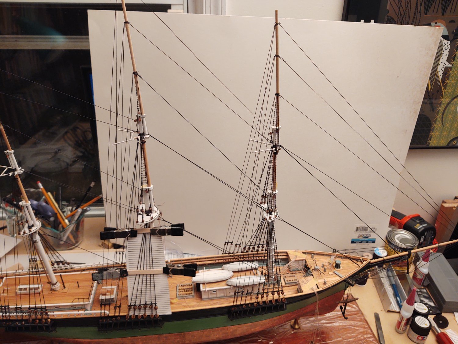
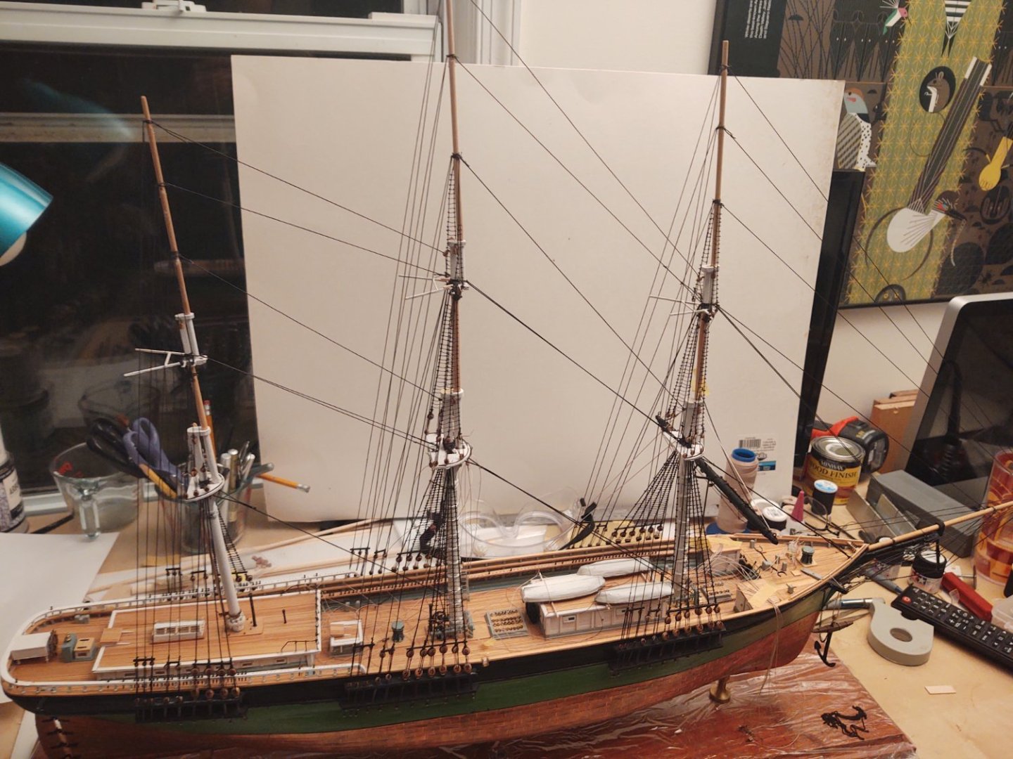
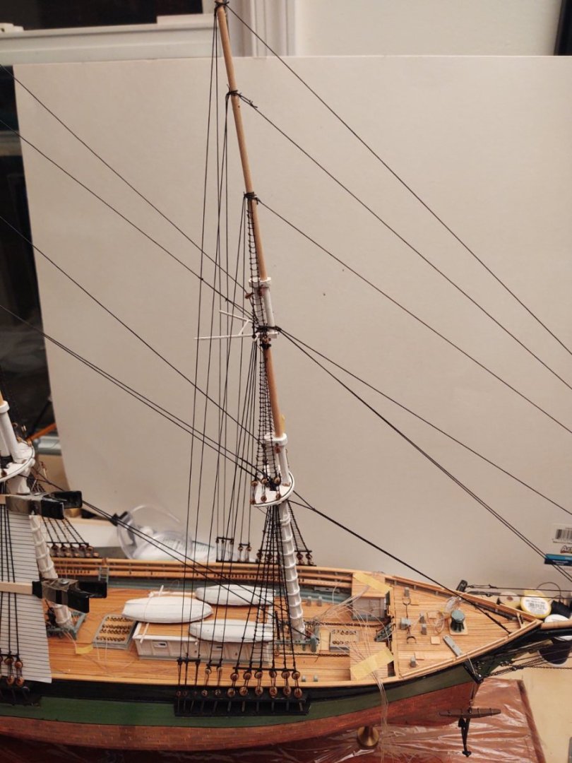
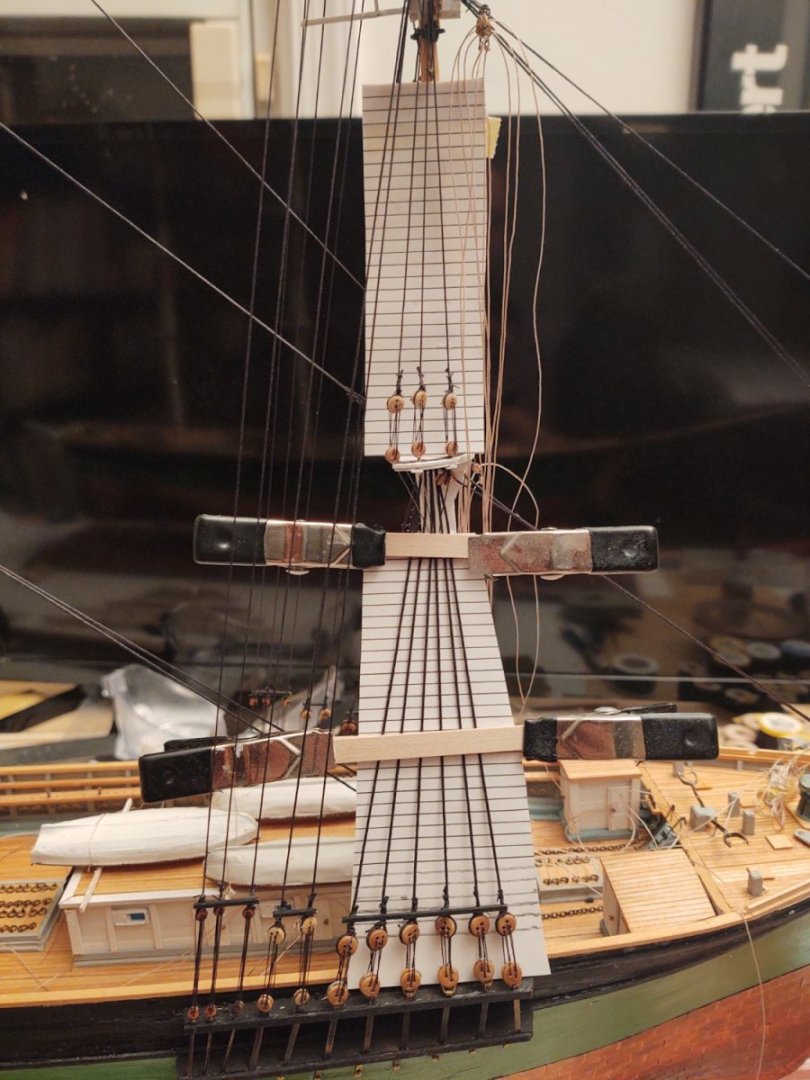
Well, ratlines are continuing apace. Starboard side is now most of the way up the main mast (just a little work on the topgallant to go), and I'll be starting on the mizzen, so the finish line is in sight. However, the real step is the first of the yards is basically ready to go. The photos below show it in position, but it's not glued and I still have to set the chain sling up. The upper end of the chains that are the course sheets are taped to the the mast so I can estimate how long to make them as there is no clew up there to attach the end to. The live end is held with yellow tape you can see in the photo. The next step is to fabricate a hook somewhere above where the tape is and then hook that to the tackles that you can sort of see around the base of the mast. At the moment the running lifts are just taped to the side of the hull, I want to move some of the sheet tackles out of the way (i.e. attach them to the sheet chains before I try to run them down into the mass of line down there. You can (may?) see the blocks for the clew and the reef tackle. On my Niagara I hooked the reef tackle to the clew on the course (above the course the clew was always attached to the sheet). I also mounted the bunt and leech blocks; I'm going to tie a knot in the end of each and leave them sitting up on the blocks. It gives the yard a bit of interest. Another view, with all of the lines strewn around the deck - as I imagine it was as she was being initially rigged. And a quick overview of the whole ship: As always, thanks for looking in! Regards, George K.


- 602 replies
-
- 5
-

-

-
- Flying Fish
- Model Shipways
- (and 2 more)
-
It certainly won’t hurt to put in some pins (although it seems like you would have to sink them into relatively thin bulwarks). As is, though, you would have two glue joints per deadeye (one in the channel and one at the base (bulwark or waterway). CA there should do the job fine. The shrouds shouldn’t have that much tension on them; you want them tight enough to not distort too badly when you tie the ratlines and any blocks, but not so much that they put the masts and tops under undue stress. I have anchored forestays into eyebolt held in place with just a bit of CA and it worked great. looking great so far! George K
-
+1. They have sent me replacement parts (brass strip in my case). I told them that the error might well have been on my part, but they sent it with no shipping charges. I mean I probably make up for it in costs for extra thread and jackstay eyebolts, but still, it's confidence inspiring that they stand behind their product enough to sink the non-zero cost (Connie is $535 as of today) of one of their kits. George K
-
The Revell instructions (and the Heller Passat) suggest putting the yards in place before the standing rigging. I don't know if it's because not everyone rigs their models (strange but probably true), or because much of the standing rigging (at least the shrouds, ratlines, and the deadeyes for the shrouds and backstays) are premade, or some combination of these and other reasons. Every wooden ship model instructions I've ever seen starts with the standing rigging. Probably a good choice with v2.0
- 248 replies
-
- 1
-
-
- Cutty Sark
- Revell
- (and 2 more)
-
I mostly use Tamiya acrylic paints now. They brush well and have a good range of colors. I've needed some odd colors, when Tamiya doesn't have it (or our store is out) I'll use Model Master acrylics (which is made by Testors). The metal colored ones are (so far as I know) pretty much all enamel. I don't have an issue with using enamel on things like copper plate, since (when new) they are shiny anyway. I can't speak to how well anything works in an airbrush, I've only ever brushed
- 248 replies
-
- 1
-
-
- Cutty Sark
- Revell
- (and 2 more)
-
I wouldn't., For two reasons. If you prime the sprues, when you cut off the part you will have a chunk that is unprimed and it could look a little weird after you paint it (I'm thinking of a sort of hole where the sprue was and you have an extra layer of paint). My observation with Revell plastic is that it takes paint well, and you generally aren't in the situation (as I've seen with Heller) where the final color is say black, and it's molded in white, or vice versa. This drove me nuts with the Passat. YMMV, but with the Revell Constitution and Testors paints, no priming was necessary. I bushed everything (including the copper) and there was no problem. Also, FWIW, I've seen people use paint pens to get at fine details on unprimed Revell plastic with no fuss. Something to think about. Good luck! George K PS: Do log the next build! Your first one was coming along great and it can be so helpful to be able to ask questions. I wouldn't be near as far along without the helpful comments.
- 248 replies
-
- 1
-
-
- Cutty Sark
- Revell
- (and 2 more)
-
Oh wow. Did not see that. It works, the lines look phenomenal.
-
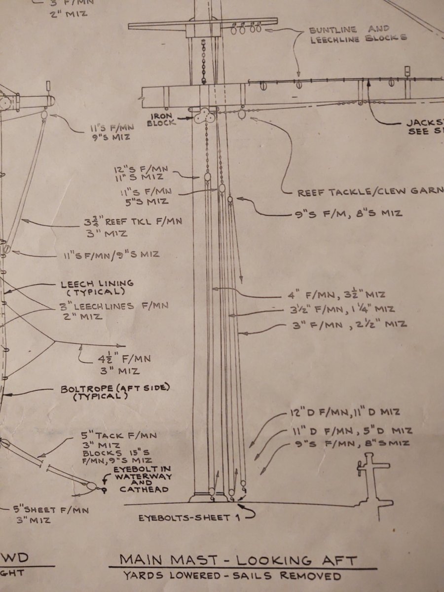
That makes sense. My concern is that I don't see how you would belay this particular line. I goofed earlier, in that it appears that the top and the topgallant both belay on the fife rails (the top is belayed to the fife rail bitt itself rather than a pin). But for the course my read is that the line would have follow the path I've drawn in to the picture below, starting at the base of the mast and going to the marked pin on the bulwarks. Among other problems, the path to that pin has the fore deckhouse in the way. It seems there are three options, all of which involve ignoring the diagrams: belay this at the fife rail somehow, use a spare pin on the bulwarks that at least isn't blocked by the deckhouse, or maybe swap the topgallant for the course sheet. I like the latter best, as it will have the two sheets where the live ends last exit a block on the deck go to the fife rails, and the sheet where the last block is near the top goes to the pins in the bulwarks. The latter looks much more like a bunt or a leach and a lot less difficult to manage on a real ship. Regards, George K
-
One thought. You might want to keep the model around as a practice version (a test bed as Rob calls it) that you can use to try things out and make mistakes. You might therefore consider building up one mast all the way up so that you'll have a baseline going into the new build. Something to think about. Good luck whatever you decide. George K
-
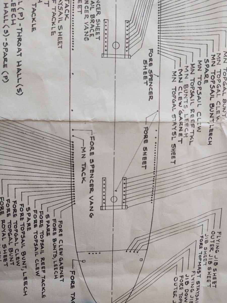
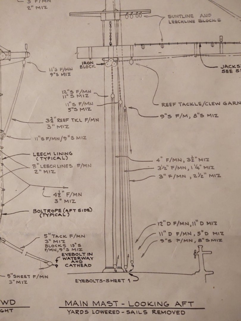
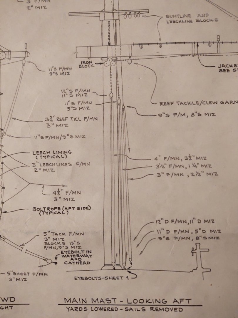
Mike, When you rigged the tackles for the course, top, and topgallant sheets, how did you run the live ends to the pinrails? On the plan excerpt below, the live ends for the course and top sheets leave a double block on the deck by the mast and the rigging plans say that they are belayed on the pinrails. That seems odd to me,was hoping you might have some insight into how you rigged it. Any help appreciated. Thanks, George K
-
Not what you want to hear, but I basically took brass wire, soldered them into closed loops and then replicated what you showed in the picture with the premade loops. Similar for the next segment down, but in that case brass wire to a link, soldered closed. The backing links were made from brass strip that I drilled holes into. Now that I have a drill press that would have been relatively simple; it's harder with a hand drill, I can assure you. I put Tamiya tape on the brass to help prevent the bit from slipping before it bit into the metal. It was a collosal pain in the posterior. George K
-
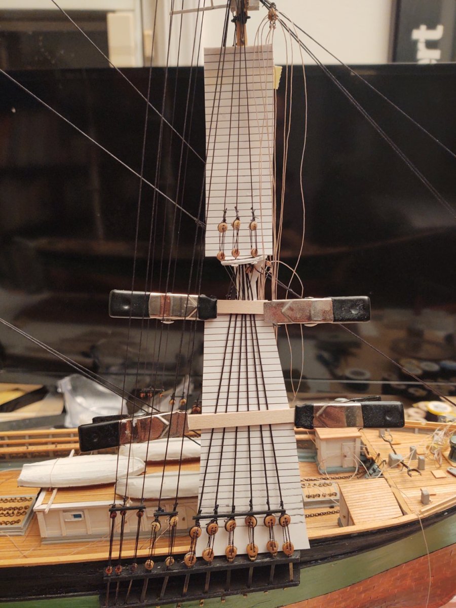
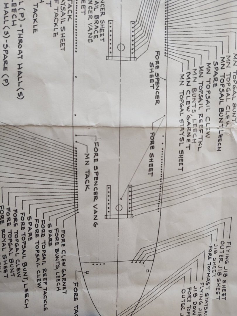
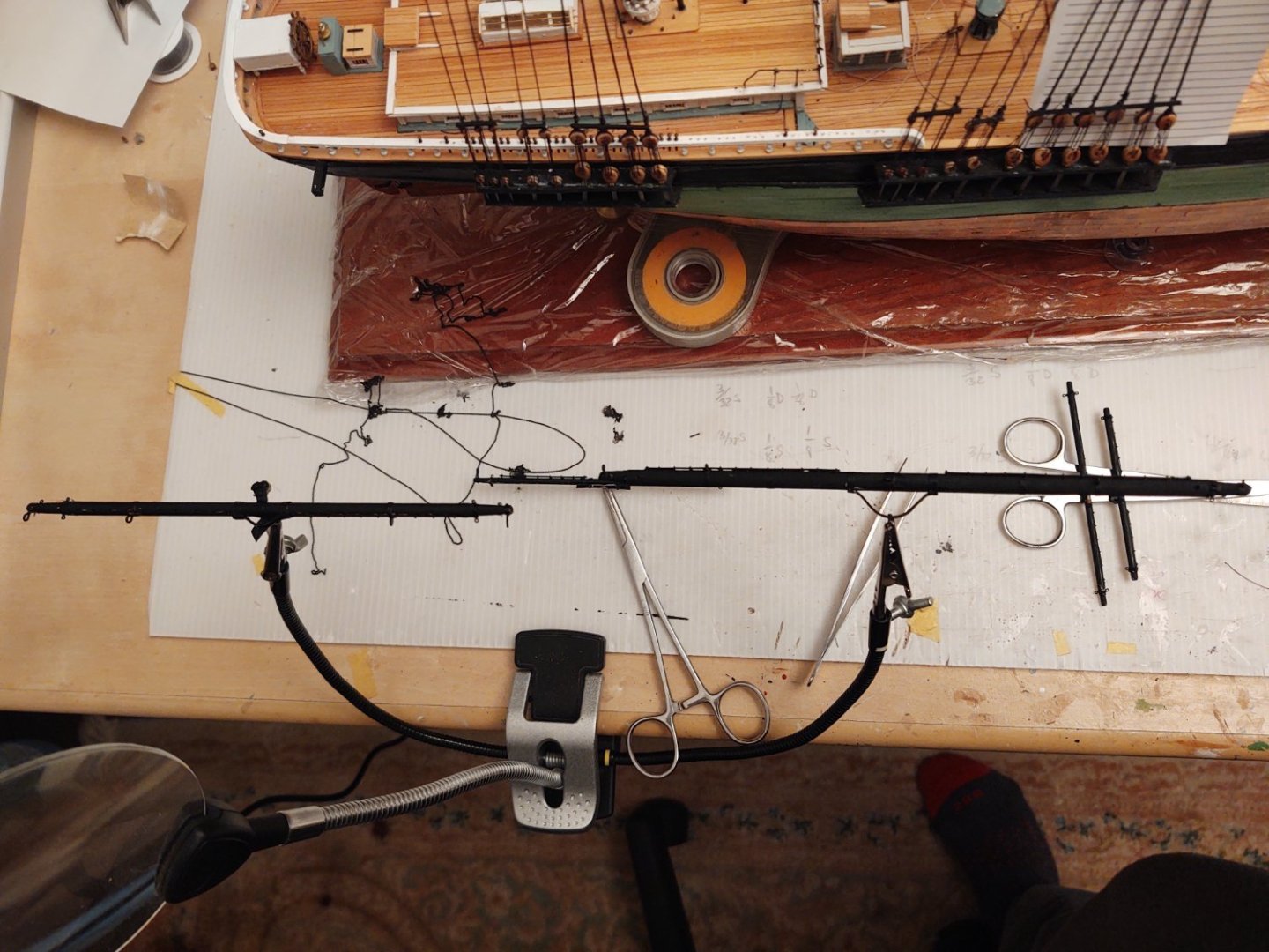
Hello all. My last entry was on the order of 3 weeks ago, not because of massive progress, but rather because of a bunch of other things prevented work. They ranged from the Cherry Blossom 10 mile running race here in DC to visiting my (eek) now 25 year old daughter in Boise where we (double eek) met her boyfriend's parents. I don't quite know why this has me so freaked out (this isn't the first set of parents we've met) but it feels radically more likely to be permanent. Anyway, since returning I have managed to get some time in the shipyard and some progress is being made. First the ratlines on the foremast are done, and I'm starting on the main. I also attached the sheet blocks and painted the masts. Next step is to touch them up and attach the foot ropes. They are all in the photo below but kinda distributed while they dry. Once the ratlines on the main are done, I'm going to start mounting the fore yards. My assessment is that I don't want my elbows to whack one of the yards trying to tie the ratline knots, so, nothing until I'm working on the mizzen. Once I'm on the mizzen it will be time to start making the remaining 4 main yards (the course was finished in the first batch). I am curious about some that that is going to come up soon. If you look at the section of the plans that are shown below, you will see the tackle that attaches the course, top, and topgallant sheet chains to the deck. The other end of the sheets are generally attached to the clew for the yard above (i.e. the other end of the course sheet is connected to the top clew line) when the sails are off the ship. According to the rigging plan, the live ends of the tackle are belayed to pins on the port or starboard pinrails. That (sorta) makes sense for the topgallant (the outer of the three) where the live end is coming down to the deck from a single block where it is attached to the chains. But the other two make no sense to me at all. The live end exits a double block on the deck and then appears to go straight to the pinrail for belaying. Am I missing something here? This seems like it would leave a set of two lines at each mast, port and starboard that runs from the deck to about 4 feet off the ground. What a colossal pain in the posterior that would be. And I keep hearing the bosun's mates telling me to watch lines on the deck. I know that it isn't impossible, the lines that control the tiller on the Niagara are equally in the way, but geez, these ships carried passengers as well, and I dunno there has to be a better way. I looked for signs of deck blocks near the pins that would at least keep the lines near the deck (easier to step over) but the plans show blocks for other lines, but not these. So, am I mad? Missing something? Or is this just the way these ships were rigged? Any help appreciated. As always, thanks for looking in and the likes, George K.

- 602 replies
-
- 6
-
-
- Flying Fish
- Model Shipways
- (and 2 more)
-
I use thick CA on all the knots. Use a fine applicator (fresh bottles of Bob Smith glue have really fine ones). Try not to glop it on, you just want to stabilize them. The thicker stuff takes longer to cure, more time to fix things in my view. Std. disclaimer, George K
-
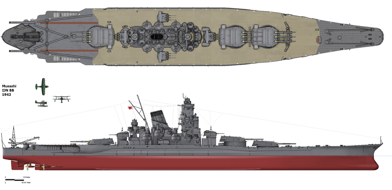
Both the Yamato and the Musashi had their secondary armament changed during the war, removing two of the 6 inch turrets to make room for more anti-aircraft batteries. This drawing (from Wikipedia) https://en.m.wikipedia.org/wiki/Yamato-class_battleship#/media/File%3AMusashi1942.png, license is CC-BY-SA) shows what the Musashi looked like in the early war configuration. Does the Trumpeter kit support both the early and late war variants?
-
I haven't seen the plans for the masthead of the CS, but on the other ships I've done, the shrouds have tended to be in pairs either port or starboard which tend to be the most straightforward. With 5 shrouds that still would leave you with one singleton. I have typically seized the singleton at the masthead before I attached the deadeye. That way I could give the shroud a nice tail while seizing, and then tighten followed by gluing the seizing thread at the masthead. Once that was dry, I could mount the deadeye at the correct distance and seize that in place. FWIW, I put glue on the circumference of the deadeye, and once that was stable, I could seize the lines together. Also, unless CS has something different, I add the sheer pole after I had tensioned and secured the lanyards. I also tended to cheat a bit, I'd use a bit of adhesive on the deadeye "eyes" to stabilize the lanyards before they were anchored. Regards, GAK
- 248 replies
-
- 2
-
-

-
- Cutty Sark
- Revell
- (and 2 more)
-
Some came with the kit, although in line with all three model shipways kits I've done/doing, nowhere near enough. I buy them from Model Expo. It's about $14 for 500 of them. https://modelexpo-online.com/75-x-6mm-Brass-Jackstay-Eyebolts-500-pcs_p_781.html. On a separate note, one thing I realized is that for the lower shrouds, doing the starboard side means starting on the second shroud (L to R) except for every 6th ratline, not the first. I almost started tying on the leftmost shroud (as I face the ship), which would have been interesting to try to repair.
- 602 replies
-
- 1
-
-
- Flying Fish
- Model Shipways
- (and 2 more)
-
Thanks for looking, in and for the encouragement. Another brief update. First, the full set of fore yards are done, save for painting, footropes, and blocks, as well as the main course yard. Looking at the photo, I see that the main course yard is upside down compared to everything else. Oh well. Even if I wanted to make more yards now, I doubt I have enough eyebolts left, so, an order needs to be made. Which means, of course, that it's back to tying ratlines. Or as that old corporate adage goes, the ratlines will continue until morale improves. The good news is that it feels like I'll soon be exiting this long phase during which lots of stuff is being done, but the ship isn't changing its appearance much. It's been two months since I started tying ratlines (and making yards and gin blocks, and cranes) and probably another 3-5 more weeks on the starboard ratlines (during which I'll paint the fore yards and mount the footropes). But once that is done, the ship should start changing appearance at a reasonable pace which will be a relief. As always, thanks for looking in! Regards, George K
- 602 replies
-
- 4
-
-
- Flying Fish
- Model Shipways
- (and 2 more)
-
BlueJacket makes photoetch safety nets for the USS Arleigh Burke, which I think is the same scale. I thought that @MrBlueJacket mentioned elsewhere that it is possible to get parts that are in their kits (but not something that they routinely sell separately) by calling their office. You might check this.
- 19 replies
-
- 2
-
-
- Putnam
- BlueJacket Shipcrafters
- (and 3 more)
-
I'm with Ian here. Print a sheet with lines spaced 14-16 scale inches apart, cut out, attach to shrouds to give you a pattern. I lack the skill and patience to do clove hitches, I just use simple overhand knots that I secure in place with a little CA glue. I find I can do 5-6 rows, and then carefully position and secure with the glue. I'll then move to another set of shrouds while the first batch sets, and then I can nip off the excess on either end. That shroud jig is an abomination. I tried it on my Passat and it was a complete disaster, nothing stuck properly, I gave up and made them the way Ian describes (and that I've done on all of my subsequent ships). As Ian notes, there are a lot of simple jigs people make to do the spacing. This is a common method; it's from my Niagara kit and I've used this method on three ships now. Also as Ian notes, methods like this keep the lanyard spacing the same, they don't keep the upper deadeyes in a line. It may not be a problem, but if you notice a bend in the line of the upper deadeyes and it bothers you, you may want to space it with this, and then adjust ever so slightly to maintain the line better. Regards, George K

- 248 replies
-
- 2
-
-
-
- Cutty Sark
- Revell
- (and 2 more)
-
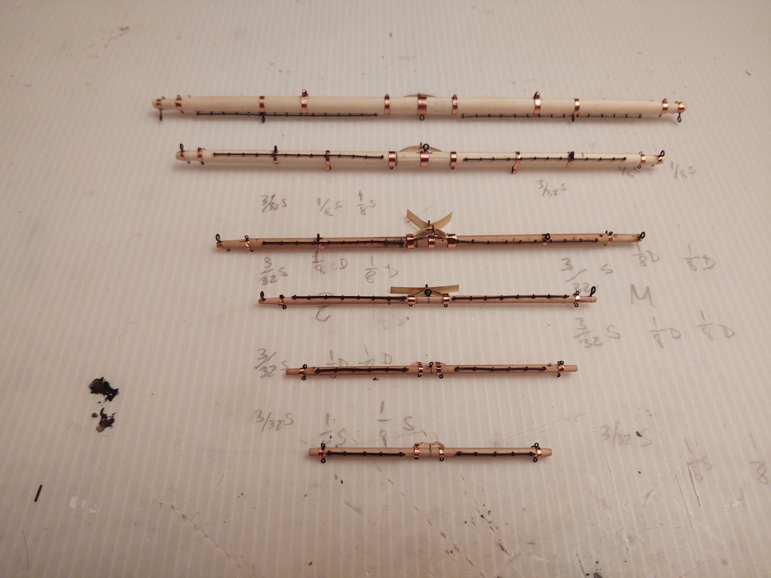
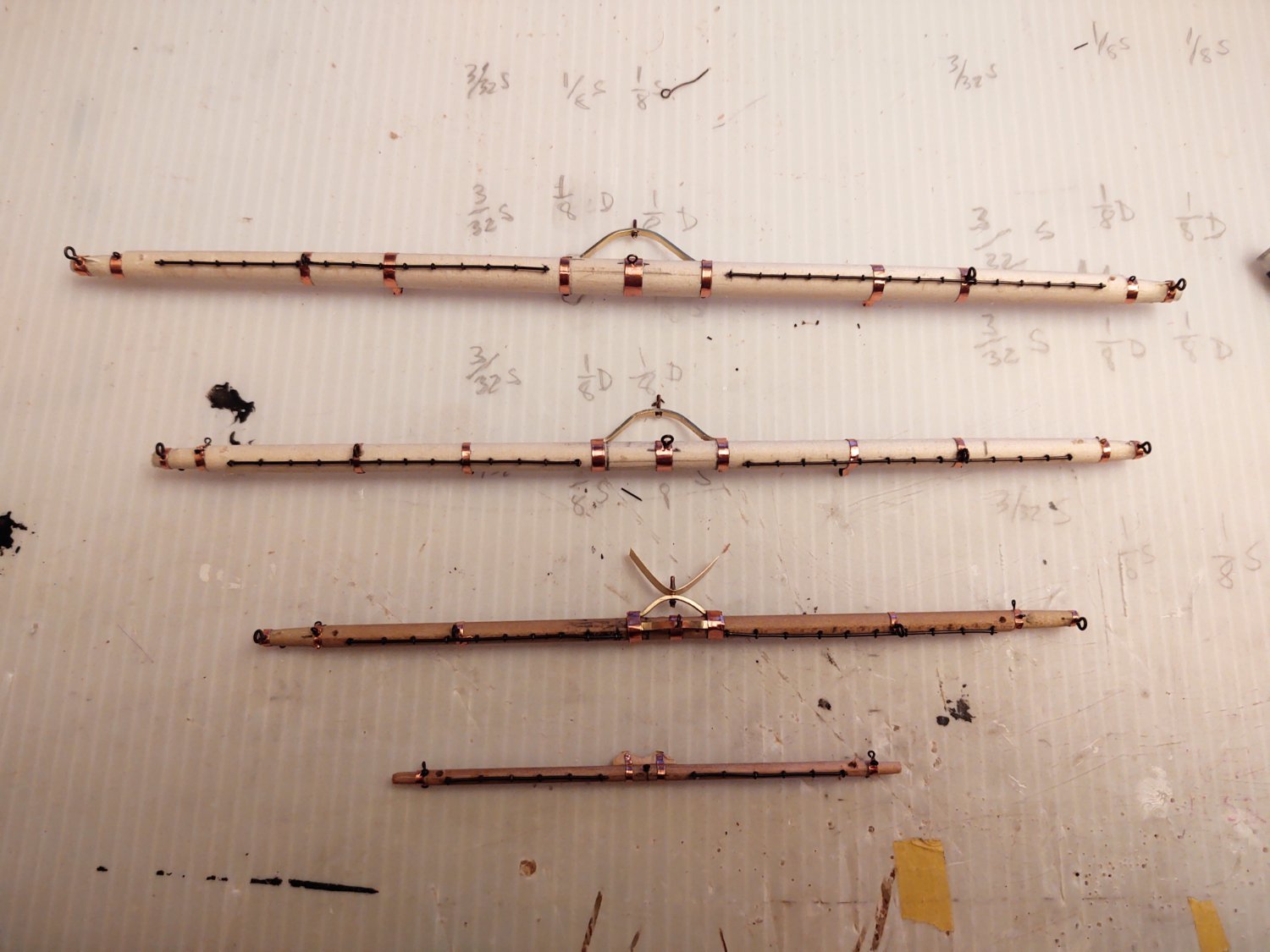
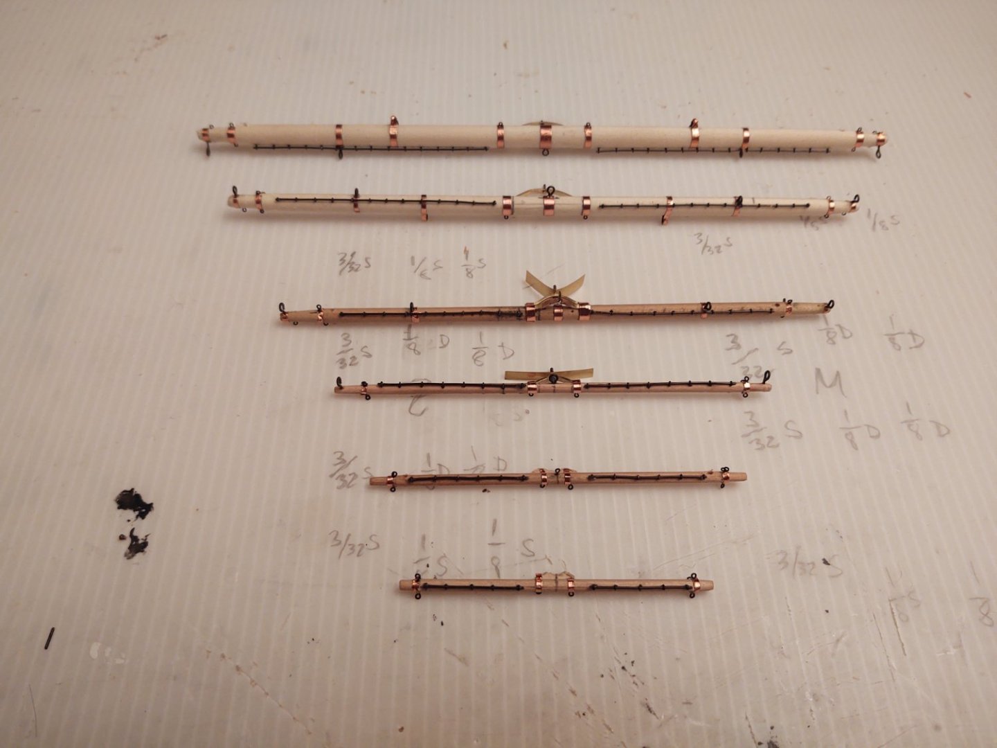
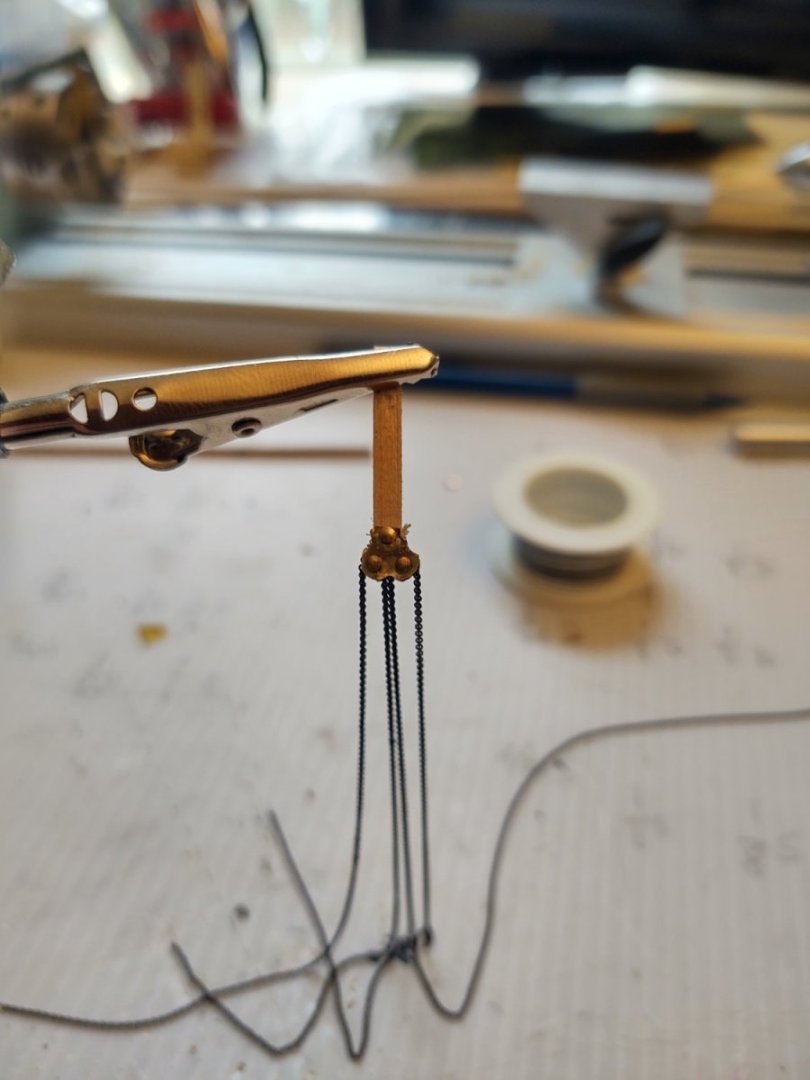
Well a brief update. Work continues apace on the yards. I had already made the main course, and I decided I would make all 5 yards for the foremast before I restart knot tying. Probably a mistake b/c no doubt I will lose some of my facility with the knots picked up over the previous several weeks, but well, damn the torpedoes and all that. So, here are the first 4, top to bottom main course yard, fore course yard, fore top yard, fore royal yard. The fore topgallant yard is missing because I wound up binning two of them, one after my drill bit basically chunked out the underside, and a second after it snapped while I was sanding the yardarm. The metal piece attached to the truss is going to wrap around the mast and then be trimmed to size to represent the iron work. It's 0.002 in thick brass that I cut from a sheet. One thing I have learned is for the small diameter yards is to only sand the yardarms out on the live end of lathe. Once that end is made, I reverse the yard and once again sand at the live end. Hopefully I won't bin any more due to stress failure of the narrow dowels. The one thing not yet on the yards are the sheet blocks (present on the course and top yards) which were iron and hang from under the yard. I tried a bunch of things that did not work to make the blocks, but I think I have something that works now. Here is a photo of the first one. The block is hanging from the wood strip which I am going to trim down to just above the single nail on the top and CA glue to the yard. I made the frames from two square pieces of 0.002 inch brass sheet, which I sat on top of each other, held together with some Tamiya tape. I then drilled the three holes, 2 on the bottom, and one on the top. I ran small brass nails through the holes in one sheet. On the two bottom nails I slid some tiny parrel bead to space the top and bottom frames, and on the top, I put a small wood strip with a hole drilled into it and the used my dremel to create a rounded end so that there would be some space. Next, I put the other piece of brass sheet with holes on, sending the nails through the holes and used CA glue on the outside to hold everything in place. trimmed the nails, used my dremel to shape the brass so that it has the shape above (basically 3 intersecting circles). When I mount them, I'm going to keep chain in place, they were far to much of a pain to try to thread them on the mast, on the ship. That probably means some wasted chain, but I'd rather buy more chain than become completely frustrated by my inability to get it in place. Anyways, thanks for looking in! Regards, George K.

- 602 replies
-
- 6
-
-
- Flying Fish
- Model Shipways
- (and 2 more)
-
I'm sure it will be great. Anyway, rigs changed over the life of a ship (often just when a new captain came on board), the specific pin to anchor a line that is shown on plans is just someone's guess as to what made sense - probably changed for some lines throughout the voyage. The point is to build something you are happy with and continue to improve, and she's looking great. Just swapping out those plastic deadeye lanyards will make a huge difference. Good luck, George K.
- 248 replies
-
- 1
-
-
- Cutty Sark
- Revell
- (and 2 more)
-
I would start aft and work forward. Going the other way is the mistake I made on the Flying Fish. The issue is that if you have forestays that mount onto the mast further forward the attachment points become harder to reach once you have shrouds and backstays on the more forward mast. Agree on bottom to top, although I found that the most effective thing was to reeve everything, and then tighten at the end. In some cases (I.e. if the royal/sky sail spar needed aligning) I would start tightening at the top, but generally I followed the bottom up approach. George K
- 248 replies
-
- 2
-
-
- Cutty Sark
- Revell
- (and 2 more)