


markjay
-
Posts
410 -
Joined
-
Last visited
Reputation Activity
-

 markjay got a reaction from shipman in La Créole 1827 by archjofo - Scale 1/48 - French corvette
Just found this awesome build, words escape me. Recover soon.
-
 markjay reacted to Jaager in Sanding Sealer - when/how to use it
These terms are often used in a fast and loose manner with no anchor to what they really mean, so some posts can be confusing.
I think these are functionally precise definitions:
A sanding sealer, or sand-n-sealer - a clear and thick mixture with micro particles - the main use is as a base coat on furniture built using open pore wood species such as Oak, Walnut, Ash... It fills the open pores so that when viewed at an oblique angle, the final surface appears to be glass smooth.
Opinion: it is too thick for scale use. Open pore wood is best not used at all on scale models if the wood is to be clear finished. There are other ways to fill pores before painting.
A primer is generally a 50% diluted clear material intended to soak in deeply and limit any additional material layers to being surface only. The traditional primer is half strength shellac. It is easy to apply, easy to undo, quick to dry, low cost, and compatible with most any other materials applied over it.
If an clear oil finish is the goal, half strength Tung oil can be its primer coat or I am guessing half strength Linseed oil will serve as as its primer. Both would want additional time to polymerize before being covered over. 50% shellac is probably more cost effective as a primer for these.
Shellac is alcohol based and the oils are organic solvent based. They do not raise wood grain.
Paint can be its own primer, it just requires more coats to get a dense enough surface layer. If the paint is water based, the surface may need fine sanding to remove any raised grain.
A dye is a monomolecular solution of a pigment that soaks into wood and changes its color. It does not change the surface. It does not obscure wood grain. If anything, it increases the contrast, This is not necessarily a wonderful thing on a scale model, so having grain with lower contrast is a deciding factor for the choice of wood species if it is to be clear finished.
Dyes come water based and alcohol based. The water based dye soaks in more deeply, but the first application raises wood grain unless a dilute PVA/water solution is used first and then sanded when dry. The alcohol based dye does not raise grain and on a model, any effect that a deeper water dye penetration may provide is probably too slight to be noticed, so alcohol based is probably the better choice. No primer effect with either is there.
A stain is a suspension of pigment particles in a solution with a polymerizing binder. This is also the definition of paint. The pigments are wood colored and some commercial products may also contain a dye so that it can advertise that it penetrates.
Opinion: on a model, if it is wood that needs a stain before clear finish it would serve you better to replace this wood species with one that needs no pore filling or grain hiding with a semi-transparent paint - which is what a stain is. The purpose of a stain is to try to make a low quality wood appear to be a high quality wood ona piece of economy furniture.
-
 markjay got a reaction from FriedClams in La Créole 1827 by archjofo - Scale 1/48 - French corvette
Just found this awesome build, words escape me. Recover soon.
-
 markjay got a reaction from archjofo in La Créole 1827 by archjofo - Scale 1/48 - French corvette
Just found this awesome build, words escape me. Recover soon.
-
markjay reacted to BenD in Ropes of Scale developments and updates
I've been working out the formulas for the Gutermann E thread and I have some pictures to show. I purchased the color card and bought every color that I thought would look like rope. I like this thread quite a lot. It's easy to work with, has zero fuzz, low shine, and is very strong. It's also a quarter the cost of cotton thread and I don't have to treat it with book-binders PVA. This should make my synthetic line of rope more affordable.
On the left we have pale beige. In the middle we have tan which is very close to my cotton tan color. On the right we have a golden brown, I think it's close to manila hemp. The tan I'll get into production for sure. The other two however need some testing onboard some models before I go any further.
For the standing rigging colors we have the usual suspects. Black on the left. Very dark brown in the middle. Dark brown on the right, It's actually a little darker than what is in the photo as I turned the brightness up a bit. I like them all to be honest and will probably have them all available on my store.
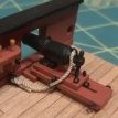
Here is a 2.4mm cable I made with the tan color. Very crisp detail with no fuzz!
I'm going to put the dark brown and tan into production and I hope to have them online by early next month. I'm also going to look into other types of thread for the lighter colors. Amann Serafil I hope has some good options but the color card still need's to arrive.
Thanks for looking in!
-

-

-
-

-
-
-

-
.thumb.jpg.6f665fb783d9c8f33a6312aab6074f93.jpg) markjay got a reaction from Michael Scarborough in Need a seizing tutorial
markjay got a reaction from Michael Scarborough in Need a seizing tutorial
FYI, Jay Brent has several other U tubes that are pretty good in showing and explaining other details about the rigging process. Sort concise and to the point. Highly recommended.
-
 markjay got a reaction from BenD in Need a seizing tutorial
FYI, Jay Brent has several other U tubes that are pretty good in showing and explaining other details about the rigging process. Sort concise and to the point. Highly recommended.
-
markjay got a reaction from mtaylor in Need a seizing tutorial
FYI, Jay Brent has several other U tubes that are pretty good in showing and explaining other details about the rigging process. Sort concise and to the point. Highly recommended.
-
markjay reacted to Ryland Craze in Need a seizing tutorial
The video above was made by Jay Brent who goes by Modeler12 on MSW. He has not been active on the forum for several years. I hope he is OK.
-

-

-

-
-
markjay got a reaction from Michael Scarborough in Need a seizing tutorial
Check out this U tube video.
-

-
-
-