HOLIDAY DONATION DRIVE - SUPPORT MSW - DO YOUR PART TO KEEP THIS GREAT FORUM GOING! (Only 13 donations so far - C'mon guys!)
×


tkay11
-
Posts
1,827 -
Joined
-
Last visited
Content Type
Profiles
Forums
Gallery
Events
Everything posted by tkay11
-

Echo by davec - FINISHED - cross-section
tkay11 replied to davec's topic in - Build logs for subjects built 1751 - 1800
Very nice, Dave. I have had the same experience. After making several parts in what I have thought to be exactly the same way as on a previous model, somehow, magically, they seem to come out better than the earlier ones. Tony -
What a nice model! Thanks for the many ideas you've provided in terms of paintwork and metal work in addition to your usual lovely craftmanship. The flintlock cover is a clever addition. I also like the simplicity of the base. Is it stone? What's next? Tony
-
Wonderful to see your work on this. I also appreciate the shots of a similarly-sized boat to show just how big it is. Thanks! Tony
-
Nicely executed. I'm impressed by the speed at which you have been able to work. Congratulations! Tony
- 104 replies
-
- 1
-

-
- sherbourne
- caldercraft
- (and 1 more)
-
There are some very simple jigs you can make to ensure the deadeyes are all in line (though on real ships they quite often were not that straight, so this is more of a model-making convention). I made mine with paper clips. See the following, a few paragraphs into the post: By the way, I strongly recommend the late Hubert Sicard's site Wooden Ship Modeling for Dummies. This is now maintained by his family. A lot of it is free, but you can get a lifetime subscription for $40. I used it extensively. It has plenty of free videos and focuses on using the most basic equipment with the minimum of power tools. Tony
- 104 replies
-
- 1
-
-
- sherbourne
- caldercraft
- (and 1 more)
-
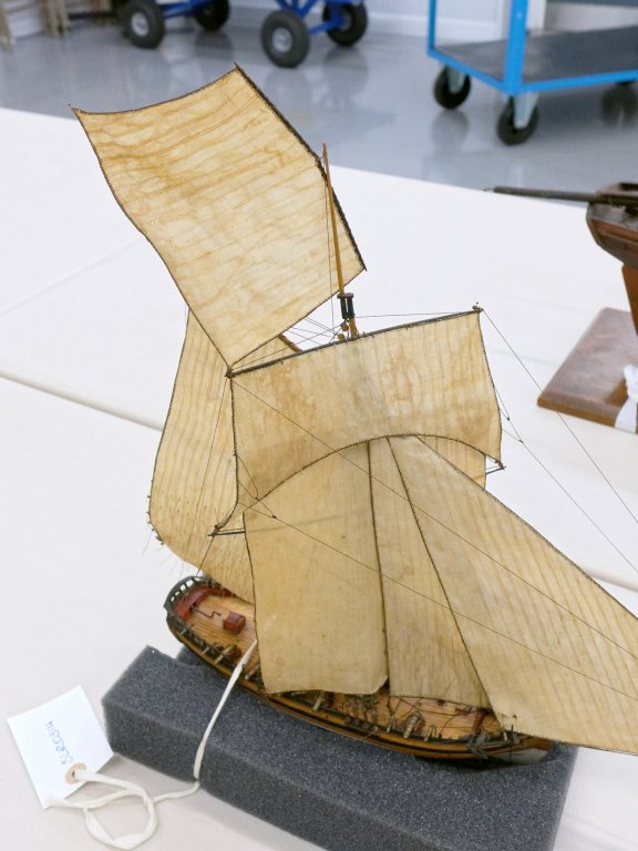
I based my own rigging of the Sherbourne on Petersson's book, and found it very helpful. However, I did augment it with more precise details from Steel, Marquardt and others. The original plans in the NMM came with no rigging plan, so it really is up to you how you rig it, within the various options that these different authors and paintings portray. Not only were there many different approaches to the rigging of a cutter at the time, in terms of number of yards, positioning of the topmast, and belaying plans but every shipyard had its own way of doing things, and captains would often change the rigging to suit their own requirements. Finally, I do recommend that you go with the sail plan, and therefore the rigging plan, that pleases you most -- especially if you plan to show the model with sails. It should be noted that the kit differs from the original plans in some details, notably the windlass, so you also have to decide whether you want to attempt to go for some original recreation (which to my mind is impossible) or whether you see this as a generic reconstruction of what these lovely ships used to be. There's a huge amount of discussion on most of these aspects on this site, either in detailed build logs or in discussions of each of the different details. You are doing a really nice job so far, and whatever you decide, it's going to end up as something deeply satisfying to you and to those around you. Tony
- 104 replies
-
- 3
-
-
- sherbourne
- caldercraft
- (and 1 more)
-
Good neat work. Very pleasurable. Tony
-
It's been a pleasure to watch. Congratulations! Tony
- 84 replies
-
- 1
-
-
- sherbourne
- caldercraft
- (and 2 more)
-
I think every builder has problems with boo-boos. There's an entire topic devoted to just this aspect of a modeller's life. Tony
- 104 replies
-
- 1
-
-
- sherbourne
- caldercraft
- (and 1 more)
-
Very neat work. Tony
-
Nice progress. Normally the hull planks would go over the edge of the transom timbers as they would be nailed from the outside to them. However, if you are going to paint the hull, you should be able to hide the fact that they are lying on the inside of them. Even if you don't, I don't think it would be worth tearing off your planking to re-do it as it is quite neat. You can check this with some of the build logs of the Sherbourne. Tony
- 14 replies
-
- 1
-
-
- sherbourne
- caldercraft
- (and 1 more)
-
@mjh410: The machine I use for milling is a straightforward adaptation of a 50W Proxxon Micromot drill, which I made in 2013 for my earlier builds and is discussed with photos at the beginning of this build log. The only essential adaptations are (1) a clamp for the drill stand made of wood which has an old tuner knob glued to a 6mm bolt to act as a height adjuster, and (2) a dial gauge on its own stand. You can see this in the section on Stem, Stern and Keel on the first page of this build log, and the link to the post is: You'll find my instructions on making the clamp on this site at: Many people have said that these small Proxxon drills are not made for milling as the bearings are not designed for lateral thrust. However I have not had any problems so far as I keep my cuts shallow and I only use it on wood. The advantage of these Proxxon drills is their high speed (up to 20,000 rpm) which is ideal for using small diameter milling bits (1-3mm) in wood. A key problem is ensuring that the drill clamp on the drill stand holds the drill truly vertically. I had to insert a strip of wood between the drill clamp and the stand as the stand I have is the cheapest possible and not build to such good tolerances as the Proxxon MF70 mill (the standby for a vast number of modellers working with model ships). Tony If you want to know more, please do ask.
- 124 replies
-
- 2
-
-
- longboat
- Chaloupe Armee En Guerre
- (and 1 more)
-
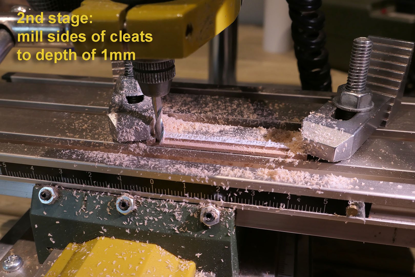
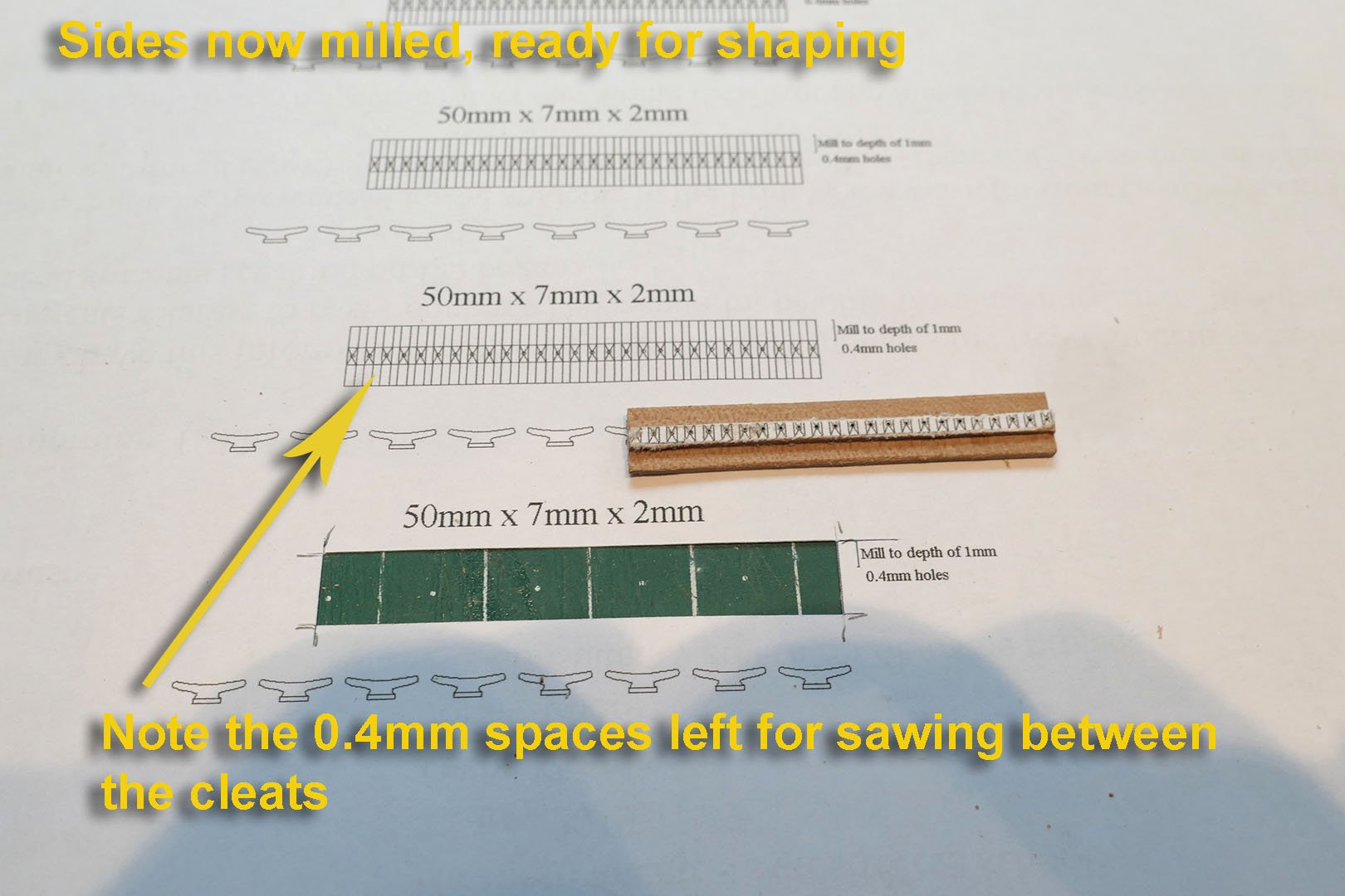
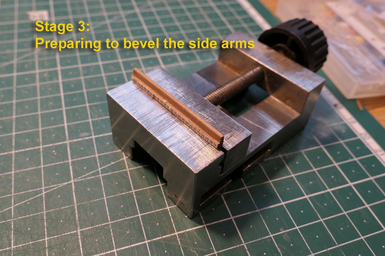
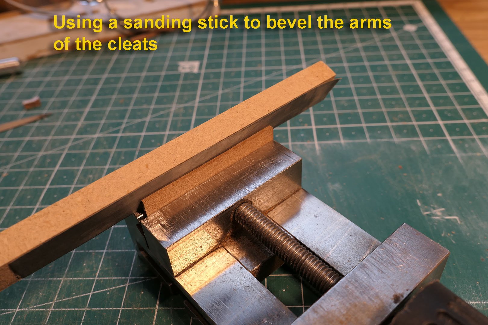
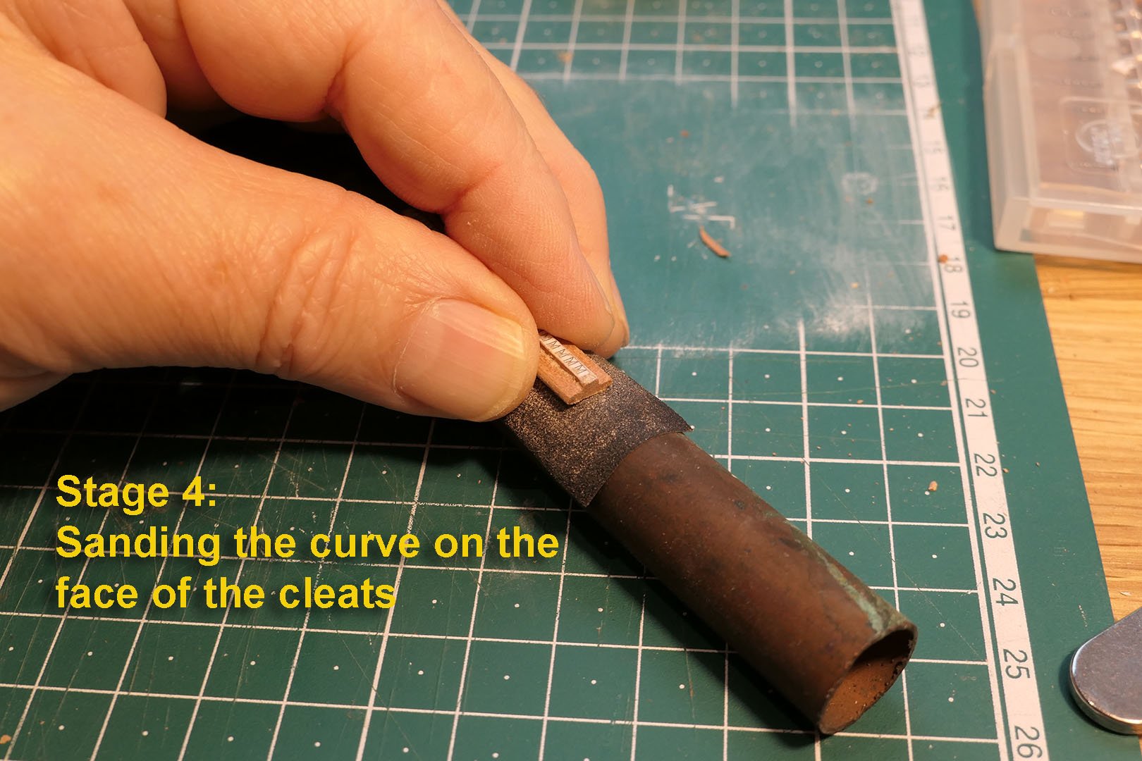
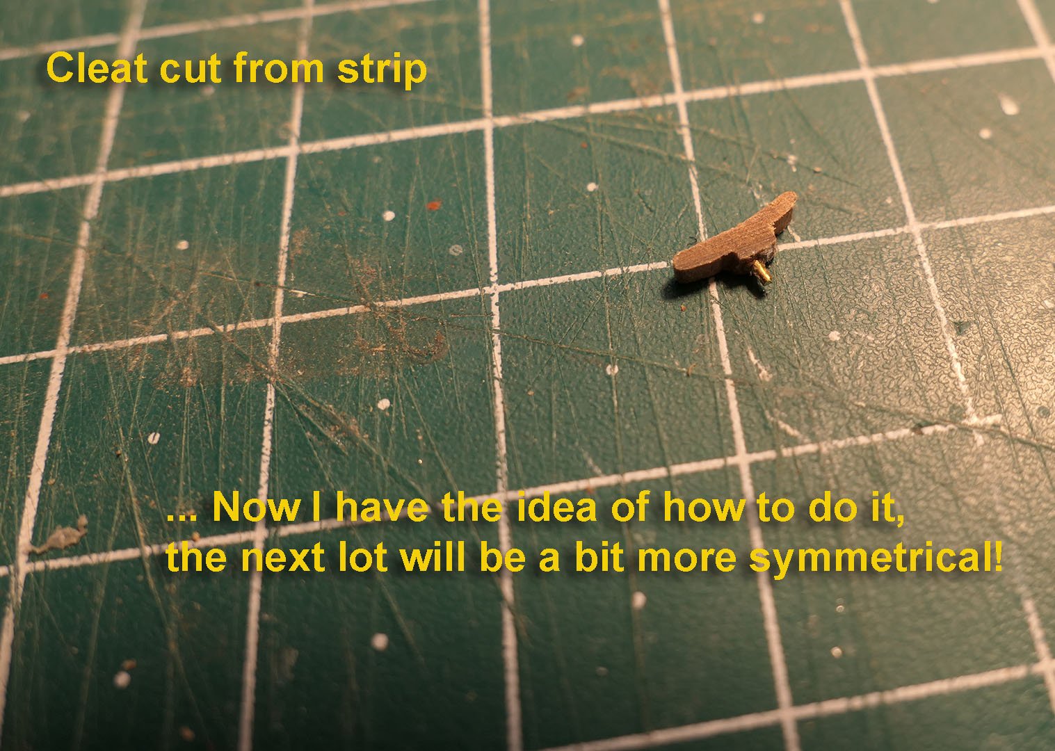
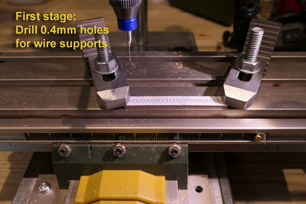
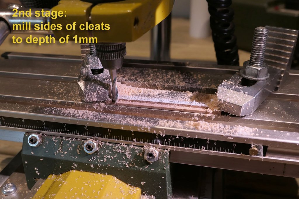
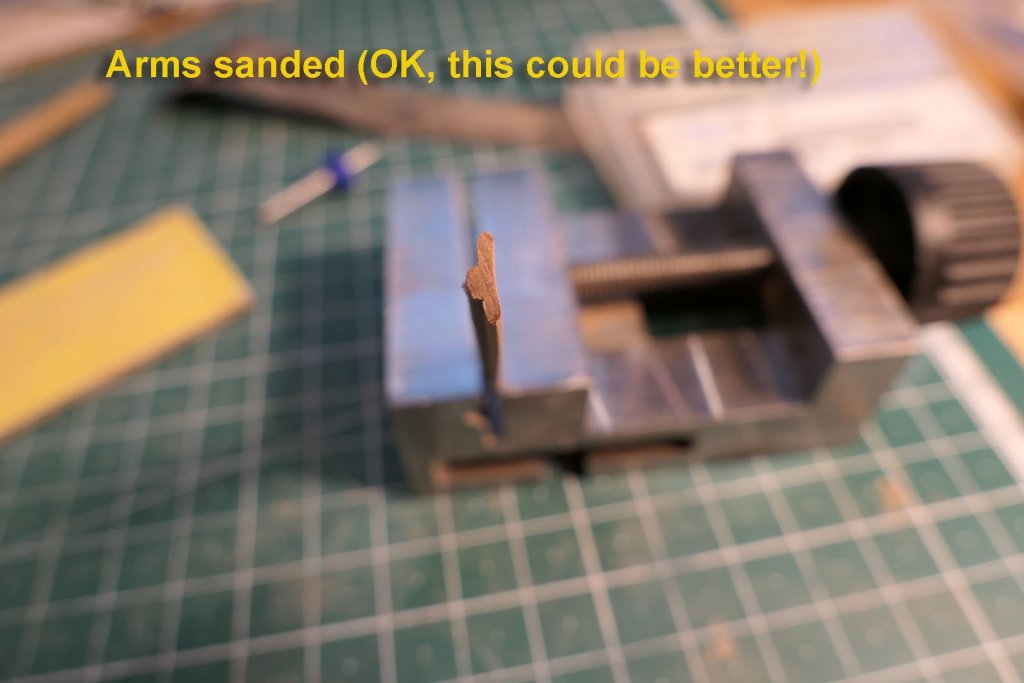
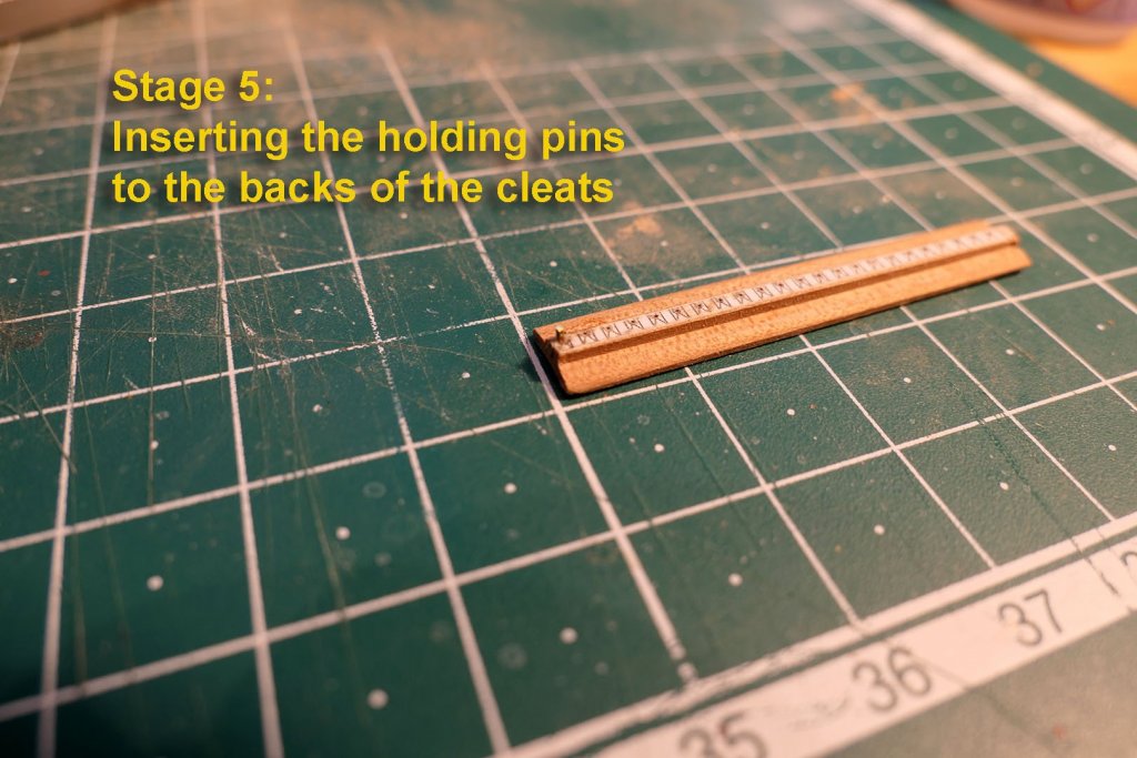
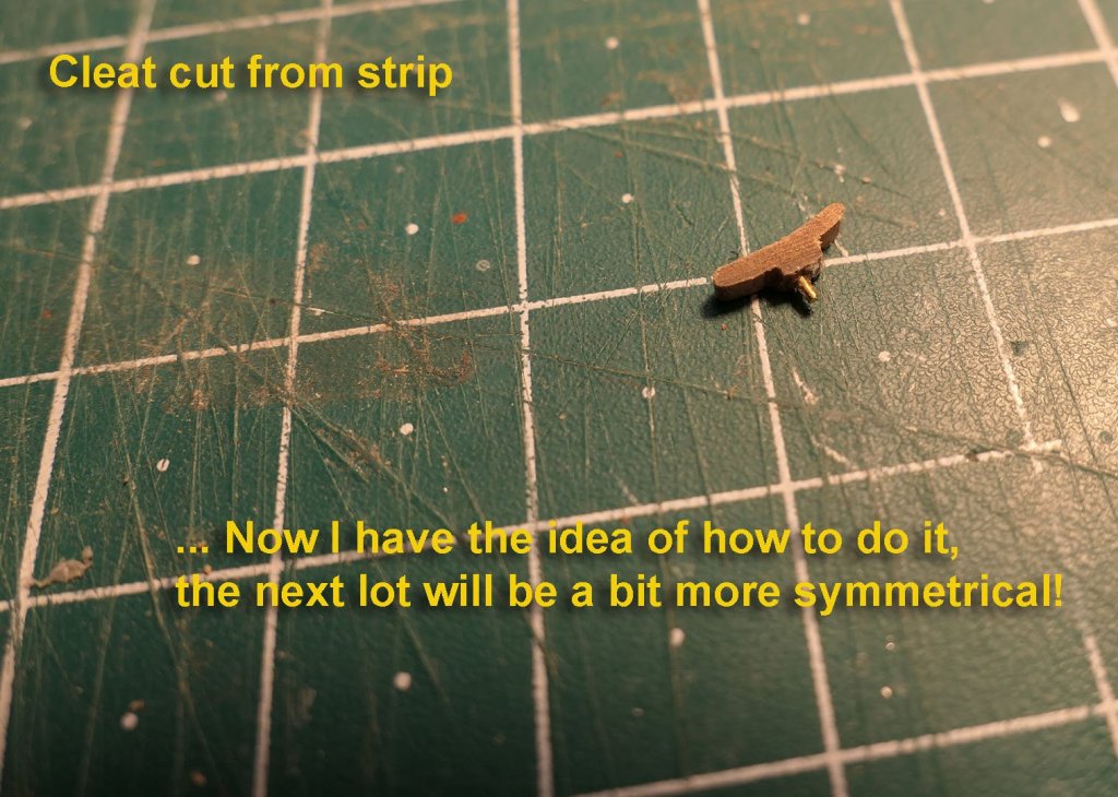
Cleats While I’ve been involved in other work, I’ve been pondering how to make the cleats. I read several other articles on this site and elsewhere, but wanted to do this in as labour-saving a way as possible. I eventually figured that the easiest way would be to start from the rear of the cleats by milling away the underneath of the two arms. I used my TurboCAD programme to draw up the outline for the strip to be milled, using the dimensions of the cleats shown on the plans. This was placed on a strip of pear wood 7x2mm in section, this being the overall face dimensions of the cleat. I left 0.4mm spaces between the cleats on the strip to allow for the width of my razor saw (0.3mm) -- you'll see this a few photos further down. After clamping the strip to the compound table I drilled the holes for the supporting pins at the back of the cleats. The backs of the cleats were then milled to a depth of 1mm on the 2mm thick strip. I then took the strip, and, holding it in a vice, sanded the underneath of the arms to a curve with a sanding stick. I then sanded the front faces of the cleats to a curve on an old bit of brass tube. I then inserted and glued brass rod into the holes on the backs of the cleats on the strip. As this was my very first attempt, it is all a bit rough. However, now I have the idea of how to do it, I’ll be able to perfect the technique for future belaying pins. I only need 14 of them for the chaloupe, so it’s no big deal. Tony


- 124 replies
-
- 13
-
-
- longboat
- Chaloupe Armee En Guerre
- (and 1 more)
-
I used square mini files or jeweller's files for the small square ports. They come very cheaply in sets of six or so on eBay, Amazon etc. You can also make your own square punches for smaller squares (e.g. on the windlass) by squaring off nails. Then there's the option of making your own mini-chisels 1mm or so in size using allen keys and suchlike. There's lots of advice on the web on how to do this. Tony
- 104 replies
-
- 4
-
-
- sherbourne
- caldercraft
- (and 1 more)
-
Thanks, Dane. Your work needs much more promotion in English-speaking sites, and I hope that other modellers with more experience than mine will take up the challenge of your intriguing and lovely kit. Tony
-
Thanks for the nice comments, druxey and G.L., and to all who posted 'likes'. That's the nice thing about logs. Every time I read someone else's log I, too, learn new things. Above all, they make me think, as well as wonder often at the ingenuity displayed. And thinking's the main pleasure of this game for me. It demonstrates that there can never be a simple guide to how it's done for any model, as so many variables will always intervene. Skill seems to me separate, and comes with practice and experience. Tony
- 124 replies
-
- 4
-
-
- longboat
- Chaloupe Armee En Guerre
- (and 1 more)
-
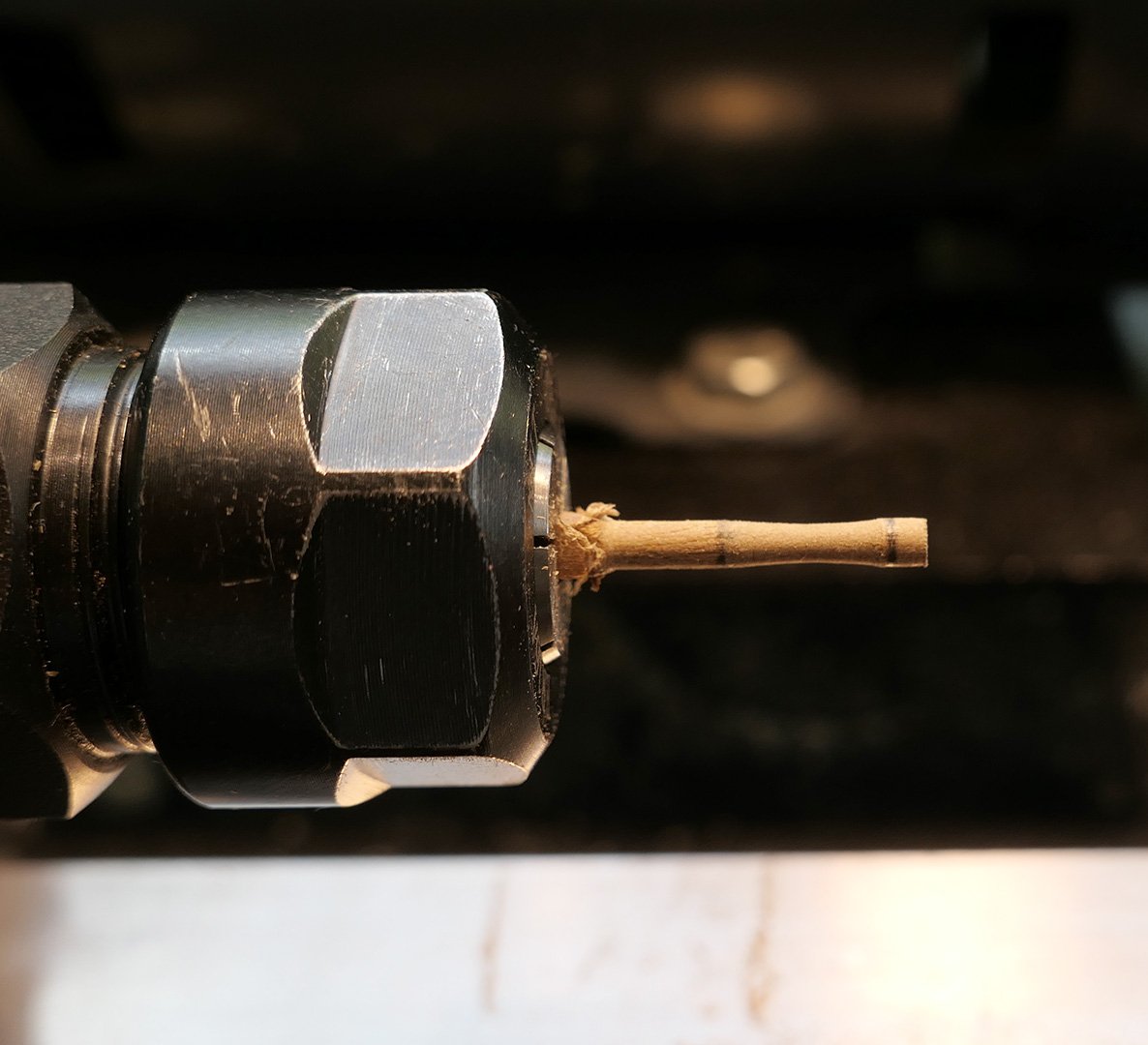
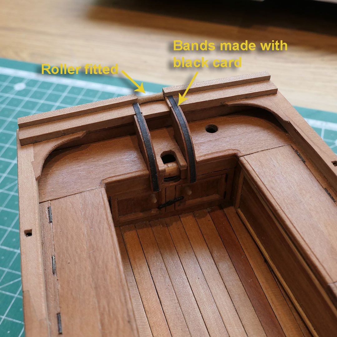
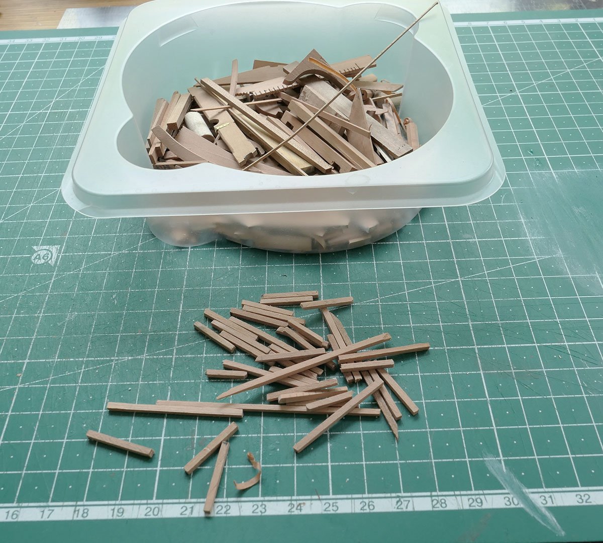
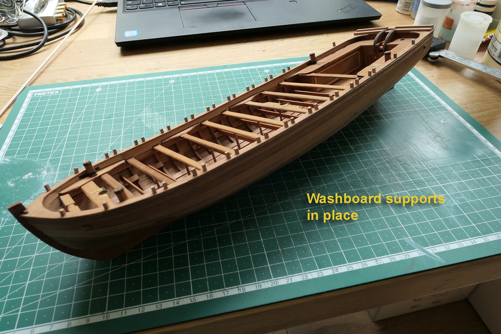
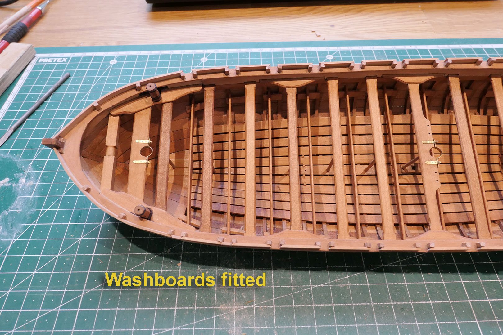
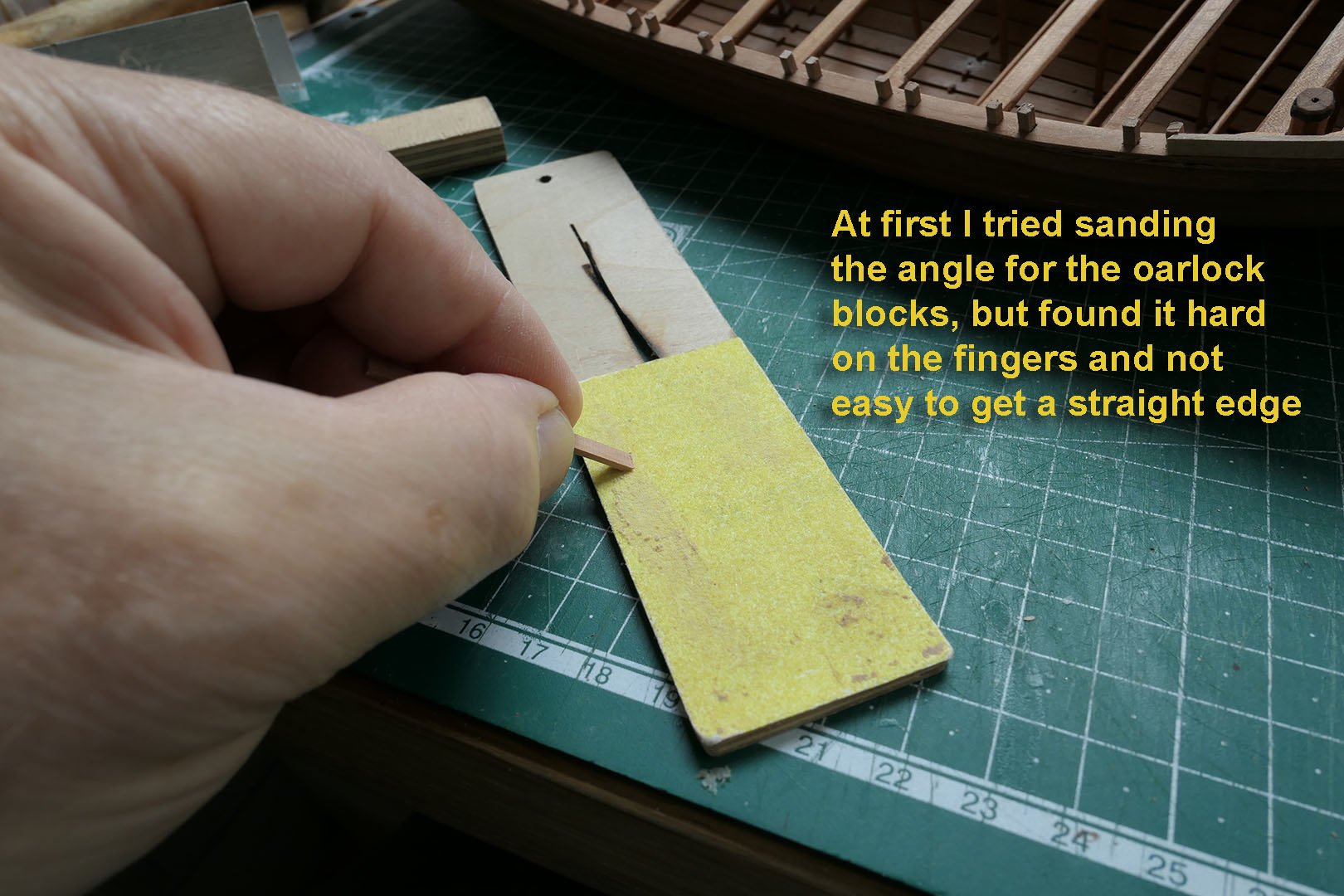
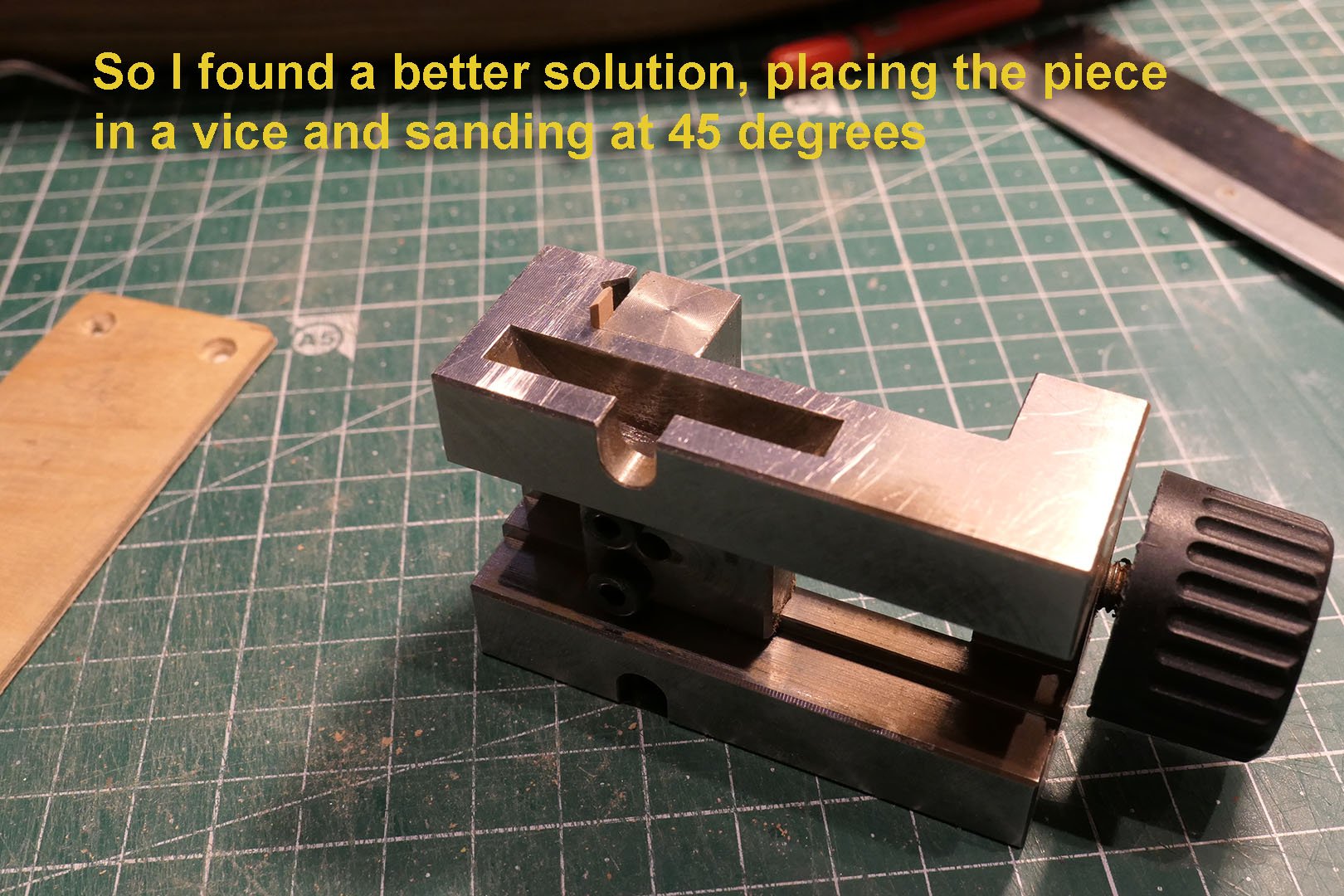
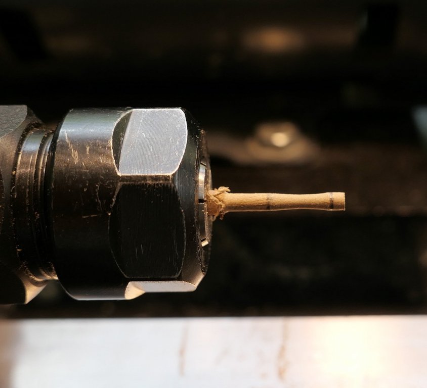
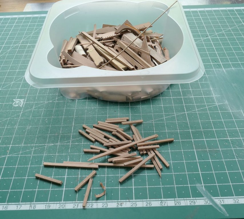
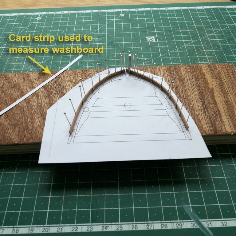
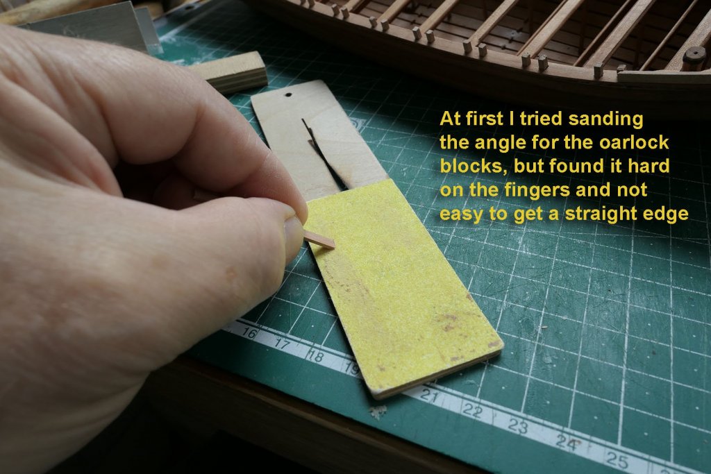
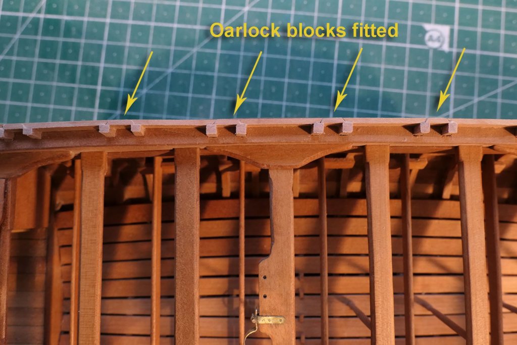
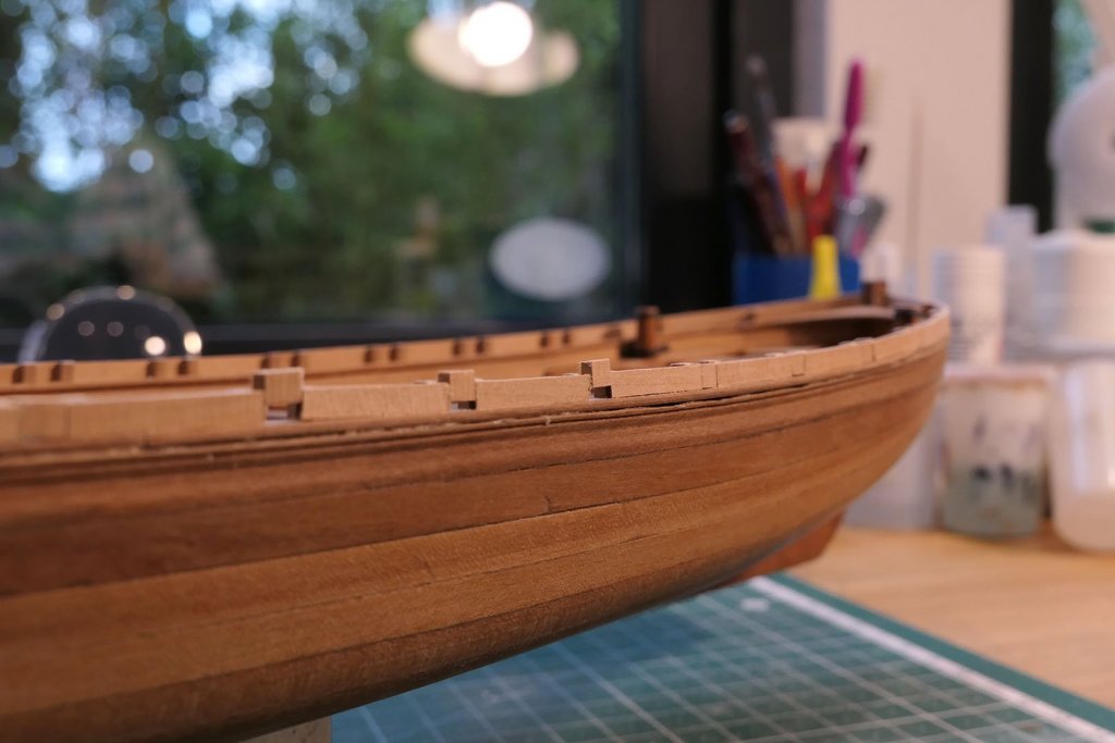
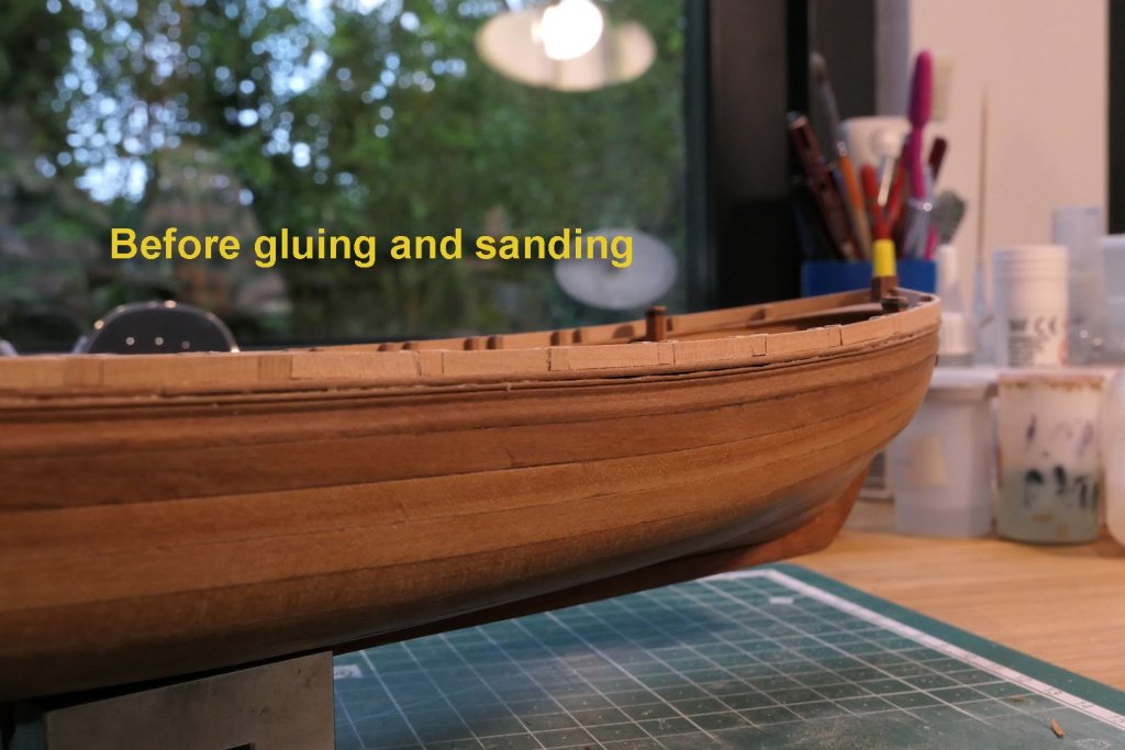
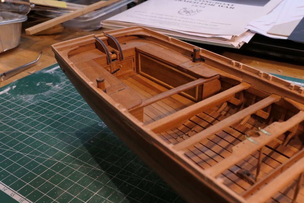
Rear Roller This was relatively easy to do. I cut a 3mm square length to a 2.6mm rod on the lathe, then tapered the central area with a file It should be noted that the roller is not fitted in line with the transom top timber, but between that and the transom. Ideally, a little axle would be fitted, but I just cut the roller to size and glued it in the appropriate position since the axle would be impossible to see and I wouldn’t want people to start rolling it just to prove a point. Washboards I had a nice load of offcuts from the 2x2mm frames which could be used for the washboard supports. The washboards at the bow needed bending, so I laid the wet cuts on a jig. I then had to build the blocks for the oarlocks. This proved to be a little tricky. I started doing it by hand, but this was hard on the fingers and didn’t produce a straight line easily. I soon found the answer with a vice. This turned the process into something very rapid indeed. Next up will be the bow roller, followed (I hope) with a whole load of the hull fittings for the rigging. This may take a while as I am involved in other work for the moment which is very time consuming. All the same, keep watching this space! Tony


- 124 replies
-
- 20
-
-
- longboat
- Chaloupe Armee En Guerre
- (and 1 more)
-
Looking forward to this build. I like your Ballahoo. Tony
- 104 replies
-
- 2
-
-
- sherbourne
- caldercraft
- (and 1 more)
-
Thanks, Moab. That's a nice compliment. I do like these longboats and inshore craft too. I use TurboCAD DeLuxe 21. It was about £30 when I bought it. I can't really give an opinion on the learning curve. I did spend time looking at the tutorials on the web and asking questions on the TurboCad forum. My approach was to define the problem I needed to solve (e.g. loading a jpg, or tracing, or drawing a curve) and looking up how to do it. As a result, I found the process painless and cumulative. That way you don't have to set about learning everything at once. There's a wonderful set of tutorials on YouTube by Paul Tracey at https://www.youtube.com/playlist?list=PLbIC1X9V7KK9ayIcOfzdYm0h1AQOOTSKa, which I strongly recommend. I've tried quite a few CAD programmes, but the one I keep coming back to is TurboCAD. Other programmes might suit you better. You can do quite a lot with a photo-editing programme such as Photoshop, or an illustration package. If you work in Linux, there's Gimp and FreeCAD. I hope this helps, but if you want to know more, don't hesitate to ask. Tony
- 124 replies
-
- 3
-
-
- longboat
- Chaloupe Armee En Guerre
- (and 1 more)
-
Thanks very much, Paul and Karl. I'm beginning to feel improvement in being accurate in my cutting. I just wish I'd been more careful with the start of the build, but then that's how we sometimes have to learn. I especially love the feel and look of the wood and the boat itself. Paul, I very much liked the pictures of your earlier Cutty Sark. That's a model I made from the Revell plastic kit when I was a teenager, and the memory of that stimulated me to think of taking up wooden ship modelling in my retirement. Your longboat, too, is beautifully finished. Karl. you'll see that I've posted a link to your absolutely superb build of the Chaloupe at the beginning of this log, and I am simply amazed at the level of craftmanship and precision you bring to all your builds, so I'm even more grateful that you give me a kindly nod in my early and novice attempts. Builds of such beautiful workmanship serve as great ideals towards which I can strive. Tony
- 124 replies
-
- 3
-
-
- longboat
- Chaloupe Armee En Guerre
- (and 1 more)
-
The simple way to obtain the length of the rope would be to pull your cannon as far back as you want and measure the resulting length. Tony
- 84 replies
-
- 2
-
-
- sherbourne
- caldercraft
- (and 2 more)
-
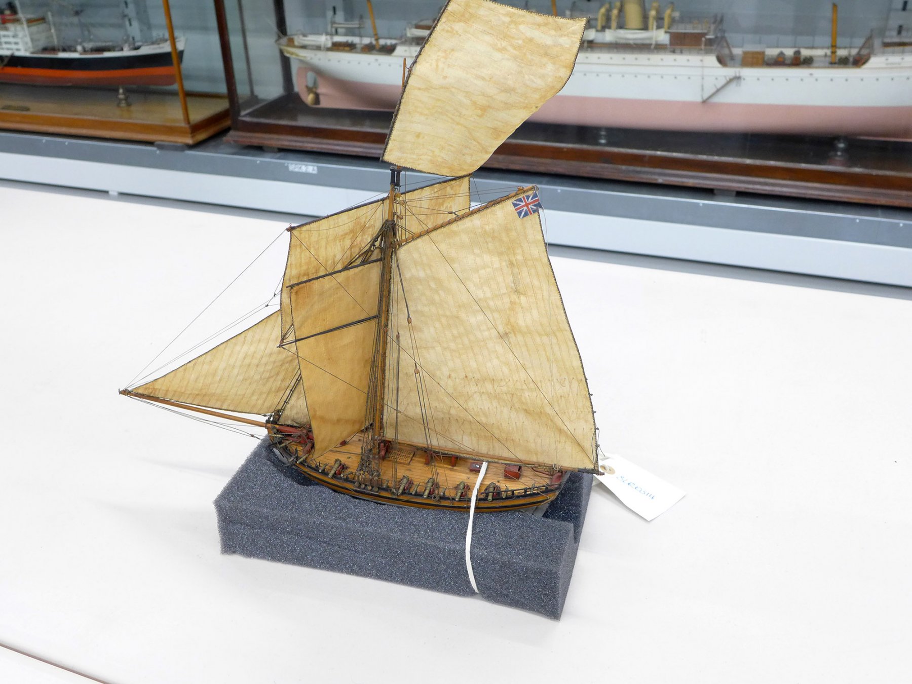
Just to add to Druxey's comment, have a look at these photos of the cutter Hawke I was shown in the Chatham Historic Dockyard (the same Hawke, I think, that was shown in a better state in the AOTS book on the Alert). The curator thought it must have been the result of a handler knocking the model against something and then hurriedly trying to 'repair it' in what he thought was the correct way. He groaned when he saw it brought from the store. However, I don't think anyone seeing this would think of it as historically accurate because of being contemporary. You can see the remaining photos in the gallery at Tony

-
I agree with Frankie that there are many inaccuracies in Petersson's book. However I found it invaluable as a simple guide to the names and principles of rigging. The reason is that it separates each aspect and its function which, for a beginner who has never sailed, is really helpful. Of course, as soon as I started rigging I went to Steel and Marquardt as well as others to make it more accurate, and I received really helpful criticism on this forum when I made mistakes, but without this beginner's guide I would have been lost in the complexity of drawings and explanations that are so often provided. Tony
-
Thanks, ragove. If you search for 'CARD' in the scratch building forum, you can see what can be done using card for ship models. Try Doris' posts, as well as GrandpaPhil, Ab Hoving, Chris Coyle, and several others. Then there's lots who do wonderful kits from card in the kit building forum. They're all way ahead of myself and their builds stimulated me to try a card model just to see how it is done. I might well come back to it once I've improved my skills on wood. I don't want to reach ahead of myself! Tony