tkay11
-
Posts
1,829 -
Joined
-
Last visited
Content Type
Profiles
Forums
Gallery
Events
Everything posted by tkay11
-
 Gosh, Johann! I feel a bit embarrassed as I admire and have followed your amazing work for a long time. I have learnt a lot from you. So thank you! Tony
- 124 replies
-
- 1
-

-
- longboat
- Chaloupe Armee En Guerre
- (and 1 more)
-
Thanks Dirk, G.L. and Moab. Much appreciated. I'm beginning to like this model more and more. I certainly see the advantages as well as the different difficulties of taking on not only this method of construction but also of a large scale longboat. The details are going to be quite challenging, although challenging in a new way because each part is that more obvious. One of the challenges I'm looking at right now is the construction of the stern sheets and getting them at the right height and angle. I'm also thinking of the ironwork to come, as well as (if I dare take it on) the rigging and masting for which I have the supplementary plans. Definitely a model to recommend as something that's elegant as well as setting new types of problem for the novice builder. Tony
- 124 replies
-
- 4
-
-
- longboat
- Chaloupe Armee En Guerre
- (and 1 more)
-
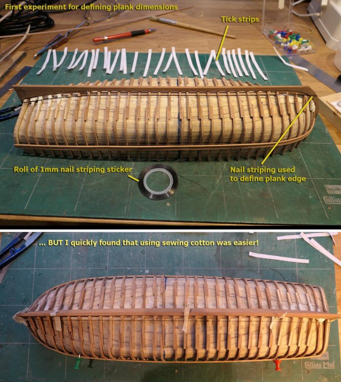
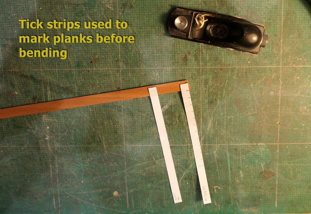
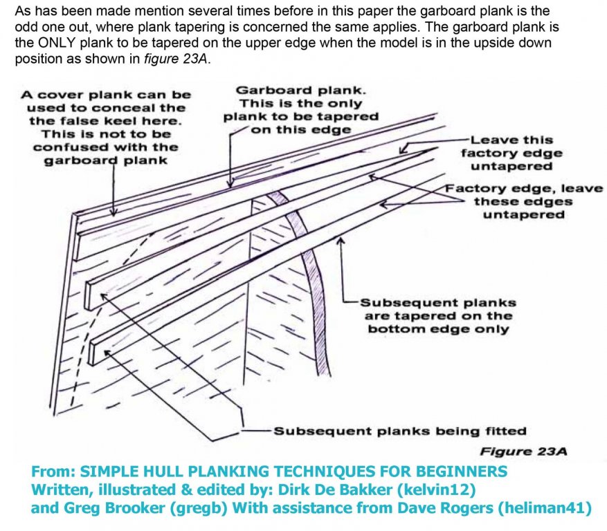
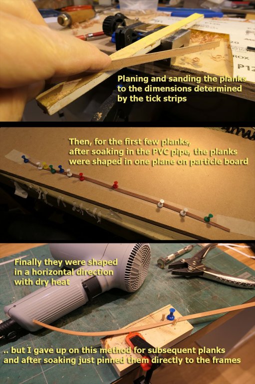
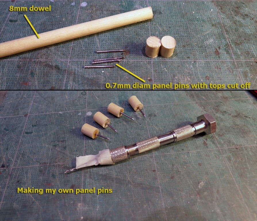
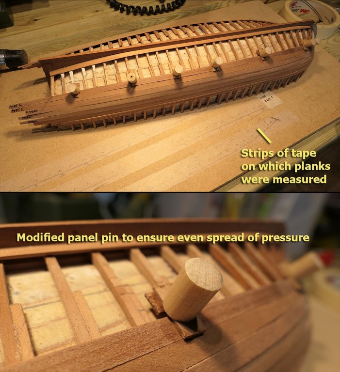
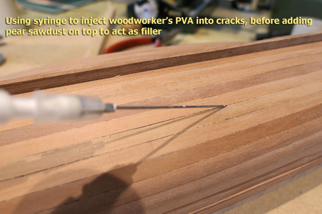
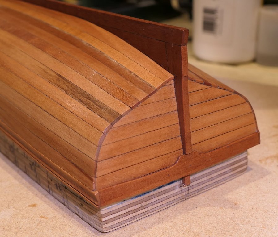
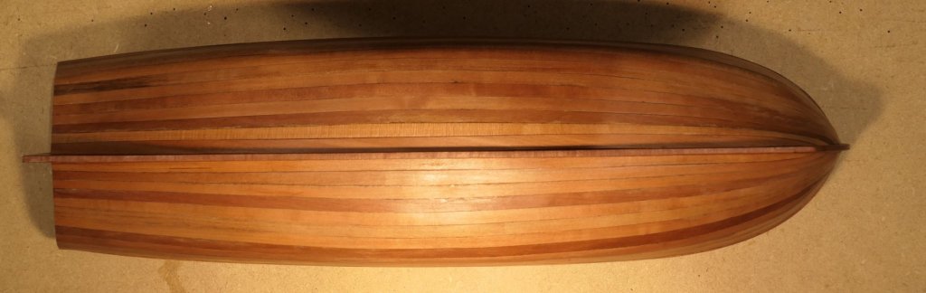
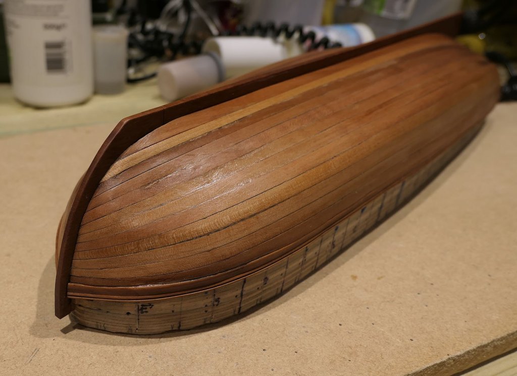
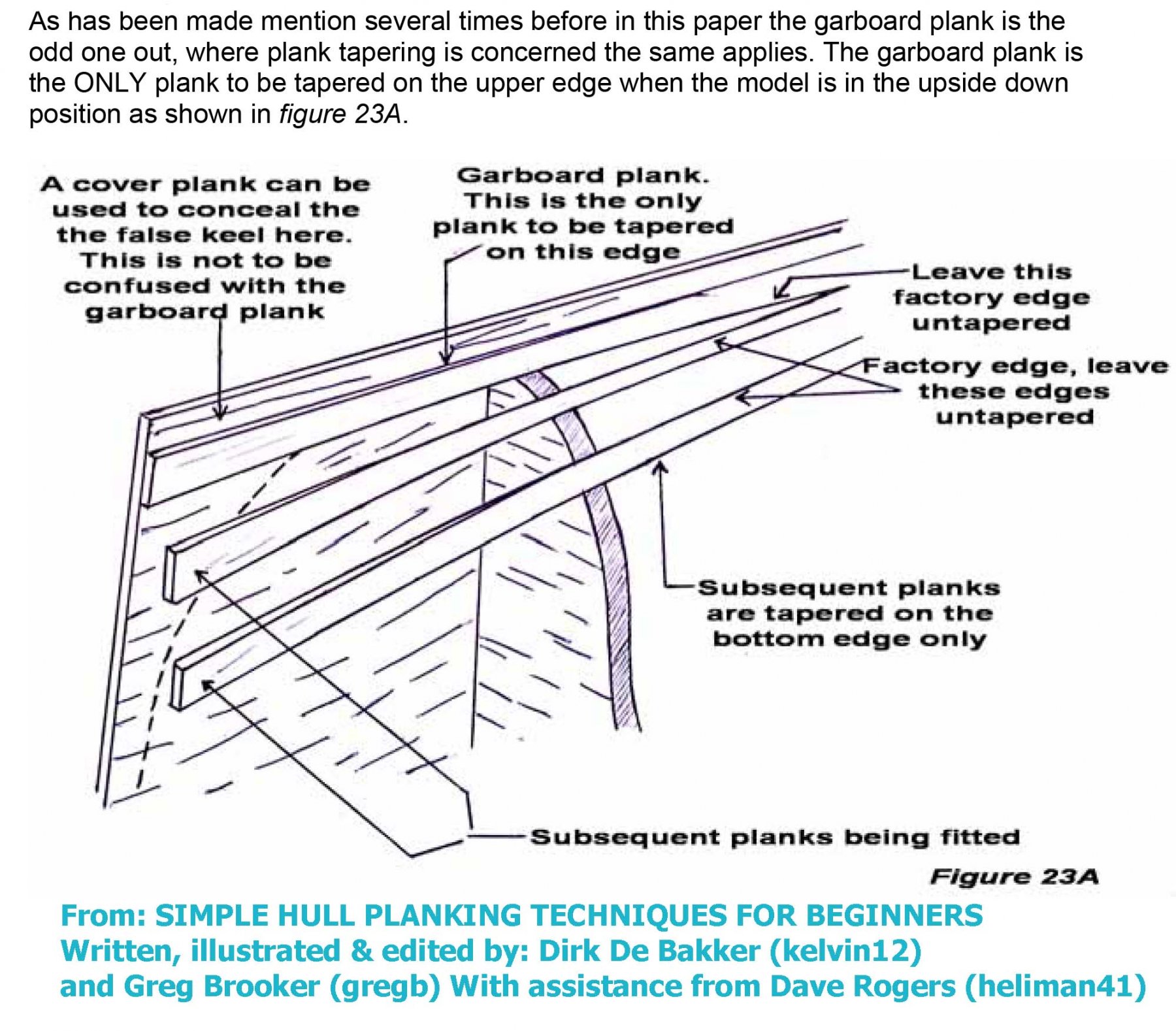
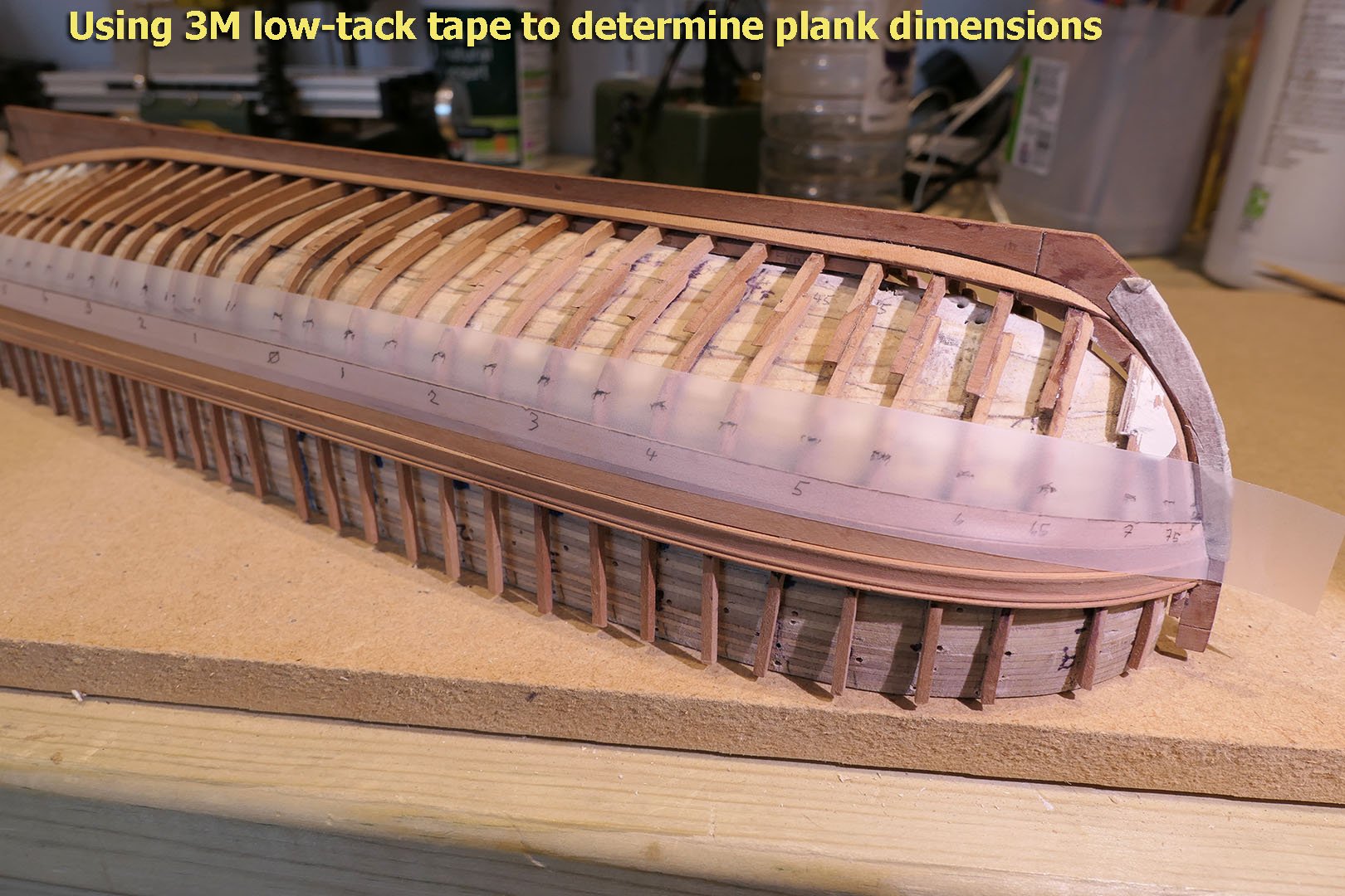
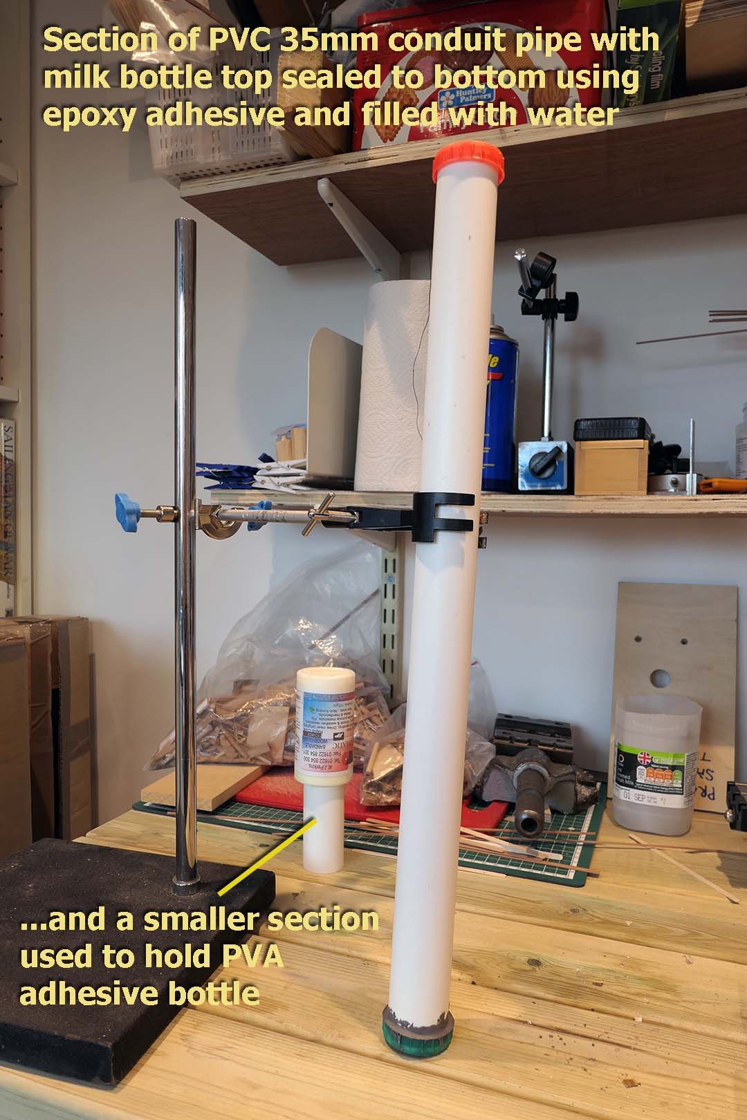
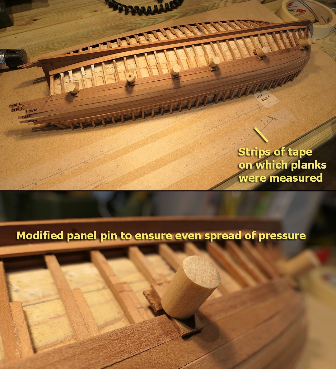
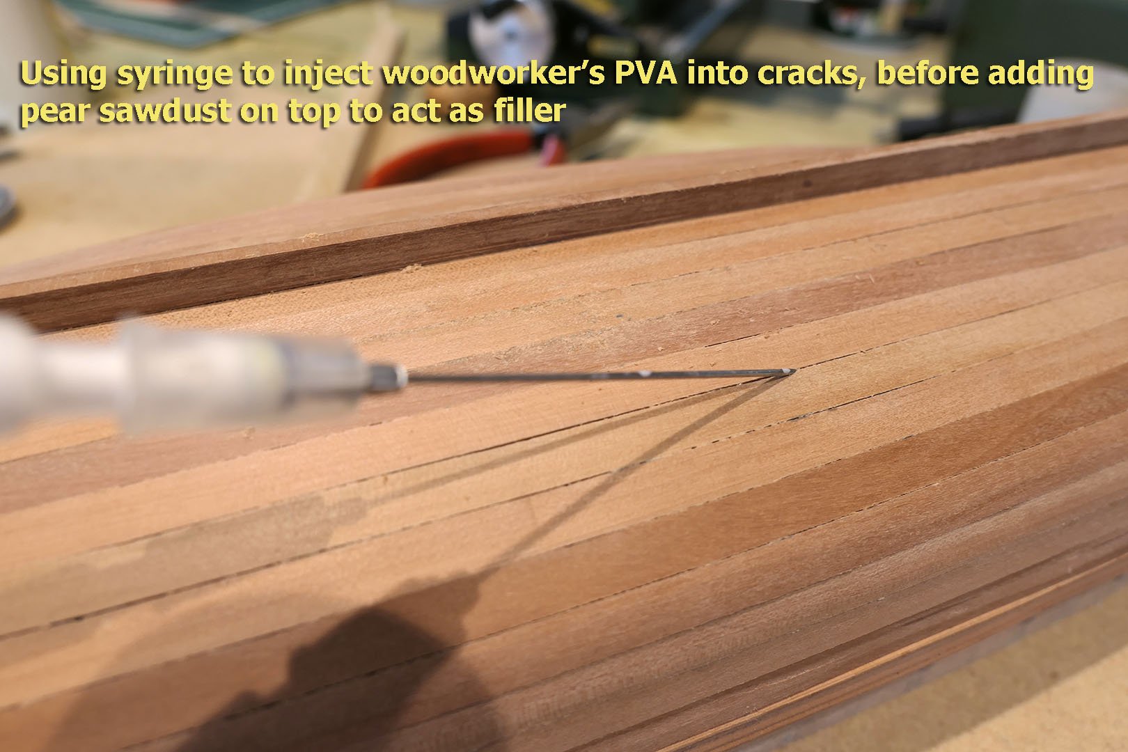
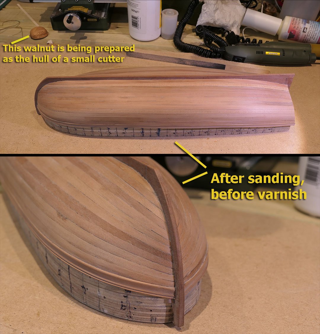
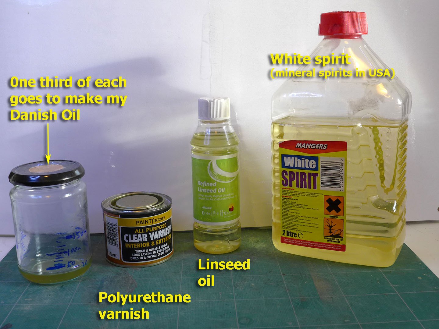
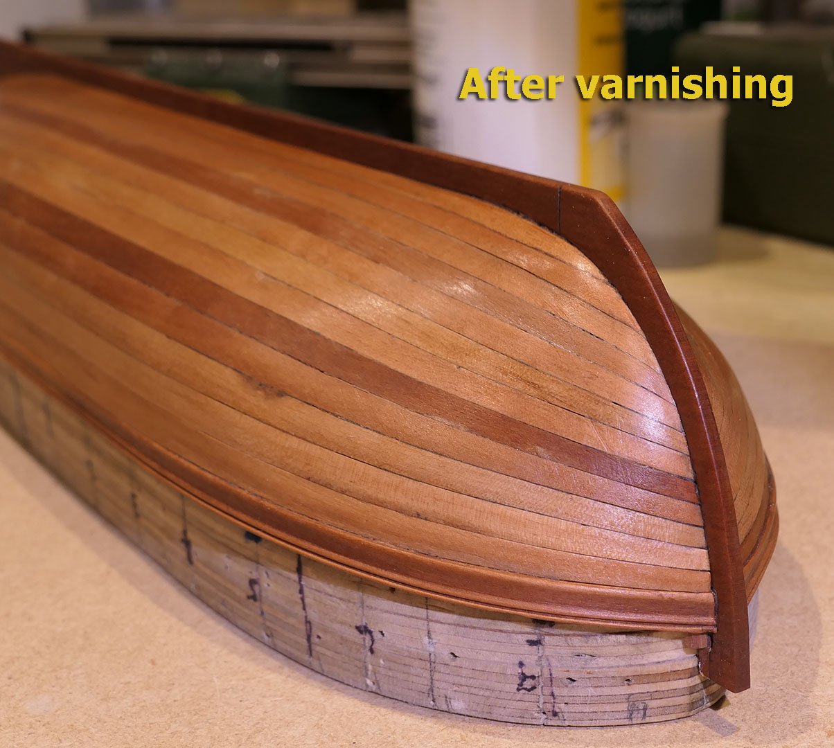
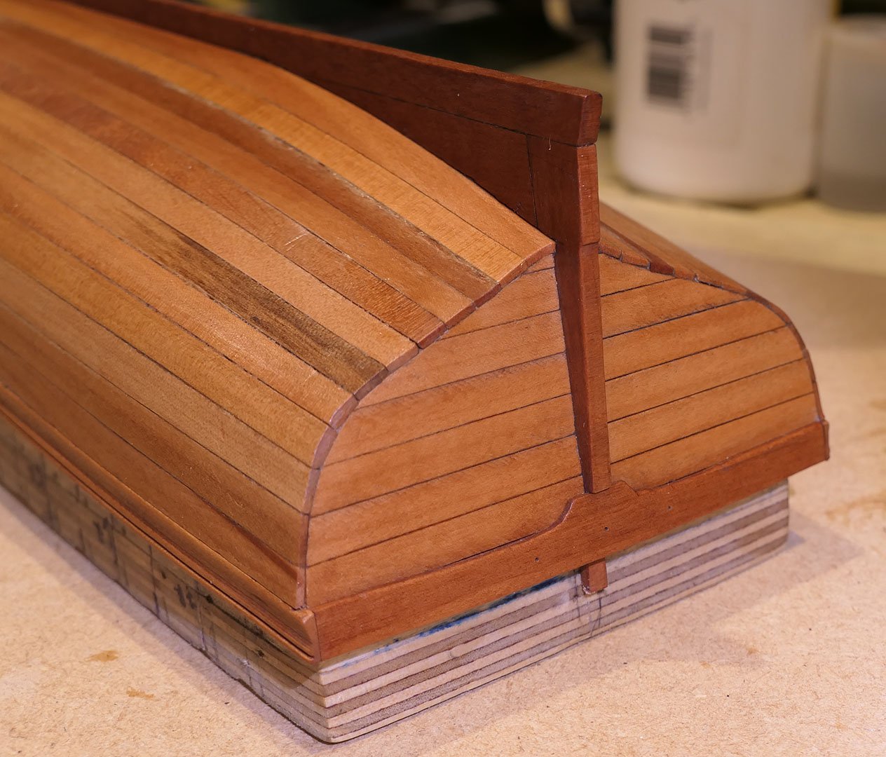
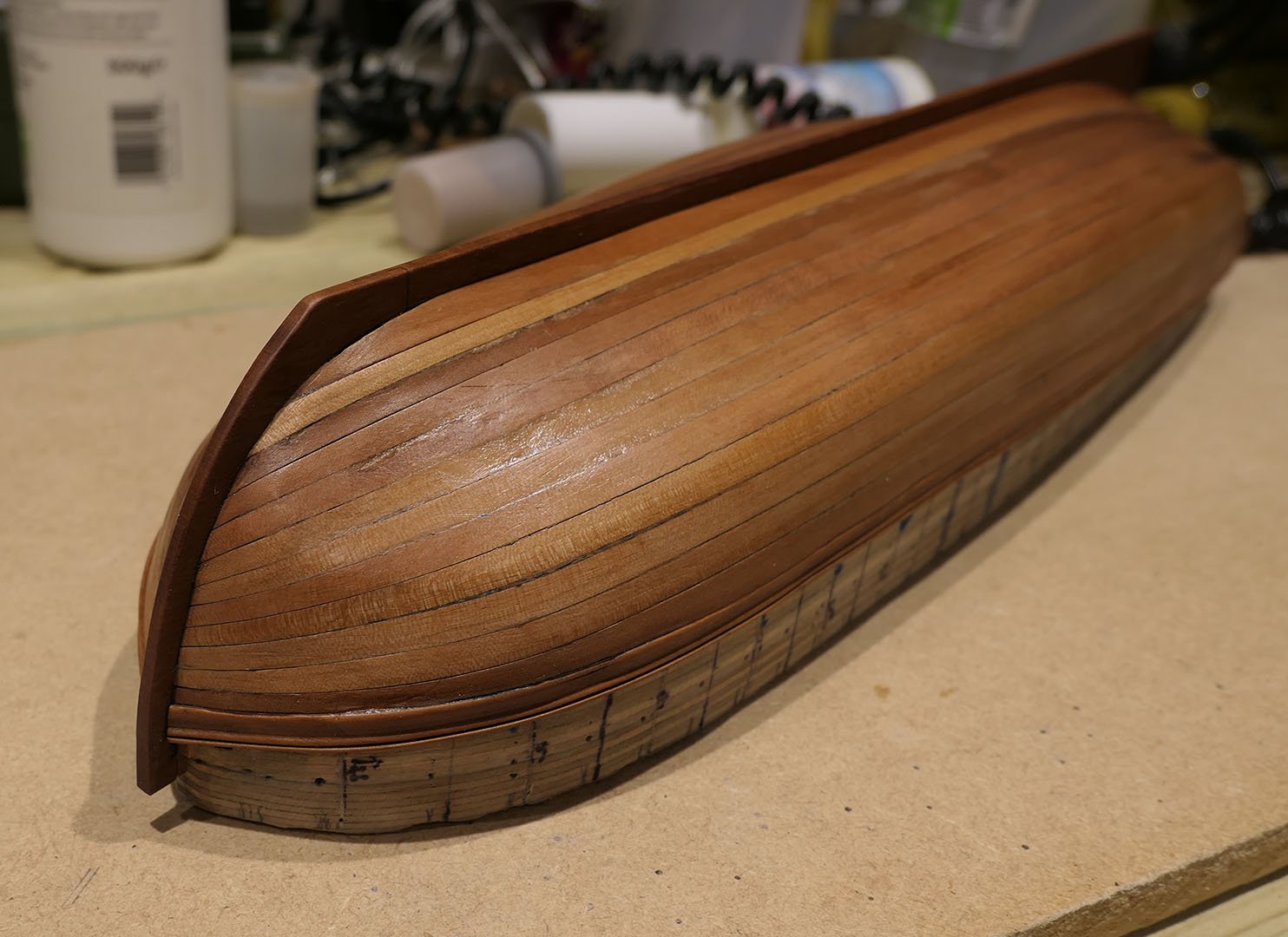
External Planking You will remember from an earlier post that I had raised the question of how long the external planks would have been. A number of sources have shown that originally there would have been about three planks of 12ft for each strake, with normal butt sequencing. I could have tried to do this, but with the frames at only 2mm wide it would have been tricky to get the butts and fixing done well. Also I could have simply scribed where the butt joints would have been. I might try to do this at some time, but for the moment I am following what others have done with this model and just lined the hull with full length planks. This itself has implications for the preparation of the planks. We can now get back to the fact that I had not ordered wide sheets of 1mm pear wood for the planking, but instead had bought strips 6.2mm wide. This meant that I could not practice spiling, as I was not going to waste all that wood and pay another £15 for delivery. And so I had to experiment a lot in order to find the best method of shaping and fitting the planks. Of course, whether I would spile or not, I had to get the marking out correct. I used the time-honoured method with paper tick strips 5mm wide, along with the Chuck’s planking fan diagram that is available on the forum at http://modelshipworldforum.com/ship-model-framing-and-planking-articles.php for lining off the hull. The tick strips were used for all those frames that reached the keel after the stem, notably frames 6.5 backwards. To find the forward edges where the planks meet the stem I first used 1mm finger nail striping that you can find for about £1 on eBay. However, I found quickly that the more traditional method of using sewing cotton worked even better. Each plank was then shaped before bending using a miniature plane and filing sticks. The garboard planks were laid first, with their tapered edges at the top (to meet the untapered edges of subsequent planks). This is as shown in the file SIMPLE HULL PLANKING TECHNIQUES FOR BEGINNERS also available in the downloads section on planking in this site. Finding the shape of the planks I used Chuck’s idea of low-tack transparent tape to find the shape of the planks. This worked better than standard tape because it takes pencil marks far better. Dry heat versus soaking I tried very hard to bend the planks just using a hair dryer and a variety of jigs. However, the planks are very long (340mm) and the complexity of the curvatures made it very tricky to do this. In the end I decided (as many others have done, and as is recommended in the booklet for this model) to use a combination of soaking and heating with the hair dryer. First, the soaking. For these long planks, I followed the example of others in using a section of 35mm diameter PVC waste pipe, using a milk bottle top sealed at the bottom end with an epoxy adhesive (JBWeld). I then soaked the planks overnight, and laid each one flat over the shape of the plank on low tack tape on some particle board using panel pins to follow the shape. I helped them to dry with the hair dryer, but waited a while until they had fully dried out. To bend the planks horizontally, I then used dry heat. After laying three planks in this fashion, I thought I’d experiment with soaking the planks and then fixing them straight to the frames, letting them dry fully to ensure they shrank back to their dry sizes, and then gluing the dried planks to the frames. This worked very well indeed, and much better than going through the palaver of trying to shape them before fixing to the frames. Fixing the planks to the frames I had thought to use ordinary mapping pins to fix the planks to the frames and the mould underneath, but found that the pins were too short for the combined thickness of planks and frames. For a while I looked at the possibility of making framing clamps with screw threads, but in the end opted for making my own panel pins with 8mm dowel and standard metal panel pins with the heads taken off using a cutting disk. I then added strips of wood to ensure the even spread of pressure on the planks across their width and to prevent indentation of the planks (which was only partially successful, as will be seen). Inevitably there were some hairline gaps in some areas between the planks. Initially I used a syringe to fill these with woodworkers glue (the white, not the yellow variety) followed by a sprinkling of pear wood sanding dust to make a similarly coloured filler. However I found that it was just as effective to add the glue by itself for the very finest of gaps. With all the planks in place I then sanded with a combination of sanding blocks, sanding sticks, and a Proxxon pen sander. This was followed by scraping using a Stanley blade, and finally steel wool. As you will see, there were still a few blemishes and indentations, and certainly not up to the standard of others who have built this model, but as I’m using this model to learn I am not going to start all over again. As the walnut inadvertently crept into the picture, I might as well explain it. I had made a small gaff-rigged cutter for the grandchildren with half a walnut shell providing the hull. It had sails that could be raised and lowered, but no rudder. This proved very successful, especially as it floated, so I am about to build a few more of these miniature cutters for them. Varnishing As with my previous build, I made my own Danish oil from a mixture of linseed oil, white spirit and polyurethane varnish mixed in proportions of one third for each. The results with the varnish are: Some of the imperfections you see are due to irregularities in the framing which are entirely due to my failing to align them correctly. I put this down to learning for future builds. Next I’ll be going to the inside and working my way deeper into the dark side. Tony


- 124 replies
-
- 26
-
-
- longboat
- Chaloupe Armee En Guerre
- (and 1 more)
-
Another way to make shackles
tkay11 replied to vaddoc's topic in Metal Work, Soldering and Metal Fittings
Another possibility might be a modification of the approach I used for making swivel gun mountings when building the Sherbourne. I took a brass rod, bent it to a U, flattened the ends with a cutting wheel, then laid a brass tube across the top and finally cut out the middle section of the brass tube. You can see the process if you scroll down to "Swivel Guns" in the section at https://modelshipworld.com/index.php?/topic/335-hmc-sherbourne-1763-by-tkay11-finished-–-caldercraft-–-scale-164-a-novice’s-caldercraft-sherbourne/&page=4&tab=comments#comment-117947. I agree it may be a bit fiddly for shackles, but it may stimulate some inventive thinking by someone! Tony -
And a warm welcome from North London! Looking forward to your posts! Tony
-
Was the 4mm difference the measurement at 1:12, at 1:24 or at full scale? In the drawings of the Chaloupe Armée and of Le Rochefort, for example, I found similar small discrepancies between plans, but they would not be noticeable in actual builds. Similarly it is sometimes difficult (though possible) to establish inner and outer lines for the frames as they have to be calculated in the case of the Chaloupe. Problems will be greater when trying to use the drawings as the basis for 3D constructions in CAD. I don't know the plans for the Catarina but it looks like an attractive build. Perhaps you could contact M.Fissore about your problems as he has clearly built the boat very nicely. I have found the authors of these monographs to be very helpful in dealing with problems of this nature. Another possibility is to start a discussion in the French forum Marine & Modélisme d'Arsenal where there are often discussions about difficulties with the plans from various Ancre monographs.
-
Thanks a lot, Moab and Michael. You've reinforced the value of build logs to preserve the spirit of this forum. They help the builder as well as others. Even if I don't finish it, it's the steps along the way that are meaningful. After all, without those there would be no model! Tony
- 124 replies
-
- 3
-
-
- longboat
- Chaloupe Armee En Guerre
- (and 1 more)
-
Hobby/micro drill press suggestions
tkay11 replied to bigcreekdad's topic in Modeling tools and Workshop Equipment
That looks pretty effective. On mine I had to put a wedge between the drill holder and the support on which it revolves because it was very slightly out of the vertical. Is yours ok in that regard? I've enjoyed modifying mine as well. You can see all my mods to make it a mill in my build logs if you're interested.I Tony -
There's also the Taig/Peatol lathes. I have a second hand one and it works really well. In the US the micro-lathe (the one I have)with some tools starts new at about $450, without tools for $380. There's a great deal of information on how to use them on the web. A particular advantage is the way the tailstock can handle drilling by moving the chuck with a lever. I bought mine for £300 from eBay with a large number of tools and cutters, which I thought very good value. Their mills are good too. I use mine both for wood and brass. You can see the Taig lathes at http://www.taigtools.com/ and the microlathe II at http://www.taigtools.com/mlathe.html. Tony
-
How nice to see these builds continue, Gregor. As usual, beautiful work. What process and materials did you use for the stove, wheel and pumps? Tony
- 121 replies
-
- 2
-
-
- la jacinthe
- schooner
- (and 2 more)
-
A quick search on Google for 'wrap to a surface in turbocad' shows answers that seem to agree with Pat's suggestion that this can only be done with the Platinum version. e.g. https://forums.turbocad.com/index.php?topic=18161.0 It's very expensive (£1000) to upgrade if were to do it from my ordinary version of Turbocad 21! Tony
-
I don't know if this helps, but during my build of the Sherbourne I had a query about Petersson's illustration of the mast tackles, or what he referred to as the Burton pendants. As you say, he has three pairs of shrouds on each side which should make for 6 deadeyes if that was his intention and if you look carefully at the illustration with the mast tackles there is one block for the tackles on the port side near the mast head but without the remaining tackle, whilst the tackle on the starboard side is shown ending on a belaying pin and a ring. I found his illustrations confusing because as you note he has varying numbers of shrouds as well as being confusing about the tackles. I don't think the number of shrouds matters as Steel in his section on the rigging of cutters says "SHROUDS, four or five pairs, are fitted and got over the mast-head, similar to those in ships. The after shroud on each side is wormed, parcelled and served with spun-yarn, down to the deadeye." In relation to the mast tackles, I followed Marquardt's illustration as you can see in the discussion at: You can also see how I approached it in my build log at https://modelshipworld.com/index.php?/topic/335-hmc-sherbourne-1763-by-tkay11-finished-–-caldercraft-–-scale-164-a-novice’s-caldercraft-sherbourne/&page=8 Tony
- 714 replies
-
- 2
-
-
- lady nelson
- victory models
- (and 1 more)
-
Thanks, Dirk. I was just about to comment on your great build of the Maria -- the pictures of which just came up in my MSW digest. As usual I am in awe of your skills. And I'm delighted that you can still spend time to keep a friendly eye on my builds! Tony
- 124 replies
-
- 1
-
-
- longboat
- Chaloupe Armee En Guerre
- (and 1 more)
-
Thanks, Nils, for the kind words. I'm not sure it's a tutorial, though. More just a detailed explanation of what I have chosen to do so that others can assess when building their own models or comment if they feel there are better ways. I'll admit, though, to that little gasp of pleasure people experience when they take the hull off the mould and see it all stick together as a skeleton. Skeletons have their own attraction. Now to see if I can breathe some life into it! Tony
- 124 replies
-
- 2
-
-
- longboat
- Chaloupe Armee En Guerre
- (and 1 more)
-
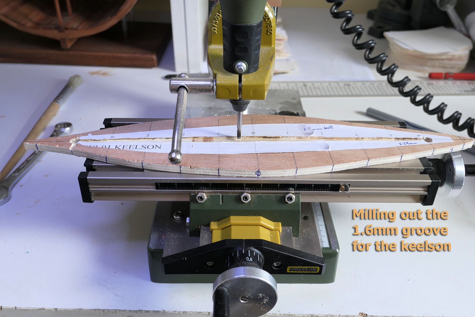
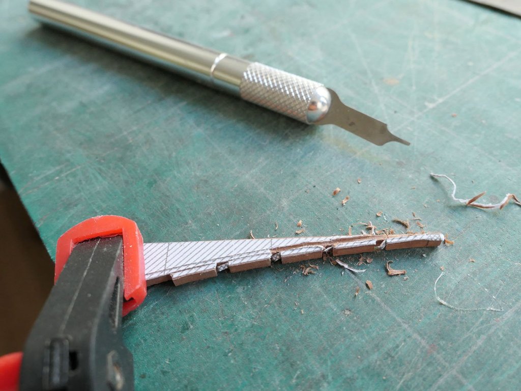
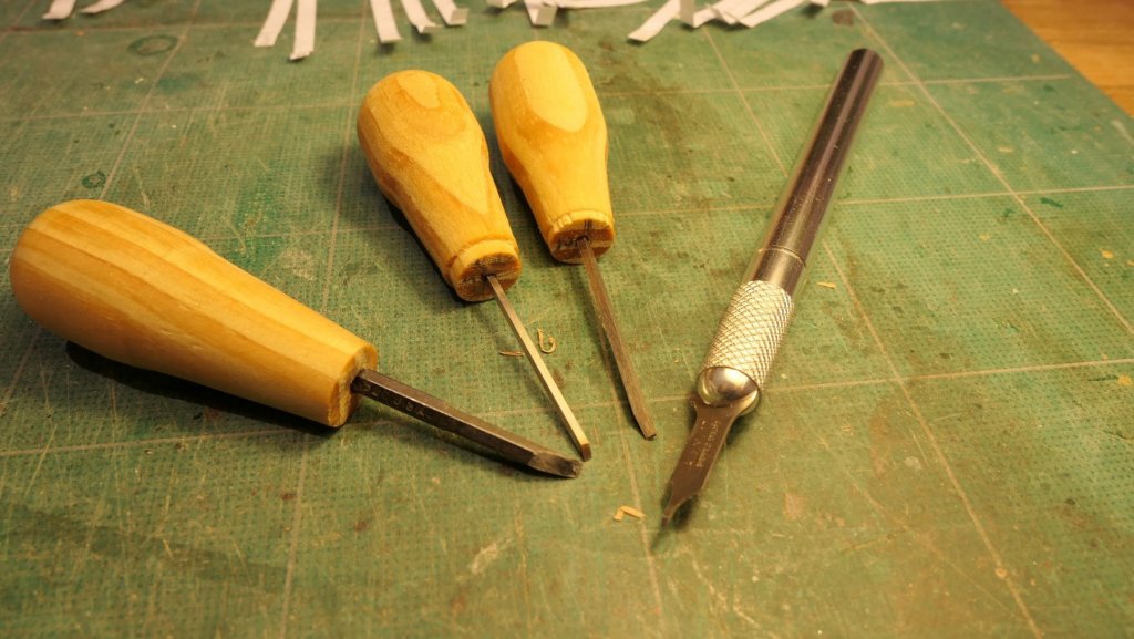
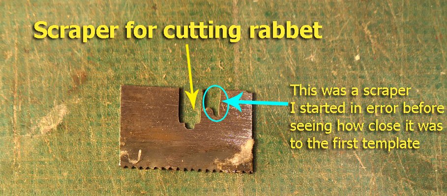
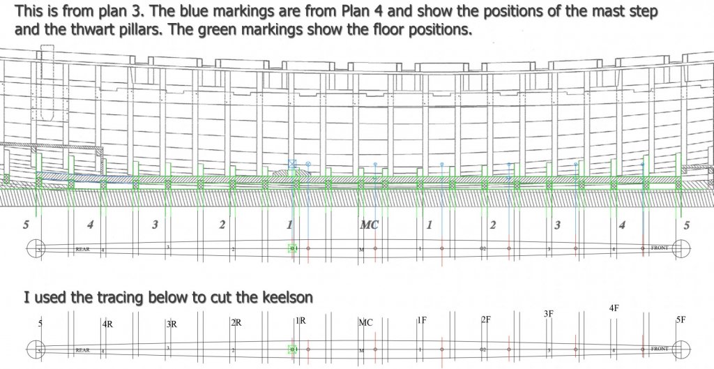
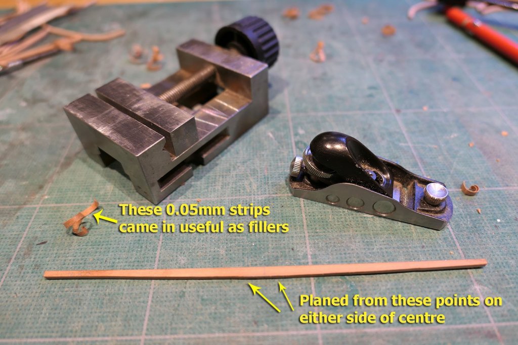
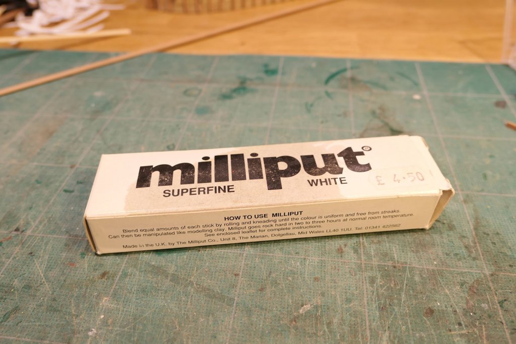
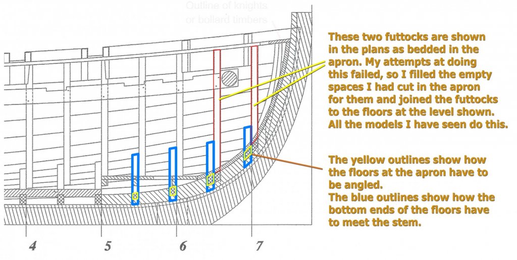
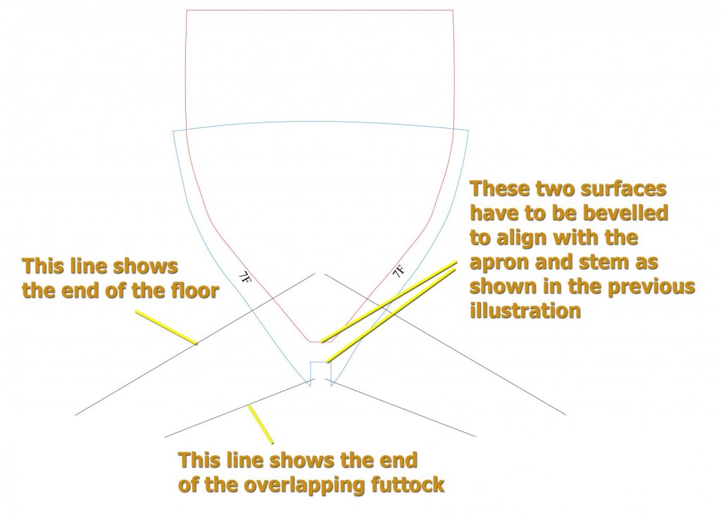
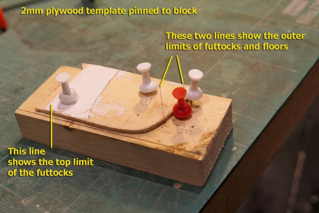
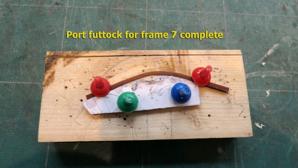
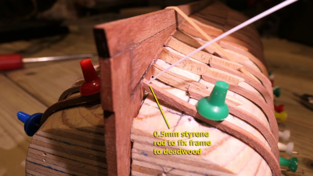
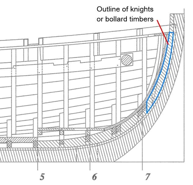
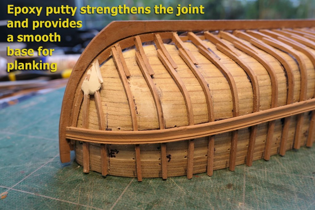
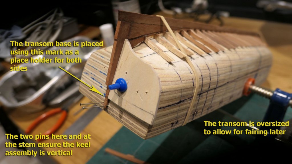
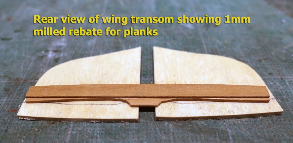
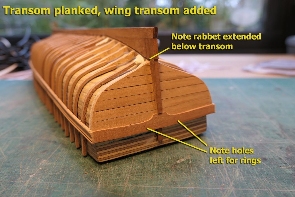
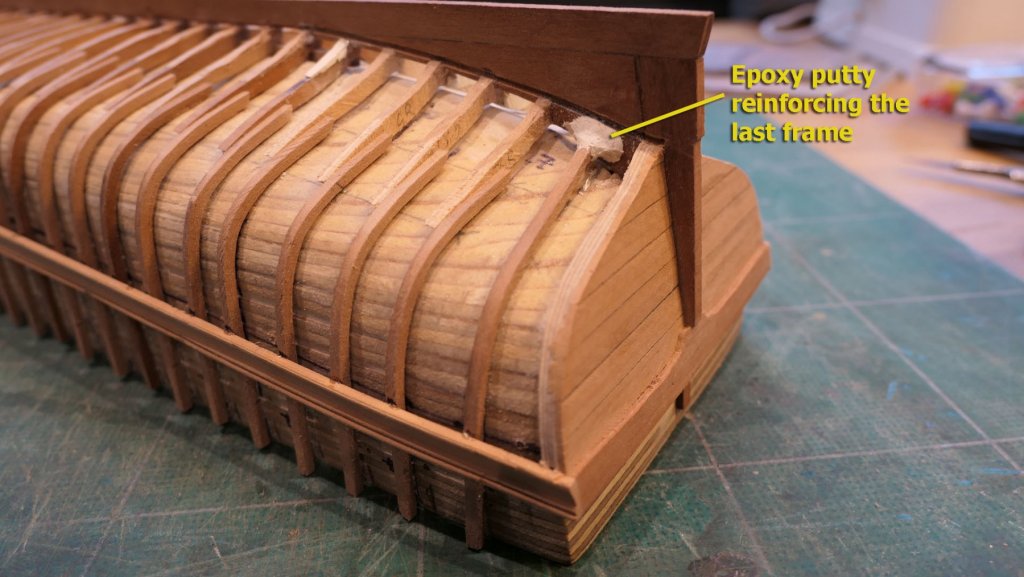
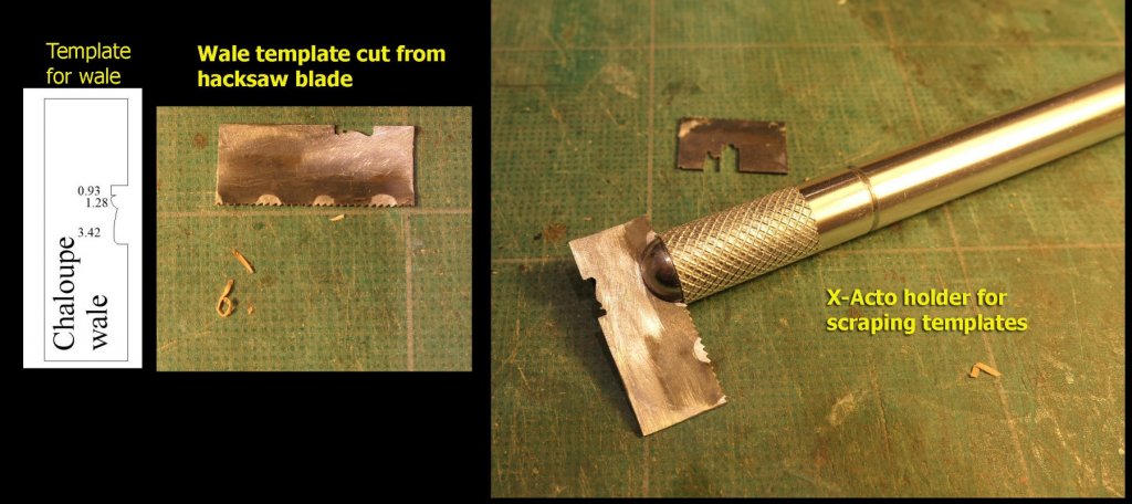
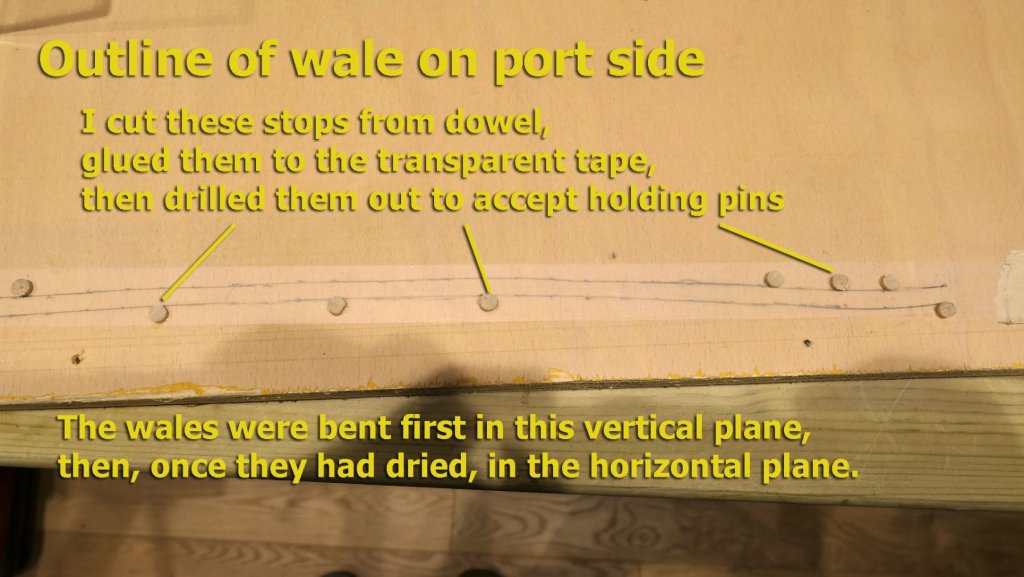
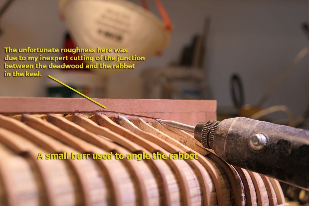
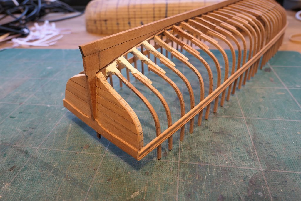
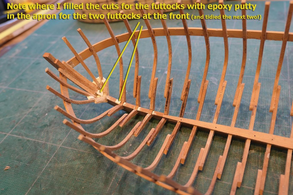
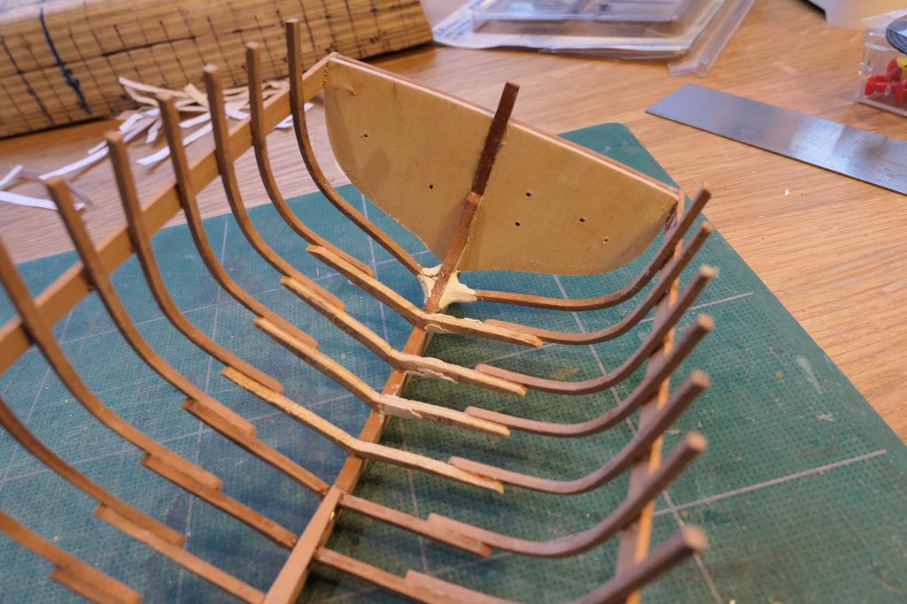
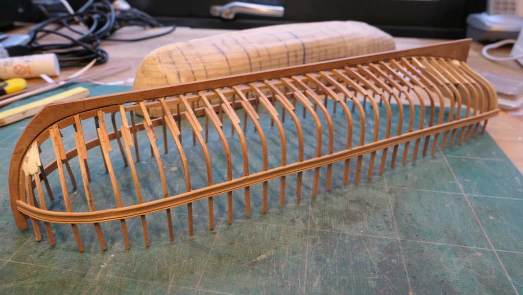
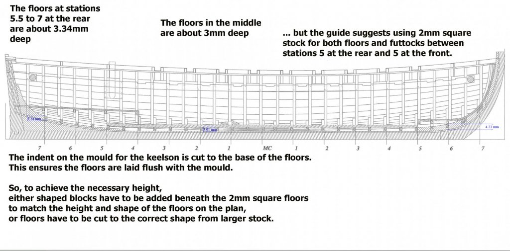
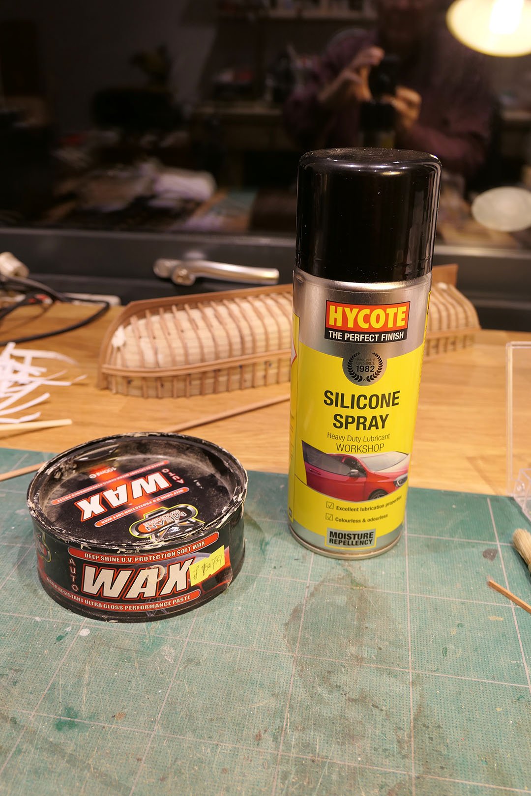
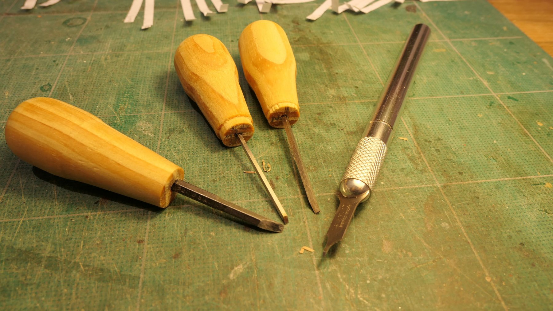
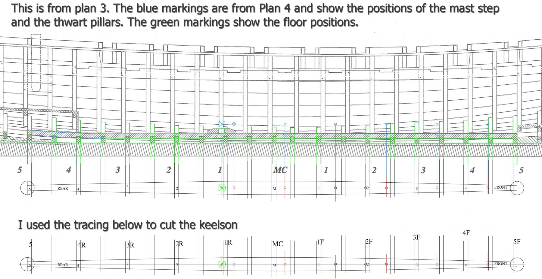
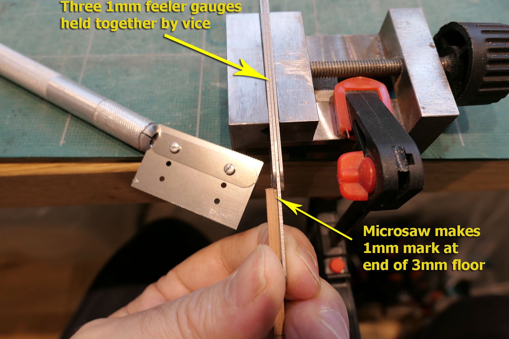
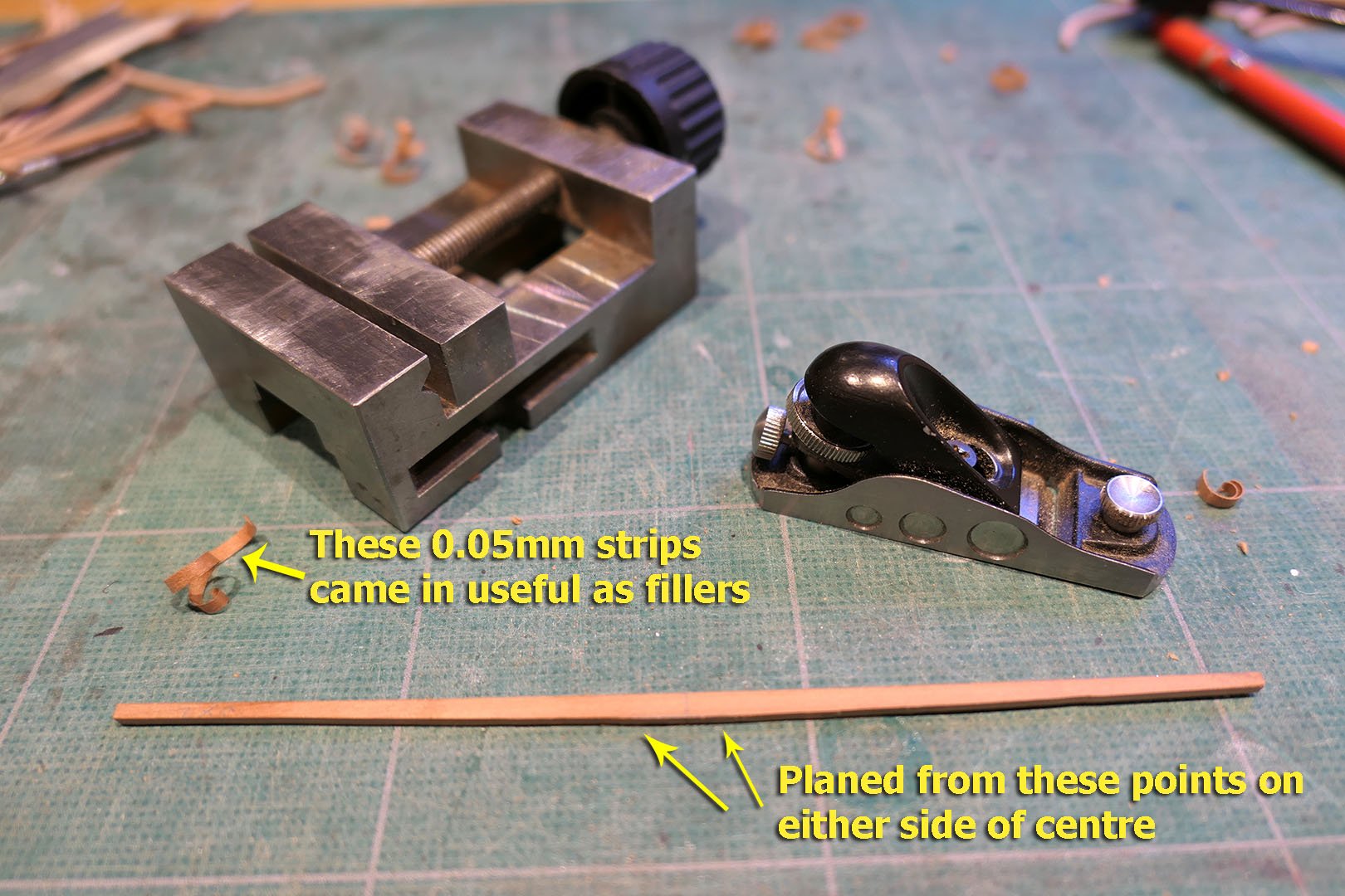
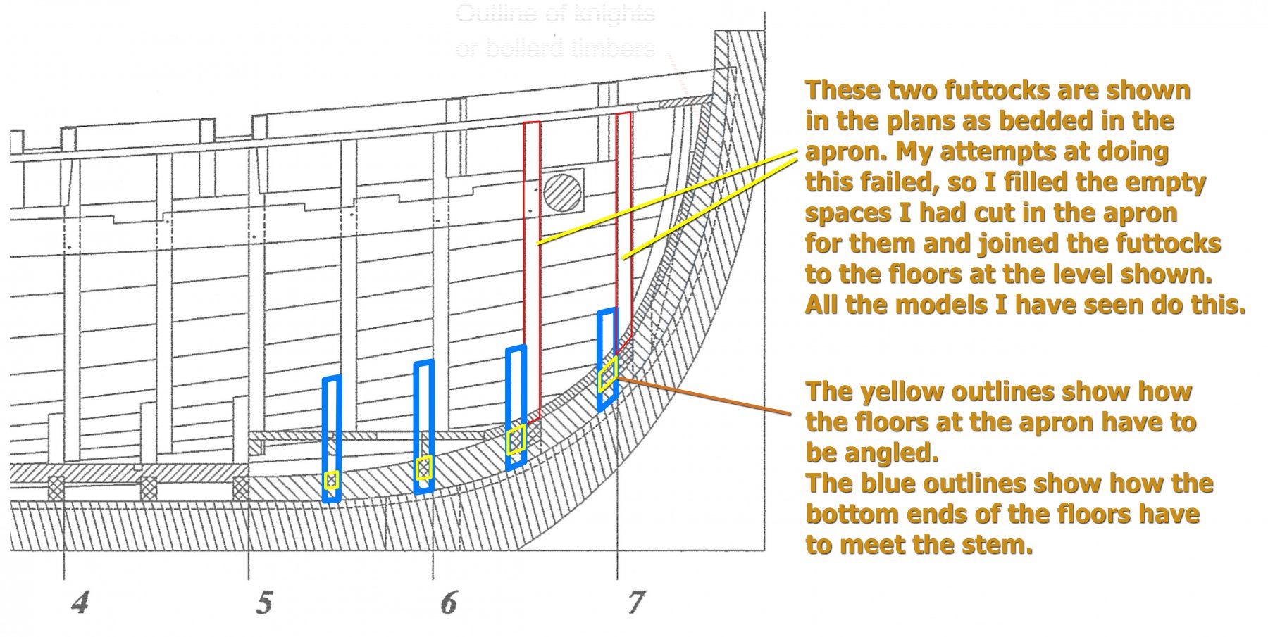
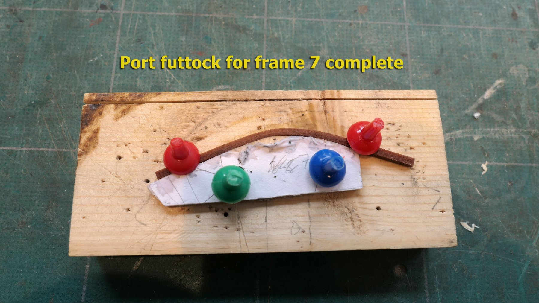
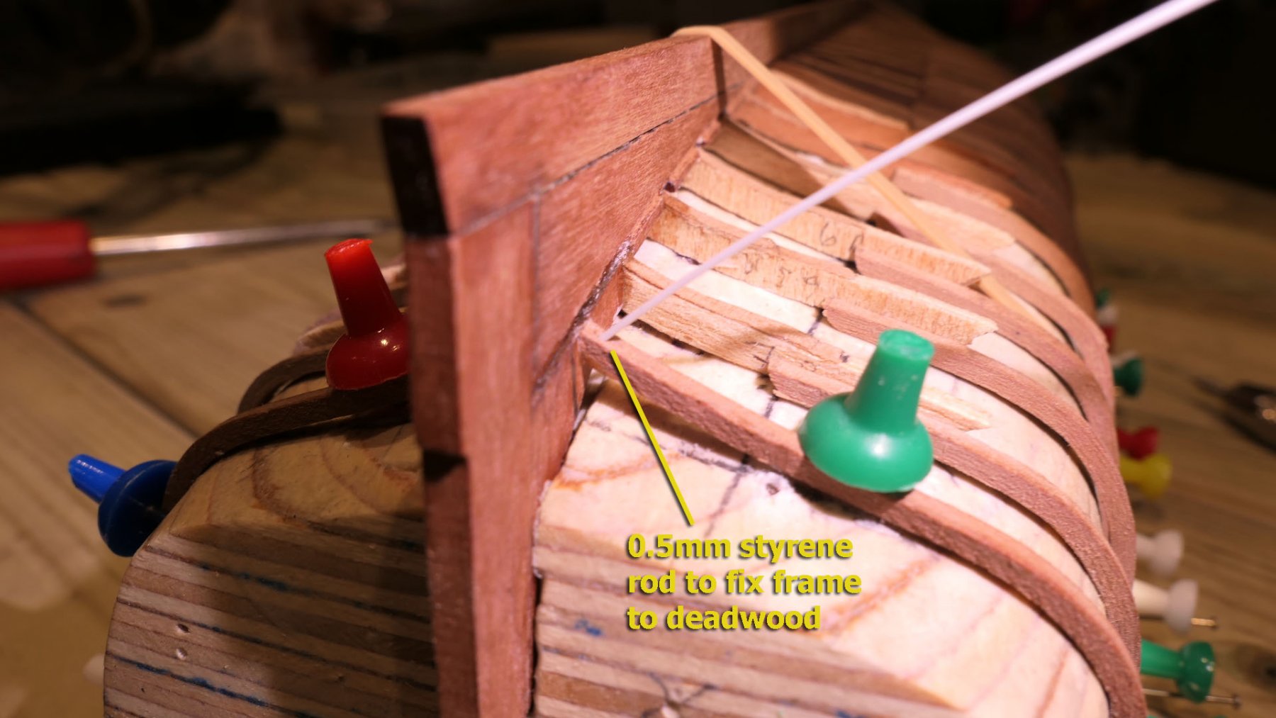
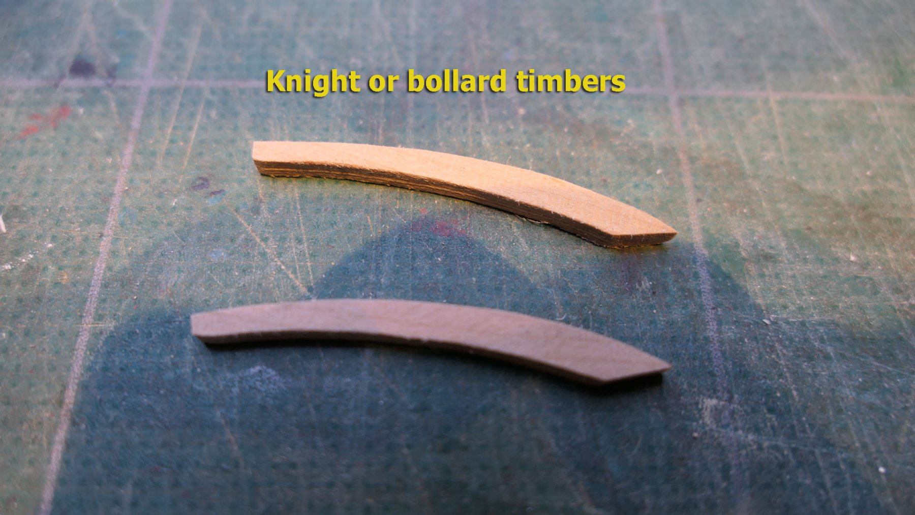
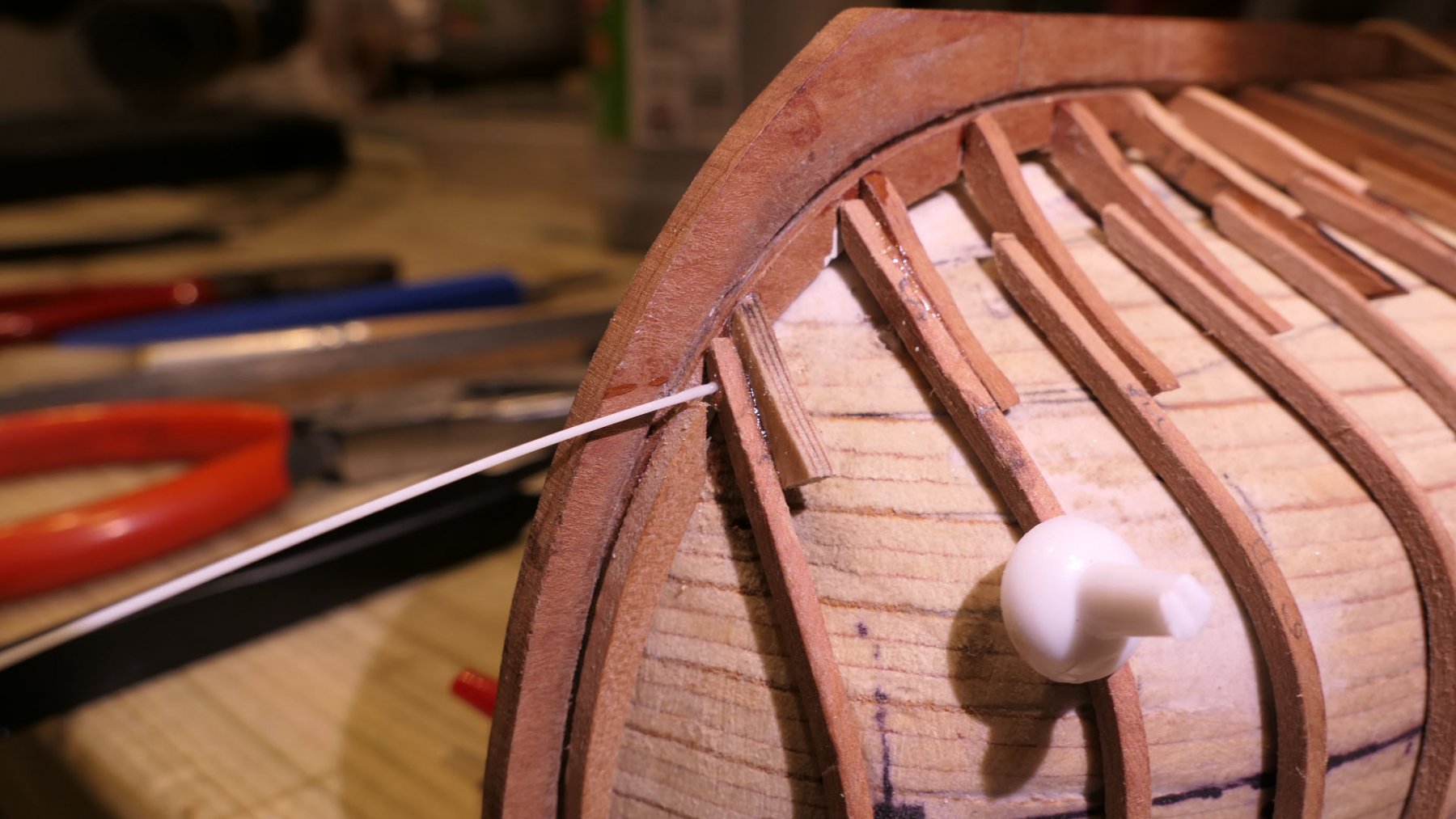
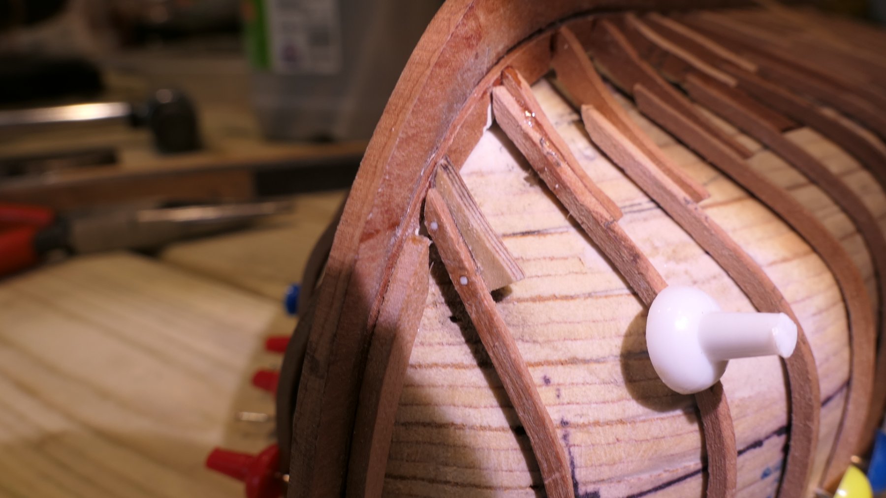
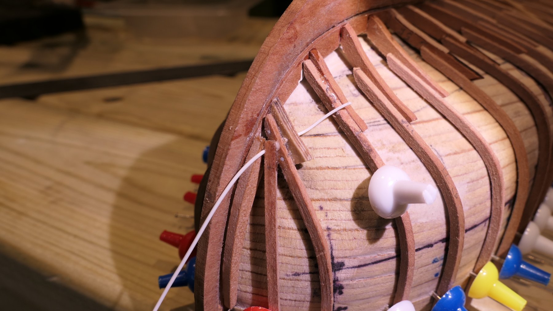
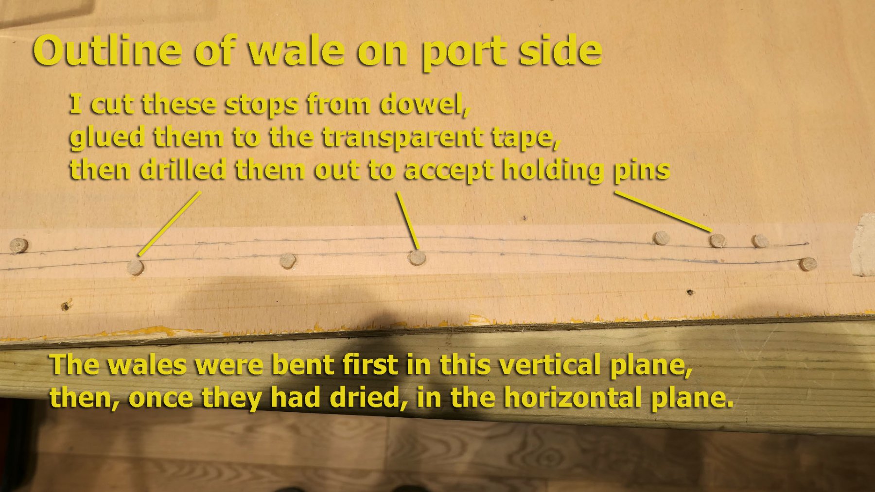
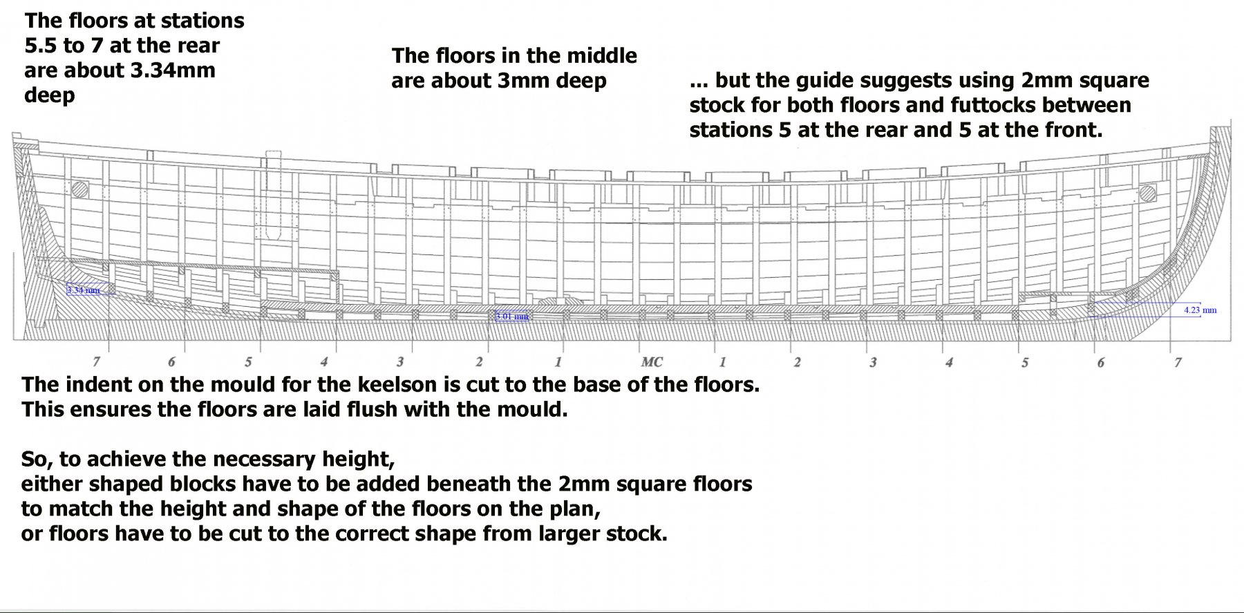
Great words everyone! Especially 'fun'. Michael: definitely for the builders sharing our early experience, but always looking for guidance from the more experienced! Thanks! And now on with the build to bring it up to date. Finishing the mould The final, but important aspect of finishing the mould was to cover it with wax or silicon to prevent frames being stuck to it when gluing floors and futtocks. I used the belt and braces approach by first spraying the whole mould with a silicon spray and then covering it with car wax. This gave me no problems when removing the shell from the mould. The only word of warning is that some modellers, having put a wax on the mould, found that, when they were heating frames to help bend them whilst on the mould, the wax would fix the frames to the mould. I didn’t experience that either as all my heating was done before putting on the frames and wales. However I did find that on several of the frames there was a residue of wax which was hard to remove except with a knife – so there may be a problem when I come to gluing the internal planks to the frames. In future I’ll just stick to the silicone spray. Calculating the amount of wood needed To calculate the amount of wood I made up a spreadsheet (based on measurement from the plans) which was sorted by plank thickness for clarity in ordering. You will note that I ordered 2x2mm sticks for the frames. This was because at the time I hadn’t given thought to the question of the floor size and assumed I’d be ok with the advice from the guide to use 2x2. I don’t yet know how accurate this spreadsheet will prove to be, but I can say immediately that I had also not thought about the question of spiling in relation to the planking which would mean thinking of strips 11 or 12mm wide. This is an issue (along with the issue of the floor size) that I will return to later in the log. Item thickness width length number total length gunwales 1 4.4 380 2 760 internal planks bow 1 4.6 54 16 864 transom planks 1 5 80 6 480 cubbies 1 5 20 8 160 cubbies 1 5 90 8 720 External planks 1 6 380 26 9880 Rear decking 1 6 75 11 825 floor planks 1 7 230 11 2530 washboards 1.5 3 350 2 700 internal stringers 1.5 4.6 320 2 640 planks behind swivels 1.5 5 30 4 120 taffrail 1.5 7 85 1 85 frames 2 2 250 30 7500 footrests 2 4 100 9 900 rubbing strakes 2 7 380 2 760 thwarts 2 7 100 9 900 transom 2 8.7 82 1 82 rear bench seats 2 10 50 4 200 cannon rails 3 7 180 2 360 rudder 3 7 70 1 70 rudder 3 7 40 1 40 bench rests 3 9 230 2 460 side knees 3 9 36 10 360 anchor davits 3 18 22 2 44 cannon rails 4 4 180 2 360 swivel supports 5 5 24 4 96 hoisting beams 5.35 5.35 85 2 170 I had chosen pear wood for the model, and some of this I had left over from the Triton cross-section build. The rest I ordered from Arkowood in Germany. It is difficult to get pre-cut sheets of pear of varying thicknesses in the UK because the good pear wood here is taken mostly for making veneer and the lengths of pear wood left are of variable quality. It certainly is convenient to have much of the wood pre-cut. Arkowood are able to supply strips of up to 100mm wide by 1000mm long with thicknesses that range from 0.5mm to 10mm. They also are cheaper in shipping (€16.50 to the UK) than the other big wood supplier (Massiv-Holz) which charges €26 minimum. Stem, Stern and Keel I did not take pictures of how I made the stem, stern and keel, but just need to remark that I made the lap joint between stem and keel by a straightforward milling out of the recess between both pieces and some very careful filing. I made the rabbet before adding the apron to the stem, although the guide suggested cutting the rabbet afterwards. This I did in three stages. I first used the mill to form most of the 1mm rabbet from where the rabbet joins the keel from the stern to the base of the stem. This is shown in the following picture, which also shows the further adaptations I made to my proxxon drill for use as a milling machine. You'll see all the mods in my Sherbourne build and other posts. I then cut the rabbet into the knee of the stern with a 1mm chisel I made from an ExActo chisel blade. You can see this and some other miniature chisels I made from an old hexagonal key (3mm) and some HSS lathe bits (2mm and 1.5mm). The handles are from an old broom handle, turned on a lathe. Finally, I made a scraper from a hacksaw blade to cut the rabbet that runs between the stem and the apron. I also used this scraper to tidy up the rabbet I had cut with the mill. If I was to do this again, I’d just do it with the scraper template. Keelson There is not much to remark about cutting the keelson. I had to remember: (1) the upward curve towards the stern, (2) to mark the positions of the mast step and the thwart supports. I used a combination of Plans 3 and 4 to establish the markings (I drilled 0.5mm holes right through so they can be seen from the top), and milled out the 0.8mm deep grooves for the floors. Frames I then started work on the floors. On the French forum there was much discussion about the fact that the plans indicate that the floors are 3mm in thickness whilst the booklet suggests making the floors and frames from 2mm square sticks. Most people seem to build the model with 2mm square sticks without much of a problem (or so it seems) but I couldn’t see how the frames would be faired with the last four frames and the first three frames which have to be made from plywood cuts derived from the original plans. For those such as myself who are anxious about this, the suggestion was to add filler blocks, but I decided it would be easier to make the floors from 2x3mm stock following the dimensions implicit in the Plans. The 2x3 stock clearly had to be shaped so that it narrows from 3mm at the middle to a 2mm thickness at the ends in order to merge with the 2mm futtocks. To mark the ends of the floors I used 1mm feeler gauges clamped together in a vice and a micro saw as follows. This method had an added advantage that I could use the 0.05mm strips planed off to make micro-adjustments to the height of the floors later on. Once this was done, I could bend them to shape using a jig. The next question was how to construct the first three and the last four floors. Because these would be difficult to make from 2mm strips, the guide suggests they be constructed from 2mm plywood sheet. M.Delacroix wisely suggests that 7-ply aircraft plywood be used. Since these would be invisible in the completed model, it will not matter in terms of appearance. In ignorance I bought 2mm ply thinking that was the same thing. It isn’t. It was 3-ply and crumbled quite a bit when I made the floors. The rear four floors were at least manageable in terms of providing a base for the planking. The first three floors were quite a different proposition. I tried making them from the ply I had bought and even from some pear stock, but all my efforts failed. The problem was cutting the first three floors to the rake of the stem on both inner and outer surfaces. This leaves a thin base to the floors which is very easily snapped. I eventually was able to buy 7-ply aircraft plywood, and this did the trick. You will see from two illustrations below some of the difficulties with the first two floors and futtocks. The plans show that the futtocks also cut into the apron, but although I cut out the grooves for them my attempts failed at cutting and bending into these grooves the 2mm square pieces for the futtocks. They all broke. In fact I have not seen any models that have done this, but I thought in the interests of learning I’d have a go. Instead I filled the spaces I had created for the futtocks with Milliput super-fine white epoxy putty (which is great as a filler, especially when it can’t be seen in the completed model) and ended the futtocks away from the apron – as is shown on the photos in the guide and on the other models I have seen. The other thing to note is that the guide suggests using a bevel to align the floors with the apron and the stem. I found that the only way of doing it was through a bit of trial and error, mostly error and breaking 3 floors to end up with one. I used a riffler file to align the uppermost surface with the apron. Another way to do this might be with a rounded bit on a rotary tool. To illustrate what I mean, the following shows frame 7F, the foremost frame, with the outline that covers both floor and futtocks. Ideally I would draw the frame from both its forward and rear sides (the plans don’t have any frame outlines as you have to devise them yourself), but the illustration should be sufficient to give you the idea. It took a lot of thinking on my own part to interpret the plans, so I hope that this explanation will shorten the thinking time for others who may find the same difficulties. The transom I positioned the 2mm ply base for the transom. It was cut deliberately oversize around the base to allow for adjustment when fairing the frames. This was done before adding the futtocks. I then glued the floors to the keelson, and the keel assembly to the floors. Then pinned the ply base for the transom to the mould. Bending the futtocks After reading Chuck’s posts on planking and his proposition that dry heat is sufficient, initially I tried just using dry heat for the frames with a hair dryer, bending the sticks over copper plumbing pipe and over a soldering iron. I found this impossible. No matter how slowly I bent the sticks, they all broke. So I went to heat with steam. I made three jigs. (1) for the frames between 7.5R and 5F, all of which were based on Frame 0; (2) for the frames from 5.5F and 6; (3) for the frames 6F to 7F. The one for Frame 0 is shown in the following photo: I then soaked lengths of 2x2 pear wood in boiling water for 20 minutes and bent them using a soldering iron along the sides and edges of the wood. I covered not just the immediate area to be bent, but also further along the wood on either side to ensure even distant wood fibres would stretch. I held the iron to the wood until steam could be heard sizzling from the wood. I then held the iron along the side in the same way, moving it back and forth until the sizzling started. I only moved the frame gently until resistance was felt, then I applied water again with a brush and repeated the whole process until the frame was the correct shape. I then moved the iron along its complete length until fully dry. Frame assembly I glued the keel assembly to the floors on the mould with epoxy and ensured it was vertical by pinning stern and stem with two pins. I then added futtocks 7.5R to the stern deadwood, and pinned them into place with 0.5mm styrene rod. Then I made the knights or bollard timbers and glued them to the sides of the apron, and then locked the foremost frame with styrene dowel as well. The extra intermediate front frame was then added and fixed with the styrene rod as well. I completed the assembly round the stem by filling all the spaces with the epoxy putty to ensure the strength of the area and a good base for the external planks. The following picture was taken after I had installed the wales. Wing Transom The wing transom was cut from 2mm stock and a rebate of 1mm milled to accommodate the top plank of the transom. I remembered to drill the holes for the future installation of the rings and the upper gudgeon for the rudder. You’ll see a white blob on the last frame in the picture above. Just as with the foremost timbers the joint at that position was not strong, despite the pin I had put in. So I surrounded it with epoxy putty just to make it really secure in readiness for the sanding. Wales You’ll already have seen the wales in the preceding photos. I cut these using from 7x3mm stock which I cut down to width with a table saw and the correct thickness with a Proxxon thicknesser. I then used a scraper made from a hacksaw blade to give them their shape before bending to the hull. I marked out the position of the wales on the frames, placed transparent tape over the marks, copied the marks to the tape, then transferred the tape to a plywood board. I made small stops for the holding pins in order to avoid marks on the wales as they were bent. I then bent the wales to shape very simply in two stages by spraying with water and heating with a hair dryer: (1) in the vertical direction; (2) in the horizontal direction after they had dried. Although there was some spring back in the vertical direction, when it came to gluing the wales to the futtocks they went into position without a fuss. As before, I used slow-acting epoxy (Araldite regular) for fitting the wales as this gave me all the time necessary. Finishing the rabbet I finished the rabbet by cutting it below the transom and bevelling it to align with the floor directions using a small burr on my drill. Taking the hull from the mould After sanding the exterior of the frames, I then took the hull off the mould and sanded the interior. I found I had over-sanded the last four floors on the port side, so used the epoxy putty to make them good. They won’t be seen in the finished model, so no great harm done. So this brings me up to date and future logs will be shorter. Next up will be the external planking, so it may be a while before the next post! Tony

.thumb.jpg.852c83a5f3bed6c7831d4b9c321c9eca.jpg)

.thumb.jpg.edaecb3e9f14946f62ab0bc8eef0c3ec.jpg)
.thumb.jpg.8f3630660716612ecbb16fd90be14b03.jpg)
.thumb.jpg.5f365cc0e7019a1e1b8989759d5dd319.jpg)
.thumb.jpg.dd13d965352707d8cb3efa179378224e.jpg)
.thumb.jpg.9ceded3b45bf6cbf2d745867836f5686.jpg)


- 124 replies
-
- 26
-
-
- longboat
- Chaloupe Armee En Guerre
- (and 1 more)
-
Glad that life now allows you to continue! Nice work! Tony
- 714 replies
-
- 2
-
-
- lady nelson
- victory models
- (and 1 more)
-
Thanks, Druxey, but self harsh? Not really. I see it as objective assessment and as a stimulus to further improvement. It's not false modesty either. I just want to be clear to others what my objectives are at my stage of the game -- the good things they might expect as well as what not to expect. When I look at my performance I give myself good marks for thinking, learning, explaining, risking and experimenting, but low marks for finishing to give the beauty that others achieve. I especially enjoy finding ways to fix the mistakes that I make -- even though the fixes are then quite visible. That doesn't mean I don't appreciate the work, just that it's in comparison. I know that as I continue I'll get better at the finishing. As with my response to Chris, I do appreciate all the encouragement and advice that you and others give so generously. I'm certainly going for it, as always!
- 124 replies
-
- 4
-
-
- longboat
- Chaloupe Armee En Guerre
- (and 1 more)
-
Ha ha, Chris! Just you wait to see! All the same, thanks for the hopeful encouragement! At the very least I do much enjoy the whole process, and that's the main thing. Tony
- 124 replies
-
- 5
-
-
- longboat
- Chaloupe Armee En Guerre
- (and 1 more)
-
Plank length for longboats
tkay11 replied to tkay11's topic in Building, Framing, Planking and plating a ships hull and deck
That's funny, Ron, because last night I had exactly the same thought! I think that's the way to go. I've just started my build log, by the way. Tony -
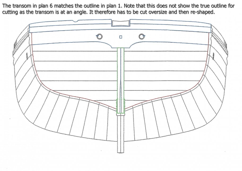
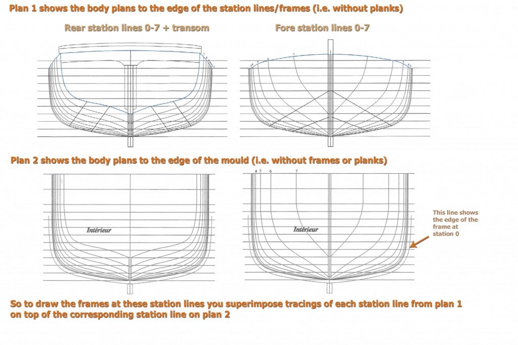
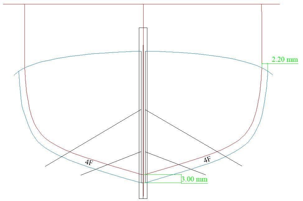
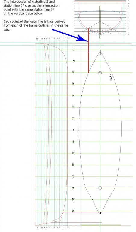
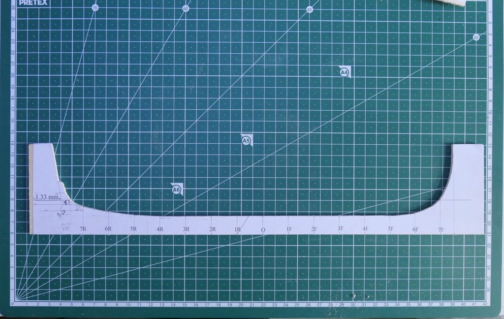
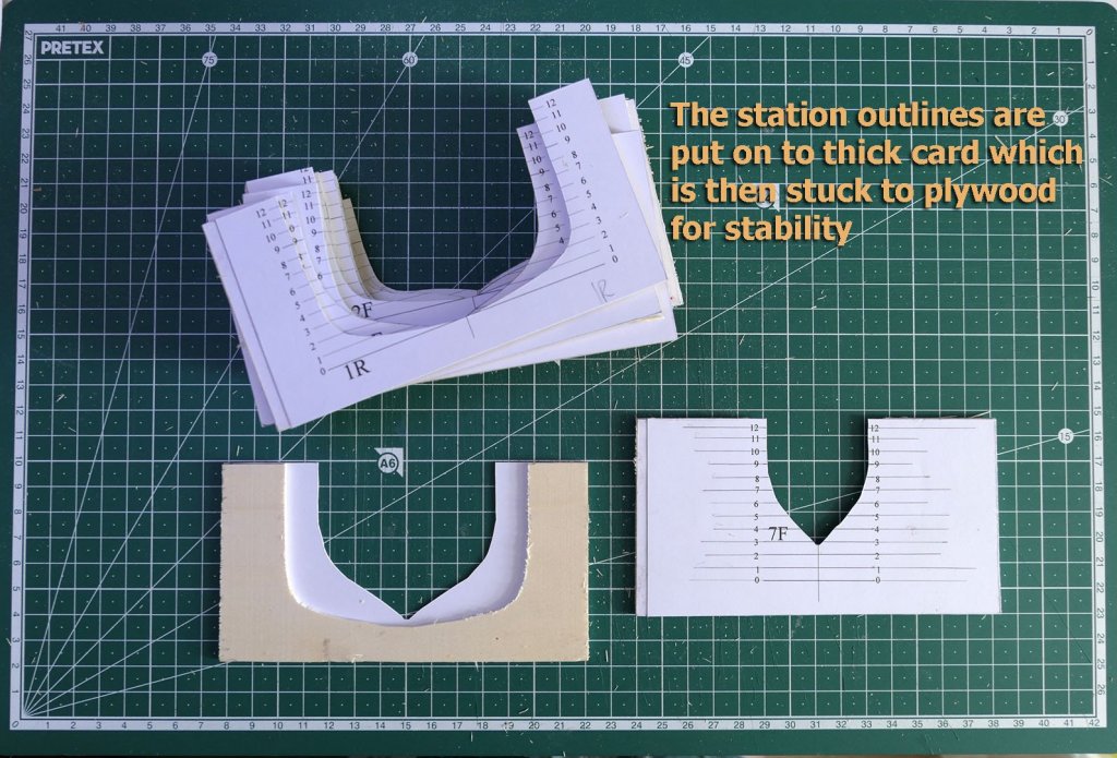
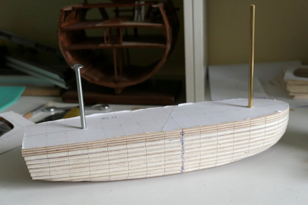
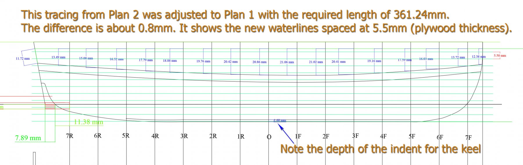
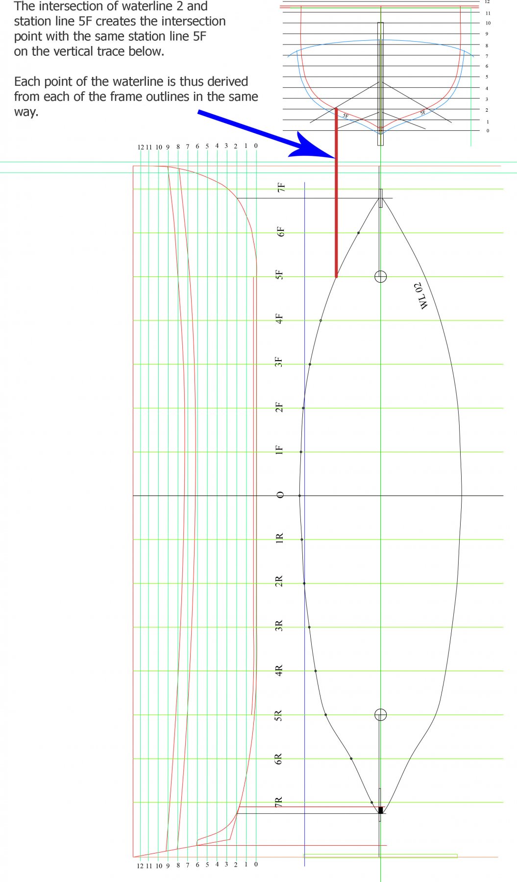
INTRODUCTION AND OTHER BUILDS In June 2017 I was considering what to build next. The main criterion was to keep learning but with a different type of boat and a different type of construction. I tinkered with the idea of La Jacinthe, Le Rochefort, and even thought of embarking on Ed Tosti’s plans for the Naiad. However I thought a logical next step would be to go for a longboat using a mould as construction type. So I started on Gérard Delacroix’ plans for the French armed longboat of 1834. The plans for this are available in several languages from Ancre at https://ancre.fr/en/monograph/31-monographie-de-la-chaloupe-armee-en-guerre-1834.html. As stated in the English translation of the introductory manual, the model is “based on a draught in the 1834 Atlas du Génie Maritime (Folio of the Corps of Naval Engineers). The longboat, at 42’8” long, is of imposing dimensions, being large even for a ship’s boat: a man standing on the bottom boards would have the thwarts at chest height.” This type of boat was used for the transport of the heavier loads required by warships and diverse tasks including carrying of anchors, shore duties, watering parties and carrying stores when the ship was in service. They could also participate in harbour defence and sometimes were armed with a single gun as well as several small cannon. There are several excellent builds that can be seen on the internet. The place to start, of course, is with the forum devoted to this model on Marine & Modélisme d’Arsenal at http://5500.forumactif.org/f83-la-chaloupe-armee-en-guerre-1834-plans-gerard-delacroix. There you can find a general discussion about points of interest that people come across while building the model as well as several builds. Very few of the builds go into the details of how they overcome problems as they come across them. However one in particular has gone to great lengths to detail each step of the construction. This is the build by Jean-Jacques Herault, which you can find starting with an index to the build at http://modelisme-arsenal.hlt34.fr/journal_de_la_chaloupe_armee_007.htm. All these builds are in French only. For builds in English, though, there are several on this forum: · Jeronimo’s build at https://modelshipworld.com/index.php?/topic/497-chaloupe-arm%C3%A9e-en-guerre-by-jeronimo-1834/#comment-5561. (Just pictures, no discussion of techniques). · Aykut Anşin’s at https://modelshipworld.com/index.php?/topic/5550-chaloupe-armee-by-aykut-an%C5%9Fin-small/#comment-159523. Only shown as far as the mould, last post in Feb 2015. · Decoyman’s (Rob) at https://modelshipworld.com/index.php?/topic/4218-chaloupe-armee-en-guerre-by-decoyman-from-the-delacroix-plans/#comment-120001. Fairly full discussion but last post was in July 2015, and only as far as frames made on the mould. · Smac’s gallery of the completed build at https://modelshipworld.com/index.php?/gallery/album/109-chaloupe-armee-en-guerre-1834/. · Blockplane’s (Chris) at https://modelshipworld.com/index.php?/topic/14743-1834-42ft-longboat-armed-for-war-by-blockplane-scale-136-first-time-wooden-boat-build/&. Complete, last post in May 2017. There is in addition a very useful series of 11 videos of a complete build (called Chalupa Armada) by Nacho Gomez starting at https://www.youtube.com/watch?v=HlUJabWYFTY. Each of these is over an hour long and is a useful reminder of how to use basic hand tools. All are spoken in Spanish, but even if you don’t speak Spanish the videos are almost self-explanatory. No doubt there are excellent builds as well in the Russian, Polish, East European and Japanese forums, but as I don’t speak any of those languages I simply have not researched them. If anyone does know of such other builds I’d be grateful to add them to the list. MY AIMS WITH THIS BUILD LOG Clearly, with so many builds of such high quality, you’re not going to get anything classy in this build log. It is a very basic build by a novice with poor finishing and lots of mistakes and ugliness. However, as with my previous builds, these are presented as they came, with the idea that there are lots of other builders with the same lack of expertise who come across similar problems and would like to see how I might have coped with them. I also know that along the way those who are more experienced might well chip in and give words of caution, advice and rebuke. All are welcome! FIRST STEPS As usual, the first steps are to study the plans and trace them into a CAD programme so that I can make accurate copies for cutting out and for planning. I use TurboCAD, which is very low cost and which I am now used to. The next thing is to make the mould. The plans are based on making a mould from 5mm thick plywood sheets (the waterlines are space at 4.5mm). Since that size is impossible to find in the UK, I had to work out how to make it from 5.5mm sheets. That meant making the waterlines spaced at 5.5mm, and so I set about doing just that using the time-honoured method of calculating the points of each waterline from the body plans of the station lines and the station lines set at right angles. In order to do so, however, although you only need the body plan from Plan 2 for the mould to create the water lines, I thought it would be a good idea to draw the frames completely as I’d have to be doing that anyway. The way to do this is to combine the body plans from Plan 1 (which shows the station lines to the edge of the frames but without planks) with those from Plan 2 (which shows just the body plan for the mould itself, without frames or planks). The result can be seen in the following diagram of one of the frames, Frame 4F (F for Front or 4Av in the plans, for 4 Avant). This shows that the frame starts at 3mm at the keel and taper upwards to 2.2mm at its tops – but this is an issue to which I will return later when I try to correlate the suggestions in the book to use 2mm square stock for the floors and futtocks against the 3mm floors derived from the Plan. For the moment all that matters is the trace of the inner aspect of the frame to create the mould. The following is the creation of the new waterlines to space at 5.5mm, which is the thickness of the plywood I was able to buy here in the UK. You will also note the various measurements I also inserted to help with the placing of the wales and the stern timbers. With the drawing of both the waterlines and the frames completed, I could then move on to drawing the outlines of each of the waterlines for the 5.5mm plywood. The method follows the classical way of doing this, so no surprises here. A final question that I faced for the creation of the mould was how to do that from Plan 2 because the stern shown in the drawing on that Plan has a very troubling empty space. At the time I decided to just follow the sweep of the hull, but it later dawned on me that a more exact way would be to superimpose the tracing of the outline from Plan 1 onto Plan 2. That way both the line of the hull and the cut for the sternpost and deadwood would be clarified. Should I ever have to rebuild the mould I’ll be doing it that way in future. The following diagram should explain it better. Now that all the drawings were ready, I set to cutting the waterlines from the plywood and, for the keel, cutting the 1.6mm groove for the keel using a 3mm milling bit on my Proxxon drill. I’ll be showing how I made the modifications for using the drill as a mill later on in this build log. I cut the outline for the sheer view with a scroll saw and a sander on my drill. The individual stations were printed to thick card and the cards then glued to a 2mm plywood frame for strength. And at last we get to the assembly of the waterlines. The above picture was taken on the 27th July 2017, just before sanding. After sanding it down I had to put aside all modelling as we were packing up the house to prepare it for sale and spending time searching for a smaller place to move into. I’ll therefore leave this log for the moment and the next part will take it from 29th September this year when I finally was able to start work on the model again. Tony

.thumb.jpg.79b3399afe366feb0b280de07fd5d8ac.jpg)

- 124 replies
-
- 15
-
-
- longboat
- Chaloupe Armee En Guerre
- (and 1 more)
-
Plank length for longboats
tkay11 replied to tkay11's topic in Building, Framing, Planking and plating a ships hull and deck
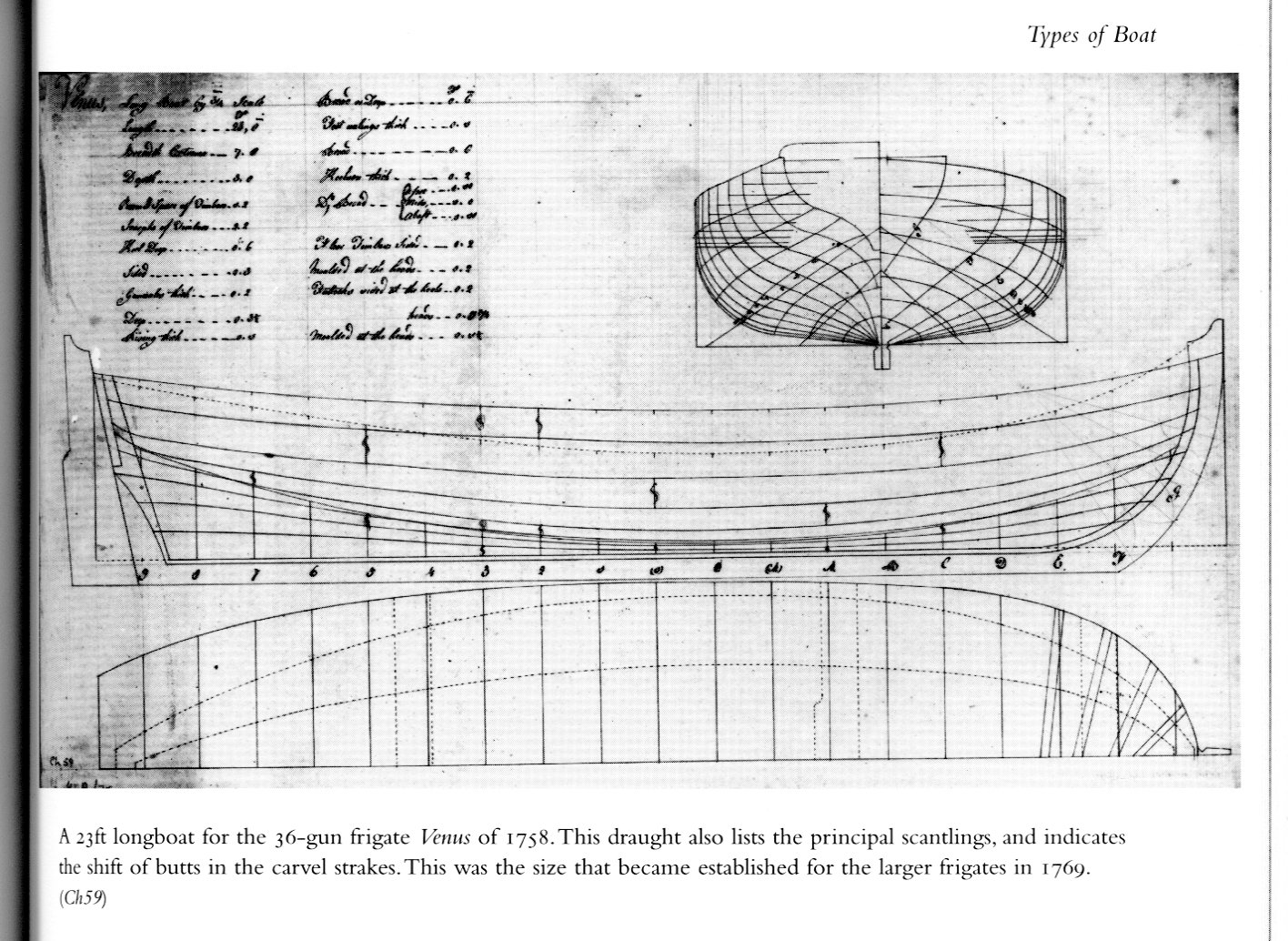
Thanks very much, Bob. A very logical analysis. Good point about the butt blocks. I attach the illustration from May's book which is for a 23' longboat of 1758 and shows the shift of butts. It states that this was the size that became established for larger frigates in 1769. Interestingly, even though it's only 23' long the planks shown are in the region of 12' long (according to my measurements of the scanned page, but also pretty obviously just from eye-balling). Tony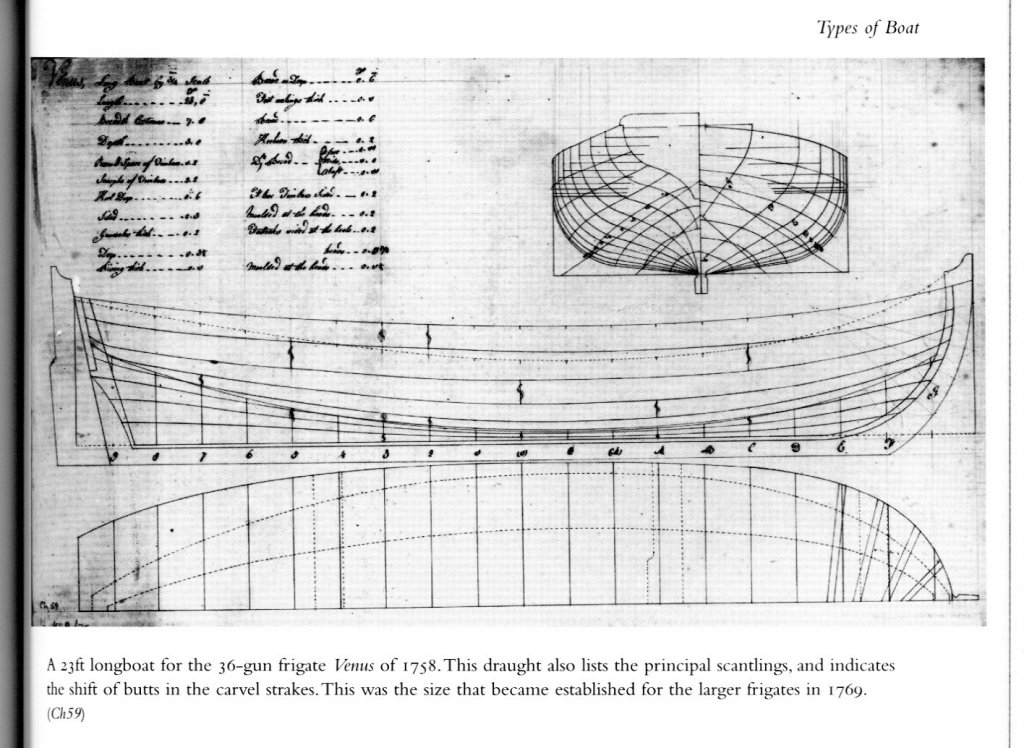
-
Plank length for longboats
tkay11 replied to tkay11's topic in Building, Framing, Planking and plating a ships hull and deck
Thanks, Mark. I have seen those builds. Rob's (Decoyman) was indeed helpful. From my point of view (i.e. related to my needs as a learner), the very best is the one by Jean-Jacques Herault at http://modelisme-arsenal.hlt34.fr/journal_de_la_chaloupe_armee_007.htm. I agree about the fact we're always learning, whatever the level, and that build logs allow constructive advice and criticism. Indeed my previous builds benefited enormously as a result. I'll gather up my thoughts and will probably go for it! Thanks for the push! Tony -
Plank length for longboats
tkay11 replied to tkay11's topic in Building, Framing, Planking and plating a ships hull and deck
I do have the rigging plan, which came with the book of Le Rochefort by M. Delacroix. I'll make my mind up about that once I get to near the end of the basic build. As to the build log, well, I can see the interest, but if I do it'll be more about how to struggle through and all the choices that are made. It certainly won't be perfection! Tony -
Plank length for longboats
tkay11 replied to tkay11's topic in Building, Framing, Planking and plating a ships hull and deck
Fincham: That's very interesting. I certainly had not expected that such lengths would be used. Thanks. Chuck: Thanks very much for pointing that out. I had missed it as I just went straight for the scantlings and didn't take the draft into my consciousness. I'm having second thoughts about breaking the planking into lengths as it would mean I have to put the butt ends on 2mm frames. I'll continue to think about it though. As for a build log, I've been hesitant. If I do one it'll be more for how a novice gets to grip with the trickier elements (much as I've done in my previous build logs). There are already some excellent build logs on the web for the Chaloupe, although only one goes into the details of the construction (and that's only in French). However there are enough puzzles to make a log interesting -- a notable one being the use of 2mm frames when the plans show something more complex. I have reached the stage of putting the wales on the frames and am about to start planking (hence my interest in the lengths). Thanks for the encouragement, though, Chuck! Tony -
I am working on the Chaloupe Armée (plans and booklet from M. Delacroix) and wonder what the standard plank length would be for the outer hull planks of this 42'8" longboat of 1834. The model builds that I have seen just place planks that are the full length of the boat, but at full scale I would have thought that 42ft would be too long. As far as I know, the normal plank length for larger ships would be 20-24', but would welcome any thoughts on how French longboats of that period would have been planked. I have the book 'The Boats of Men of War' by W.E.May, but the scantlings given in that book don't seem to give plank lengths. I have also looked at Chuck's Medway Longboat build and there he does provide two planks for several strakes together with a butt shift which suggests to me that this might be normal practice. As usual, I apologise if this question has already been dealt with but I couldn't find it in the forums so far. Thanks Tony


.jpg.3a99fb7f1e53531771f81a51168e1a93.jpg)

.jpg.118e8a3e7d20dc4a9eeb7a248a1ab08a.jpg)


.jpg.f3690b4a25a8d56d2b121bb1111a7919.jpg)
.jpg.3ac9a1d86409096a605922d7c30de60c.jpg)
.jpg.b87f0a50bbd782ae548b943bed45021c.jpg)
.jpg.6c353e7974af69d7aee6b3031e1d600a.jpg)


.jpg.a2b9b2e09b5ce45fcc2779b397dfe457.jpg)