HOLIDAY DONATION DRIVE - SUPPORT MSW - DO YOUR PART TO KEEP THIS GREAT FORUM GOING! (83 donations so far out of 49,000 members - C'mon guys!)
×


tkay11
-
Posts
1,829 -
Joined
-
Last visited
Content Type
Profiles
Forums
Gallery
Events
Everything posted by tkay11
-
 Doris uses the term 'foil' and her suppliers are at https://www.tapety-folie.cz/drevo/c-2404/. These look like pva or some kind of glue-backed pliant plastic. She stretches and shapes it with heat. Tony
 -
We had a discussion about this in August 2016 in relation to stowing the anchor on the Sherbourne. In the end I followed the diagrams from Harland's Seamanship in the Age of Sail. The general discussion was at I showed this on the model at I hope this helps. Tony
- 714 replies
-
- 3
-

-
- lady nelson
- victory models
- (and 1 more)
-
Great idea. Wish I'd thought of it! Tony
-
Model Ship Building Stands And Vices
tkay11 replied to LEGION 12's topic in Modeling tools and Workshop Equipment
I have a pair of these very handy vices which are the ones I turn to mostly. They do have a couple of downsides, such as strength of grip which seems to decrease with age, but in such instances I turn to the other types. These are readily available from parents, although it's good to be cautious when looking for a source online. Tony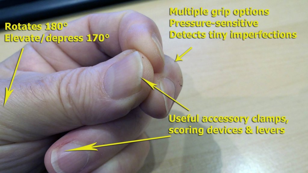
- 16 replies
-
- 14
-
-

-
I'm pretty much an amateur at this, but in case it helps I thought that Peterssen had added a simple loading tackle to the backstays based on the model he saw in the Science Museum even though it was not often seen in other contemporary models. You can see this in my Sherbourne log near the very bottom of the posting at In relation to the fiddle blocks on the yard, I am not clear about your puzzle, but if it relates to the yard ties I had some discussion about this at I think that Peterssen sometimes just gave a quick outline (as he did for the Burton pendants on a cutter) rather than filling in all the lines just so that you can see the main functionality of a section of rigging. You can also see the full discussion of the Burton pendant problem at I personally found Peterssen's book very good from the point of view of explaining rigging. For the details you really need to go to Marquardt and Steel as well as others already mentioned. I hope that helps Tony
-
Model Ship Building Stands And Vices
tkay11 replied to LEGION 12's topic in Modeling tools and Workshop Equipment
Once in Barbados I thought I'd go to buy a present of rum for a relative. I went to a local small supermarket and looked at the vast array of different types of rum. Not knowing anything about rum, I decided to ask the rather bored-looking young woman at the till for a recommendation. 'Suit yourself', she said, 'They all make you drunk'. Something similar may go for the various types of clamp. Perhaps they all hold your ship. Tony -
Understanding scales
tkay11 replied to kier's topic in Building, Framing, Planking and plating a ships hull and deck
You are not really clear as to what you do not understand about 'the theory of scales', so I apologise if you already understand that 1:65 means that on a model 1inch would represent 65inches on the real ship. If you hadn't understood this, to estimate the lengths that you need to use, all you have to do is divide the length you expect on the full size ship by 65, as the scale stated for the Artesiana Latina model is 1:65. So a 20ft length would work out at 20x12=240inches, which divided by 65 would give you 3.69 inches, or 93.8mm. I don't know anything about plank lengths on ships of that period in Spain but there are plenty of build logs on this site for your particular kit which may help, as well as for other kits of the same ship. As far as I understand, hull planking tended to be in the 20-24ft range, although that may be different on Spanish ships of the period. I don't think the length of the ship would have much to do with the length of planks used. This would be more dependent on the lengths of cut available which would be set against the need to have as much stability and waterproofing as possible. The widths of the planking would, of course differ depending on their position on the hull, between 1.5 times the width at the centre (which I think might have been 10-12inches), and 0.5 times that width. For the deck planking, zu Mondfeld in his book 'Historic Ship Models' says that before the 16th Century the width of deck planks was 12-18 inches, the thickness of the top planking 3 inches, the gap for caulking about 3/8th of an inch (and here I think he's referring to English inches). The treenail pattern would vary according to the width of the deck planks. I believe the length of deck planking would vary between 12ft and 20ft, but could well be wrong. More than the particular lengths of plank used it will be important to ensure that you have the pattern of butt shifts correct on both deck and hull. I can see that you've built a few models before, so you may well have read the excellent planking tutorials in the download section of this site, but I do recommend them in case you haven't. I hope this helps, but I would emphasise I'm certainly no expert. Tony -
I've just had a look at Scott's (bigpav) build of the Renown on this site from 2013. Like others he claimed the wood was terrible quality. I also note that it has a slightly unusual construction in that the hull is built in 2 halves on bulkheads and that he found difficulty when assembling the planked two halves. It may be done this way because of the way the propeller shaft is fitted I downloaded the plans and instructions from the Billings site and suspect that the biggest problem might be in building the hull and that the remaining fittings would be relatively easy, especially given the lack of masting and rigging. Given that the plans are provided there is always the possibility that if you make mistakes you can build your own hull using the drawings. Given his difficulty with the halves, you might find it easier to fit all the bulkheads of both sides and glue them together before planking. It might give you more leeway to ensure the symmetry of the hull. You'll find a reasonable build log by Charles on Model Ship Builder, where he did plank after the two halves were fitted. As others have said, this is an interesting ship as there are so few builds on this site, and there'll be plenty of people to help you when you ask questions. I won't say good luck with the build as it's not really a matter of luck -- more with patience and perseverance as you meet difficulties and try to overcome them. So I'll say I hope the difficulties prove to be few and the rewards many. The painting should prove great fun. Tony
-
It used to be done via a link inserted with the title of the topic on its first page. That link was removed with one of the software upgrades, so I suspect the moderators made a policy decision about this. I seem to remember complaints about people 'stealing' work and labelling it as their own on other model sites. Tony
-
Thanks for the encouragement, Jörgen. I'll read up about it once I finish my current build. I think there's plenty of advice on the web but I note that there is nothing in the articles database in the area labelled 'painting'. I am pretty sure that if you write an article about your own methods and place it there it would be of interest to many on this forum who might like to try it. Tony
-
Yes, that join at the stern counter is certainly very challenging. A good solution. I also appreciate the use of an airbrush. I don't know how to use one but I can see they produce great results. Tony
-
Thanks a lot, Wefalck. I had not thought of it before, but the derivation of 'pierrier' might more simply be from 'pierre' (i.e. 'stone' in English). I am ashamed to say that I had not thought of that obvious link but your thought gave the clue. It is clear that 'pierriers à boîte' (i.e. 'stone throwers with a box') refers definitively to the breech-loading swivel guns whilst 'pierrier' may well be the generic one for swivel guns. The Wikipedia articles are therefore misleading in using the term 'pierrier' as referring only to those 'à boîte'.
- 9 replies
-
- 2
-
-
- swivel guns
- cannon
- (and 1 more)
-
Thanks very much, druxey, dave and wefalck. Sorry for the delayed reply but I've been having surgery and am only just out. All of you I know are far more knowledgeable than I am both in modelling and historical understanding, but I thought I'd let you know why I asked the question just in case there's a bit more to be said about it. It all hinges on the definition or the practical usage of the word 'pierrier'. All the french modellers who have posted logs have used the term 'pierrier' to refer to the swivel gun on this boat. All of the builds I have seen show muzzle-loading swivel guns. I looked the word 'pierrier' up just out of interest and both English and French Wikipedias seem to suggest that the word 'pierrier' specifically refers to the a breech-loading swivel gun, and in addition suggested that this type of gun was used until the 19th Century. I have no idea whether the French use 'pierrier' for both muzzle-loading and breech-loading swivel guns so perhaps someone could enlighten me on the French usage of this word. I personally haven't done any more detailed research on this yet, for example in discussions of French naval artillery. Perhaps I can do that during my recovery period while I have to avoid modelling. The following is from the French site at https://fr.wikipedia.org/wiki/Pierrier : "Un pierrier est un canon, utilisé jusqu'au XIXe siècle notamment sur les navires ou les canonnières, et qui lançait des boulets de pierre. Il pouvait également lancer des boulets de fers ou de la ferraille1. Un pierrier se charge par la culasse, au moyen de cartouches2 ou boîtes." In translation this is: "A 'pierrier' is a canon, used until the 19th century mostly on ships or gunboats, which shot stone balls. It could equally shoot iron balls or shot. A 'pierrier' was loaded through the breech using cartridges or boxes." Looking at drawings of breech-loading swivel guns I could see that there was a steady evolution of styles from the 15th century onwards and just picked one at random to indicate the style. So I understand your answers about the breech-loading types may well be correct in that they were outdated by 1834. The suggestion that they were used 'until the 19th century' would be consistent with that if it means 'until 1800'. The interest may therefore focus more on the word 'pierrier'. Thanks for any further enlightenment! Tony
- 9 replies
-
- 2
-
-
- swivel guns
- cannon
- (and 1 more)
-
I think that something new and complex like that, with a focus on learning, is a really good strategy. It does allow you to circulate the thoughts about your problems somewhere in the back of your mind until you come to terms with a new reality or suddenly discover ways out. Setting aside your model for the moment is a little like putting your past behind you for a while as you process everything. It's just sometimes hard to have the discipline to do this when everything else seems so overwhelming, but it does look as though you have that discipline. You put a huge amount of energy into this forum, and care in looking at and commenting on the efforts of so many of us. We all appreciate this enormously. As have done the others, I do wish you well and hope that life rearranges itself the better for you whilst you rearrange your self. Tony
-
Yes, glad to see you back on the forum. Looking forward to the rest of your build. Tony
- 161 replies
-
- 3
-
-
- pegasus
- victory models
- (and 1 more)
-
Ah, Gérard, that explains it perfectly. I feel a bit of a fool for not thinking of that as it now seems so obvious. Thank you so much! This will allow me to continue with a bit more confidence. And thanks for taking a look at my log! I really hope other modellers will take it up as it's such a nice model. Tony
- 124 replies
-
- 2
-
-
- longboat
- Chaloupe Armee En Guerre
- (and 1 more)
-
Thanks, Dirk and druxey. Good advice. I agree about the pressure, and have been wondering about the effect of the grain. I'll be much more careful on the rear cabinets and always bear in mind the need not to rush. I might even re-do the knees if I have enough wood as the look when it's done nicely really does make a difference. Tony
- 124 replies
-
- 3
-
-
- longboat
- Chaloupe Armee En Guerre
- (and 1 more)
-
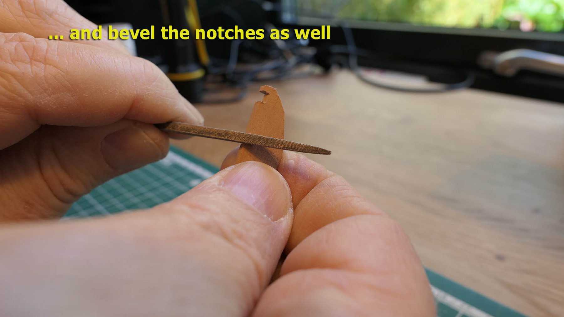
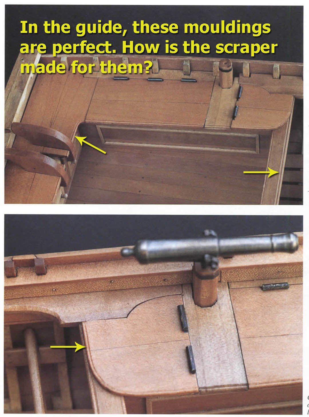
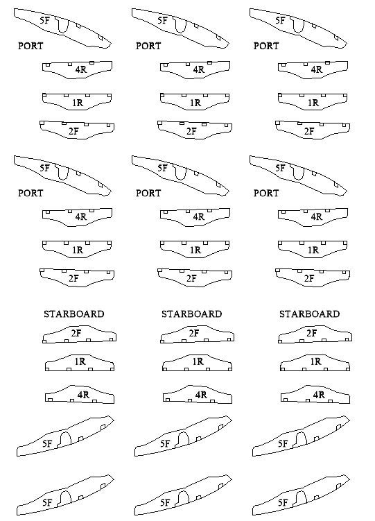
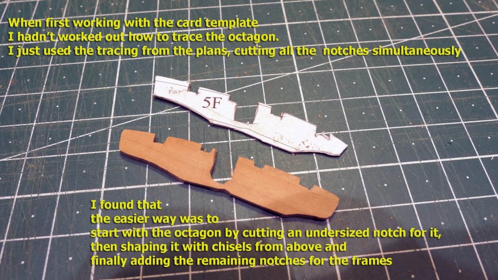
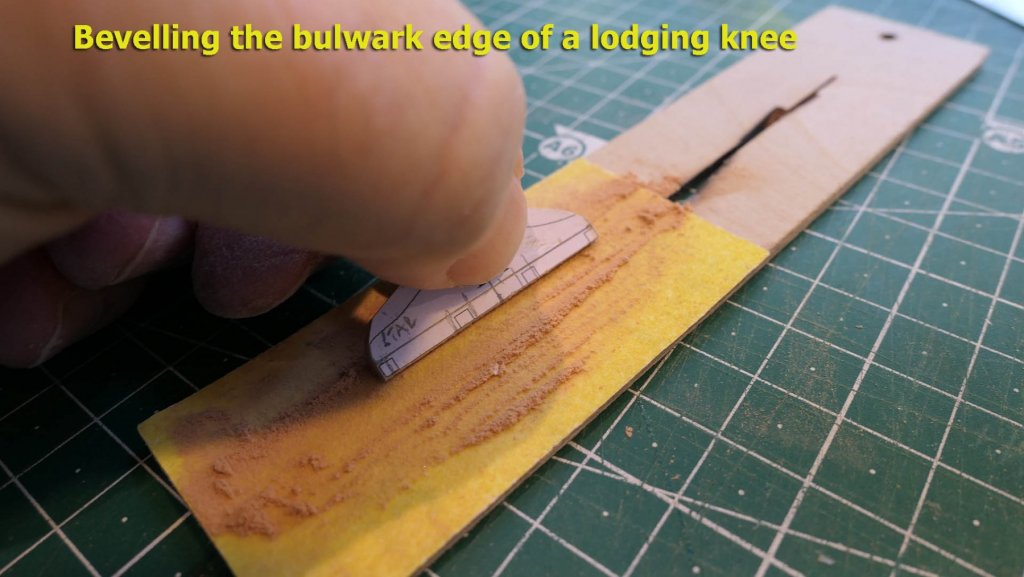
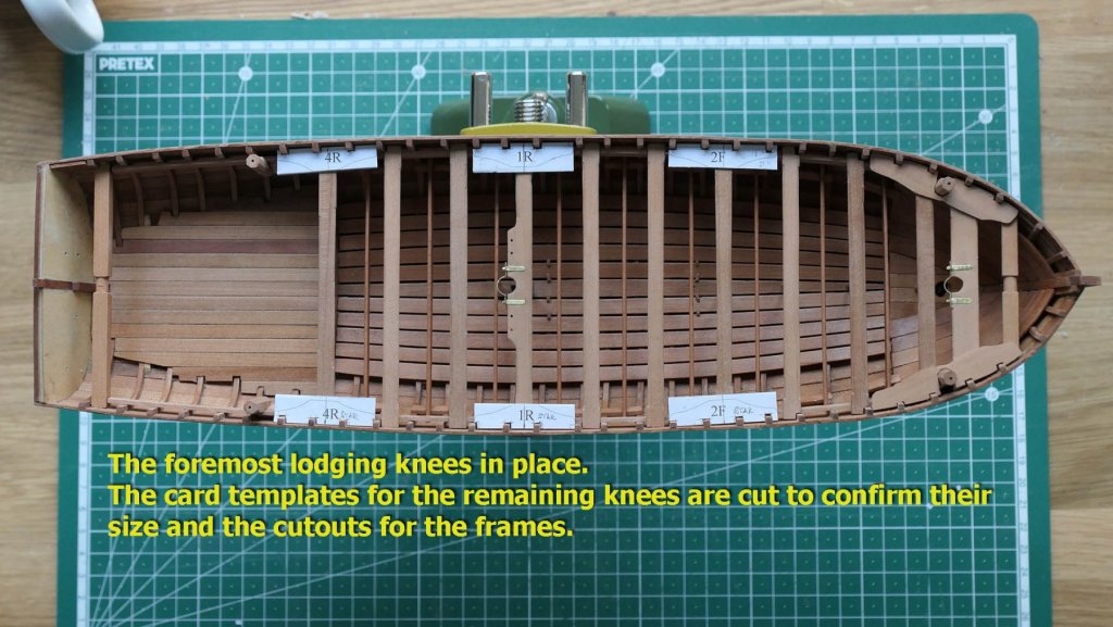
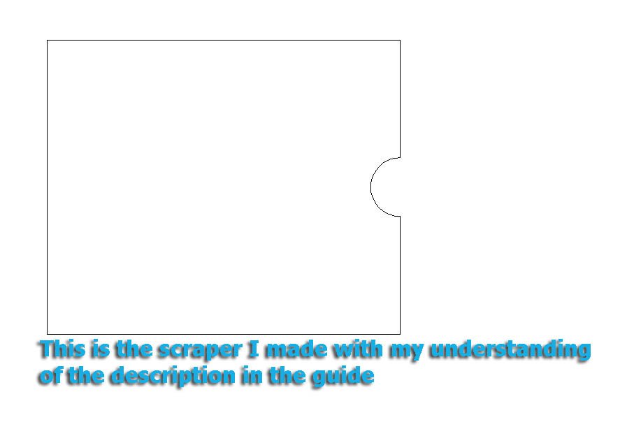
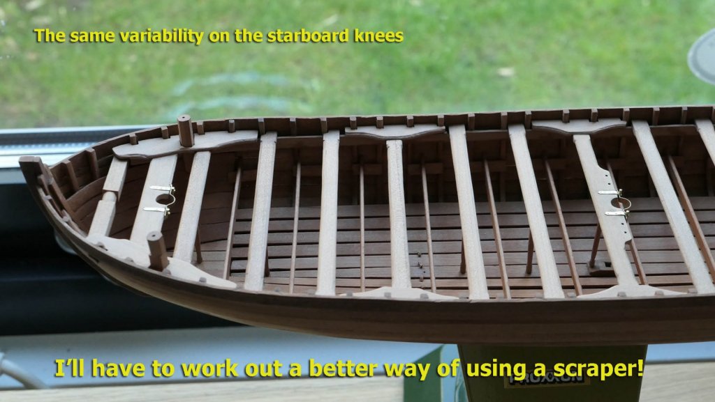
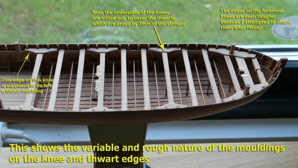
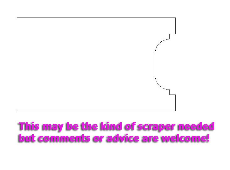
Thwart lodging knees Thanks again for all the kind comments and likes. I’ve managed to squeeze in one last log before my enforced absence. As usual, I predict in advance that I’ll have difficulties by preparing several copies of the tracings I need: in this case of the thwart lodging knees. I use these templates to fix first to card, and then, once it all seems ok in terms of fitting, would use them for the final wood knees. I really used them up this time! In order to take account of the possible variation from the plans in the shape of the bulwarks and frame positions, I cut out the templates leaving plenty of extra space on the bulkhead sides. I knew I’d have a bit more trouble with the foremost lodging knees because of shaping round the octagon of the swivel gun stocks. At first I just used the card template and cut out all the notches for the stock and frames at the same time. But the cut for the octagon just turned into a mess as I tried to fit the card to the bulwarks. Second time around I realised that the primary cut would have to be for the octagon as this would determine the position for the remaining cuts. So I cut out an undersized notch for the octagon and, from a position above the bulwark, gradually shaped it to fit using a small chisel. Having got that right, I then shaped the outline to fit the bulwark while keeping the orientation of the octagon, and and only then marked the cutouts for the frames. Accurate placement of the knees also required bevelling the sides against the bulwarks – including the sides of the notches. Finally, because the thwarts sit proud of the stringer by 1mm, it is important to mill out a 1mm cut in the bottom of the knees so that they fit flat over the thwarts. It was only after fitting the fore lodging knees that I remembered that their edges had to be moulded. Earlier in the guide, when talking of the moulded timber along the axis of the apron, it says ‘The moulding is nothing more complex than a quarter-round worked on each side. A miniature moulding plane should be made up for the purpose, with a circular hole at the edge of the blade of the same diameter as the cutting disc. Put it aside when you have finished, because we will need it again for several other timbers’. I wasn’t sure how to interpret this, so I made the moulding plane with the following shape: It then said with respect to the thwarts that ‘the upper edges are worked to a quarter-round’. I assumed that the same scraper would be used but, as you will have seen in the photos of the thwarts, the outcome was quite patchy. All the same I persevered, and when it came to the mouldings for the lodging knees I again used the same scraper hoping that by now my technique would have improved. The following picture shows how the mouldings SHOULD have turned out (the photos are from the guide): I tried holding the scraper at right angles and then at a diagonal to the knee, but unfortunately the roughness and variability turned out much the same. So I assume both my scraper template and technique are wrong. I’ll experiment a bit before I go on to the cabinets at the rear. That will be when I’m out of hospital. In the meantime my first proposal for a template is as follows. I think that one of the problems was that although the shape was roughly correct, there was no way of centring it to the thwart or knees. Any comments or advice are welcome in the interim! Thanks again Tony


- 124 replies
-
- 10
-
-
- longboat
- Chaloupe Armee En Guerre
- (and 1 more)
-
Thanks, Michael. I agree about the trig. I liked Dirk's comment about 'tutorial style', as it is just a style and not quite a tutorial (if that is taken as anything definitive). The style is to explain in detail the steps I personally took to approach each stage of the build which other novice builders like myself may also find puzzling. I remember your earlier comment that you "took a close look at each drawing and the manual. It seemed to be too tricky for a beginner like me". It's exactly because there are a lot of people who feel the same that I try to show that if you break the task down to individual components or steps, then it may not be as difficult as it first looks. There's a nice saying in Chichewa which says "the wingless grasshopper covered the whole country just by hopping" (it's a bit more poetic in Chichewa!). Before kits came to the mass market, building boats from plans and guides was quite the norm for beginners. It's true that kits are a good entry point for getting your eye in (I started with the Sherbourne kit) and lots of people then find that they start modifying the parts that came with the kit (which gives them the confidence to building from plans and guides), but it's not necessary. There are many ways, materials and tools one can use when approaching each stage of building a model, and I just illustrate my own methods. People with more experience may well see more efficient ways of doing these things. I base my own approach on seeing how others have tackled the various similar types of difficulty by following the logs on this forum, reading lots of articles and books, and gradually understanding the 'language' of model building that they evince. However, learning by doing, by making mistakes, and by playing with pieces in your hands provides another equally important role in learning and thinking how to do things using the tools and materials at hand and your preferred methods of working things out. This is all by way of saying I hope I don't come across as being definitive, more to stimulate people to look at problems for themselves, have a look at what others (like myself) have done, and then think about whether those particular approaches suit you or whether you can see a better way through for yourself. That way your own experiences will become learning points for others as well as for yourself. Writing a build log is an excellent way of learning, as I continue to find. Don't forget: it was you who stimulated me into putting in those hoisting beam extensions. Without that stimulus I wouldn't have learned how to do it! Tony
- 124 replies
-
- 3
-
-
- longboat
- Chaloupe Armee En Guerre
- (and 1 more)
-
Thanks for the good wishes, as well as the compliments. Both are much appreciated. When I told my wife of druxey's comment about showing the surgeons the pictures to promote accuracy, she said "Be careful with the comparison. Unlike modellers they can't re-do the bits that go wrong". We're a down to earth family. Tony
- 124 replies
-
- 4
-
-
- longboat
- Chaloupe Armee En Guerre
- (and 1 more)
-
CAD help needed
tkay11 replied to Cabbie's topic in CAD and 3D Modelling/Drafting Plans with Software
I forgot to mention DesignCAD which is produced by the same company that makes TurboCAD but it's easier to use than TurboCAD, albeit still with a need to learn how to use it with the help of online tutorials. It's also cheaper. You can compare them at https://www.turbocad.com/blog/turbocad-vs-designcad-n9. Tony -
CAD help needed
tkay11 replied to Cabbie's topic in CAD and 3D Modelling/Drafting Plans with Software
I think it's up to you to decide which programme to use based on trying them out. Different people on this forum have different ideas about which programme suits them best. It's a bit like the preference between Apple Macintosh computers and those from the DOS/Windows worlds. Different minds and different learning experiences lead to different preferred ways of using tools. From my personal view and experience, the simplest programme I have found is SketchUp which is free. This gives very clear dimensions to line drawings. There's an old version of TurboCAD v12 which was free and I found very simple to learn in conjunction with the numerous tutorials and help on the web. The latest version of TurboCAD, though, is quite expensive (around £100). You can pick up used copies quite easily on eBay. If you want to have the free version of TurboCAD, you're welcome to have mine as I don't use it any more. The programme I use regularly is TurboCAD DeLuxe v21 which I bought for about £24 a couple of years ago as I was lured into the upgrade path with more 3D capabilities. There seem to be quite a few free CAD programmes available on the web. I have tried Blender and Draftsight in addition to SketchUp but each requires practice and learning its own way of doing things. Good luck with your search! Tony -
Very nice progress, Jörgen. Those treenails have come out just fine, and the lids are wonderfully precise. Are you going to give the lids hinges or some other means of holding them? I also appreciate your modifications and re-thinking. I really agree about the benefit of wood modelling. Kits give a great feel for working with the ideas and tools and are the ideal way of starting, but it gets even better when you start building just from plans as the number of degrees of freedom increase dramatically. I also very much appreciate the added photos of the planes. There the challenge is the seamless finish combined with great care and skill in paintwork: both of which you have accomplished admirably. They remind me of my younger days with Airfix kits of World War 2 fighters and bombers, although I never achieved the level of execution that you have. Tony
-
Ha ha! Druxey. I really laughed at that, but thanks for the compliment. I'll add that to the mention that I'm a doctor -- which always prompts a little flurry of solicitude and more exact discussion of procedures and possible outcomes. Thanks also to Dirk, Paul, Grandpa Phil and G.L.for the 'likes'. Tony
- 124 replies
-
- 2
-
-
- longboat
- Chaloupe Armee En Guerre
- (and 1 more)
-
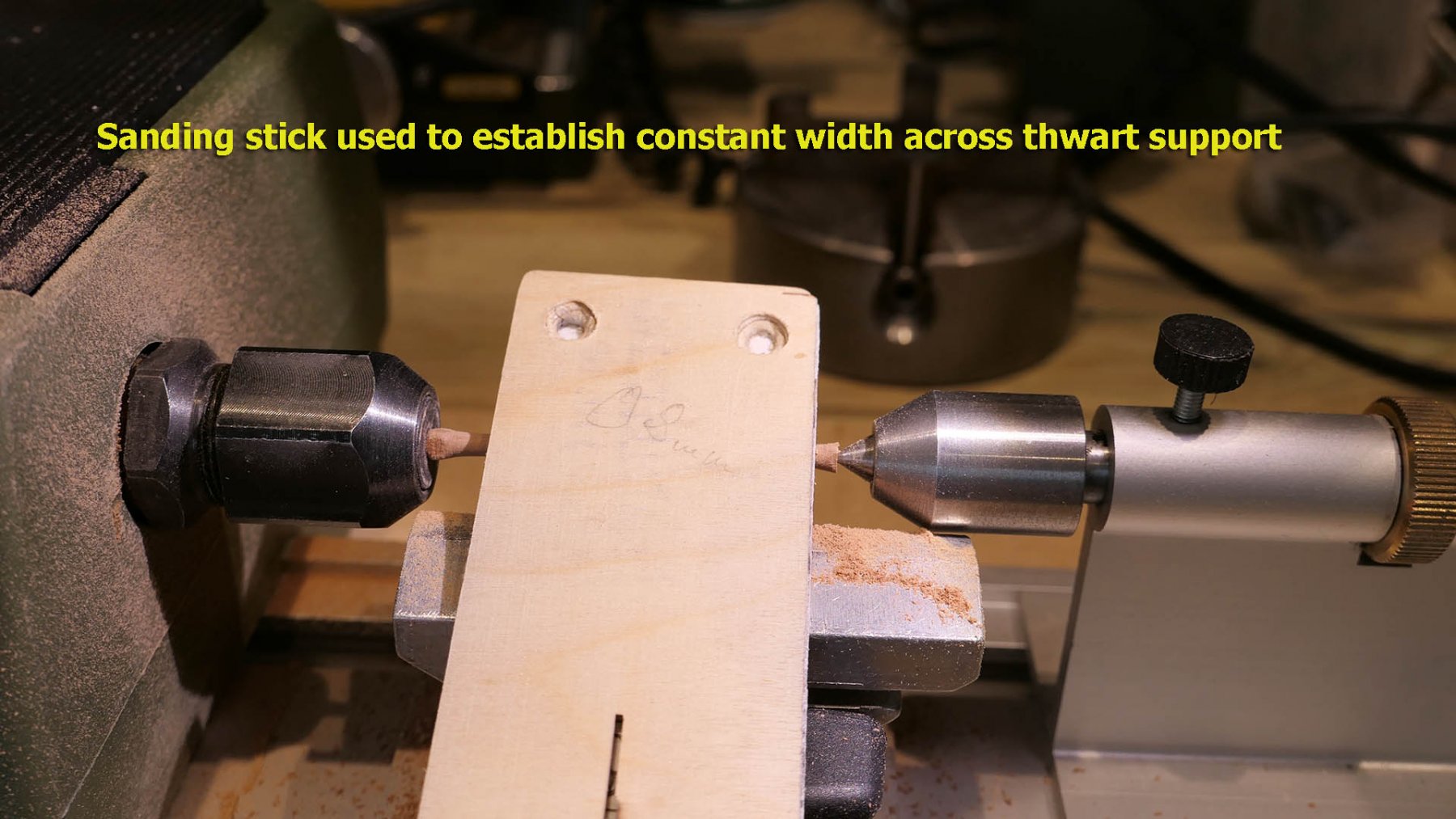
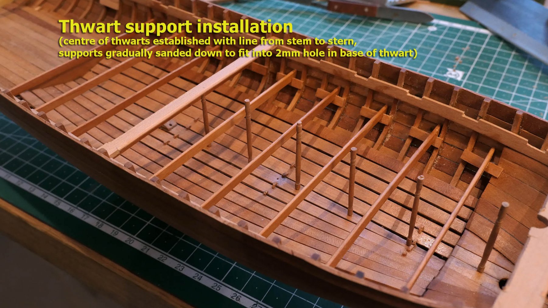
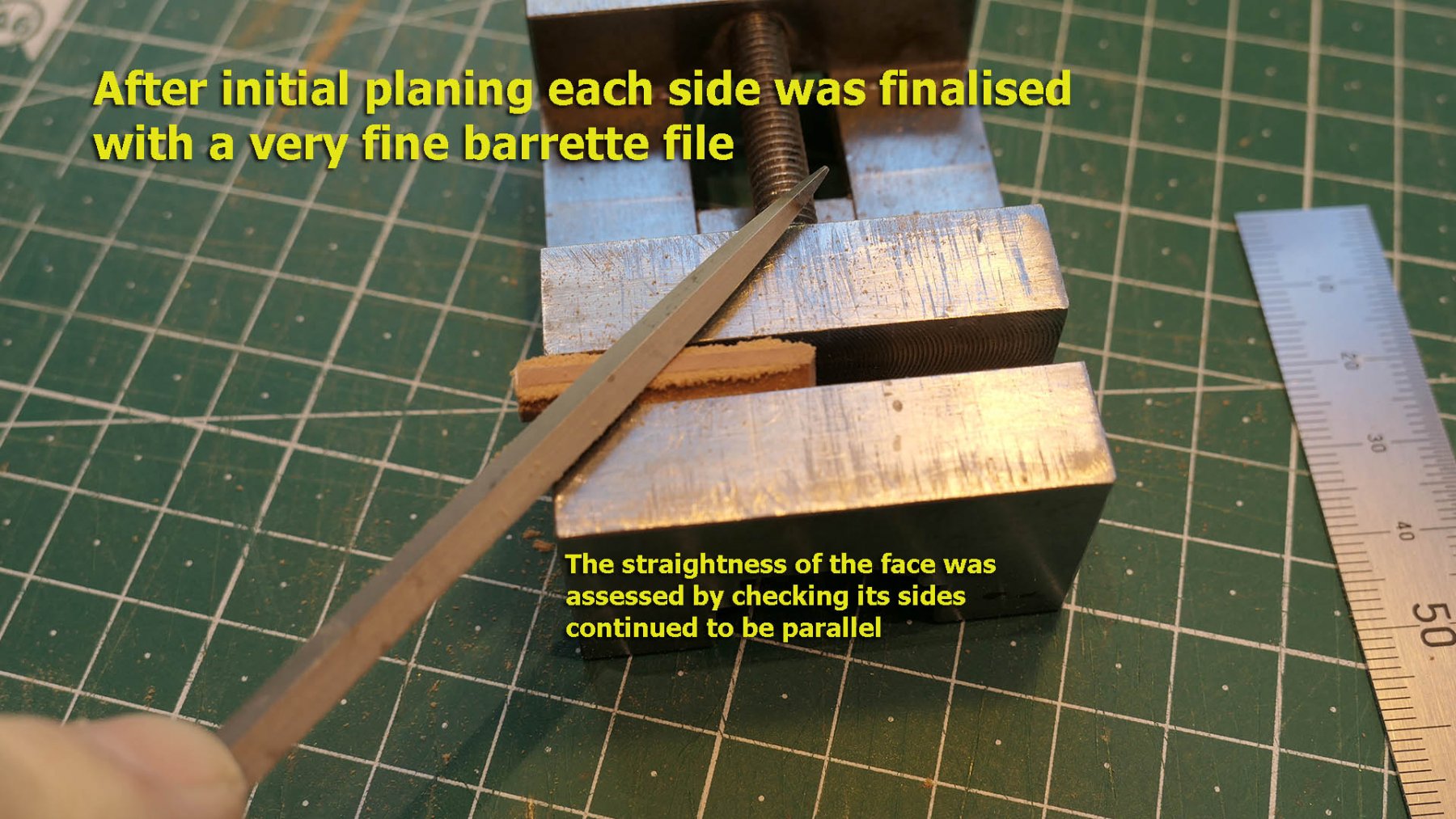
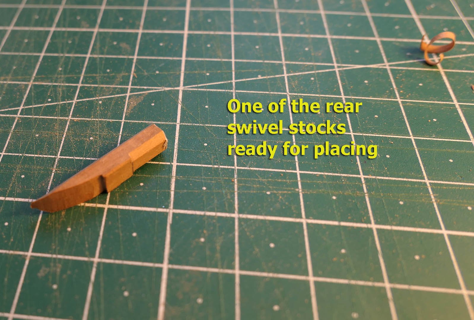
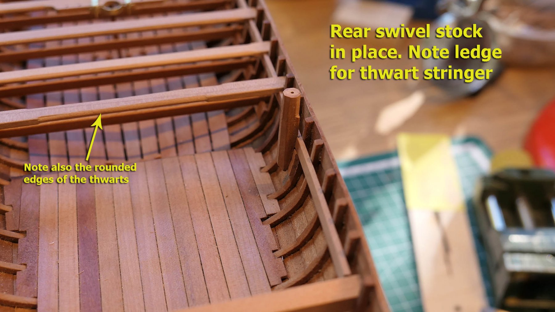
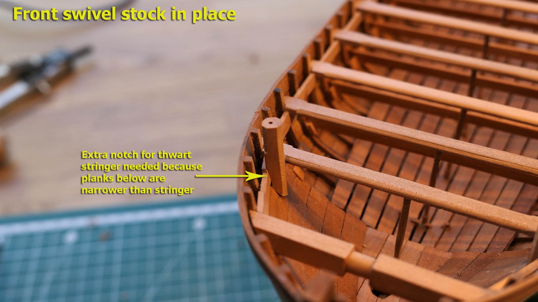
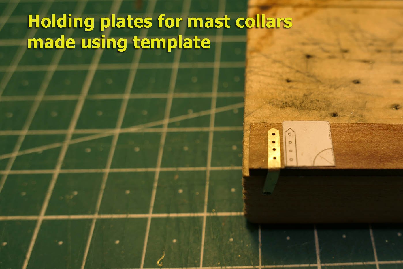
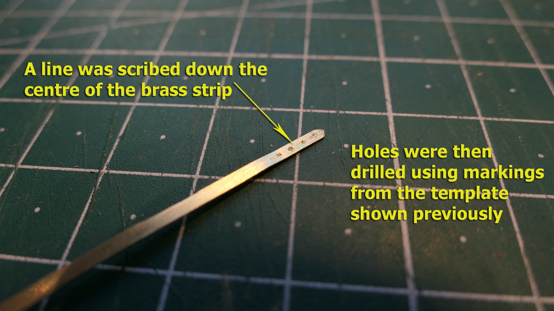
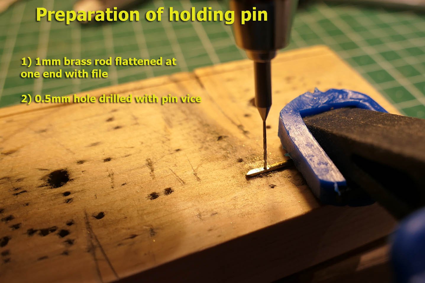
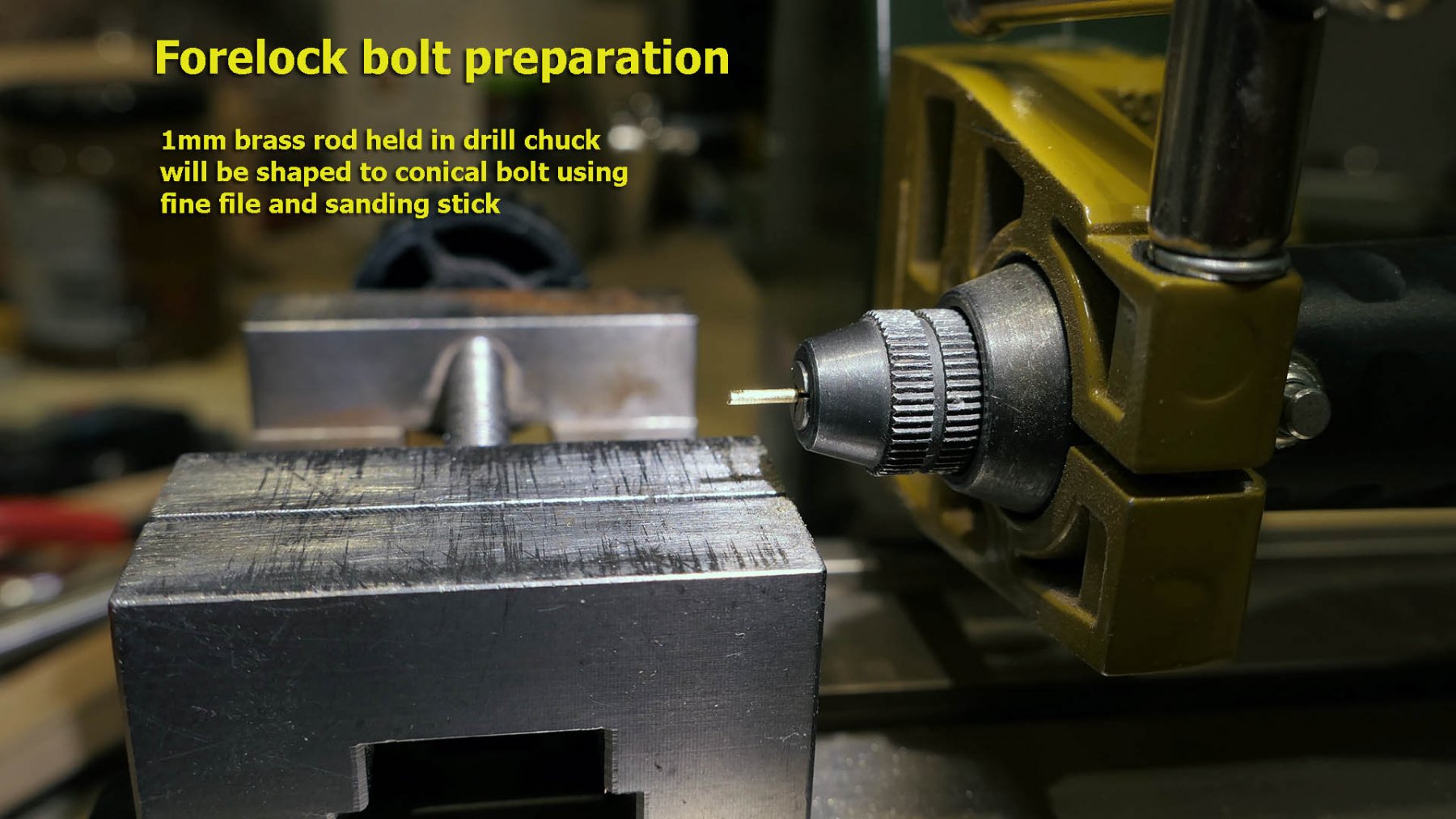
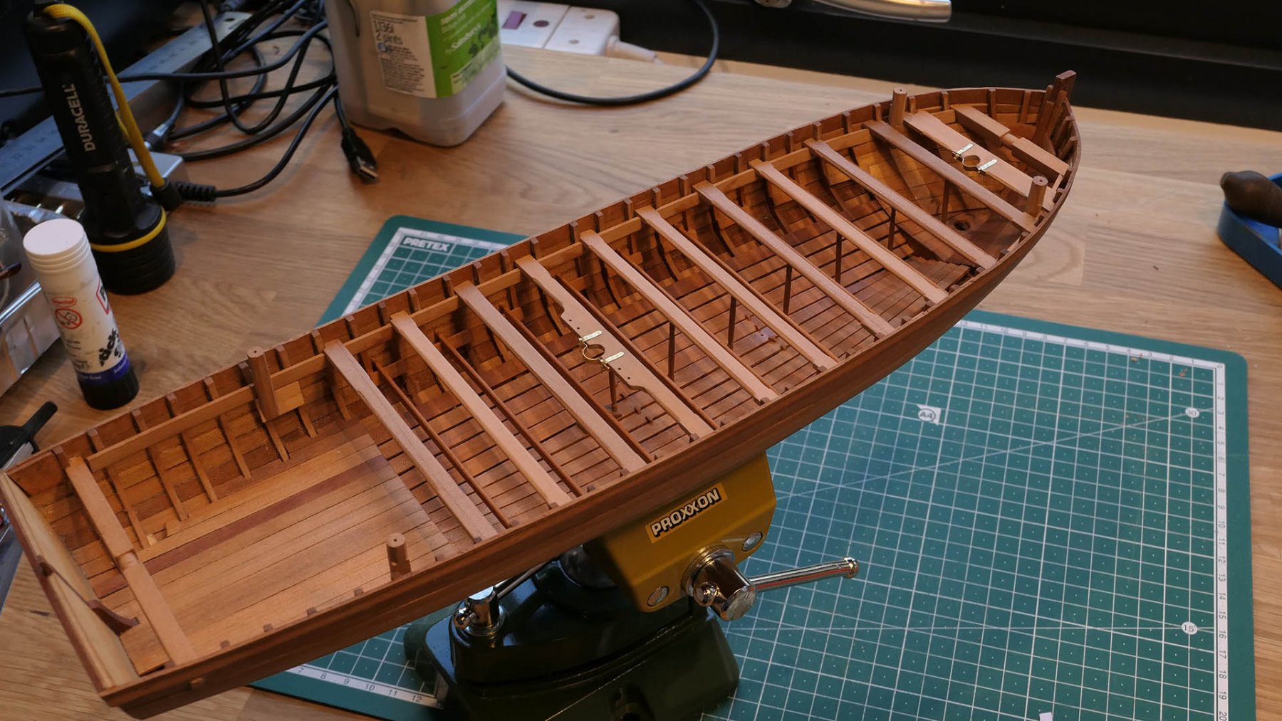
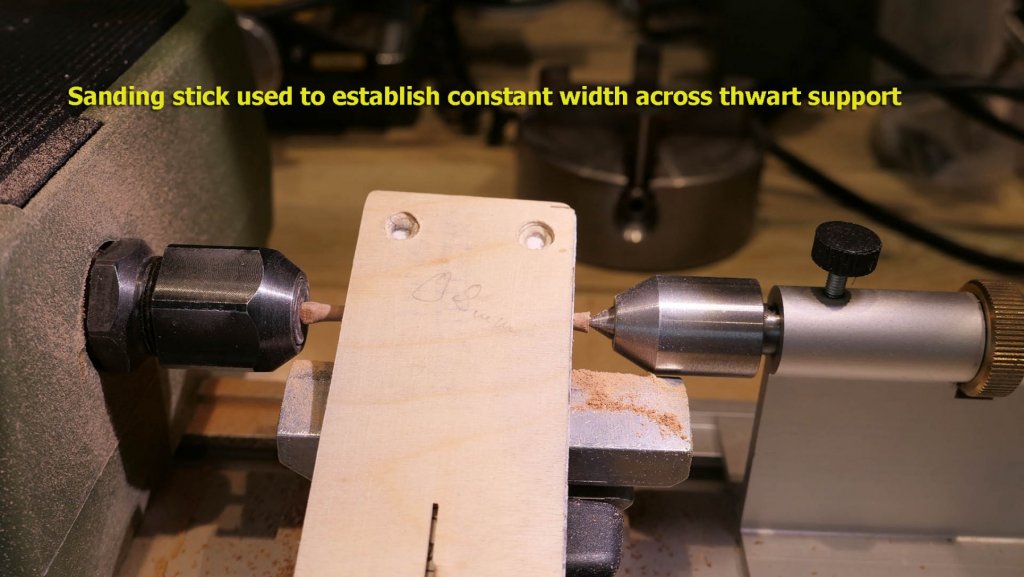
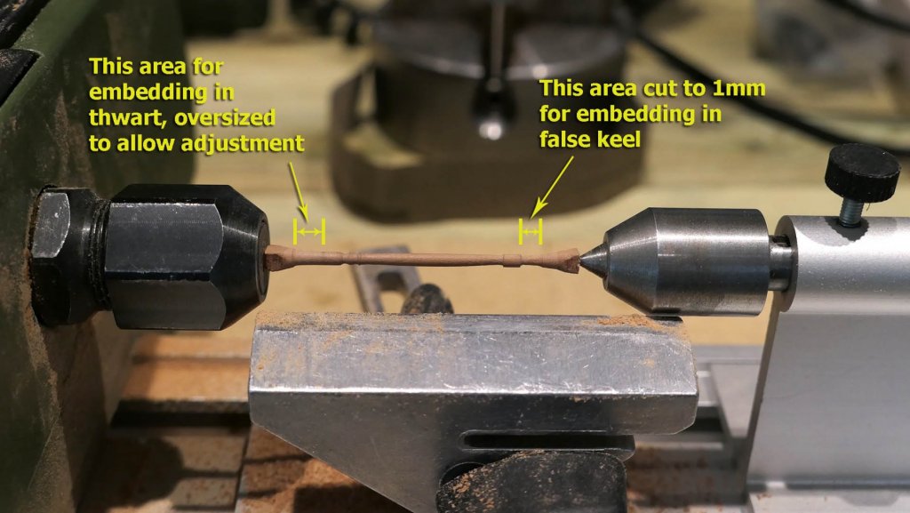
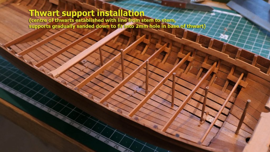
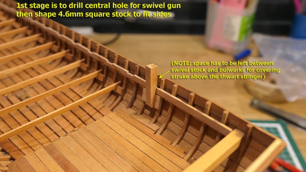
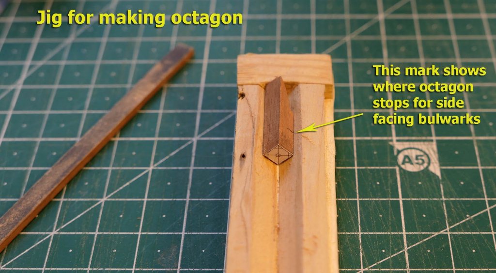
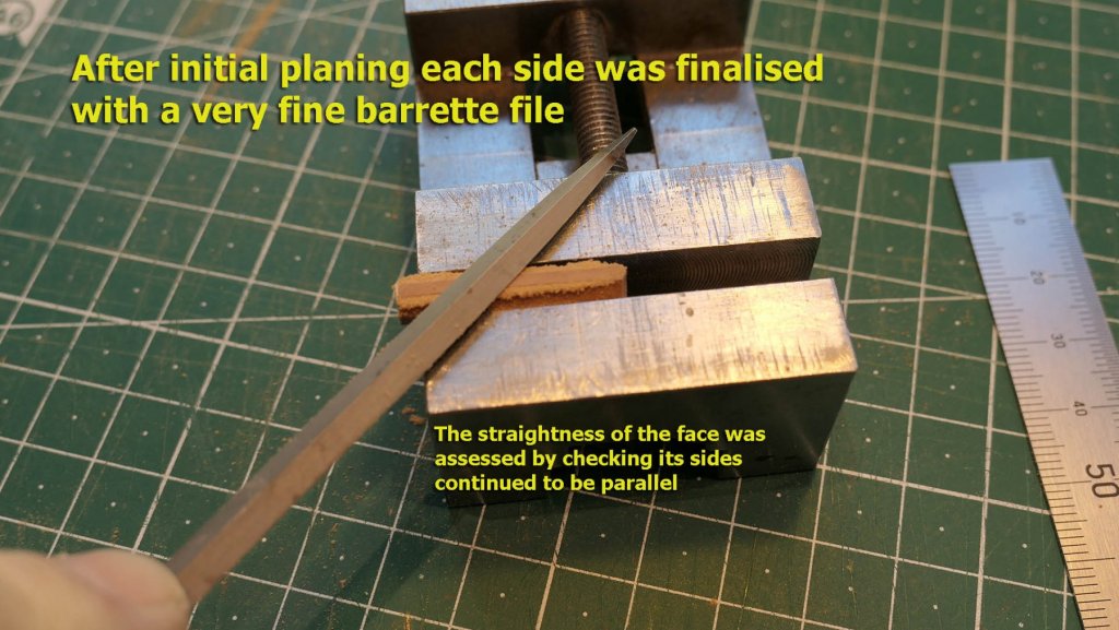
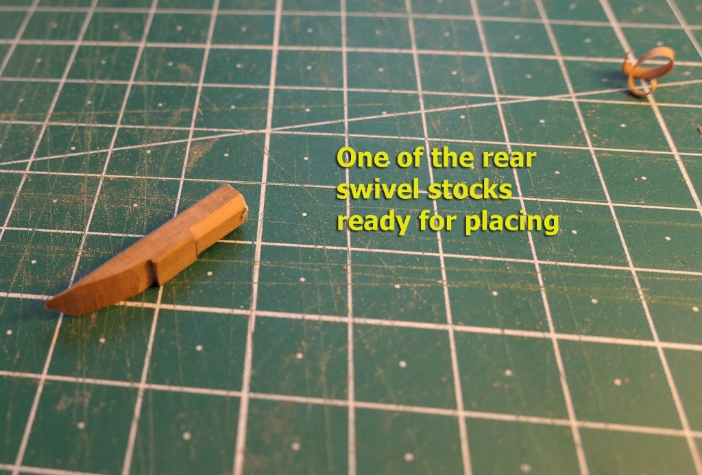
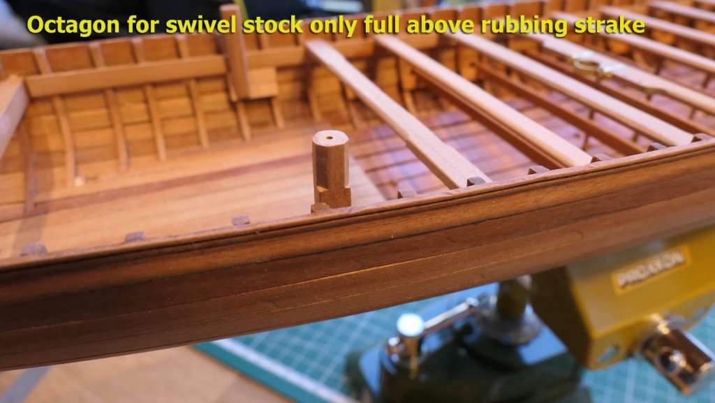
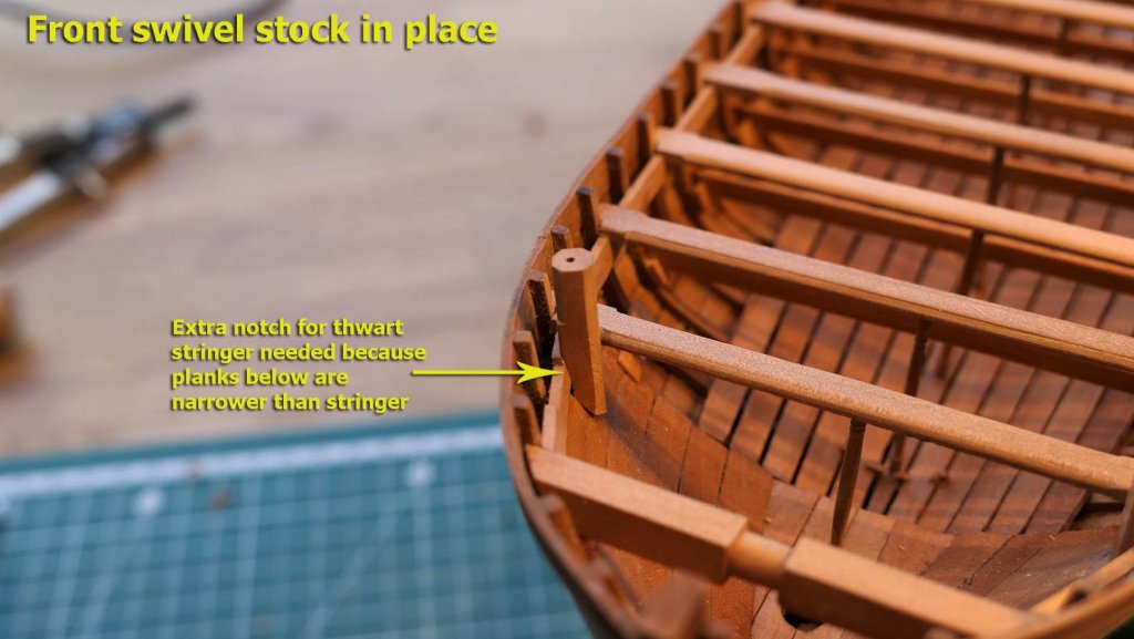
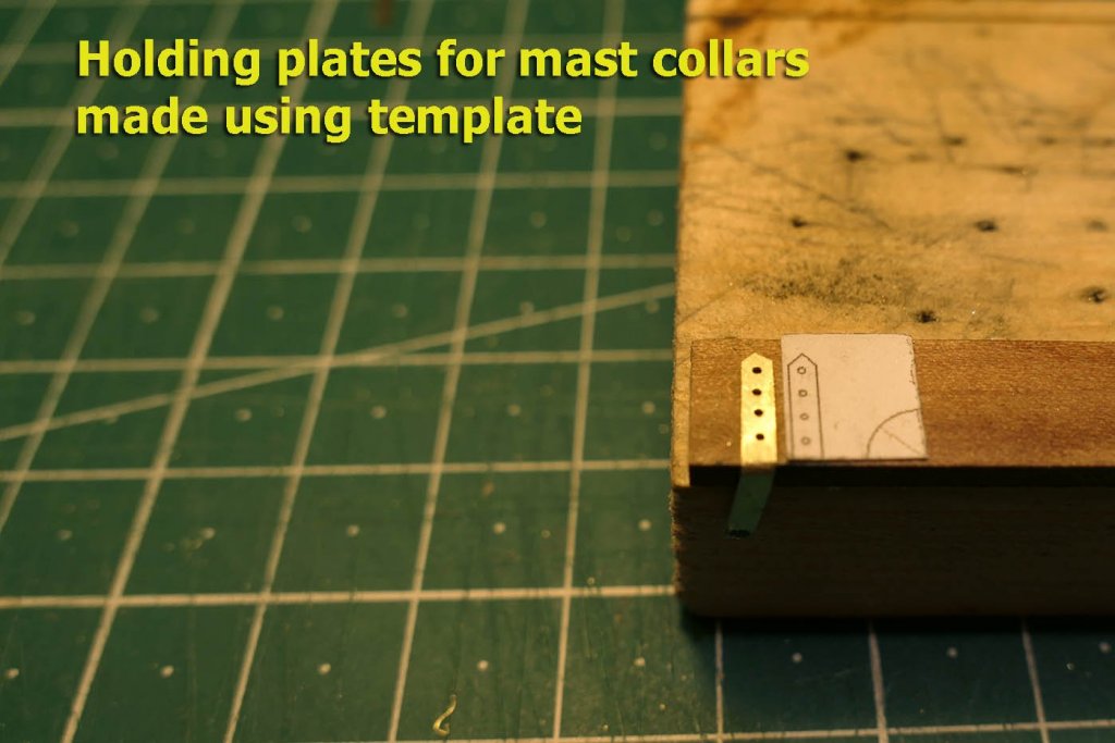
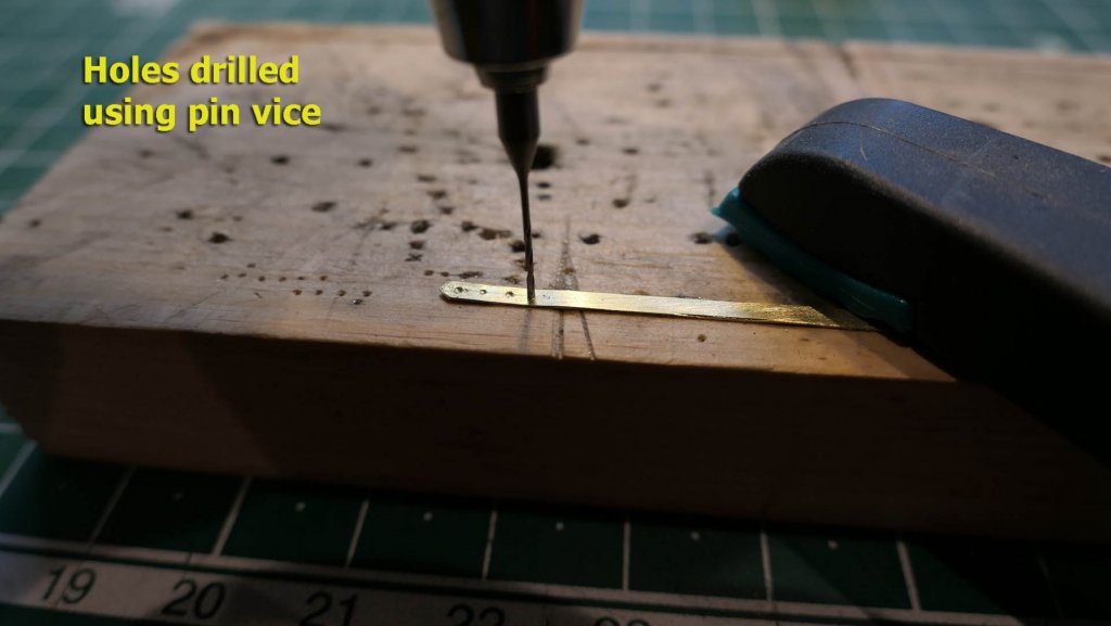
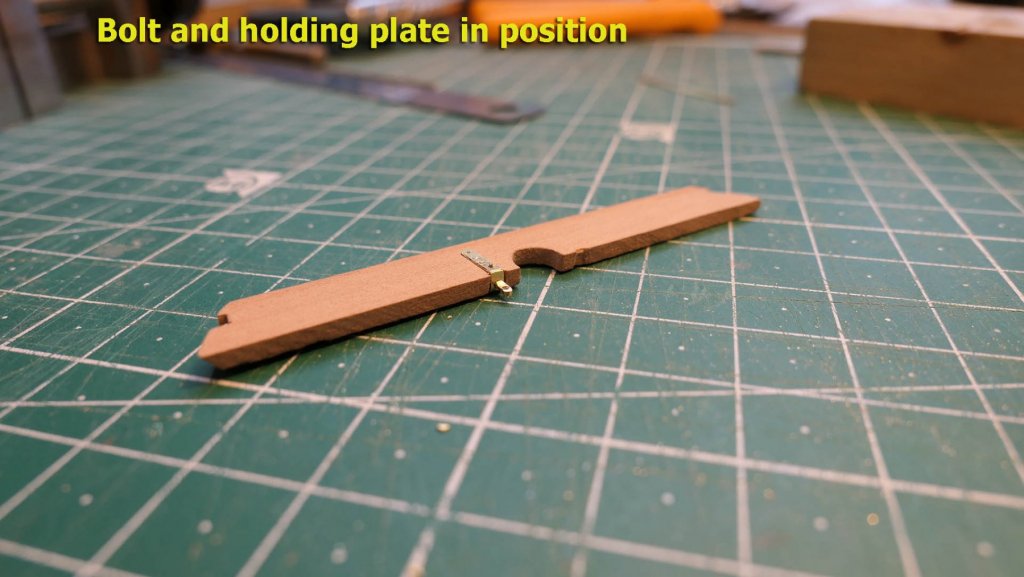
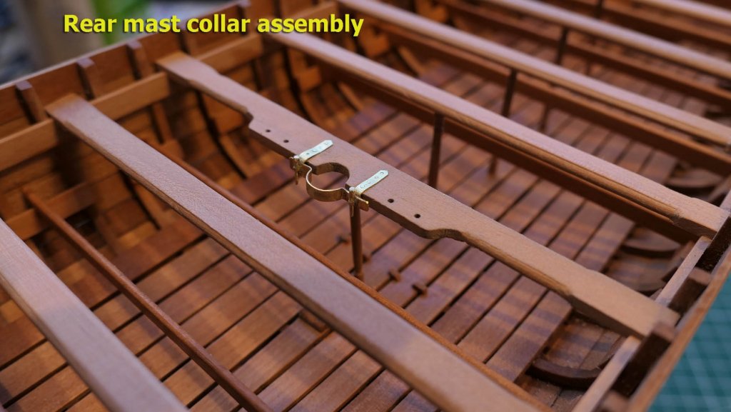
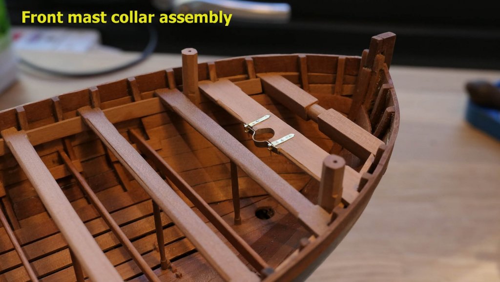
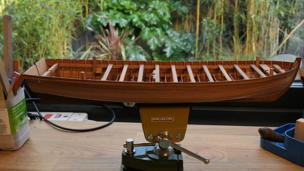
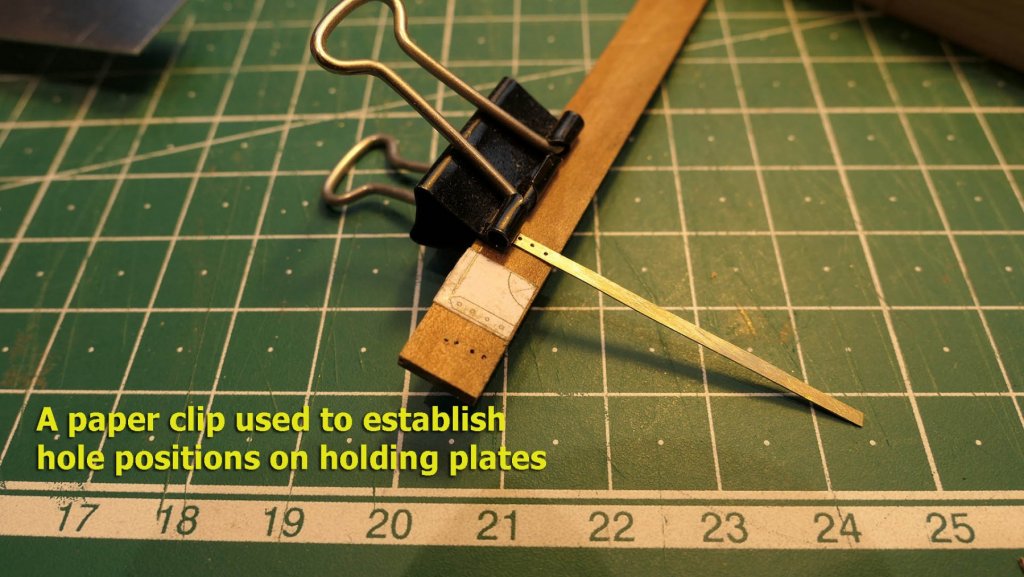
Thwart supports I experimented with making the thwart supports using a metal lathe, but in the end found that my Proxxon woodworker’s lathe was better suited. I also found that 3mm square stock was far easier to handle than 2mm square stock. In order to achieve a constant initial width I used a very wide sanding stick with 120 grit paper. If you’re wondering what the board is, it’s a zero tolerance insert for my bench saw that was discarded. When making the supports, I left plenty of head room top and bottom so that I could easily adjust the support to the correct height. It was great to see the thwart supports all lined up in a row, ready for the thwarts. I drilled a 2mm hole in the centre underneath each of the relevant thwarts (not all the thwarts have pillar supports) and then gradually sanded down the tops of the supports until they fitted snugly. Swivel gun stocks The swivel gun stocks turned out to be slightly easier to make than I expected. Even though I am still thinking whether or not to arm the boat, it would be very difficult to fit the swivel stocks should I decide to arm them later. The first stage is to drill in the stock the central hole for the swivel gun. I then cut the square stock to the shape of the bulwark. In my first attempt I had cut the squares into octagons before doing this and it ended up unsuccessfully as very fiddly. This way round (the way suggested in the guide) worked well. Lesson learned. One thing you have to watch out for when preparing the stock is to ensure that the stock will fit against the strake that covers the frames, so I used a small section of 1mm thick planking to check the depth. Cutting the octagon needed a little more care as not all the sides are cut to the full length. The side facing the bulwark only has an octagonal shape above the rubbing strake. I used a jig from a previous model to cut the first phases of the octagon, together with a template to mark the cuts from the top. The very first cuts were with a miniature block plane, but the finishing was done with a sanding stick and a fine metal file. The difficulty when cutting the octagon is ensuring the faces are straight. I just checked visually that the sides were kept parallel, and that seemed to work well enough. By the way, I have not made mention of the fitting of the thwarts themselves, so this is just to note the importance of using a template to scrape a rounded edge to the correct dimensions on the front and rear edges of the thwarts. Note that the front swivel stock has to have a notch cut to take the thwart stringer as the planks below are thinner than the stringer. This is not the case at the rear where the planks used to hold the stocks are the same thickness as the stringer. Mast collars The mast collars took me quite a bit of time as I have not worked with brass for a long time, so I had to re-learn some of the skills: notably cutting straight strips! The first stage was to make the holding plates for the collars. These have four holes for the nails (or bolts) that fix them to the thwarts. I used a template first to determine the position of the holes on the brass strips. In the following pictures I demonstrate the use of the templates with strips that have already been drilled, but you should get the idea. I also used a paper clip to hold the strips to the wood strip while marking where the holes should go. Having marked the position of the holes in one direction, I scribed a straight line down the centre of the strip and then drilled the holes accordingly. I used a handheld pin vice to drill these holes at first, but later on I changed to drilling them with an electric drill as it took such a long time by hand. All the same, even with the drill, I still started the holes with the pin vice as it is so much easier to determine the position by hand. I then drilled the holes for the pins that would hold the mast collar to the holding plates. On my first try I had stupidly placed the nails in the holding plates forgetting that this would make the drilling of the pin holes very difficult, no, impossible. So I had to start all over again. I also learned, after completing the main mast collar, that in order for it to lie flush to the thwart it would be a good idea to cut grooves for the holding plates. The holding pins themselves turned out fairly easy to make. I took a piece of 1mm brass rod and flattened one end with a file. I then drilled a 05.mm hole in it for the forelock bolts. The pin was then shaped to a conical form using the Proxxon drill and a file as well as a sanding stick. The following shows the plate and holding pin in position, without the forelock bolt. And now here’s the complete assembly, forelock bolts and all. You’ll notice I have not blackened the brass. The reason is simple: I haven’t yet found a way of blackening it and then assembling all the blackened bits without damaging the blackening. Mostly I end up with a rather blotchy effect if I do. Given the positioning of the collars, any imperfections will be glaringly obvious. So I’m making do with just the imperfections of the construction being glaringly obvious. Perhaps one day I’ll learn the trick. I’m lucky that I managed to squeeze in these few steps before my surgery next week. I’ll see what I can do before then, but I doubt very much I’ll be posting results for quite a while as I have a feeling that the lodging knees will be quite complex to make and fit correctly (the next step). All the same, keep a lookout if you're still interested in following! With thanks again to all those who've given me comments, advice and the thumbs up. It's always motivating and very helpful. Tony


- 124 replies
-
- 19
-
-
- longboat
- Chaloupe Armee En Guerre
- (and 1 more)