HOLIDAY DONATION DRIVE - SUPPORT MSW - DO YOUR PART TO KEEP THIS GREAT FORUM GOING! (Only 24 donations so far out of 49,000 members - C'mon guys!)
×


tkay11
-
Posts
1,827 -
Joined
-
Last visited
Content Type
Profiles
Forums
Gallery
Events
Everything posted by tkay11
-
 How's progress? Tony
 -
Thanks a lot, Danny, for the meticulous log showing the individual steps and methods. I also appreciate your noting the time it took for several of the steps. In all a real help to others, as well as a good reminder of the attraction and skills held by card modelling which differ so much from those of wood modelling. I find I have to have a very different mindset when approaching card modelling and your log demonstrates perfectly that mindset. Tony
-
I hope you're having a nice break, Radek. Will you be coming back to this build, or is it still on hold? I really like your guidance on techniques in card modelling, so am looking forward to more! Tony
-
It might be construed as a dangerous weapon. Tony
-
We have thousands of CEOs all over London. They're Community Engagement Officers -- the new title for Parking Wardens. Tony
-
Lovely work, Phil. Tony
-
Filler Blocks
tkay11 replied to olopa67's topic in Building, Framing, Planking and plating a ships hull and deck
wefalck: Out of interest I thought I'd find out where to buy acrylic foam in the UK. I can't find any sites, including Plexiglas, that talk of acrylic foam except in relation to acrylic foam tape. I found a reference to syntactic foam as another name for acrylic foam in a paper on flexible acrylic foams as a carrier for speciality tapes. That led me to look up syntactic foam on Wikipedia, where it says: "Syntactic foams are composite materials synthesized by filling a metal, polymer, or ceramic matrix with hollow spheres called microballoons or cenospheres or non-hollow spheres (e.g. perlite). In this context, "syntactic" means "put together." The presence of hollow particles results in lower density, higher specific strength (strength divided by density), lower coefficient of thermal expansion, and, in some cases, radar or sonar transparency. A manufacturing method for low density syntactic foams is based on the principle of buoyancy. The term was originally coined by the Bakelite Company, in 1955, for their lightweight composites made of hollow phenolic microspheres bonded to a matrix of phenolic, epoxy, or polyester." So I looked up syntactic foam suppliers, and their offerings include rigid, high strength composites of epoxy resin and hollow glass microspheres. Would this be the material you refer to? It's probably very expensive. Would it be very different in properties to the generally available PVC foam or foam board, which sounds similar to polyurethane foam and is very crumbly in character? Tony -
Hellmuht: I'm sending you a Personal Message with Dane's email so that you can negotiate directly. Tony
- 124 replies
-
- 1
-

-
- longboat
- Chaloupe Armee En Guerre
- (and 1 more)
-
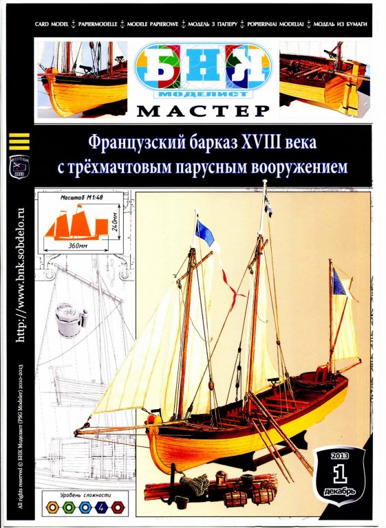
Thanks for posting your model of the Chaloupe, Hellmuht. It's a pity you don't have a build log for it. But I've been admiring your build of the Bounty, and your post led me to your log of the build of the Spanish Longboat. While I'm recovering from surgery (which has prevented me from working on the Chaloupe for the moment), I've been looking at a card kit from Russia for an 18th Century French longboat at a scale of 1:48. I'm still working through translating it, but it has a very interesting construction method -- similar to Chuck's longboat and to your Spanish one -- and it's entirely card. Dane, who developed the kit, posted his completed build on this forum in 2013 at It has particular interest in that it also gives plans for all the extras (buckets, barrels, anchors, hooks) and very full rigging plans. It was also very cheap (about €25 including tracked postage). The instructions are incredibly detailed (far more than most card kits), and as a result it is well worth the effort in translating them. You can see the creation of the kit from its inception and its subsequent build in Dane's log at http://only-paper.ru/forum/85-12867-1 The cover of the kit (which you have to order from Dane directly) is: Tony
- 124 replies
-
- 2
-
-
- longboat
- Chaloupe Armee En Guerre
- (and 1 more)
-
I agree it's a beautiful model, G.L., but it's by Hellmuht, who's just showing me the possibilities and offering help should I need it. Tony
- 124 replies
-
- 2
-
-
- longboat
- Chaloupe Armee En Guerre
- (and 1 more)
-
Filler Blocks
tkay11 replied to olopa67's topic in Building, Framing, Planking and plating a ships hull and deck
I used balsa as filler for all the bulkheads in my first build (Sherbourne). I found it wasn't very good with glue for the planking, but maybe that was my fault. It doesn't hold nails or other fastenings either in case you are thinking of going down that route. It certainly was better than nothing, though, and extremely easy to shape. I'd go with pine or basswood/lime in future as suggested by Jaager. Tony -
Gosh! Three complementary and very useful replies all at once! Thanks very much vossiewulf, Bob and Michael. Very interesting indeed. Tony
-
Thanks, Alex. I'll get back to you on this as I'm still debating my next build. Tony
- 227 replies
-
- 1
-
-
- cumberland
- 74 gun
- (and 1 more)
-
Thanks for the info, Alex. I didn't see a price for the drawings/plans for the Imperial Yacht Queen Victoria. Have I missed something? Tony
- 227 replies
-
- 1
-
-
- cumberland
- 74 gun
- (and 1 more)
-
Thanks very much, Chuck and Wefalck. I think that gives me all the answers I need to satisfy curiosity! Tony
-
Thanks, Welfalck. I suspected it was through software. I realise that 3D CAD can show the spiled planks in their fully fitted form. Can it work out the shapes when flat, before bending to the curvature of the hull. I can't see how to do that with my 3D TurboCAD (though admittedly I am only really conversant with it in its 2D form). Tony
-
Just out of curiosity, I was wondering how kit makers are able to provide pre-spiled planking. I have just received one such Russian kit for a longboat in card, and have seen others (such as Chuck's longboat) with laser-cut pre-spiled planks. Is this done with some computer software, or is it that when making a pre-production model the spiled planks are carefully traced, or that paper is laid on the frames or shell to achieve the same outlines? Tony
-
Milling is fun, isn't it! Nice result. Tony
-
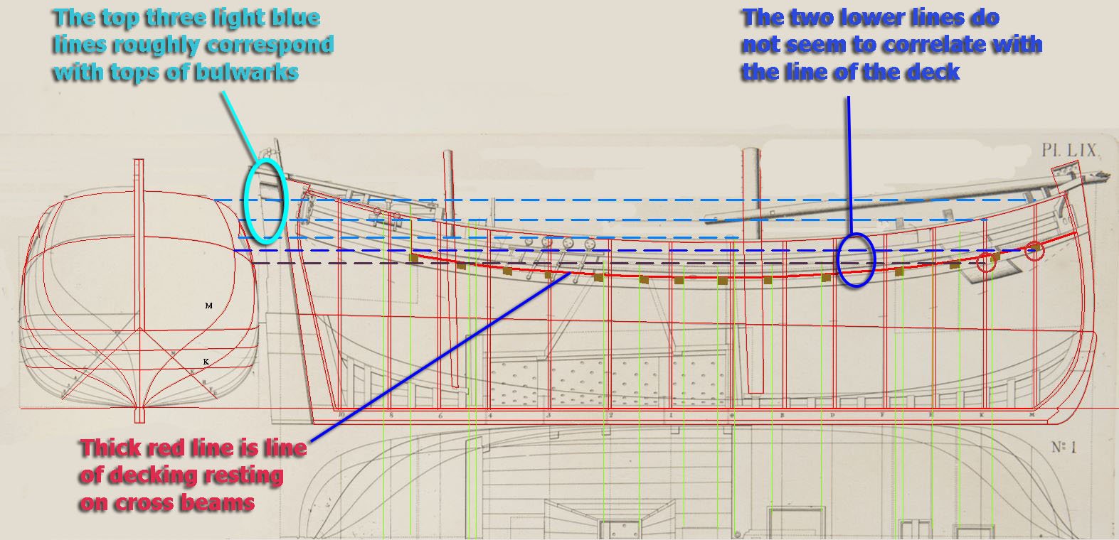
Thank you very much for your advice, Ab. I took the run of the deck from what I take to be the beams supporting the deck, above which runs a dotted line. I see the outline of the wale as quite separate from the dotted lines running on top of the beams. I outlined the beams as brown squares in the drawing, but I quite see that this could represent the central spine and that I had not taken into account the camber. I agree with your analysis: the point is just to get on with it and not be too picky about a couple of millimetres (equivalent to 14cm at full scale), when the plans are themselves photos or scans of original work, and were possibly drawn up just to give the idea of the ship. I also agree that the safest thing is to work from the half-breadth plan to make the bulwarks for the model as correlation with the sheer plan might be too difficult. Thanks again for the help! Tony
- 65 replies
-
- 4
-
-
- fish hooker
- fishing
- (and 2 more)
-
Ab, I have followed your log with great interest, and while I am recuperating from surgery have been drawing up the plans just to make the hull of this fish-hooker in card before I can get back to my chaloupe model. I have started this by tracing the lines in CAD. Unfortunately, perhaps because of my failure to understand the plans, I cannot seem to reconcile what I take to be the line of the deck on the sheer plan with that on the half breadth plan. You will see in the following tracing the lines for the fore bulkheads K and M together with the general outline for all the fore bulkheads. On the right there is the sheer plan on which I have drawn the station lines for the bulkheads. I the uppermost three lower lines on the half-breadth plan do seem to signify roughly the tops of the bulkheads and the lines of the deck, but the lowest two horizontal lines from what I take to be the line of the deck on the half-breadth plan do not seem to match the line of the deck on the sheer plan for station lines K and M (they are out by about 2mm each at a scale of roughly 1:70). I am pretty convinced that either I have not understood the plans correctly or that the original lines were not drawn with the level of accuracy necessary to a CAD drawing, so I would be very grateful if you could let me know whether I am being far too picky or just plain wrong in my interpretation of the plans. On the drawing I have erased all the mast drawings for the sake of clarity. Thanks, Tony

- 65 replies
-
- 3
-
-
- fish hooker
- fishing
- (and 2 more)
-
Interesting comment about the rudder coat. The few contemporary models of cutters I have seen had a different design, with a box-like construction over the rudder, so I wondered whether or not there was extra coating within the boxing for those cutters. Do you have any sources on this, or is it an informed guess based on your usual historical thoroughness? Some of the builders of the Sherbourne (myself included) put rudder coats on. Do you think this is a mistake? It's also a lovely tiller you've made. Do you have any comment about the strapping or roping that is sometimes seen on the handles of tillers, purportedly to give more grip? Tony
- 574 replies
-
- 1
-
-
- cheerful
- Syren Ship Model Company
- (and 1 more)
-
Just in case you haven't seen it, in addition to Bindy's build and Maurino's gallery on this forum, there's a build of the Leudo on YouTube which you might find helpful at: Tony
-
Doris uses the term 'foil' and her suppliers are at https://www.tapety-folie.cz/drevo/c-2404/. These look like pva or some kind of glue-backed pliant plastic. She stretches and shapes it with heat. Tony
-
We had a discussion about this in August 2016 in relation to stowing the anchor on the Sherbourne. In the end I followed the diagrams from Harland's Seamanship in the Age of Sail. The general discussion was at I showed this on the model at I hope this helps. Tony
- 714 replies
-
- 3
-
-
- lady nelson
- victory models
- (and 1 more)