HOLIDAY DONATION DRIVE - SUPPORT MSW - DO YOUR PART TO KEEP THIS GREAT FORUM GOING! (83 donations so far out of 49,000 members - C'mon guys!)
×


tkay11
-
Posts
1,829 -
Joined
-
Last visited
Content Type
Profiles
Forums
Gallery
Events
Everything posted by tkay11
-

Preprinted lines
tkay11 replied to achuck49's topic in Building, Framing, Planking and plating a ships hull and deck
If you're thinking of Photoshop, version CS2 is still produced by Adobe for free download. It doesn't have all the bells and whistles of the latest versions but does function perfectly well as an image manipulator, re-sizer with layers, and is very easy to use. Have a look at https://www.redmondpie.com/download-adobe-photoshop-cs2-for-free-legally-while-you-still-can/ There are sites where you can download it without having an Adobe ID, but going through Adobe does guarantee it has no malware. Gimp is still a good option, but I am used to Photoshop and find it easier to use. Tony -
Re: www.massiv-holz-werkstatt.de Interesting, and thanks for the info about MassivHolz, Dirk. I've bought from Arkowood in Germany and the owner of that (Oliver König) not only speaks English but also responds readily to communication (but the website is only in German, so you'll need Google Translate for that or some web translation). His prices are on par with MassivHolz but for delivery are much lower than MassivHolz. Delivery is on the slow side (about a week from Germany to the UK) as he probably mills the orders himself when they come in. Others have commented from the French forums that Arkowood is their preferred source, and I think a few from the UK who use this forum have also bought from him. Tony
-
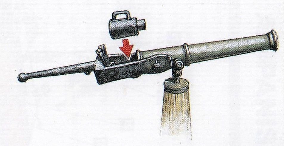
I am considering whether to arm my 'armed' longboat of 1834, and while doing so I'm looking at the type of swivel guns used. In all the models of this I've seen a standard muzzle-loading swivel gun is depicted, as it is in the plans of M.Delacroix from which I am working. However, I was wondering whether this type of longboat might have used breech-loading swivel guns as these were popular at the time and provided more rapid fire than could the muzzle-loaders although they were less reliable. So if there's anyone who's knowledgeable about this please do chip in with your opinions. It may be that I don't end up putting any armament on the longboat, but I'm still interested in the question as may others be when considering the type of swivel gun to use on their models. The following is an illustration of a breech-loader that was put up on Pinterest by Brian Walters Thanks Tony
- 9 replies
-
- 1
-

-
- swivel guns
- cannon
- (and 1 more)
-
Thanks, Griphos. It's the Proxxon Precision Steel Vice PM40 catalogue number 24260. It has a jaw width of 46mm, clamping capacity 34mm, total length 70mm. There is also a very nice slightly larger one, the PM60, with jaw width 60mm, clamping capacity 42mm, total length 100mm, catalogue number 24255. I think there's a nicer version of the PM40 in the USA, but I can't find a picture or catalogue number. Tony
- 124 replies
-
- 2
-
-
- longboat
- Chaloupe Armee En Guerre
- (and 1 more)
-
Well spotted on the hawse holes. I kept only two and can't remember the discussion around them. With regard to the forward gun port it would have been very tricky to set up one of the cannon in the area because of the windlass, bowsprit supports and pin rail. You'll see that I adjusted the pin rail so that it was along the axis of the boat, but even then there wouldn't have been much room. There was also the question of getting the gun over the windlass. I think we assumed that the forward ports would only have been used in exceptional circumstances and so left them empty. You'll have seen from the build logs that there was extensive discussion about whether gunport lids were fitted. There is one shown in one of the plans, so some builds included them. However there were contemporary cutters without such lids. You can't go wrong if you want to fit them, so it's up to you. It'll give you nice practice anyway! Keep up the good work, Tony
-
Thanks very much, Hellmuht, and thanks to all who've been giving me the thumbs up! I have to agree that the model does gain by it, but my wife didn't notice it at all. For most people who aren't into modelling it's probably a bit like a wort on a nice skin! Tony
- 124 replies
-
- 1
-
-
- longboat
- Chaloupe Armee En Guerre
- (and 1 more)
-
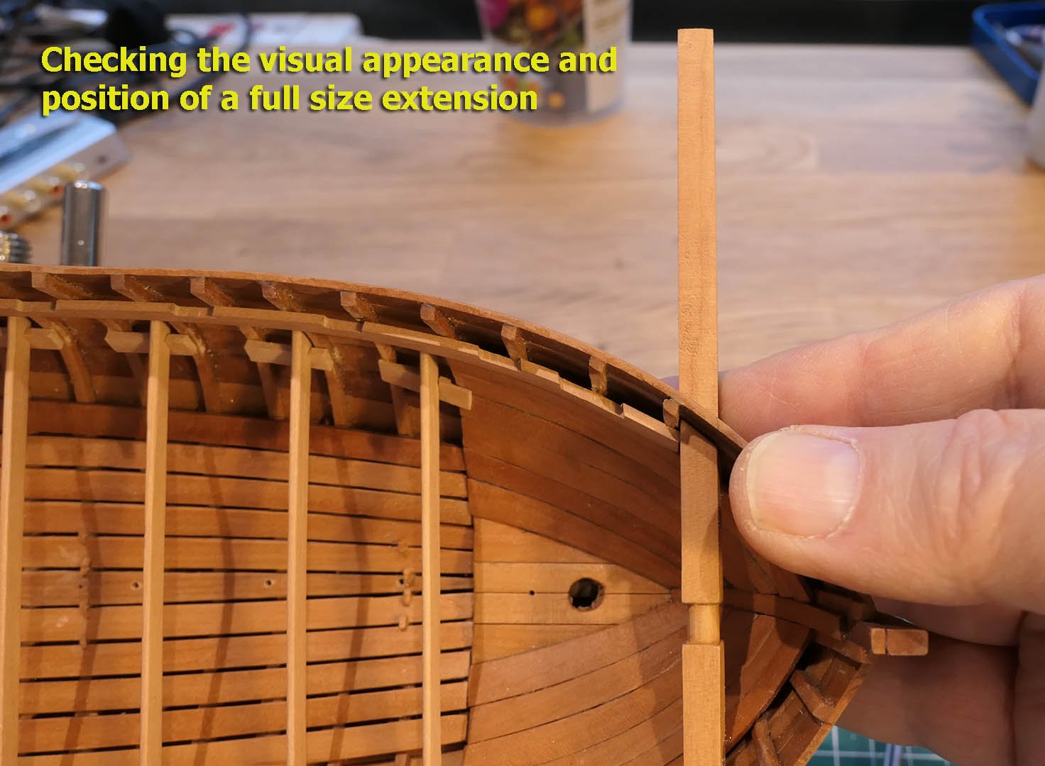
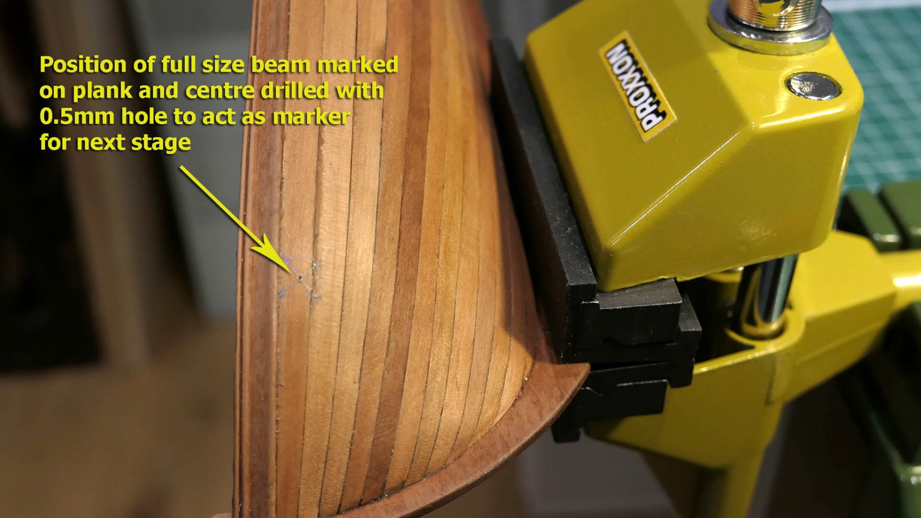
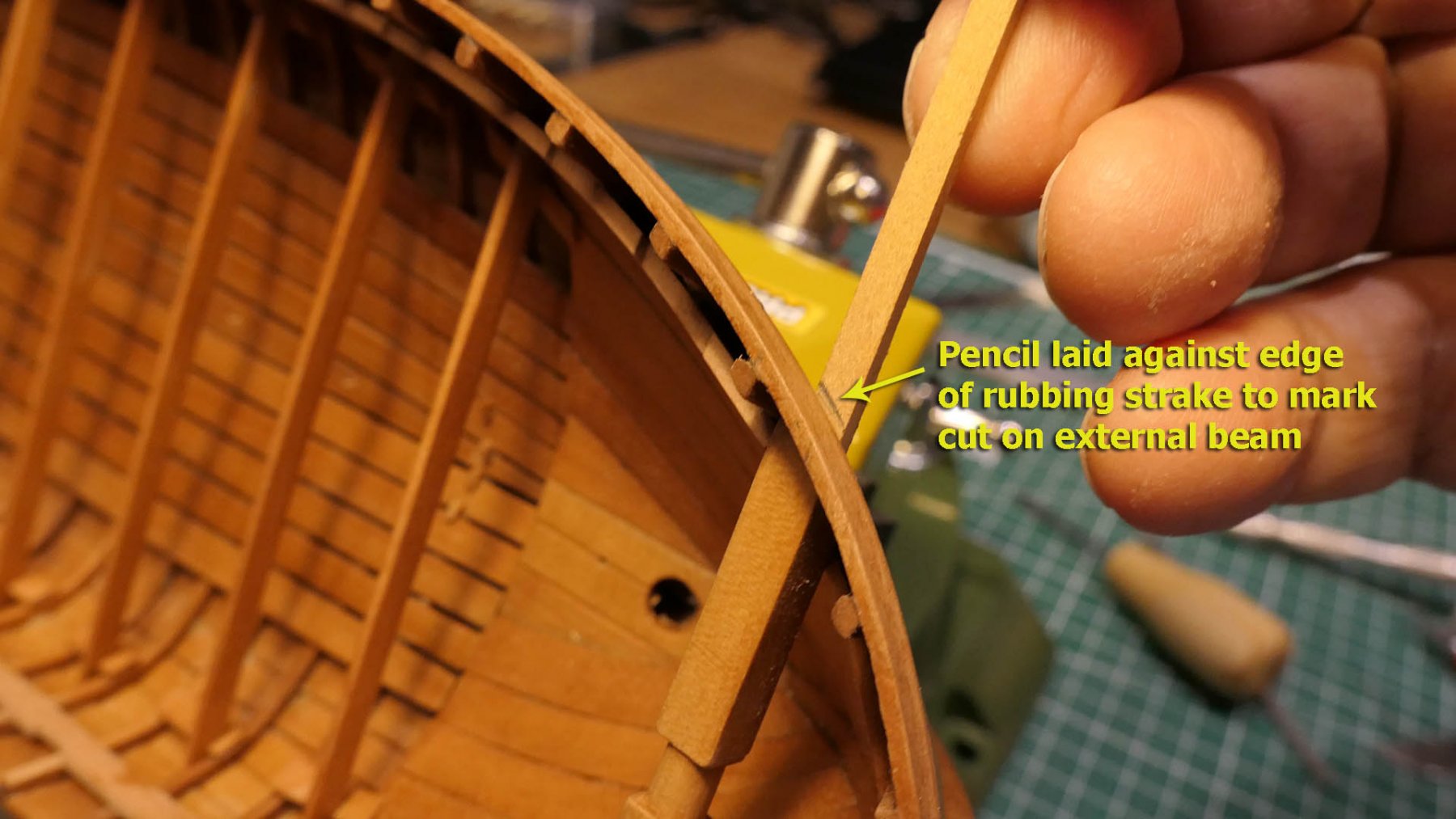
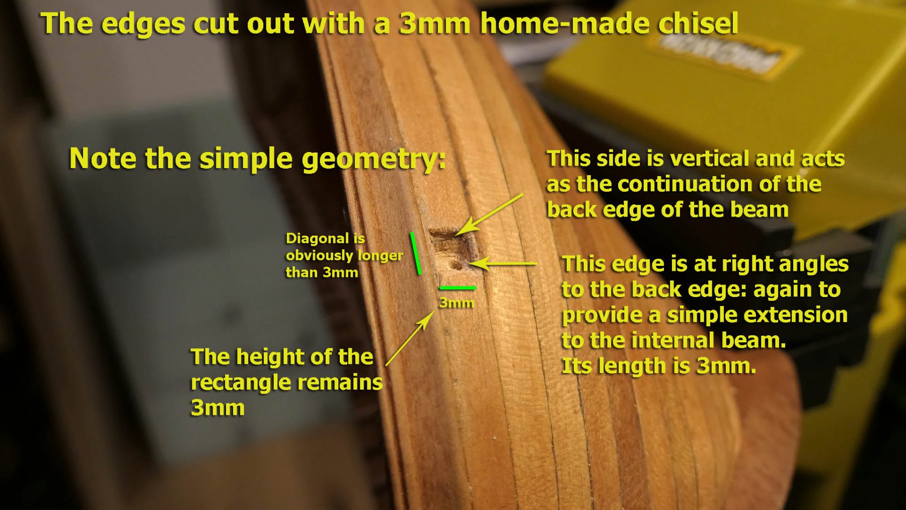
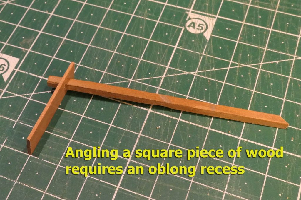
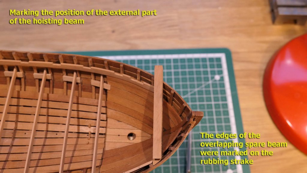
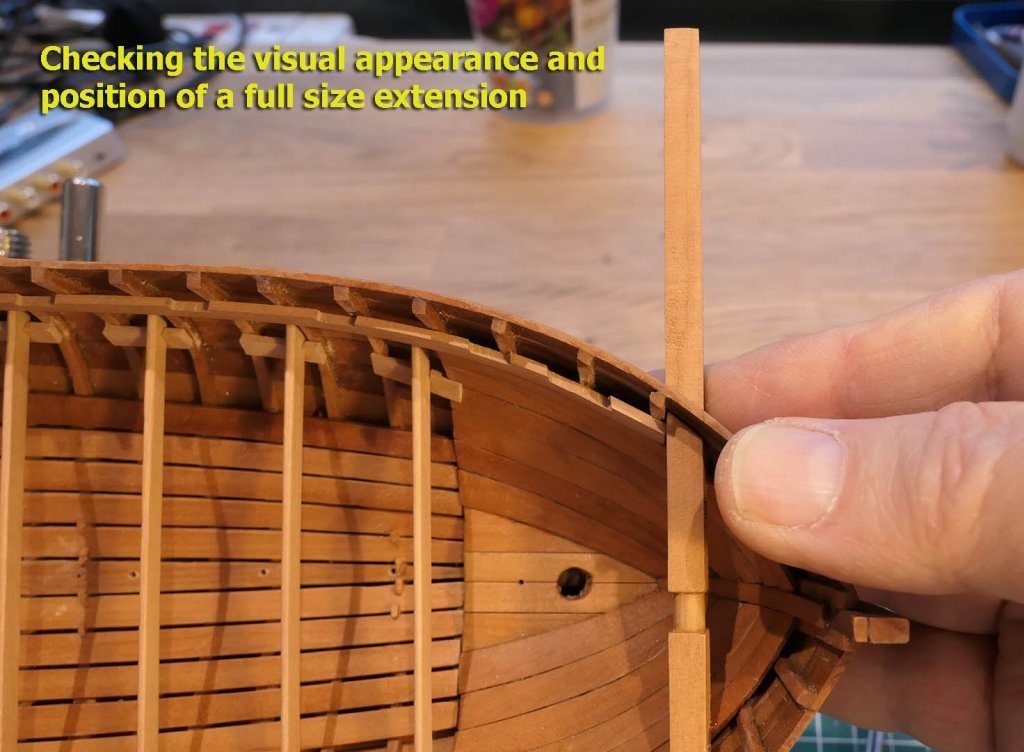
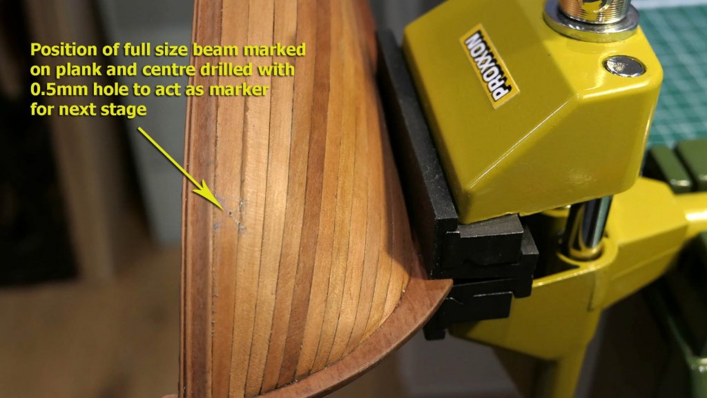
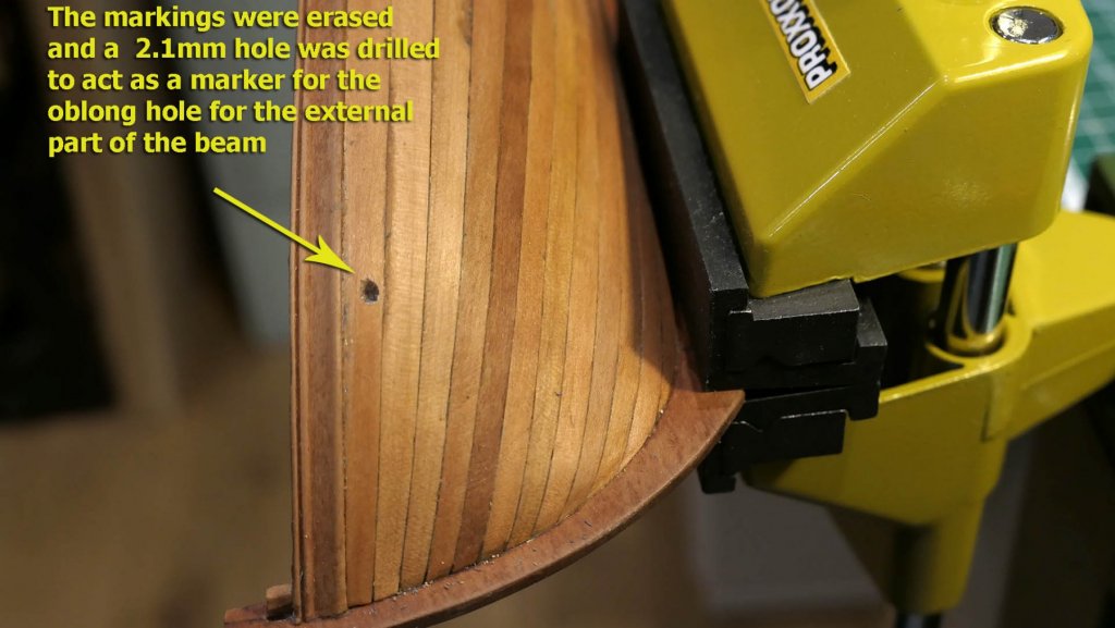
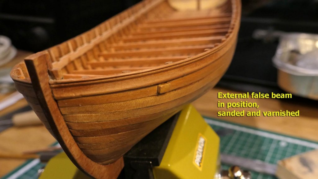
More on the hoisting beams Thanks, Michael. You're right about the imperfections. There's lots more and I try to bring out all of them as I go along. Anyway, you'll be interested to see that I took up your challenge and worked out a way of doing the false beam ends. It's not perfect at all, but it was at least fun to work at it. After my reply that I was reluctant to work on making the false external parts of the hoisting beams, I thought I’d experiment a bit with cutting a 3mm square in a piece of scrap wood. This started to reveal to me the geometry of the fixing. In order to place a square piece of wood at an angle to a surface, the hole of course cannot be square. It has to be oblong. It is this that had confused me when I had first contemplated the job: I had been thinking of shaping the wood to fit a square hole as suggested in the leaflet with the plans. I had also perversely misread the guide. I had thought that the external portion of the beam was full size, whereas a fresh reading showed that only a 3mm square section extended through the planking. This set my mind more at ease about the visual appearance of the extension. So I decided I would take up the challenge of putting in these hoisting beam extensions. The first thing was to position them. Luckily the tops of the beams lie immediately against the bottom of the rubbing strake, so the vertical height was established. I found the horizontal markings by laying a piece of the same dimensions as the beam on top of it and overlapping the edge of the rubbing strake. I then checked the visual appearance and positioning of the full size beam. I used the full size spare beam to mark its dimensions on the external planking and drilled a 0.5mm hole in the centre to act as a marker for further cutting out of the hole. I then used this point to drill a 2.1mm hole which would provide the reference centre for chiselling out the rectangle for the 3mm square beam end. It’s wonderful how taking up wooden pieces and fiddling with them on the model provides a much better understanding of the geometry. Once I had realised that I no longer needed to cut a square 3mm against the face of the plank but a rectangle to receive a 3mm square, all I had to do was use a 3mm chisel which I had made previously to mark out the edges. To work out the size of the rectangle it was a simple matter to hold the external beam in line with the internal beam and chisel away until it fitted against the hull. Of course you’ll notice that my chiselling is not perfect, but now I have the idea the future beams should be easier to cut. Finally I marked out the place where I had to cut the external beam by holding the 3mm square piece which will provide the beam end in the cut rectangle and using the edge of the rubbing strake as a line against which to pencil the mark. After gluing the false beam end into the rectangle, it was then just a question of sanding the cut edge and applying varnish. Phew! That made me get over my nervousness about trying something completely new in terms of technique. It also is a real lesson in not trying too hard to think it all out in advance: that surely needs to be done, but fiddling with the bits and looking at the practical geometry sure does help a lot! Tony


- 124 replies
-
- 14
-
-
- longboat
- Chaloupe Armee En Guerre
- (and 1 more)
-
Just to clarify my concerns about the hoisting beams. Along with the measurement for their positioning (which I probably could get my head round) I was worried about shaping the false external beams so that they fit the hull while at the same time being perfectly in line with the beams inside the hull. Anyway, you can see I'm still thinking about it! Tony
- 124 replies
-
- 1
-
-
- longboat
- Chaloupe Armee En Guerre
- (and 1 more)
-
You're quite right, Michael. It's great that you ask this kind of question as the discussion might just reveal to me how to do it. That's one of the great benefits of doing a log so people can ask questions, criticise and offer advice to those who err or are just learning. The beams are supposed to pierce the hull. I decided I would not risk ruining the hull with a botched job, just as I decided not to insert treenails at any part. Once my level of skill is up to that sort of thing I'll consider it, but for the moment I want models that do not distract by grossly obvious blunders. There are already too many smaller blunders that I can just about live with. The problem with the hoisting beams is ensuring the illusion of piercing the hull is perfect. If I were to follow M. Delacroix' guidance, I would have to drill 3mm holes in the beams themselves, drill a corresponding square hole in each side of the hull at exactly the right place, cut corresponding beam ends for the outside with tenons to match mortices in the inner beams and shaping the square sections of the false ends to the curve of the hull, and finally shaping the butts outside to project a short distance above the surface of the planking. I have a feeling that even small discrepancies in placing of the false ends on the hull would destroy the illusion and draw attention to them. I simply couldn't see each of these steps with sufficient clarity to do it (in terms of making jigs that would provide me with the exact markings on the outside of the hull). Of course I could just shape a butt end and glue it to the hull with a nail to fix it, but I thought even that would be too risky. If you've achieved this trick (or if anyone else who has built this model has achieved it), then I'd be grateful for an explanation of the steps of detail of how to do the measurements. There's still a possibility that I might make them as I think I might just be suffering from a lack of imagination about the blindingly obvious! Tony
- 124 replies
-
- 3
-
-
- longboat
- Chaloupe Armee En Guerre
- (and 1 more)
-
Thanks very much, Keith. I have enjoyed following your builds of Germania and Altair and admired not only the building skills but also your drafting -- all way beyond my level at the moment but I surely am glad to develop in that direction. Even better: you reinforce my appreciation of boats without guns! Tony
- 124 replies
-
- 1
-
-
- longboat
- Chaloupe Armee En Guerre
- (and 1 more)
-
I think it would be an excellent idea for you to open a build log. You can post a series of photos for each stage that you think appropriate and perhaps add comments about how you achieved the results -- especially of the weathering -- along with any difficulties or challenges that you faced. It is the provision of such comments that makes logs most interesting to others. All modellers continue to learn (from themselves as well as from others) throughout their lives, and those who are just beginning are grateful for any clues at all as to how to overcome difficulties or to try different methods. There is, after all, no single 'correct' way to build a model, and every way has its own interest. I'll be looking out for your photos and words of wisdom and experience! Tony
- 124 replies
-
- 2
-
-
- longboat
- Chaloupe Armee En Guerre
- (and 1 more)
-
Thanks a lot, Hellmuht. I would not worry about your results, as yours are already much better that I could expect for my own. I particularly admire the weathering effect you have achieved, as well as the really neat construction. Do you have a build log on another site, as I would really like to see how you have achieved your excellent results? What wood have you been using? I really like your build of the Bounty, by the way. I had not seen it before, but your post made me look up your other builds. You should put a link to your builds in your signature so that others are alerted to your skills. As to the cannon, I have already turned a few cannon on a lathe for my previous models, and I find them uninteresting as well as rather ugly. So given the fact that in future I hope to concentrate only on unarmed boats it makes my decision not to put one on this build more likely. However, I'm still thinking about it! Tony
- 124 replies
-
- 2
-
-
- longboat
- Chaloupe Armee En Guerre
- (and 1 more)
-
Thanks very much, druxey. Much appreciated -- as are all the likes that have been added to the build! Tony
- 124 replies
-
- 1
-
-
- longboat
- Chaloupe Armee En Guerre
- (and 1 more)
-
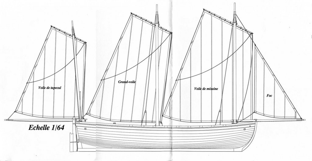
Just as a matter of interest, to show the difference from the sail plan of the Panart Armed Launch, here's the sail plan for the Chaloupe: Tony
- 124 replies
-
- 6
-
-
- longboat
- Chaloupe Armee En Guerre
- (and 1 more)
-
Thanks, Moab. A nice compliment and it's appreciated. Thanks for pointing me to the Panart Armed Launch. I hadn't thought of looking out for those builds as I hadn't realised they were rigged for sailing as well, so I'll now do so. Luckily in terms of the rigging I already have the complete set of sail and rigging plans, including the most detailed drawings of every metal and wooden component as well as of their exact placement. These plans are not part of the normal booklet (which just is of the basic boat and armament), but have to be purchased separately. Mine came for free with the plans and booklet for 'Le Rochefort' which is also produced by M. Delacroix. Interestingly the rigging plans show the boat without the cannon or its rails, although the posts for the swivel guns are included. So I have a feeling that it is expected that the armament is left out for the fully rigged boat. Tony
- 124 replies
-
- 1
-
-
- longboat
- Chaloupe Armee En Guerre
- (and 1 more)
-
Well done! Tony
-
Thanks very much for the likes everyone, and thank you aviaamator and Dirk for the kind comments. I'm still enjoying the build, mistakes and all, and glad you can see through them to that enjoyment and the fun of exploration! Tony
- 124 replies
-
- 2
-
-
- longboat
- Chaloupe Armee En Guerre
- (and 1 more)
-
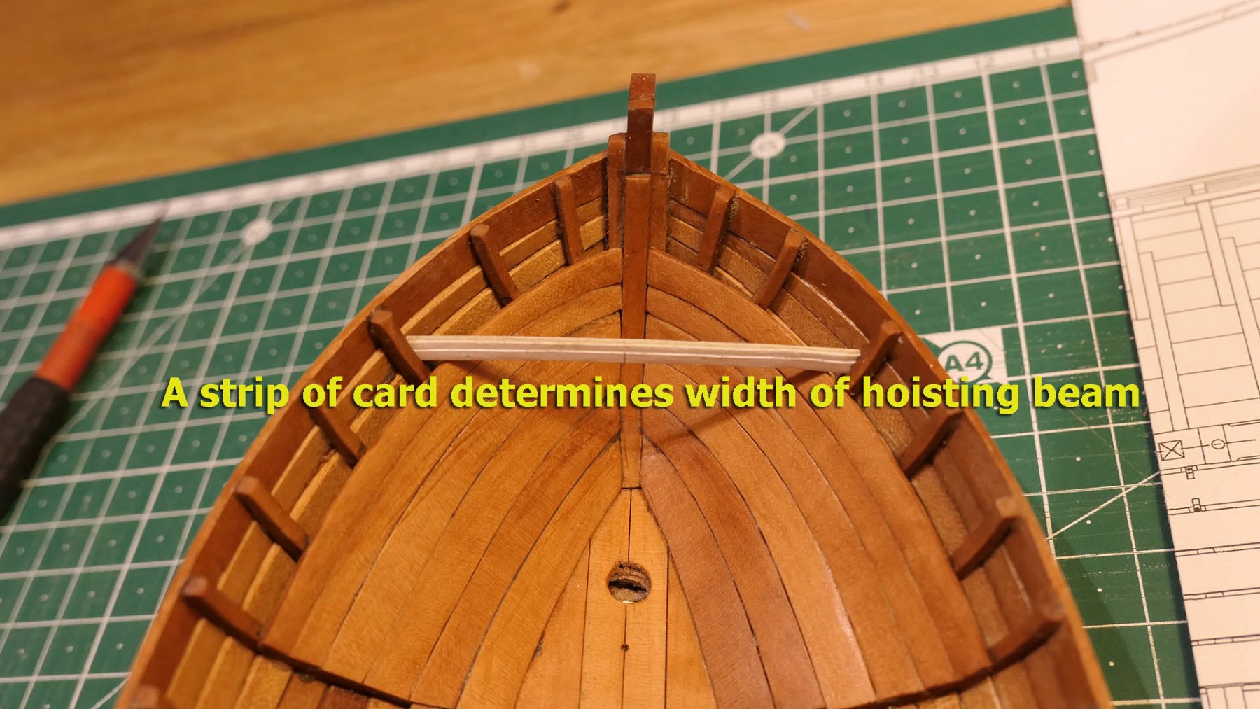
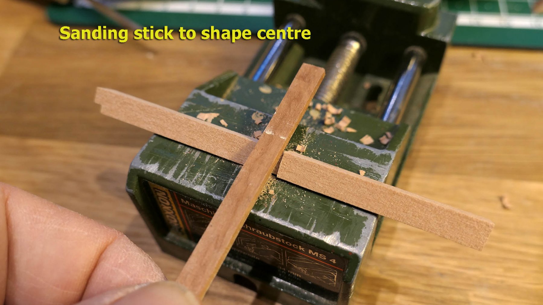
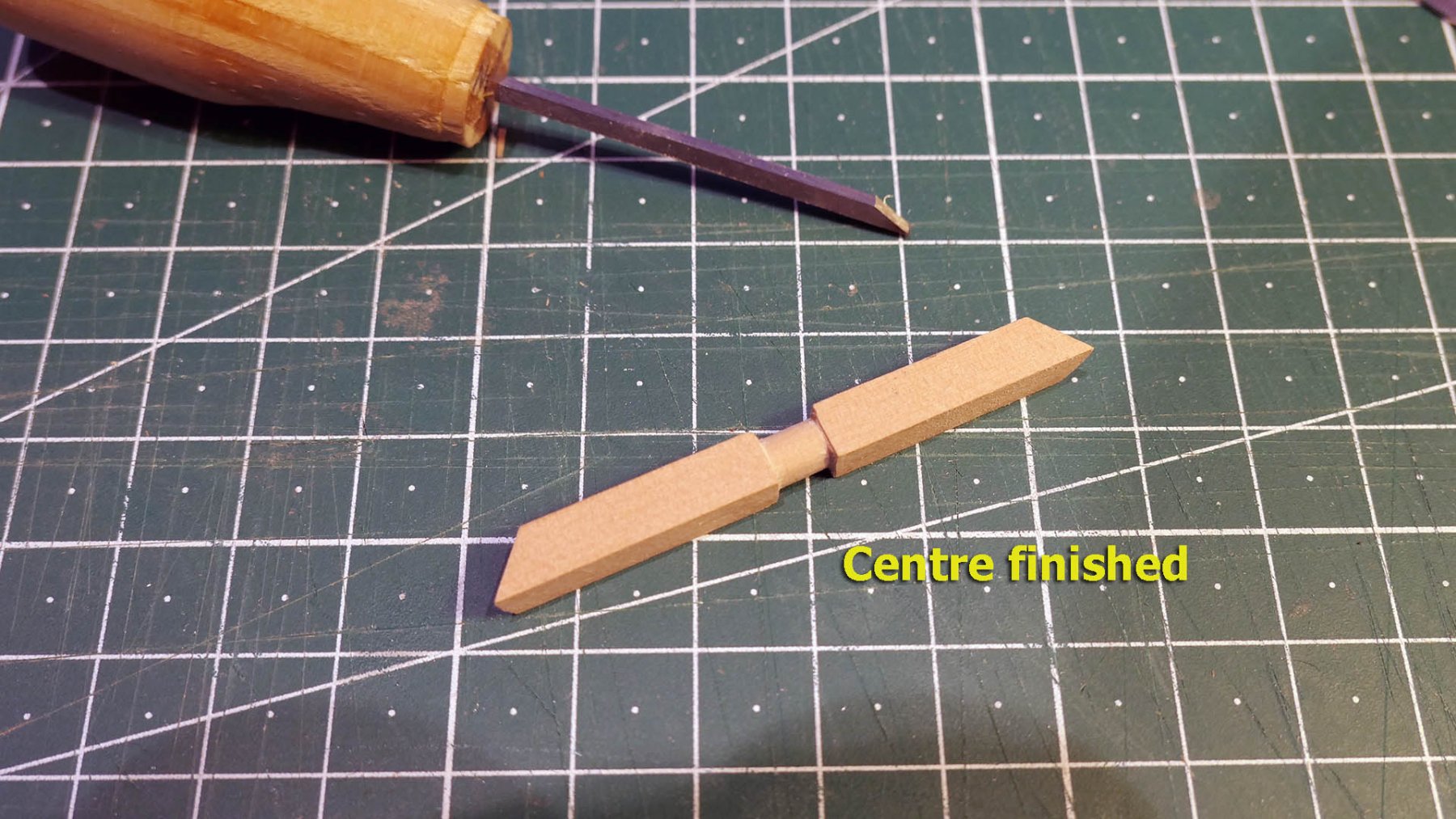
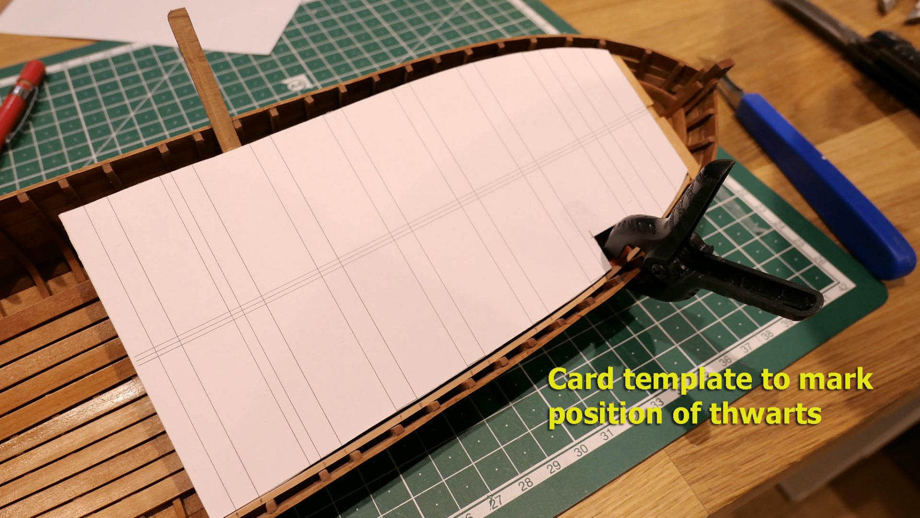
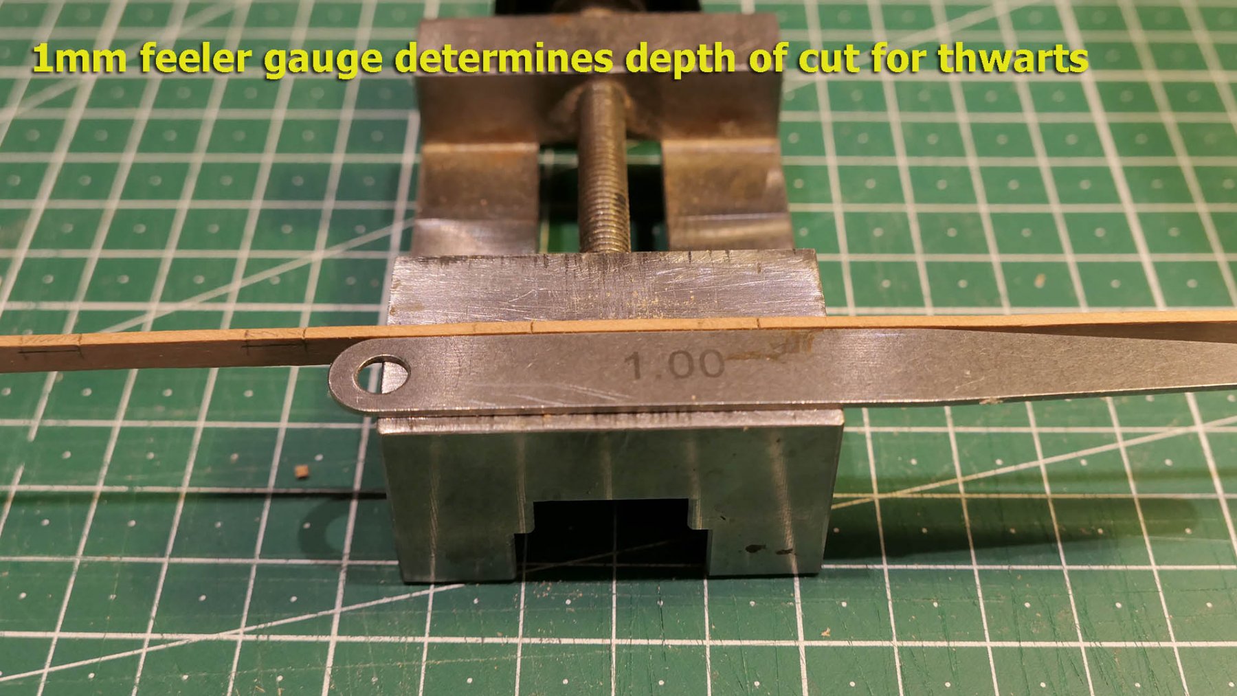
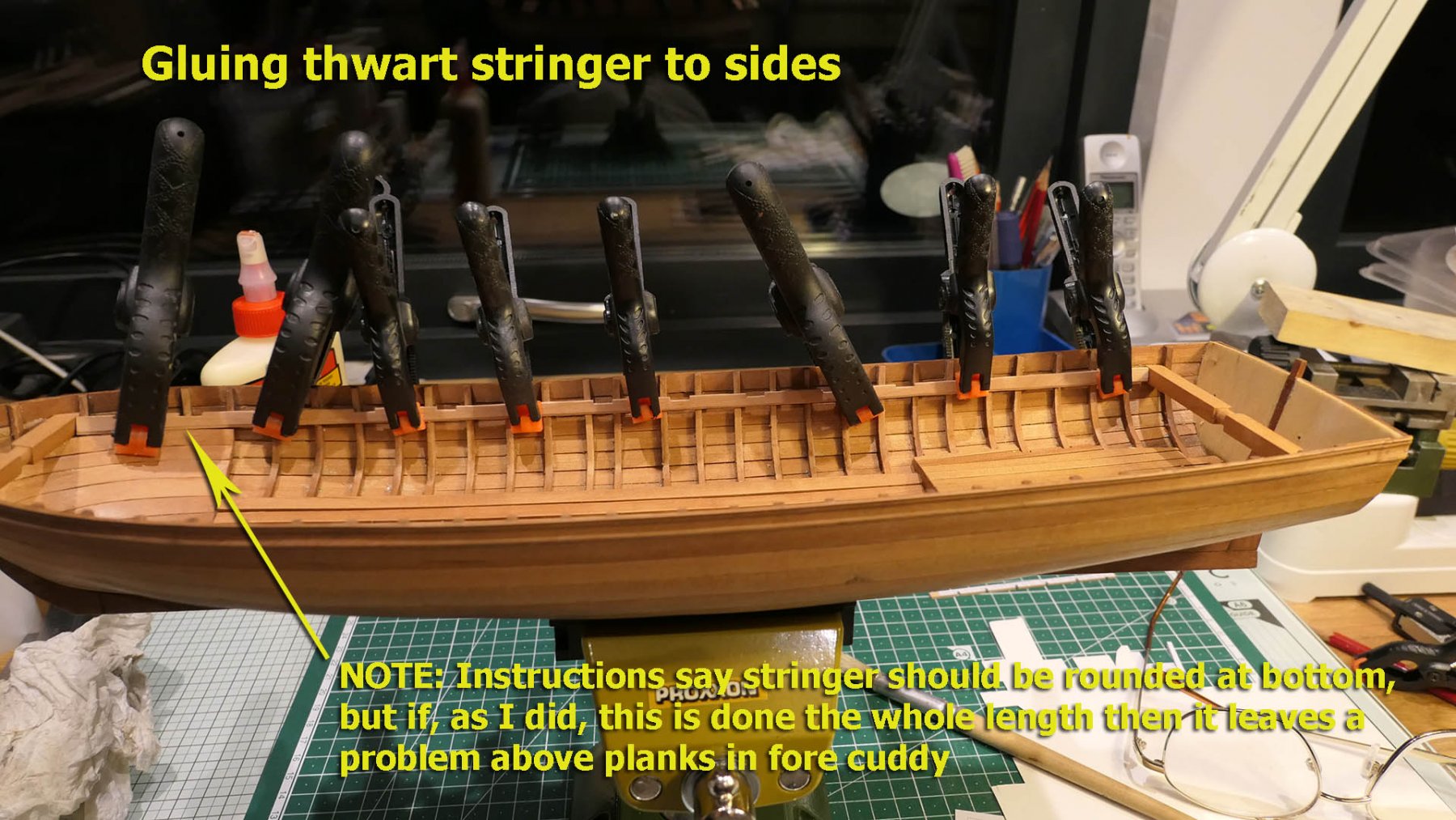
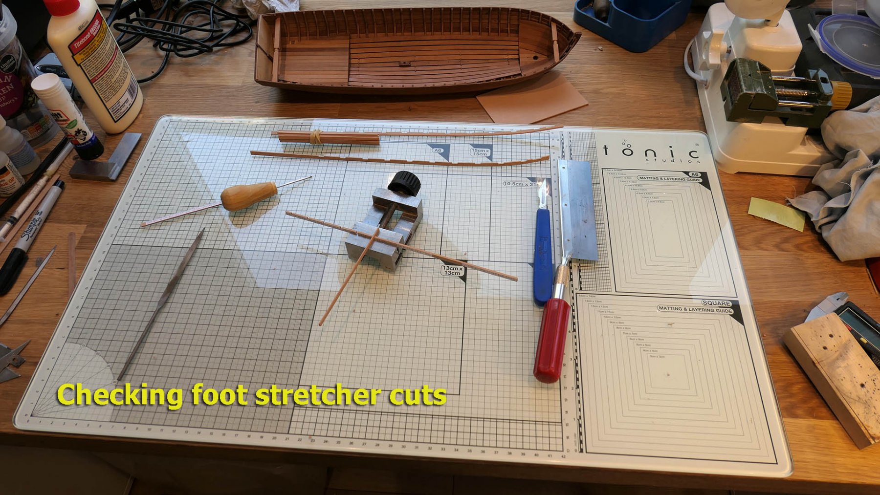
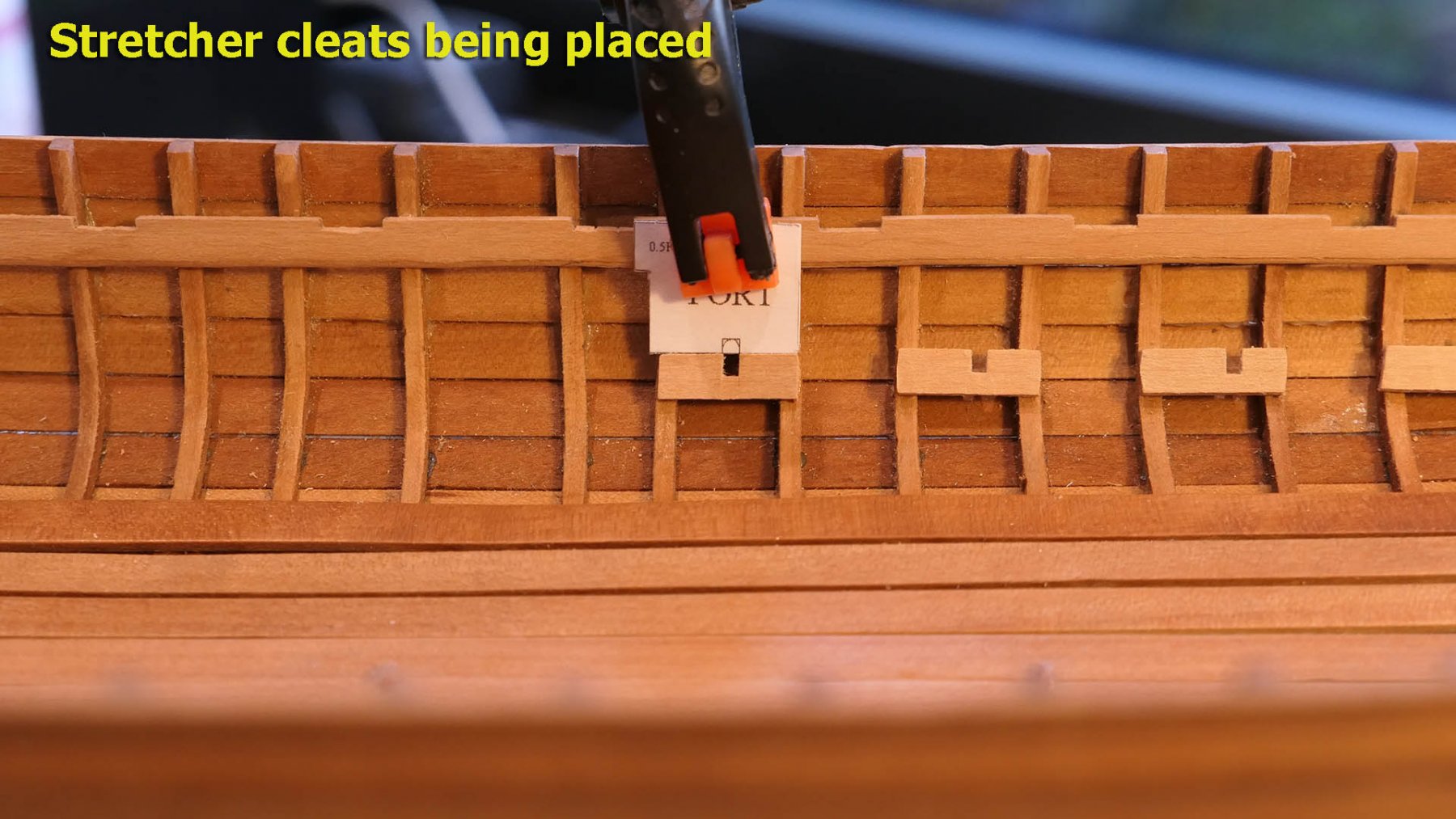
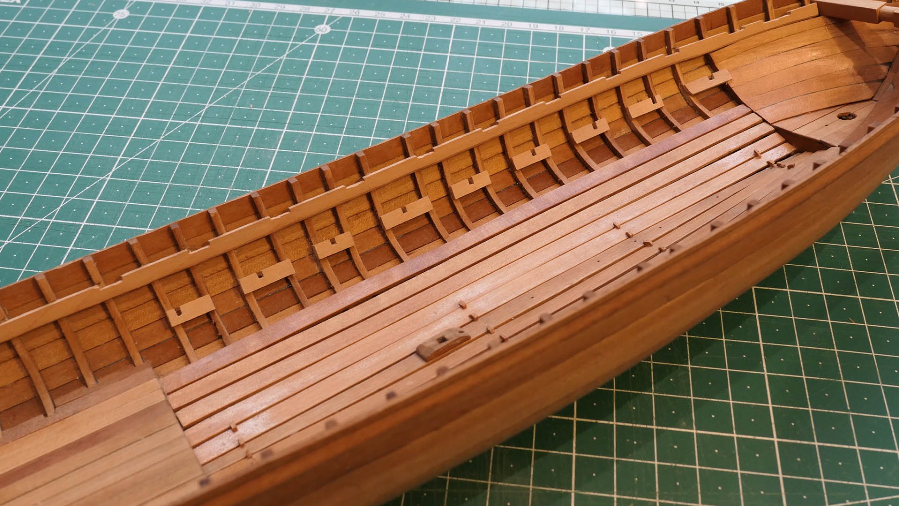
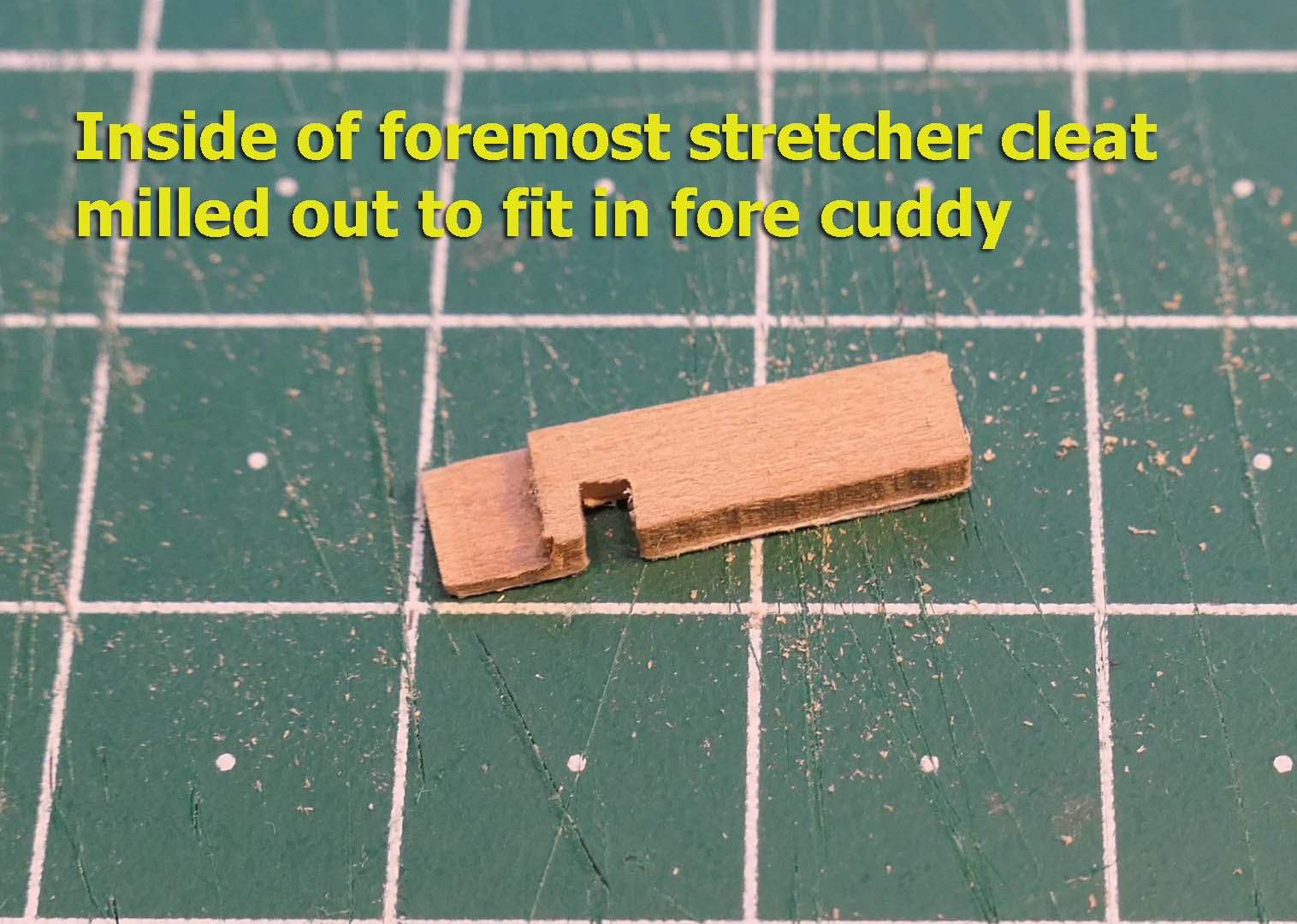
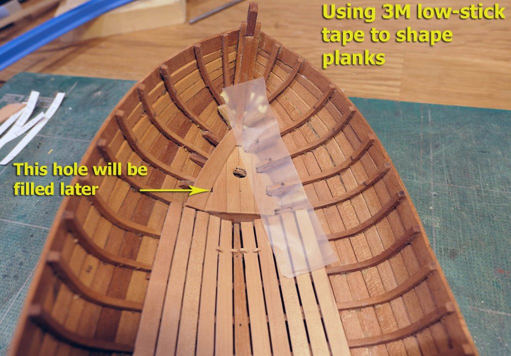
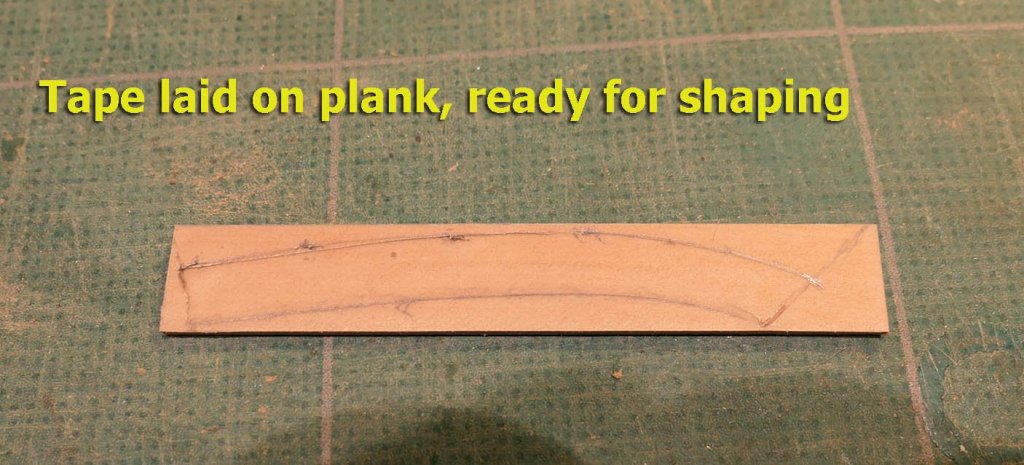
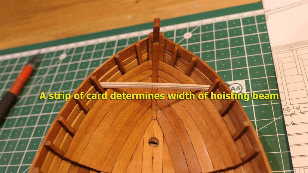
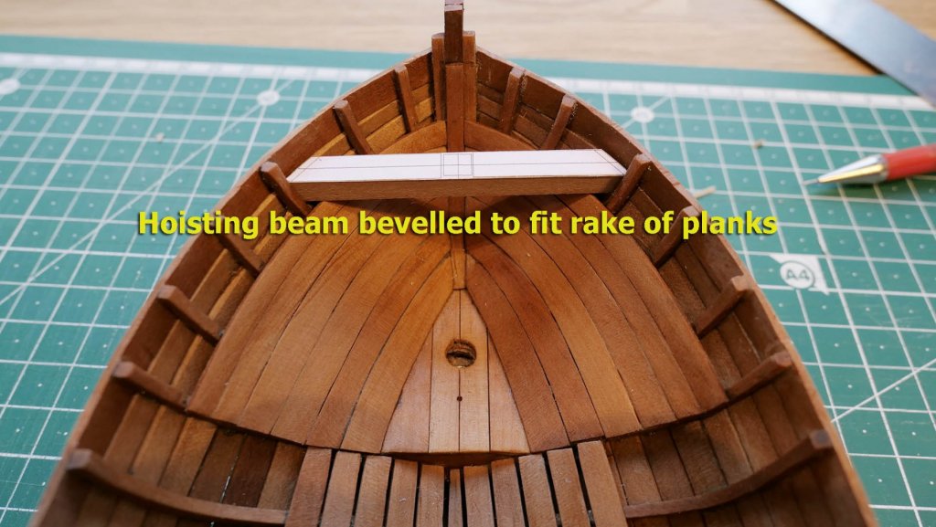
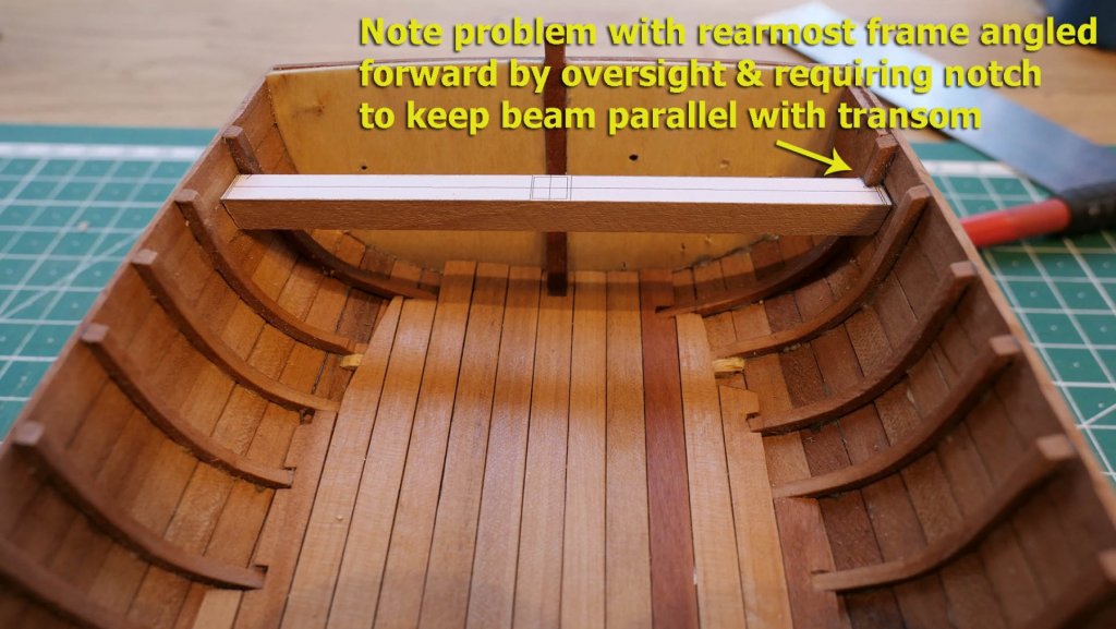
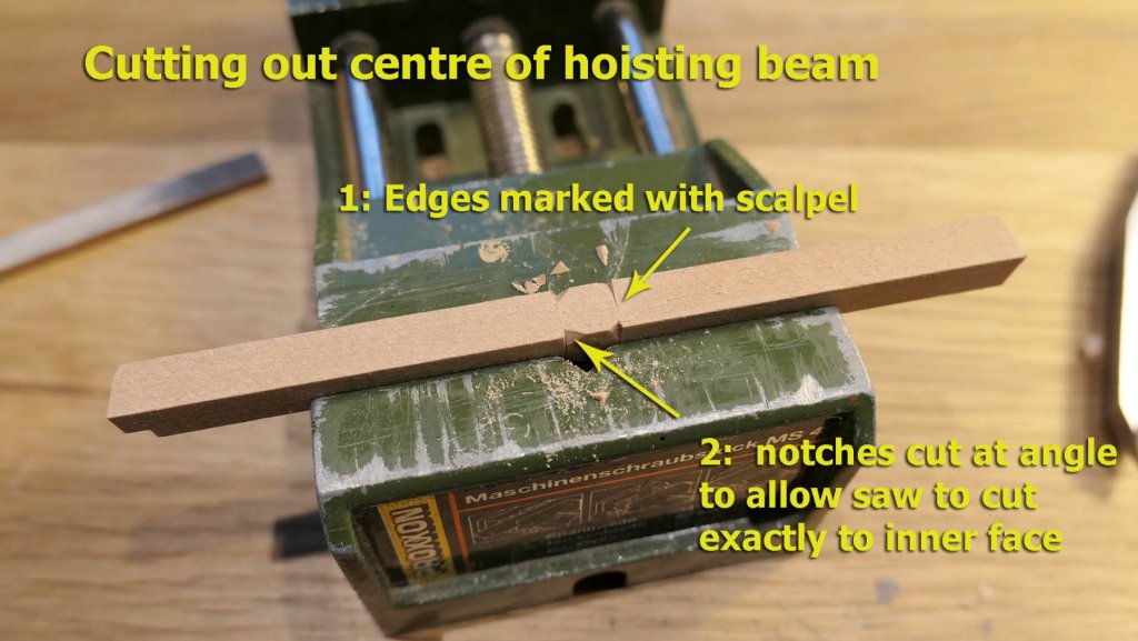
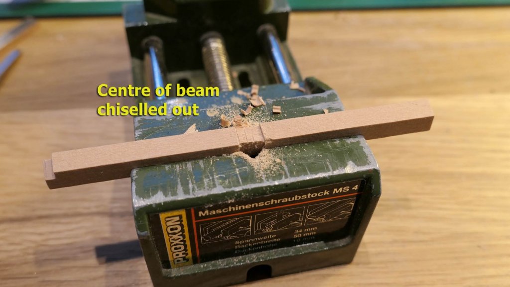
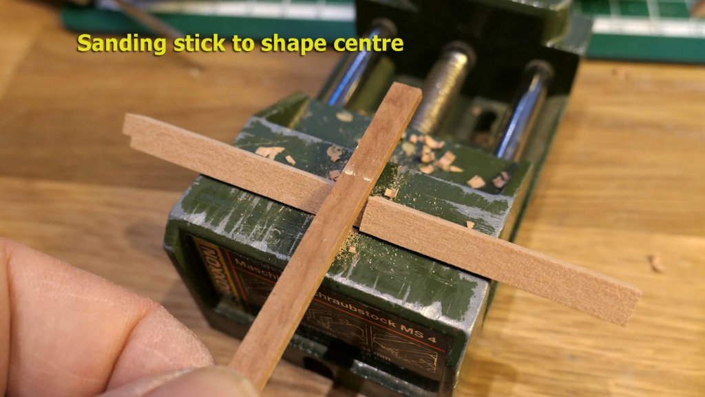
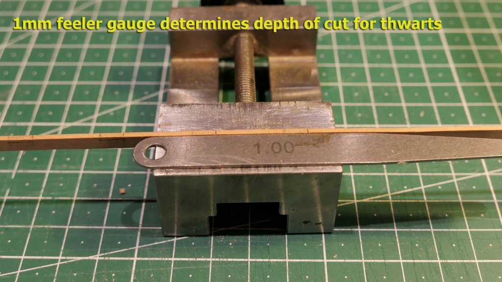
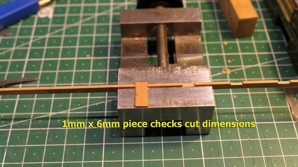
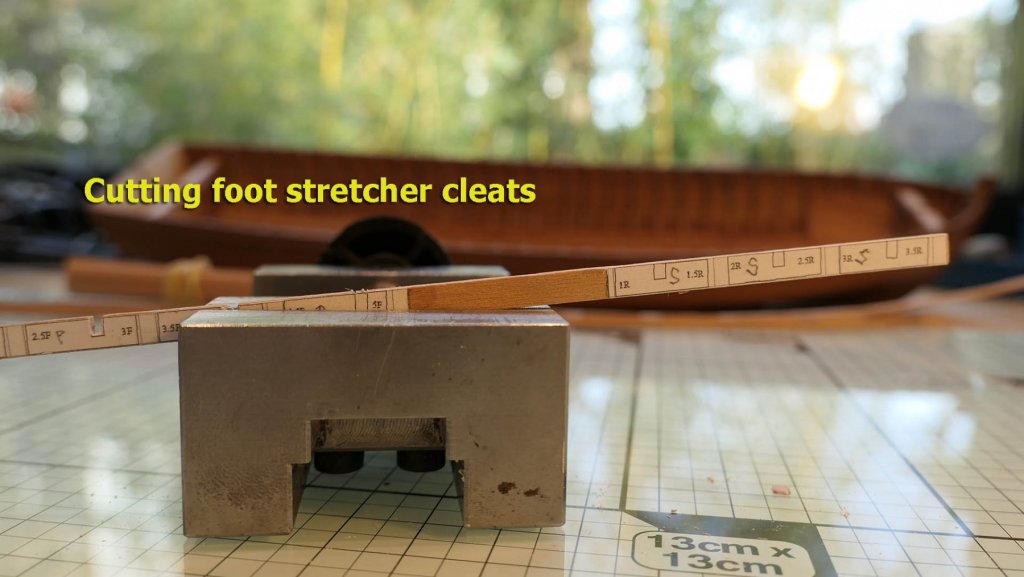
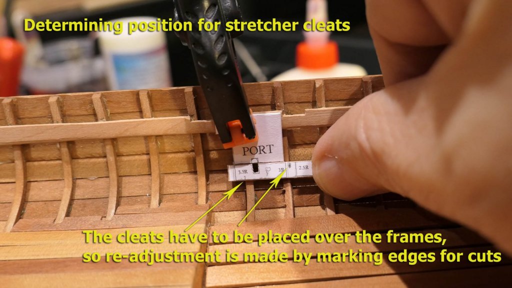
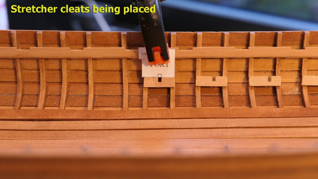
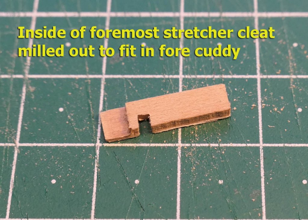
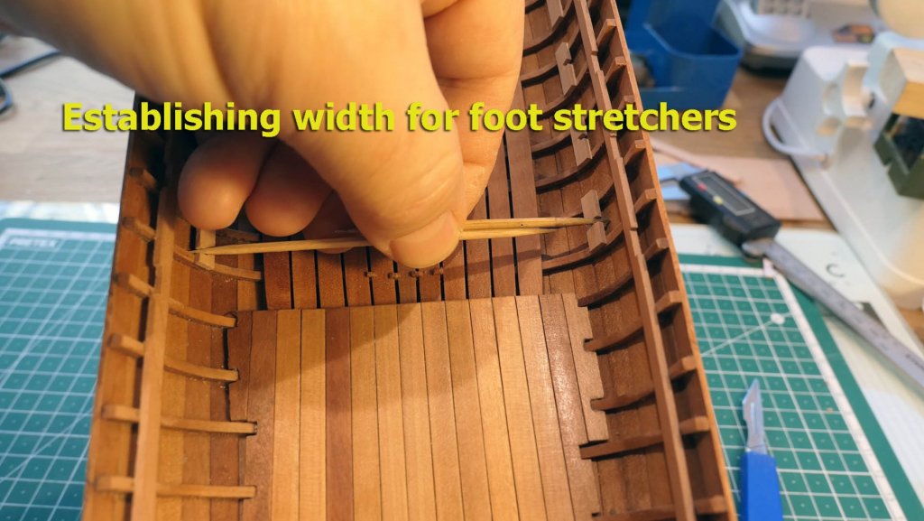
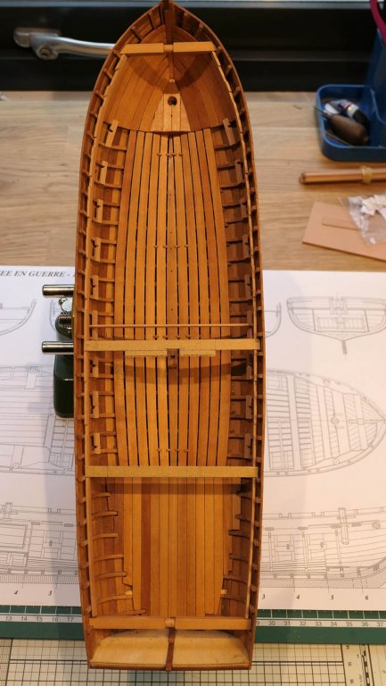
Fore cuddy and hoisting beams I used the 3M low-stick tape to determine the shaping of the planks of the fore-cuddy. These go right up to the bottom of the thwart stringer. As you’ll see, my planking here was a bit messy. Partly this was a result of my not being careful enough with ensuring the planks were bevelled to the very edges of the frames – leaving a hole between the frame and the plank. Also when it came to placing the thwart stringer, I found I had to file away the bottom of the stringer a bit in order to fit the top of the planking. I could have avoided this if I had done what I saw in Jeronimo’s build (https://modelshipworld.com/index.php?/topic/497-chaloupe-arm%C3%A9e-en-guerre-1834-by-jeronimo-finished/#comment-5561) where he built just the first three lower strakes and completed only after the stringer was in place. This would have made a neater job for me – although others seem to have managed it quite nicely without doing this. The next thing to do was to place the hoisting beams which are used for lifting the boat in and out of the water and also for handling the ship’s anchors and cables. These require careful shaping to fit the curve of the planks on either side. I determined the width first, using a piece of card which also gave me an idea of the bevelling needed. When it came to the rear hoist beam, I discovered that the last frame on the port side (the one sticking to the keel without an accompanying floor) had come out of vertical and so I had to cut a notch from the beam to keep it parallel with the stern. This brought home the need to double check the verticality of all the frames before planking. Still, this is a learning exercise! I then cut out the central rounded portion of the beams using a combination of scalpel (for marking), saw, chisel and sanding stick as follows: Thwarts I then made a template for positioning the thwarts, and used it on the positioned (but as yet unglued) stringer. I used a 1mm feeler gauge to determine the depths of the cut-outs on the stringer for the thwarts (which are 2mm high and stand proud of the stringer). This depth was checked using a small offcut of the correct dimensions. I glued the thwart stringers into place. Unfortunately I rounded the entire bottom length of the starboard stringer (as advised in the instructions) which made an awkward/ugly fit on top of the fore cuddy planks. I was too lazy to unglue it all and shape another long piece and decided to live with it as a constant reminder of the need to think ahead! Foot stretchers I used a template to cut the slots for the foot stretcher cleats. I then checked the dimensions of the slots with a foot stretcher. You’ll see a tempered glass cutting mat in the next photo. I’ve been trying it out in preparedness for some paper modelling I’ll be doing while recovering from surgery over the coming three months as I’ll not be allowed to lift or strain chest muscles. I then used another template to position the cleats for the foot stretchers. The plans, of course, are drawn in the expectation that the frame positions end up precisely as portrayed . Unfortunately it seems my skills in ensuring the same positions were not quite up to the mark and so I had to change the dimensions of the cleats in order to fit exactly over their respective frames. I have to admit I quite enjoy trying to compensate for my various mistakes. Again it’s all part of learning! The same template was then used to position the cut cleats. You’ll note that the foremost cleat lies on the edge of the fore cuddy. In order to fit it nicely, I therefore milled out its inside edge. The width of each stretcher was then determined using the old method of sliding sticks. Finally I checked the orientation with regard to the stern by measuring and placing card thwarts and a stretcher. So I am now deliberating whether I will arm the longboat with its cannon and swivel guns. I am not interested in building ships of war, more in developing skills in modelling and working on coastal boats. Also I am thinking about masting and rigging the boat. I can’t see how the sails would work with the huge cannon in the middle of the boat. So I am studying the sail plans and will make up my mind over the next week or so. In the meantime I also have to think how to make the thwart supports and some of the wood attachments and ironwork that goes onto the hull and thwarts (mast holders, cleats, rings etc.). All in all, it may therefore be some time before I can continue this log. Tony


- 124 replies
-
- 23
-
-
- longboat
- Chaloupe Armee En Guerre
- (and 1 more)
-
Admiralty model query
tkay11 replied to iMack's topic in Building, Framing, Planking and plating a ships hull and deck
One interesting question is when did the contrast start between 'kits' and a rather romanticised notion of 'scratch building'? There have been many discussions about the contrast between 'scratch' and 'kit' building on this forum over the years and you might like to search for them to see the sometimes vigorous and passionate arguments. The current thread repeats many of them. Until very recently 'scratch building' was the norm for hobbyists and amateur modellers. Harold Underhill produced his book on Plank on Frame Models in 1958, and this was then aimed at what was probably a thriving market. Before that there is a centuries-long history of making model boats either from plans or from memory. Even then some people would buy parts that they did not want to make, or assemble (string, wire, nails, glue, varnish, pre-cut wood planks) and 'kits' are just a continuation of this idea. The sharp distinction is unclear to me, the spectrum is not. There is also the question of the number of different skills and the time required to obtain them, as has been raised already in this discussion. I think I read that Admiralty models were not built only by one person, but by teams of craftsmen and apprentices -- a number of different skills would be required (someone more knowledgeable might like to comment on this: for example was only one person responsible for drafting the plans, lofting, and making all the different parts?). Another spectrum: the history of model-making includes the full range of those who try to create replicas at a lower scale (and which can never be true replicas as not every detail can be exactly miniaturised, sails being one example) to those who just build something fanciful or attractive to themselves for other reasons. In Egypt I saw some wonderful models made 4,000 years ago. People even argue about the accuracy of full-size replicas, especially when propellers are added. Just now I am 'scratch-building' a small gaff-rigged 'cutter' from a walnut shell for the grand-children (although there won't be a build log on this forum for it). And another: there is an enormous number of reasons that people have when they build models. Is it for yourself, the enjoyment of others, to sell, or to impress? Is it to sail, to miniaturise, to challenge, to occupy your mind, to get away from problems, to create with your hands, to learn, or simply to enjoy your own creations? So, Bob, as suggested by others in this thread, don't be put off by one particular view of 'true' scratch building (unless you really do want to mimic the original work of the modellers who worked on the Admiralty models -- and even amongst them there were quite a few differences, so you'd probably have to choose a particular model and make the tools and materials they used). There is no such thing. Just think what you'd like to achieve and then start to practice with the tools you have at hand, some plans and a good read of the variety of builds available on this forum. You might enjoy Harold Underhill's 2-volume set which you can buy used from Amazon for £20, or new from Brown, Son and Ferguson for £50. He just worked with a few basic tools and an old card table. Underhill also produced hundreds of plans of boats of very different types which are still available cheaply from Brown, Son and Ferguson -- including the small coastal craft which have been mentioned in this thread. And never be ashamed of your efforts when comparing them to the skills of others. Don't forget other people had to start somewhere and gradually learn the skills they continue to master. Just determine the compromises with which you are comfortable, since whatever the model you will have to accept compromises at the altar of learning. In my own model-making I try to be as objective as possible about my strengths and weaknesses, and learn from the experience of others to improve the weaknesses. That is the great strength of logging a build on this forum. There will be lots of general encouragement (which is always welcome and boosts your confidence), and there will also be people providing critical comment or advice. Should you ever ask a question you will always get a host of replies. You will also appreciate very quickly that there are numerous different approaches to whatever problem you face, so again you can make your own choices as to the type of answer you prefer. Take heart, read lots of build logs, dive in and enjoy! Tony -
You may like to obtain Harold Underhill's two volumes called "Plank on Frame Models and Scale Masting & Rigging" first published in 1958. These are available used as a set on Amazon UK at the moment for £20 (https://www.amazon.co.uk/Plank-Models-Masting-Rigging-Volumes/dp/B00161MO38), or for £45 new from Brown, Son & Ferguson (https://www.skipper.co.uk/catalogue/books/page). These books show how to interpret plans and build using a minimum of equipment and space. They are regarded as a classic introduction to model ship building. He encourages the use of pinning as well as gluing, but some suggest nowadays that this may no longer be necessary for all the joints in a boat as modern glues are very strong. You can make your own mind up about that. Tony
-
It's an interesting thought that not so long ago (perhaps up till half way through the last century) a lot of the books for beginners were about scratch building. There are still quite a few books from that era in print as well as being downloadable, so you might want to research those. In fact there are files available in the download section of this forum that will give good advice on starting to scratch build. Plans are plentiful and not very expensive for good ones. The only thing I'd recommend if you're going to do scratch building is to get a CAD programme. Some are free. The one I use is TurboCAD which you can pick up from about £20 for earlier versions. But it's far from necessary. It just allows you to re-scale plans easily and develop templates for your own parts. Even basic photo-editing programmes have much the same function, and if you work with Linux then there's excellent free software on that platform. My own experience was that I started with a kit (of the Sherbourne) but very quickly went to making my own parts. In fact almost the only part I built from the kit was the basic hull. Looking back on it all, it wouldn't have been that hard to build it all from just the plans. As a result, after completing the Sherbourne, I went to building the Triton cross section (the plans for which are available for free on this forum) and because there are so many other build logs for this there is plentiful experience and advice to help you build it. I'm now not at all wary of scratch building (although of course my skills are not at all great) and in fact I very much enjoy being able to create and re-create parts as well as figure out how to interpret plans. A particular disadvantage of many kits is that the wood they supply is variable in quality. When you build from scratch your wood supply is up to you. Finally, if you're worried about building intricate and small parts, there's quite a lot of such parts available as photo-etch or manufactured from model suppliers. I wish you well in your endeavour! Tony
-
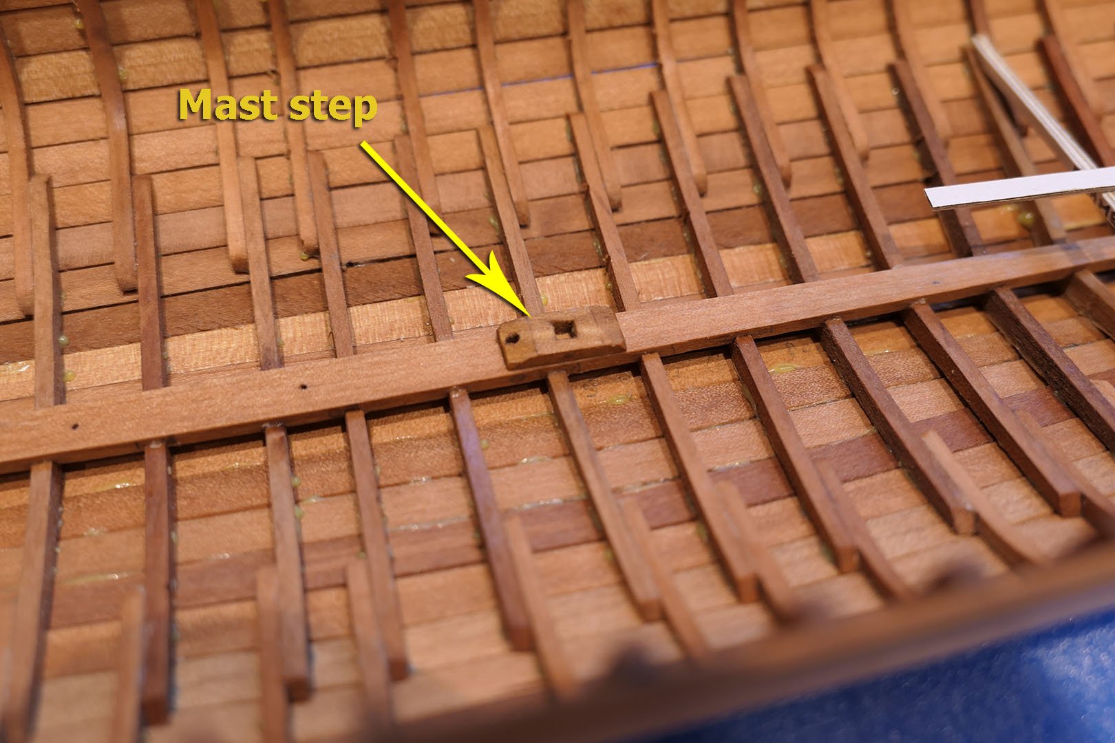
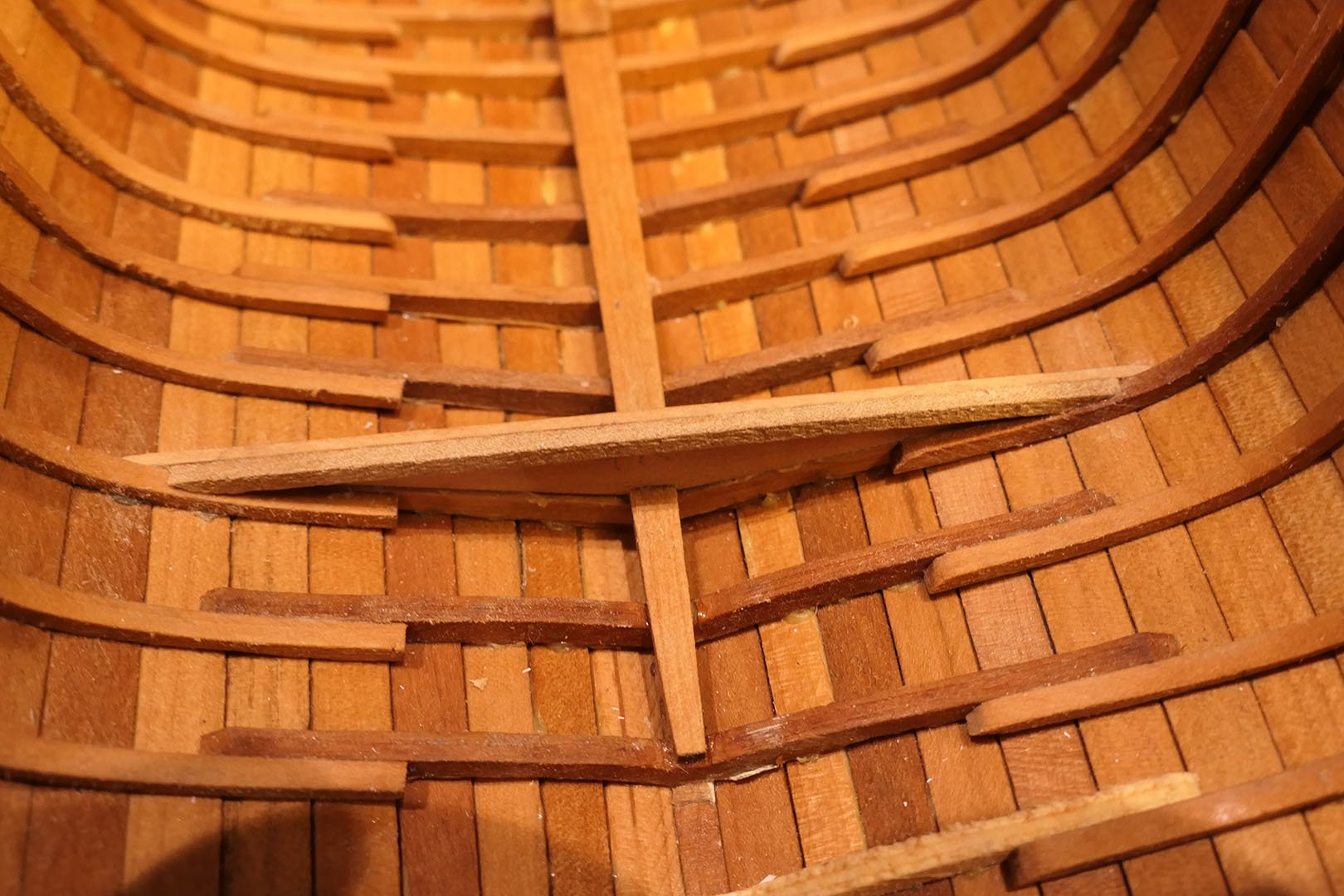
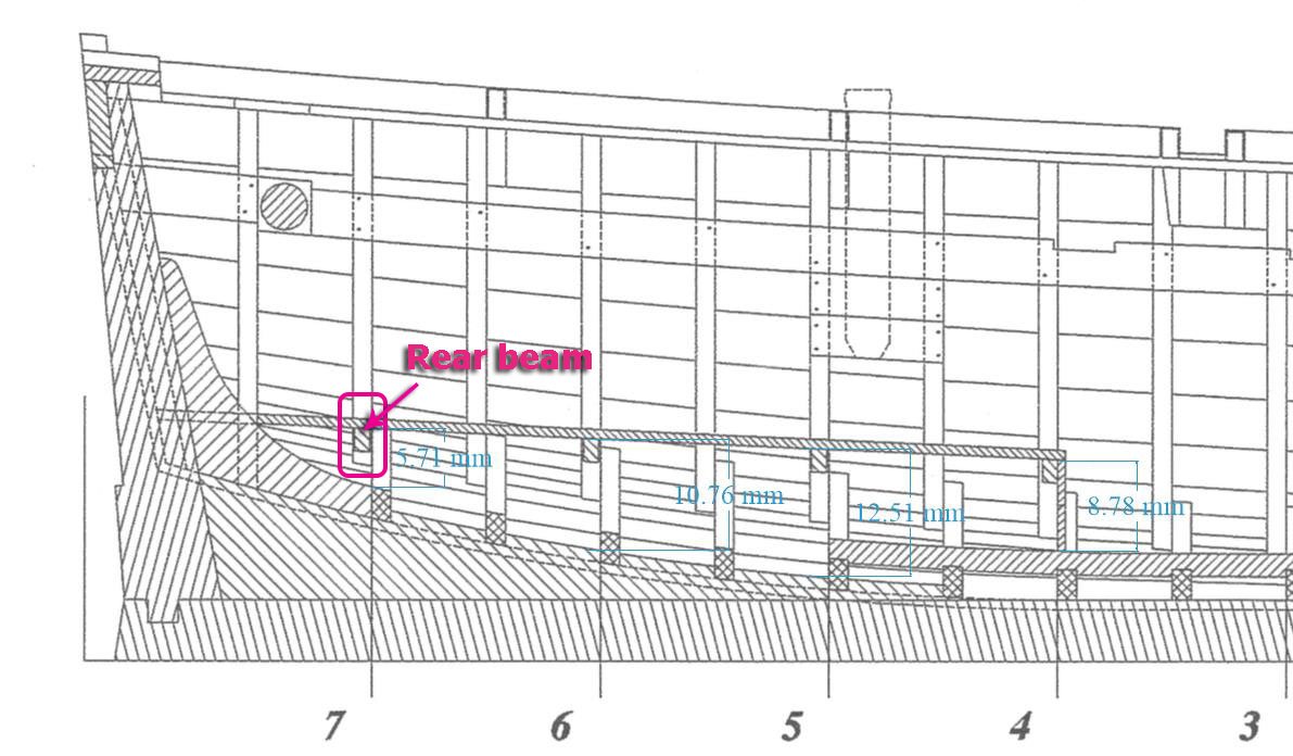
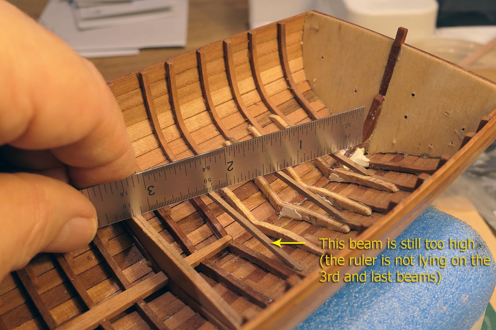
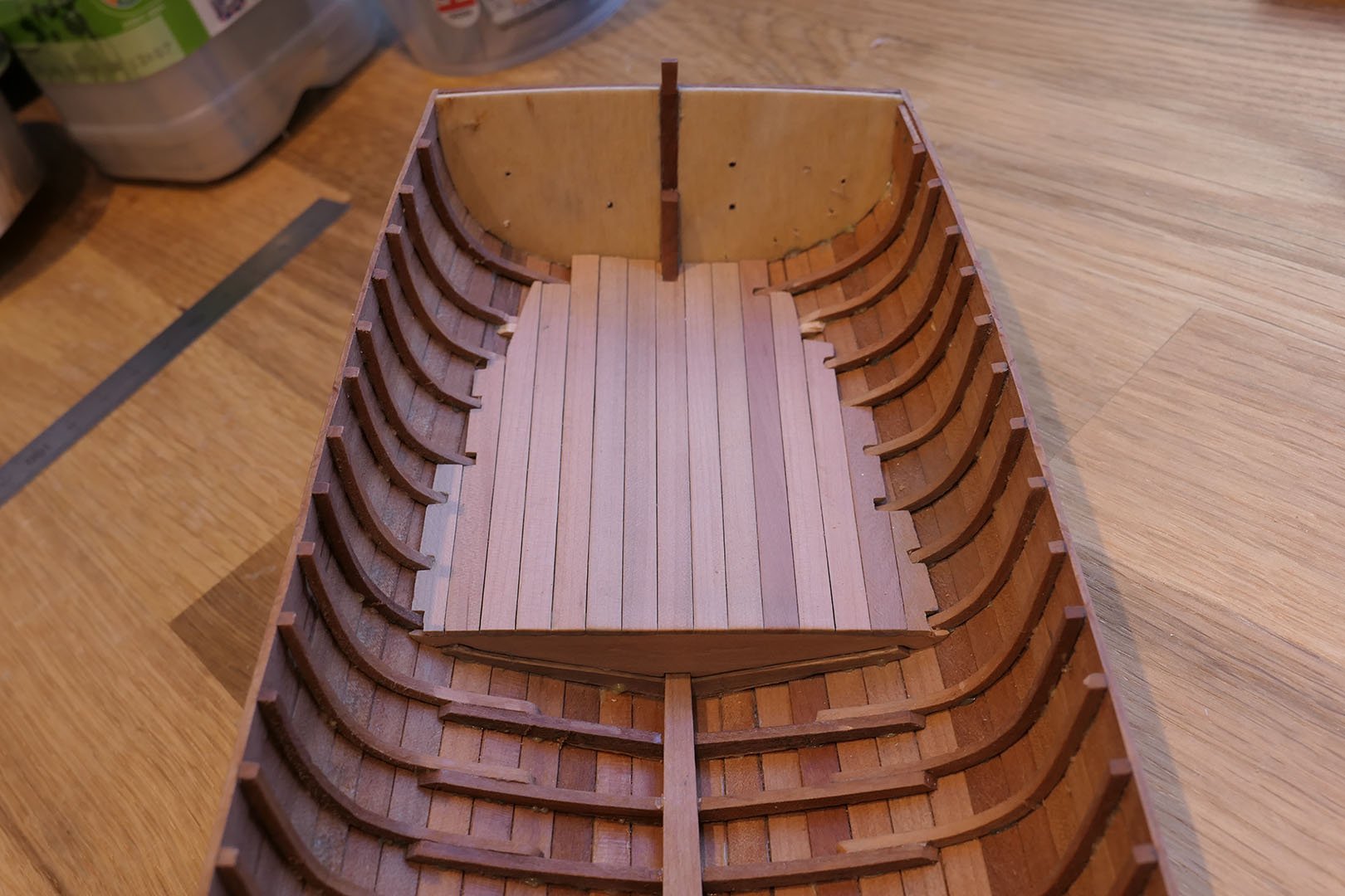
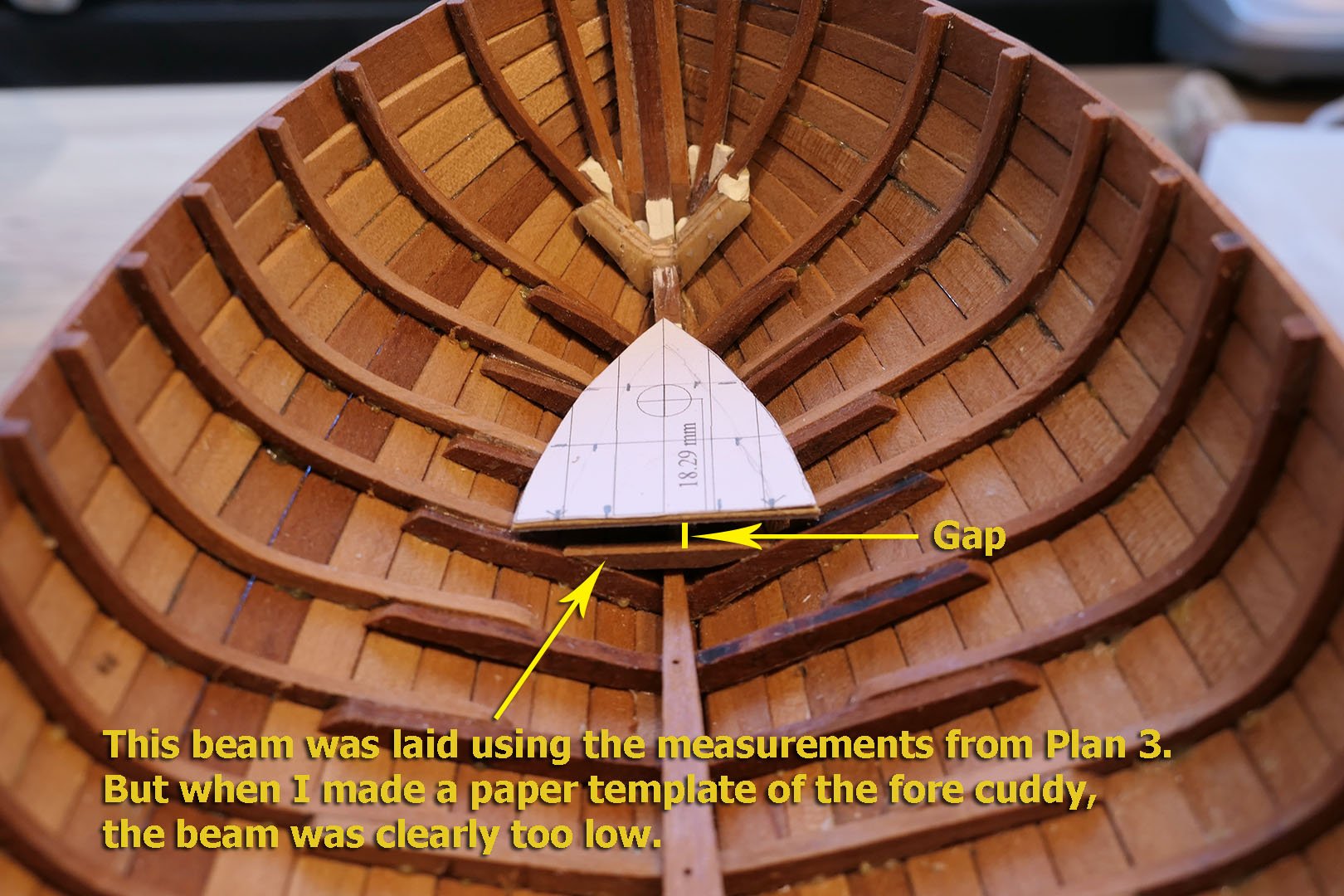
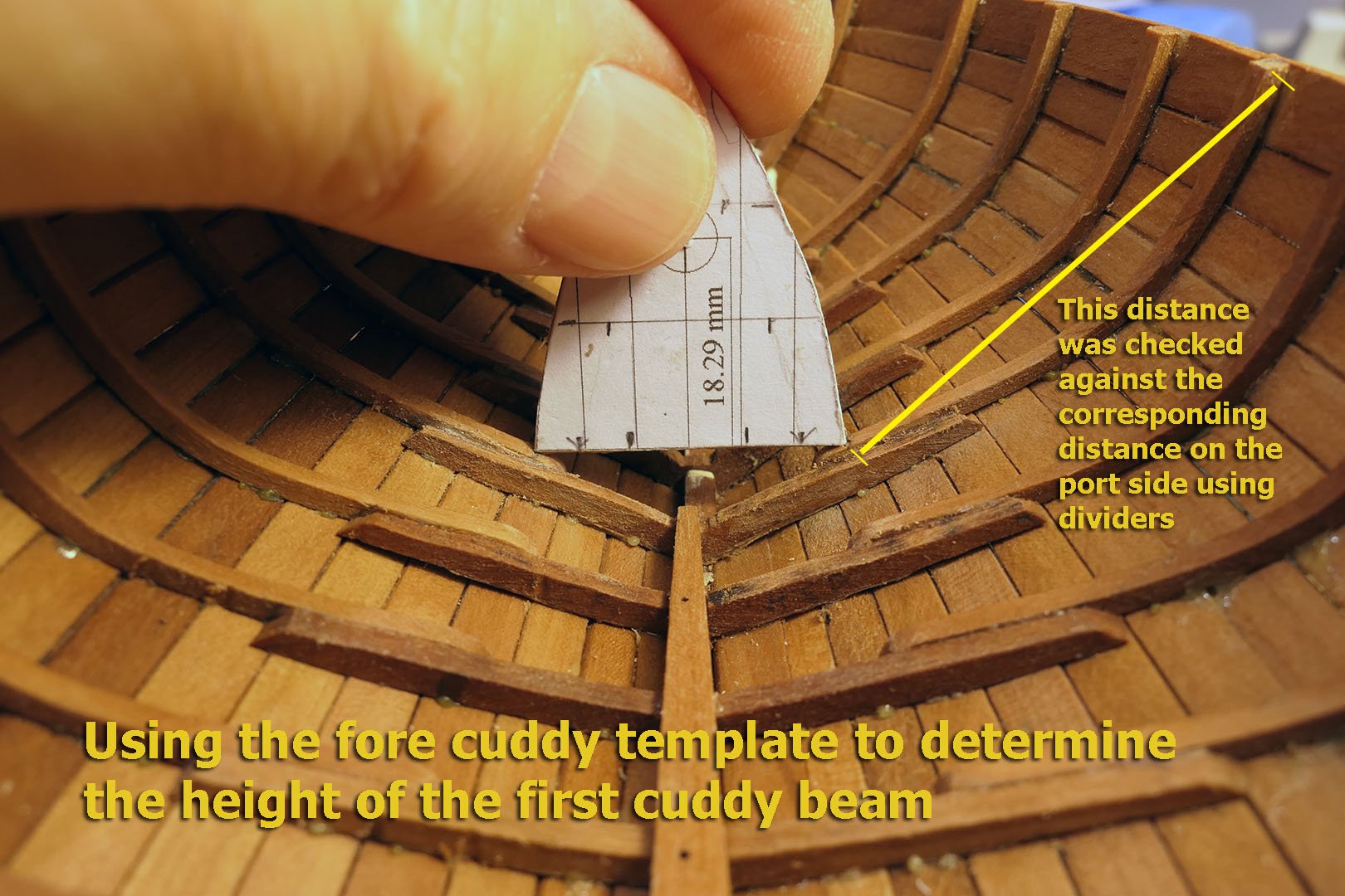
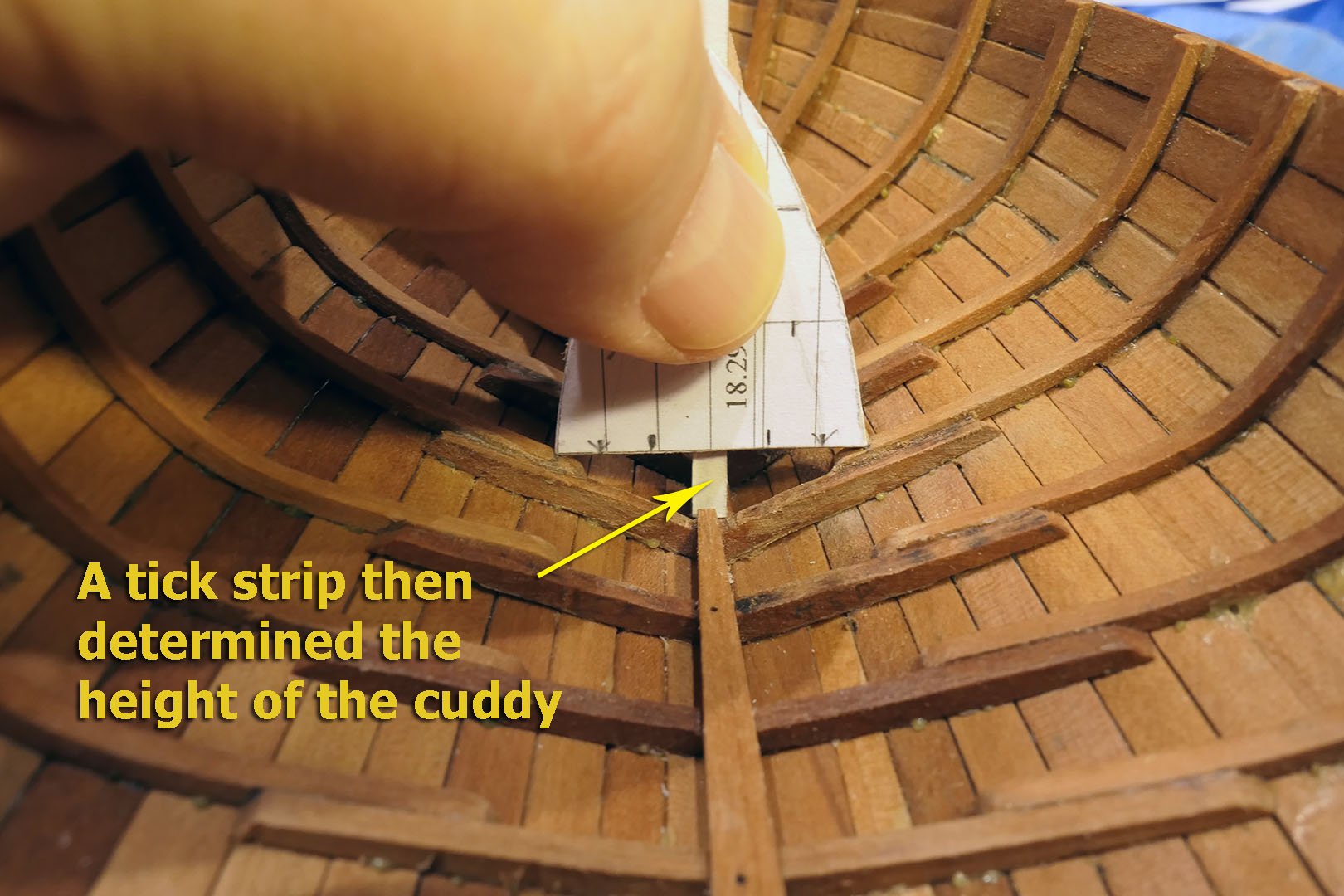
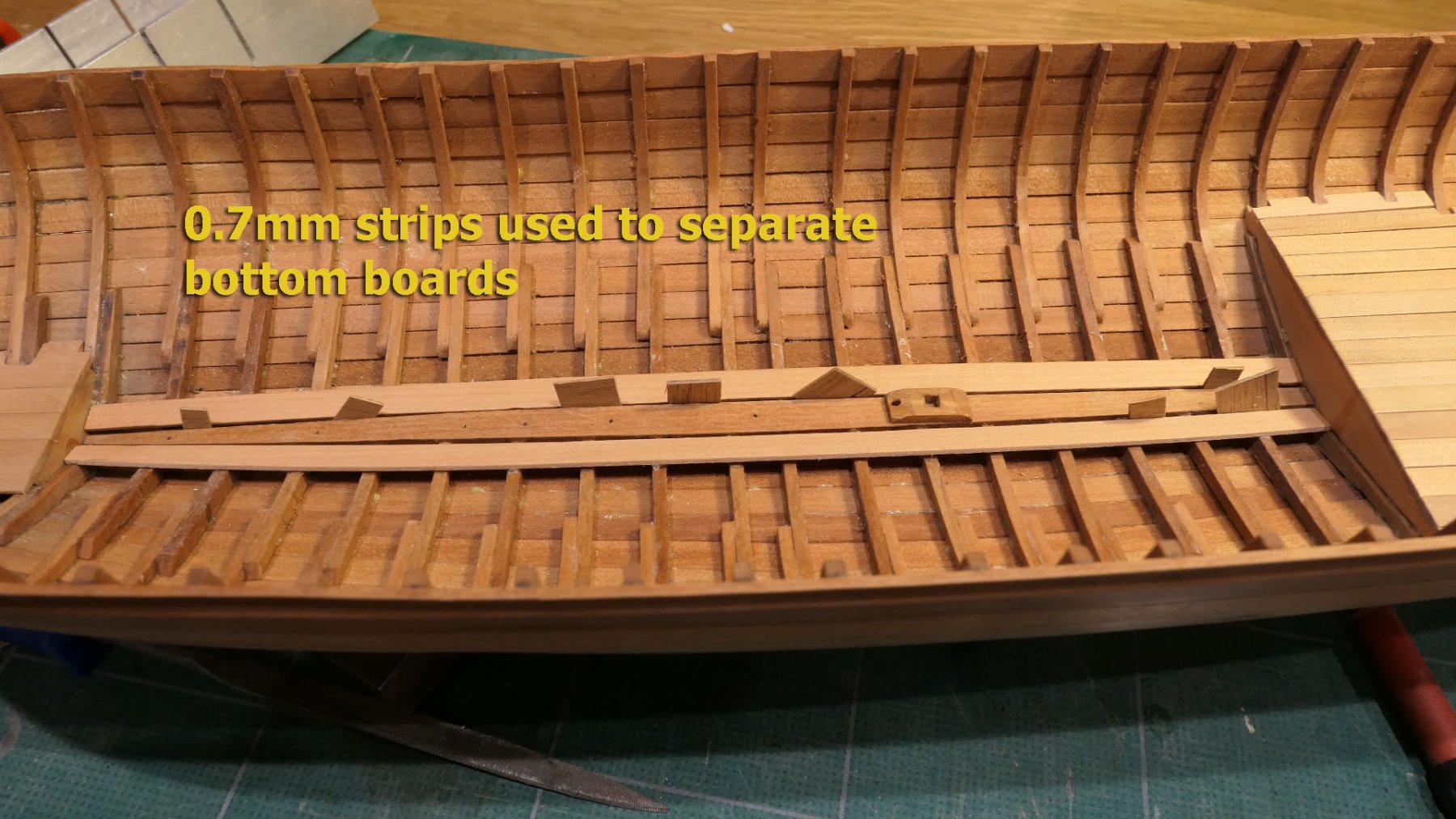
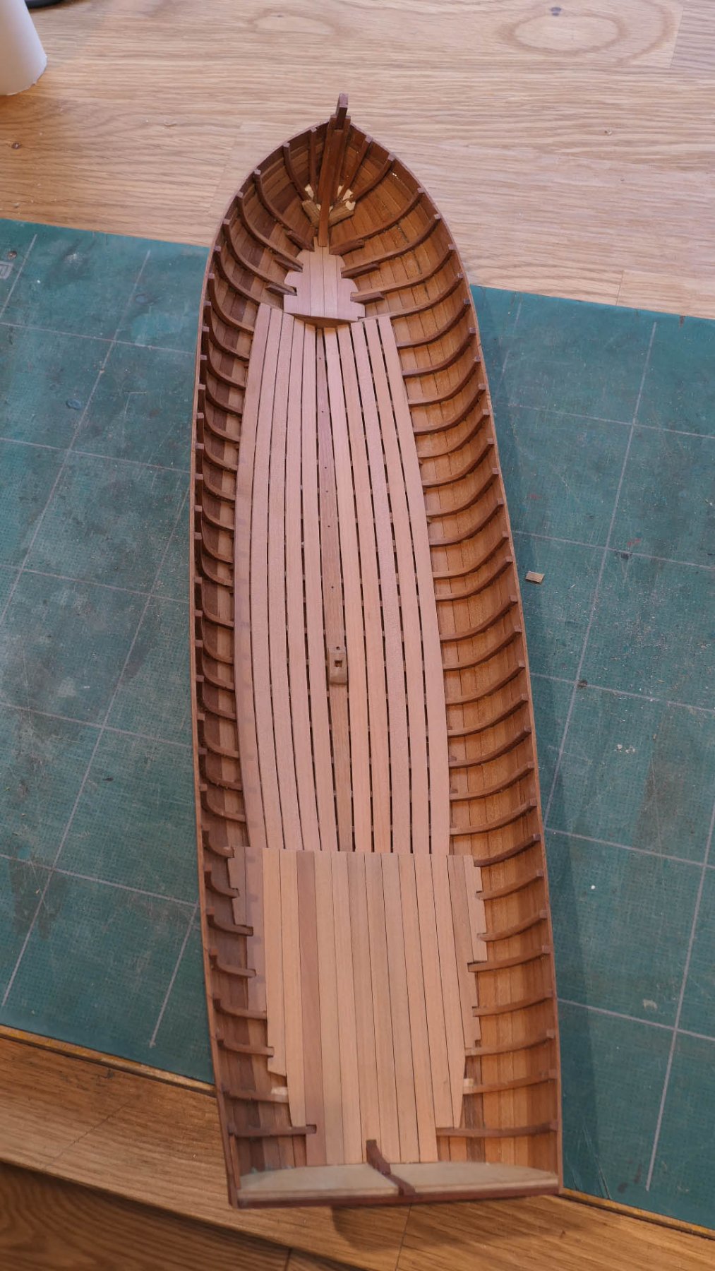
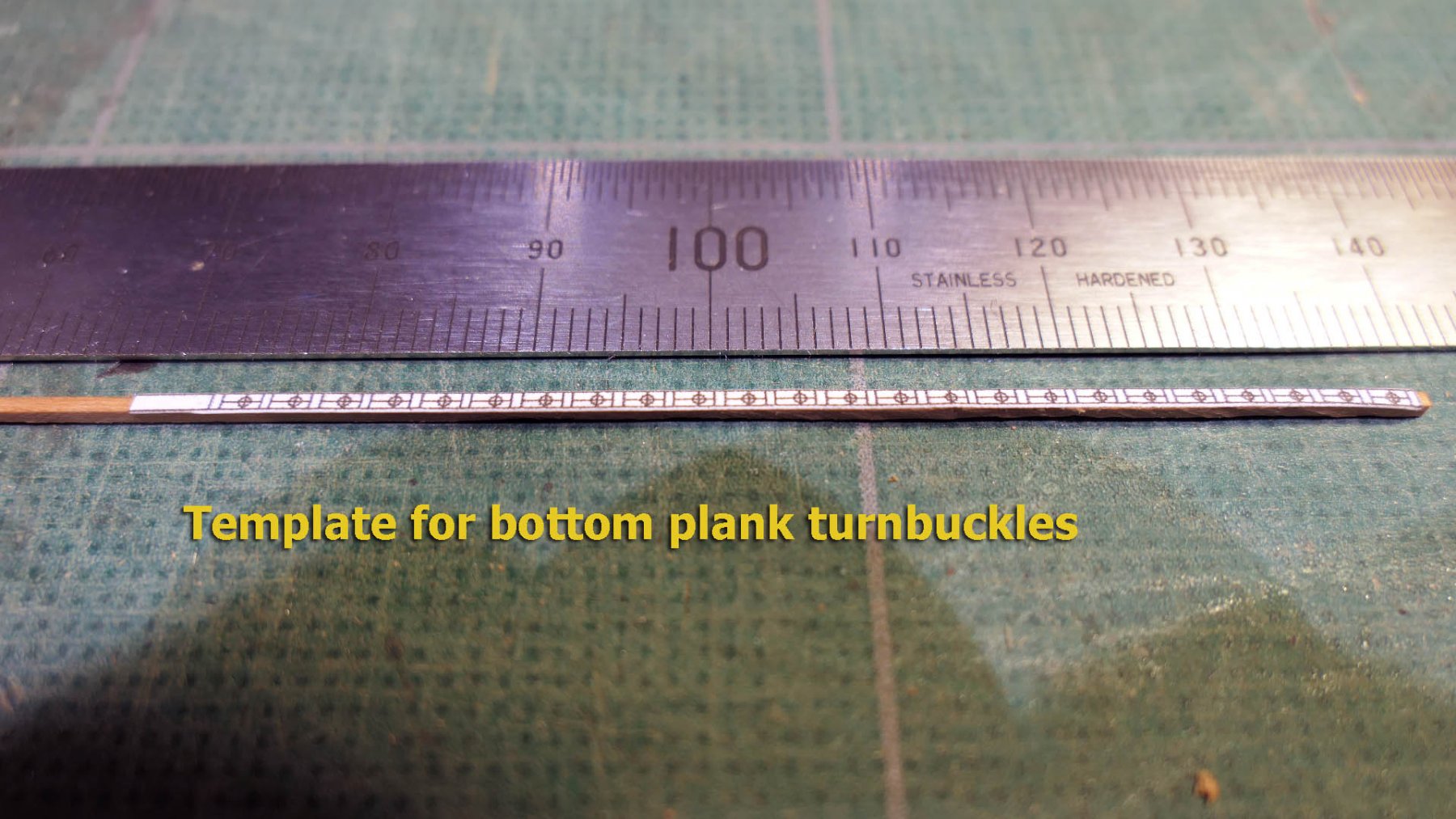
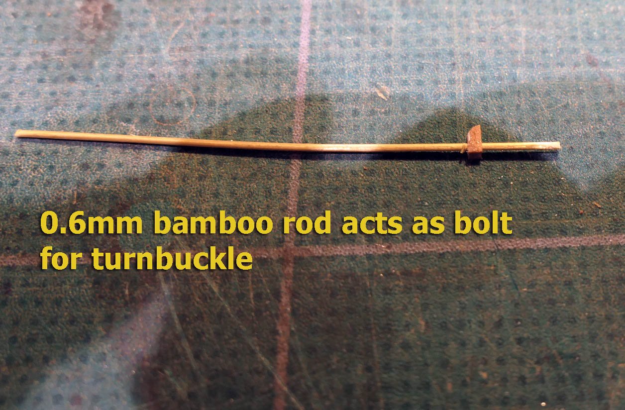
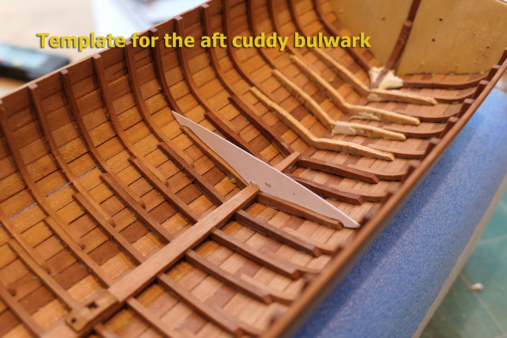
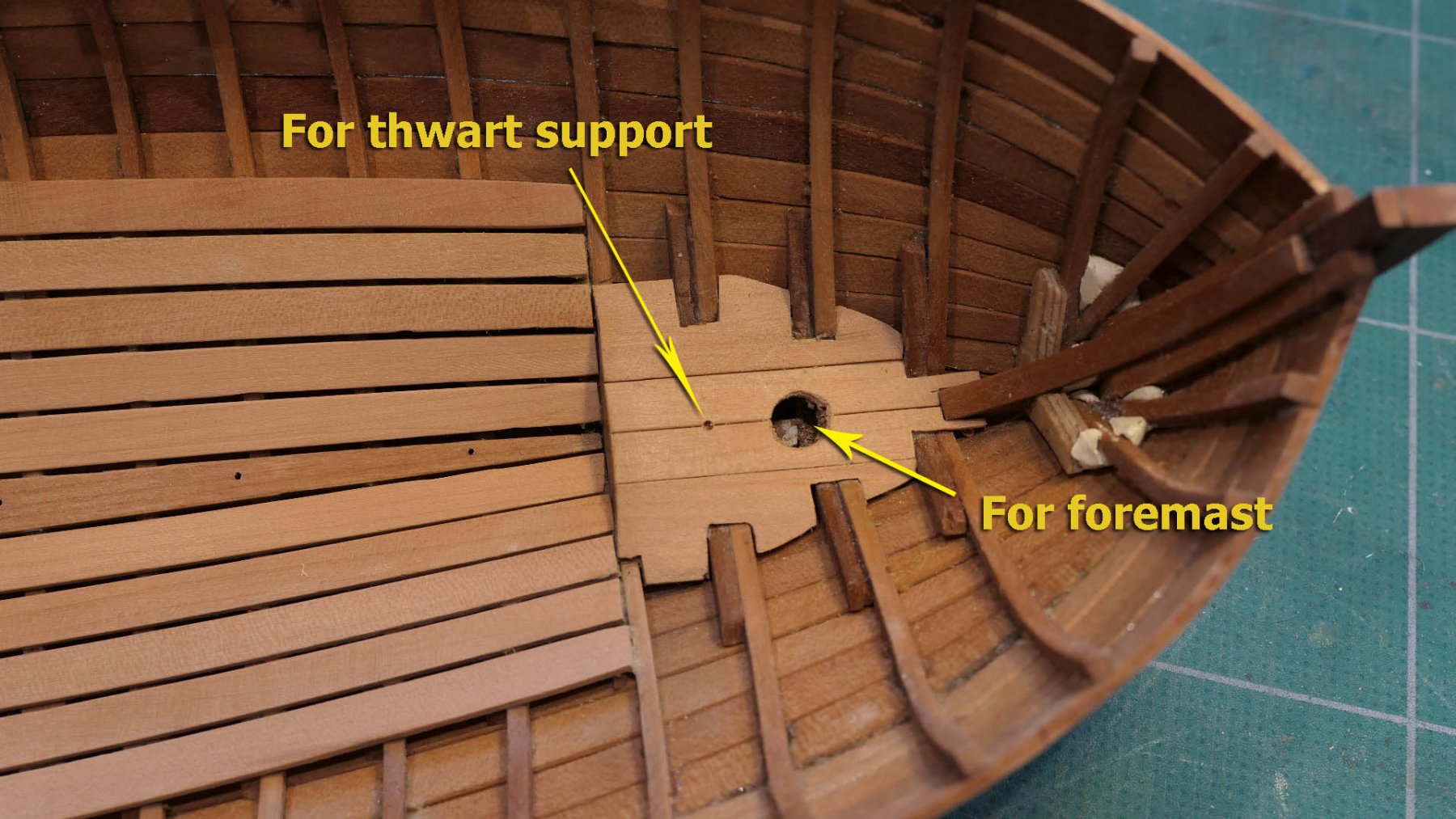
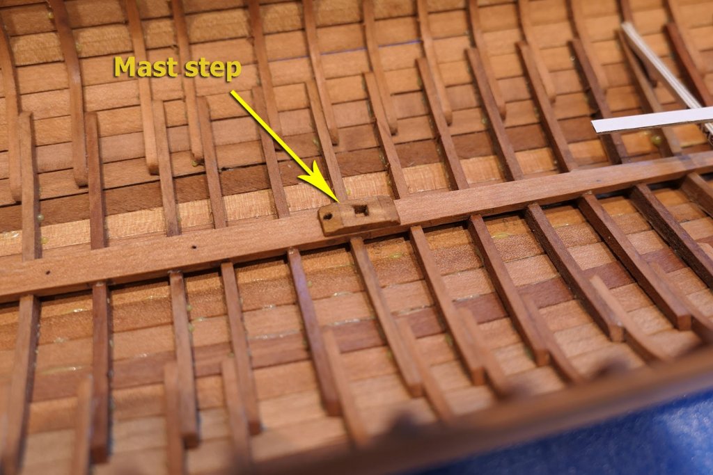
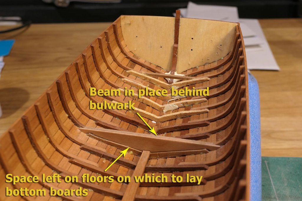
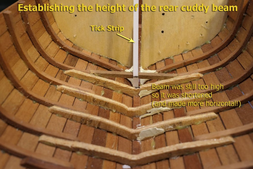
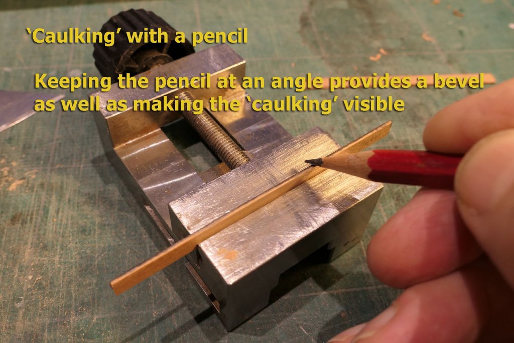
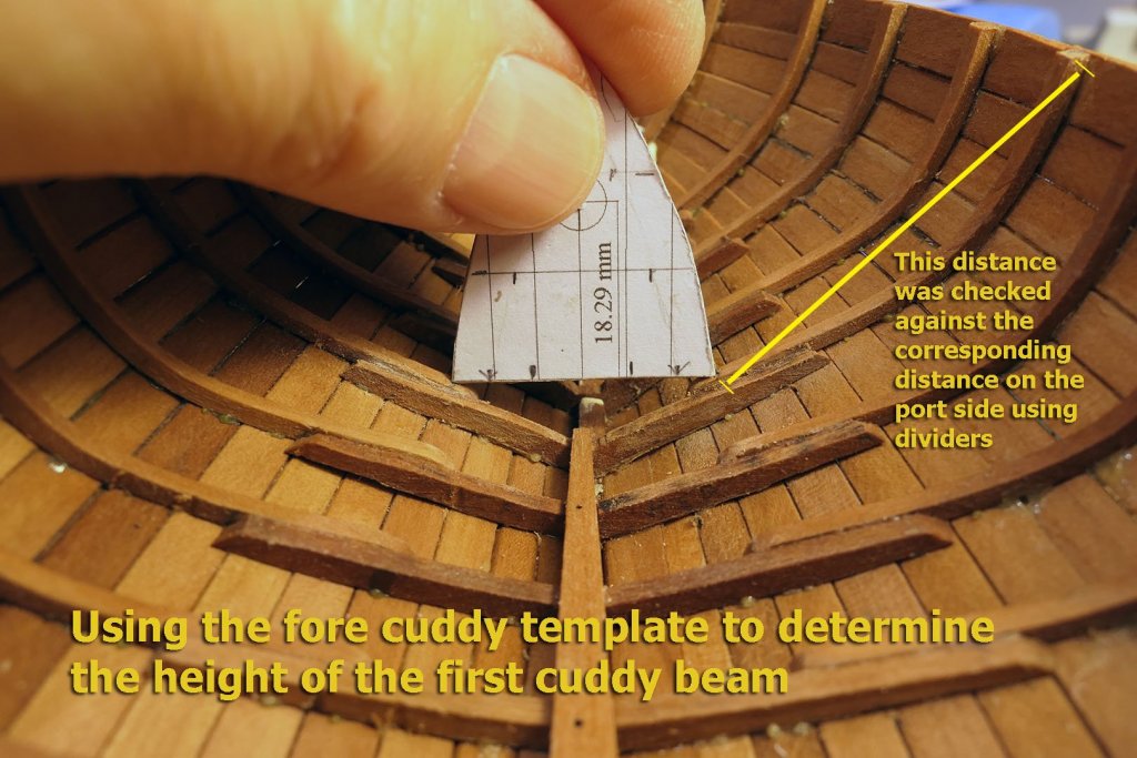
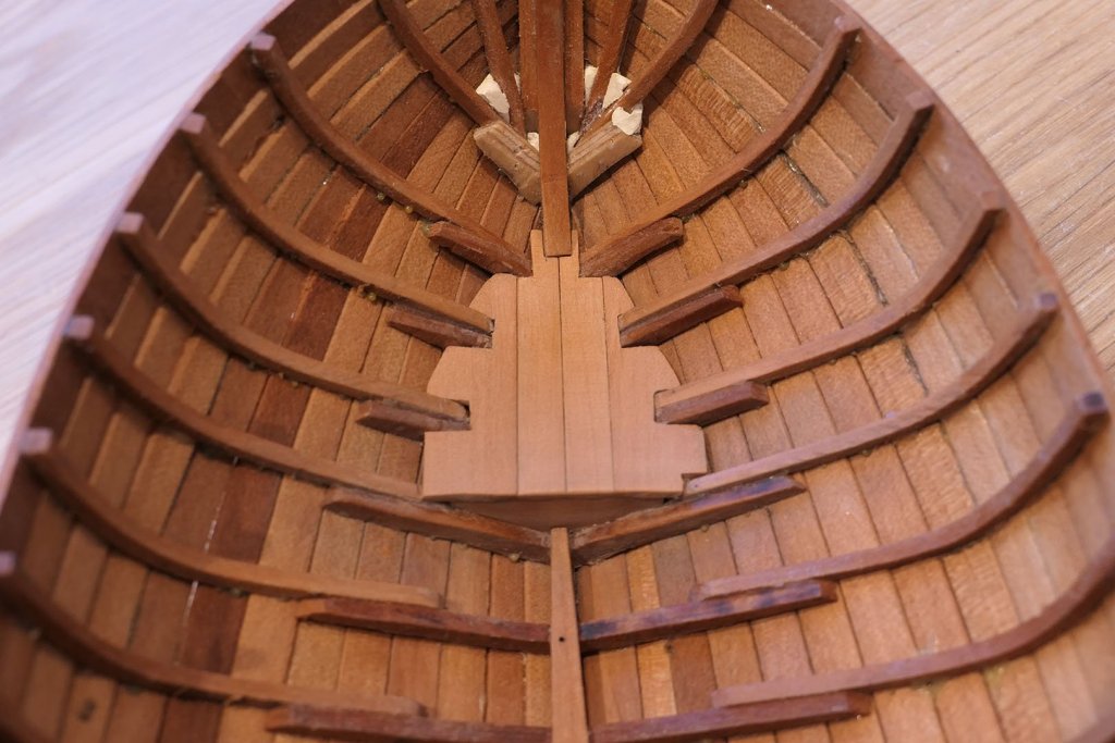
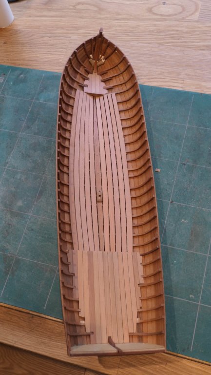
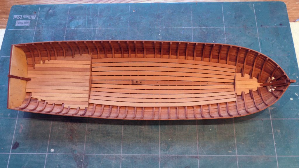
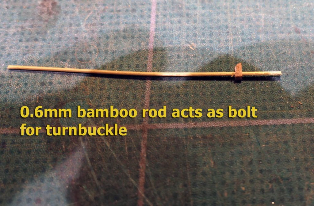
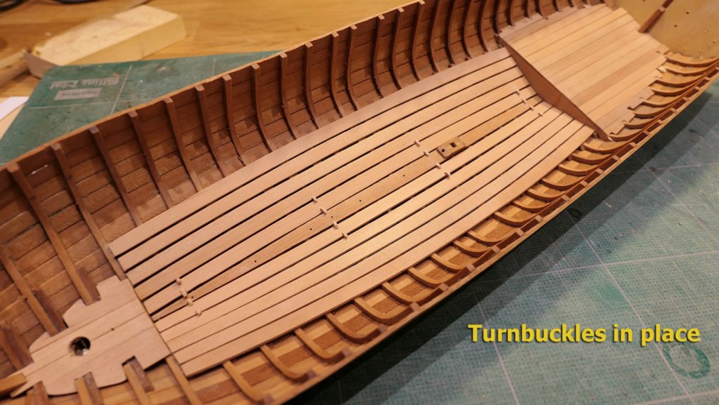
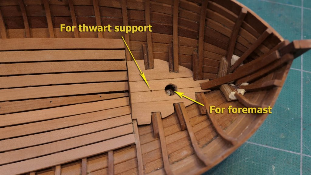
Mainmast step There was no difficulty pulling the hull off the mould (because of the over-liberal coating of wax and silicone spray), and the ends of the futtocks were removed flush with a cutting disk and sanding stick. The mainmast step was fashioned from a small piece of scrap pear, and holes drilled for the mainmast as well as the hole for the thwart pillar. The mainmast hole was cut square with a 2mm chisel. Stern sheets The key to the process of installing the stern sheets is getting the correct height for the support beams. The booklet suggests starting with the beam at the fore end, but I found it easier to make the small bulkhead that lies at the fore end of the sheets and which supports them. I reckoned it would then be very easy to stick the fore beam to the bulkhead and to the floors at either side. Plan 4 includes a cross section of the hull at rear frame 4, the site of the bulkhead, so it was easy to determine its outline from the plan. The next thing is to determine the height of the rear beam for the cuddy. This can be done quite easily from Plan 3 I then took a strip of paper to mark the height of the beam and then adjusted the rear beam until the correct height was obtained. The following picture shows the beam as too high, so it was re-adjusted until the height was correct. Then the intervening beams were laid using the fore and aft beams as reference points. Cutting the stern sheet boards was then straightforward, cutting notches for the futtocks and mimicking the caulking with a pencil rubbed at an angle along one edge of each plank. It’s important to angle the pencil because that gives a slight bevel to the plank. The following picture shows the rear cuddy planked, without varnish. Fore cuddy The apron internal timber was fixed to the apron after simple bending using dry heat. The height of the fore cuddy planking was determined by its width at front frame 5. I had tried to use just the measurement of the height shown in plan 3, but came up with the following discrepancy: So I unglued all the beams with isopropyl alcohol, and started again. This time I determined the height using the rear edge of the card template I had made. I then used a tick strip to determine the height of the first beam and cut a bulkhead using the cross section at front frame 5 shown on Plan 4, which gave me the bottom outline. For the planking I opted to use wider planks along the sides as to have used 5 mm planking would have resulted in difficulties in cutting round the futtocks. The planks were also cut around the internal timber fixed to the stem (seen in the picture below). Bottom boards The bottom boards were cut using templates cut from the plan. Luckily these were very accurate, and even more luckily (since I had no pear sheets wider than 10mm) they all could be cut to the correct shape and width with 10mm wide strips. The planks were glued to the floors and separated using some 0.7mm thick strips I had in my scrap box. Finally holes were drilled for the foremast and the thwart pillar. Turnbuckles These were used to hold down the planks adjacent to the false keel (and to remove them to access the keel) and are nailed into the relevant floors. So I made a template for a strip of 1mm square wood. This helped me cut the turnbuckles to the correct size and place the holes accurately. Next up will be the cuddy side planks. Tony


- 124 replies
-
- 21
-
-
- longboat
- Chaloupe Armee En Guerre
- (and 1 more)
-
I can't really tell from the drawing that you sent what the question is, but I thought I'd check your measurements. I imported the drawing into TurboCAD and set as 64mm the left hand line you have for 1Av. I measured it from the centre of the outer line to the centre of the centre line. I then measured the right hand side in exactly the same way and it came to 63.92mm, a difference of .08mm. I personally would not regard that as an enormous difference, and certainly one that would be hard to see in normal model-making. I didn't bother to check the other measurements, but if you still have difficulties perhaps you could clarify the precise measurements and other aspects with which you have difficulty. I hope this was helpful, Tony
-
You can always make your own. There are lots of sites giving advice about this. My own mix is one third each of linseed oil, white spirit and polyurethane varnish. Tony
-
That made me laugh, aviaamotor! Don't worry, more will be coming. But after I've caught up with the amazing build logs such as yours! Thanks, Tony
- 124 replies
-
- 2
-
-
- longboat
- Chaloupe Armee En Guerre
- (and 1 more)