HOLIDAY DONATION DRIVE - SUPPORT MSW - DO YOUR PART TO KEEP THIS GREAT FORUM GOING! (Only 72 donations so far out of 49,000 members - Can we at least get 100? C'mon guys!)
×


tkay11
-
Posts
1,829 -
Joined
-
Last visited
Content Type
Profiles
Forums
Gallery
Events
Everything posted by tkay11
-
I don't know about Floquil, and I don't know what country you're from (which would make a difference as to advice), but I use ordinary walnut crystal dye in different concentrations for rigging -- as recommended by Frolich in his Art of Ship Modeling. It will stain from almost black to the palest brown imaginable according to your taste. It's mixed with water, which also makes it very easy to handle. It's very cheap, used by carpenters for lots of furniture types, and easily found on eBay (e.g. http://www.ebay.co.uk/itm/Victorian-Antique-Wood-Dye-water-based-wood-stain-Mix-with-Water-50g-/140885995955?hash=item20cd75b1b3:m:mv8_RBbZw1wgVyzhfp6oHaA) Tony
-
 Something I forgot to add to the log was that I discovered too late that it would have been very handy not to have fitted the top mast and the top cap before adding the shrouds. If I had not fitted the top mast and cap, it would have been much easier not only to tie the shrouds very easily, but also to fit the two sets of pendants (mast tackle and back stay) in the correct manner. I have now edited my build log accordingly. Tony
- 269 replies
-
- 1
-

-
- Caldercraft
- First build
- (and 3 more)
-
I also really really like all these friends I have on this forum. Must be that warm christmasy feeling from the telly. Tony
- 269 replies
-
- 3
-
-
- Caldercraft
- First build
- (and 3 more)
-
Right, you taskmasters, main stay now in really correct position. See the edited post at http://modelshipworld.com/index.php/topic/335-hmc-sherbourne-by-tkay11-–-caldercraft-–-scale-164-1763-a-novice’s-caldercraft-sherbourne/?p=373484. And while I was at it, I noticed the breaking hook on the port backstay which I fixed as well. Thanks again for the help! Tony
- 269 replies
-
- 1
-
-
- Caldercraft
- First build
- (and 3 more)
-
Thanks, Dirk. I was puzzling over the position of the mainstay -- especially as I thought it would cut into the rope. Petersson shows it where I have put it but now that you've mentioned it specifically, I am happy to agree and put it down to another of Petersson's or the model maker's inaccuracies. I now suspect he put it there because there wasn't enough room on the cross tree after all the other rigging put there. We don't have pictures of the model he took it from, and the model itself is in middle England in storage. I use TurboCad (TCW) for my drawings, and have lots in relation to the specific parts. Which ones would you be interested in? Which format do you want them in? I can save to DWF, DWG, DGN, DXF, EPS, PDF. Send me a PM and we can sort it out. Tony
- 269 replies
-
- 1
-
-
- Caldercraft
- First build
- (and 3 more)
-
Great to see this started, George. I'll be following with intense interest. Tony
-
For the record, here are the photos of the mainstay in its corrected position! Tony

- 269 replies
-
- 5
-
-
- Caldercraft
- First build
- (and 3 more)
-
Phew! That was a narrow escape! Just fixed it. Photos tomorrow. This just shows the enormous value of posting a log of the build. I probably would not have noticed it until I was much further into the build! Thanks again, Dirk!! Tony
- 269 replies
-
- 1
-
-
- Caldercraft
- First build
- (and 3 more)
-
You're totally right, Dirk. I just wasn't paying attention when I did it. It will be changed! Thanks for the correction. Tony
- 269 replies
-
- 2
-
-
- Caldercraft
- First build
- (and 3 more)
-
Thanks, Nils and Per. I'm not sure about 'beauty' (especially contrasting it with your own builds) but certainly very pleasing for me -- mainly just to achieve a build! And I'm certainly happy that people like the detailed descriptions. Tony
- 269 replies
-
- 2
-
-
- Caldercraft
- First build
- (and 3 more)
-
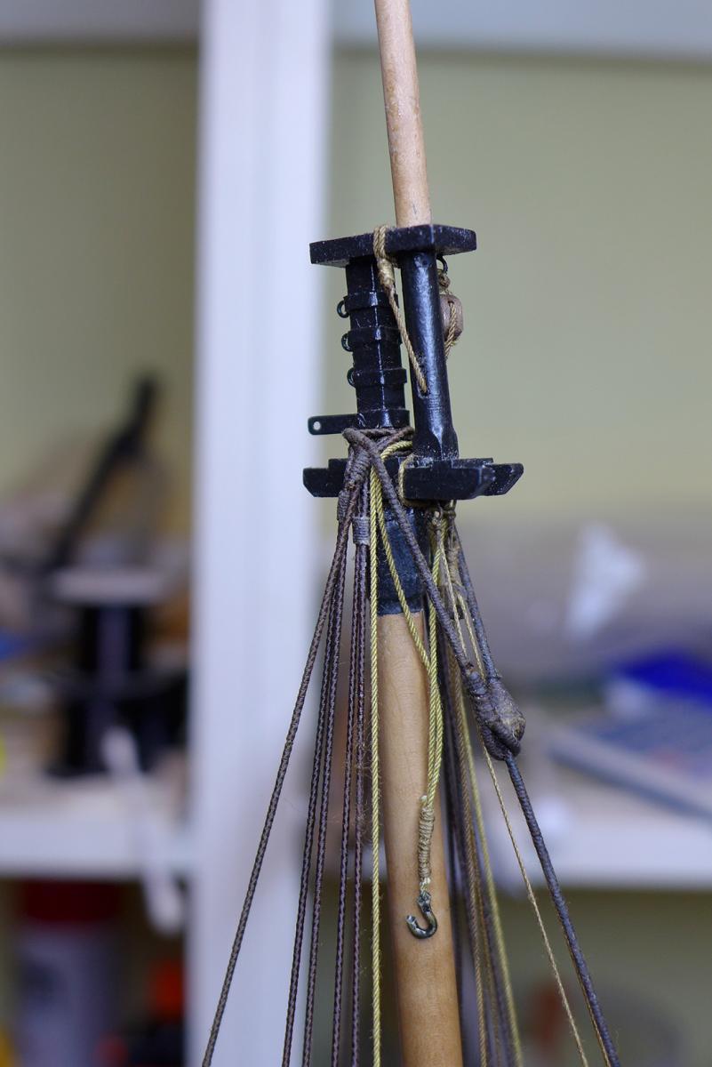
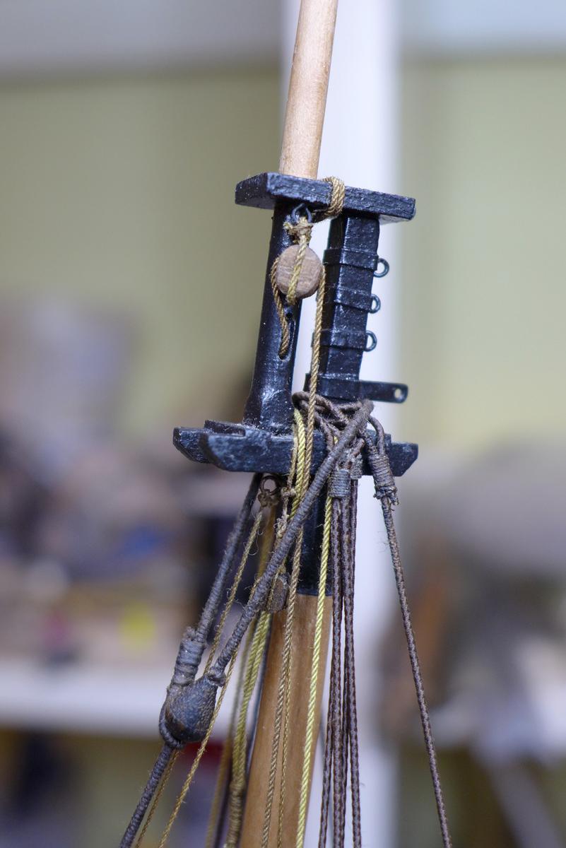
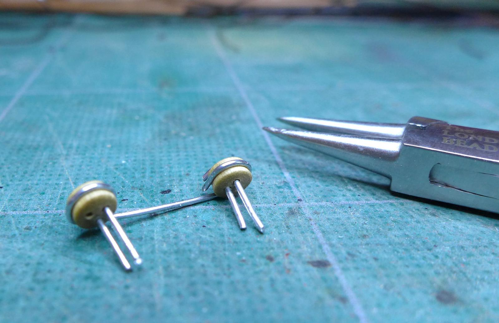
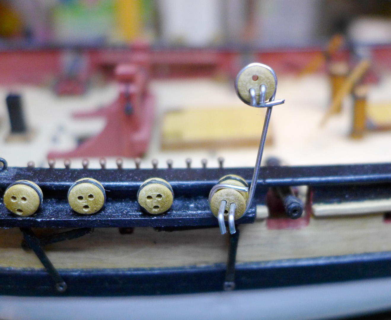
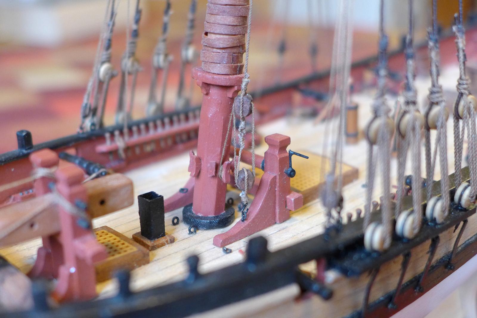
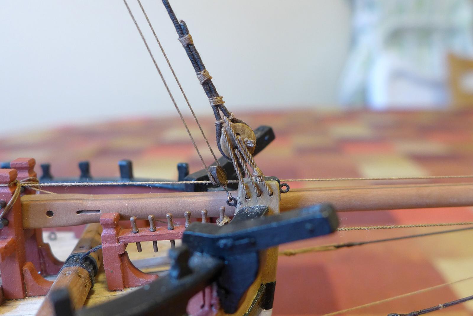
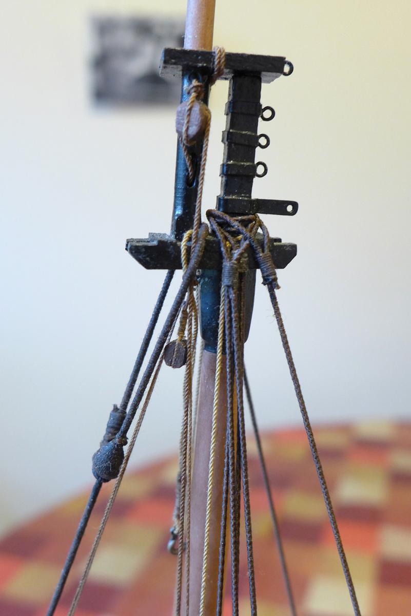
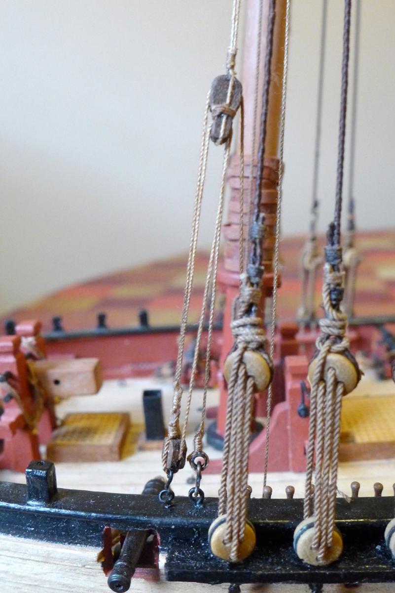
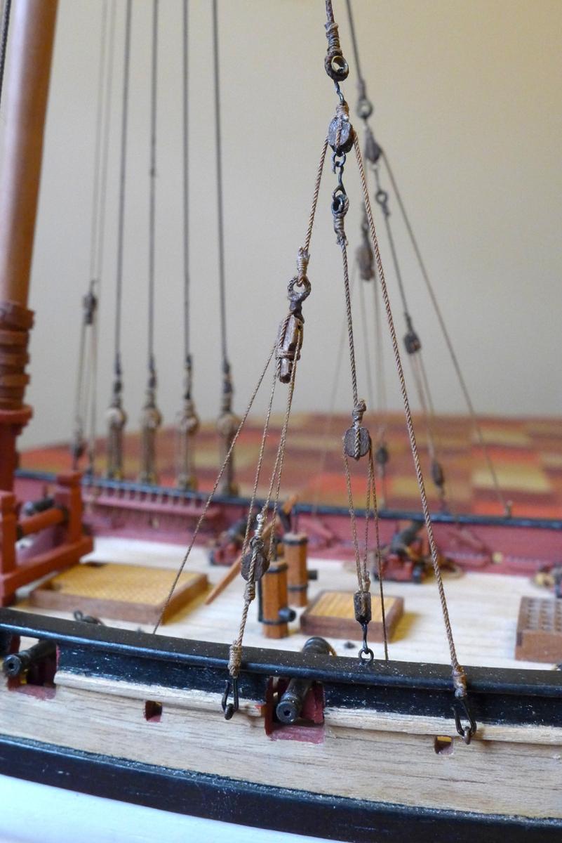
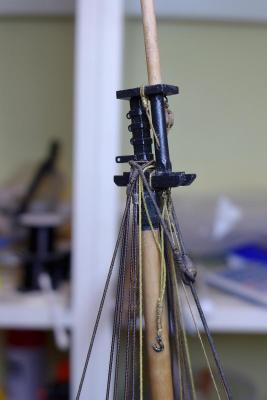
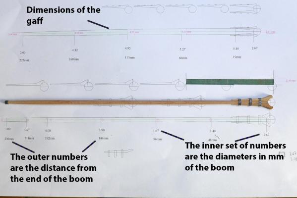
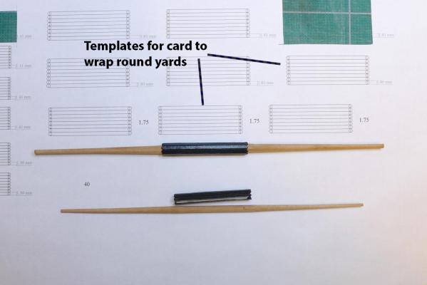
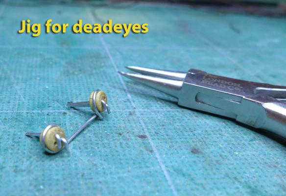
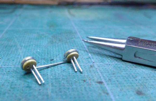
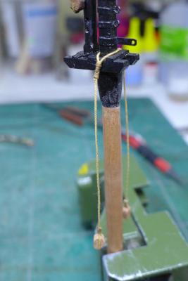
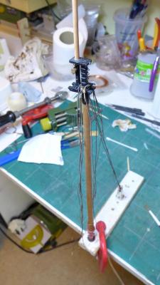
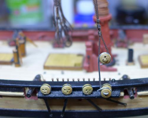
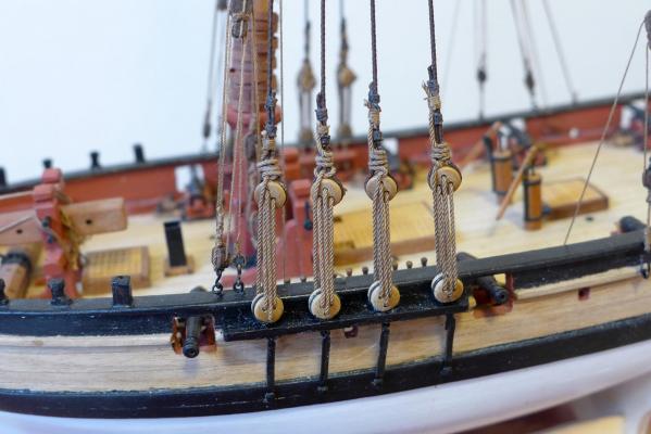
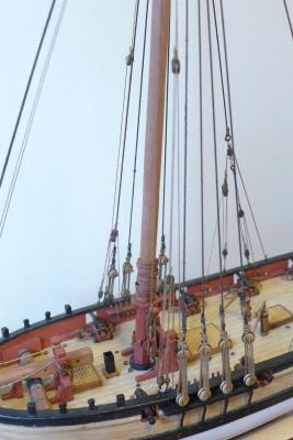
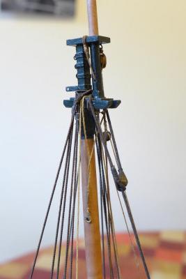
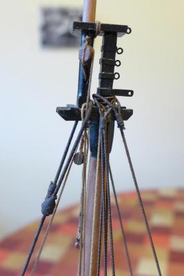
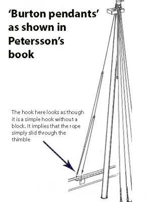
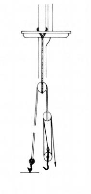
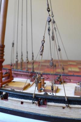
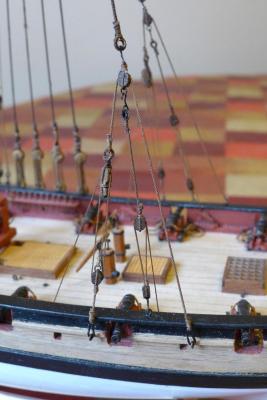
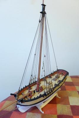
GAFF AND BOOM As with the mast, I made the gaff and boom out of pear, again using the dimensions given by Steel, as well as by Biddlecombe in his 1848 book on the Art of Rigging. The photo below shows the CAD drawings I made for the dimensions. YARDS Similarly I made the yards using Steel’s dimensions, and used a template to put the battens around the yards. You’ll note that I experimented with different batten widths for each yard so that the battens would fit perfectly. I painted all the yards black after gluing on the battens. You'll see them once I get to the stage of rigging the yards. DEADEYES I used a jig made out of paper clips for the deadeye spacing (following the idea on Hubert Sicard's site). You’ll see later how these were rigged. SETTING UP THE BACKSTAYS, SHROUDS, PENDANTS Following Petersson, I placed the pendants for the mast tackles first (he calls them Burton Pendants), along with the foresail halliard pendant, followed by the shrouds in their correct sequence. (I also placed the foresail halliard pendant at the same time, but forgot to take the picture -- you'll see that later in other photos). [EDIT: As a matter of interest to those interested in forward planning, I discovered too late that it would have been very handy not to have fitted the top mast and the top cap before adding the shrouds. If I had not fitted the top mast and cap, it would have been much easier not only to tie the shrouds very easily, but also to fit the two sets of pendants (mast tackle and back stay) in the correct manner.] I realised fairly quickly that it would be much easier to set up the mast in a small jig clamped to the desk so that I could keep the shrouds taut whilst stropping them at the top. TOP ROPE Next came the top rope, belayed to the ring on the jeer bitt and fastened to a cleat on the mast. The picture here shows only the lower end. You’ll see the part at the top later on (when you’ll also note that the distance between sheave and block is a bit too short, mea culpa). RIGGING THE SHROUDS TO DEADEYES This was done using the jig as follows. MAINSTAY Following the example of the models at Chatham, and the Petersson drawings, I left out a preventer stay and just have a main stay. The mouse is not done properly as I felt I hadn’t the skills to sew one, so I just made it on the wood lathe with a piece of wood. You'll notice I haven't yet put rings on the main stay to hold the foresail. This is because I'll be making them in the crossover pattern shown in Marquardt. You'll also notice the hook for the foresail halliard hooked to the back of the stem behind the main stay which links to a block round the cross trees and is fastened to the third belaying pin on the port side (which fastening you'll see in the photos relating to the deadeyes). NOTE: I do recognise that the tidiness of my rigging, especially at the cross trees, is not up to the standard of most others in this forum, but I put this down to lack of experience and something to learn from! AND OOOOOPS! [EDIT] Dirk noticed I'd slipped the main stay over the topmast. I really don't know how I did that as I knew better. All the same, it'll be changed! [EDIT 2] Pictures of the corrected main stay in post http://modelshipworld.com/index.php/topic/335-hmc-sherbourne-by-tkay11-–-caldercraft-–-scale-164-1763-a-novice’s-caldercraft-sherbourne/?p=373484 below. So far, the summary of the state of the mainstay and rigging at the cross trees is shown in the following two photos. You'll see here the lower yard sling which I haven't shown separately. I decided just to have a mast sling alone and have not included the mast halliards after a discussion I had about this in other posts. The general feeling was that the mast was often left just in the sling on such vessels, and Petersson also shows it without halliards -- as do some of the cutter models in Chatham. MAST TACKLES I made the Burton pendants to attach to the mast tackles as shown in Petersson. They are used to haul things to the deck or act in helping the stowing of anchors. However, I couldn’t make much sense of the diagram for the tackles used by Petersson. I had a discussion about this in separate posts, and people agreed that the diagram shown by Marquardt is more accurate. I therefore followed Marquardt. And here is Marquardt's drawing: And this is how the tackle looks on the model (note that whereas Marquardt shows a double block, I have used a fiddle block instead, in keeping with the tackle for the back stays): BACKSTAYS I followed Petersson in the rigging of the backstays, despite not seeing this type of rigging elsewhere. What he shows seems to be the use of the tackle at the backstays to add a loading tackle in the middle. The drawing comes from a contemporary model. This type of rigging required the addition of an extra cleat to the inside of the bulwarks as you can see. OVERVIEW The following gives the overview of work so far. You'll notice I haven't added the coils to the ropes on the belaying pins, but of course that will be done later in the build. Next up (sometime, in the future, in a galaxy far far away) will be the work on the Jib with its halliard and the yards. Tony


- 269 replies
-
- 10
-
-
- Caldercraft
- First build
- (and 3 more)
-
Very interesting and a good idea, wefalck. It's really enjoyable reading thoughtful comments like that. I'd also forgotten a discussion on this forum in 2013 (http://modelshipworld.com/index.php/topic/4200-milling-machine/), when Chuck chimed in (http://modelshipworld.com/index.php/topic/4200-milling-machine/?p=123846) saying, in relation to the Sherline he bought after a Microlux: Do I need more power and more speed (RPM)??? I dont really know...but the 2500-2800 rpm on the Sherline seems to be more than enough. The finish and clean surface of the wood (boxwood and Swiss Pear) tells me that the the speed is just fine. I think its important to recognize what the proper feed speed of your work should be and not rush the operations...that will give you a problem. Once again I am really abusing these machines. They are being used 4 or 5 days a week for hours at a time. My 17 year old son uses it with less care than I do...it has been holding up well and I literally make 20,000 blocks per month on it. I cut wood anywhere from 1/16" thick to 3/16" thick...the larger sizes require multiple passes with the endmills....Before making a decision I recommend visiting a friends shop to sit and use theirs and discuss the pros and cons...you have to see and feel the machine at work. It may be that a very sharp cutter as well as a well clamped and aligned mill bit can make up for a lack of speed. But then it may be that Chuck was using larger mill bits. I seem to remember he bought an extra special mill bit for the blocks. This discussion continues to be interesting, and I wouldn't be surprised if more will be said! Tony
-
Great, sensible comments, Mark and Paul. I'm really grateful for your experience. Tony
-
That's interesting, Nigel. I was looking at the Sieg mills in Arc Eurotrade on line, but I now see that Machine Mart is in Edmonton, which is quite close to me. So I may well go and have a look. I don't really intend to work with metal, but I've learnt from many other comments that once you enter this dark world of grown up toys you are easily sucked in deeper. Tony
-
Thanks, Nigel. I looked up the parts for the higher speeds at http://www.sherline.com/4335pg.htm, and there's no mention of warranty void. In fact they seem to encourage it. The only statement is that the mod is designed only for the DC motors from 1993 onwards. In the UK, Millhill supplies give a price of £78 for the pulley set alone at http://www.millhillsupplies.co.uk/catalogue/catalogue-sherline-accessories/. Tony
-
Wow! Now that's the cream on the cake! Great and full answer, so thanks again, Paul! Now I feel I really do get it! Tony
-
Aaah! Lovely words of wisdom, Paul, and not the kind we get out of trawling the web. Thanks a lot! Interestingly, though, nobody's commenting on why some people say that using ordinary mills at low rpm is not as good when milling wood. Or is that not really a problem? Tony
-
Thanks, Grant. Good idea, and not very expensive. I'd still like to hear a reply about the problems of using low speeds with small cutters in wood. Tony
-
This is an interesting point for me, Wefalk, as I'm trying to decide between a standard small mill such as a Sherline, and a Proxxon MF70. I'm still a little puzzled by the speed effect. I've read about feed rates and the need to match mill diameter, number of flutes and rpm, and it seems that the smaller the mill bit, higher revs allow a higher feed rate. So, for a 3mm mill bit, with 2 flutes, allowing a plunge depth of 3mm, 2000rpm allows a feed rate in hard woods of 6mm/15secs. Putting the rpm up to 12000 allows a feed rate of 36mm/15secs. Conversely, with a 0.6mm mill bit, the feed rate goes down to 7.2mm/15secs at 12000rpm, but only 1.2mm/15sec at 2000rpm My puzzle is whether, when using a lower speed mill, it makes any difference to the smoothness of the cut or level of burning if you just feed the wood at a slow rate. Is it that the only difference is the patience you need to feed the wood slowly, or is it that there are other disadvantages to milling wood with very small mill bits (e.g. 0.6mm, 1mm, 2mm) at low rpm? I've seen wonderful work with the MF70 in several scratch builds on this forum, but equally so with Sherlines and other standard small mills that only turn at up to 2200rpm. Any comments or advice will be very appreciated! Tony
-
Imperial or metric for lathes and mills?
tkay11 replied to tkay11's topic in Modeling tools and Workshop Equipment
Yes, I do agree, Nick. When I have to make conversions it'll be for use with metric-based systems -- which I'm already into, certainly in my head. Tony -
Imperial or metric for lathes and mills?
tkay11 replied to tkay11's topic in Modeling tools and Workshop Equipment
Neat idea, Mark. One that I'll likely follow. Thanks. Tony -
Imperial or metric for lathes and mills?
tkay11 replied to tkay11's topic in Modeling tools and Workshop Equipment
Thanks grsjax, redshirt, David and Bill. I'm relieved at the answers as I work entirely in metric, but thought I'd better check in case there was something I was missing. Tony -
Imperial or metric for lathes and mills?
tkay11 replied to tkay11's topic in Modeling tools and Workshop Equipment
Thanks, Shiloh. Nice answer. Tony -
This may well be a pointless question. Nevertheless, and just in case there is someone willing to humour me, I'll ask. It's whether for ship modelling there's any advantage to use a lathe or a mill in imperial rather than metric, seeing that the original plans are mostly in imperial measurements. An alternative to this question is its complementary one: why would one choose an imperial-based lathe or mill over a metric one? My suspicion is that it wouldn't make much difference, especially as scaling down by 1/48 or 1/64 will mostly involve decimals in either of the two systems. Any takers? Tony