tkay11
-
Posts
1,829 -
Joined
-
Last visited
Content Type
Profiles
Forums
Gallery
Events
Everything posted by tkay11
-
 Thanks, Frank. I agree totally. My comment was just to point out that this has nothing to do either with being 'sissy' or with being 'a solid tough breed' -- whatever those might mean. Tony
- 649 replies
-
- 6
-

-
- dunbrody
- famine ship
- (and 2 more)
-
Wonderful! I've much enjoyed this one, and look forward to the next! Beautifully finished. The sails are especially pleasing and well crafted. Thanks very much Tony
- 293 replies
-
- 2
-
-
- pickle
- caldercraft
- (and 1 more)
-
Cholera and the other illnesses causing death among the passengers, like TB and plague, caused death amongst all types of people. Well-fed officers were as prone to these problems as the privates in the various wars of the time. The major problem was not the starting health or fitness of the people but the extent of contamination. The major variables are exposure, duration of exposure, concentration of bacteria and frequency of exposure. Tony
- 649 replies
-
- 5
-
-
- dunbrody
- famine ship
- (and 2 more)
-
It's great to see the sail set. Well done, done well! Tony
- 293 replies
-
- 1
-
-
- pickle
- caldercraft
- (and 1 more)
-
Lovely detailed explanations, Frank. Thanks a lot. Just to help those who might like this saw but are in Europe (so no VAT or customs), the holder can be bought for €7 from Ireland at: http://www.radubstore.com/index.php?main_page=product_info&cPath=77_112&products_id=312 The blades (4 types from superfine to coarse) are €3.70 each and the links for each of them are at the above address. The holder needs the Swann Morton ACM1 handle for another €4.95 (also linked at the above site). So the total cost with 4 blades without shipping would be €26.75. Tony
- 649 replies
-
- 6
-
-
- dunbrody
- famine ship
- (and 2 more)
-
Good advice, Daniel. I don't know if this has been mentioned in the discussions you refer to, but just in case some might not want to use CAD or Photoshop because of the expense, there are some free CAD programmes available (TurboCAD 12, Draftsight, SketchUp) as well as the free version of Photoshop CS2 which will scale pdf and jpg files very accurately. The reason for mentioning this is that I have found some scanners distort differently in the x and y axes, and these CAD and Photoshop programmes allow you to scale each axis to a different degree. Tony
-
Thanks a lot, Niklas and Clare, although I must admit to some embarrassment when I compare what I have done with so many other builds. I score myself about 8 out of 10 for perseverance, learning, explanation and experimentation, but probably 2 out of 10 for finish. Comments such as yours reinforce the wonderful ethos of this forum where people critique and support one another for our mutual benefit and learning -- all in the understanding that we all are our own severest critics and all go through these same initial learning steps. It goes to keeping us all motivated and striving to do our best. As for learning how to build a ship model the right way, Clare -- that really made me smile after I have been following the probing intelligence you have been using on the Alert and your exquisite builds of Japanese boats. Thanks again Tony
- 269 replies
-
- 2
-
-
- Caldercraft
- First build
- (and 3 more)
-
Great progress. There are lots of really great hints on most aspects of model making at the late Hubert Sicard's site called Ship Modelling for Dummies, which you can find at http://www.shipmodeling.ca/aaplandusite.html The site has a great number of videos as well as detailed hints and tips, mostly using jigs you can make yourself at extremely low cost. It costs USD40 for a lifetime's access, but is really worth it. I thought of this site since tapering masts using a drill is one of his specialities. Tony
- 79 replies
-
- 5
-
-
- lady nelson
- amati
- (and 2 more)
-
A question for al you users of scroll saws
tkay11 replied to michael mott's topic in Modeling tools and Workshop Equipment
The DS115 saw Mark refers to is now the DS 230/E. For those in Europe, you can buy it from SAT Berlin for €99.98, or £81.70. See http://www.satberlin.de/en/PROXXON-machines/Table-top-tools/PROXXON-Scroll-saw-DS-230/E-NO-27088. Tony -
As you say, it'll be painted over, so no need to worry. Just another learning experience. And don't worry too much about the rabbet as it's not so hard to line the planks up -- as you say. Lots of modellers use filler if they don't line up. Again, as it'll be painted there should be no worry. You might want to consider putting filler blocks between the bulkheads, especially at stem and stern. That would make the process of planking and fairing much easier. I used balsa, but next time I'll use something firmer such as pine or basswood/linden/lime. Tony
- 79 replies
-
- 6
-
-
- lady nelson
- amati
- (and 2 more)
-
ancre Le Rochefort 1787 by Niklas - 1:36
tkay11 replied to Niklas's topic in - Build logs for subjects built 1751 - 1800
Wonderful to see another Rochefort started. I too have the plans but won't be starting till I've finished my cutter. I'm looking forward to following your log -- no doubt it'll save me from making a lot of mistakes! You've made a great start. Tony -
I am travelling at the moment and on very dodgy connections, so cannot access my usual resources, but I remember a lengthy discussion about this on MSW1. At that time mention was made of the practice off frapping the ropes round the gun tackles, except on the occasions in the Navy when inspections were carried out. On those occasions the ropes were laid in coils on the deck. I don't think anyone has mentioned this idea on this thread so far, so thought I'd bring it up. It's what I decided to do (in a very clumsy way) on my Sherbourne model. Tony
- 1,051 replies
-
- 1
-
-
- cheerful
- Syren Ship Model Company
- (and 1 more)
-
Attaching a Cutter's foresail to its horse rail
tkay11 replied to tkay11's topic in Masting, rigging and sails
Thanks, Frankie. Sounds good. I'm at the airport now, so I'll look at this in more detail once I've arrived tomorrow and if I have a good connection. Tony -
Attaching a Cutter's foresail to its horse rail
tkay11 replied to tkay11's topic in Masting, rigging and sails
Thanks, John. That's quite reasonable, and the description was clear about terminating the sheet by frapping and hitching. I'm presume that would make adjustments to the blocks faster as well as not leaving more ends crossing the deck. Steel isn't here to argue and in the absence of reprimands about historical truth, so I think I'll go with the simple and straightforward solution with the two blocks as you suggest. Tony -
Attaching a Cutter's foresail to its horse rail
tkay11 replied to tkay11's topic in Masting, rigging and sails
Thanks, John. A lovely illustration. That's exactly how I would have done it if the description by Steel were just to the two blocks, and I agree it is the most likely and obvious solution. What threw me was the description by Steel of the to'ing and fro'ing "alternately, between the strap of the block and the seizing or dead-eye; then through the thimble at the clue" I really couldn't make head or tail of that. I also love your description -- it really gives life to the whole concept! Tony -
After the tremendous help I received regarding the nature of the horse for the foresail, I find I have a further quandary. How to attach the foresail to the rail. I find the description given by Steel to be very confusing. He says: "Sheets reeve through a block made fast to the horse with a thimble, or, in some sloops, a dead-eye iron bound, and through a block at the clue, and so on, alternately, between the strap of the block and the seizing or dead-eye; then through the thimble at the clue, till the whole sheet is expended; then frapped together and hitched." I really cannot envisage this. It seems to say that the sheet is bound to the clue, then directly to a block at the horse, then to a block also attached to the clue, then to the seizing or dead-eye, then to the strap of the block at the clue then (after going back and forth 'between the strap of the block and the seizing or dead-eye') through the thimble at the clue and, when the rope is spent, frapped and hitched to the layers of rope so formed. I can't find a picture showing this, apart from a very indistinct picture from Cole's build of the Alert. I'd therefore be very grateful if someone could explain how the foresail is attached to the horse rail in this manner, especially if they could provide a drawing, illustration or picture. Just in case people reply after tomorrow afternoon, I'll be on a three-week trip starting mid-day Thursday 10th, and so may be unable to reply until I can find suitable wi-fi connections wherever I'll be staying. Thanks in advance Tony
-
Just to add to the advice of others, I have used PVA for the vast majority of the build. CA is really not advised in general, but there have been many times when it has come in very useful. Thus for making very quick jigs with wood, and stiffening the ends of ropes before threading it really is useful to have a bottle of CA handy. Also, and please don't tell anyone on this forum, I have, yes I have, used CA a bit when stropping blocks. But I've sworn to give up the habit -- 'onest, guv! (It's only 'cos I's a learner, after all). Finally fast-drying epoxy has been truly indispensable for a number of tricky jobs that require a fairly quick but very strong bond -- e.g. fastenings such as eyebolts into wood by brass eyebolts or other metal fastenings. So it's worth having a set of tubes of that handy. Then you'll very probably come across times when you curse the fact that you've stuck something together only to find it was a mistake or you need to go back. Isopropanol is great for PVA and you can buy 250ml off eBay for very low prices. Then for CA acetone is very handy -- especially if you have some stuck to your fingers (also very cheap on eBay). Finally, I use methylated spirit for cleaning off epoxy. Of course, when using PVA I nearly always have a damp sponge cloth or toilet roll nearby to wipe away immediate smears or to clean fingers. Considering the application of glue, I have mostly used matchsticks sharpened to a fine point to put dabs on small surfaces, and cheap paintbrushes to put diluted PVA on rigging. Some use syringes for PVA but I haven't found the need so far. Tony
-
Thanks, Kester. Now I'll have to make my mind up. It's like having too many goodies on the table. Tony
-
Nice thoughts, Frankie. Thanks! Tony
-
Oh dear. Shame on me. I forgot to look at Gregor's Sherbourne. He has the horse very neatly laid out at http://modelshipworld.com/index.php/topic/2288-hmc-sherbourne-by-gregor-–-caldercraft-–-scale-164-1763/?p=186350. I had totally forgotten. He also has the same reference to Roger Cole's build of the Alert. Sorry, Gregor! And that was only two years ago. Memory clearly failing. Tony
-
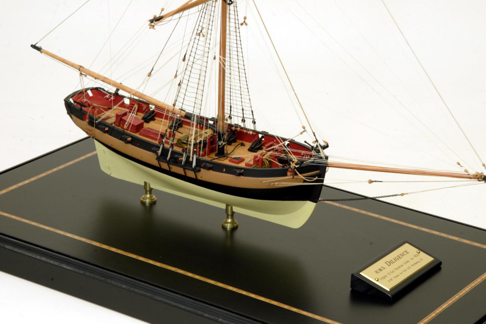
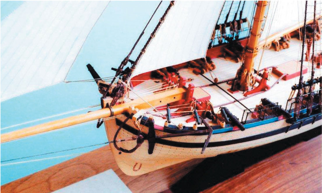
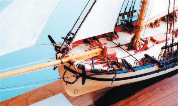
That's perfect, Chuck. Thanks a lot! Those plans are absolutely perfect for me. I should have thought of looking at plans. I'm really glad I didn't go with the short version I had initially thought of. Interestingly, after further research, I came across the following photo on http://www.shipmodel.com/models/diligence-full-hull-nav-: Then I found Roger Cole's build of the Alert with the following picture: Both of these show rails similar to the ones in the plans you linked me to. As to my statement that I'd see the rail across bulwarks, I really can't remember where that was so I presume I remembered incorrectly. Tony

-
I want to place a horse rail for the sheet of the foresail on the Sherbourne (English Revenue Cutter 1763). I have seen pictures of rails that run right across the deck along the top of the bulwarks, but it seems from a look at Steel's and Marquardt's books that the horse would lie quite close to the deck just in front of the mast. Unfortunately none of the models of cutters I have seen in the museums have such a horse, even though all the sources refer to one. Goodwin's AOTS book on the Alert doesn't show one either, although there is a tantalising reference in one drawing of the rigging which shows the sheet tackle disappearing from sight on to the deck with the caption 'secured to horse'. In fact the only one I recall seeing on a model is Kester's (Stockholm Tar) build of the Sherbourne. There he placed the rail across the fore gratings but I recall he was uncertain himself at the time of how exactly he should place it. My question is how wide across the deck should the horse rail go? My initial thought was to make it the same width as the one for the mainsail at the taffrail, but when I placed it on the deck it looked a little short at just under 4 ft (45 inches) full size on a deck whose width is nearly 19 ft. The other thing, of course is the height. I've thought 15 inches would be ok, but again am more than willing to hear from the experts. Any advice or wisdom will be gratefully received as usual. Tony
-
HMS Alert 1777 by Jaekon Lee - 1/64
tkay11 replied to Jaekon Lee's topic in - Build logs for subjects built 1751 - 1800
That's odd. I was wondering exactly the same thing yesterday. Tony -
Thanks, Peter. I had been following your log up till mid-January with great interest, as I was intrigued by the Pickle following a BBC television programme about the replica and her type of ship. The discussion about the accuracy and plans on your log is fascinating. So I was delighted by your reminder as it made me go back to see what you did with the sails. I must admit that the look of the cotton is (to my eyes) still preferable, so I'll probably try cloth next time round. I do have some fine 0.4mm thick 22gsm silk pongee cloth I bought just in case -- when I was still trying to decide. It's thinner than the Modelspan, so probably would be ideal. I just didn't have the courage to ask my wife for a tutorial on her sewing machine and was intrigued by the idea of doing it with Modelspan. You can see the congee on Amazon UK at http://www.amazon.co.uk/dp/B006FHMGMC/ref=pe_385721_37038051_TE_3p_dp_1. It's great stuff. I take the idea about being becalmed. Even more likely when not floating in water. I've now added my name to your list of followers to make sure I keep up to date. Onwards! Tony
- 269 replies
-
- 5
-
-
- Caldercraft
- First build
- (and 3 more)