HOLIDAY DONATION DRIVE - SUPPORT MSW - DO YOUR PART TO KEEP THIS GREAT FORUM GOING! (83 donations so far out of 49,000 members - C'mon guys!)
×


tkay11
-
Posts
1,829 -
Joined
-
Last visited
Content Type
Profiles
Forums
Gallery
Events
Everything posted by tkay11
-
 Yes indeed, Dirk, I know you'd have started again. In fact I thought of you and Mark when I made my decision. No regrets. None. Not at all. Well, maybe a teeny weeny bit ... I hope you've recovered after your Confederacy agitations. For a moment I thought we might be seeing more of the Sherbourne build. As for your learning about the Triton, well, I reckon most of the others who've done this have lots more to give. I'm still in awe of some of the Triton cross-sections. All the same, thanks a lot for continuing your encouragement -- it means a lot! Tony
- 132 replies
-
- 4
-

-
- triton cross-section
- cross-section
- (and 1 more)
-
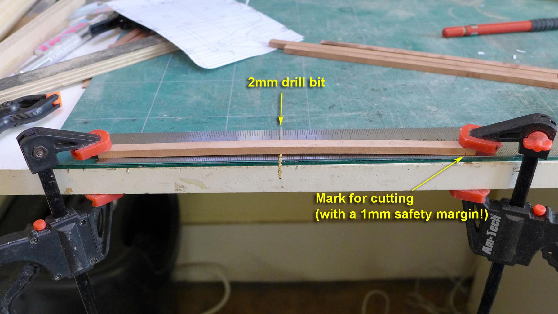
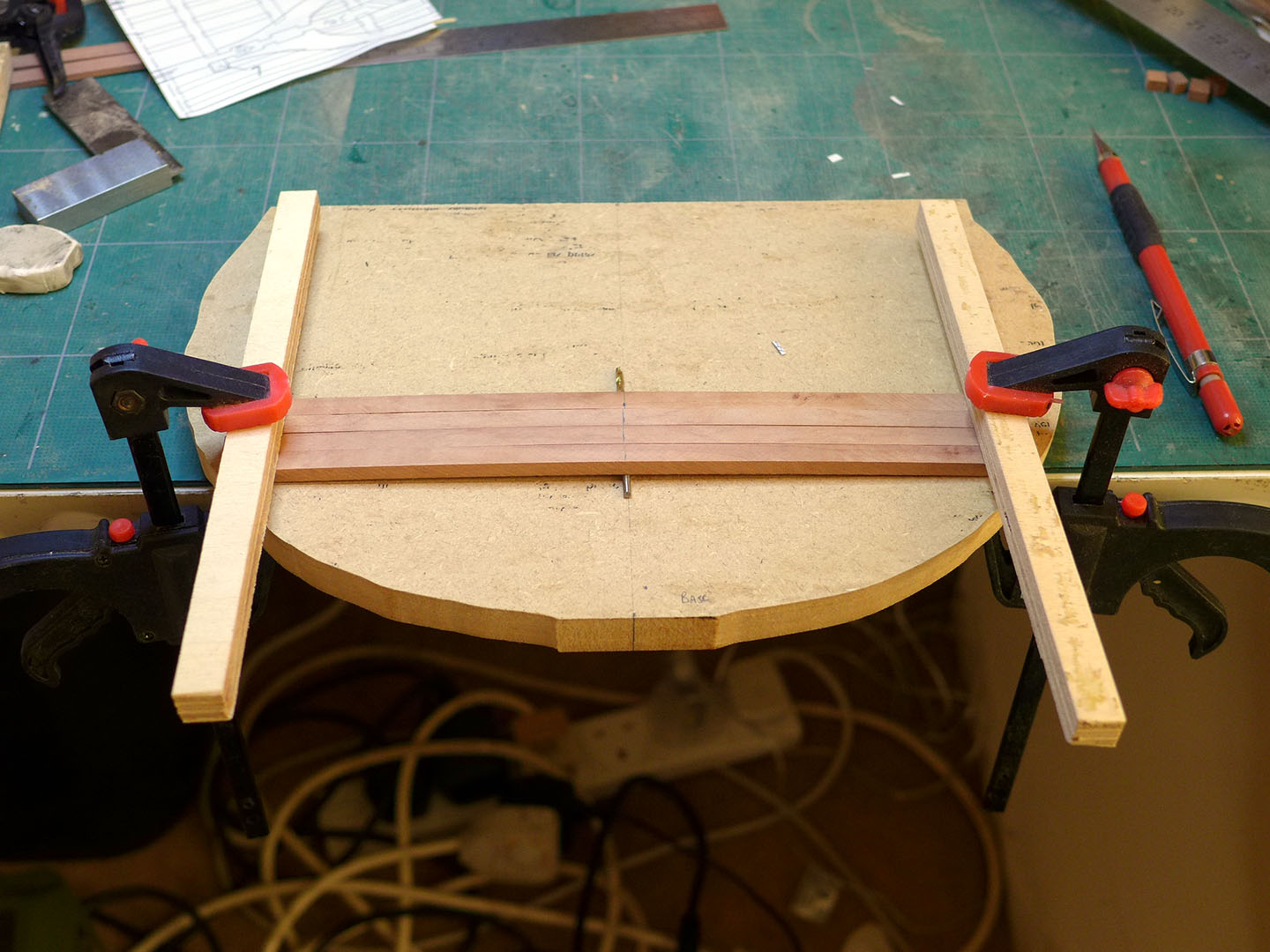
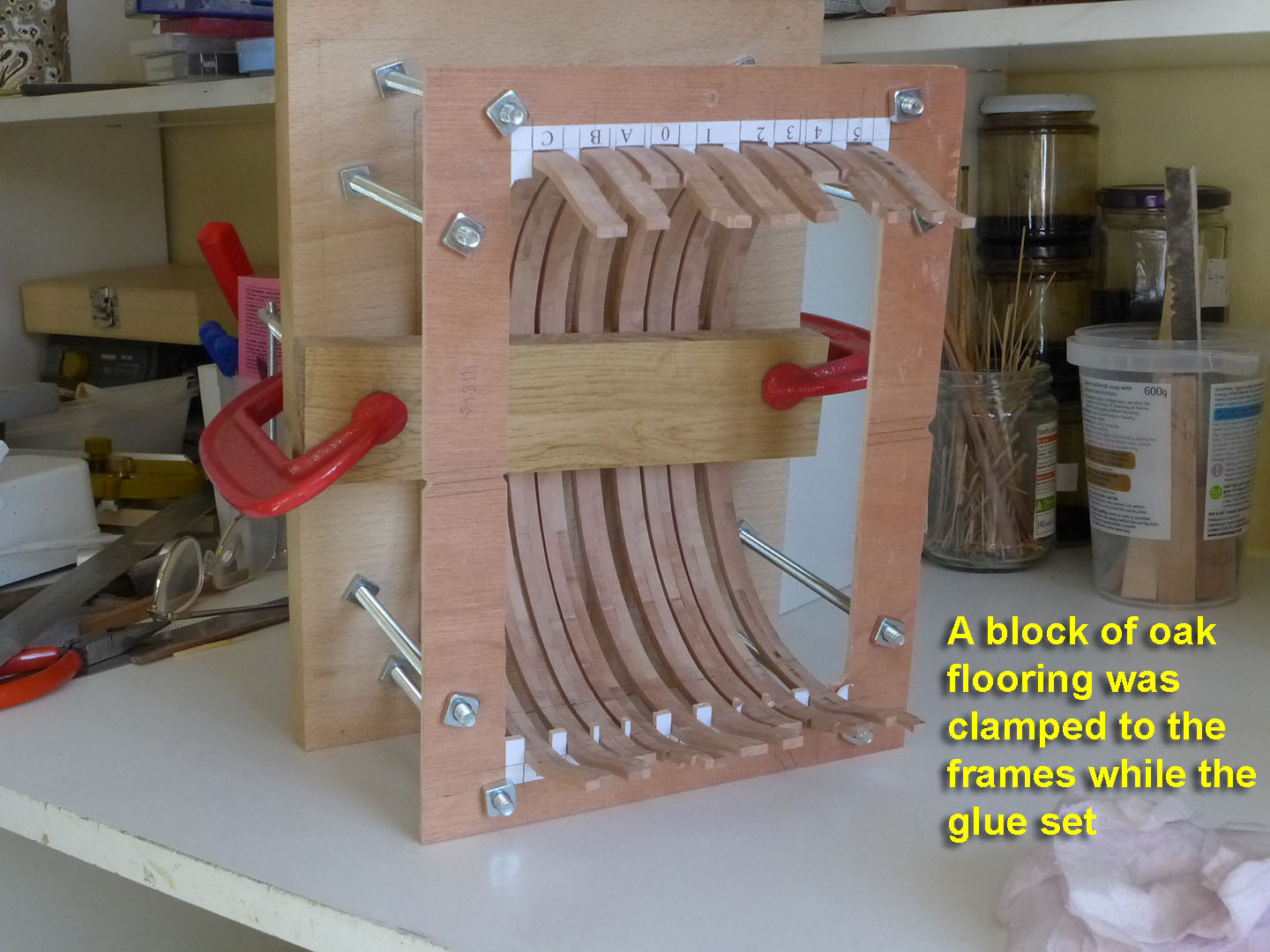
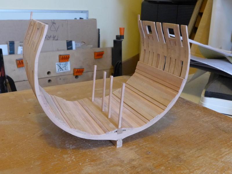
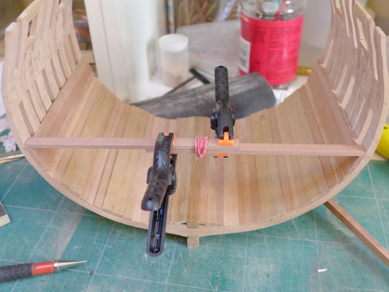
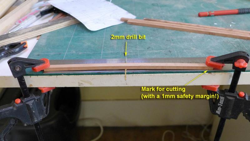
After clarifying for myself what I mean by a ‘learning exercise’ (focus on learning the basic techniques more than attempting a beautiful finish) I decided to continue with the build, albeit with the imperfect frame sanding. Also, as before with my Sherbourne build, I am using this log not only to clarify my own thinking, but also to help other newbies like myself should they come across similar puzzles and questions to the ones I find as the complexities arrive at each stage. Part of this decision was not to make removable limber boards, and to avoid treenails. I thought that doing these precisely is beyond my skill level at present, especially as I’m still struggling with how I might make the angles on the limber boards more precise. Pillars in the hold These I made to scale of 6” square, with a tapered chamfer starting from 8” above the platform and within 6” of the beams as shown by David Antscherl in his book on the fully framed model. Also following his advice, I made 1mm dowels for the pillars and drilled corresponding holes in their bases and on the keelson. (You'll see the finished pillars with the chamfered edges later in this post). Planking After fitting the first 4 strakes outside the limber strakes, I fitted the lower deck clamps. In order to ensure they were at the correct height, I added another platform to my height jig and measured off the height at all four edges. I thought it best to measure out the spaces rather than use the planking shown in the plans, so I used a simple paper template to mark between the lower deck clamps and the bottom strakes. This showed that the thick stuff would not be able to lie exactly over the centre of where the first futtock joins were, although it hit exactly over the centre of the second, upper set of futtock joins. I then checked the setting of the hold pillars Lower deck beams I made up the beams to their actual size (rather than oversize) as I’m bending them with a jig. First of all I measured the width at each beam’s position using an idea from David Antscherl’s book. I then marked the beams for cutting by measuring them after bending them over a 2mm drill bit. The actual height I measured in the CAD programme was 1.97mm, but I thought this would be within the margins of multiple errors. I then transferred the cut beams to the following jig for bending: I am in the process of heating them with a very old hair dryer at occasional intervals over the next few hours until they achieve a stable bend: So the learning process continues, as I am sure it will continue to do so for a very long time! Tony


- 132 replies
-
- 12
-
-
- triton cross-section
- cross-section
- (and 1 more)
-
Tools and techniques used in the 18th Century
tkay11 replied to tkay11's topic in Modeling tools and Workshop Equipment
Another great resource! Thanks a lot, Bob! I've already downloaded and started reading! Tony -
Tools and techniques used in the 18th Century
tkay11 replied to tkay11's topic in Modeling tools and Workshop Equipment
Thanks a lot, Wayne. I'll follow through! Tony -
Tools and techniques used in the 18th Century
tkay11 replied to tkay11's topic in Modeling tools and Workshop Equipment
Very interesting, Wayne, and thanks for the thoughtful reply. What is 'MM' and how do I obtain the articles? Tony -
Tools and techniques used in the 18th Century
tkay11 replied to tkay11's topic in Modeling tools and Workshop Equipment
Thanks very much, Bob. Just the sort of thing I was looking for! Following the link given by Google Books, I think the printed version (slightly different title, but same source at Williamsburg) may be bought for USD 19.95 at http://shop.colonialwilliamsburg.com/Tools-Working-Wood-in-18th-Century-America. The ebook at UK£4.56 looks good value. They also have a DVD about cabinet making for the same price at http://shop.colonialwilliamsburg.com/The-Cabinetmaker-DVD. Tony -
With the oft-repeated discussions about which power tools to use, and the oft-repeated replies referring to the fact that they didn't have power tools in the 18th Century, I was wondering where to look for articles about the tools and techniques used at that time by ship modellers. I'd really like to know more about which tools were used, how they were made and the various little techniques that were used to achieve their perfect results -- especially in making Admiralty models. I suppose it's strongly linked to fine cabinet making, especially in miniature-- and there's probably lots of info on that. Obviously knives, blades, saws and chisels don't need much discussion, and I'm clear about the types of lathe used. But I'd be quite interested in accurate drilling, for example, or sanding techniques or the kinds of jig that may have been used. I'm sure lots of you have already considerable knowledge about this, so I thought I'd ask to see where I might start. Thanks for any replies or interest! Tony
-
Great to see another Jacinthe started. I too have the plans but won't be building until I've completed my Triton cross-section. I really look forward to your progress and will follow it closely. Tony
-
Ha ha! Mine will definitely not be a model I'll be keeping for display in our place or any other. Tony
- 132 replies
-
- 2
-
-
- triton cross-section
- cross-section
- (and 1 more)
-
Thanks, Mark. That's very useful. I'm now definitely leaning that way too. In fact writing out in the log made the decision much easier. That's another value of composing a log -- it composes the thoughts too! It seems like I'm following your footsteps even more closely than I had envisaged! Tony
- 132 replies
-
- 3
-
-
- triton cross-section
- cross-section
- (and 1 more)
-
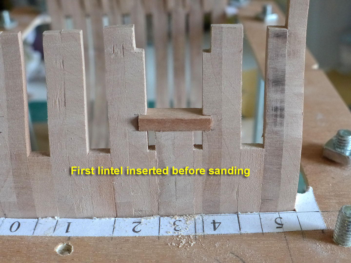
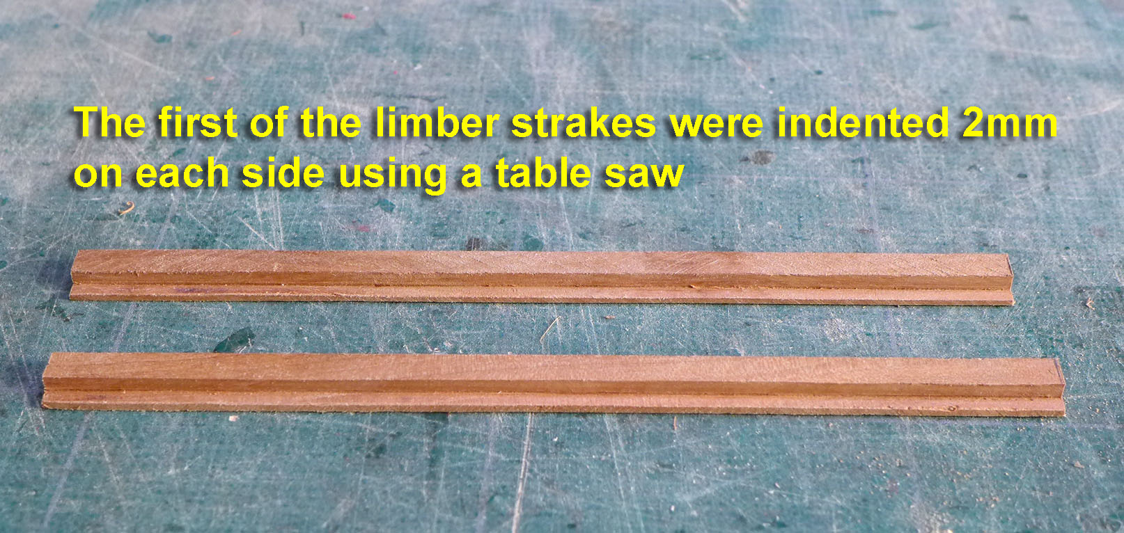
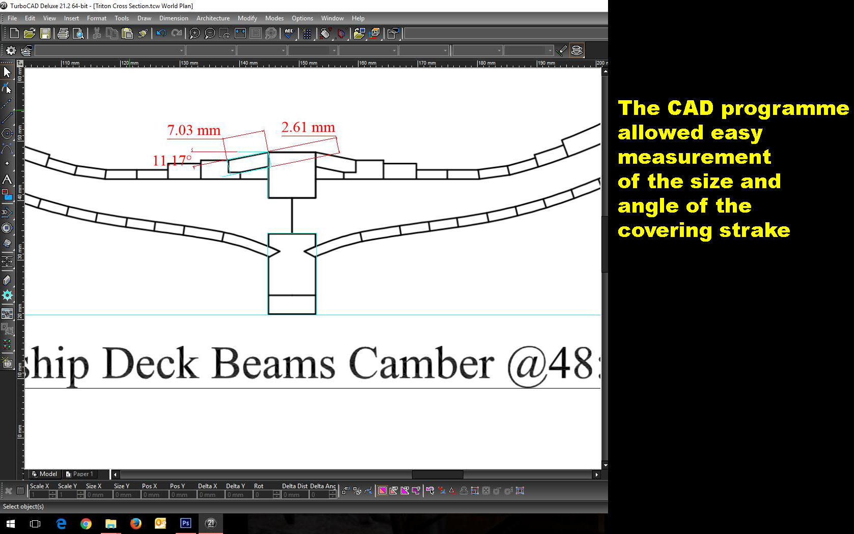
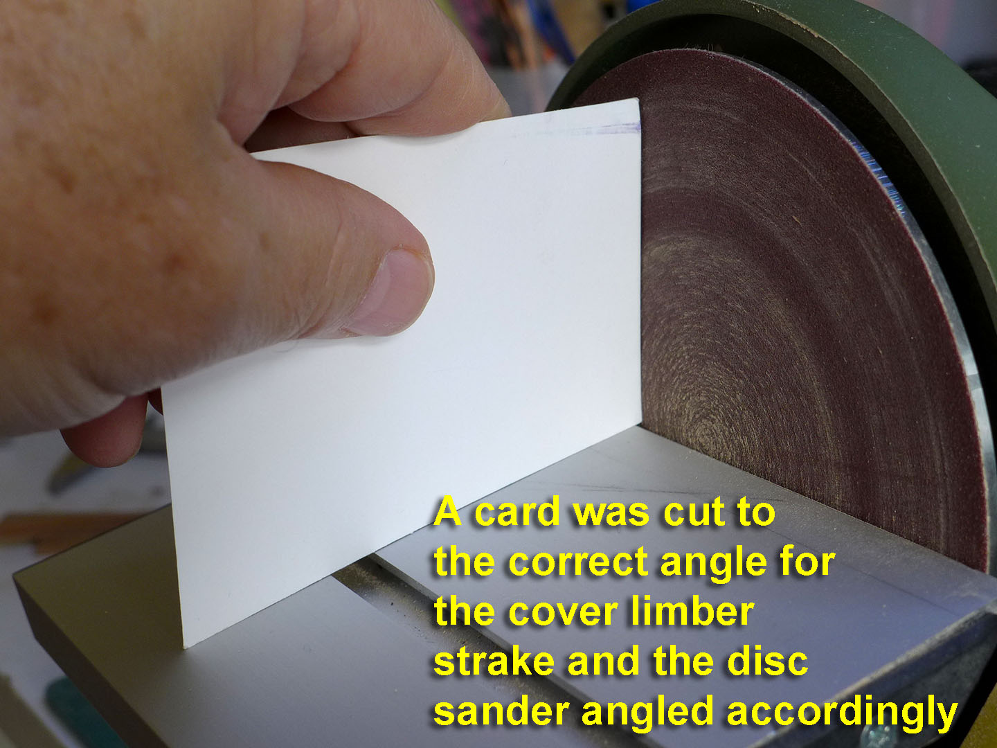
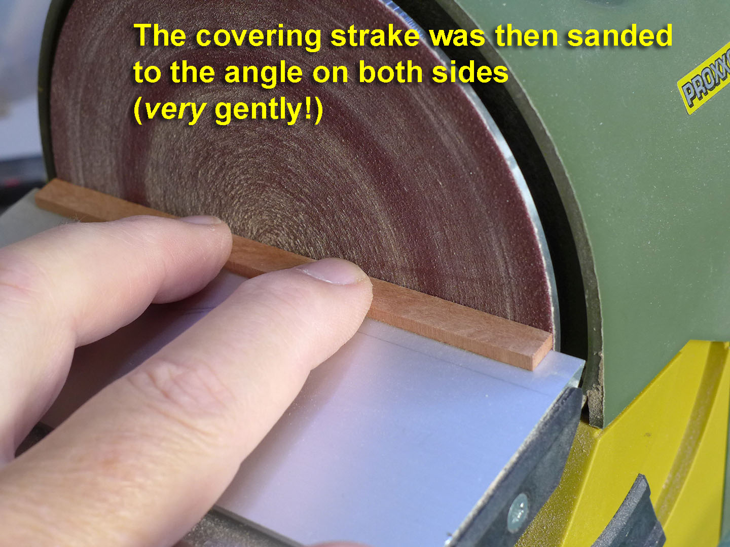
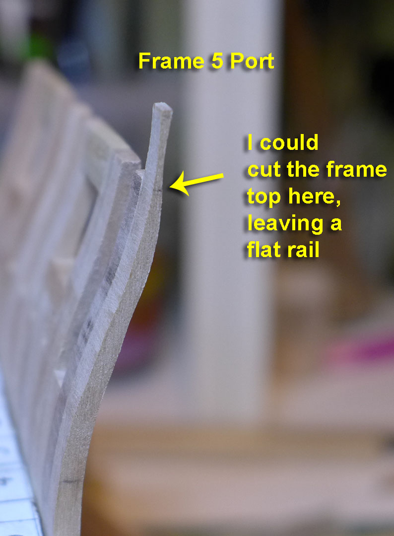
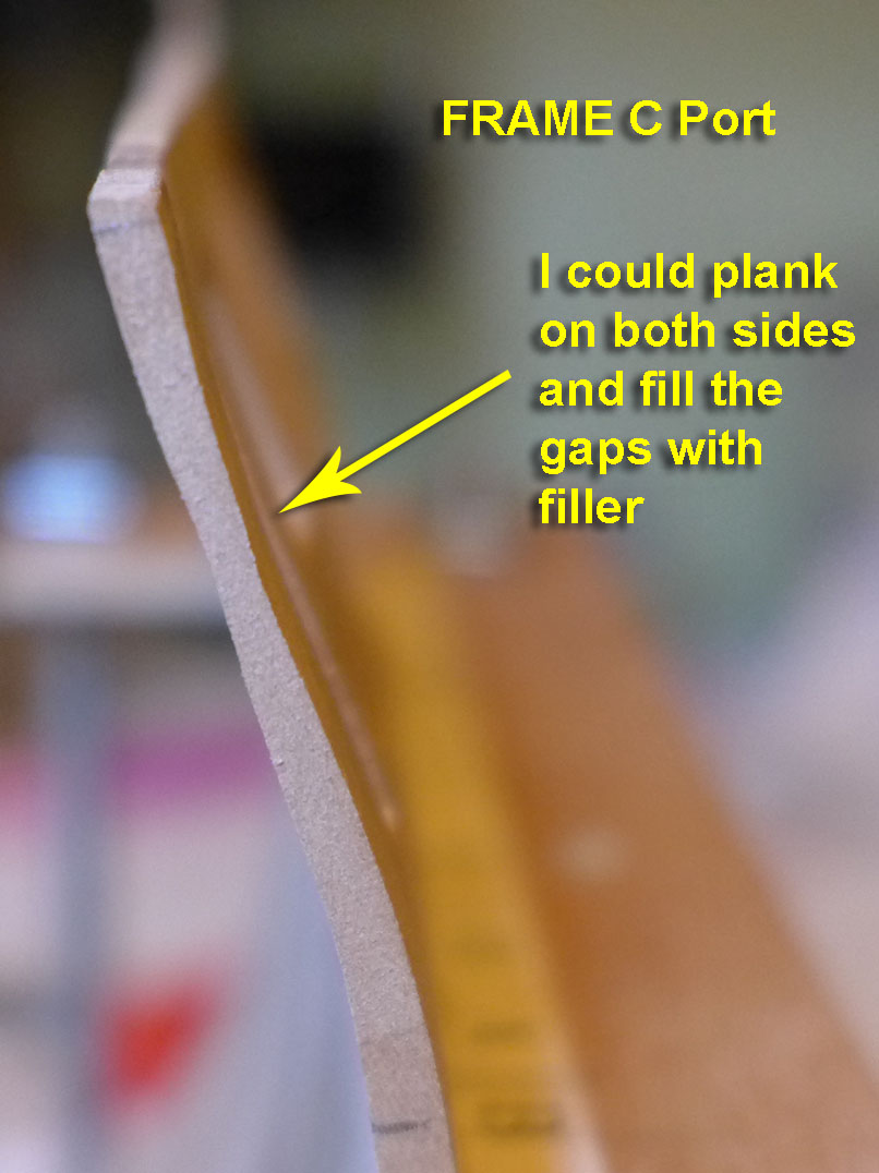
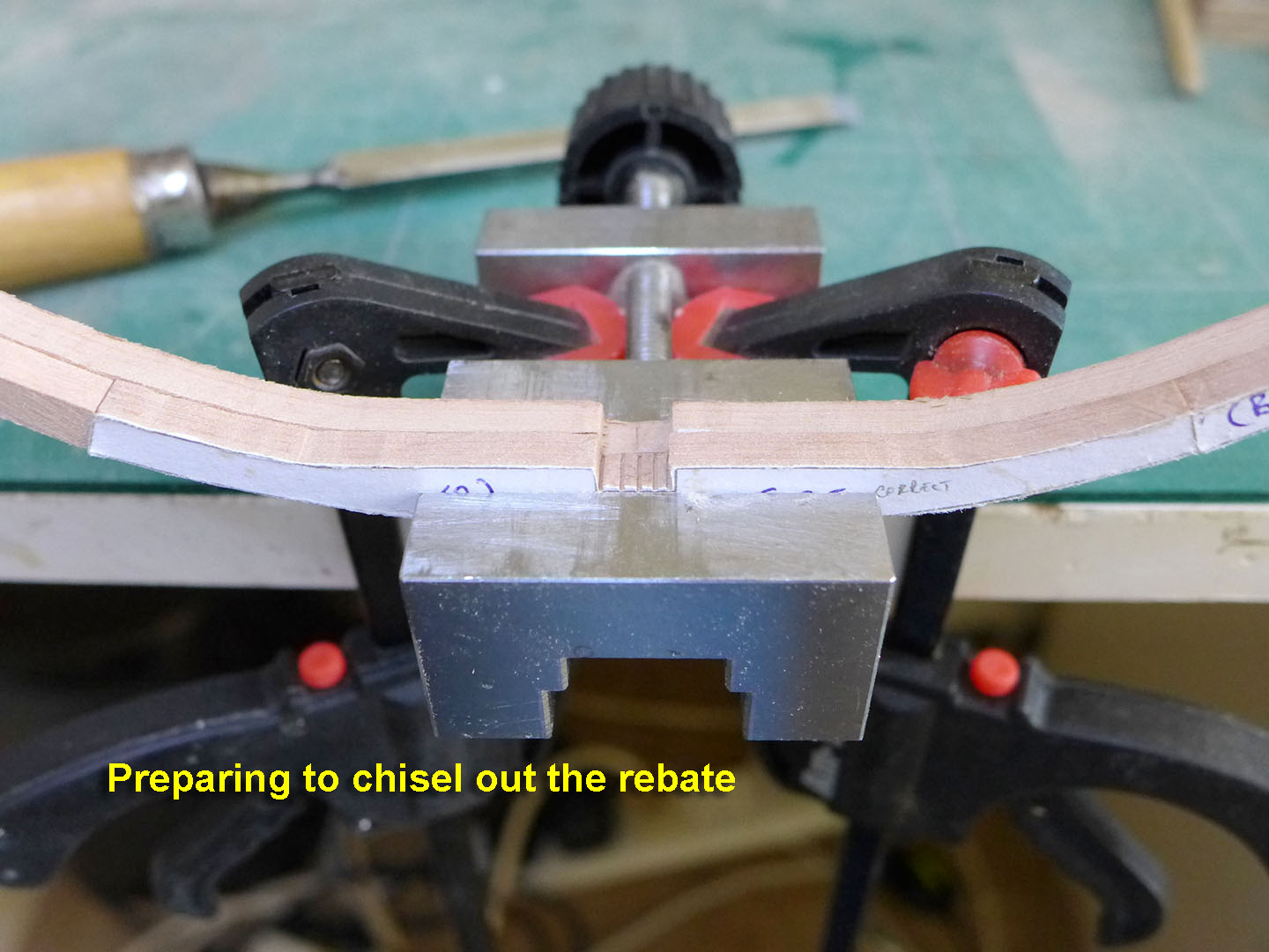
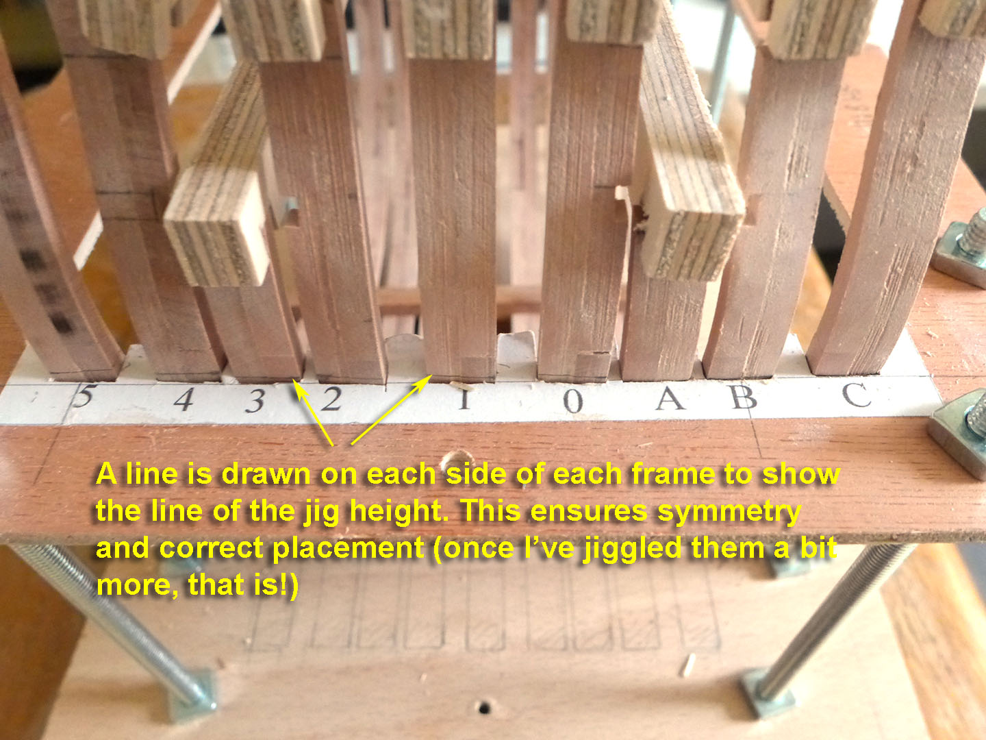
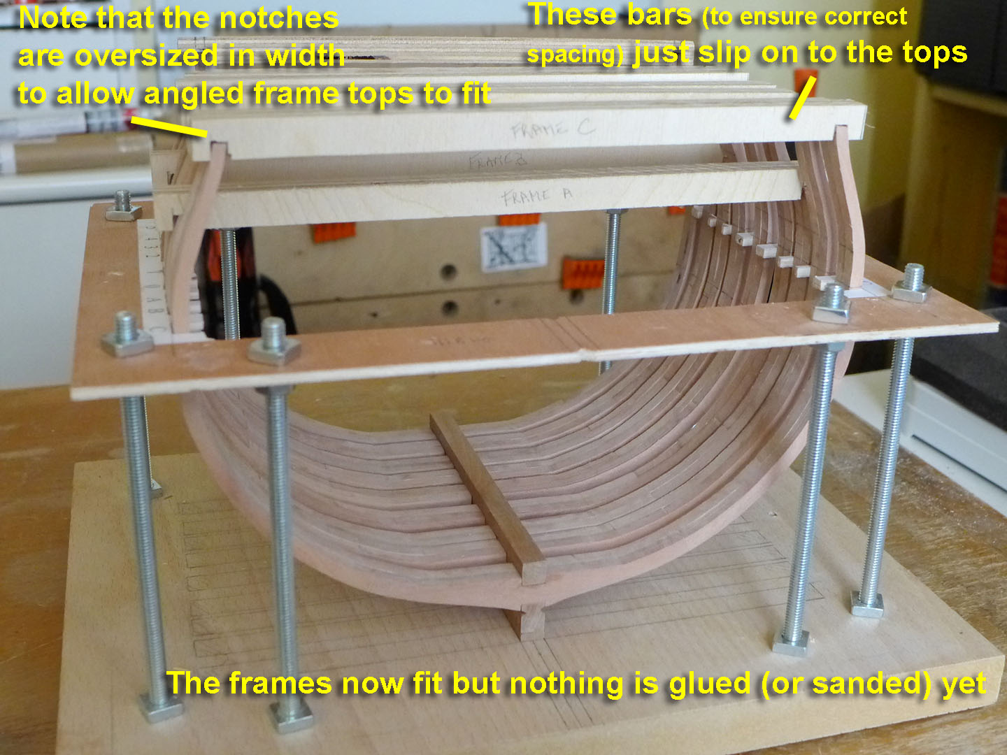
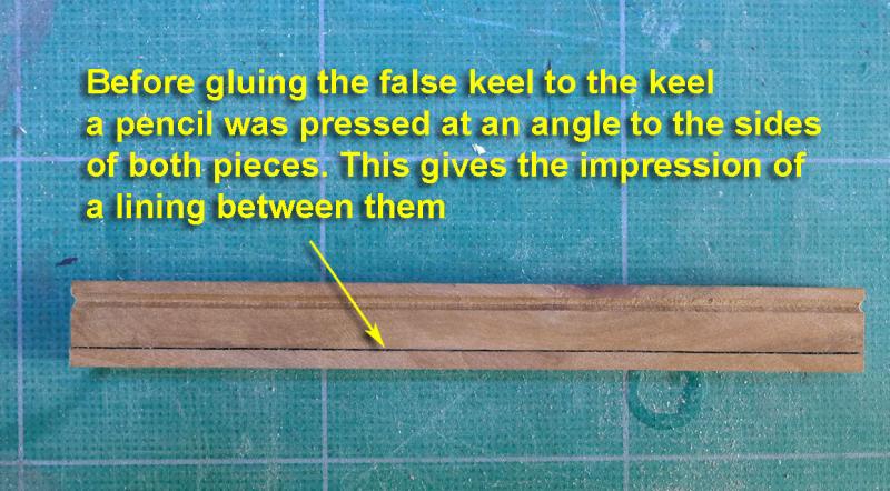
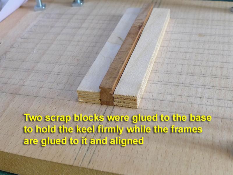
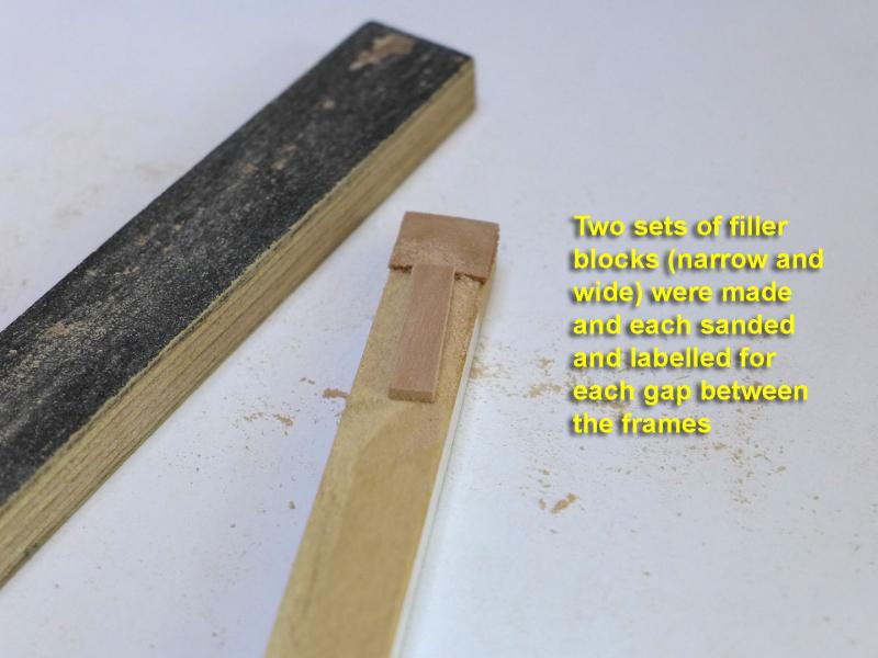
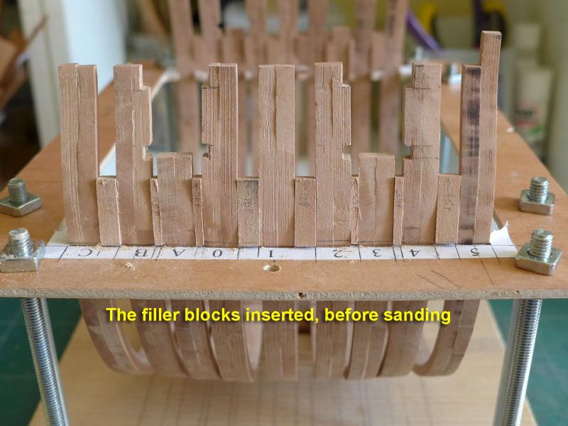
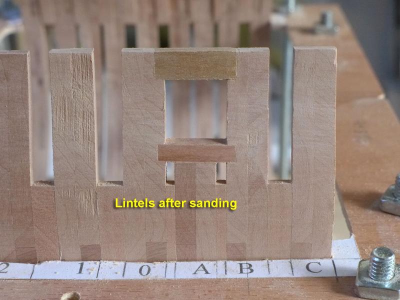
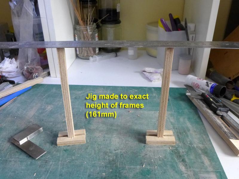
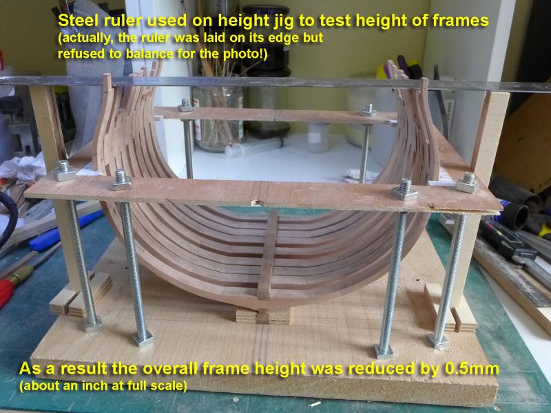
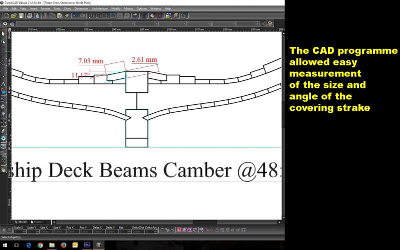
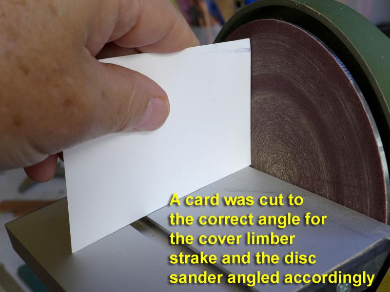
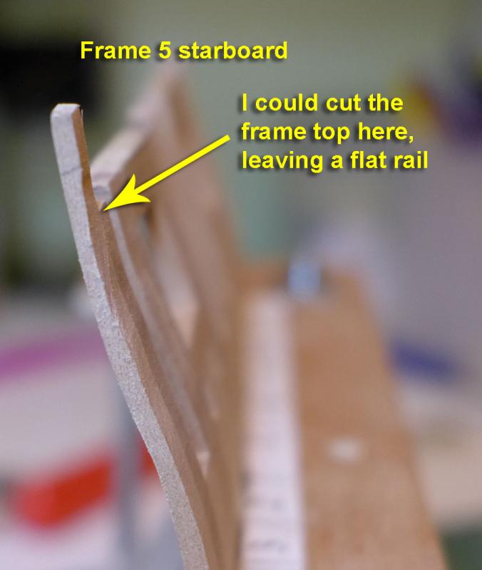
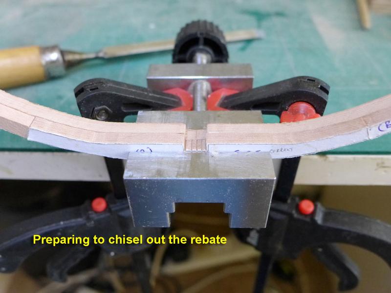
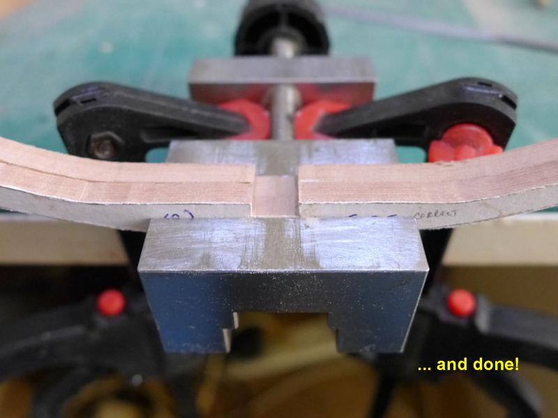
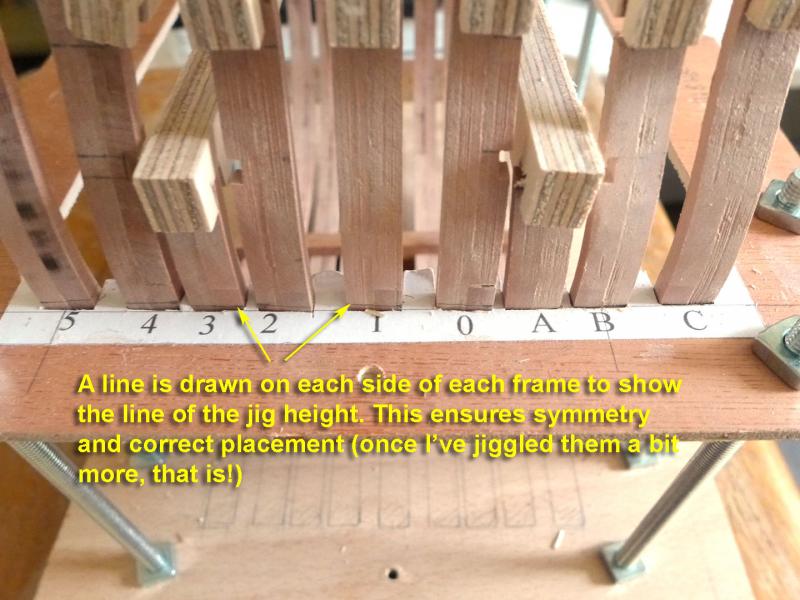
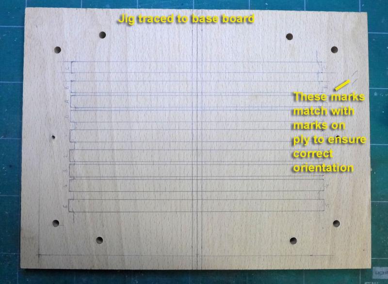
Now that the frames were seen to align, I started the process of putting them all together. First was to glue the false keel to the keel. Rather than try putting a strip of cartridge paper between the keel and false keel, I used the old trick of running a pencil at an angle to the the joining edges of both parts. That gave the satisfactory impression of a filler. I then made sure the keel would stay in place by gluing two ply offcuts on the base board to either side. I could then fix the frames to the keel with epoxy adhesive and clamp them firmly using an old oak floor tile. FILLER/SPACER BLOCKS Then came the filling blocks to keep the frame spacing constant and to add rigidity. I made two sets – a set for the narrow spaces, and another for the wider ones – then sanded each one carefully to the exact width of each space, labelling them in the process. LINTELS I added the gunport lintels as follows: A HEIGHT JIG I tested the overall heights of the frames by making an extremely simple jig cut to the correct heights. A steel ruler (on its edge) was then placed across the frames on the height jig to test the frame heights. Needless to say there was some variation -- about half were the correct height and half were 0.5mm too low. I had a choice of either sanding down and then adding a strip of wood to achieve the correct height, or simply sanding down by 0.5mm to achieve the correct height throughout. I took the easy course and lopped 0.5mm from the frames that had the correct height – in the supposition that it won’t make much difference to this learning exercise. LIMBER STRAKES I cut the first limber strakes using the table saw for the indentation. I finished the edging off with a scalpel and file. The angled cover I then thought for a while about how to make the angled cover that lies between the keel and the first limber strake. I made the necessary measurements with TurboCAD. I settled on trying to angle the cover with the disc sander, as by chance the length of the strakes is almost exactly the width of the sander. I cut a carboard template to the correct angle and used that to set the angle on the disc sander. Then, extremely gently, I angled each side of the cover strake. DECISION TIME Before I get on with laying the limber strakes and continuing with the build, I have a serious decision to take. I’m still thinking about this, but while I was sanding the frames down I found that not only were the frames quite uneven (so that it would take a lot of sanding to achieve a really smooth and even surface from fore to aft) but that in my vain attempt at narrowing the frames towards the top I had not noticed that I had sanded the top half of a lot of frame 5 far too much on each side, and some of frame C on the port side. I was on the point of abandoning the work so far and shared my thoughts with my wife. I think she was horrified at having to endure the noise of all that sawing, scroll sawing and sanding again, and she suggested I should continue even if it meant some imperfection – especially as I was supposed to be doing this as a simple learning exercise. I’m still not really decided about this. Argument for starting again: Polish the skill by making the frames again. Arguments for just continuing with the existing frames: (1) it means ordering more wood. (2) it might end up with another set of mistakes. (3) in reality a little bit of unevenness will be masked considerably by the planking. (4) I could lop off the tops of the end of frame 5 and after planking fill in any gaps with filler. (5) I have in reality learned a lot about making frames in the process, and am likely to be more careful when it comes to my next build. (6) The greater part of the build is yet to come, with more skills to be learnt about placing beams and other structures, let alone planking and finishing. On the whole I’m leaning towards just continuing, and cutting off the tops of the rear parts of the 4th futtocks of frame 5 -- leaving a flat rail without the higher curled rail. I have noticed that some builds have done this anyway. By the time of my next log (and leaving time for comments on how to proceed from any interested parties) I’ll be sure to let you know. Tony


- 132 replies
-
- 10
-
-
- triton cross-section
- cross-section
- (and 1 more)
-
Thanks, Mark. Just following your footsteps! Tony
- 132 replies
-
- 2
-
-
- triton cross-section
- cross-section
- (and 1 more)
-
Thanks a lot, Carl. You're absolutely right. I enjoy each stage in its own right and am constantly fascinated by the learning and understanding each stage brings. It also continues to add greater appreciation of the difficulties others have overcome in their own builds as I go through those stages. The other saying common on this site is that we are all our own worst critics. I have that syndrome recurring frequently, so it's always nice to hear encouragement from others with lots of experience such as yourself. One of the functions and joys of the forum! Tony
- 132 replies
-
- 2
-
-
- triton cross-section
- cross-section
- (and 1 more)
-
Thanks for all the likes! Mike: Thanks also for your comments. I have admired the way you have approached the Oliver Cromwell with such very careful preparation. At the moment wish I had been a bit more painstaking in preparation of the frames. I'm waiting to see whether I need to re-do some of them once I have done a bit more work on them. The trouble is I've been treating this cross-section merely as a learning exercise, and it would probably be better that I treat it with the care and attention due to a model that I would look at with pleasure! I surprised myself with the Sherbourne, which I also treated as a learning exercise, but once I'd finished it I found myself looking at it today with a certain amount of satisfaction -- even knowing all the faults! Despite this worry, even if I continue it as a learning exercise this build is wonderful, and I'm enormously grateful to all those who've put the time and effort into designing it as such. It really does prepare me for a future build, and I love the new intricacy and precision demanded in the frame-making process. Tony
- 132 replies
-
- 6
-
-
- triton cross-section
- cross-section
- (and 1 more)
-
That's nice of you, fellow Czech! (I was born in Prague, but now live in the UK). I've enjoyed your log too -- except you're doing better than I am in paying attention to the treenails! I'm still debating whether I will add any treenails, but I can see it's good practice. Tony (who unfortunately speaks no Czech at all as my father refused to let me speak it. We were political refugees and he thought we'd never be able to return).
- 132 replies
-
- 4
-
-
- triton cross-section
- cross-section
- (and 1 more)
-
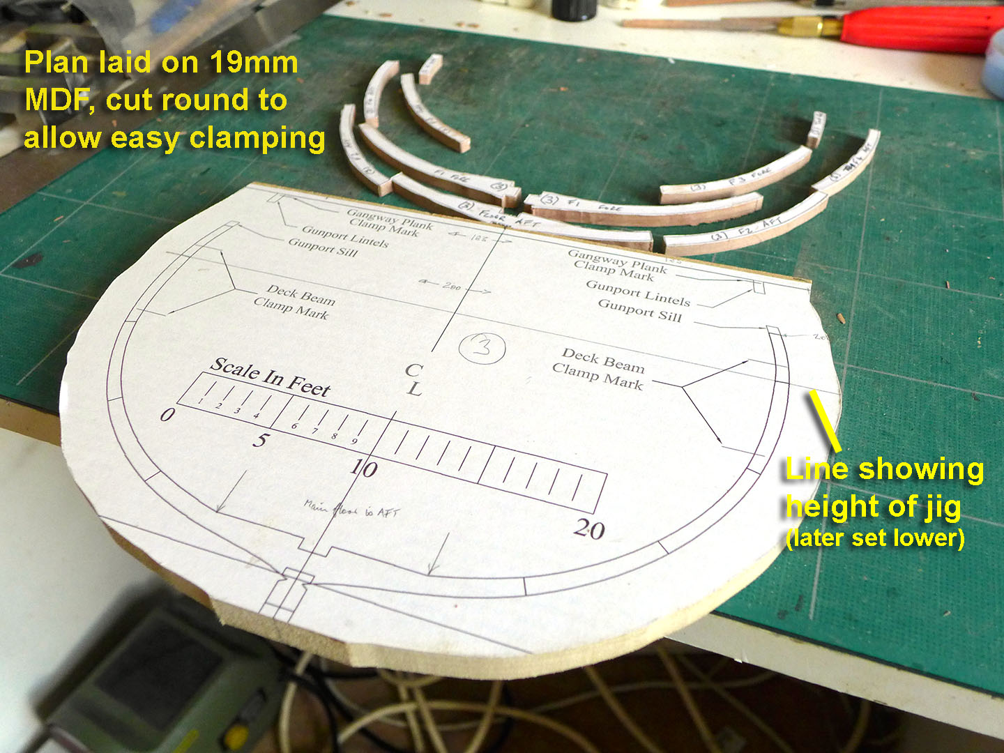
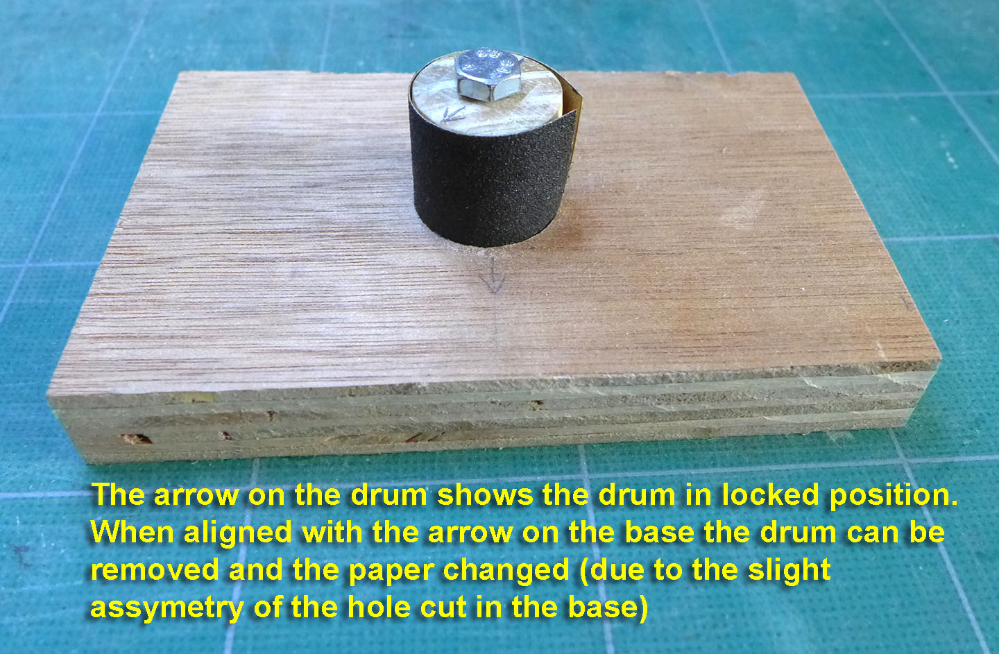
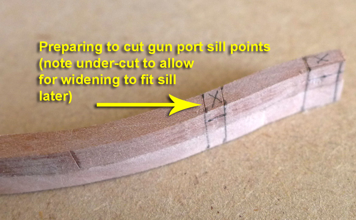
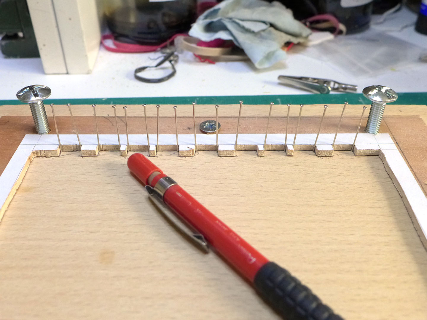
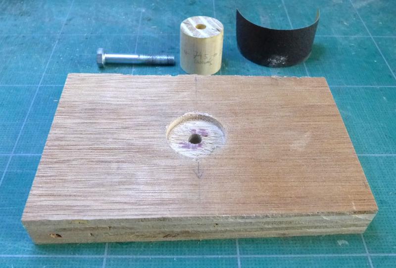
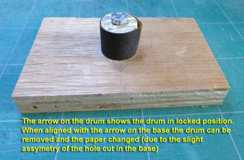
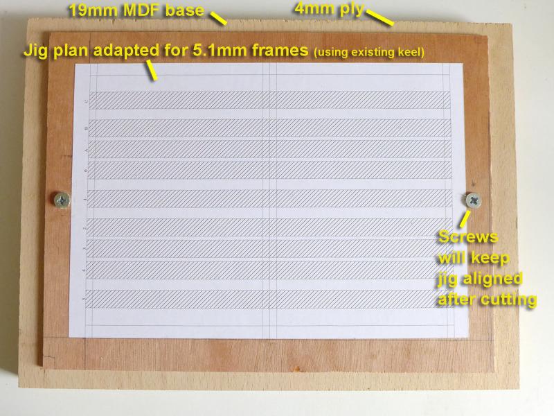
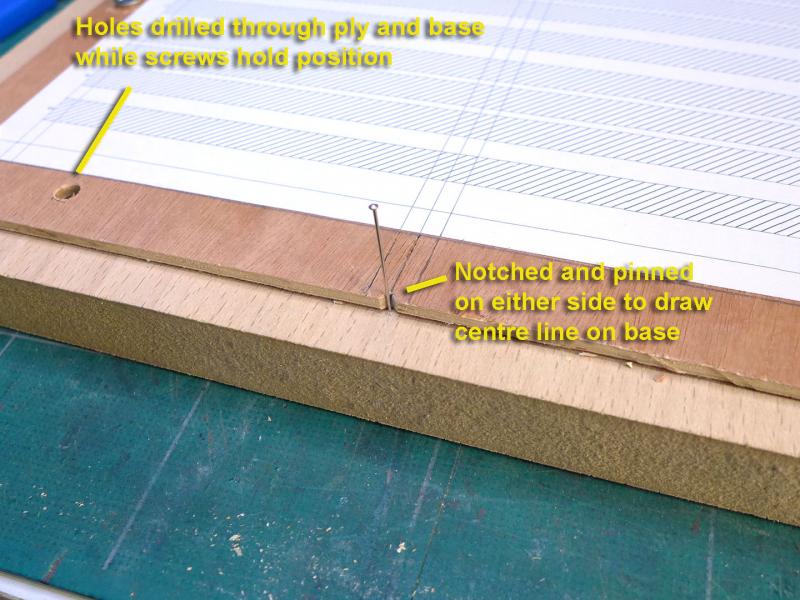
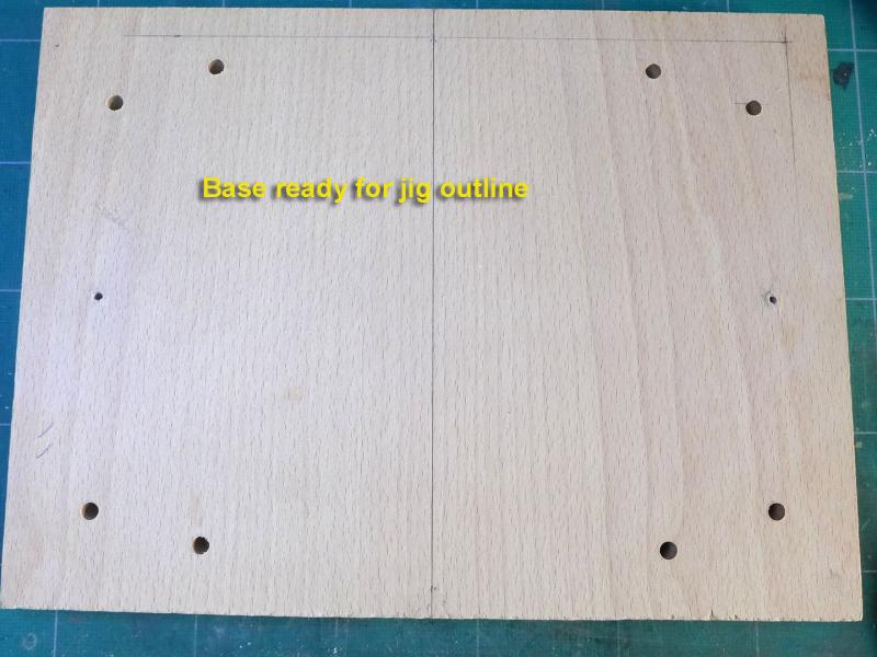
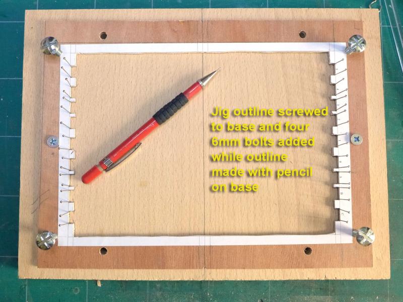
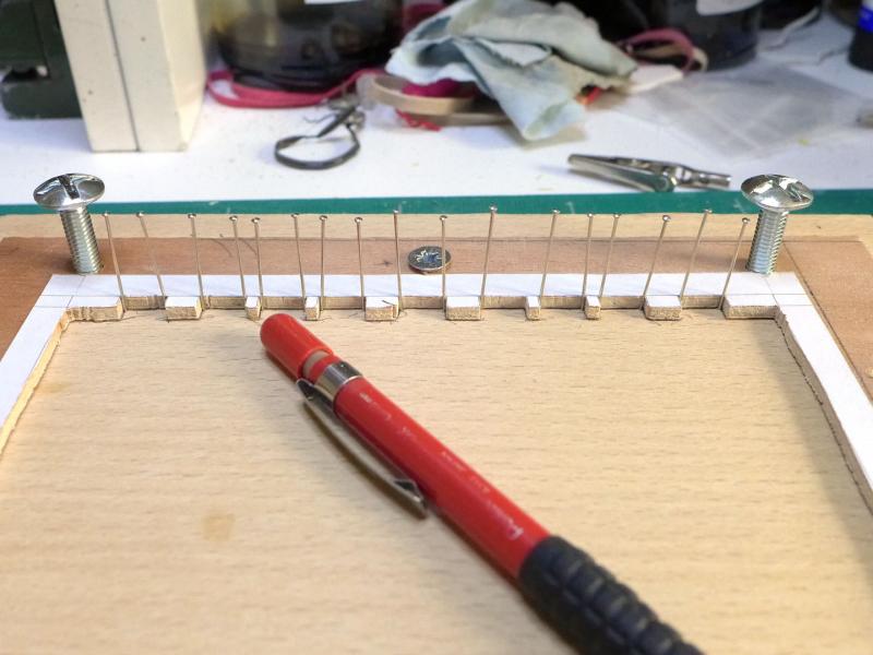
Once the wood arrived, I could set about making the frames. I laid the plan on 19mm MDF and proceeded as follows I decided I'd also cut the gun port sill placements at this stage, and hope to make sure they're all aligned later. The following shows my rough alignment of the frames in the jig. By the way, I used lock nuts to support the ply cut-out. This made sure that there would be no slipping of the cut-out and maintained the height accurately. So now I can see that at least the frames fit and are roughly aligned. Phew! That means I can now get on with truing up the frames, gluing the keel bits together and the frames to the keel, and making sure the gun port sills are ready. A SILENT DRUM SANDER! As a slight aside, my mini-drill made such a noise with sanding the frames that I had to develop a silent sanding drum for night-time work as follows. I used an old broom handle (just under an inch diameter) for the drum, and a one inch spade bit together with a 6mm roofing bolt. Peace at last! (but sore fingers, too!) Tony


- 132 replies
-
- 12
-
-
- triton cross-section
- cross-section
- (and 1 more)
-
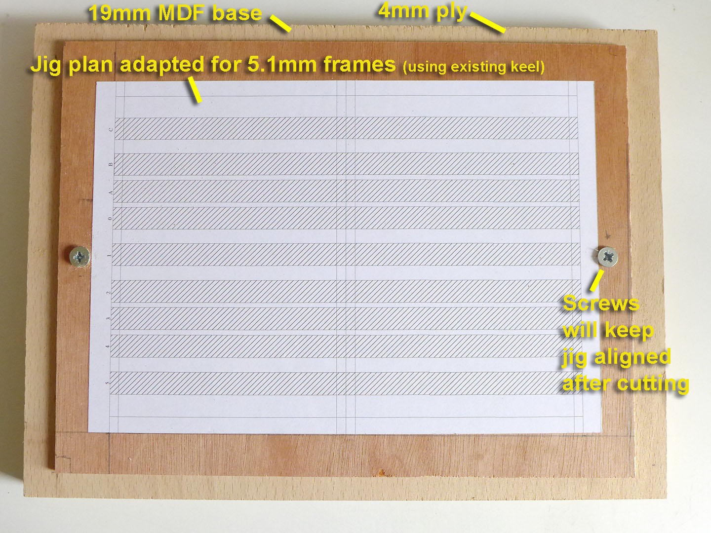
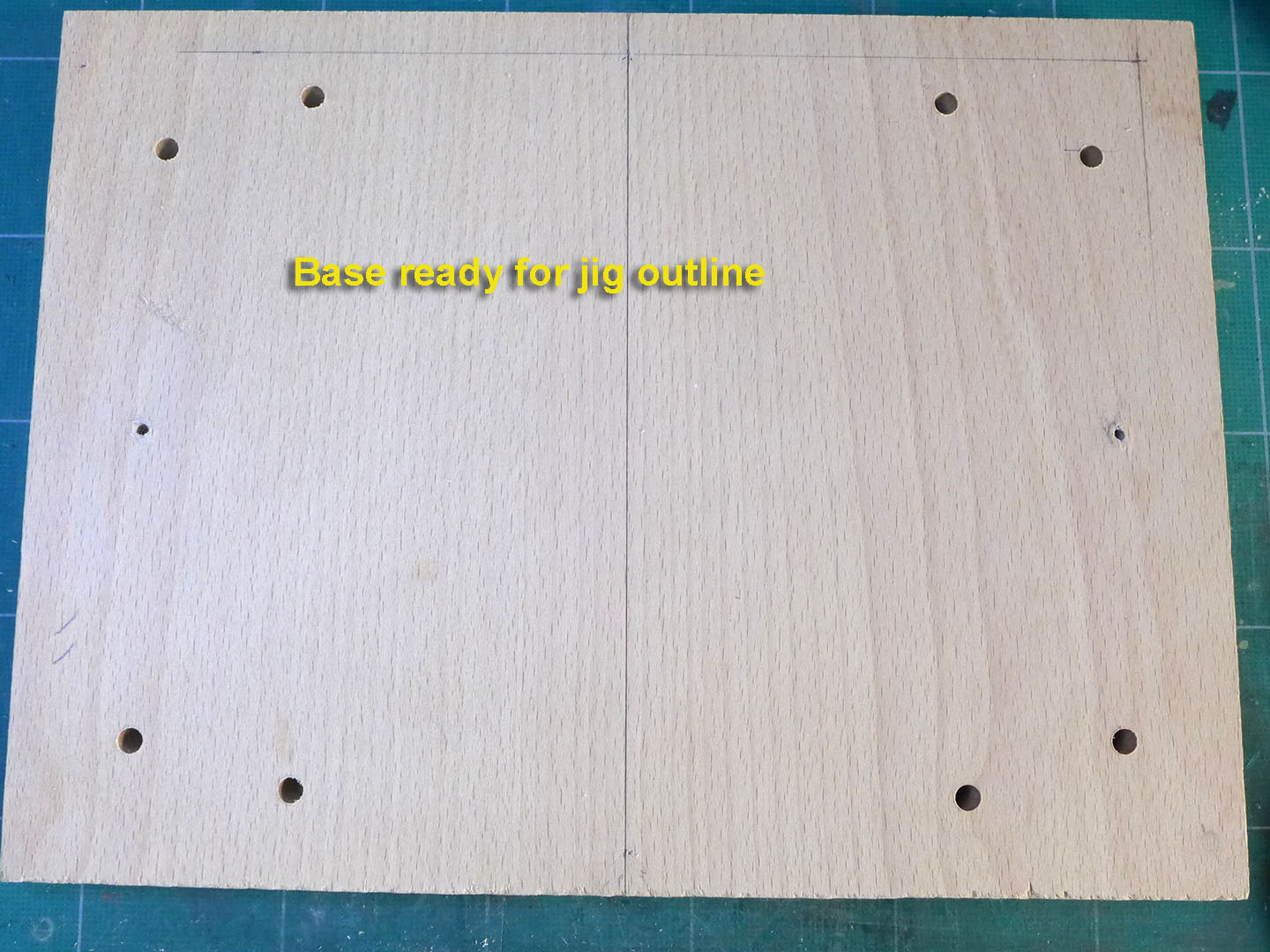
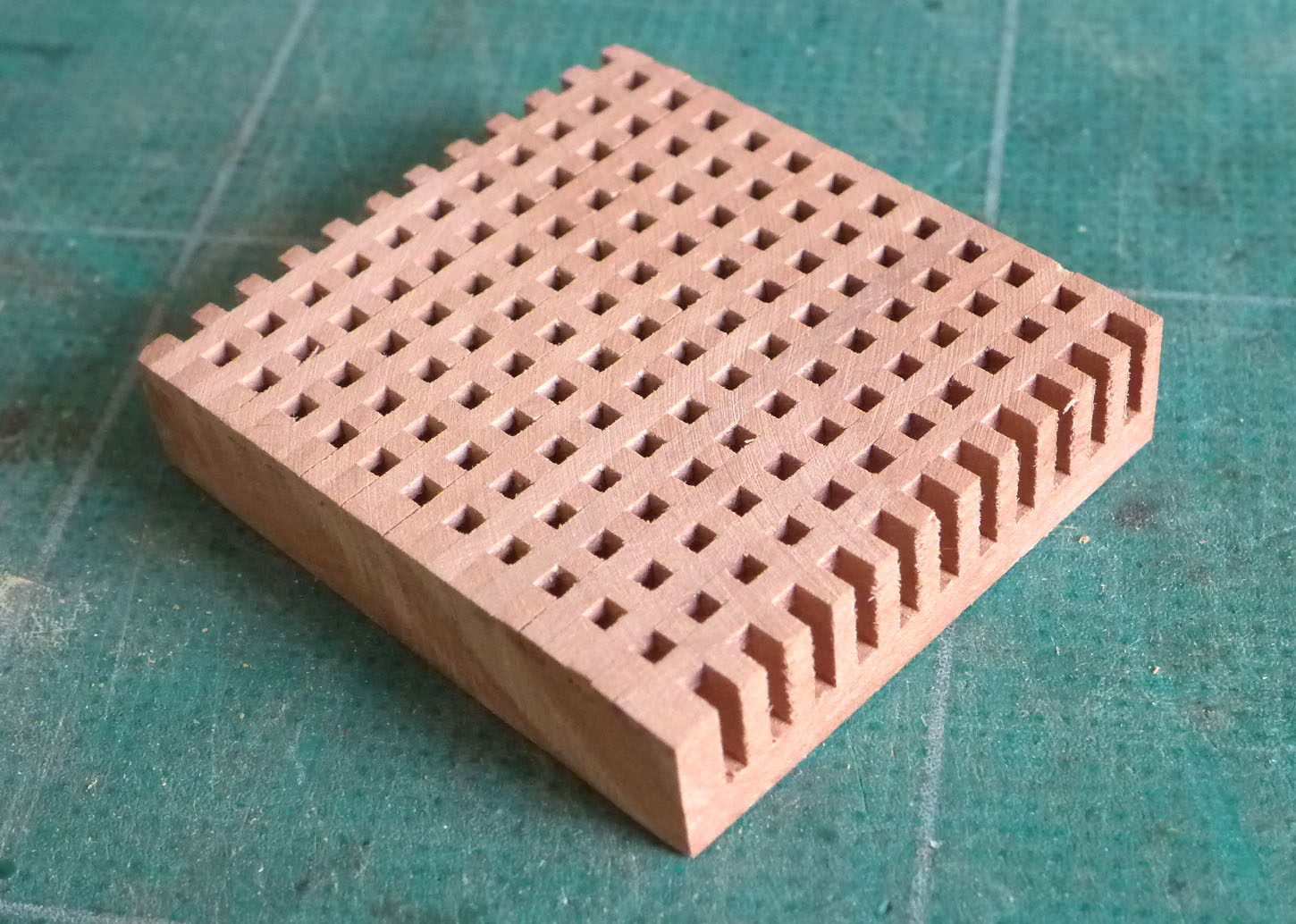
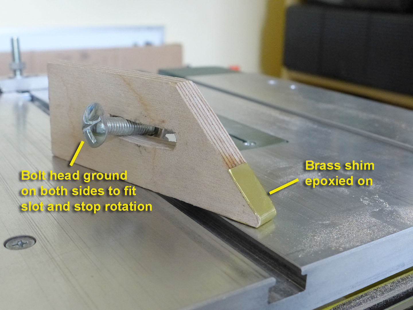
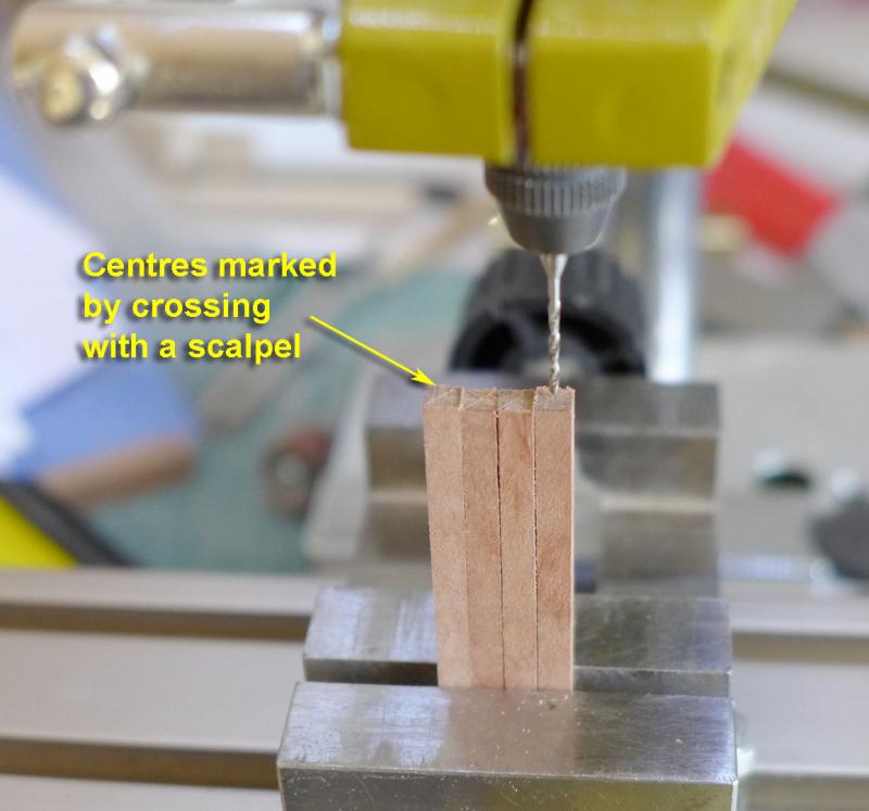
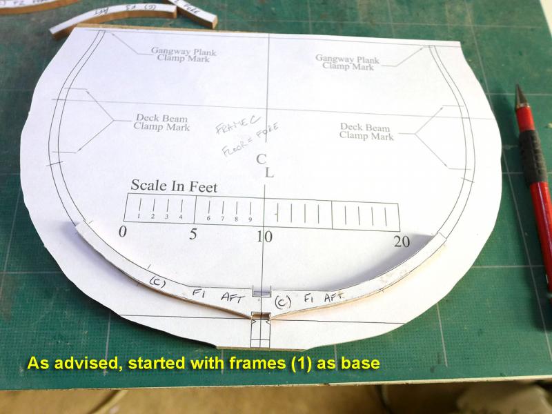
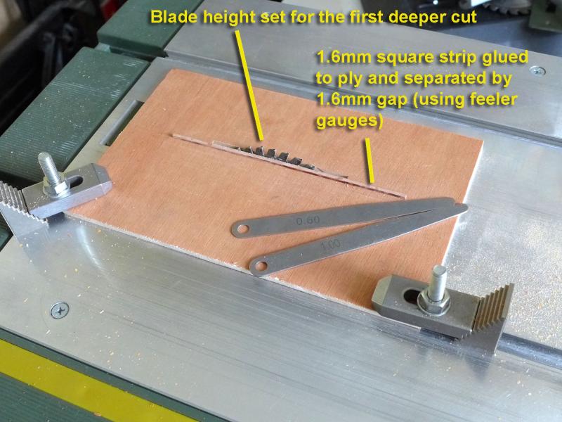
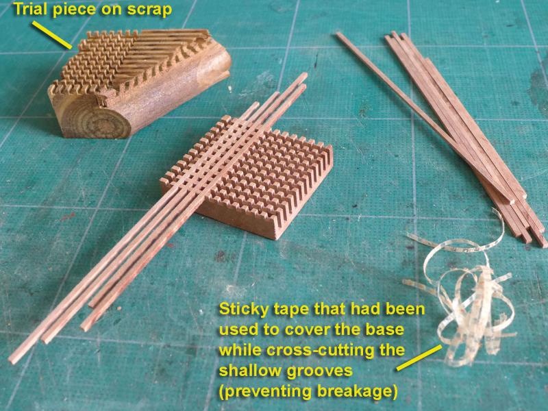
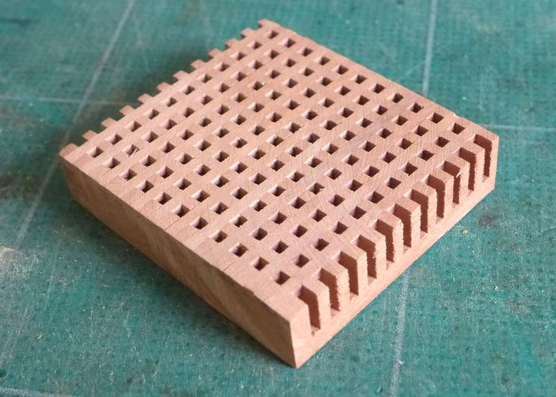
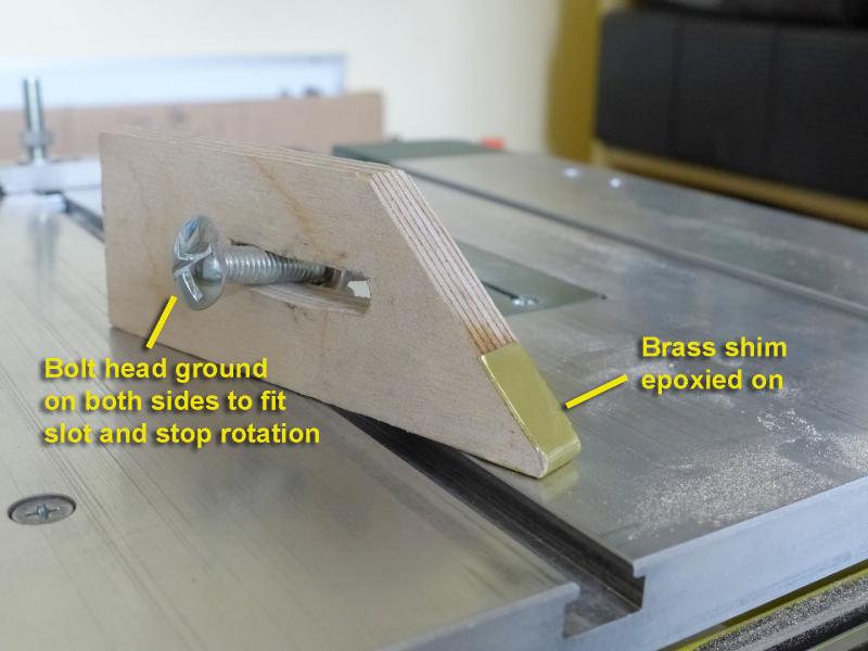
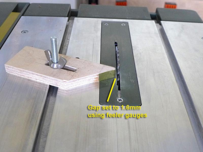
The story so far: Studied the plans, lots of the cross-section build logs, David Antscherl’s Fully Framed model books. Ordered most of the wood from Arkowood, using the suggested timber list on the forum as well as some chunks of pear I already had. Most of the model will be in pear, but I’ll use maple for the deck planking, and I’ll stain or paint the pear for the wales. I copied the plans in TurboCAD. This was quite important because the wood thickness for the frames turned out to be 5.1mm, and as I don’t have a thicknesser it was useful to ensure correct spacing of the frames along the keel. It was also useful to have the CAD programme to develop a jig. I had a little debate with myself about a scroll saw. Up to now I’ve been happy using a coping saw and a jeweller’s saw for various intricate cuts. However, I also found that for thick pieces it was tiring when there were several to do. Luckily an excellent reconditioned Proxxon DSH came up from Axminster on eBay and I was lucky to get it at a knock-down price. Decision made! I quickly modified it by making a zero-clearance top from a sheet of Perspex I found in the road outside my house. The first practical step, then, was to make the jig. I went with the type that puts the spacing in between the frames. The base was made of 19mm MDF, the top from 4mm ply (again found in the streets around my house). You can see the steps in the following photos. Having set up my jig, I was still waiting for the wood from Arkowood, so I thought I’d make the grating. I used the traditional method shown by Frolich in his book ‘Art of Ship Modelling’. The slats were made after I had made a very simple stop from a piece of plywood, a 6mm bolt with its head filed down to fit the slot (and thereby stopping it rotating) and a strip of brass shim shaped round the edge of the ply to stop wear on the point. Next up: making the frames Tony
- 132 replies
-
- 8
-
-
- triton cross-section
- cross-section
- (and 1 more)
-
I enjoyed the sub-title translation at the end of their video. "I'll bananas conecto pieces..." instead of 'Albion Connecto pieces'. Tony
-
Glad you're posting the log. I look forward to following the rest of the build. Tony
- 25 replies
-
- 2
-
-
- finished
- sherbourne
- (and 1 more)
-
Looking forward to the build! Tony
-
Olson recommends grinding off the back corners of their blades for a smoother cut and tighter curves. They sell a 'blade finishing stone' together with instructions. I just downloaded the instructions. The way to do it is by grinding when the blade is moving. For very thin blades they recommend doing it while the blade is cutting wood. Tony
-
Delighted you're in on this, Mike. I've come as far as making the first frame and the jig, but not yet posted progress as I decided I'd use the first frame as a learning exercise and might well make the same frame again as I have some burn marks on it after drum sanding. I also bought M6 bolts that were 10mm too short for the jig as I hadn't taken into account the width of the base plate! So I look forward to your build with great pleasure as I'm sure you'll have plenty of good ideas. Tony
-
I have the Proxxon FET saw and have no problem milling wood to 0.1mm consistency for the thicknesses I use. If there's a trick it's getting to know the right sequence in tightening the fence, using a variable stop (there are several types shown on this site), and a featherboard -- as well, of course, as a zero insert which is easy to make for each blade that you use. You also have to ensure the saw blade and fence are correctly angled, though you'd be doing that during set up. Most European modellers seem to use this saw with superb results, although there are also a few specialist saw makers around as well. Frolich used a saw attachment on his old Unimat lathe with wonderful results. I understand the Byrnes saw may obtain great results more easily, but as usual it's a question of how much you want to pay for ease of use. Tony
-
Thanks for such a nice note, Gregor. It was really great how you, Dirk and Kester shepherded and guided me through the various stages. I learnt a lot also from the various discussions you had between yourselves about the finer points of historical interest. I had no idea at all that I had been a motivator for you to build the Sherbourne! Tony
- 269 replies
-
- 1
-
-
- Caldercraft
- First build
- (and 3 more)